sls manual
TRANSCRIPT
COMMUNITY SOLUTIONS™
Owner’s Manual
SLS Full-Range Loudspeakers And
SBS Subwoofers

PAGE 2 Community Solutions™ Owner’s Manual
A TRADITION OF EXCELLENCE AND INNOVATION
Since the founding of our company in 1968, Community has been a constant developer and innovator of loudspeaker technology. Many of our engineering achievements were undertaken to solve problems, when no prior solutions existed. Others resulted from simply seeing a better way to do things. Over the years our technologies have been imitated, and our methods have become common practice throughout the professional sound industry. However, developments like carbon fiber diaphragm compression drivers still stand alone, and well ahead of the competition. Just a few of Community’s unique accomplishments include the following: • First successful fiberglass mid, high frequency, and large-format bass horns.
• First compression loaded mid-range horn for touring systems - the LMF.
• First suspension-less diaphragm HF driver - the VHF100.
• First mid-range, full-decade (200 Hz - 2 kHz) high-power compression driver - the M4.
• First carbon fiber diaphragm compression drivers - M4, EM280, EM282.
• First Ferrofluid-cooled professional woofers - the VBS Series.
• First product series with all drivers Ferrofluid-cooled.
• First air-cooled loudspeakers for touring systems - AirForce.
• First three-way cinema loudspeaker systems - Paramount Executive Studio Theatre, Warner Bros. screening theatre and dubbing rooms.
• First electro-acoustic system to equal the sound level of pneumatic warning sirens.
• First to provide loudspeaker coverage over an entire country - Denmark Emergency System.
• First comprehensive, calibrated data acquisition of sound reinforcement products.
• First integral signal-aligned three-way sound reinforcement systems - RS Series.
• First pro audio company with an Internet Web site.
• First all horn-loaded, high-fidelity, weather-resistant loudspeaker - R2 Series. In line with our history of excellence and innovation, each Community product is manufactured in accordance with a complicated and exacting chain of procedures that ensure absolute quality. With our unique designs, our sophisticated techniques, and our proprietary materials and transducers, we are committed to bringing only the finest audio products to the many thousands of professional sound engineers, performers, and end users who rely on them daily.
Community Professional Loudspeakers 333 East Fifth Street
Chester, PA 19013-4511 USA TEL: 1-(610) 876-3400 FAX: 1-(610) 874-0190
© 2010 All Rights Reserved

PAGE 3 Community Solutions™ Owner’s Manual
EC STATEMENT OF CONFORMITY This document confirms that the range of products of Community Professional Loudspeakers bearing the CE label meets all of the requirements in the EMC directive 89/336/EEC laid down by the Member States Council for adjustment of legal requirements. Furthermore, the products comply with the rules and regulations referring to the electromagnetic compatibility of devices from 30-August-1995. The Community Professional Loudspeaker products bearing the CE label comply with the following harmonized or national standards: DIN EN 55013:08-1991 DIN EN 55020:05-1995 DIN EN 55082-1:03-1993 The authorized declaration and compatibility certification resides with the manufacturer and can be viewed upon request. The responsible manufacturer is the company: Community Light & Sound 333 East Fifth Street Chester, PA 19013 USA TEL: 1-610 876-3400 FAX: 1-610 874-0190 Chester, PA USA July 2010
PAGE 4 Community Solutions™ Owner’s Manual
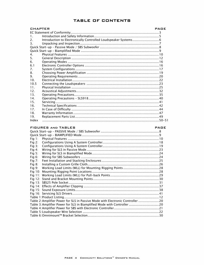
TABLE OF CONTENTS
CHAPTER PAGE EC Statement of Conformity .............................................................................................. 3 1. Introduction and Safety Information ..................................................................... 5 2. Introduction to Electronically Controlled Loudspeaker Systems ............................ 6 3. Unpacking and Inspection .................................................................................... 7 Quick Start-up – Passive Mode / SBS Subwoofer ............................................................... 8 Quick Start-up – Biamplified Mode ................................................................................... 9 4. Physical Features ................................................................................................. 10 5. General Description ............................................................................................. 12 6. Operating Modes ................................................................................................. 16 6.1 Electronic Controller Options ............................................................................... 16 7. System Configurations ......................................................................................... 17 8. Choosing Power Amplification ............................................................................. 19 9. Operating Requirements ...................................................................................... 20 10. Electrical Installation ............................................................................................ 22 10.5 Connecting the Loudspeakers ............................................................................. 23 11. Physical Installation ............................................................................................. 25 12. Acoustical Adjustments........................................................................................ 32 13. Operating Precautions.......................................................................................... 35 14. Operating Precautions – SLS918 ........................................................................... 40 15. Servicing .............................................................................................................. 41 16. Technical Specifications ....................................................................................... 42 17. In Case of Difficulty ............................................................................................. 44 18. Warranty Information ........................................................................................... 47 19. Replacement Parts List ......................................................................................... 49 Index ............................................................................................................................ 50-51 FIGURES and TABLES PAGE Quick Start-up – PASSIVE Mode / SBS Subwoofer .............................................................. 8 Quick Start-up – BIAMPLIFIED Mode .................................................................................. 9 Fig 1: Physical Features ................................................................................................. 10 Fig 2: Configurations Using A System Controller............................................................ 18 Fig 3: Configurations Using A System Controller............................................................ 19 Fig 4: Wiring for SLS in Passive Mode ............................................................................. 23 Fig 5: Wiring for SLS in Biamplified Mode ....................................................................... 24 Fig 6: Wiring for SBS Subwoofers ................................................................................... 24 Fig 7: Feet Installation and Stacking Enclosures ............................................................. 25 Fig 8: Installing a Custom Grille Cloth ............................................................................ 26 Fig 9: Working Load Limits (WLL) for Mounting/Rigging Points ...................................... 28 Fig 10: Mounting/Rigging Point Locations ....................................................................... 28 Fig 11: Working Load Limits (WLL) for Pull-back Points .................................................... 29 Fig 12: Stand and Bracket Mounting Points ...................................................................... 30 Fig 13: SBS25 Pole Socket ................................................................................................ 31 Fig 14: Effects of Amplifier Clipping ................................................................................ 37 Fig 15: Sound Exposure Limits ......................................................................................... 38 Fig 16: Servicing SLS Drivers ............................................................................................ 41 Table 1: Product Listing ..................................................................................................... 12 Table 2: Amplifier Power for SLS in Passive Mode with Electronic Controller ...................... 20 Table 3: Amplifier Power for SLS in Biamplified Mode with Controller ................................ 20 Table 4: Amplifier Power for SBS with Electronic Controller ................................................ 21 Table 5: Loudspeaker Wire Selection ................................................................................. 22 Table 6: Omnimount™ Bracket Selection ............................................................................ 30
PAGE 5 Community Solutions™ Owner’s Manual
COMMUNITY SOLUTIONS™ OWNER’S MANUAL 1 INTRODUCTION
Welcome! You’ve joined the group of people that have chosen high quality Community loudspeaker systems and components for 30 years. We’re really gratified you did and we will do our best to make sure you are satisfied with your new loudspeaker. In order for you to get the most effective use of this product please take a few minutes to read this manual. We have included a great deal of useful information that will help you to realize the best performance, operation, sound quality, and reliability from your new loudspeaker. 1.1 Community Solutions Loudspeaker Systems This manual contains information for the proper set-up and operation of the Community Solutions Series loudspeaker systems consisting of the SLS full-range loudspeakers and SBS subwoofers. While every attempt has been made to ensure this information is correct and up to date, Community continuously incorporates worthwhile improvements to each product which may include changes and/or modifications not contained in this manual. 1.2 IMPORTANT SAFETY INFORMATION The terms “Caution,” “Warning,” and “Danger” are used throughout this manual to alert the reader to important safety considerations. If you have any questions about any aspects of these cautions, contact your local dealer, distributor or Community.
CAUTION: describes an operating condition or user action that may expose the equipment or user to potential damage or danger. WARNING: describes an operating condition or user action that will cause damage to the equipment or injure the user. DANGER: describes an operating condition or user action that will immediately damage the equipment or be extremely dangerous or possibly life-threatening to the user.
PAGE 6 Community Solutions™ Owner’s Manual
2 INTRODUCTION TO ELECTRONICALLY-CONTROLLED
LOUDSPEAKER SYSTEMS
In simple terms, an electronically-controlled loudspeaker system consists of: 1. The loudspeaker components and enclosure. 2. An associated electronic device that modifies the source signal in some fashion. 3. The power amplifier used to drive the loudspeaker system.
A properly designed electronically-controlled loudspeaker system, in combination with a power amplifier of appropriate rating, will provide enhanced performance over a non-electronically-controlled loudspeaker in one or more of the following ways:
• Improved frequency response • Maximized power handling • Higher acoustic output • Lowered distortion • Protection of the loudspeaker system components
All loudspeaker systems have frequency response limitations. Flat response from a system is typically attained by lowering the output in certain portions of the system’s passband to match the lower output of the system at other frequencies within its passband. As a consequence the overall sensitivity of the system is lowered. Rather than modifying the system, the input signal may be modified by an electronic controller to compensate for those areas within the system’s passband where it would normally have lower output. In this way flat frequency response can be achieved while maintaining the sensitivity of the system. All loudspeaker systems have power handling limitations beyond which they can be damaged. An electronic model may be developed with characteristics that help prevent exceeding the mechanical and/or thermal limits of the system’s components. For example, suppose it can be determined with accuracy that an input signal of 20 volts to the voice coil of a driver will cause the voice coil former to strike the rear of the magnet assembly. If the electronic model for this speaker is designed so that the input signal to the driver’s voice coil may never exceed 19.5 volts, then it should never be capable of bottoming out. Some other important operational characteristics may also be addressed by a controller. One is compensating for the natural characteristics of human hearing, which does not “hear” low frequencies and high frequencies as well at lower sound pressure levels. The controller can increase the output of these frequencies at low volume (in essence, a sophisticated loudness control). The controller can then reduce the output at these frequencies as the signal level is increased. Another is providing an electronic crossover function; while yet another might be to correct for phase anomalies in the loudspeaker system. A properly designed electronic system controller will provide the necessary equalization, compression, and limiting required for the associated loudspeaker system. It will do this inaudibly when the loudspeaker system is operated within its rated power constraints. Even when this boundary is exceeded, it will apply control in a manner that is audibly acceptable.
PAGE 7 Community Solutions™ Owner’s Manual
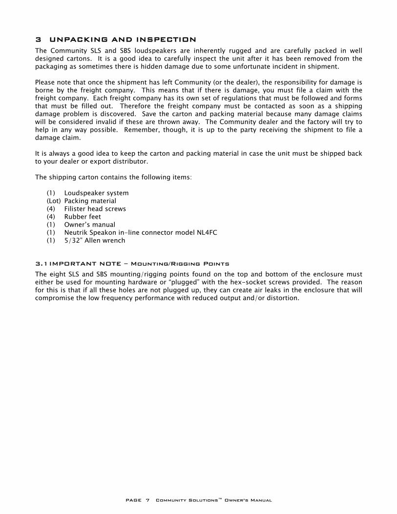
3 UNPACKING AND INSPECTION The Community SLS and SBS loudspeakers are inherently rugged and are carefully packed in well designed cartons. It is a good idea to carefully inspect the unit after it has been removed from the packaging as sometimes there is hidden damage due to some unfortunate incident in shipment. Please note that once the shipment has left Community (or the dealer), the responsibility for damage is borne by the freight company. This means that if there is damage, you must file a claim with the freight company. Each freight company has its own set of regulations that must be followed and forms that must be filled out. Therefore the freight company must be contacted as soon as a shipping damage problem is discovered. Save the carton and packing material because many damage claims will be considered invalid if these are thrown away. The Community dealer and the factory will try to help in any way possible. Remember, though, it is up to the party receiving the shipment to file a damage claim. It is always a good idea to keep the carton and packing material in case the unit must be shipped back to your dealer or export distributor. The shipping carton contains the following items: (1) Loudspeaker system (Lot) Packing material (4) Filister head screws (4) Rubber feet (1) Owner’s manual (1) Neutrik Speakon in-line connector model NL4FC (1) 5/32” Allen wrench 3.1 IMPORTANT NOTE – Mounting/Rigging Points The eight SLS and SBS mounting/rigging points found on the top and bottom of the enclosure must either be used for mounting hardware or “plugged” with the hex-socket screws provided. The reason for this is that if all these holes are not plugged up, they can create air leaks in the enclosure that will compromise the low frequency performance with reduced output and/or distortion.
PAGE 8 Community Solutions™ Owner’s Manual
PAGE 9 Community Solutions™ Owner’s Manual
PAGE 10 Community Solutions™ Owner’s Manual
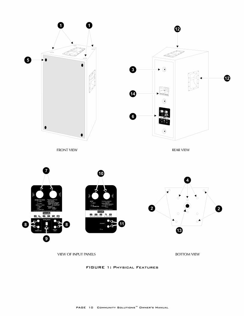
FIGURE 1: Physical Features
PAGE 11 Community Solutions™ Owner’s Manual
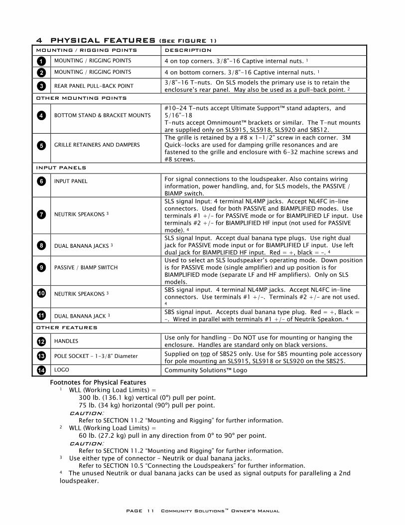
4 PHYSICAL FEATURES (See FIGURE 1)
MOUNTING / RIGGING POINTS DESCRIPTION
MOUNTING / RIGGING POINTS 4 on top corners. 3/8”-16 Captive internal nuts. 1
MOUNTING / RIGGING POINTS 4 on bottom corners. 3/8”-16 Captive internal nuts. 1
REAR PANEL PULL-BACK POINT 3/8”-16 T-nuts. On SLS models the primary use is to retain the enclosure’s rear panel. May also be used as a pull-back point. 2
OTHER MOUNTING POINTS
BOTTOM STAND & BRACKET MOUNTS
#10-24 T-nuts accept Ultimate Support™ stand adapters, and 5/16”-18 T-nuts accept Omnimount™ brackets or similar. The T-nut mounts are supplied only on SLS915, SLS918, SLS920 and SBS12.
GRILLE RETAINERS AND DAMPERS
The grille is retained by a #8 x 1-1/2” screw in each corner. 3M Quick-locks are used for damping grille resonances and are fastened to the grille and enclosure with 6-32 machine screws and #8 screws.
INPUT PANELS
INPUT PANEL For signal connections to the loudspeaker. Also contains wiring information, power handling, and, for SLS models, the PASSIVE / BIAMP switch.
NEUTRIK SPEAKONS 3
SLS signal Input: 4 terminal NL4MP jacks. Accept NL4FC in-line connectors. Used for both PASSIVE and BIAMPLIFIED modes. Use terminals #1 +/– for PASSIVE mode or for BIAMPLIFIED LF input. Use terminals #2 +/– for BIAMPLIFIED HF input (not used for PASSIVE mode). 4
DUAL BANANA JACKS 3
SLS signal Input. Accept dual banana type plugs. Use right dual jack for PASSIVE mode input or for BIAMPLIFIED LF input. Use left dual jack for BIAMPLIFIED HF input. Red = +, black = –. 4
PASSIVE / BIAMP SWITCH
Used to select an SLS loudspeaker’s operating mode. Down position is for PASSIVE mode (single amplifier) and up position is for BIAMPLIFIED mode (separate LF and HF amplifiers). Only on SLS models.
NEUTRIK SPEAKONS 3 SBS signal input. 4 terminal NL4MP jacks. Accept NL4FC in-line connectors. Use terminals #1 +/–. Terminals #2 +/– are not used. 4
DUAL BANANA JACK 3 SBS signal input. Accepts dual banana type plug. Red = +, Black = –. Wired in parallel with terminals #1 +/– of Neutrik Speakon. 4
OTHER FEATURES
HANDLES Use only for handling – Do NOT use for mounting or hanging the enclosure. Handles are standard only on black versions.
POLE SOCKET – 1-3/8” Diameter Supplied on top of SBS25 only. Use for SB5 mounting pole accessory for pole mounting an SLS915, SLS918 or SLS920 on the SBS25.
LOGO Community Solutions™ Logo
Footnotes for Physical Features 1 WLL (Working Load Limits) = 300 lb. (136.1 kg) vertical (0º) pull per point. 75 lb. (34 kg) horizontal (90º) pull per point. CAUTION: Refer to SECTION 11.2 “Mounting and Rigging” for further information. 2 WLL (Working Load Limits) = 60 lb. (27.2 kg) pull in any direction from 0º to 90º per point. CAUTION: Refer to SECTION 11.2 “Mounting and Rigging” for further information. 3 Use either type of connector – Neutrik or dual banana jacks. Refer to SECTION 10.5 “Connecting the Loudspeakers” for further information. 4 The unused Neutrik or dual banana jacks can be used as signal outputs for paralleling a 2nd loudspeaker.
PAGE 12 Community Solutions™ Owner’s Manual
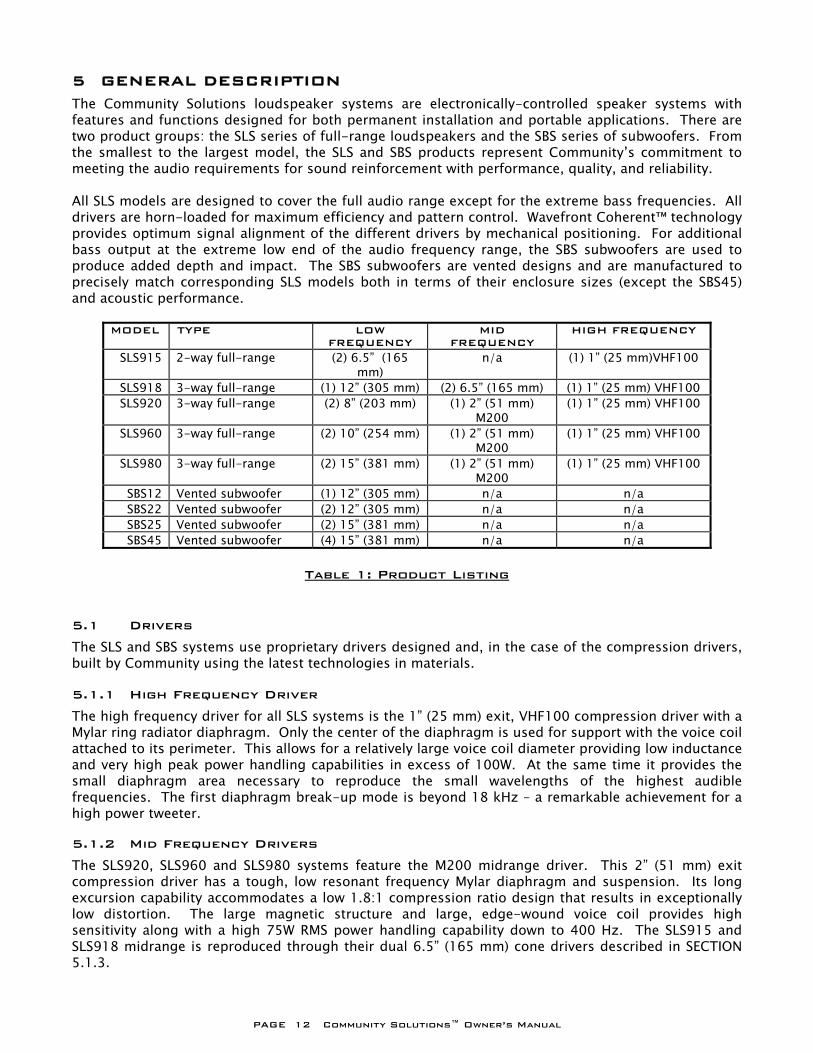
5 GENERAL DESCRIPTION The Community Solutions loudspeaker systems are electronically-controlled speaker systems with features and functions designed for both permanent installation and portable applications. There are two product groups: the SLS series of full-range loudspeakers and the SBS series of subwoofers. From the smallest to the largest model, the SLS and SBS products represent Community’s commitment to meeting the audio requirements for sound reinforcement with performance, quality, and reliability. All SLS models are designed to cover the full audio range except for the extreme bass frequencies. All drivers are horn-loaded for maximum efficiency and pattern control. Wavefront Coherent™ technology provides optimum signal alignment of the different drivers by mechanical positioning. For additional bass output at the extreme low end of the audio frequency range, the SBS subwoofers are used to produce added depth and impact. The SBS subwoofers are vented designs and are manufactured to precisely match corresponding SLS models both in terms of their enclosure sizes (except the SBS45) and acoustic performance.
MODEL TYPE LOW FREQUENCY
MID FREQUENCY
HIGH FREQUENCY
SLS915 2-way full-range (2) 6.5” (165 mm)
n/a (1) 1” (25 mm)VHF100
SLS918 3-way full-range (1) 12” (305 mm) (2) 6.5” (165 mm) (1) 1” (25 mm) VHF100 SLS920 3-way full-range (2) 8” (203 mm) (1) 2” (51 mm)
M200 (1) 1” (25 mm) VHF100
SLS960 3-way full-range (2) 10” (254 mm) (1) 2” (51 mm) M200
(1) 1” (25 mm) VHF100
SLS980 3-way full-range (2) 15” (381 mm) (1) 2” (51 mm) M200
(1) 1” (25 mm) VHF100
SBS12 Vented subwoofer (1) 12” (305 mm) n/a n/a SBS22 Vented subwoofer (2) 12” (305 mm) n/a n/a SBS25 Vented subwoofer (2) 15” (381 mm) n/a n/a SBS45 Vented subwoofer (4) 15” (381 mm) n/a n/a
Table 1: Product Listing
5.1 Drivers The SLS and SBS systems use proprietary drivers designed and, in the case of the compression drivers, built by Community using the latest technologies in materials. 5.1.1 High Frequency Driver The high frequency driver for all SLS systems is the 1” (25 mm) exit, VHF100 compression driver with a Mylar ring radiator diaphragm. Only the center of the diaphragm is used for support with the voice coil attached to its perimeter. This allows for a relatively large voice coil diameter providing low inductance and very high peak power handling capabilities in excess of 100W. At the same time it provides the small diaphragm area necessary to reproduce the small wavelengths of the highest audible frequencies. The first diaphragm break-up mode is beyond 18 kHz – a remarkable achievement for a high power tweeter. 5.1.2 Mid Frequency Drivers The SLS920, SLS960 and SLS980 systems feature the M200 midrange driver. This 2” (51 mm) exit compression driver has a tough, low resonant frequency Mylar diaphragm and suspension. Its long excursion capability accommodates a low 1.8:1 compression ratio design that results in exceptionally low distortion. The large magnetic structure and large, edge-wound voice coil provides high sensitivity along with a high 75W RMS power handling capability down to 400 Hz. The SLS915 and SLS918 midrange is reproduced through their dual 6.5” (165 mm) cone drivers described in SECTION 5.1.3.
PAGE 13 Community Solutions™ Owner’s Manual
5.1.3 Low Frequency Drivers The low frequency drivers in the larger SLS and SBS loudspeakers are triple spider, high sensitivity cone type transducers. The 6.5” (165 mm) driver used in the SLS915 and SLS918 and the 8” (203 mm) SLS920 LF drivers are dual spider designs. The multiple spider suspensions provide superior mechanical damping for the cones resulting in “tight” low frequency reproduction at very low distortion levels. Distortion is further reduced by using high linearity edge suspensions made of a newly developed material called Santoprene™. Power handling and clean reproduction are further enhanced by large magnetic structures, edge-wound voice coils, high stiffness-to-mass cones, and high temperature Kapton voice coil formers. 5.1.4 Ferrofluid Cooling All Community Solutions drivers are specifically designed to be Ferrofluid-cooled. Ferrofluid is a viscous liquid that is attracted by magnetic fields. The liquid is injected into the voice coil gap during manufacturing and is permanently retained by the magnetism in the gap. Different Ferrofluid formulations are used for the LF and HF drivers to match the particular physics of their operation. Ferrofluid provides several important benefits for the SLS and SBS drivers. It improves the focusing of magnetic field in the voice coil gap to maximize efficiency and adds mechanical damping to the moving assembly to lower distortion. Its heat conducting properties transfer heat away from the voice coil to maximize power handling and improve reliability by preventing heat-induced voice coil deformations. This also minimizes power compression that normally results from increased impedances due to voice coil heating at high power levels. A final benefit of Ferrofluid is that it helps keep the voice coil centered in the magnetic gap during high excursions avoiding the common problem of voice coil rubs that typically cause noticeable distortion. 5.2 Wavefront Coherent™ Design All SLS full-range models use Wavefront Coherent designs. This technology consists of a one piece, hand-laminated, fiberglass baffle that becomes an integral part of the enclosure during manufacturing. The baffle is shaped to provide the horn-loading for the drivers. In addition the baffle precisely positions the individual drivers in the vertical plane parallel to the front of the enclosure. This controls the relative positions so that the wavefront from the driver for each frequency range leaves the enclosure acoustically synchronized with the sound from the other drivers. Thus the sound in the individual frequency ranges all arrive at the listener’s ears at the same point in time. This is especially critical in the at the crossover points where sound from two different drivers overlap to some extent. Without proper alignment, frequency response and phase anomalies will occur in this overlap region. 5.3 Pattern Control Horns The horn-loading for the SLS drivers is accomplished using mathematically correct Pattern Control designs. In addition to providing high efficiency, this ensures tight, consistent, predictable horizontal and vertical coverage throughout each driver’s operating range. Unlike two-way bass reflex / horn driver combinations, full frequency Pattern Control technology projects articulate transient response and high intelligibility over long distances. This is particularly true in difficult acoustic conditions where Pattern Control keeps the sound focused to help prevent energizing reverberant fields and generating unwanted sound reflections. 5.4 Input Panels The steel input panels have Neutrik Speakon and dual banana jack input connectors. The panels also contain important printed information about the particular loudspeaker model including power rating, impedances, frequency response, and connector wiring.
5.5 Internal Crossover Each SLS series loudspeaker has an internal crossover constructed of high quality components such as 250 Volt film capacitors, precision wound inductors, high current resistors and high grade circuit boards. The characteristics of the crossover and physical alignments of the drivers within the enclosure ensures that the outputs of the drivers are seamlessly integrated into a coherent acoustic
PAGE 14 Community Solutions™ Owner’s Manual
wavefront, as if from a single source. The SBS subwoofers do not have internal crossovers. This function must be supplied by external electronic devices. 5.6 Operating Modes: PASSIVE and BIAMPLIFIED A switch on the SLS input panels selects between either of two operating modes: PASSIVE mode (single amplifier) or BIAMPLIFIED mode (separate low and high frequency amplifiers). In PASSIVE mode, the internal crossovers of the SLS loudspeakers divide the audio signal into the separate frequency ranges for each driver. In BIAMPLIFIED mode one amplifier is used to power the low frequency driver(s) and another is used for the mid-high frequency section. 5.7 PowerSense™ DDP Circuit Each SLS crossover has PowerSense DDP (Dynamic Driver Protection) circuitry that automatically provides thermal and over-current protection for the individual drivers. This circuitry senses the power delivered to each driver and, if it exceeds a level that could damage the driver, PowerSense automatically reduces the power to the driver. Assuming an amplifier of appropriate size is used, the PowerSense DDP circuit provides a high degree of protection against loudspeaker damage. This proprietary circuitry helps ensure that your SLS loudspeakers will keep on performing at their best. The SBS subwoofers do not have PowerSense DDP protection. Protection must be supplied by external electronic devices. 5.8 Electronic Control The Community Solutions loudspeaker systems are specifically designed to be electronically-controlled using an electronic loudspeaker controller or processor. 5.9 Power Handling Specifications The published power handling specifications, RMS and Program Power, for the SLS and SBS loudspeakers are ONLY applicable when electronic system controllers are used. 5.10 Enclosures The SLS and SBS enclosures are constructed of 13-ply, void free, Baltic Birch plywood with extensive bracing, making an extremely strong enclosure that will not resonate or flex, even at maximum bass output. Except for the rectangular SBS45 subwoofer, all SLS and SBS enclosures are trapezoidal. The trapezoidal shape facilitates arraying of multiple enclosures. This shape also allows installation in tight spaces often encountered in both permanent installations and portable applications. 5.11 Mounting And Rigging Each Community Solutions loudspeaker enclosure has eight 3/8”-16 threaded nut suspension points – four in the top and four in the bottom. These points are connected top to bottom inside the enclosure with steel bracing. They are designed to be used with Community’s optional eyebolt and washer kit – EYBLTKIT. When used with a rated shoulder eyebolt, 3/8”-16 thread T-nuts on the rear panel can be used as a convenient pull-back point to set the enclosure down-angle for proper coverage. The SBS45 has no pull-back point. 5.12 Handles The handles on the SLS and SBS loudspeakers are of high strength, all steel construction. They are placed in relation to the center of gravities for easy lifting when used in portable applications. Multiple handles are used on the largest enclosures where the weight requires more than one person for lifting. White (-WHT) models come standard without handles. 5.13 Feet and Stand Mounts The loudspeaker is provided with four rubber feet for floor or shelf installation. The feet also provide a means to stabilize stacked enclosures. Additionally, the SLS915, SLS918, SLS920 and SBS12 have threaded inserts in the bottom that mate to appropriate Omnimount™ brackets or Ultimate Support™ stand sockets.
PAGE 15 Community Solutions™ Owner’s Manual
5.14 Front Grille The front grille is powder paint coated, 16 gauge perforated steel, retained by screws in each corner. 3M™ dual-lock fasteners are used elsewhere on the grille face to provide additional support and to damp any resonances. The grille has an edge gasket that allows easy installation of a custom grille cloth for matching the surrounding decor. 5.15 Enclosure Finish The enclosures, except weather resistant FE models, are finished with a black or white (model number suffix = WHT) water-based acrylic that can be field painted. Optional factory painted, custom color finishes (model number suffix = SPL) are also available. Weather-resistant models (model number suffix = FE) are finished with a black, hand-laminated fiberglass coating with hardware and other features incorporated to make them resistant to the effects of weather. 5.16 Optional Accessories Accessories are available from Community and 3rd party sources for the Community Solutions loudspeakers. 5.16.1 Community Accessories
EYBLTKIT – Eyebolt suspension kit with 4 load-rated, forged 3/8” eyebolts and cup lock washers) SB5 – Mounting Pole for pole mounting an SLS915, SLS918, or SLS920 on top of an SBS25 subwoofer.
5.16.2 3rd Party Accessories
The following are companies that make accessories that may be used with Community Products.
Mounting Brackets Stands and Stand Sockets Omnimount™ Systems Ultimate Support™ Systems, Inc. 1501 West 17th Street 2506 Zurich Drive Tempe, AZ 85281 Ft. Collins, CO 80524 Tel: 602-829-8000 Fax: 602-796-5000 Tel: 303-493-4488 Fax: 303-221-2274
PAGE 16 Community Solutions™ Owner’s Manual
6 OPERATING MODES Your SLS and SBS loudspeaker systems are designed to be used with an electronic controller. 6.1 Electronic Controller Options Community Solutions loudspeakers are specifically designed to be electronically-controlled by a device that directly precedes the power amplifier in the signal chain. The controller processes the audio signal to provide an optimized signal to the loudspeaker under all operating conditions. This results in improved frequency response, maximized power handling, lower distortion and increased protection for the loudspeaker components. OPERATION WITHOUT THE USE OF AN APPROPRIATE SYSTEM CONTROLLER IS CONSIDERED ABUSE AND WILL VOID THE WARRANTY. 6.1.3 Radio Design Labs ST-CX1F and ST-CX1W Crossovers These products, manufactured and sold by RDL, are suitable for use in place of equalizers / high-pass filters for the SLS915, SLS918, SLS920 full-range (ST-CX1F) and SBS12, SBS22 subwoofers (ST-CX1W). Because they afford no electronic protection, these products are intended for less demanding applications where these products will be used at less than maximum output capabilities. A technical note is available from Community about their proper settings for use with loudspeakers listed. 6.2.3 PASSIVE versus BIAMPLIFIED Mode In BIAMPLIFIED mode the internal passive crossover of SLS models is still used to divide the frequencies between the MF and HF drivers that make up the high frequency section. The 2-way SLS915 only has an LF and HF driver so there is no internal frequency division in BIAMPLIFIED mode. When in BIAMPLIFIED mode, the PowerSense DDP is NOT bypassed for the SLS models. Therefore all drivers are still protected by this circuitry. The only exception to this is the SLS918 LF driver which is NOT protected in BIAMPLIFIED mode. In BIAMPLIFIED mode There are no performance advantages in the form of more “effective” or higher “equivalent” power from your amplifiers over PASSIVE mode. While an analysis of this statement is beyond the scope of this manual, the simple fact is that if you power a loudspeaker with 200 watts, that is what you have. For example, if the system is BIAMPLIFIED with the woofer powered by a 150 watt amplifier and the high frequency section powered by a 50 watt amplifier, or if the system is in PASSIVE mode powered by a single 200 watt amplifier, the total power available is 200 watts either way. In terms of loudspeaker performance, the advantages of using one mode over the other (PASSIVE or BIAMPLIFED) are relatively small. However for BIAMPLIFIED mode there are disadvantages of the higher complexity of the wiring and the additional costs of amplification and electronic crossover. For this reason we recommend using PASSIVE mode unless there is some other overriding reason to use BIAMPLIFIED mode.
PAGE 17 Community Solutions™ Owner’s Manual
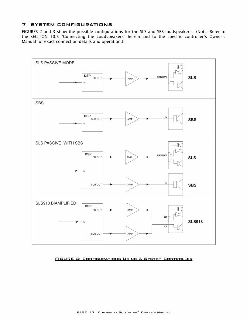
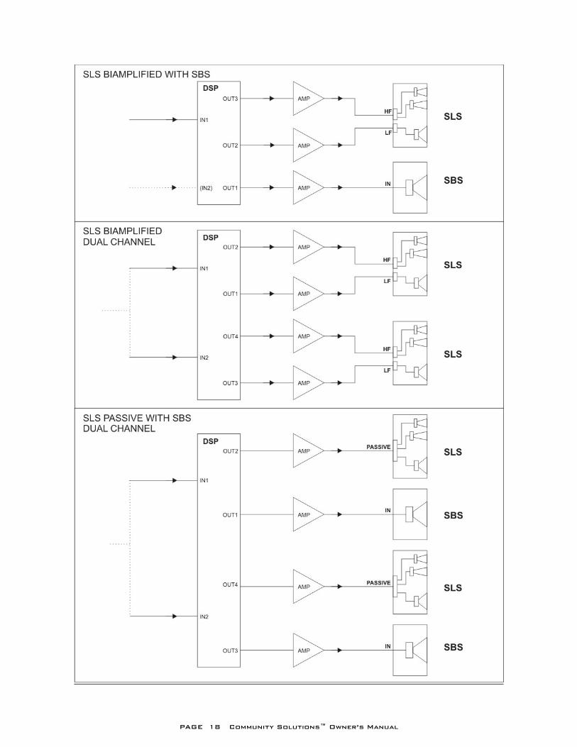
7 SYSTEM CONFIGURATIONS FIGURES 2 and 3 show the possible configurations for the SLS and SBS loudspeakers. (Note: Refer to the SECTION 10.5 “Connecting the Loudspeakers” herein and to the specific controller’s Owner’s Manual for exact connection details and operation.)
FIGURE 2: Configurations Using A System Controller
PAGE 18 Community Solutions™ Owner’s Manual

PAGE 19 Community Solutions™ Owner’s Manual
8 CHOOSING POWER AMPLIFICATION It is important to select the proper power amplifier output for the loudspeaker. To avoid the potential for damage and/or less than optimum performance you need to have enough amplifier power but not too much. The published power ratings for Community Solutions loudspeakers, as listed in the Technical Specifications in CHAPTER 16, are only applicable when the loudspeakers are used with an electronic system controller or processor. COMMUNITY’S WARRANTY CLEARLY STATES THAT “USE WITHOUT THE APPROPRIATE SYSTEM CONTROLLER IS CONSIDERED ABUSE AND VOIDS THE WARRANTY”. 8.1 General Considerations There are several things that must be considered when selecting an amplifier for a loudspeaker system. An obvious but misleading consideration is how loud the system needs to be. This should be determined, not by amplifier power, but by the correct choice of the loudspeaker or number of loudspeakers based on their maximum usable acoustic output ratings. Note that maximum ratings for many loudspeakers do not take distortion into account. Community’s maximum output ratings are realistically usable because the distortion is well within acceptable levels. In this regard, be conservative. A loudspeaker system that is more capable than needed will always perform well. A system that is not capable enough will likely need to be pushed hard enough to distort and may fail. 8.2 Amplifier Power For Use with An Electronic Controller Assuming the correct loudspeakers have been chosen for the application, the best choice of power amplifier is a simple consideration when using a dynamic electronic controller for Community Solutions SLS and SBS. To take full advantage of the electronic loudspeaker controller, a certain minimum power is required. Too little power will essentially bypass the protection function of the controller by allowing the amplifier to clip before the controller’s protection circuits are activated. This can result in damaged loudspeakers, in spite of the sophisticated electronic protection. (Refer to SECTION 13.3 “Using Lower Power Amplifiers”.) Based on these considerations, the choice of power amplifier size should be based on the power rating of the loudspeaker. The nominal impedance of the loudspeaker (e.g. 8 Ohm or 4 Ohm) must be used in determining an amplifier’s output specification from its manufacturer. Community specifies two power ratings: “RMS” and “Program”. The “RMS” rating is a measure of the thermal limitations of the loudspeaker, while the “Program” rating is a measure of the loudspeaker’s capability to reproduce speech and music. THE RECOMMENDED POWER AMPLIFIER IS ONE WHOSE RATED POWER APPROXIMATELY MATCHES THE “PROGRAM” POWER RATING OF THE LOUDSPEAKER. This will provide two important benefits:
1. The controller and PowerSense circuitry will operate properly to protect the loudspeaker. 2. With average power inputs near the loudspeaker’s RMS rating, peak power outputs of 7 dB to
10 dB will be available for the dynamic (peak) content of audio signals.
PAGE 20 Community Solutions™ Owner’s Manual
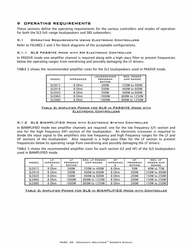
9 OPERATING REQUIREMENTS These sections define the operating requirements for the various controllers and modes of operation for both the SLS full-range loudspeakers and SBS subwoofers. 9.1 Operating Requirements Using Electronic Controllers Refer to FIGURES 2 and 3 for block diagrams of the acceptable configurations. 9.1.1 SLS PASSIVE Mode with AN Electronic Controller In PASSIVE mode one amplifier channel is required along with a high-pass filter to prevent frequencies below the operating ranges from overdriving and possibly damaging the LF drivers. TABLE 2 shows the recommended amplifier sizes for the SLS loudspeakers used in PASSIVE mode.
MODEL
IMPEDANCE
LOUDSPEAKER PROGRAM RATING
REC. POWER AMP RANGE
SLS915 8 Ohm 300W 250W to 400W SLS918 8 Ohm 500W 400W to 600W SLS920 8 Ohm 500W 400W to 600W SLS960 8 Ohm 1000W 800W to 1250W SLS980 8 Ohm 1000W 800W to 1250W
Table 2: Amplifier Power for SLS in PASSIVE Mode with
Electronic Controllers 9.1.2 SLS BIAMPLIFIED Mode with Electronic System Controller In BIAMPLIFIED mode two amplifier channels are required: one for the low frequency (LF) section and one for the high frequency (HF) section of the loudspeaker. An electronic crossover is required to divide the input signal to the amplifiers into low frequency and high frequency ranges for the LF and HF sections of the loudspeaker. Also required is a high-pass filter for the LF section to prevent frequencies below its operating range from overdriving and possibly damaging the LF drivers. TABLE 3 shows the recommended amplifier sizes for each section (LF and HF) of the SLS loudspeakers used in BIAMPLIFIED mode.
MODEL
LF IMPEDANC
E
LF PROGRAM RATING
REC. LF POWER AMP RANGE
HF IMPEDANC
E
HF PROGRAM RATING
REC. HF POWER AMP
RANGE
SLS915 8 Ohm 300W 250W to 400W 8 Ohm 50W 40W to 75W SLS918 8 Ohm 500W 400W to 600W 8 Ohm 300W 250W to 400WSLS920 8 Ohm 500W 400W to 600W 8 Ohm 200W 150W to 250WSLS960 8 Ohm 1000W 800W to 1250W 8 Ohm 200W 150W to 250WSLS980 8 Ohm 1000W 800W to 1250W 8 Ohm 200W 150W to 250W
Table 3: Amplifier Power for SLS in BIAMPLIFIED Mode with Controller
PAGE 21 Community Solutions™ Owner’s Manual
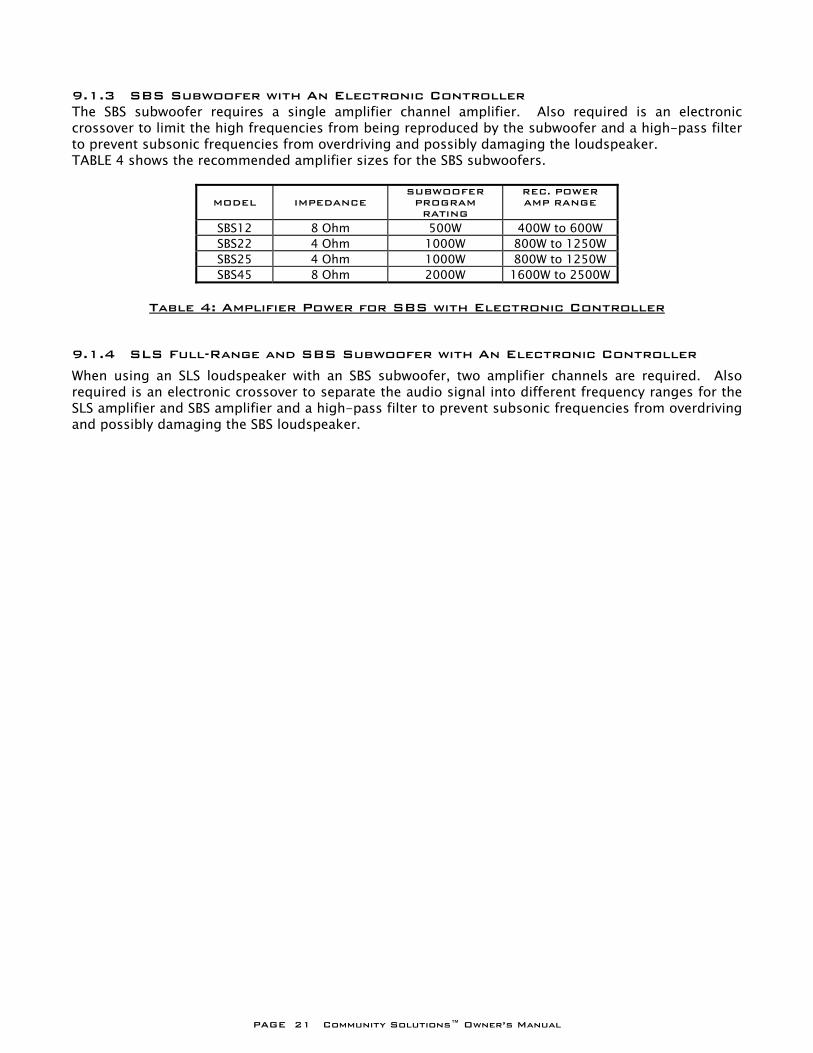
9.1.3 SBS Subwoofer with An Electronic Controller The SBS subwoofer requires a single amplifier channel amplifier. Also required is an electronic crossover to limit the high frequencies from being reproduced by the subwoofer and a high-pass filter to prevent subsonic frequencies from overdriving and possibly damaging the loudspeaker. TABLE 4 shows the recommended amplifier sizes for the SBS subwoofers.
MODEL
IMPEDANCE
SUBWOOFER PROGRAM RATING
REC. POWER AMP RANGE
SBS12 8 Ohm 500W 400W to 600W SBS22 4 Ohm 1000W 800W to 1250W SBS25 4 Ohm 1000W 800W to 1250W SBS45 8 Ohm 2000W 1600W to 2500W
Table 4: Amplifier Power for SBS with Electronic Controller
9.1.4 SLS Full-Range and SBS Subwoofer with An Electronic Controller When using an SLS loudspeaker with an SBS subwoofer, two amplifier channels are required. Also required is an electronic crossover to separate the audio signal into different frequency ranges for the SLS amplifier and SBS amplifier and a high-pass filter to prevent subsonic frequencies from overdriving and possibly damaging the SBS loudspeaker.
PAGE 22 Community Solutions™ Owner’s Manual
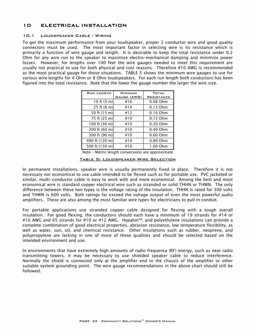
10 ELECTRICAL INSTALLATION 10.1 Loudspeaker Cable / Wiring To get the maximum performance from your loudspeaker, proper 2 conductor wire and good quality connectors must be used. The most important factor in selecting wire is its resistance which is primarily a function of wire gauge and length. It is desirable to keep the total resistance under 0.2 Ohm for any wire run to the speaker to maximize electro-mechanical damping and minimize power losses. However, for lengths over 100 feet the wire gauges needed to meet this requirement are usually not practical to use for both physical and cost reasons. Therefore #10 AWG is recommended as the most practical gauge for those situations. TABLE 5 shows the minimum wire gauges to use for various wire lengths for 4 Ohm or 8 Ohm loudspeakers. For each run length both conductors has been figured into the total resistance. Note that the lower the gauge number the larger the wire size.
Run Length Minimum Gauge (AWG)
Total Resistance
10 ft (3 m) #16 0.08 Ohm 25 ft (8 m) #14 0.13 Ohm
50 ft (15 m) #12 0.16 Ohm 75 ft (25 m) #10 0.15 Ohm
100 ft (30 m) #10 0.20 Ohm 200 ft (60 m) #10 0.40 Ohm 300 ft (90 m) #10 0.60 Ohm
400 ft (120 m) #10 0.80 Ohm 500 ft (150 m) #10 1.00 Ohm Note – Metric length conversions are approximate
Table 5: Loudspeaker Wire Selection In permanent installations, speaker wire is usually permanently fixed in place. Therefore it is not necessary nor economical to use cable intended to be flexed such as for portable use. PVC jacketed or similar, multi-conductor cable is easy to work with and more economical. Among the best and most economical wire is standard copper electrical wire such as stranded or solid THHN or THWN. The only difference between these two types is the voltage rating of the insulation. THHN is rated for 300 volts and THWN is 600 volts. Both ratings far exceed the voltage output of even the most powerful audio amplifiers. These are also among the most familiar wire types for electricians to pull in conduit. For portable applications use stranded copper cable designed for flexing with a tough overall insulation. For good flexing, the conductors should each have a minimum of 19 strands for #14 or #16 AWG and 65 strands for #10 or #12 AWG. Hypalon™, and polyethylene insulations can provide a complete combination of good electrical properties, abrasion resistance, low temperature flexibility, as well as water, sun, oil, and chemical resistance. Other insulations such as rubber, neoprene, and polypropylene are lacking in one of more of these qualities and should be selected based on the intended environment and use. In environments that have extremely high amounts of radio frequency (RF) energy, such as near radio transmitting towers, it may be necessary to use shielded speaker cable to reduce interference. Normally the shield is connected only at the amplifier end to the chassis of the amplifier or other suitable system grounding point. The wire gauge recommendations in the above chart should still be followed.
PAGE 23 Community Solutions™ Owner’s Manual
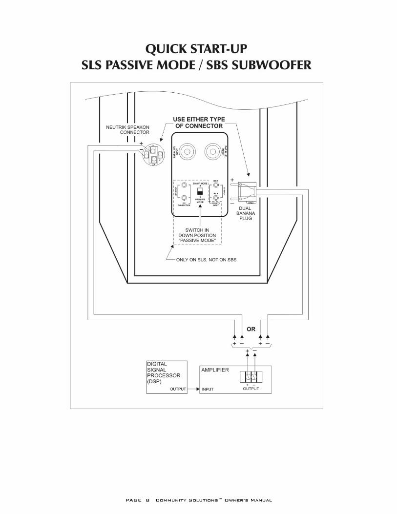
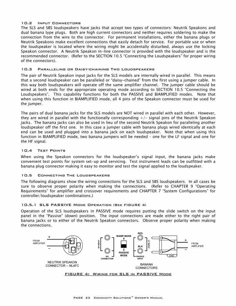
10.2 Input Connectors The SLS and SBS loudspeakers have jacks that accept two types of connectors: Neutrik Speakons and dual banana type plugs. Both are high current connectors and neither requires soldering to make the connection from the wire to the connector. For permanent installations, either the banana plugs or Neutrik Speakons make excellent connections that easily detach for service. For portable use or when the loudspeaker is located where the wiring might be accidentally disturbed, always use the locking Speakon connector. A Neutrik Speakon in-line connector is provided with the loudspeaker and is the recommended connector. (Refer to the SECTION 10.5 “Connecting the Loudspeakers” for proper wiring of the connectors). 10.3 Paralleling or Daisy-chaining Two Loudspeakers The pair of Neutrik Speakon input jacks for the SLS models are internally wired in parallel. This means that a second loudspeaker can be paralleled or “daisy-chained” from the first using a jumper cable. In this way both loudspeakers will operate off the same amplifier channel. The jumper cable should be wired at both ends for the appropriate operating mode according to SECTION 10.5 “Connecting the Loudspeakers”. This capability functions for both the PASSIVE and BIAMPLIFIED modes. Note that when using this function in BIAMPLIFIED mode, all 4 pins of the Speakon connector must be used for the jumper. The pairs of dual banana jacks for the SLS models are NOT wired in parallel with each other. However, they are wired in parallel with the functionally corresponding +/– signal pins of the Neutrik Speakon jacks. The banana jacks can also be used in lieu of the second Neutrik Speakon for paralleling another loudspeaker off the first one. In this case a jumper cable with banana plugs wired identically at each end can be used and plugged into a banana jack on each loudspeaker. Note that when using this function in BIAMPLIFIED mode, two banana jumpers will be needed – one for the LF signal and one for the HF signal. 10.4 Test Points When using the Speakon connectors for the loudspeaker’s signal input, the banana jacks make convenient test points for system set-up and servicing. Test instrument leads can be outfitted with a banana plug connector making it easy to monitor and test the signal applied to the loudspeaker. 10.5 Connecting The Loudspeakers The following diagrams show the wiring connections for the SLS and SBS loudspeakers. In all cases be sure to observe proper polarity when making the connections. (Refer to CHAPTER 9 “Operating Requirements” for amplifier and crossover requirements and CHAPTER 7 “System Configurations” for controller/loudspeaker combinations.) 10.5.1 SLS PASSIVE Mode Operation (See FIGURE 4) Operation of the SLS loudspeakers in PASSIVE mode requires putting the slide switch on the input panel in the “Passive” (down) position. The input connections are made either to the right pair of banana jacks or to either of the Neutrik Speakon connectors. Observe proper polarity when making the connections.
FIGURE 4: Wiring for SLS in PASSIVE Mode
PAGE 24 Community Solutions™ Owner’s Manual
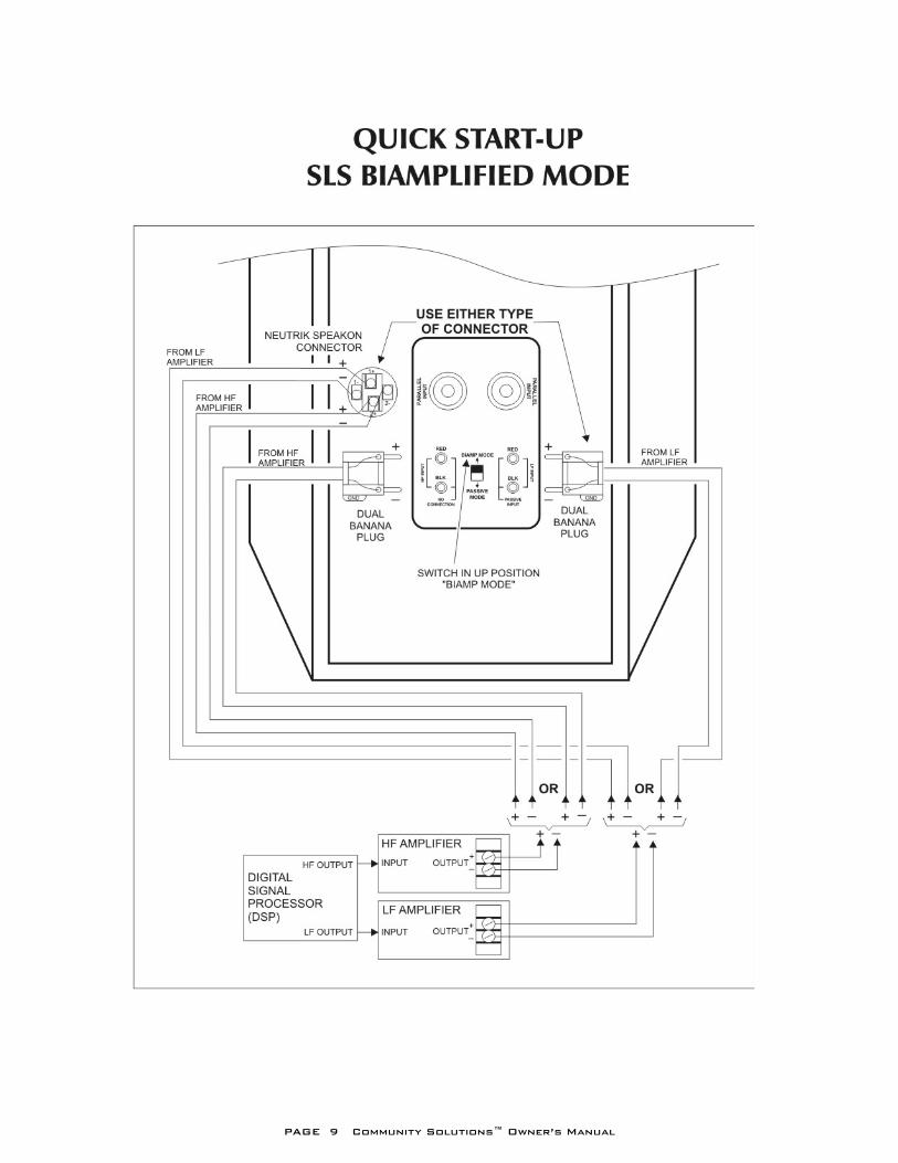
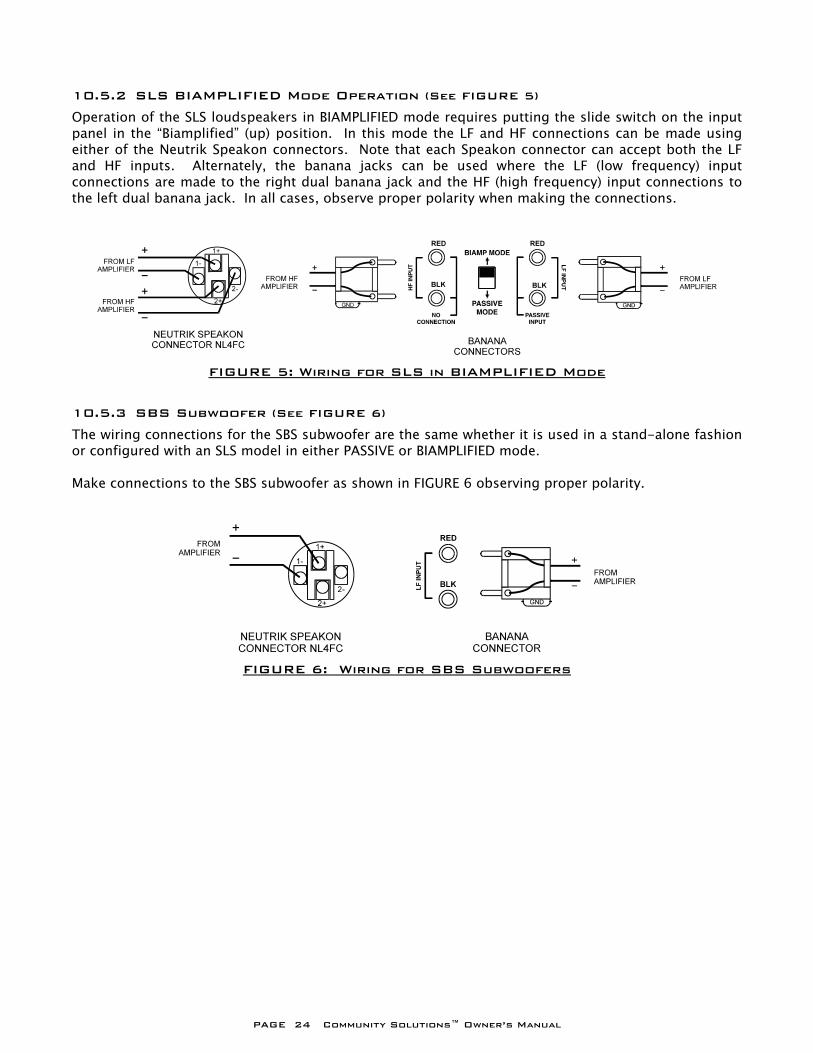
10.5.2 SLS BIAMPLIFIED Mode Operation (See FIGURE 5) Operation of the SLS loudspeakers in BIAMPLIFIED mode requires putting the slide switch on the input panel in the “Biamplified” (up) position. In this mode the LF and HF connections can be made using either of the Neutrik Speakon connectors. Note that each Speakon connector can accept both the LF and HF inputs. Alternately, the banana jacks can be used where the LF (low frequency) input connections are made to the right dual banana jack and the HF (high frequency) input connections to the left dual banana jack. In all cases, observe proper polarity when making the connections.
10.5.3 SBS Subwoofer (See FIGURE 6) The wiring connections for the SBS subwoofer are the same whether it is used in a stand-alone fashion or configured with an SLS model in either PASSIVE or BIAMPLIFIED mode. Make connections to the SBS subwoofer as shown in FIGURE 6 observing proper polarity.
FIGURE 5: Wiring for SLS in BIAMPLIFIED Mode
FIGURE 6: Wiring for SBS Subwoofers
PAGE 25 Community Solutions™ Owner’s Manual
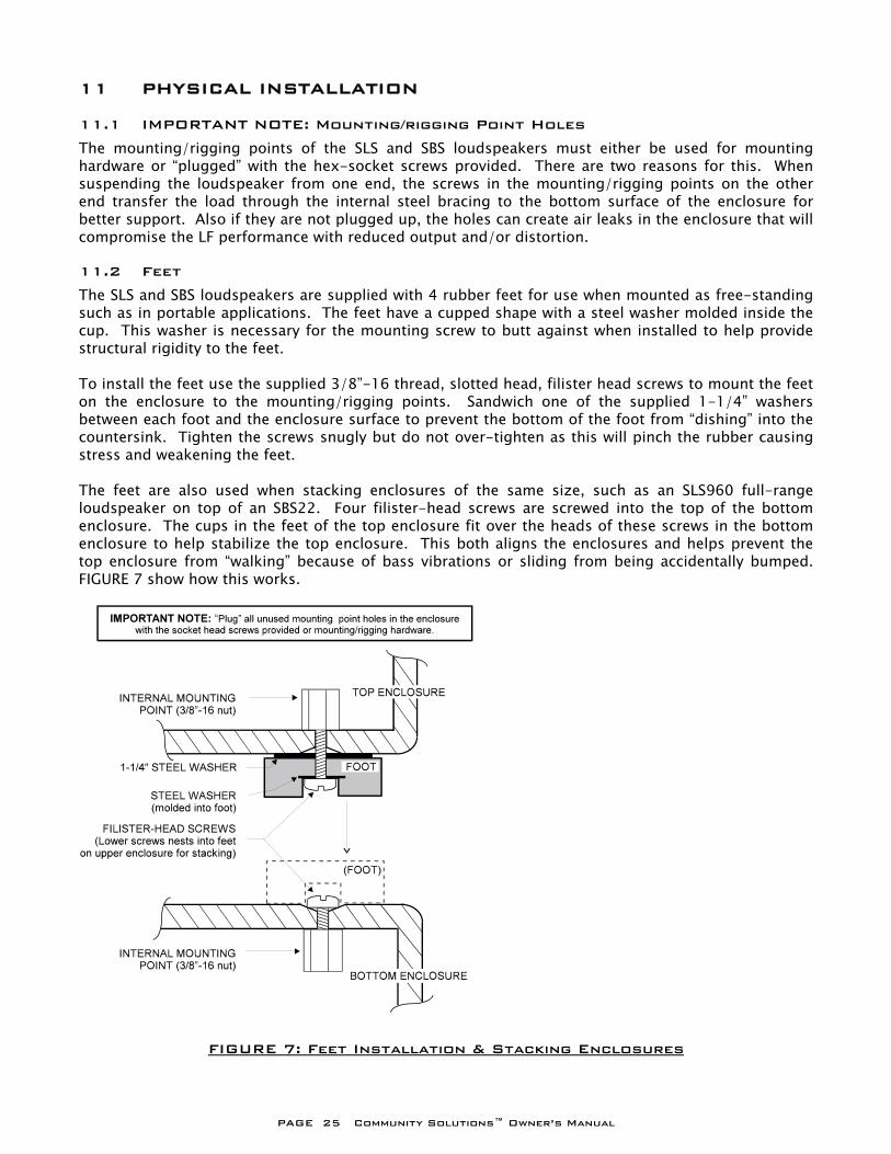
11 PHYSICAL INSTALLATION 11.1 IMPORTANT NOTE: Mounting/rigging Point Holes The mounting/rigging points of the SLS and SBS loudspeakers must either be used for mounting hardware or “plugged” with the hex-socket screws provided. There are two reasons for this. When suspending the loudspeaker from one end, the screws in the mounting/rigging points on the other end transfer the load through the internal steel bracing to the bottom surface of the enclosure for better support. Also if they are not plugged up, the holes can create air leaks in the enclosure that will compromise the LF performance with reduced output and/or distortion. 11.2 Feet The SLS and SBS loudspeakers are supplied with 4 rubber feet for use when mounted as free-standing such as in portable applications. The feet have a cupped shape with a steel washer molded inside the cup. This washer is necessary for the mounting screw to butt against when installed to help provide structural rigidity to the feet. To install the feet use the supplied 3/8”-16 thread, slotted head, filister head screws to mount the feet on the enclosure to the mounting/rigging points. Sandwich one of the supplied 1-1/4” washers between each foot and the enclosure surface to prevent the bottom of the foot from “dishing” into the countersink. Tighten the screws snugly but do not over-tighten as this will pinch the rubber causing stress and weakening the feet. The feet are also used when stacking enclosures of the same size, such as an SLS960 full-range loudspeaker on top of an SBS22. Four filister-head screws are screwed into the top of the bottom enclosure. The cups in the feet of the top enclosure fit over the heads of these screws in the bottom enclosure to help stabilize the top enclosure. This both aligns the enclosures and helps prevent the top enclosure from “walking” because of bass vibrations or sliding from being accidentally bumped. FIGURE 7 show how this works.
FIGURE 7: Feet Installation & Stacking Enclosures
PAGE 26 Community Solutions™ Owner’s Manual
11.3 Front Grille All SLS and SBS loudspeakers have a 16 gauge perforated steel grille on the face of the enclosures to provide a finished appearance and to protect the drivers. The grille is essentially acoustically transparent with a TI (Transparency Index) rating of over 13,700, where 10,000 is considered essentially transparent. The grille is painted using a powder coating process that bonds the paint to the steel. This prevents the paint from easily chipping and the resulting matte finish reduces reflection of ambient light sources. If desired for cosmetic purposes, the grille may be painted another color using standard, non-bridging enamel paint. Spray painting is recommended. The grille is a pan shape with a soft, PVC gasket fitted around its edge that serves several purposes. It provides a snug fit for the grille into the front recess of the enclosure. This light clamping action has the added effect of helping damp the grille to keep it from resonating. The gasket is also used to retain the grille cloth on the -WHT models or a custom grille cloth. 11.3.1 Removing/Installing the Grille Removal of the grille is accomplished by unscrewing the 4 #6 x 1-1/2” retainer screws in each corner then pulling the grille away from the face of the enclosure to release the Quick-lock pads that help support it (Refer to FIGURE 8). A small Allen wrench or similar tool can be used to hook the grille through one of the perforations to aid in pulling it away from the enclosure. In the case of the -WHT models with a grille cloth, carefully pull on the grille near a corner by sliding an Allen wrench or similar tool in the gap between the enclosure and grille. Turn the wrench to hook the grille from behind and pull it away from the enclosure. To reinstall the grille make sure that the grille is correctly oriented so the Quick-lock pads on the grille and enclosure will mate. Press the grille in place applying firm pressure on each of the pads to firmly interlock them and replace the 4 corner retainer screws. CAUTION:
When the loudspeaker is suspended or mounted overhead the grille must remain permanently fastened in place so that it does not become detached. Make sure all corner retainer screws are properly installed and tightened.
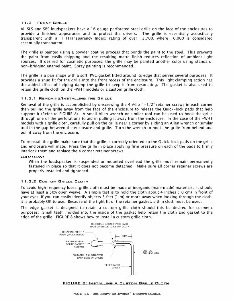
11.3.2 Custom Grille Cloth To avoid high frequency loses, grille cloth must be made of inorganic (man-made) materials. It should have at least a 50% open weave. A simple test is to hold the cloth about 4 inches (10 cm) in front of your eyes. If you can easily identify objects 3 feet (1 m) or more away when looking through the cloth, it is probably OK to use. Because of the tight fit of the retainer gasket, a thin cloth must be used. The edge gasket is designed to retain a custom grille cloth should this be desired for cosmetic purposes. Small teeth molded into the inside of the gasket help retain the cloth and gasket to the edge of the grille. FIGURE 8 shows how to install a custom grille cloth.
FIGURE 8: Installing A Custom Grille Cloth
PAGE 27 Community Solutions™ Owner’s Manual
11.4 Enclosure Finish The enclosures are finished with a water-based acrylic paint (trade-named Polene™). If desired, this finish can be painted over with a custom color using any standard, water-based, DTM acrylic paint without the need for any special surface preparation. FE models are finished in black, hand-laminated fiberglass. If it is desired to paint these enclosures with a custom color, they must be sanded and then washed with a solvent (such as turpentine or denatured alcohol) prior to painting. A spray-on acrylic paint will yield the best results but even then, results may be unpredictable in terms of the quality, durability and longevity of the new finish. 11.5 Mounting and Rigging WARNING:
Mounting or rigging loudspeakers is a serious endeavor and requires an experienced professional. Improper installations may result in damage, injury or death. For this reason, no loudspeaker should be mounted or suspended overhead unless the method has been approved by a registered Professional Structural Engineer.
WARNING: NEVER USE THE HANDLES FOR SUSPENDING THE LOUDSPEAKER. They are neither designed nor rated for this purpose.
CAUTION: All fixed hardware used for overhead mounting or suspension should be designed, tested, and certified for its intended use with a minimum design factor or 5:1. A minimum design factor or 8:1 should be employed for any component which may be subject to continuous wear or friction, such as moving wire rope. A design factor is the ratio between the structural failure point and the loading to be applied to the component.
CAUTION: Routine inspections and maintenance should be performed on any mounting or rigging system. Any parts found to have deterioration, excessive fatigue, or excessive wear should be removed from service immediately.
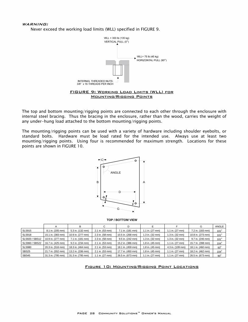
11.5.1 Design Factor for Working Load Limits (WLL)) The WLL limits listed for SLS and SBS mounting/rigging points and pull-back points have a design factor of 20:1. 11.5.2 Mounting/Rigging Points All SLS and SBS loudspeakers have internal, captive 3/8”-16 threaded nuts for suspending or permanent mounting. Four are located on the enclosure top and four on the bottom. Each of the 8 mounting/rigging points has a Working Load Limit (WLL rated for 300 lb. (136.1 kg) vertical pull and 75 lb. (34 kg) horizontal pull. Refer to FIGURE 9 for pull directions. Community’s WLL ratings include a 20:1 safety factor.
PAGE 28 Community Solutions™ Owner’s Manual
WARNING: Never exceed the working load limits (WLL) specified in FIGURE 9.
The top and bottom mounting/rigging points are connected to each other through the enclosure with internal steel bracing. Thus the bracing in the enclosure, rather than the wood, carries the weight of any under-hung load attached to the bottom mounting/rigging points. The mounting/rigging points can be used with a variety of hardware including shoulder eyebolts, or standard bolts. Hardware must be load rated for the intended use. Always use at least two mounting/rigging points. Using four is recommended for maximum strength. Locations for these points are shown in FIGURE 10.
FIGURE 9: Working Load Limits (WLL) for Mounting/Rigging Points
Figure 10: Mounting/Rigging Point Locations
ANGLE
AB
C
D
E
FG
TOP / BOTTOM VIEW
A B C D E F G ANGLE SLS915 8.1 in. (205 mm) 5.3 in. (132 mm) 2.1 in. (53 mm) 7.1 in. (181 mm) 1.1 in. (27 mm) 1.1 in. (27 mm) 7.2 in. (183 mm) 101o
SLS918 15.1 in. (383 mm) 10.9 in. (277 mm) 2.3 in. (58 mm) 10.5 in. (268 mm) 1.3 in. (32 mm) 1.3 in. (32 mm) 10.8 in. (273 mm) 101o
SLS920 / SBS12 10.9 in. (277 mm) 7.1 in. (181 mm) 2.3 in. (58 mm) 9.5 in. (242 mm) 1.3 in. (32 mm) 1.3 in. (32 mm) 9.7 in. (246 mm) 101o
SLS960 / SBS22 16.7 in. (425 mm) 9.2 in. (234 mm) 2.1 in. (53 mm) 15.2 in. (386 mm) 1.8 in. (45 mm) 1.1 in. (27 mm) 15.7 In. (398 mm) 104o
SLS980 20.3 in. (516 mm) 18.3 in. (464 mm) 2.1 in. (53 mm) 18.1 in. (459 mm) 1.8 in. (45 mm) 4.3 in. (109 mm) 18.1 in. (460 mm) 93o
SBS25 21.7 in. (552 mm) 13.2 in. (336 mm) 2.1 in. (53 mm) 17.7 in. (450 mm) 1.8 in. (45 mm) 1.1 in. (27 mm) 18.2 in. (462 mm) 104o
SBS45 31.3 in. (795 mm) 31.3 in. (795 mm) 1.1 in. (27 mm) 26.5 in. (673 mm) 1.1 in. (27 mm) 1.1 in. (27 mm) 26.5 in. (673 mm) 90o
PAGE 29 Community Solutions™ Owner’s Manual
11.5.3 Using Only Two Mounting/Rigging Points If only the two rear mounting/rigging points are used, the loudspeaker will hang with a down-angle of approximately 30 degrees. This may be ideal for many situations. If less down-angle is needed, four mounting/rigging points should be used with the front mounting/rigging points used to pull up the front of the enclosure to the desired down-angle. Alternately you can use the front two mounting/rigging points and use a pull-back to set the desired down-angle. (Refer to “Pull-back Capability”.) When using two mounting/rigging points, be sure the rated loads for the mounting rigging points are not exceeded. Refer to SECTION 11.5.4 for de-rating the mounting/rigging points when using them at an angle. 11.5.4 De-Rating the Mounting/Rigging Points Using the mounting/rigging points at an angle will de-rate the WLL for each point according to the following formula:
WLL = Cosine (Angle) x 300. The Angle is in degrees from vertical pull. NOTE: This formula is only valid for pull angles up to 75 degrees. From 75 degrees to 90 degrees the WLL remains as 75 lb. (34 kg).
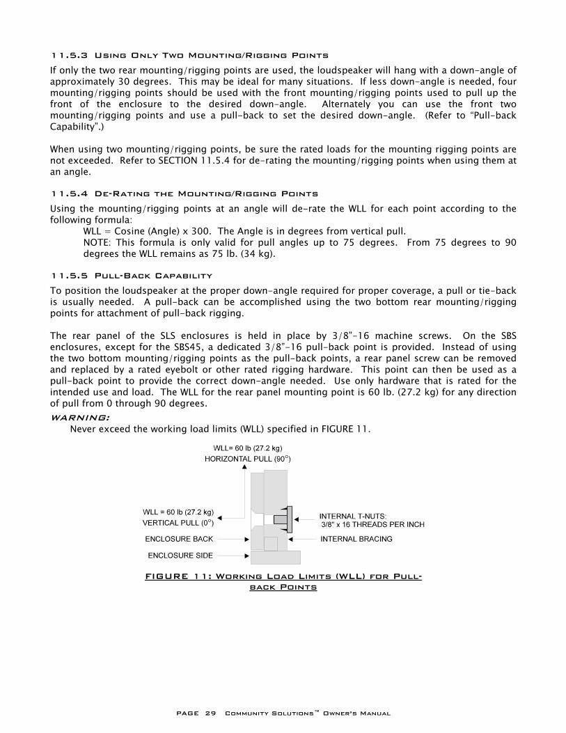
11.5.5 Pull-Back Capability To position the loudspeaker at the proper down-angle required for proper coverage, a pull or tie-back is usually needed. A pull-back can be accomplished using the two bottom rear mounting/rigging points for attachment of pull-back rigging. The rear panel of the SLS enclosures is held in place by 3/8”-16 machine screws. On the SBS enclosures, except for the SBS45, a dedicated 3/8”-16 pull-back point is provided. Instead of using the two bottom mounting/rigging points as the pull-back points, a rear panel screw can be removed and replaced by a rated eyebolt or other rated rigging hardware. This point can then be used as a pull-back point to provide the correct down-angle needed. Use only hardware that is rated for the intended use and load. The WLL for the rear panel mounting point is 60 lb. (27.2 kg) for any direction of pull from 0 through 90 degrees. WARNING: Never exceed the working load limits (WLL) specified in FIGURE 11.
FIGURE 11: Working Load Limits (WLL) for Pull-
back Points
PAGE 30 Community Solutions™ Owner’s Manual
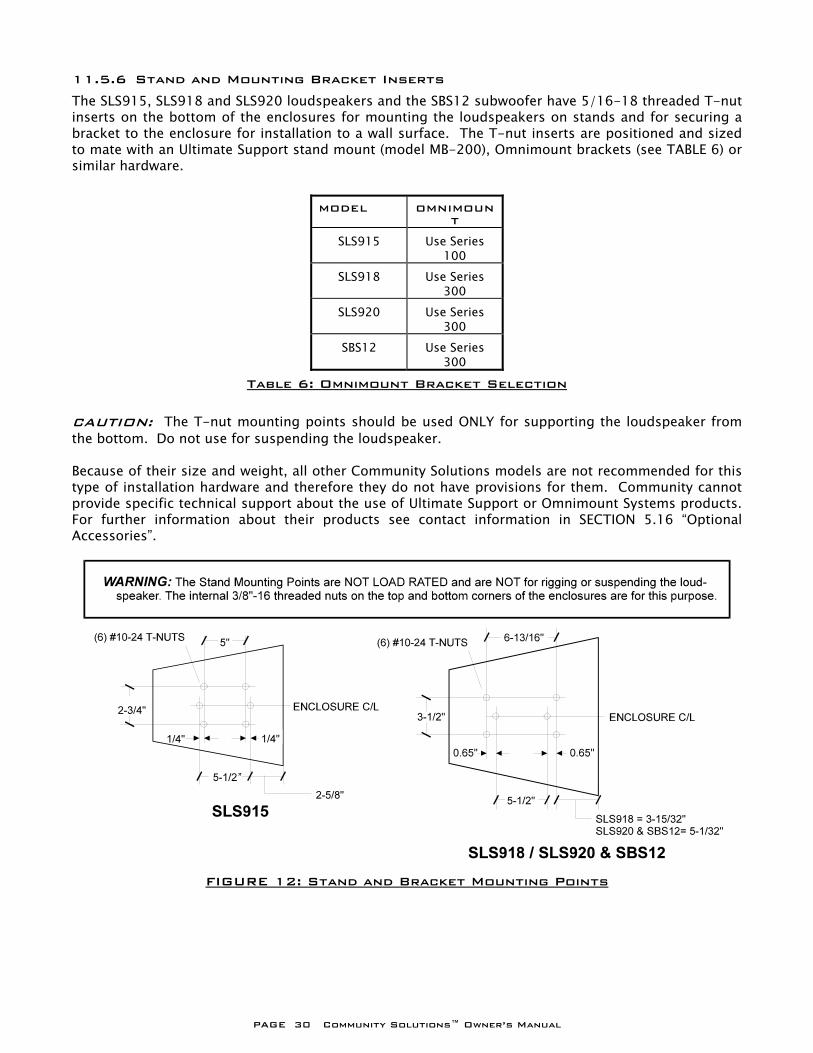
11.5.6 Stand and Mounting Bracket Inserts The SLS915, SLS918 and SLS920 loudspeakers and the SBS12 subwoofer have 5/16-18 threaded T-nut inserts on the bottom of the enclosures for mounting the loudspeakers on stands and for securing a bracket to the enclosure for installation to a wall surface. The T-nut inserts are positioned and sized to mate with an Ultimate Support stand mount (model MB-200), Omnimount brackets (see TABLE 6) or similar hardware.
MODEL OMNIMOUNT
SLS915 Use Series 100
SLS918 Use Series 300
SLS920 Use Series 300
SBS12 Use Series 300
Table 6: Omnimount Bracket Selection CAUTION: The T-nut mounting points should be used ONLY for supporting the loudspeaker from the bottom. Do not use for suspending the loudspeaker. Because of their size and weight, all other Community Solutions models are not recommended for this type of installation hardware and therefore they do not have provisions for them. Community cannot provide specific technical support about the use of Ultimate Support or Omnimount Systems products. For further information about their products see contact information in SECTION 5.16 “Optional Accessories”.
FIGURE 12: Stand and Bracket Mounting Points
PAGE 31 Community Solutions™ Owner’s Manual
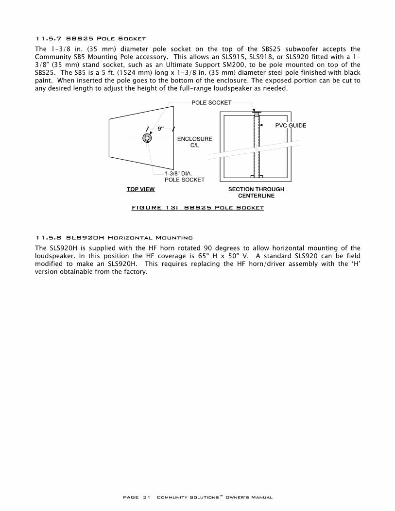
11.5.7 SBS25 Pole Socket The 1-3/8 in. (35 mm) diameter pole socket on the top of the SBS25 subwoofer accepts the Community SB5 Mounting Pole accessory. This allows an SLS915, SLS918, or SLS920 fitted with a 1-3/8” (35 mm) stand socket, such as an Ultimate Support SM200, to be pole mounted on top of the SBS25. The SB5 is a 5 ft. (1524 mm) long x 1-3/8 in. (35 mm) diameter steel pole finished with black paint. When inserted the pole goes to the bottom of the enclosure. The exposed portion can be cut to any desired length to adjust the height of the full-range loudspeaker as needed. 11.5.8 SLS920H Horizontal Mounting The SLS920H is supplied with the HF horn rotated 90 degrees to allow horizontal mounting of the loudspeaker. In this position the HF coverage is 65º H x 50º V. A standard SLS920 can be field modified to make an SLS920H. This requires replacing the HF horn/driver assembly with the ‘H’ version obtainable from the factory.
FIGURE 13: SBS25 Pole Socket
PAGE 32 Community Solutions™ Owner’s Manual
12 ACOUSTICAL ADJUSTMENTS Once the loudspeaker has been set-up or installed and connected according to the configuration you need, it is ready for acoustical adjustments. 12.1 Initial Testing The following procedures are designed to prevent damage to the loudspeaker during initial testing of the system.
1. Before powering up any equipment, turn down the input level controls on the power amplifiers and set other level controls to nominal operating positions. If you don’t know what those positions are, setting sliders about half-way up and rotary controls to their 12 o’clock or half-way position is usually a safe bet.
2. Turn on all the electronics for the system by following the proper sequence for power up that is universally accepted for professional audio systems. This means turn on the system in “signal chain order” starting with the input equipment and continuing in order along the chain with the power amplifiers being the last items to be powered up. This avoids electronic start-up transients or spikes that some equipment generates. These spikes generally consist of a DC (direct current) pulse that can be intense enough to overload subsequent equipment, including the loudspeaker, and cause instantaneous and permanent damage to that equipment. This procedure should be followed EVERY TIME a system is turned on.
NOTE: When turning off a system, do it in the reverse order, beginning with the power amplifiers first and the input equipment last.
3. Apply an input signal to the system. This could be a test signal or program material from a tape, CD, or tuner. Using equipment level indicators, a voltmeter, and/or a test headset verify that the signal chain is operating properly up to the input of the power amplifier(s). You may have to re-adjust controls as set in step 2 to get normal signal levels through to the amplifier input(s).
4. If the signal chain tests OK, turn up the input levels to the amplifier(s) and you should hear your input signal reproduced through the loudspeaker. It should be clean and clear. If using biamplification and/or subwoofers the sound may not be balanced between the high and low frequencies, but this is corrected in final tuning.
5. If all is well you are ready for the final adjustments to the system.
12.2 Final Adjustments There are two primary things to consider when making final adjustments on a system: electronic gain structure and loudspeaker level balancing. The gain structure of a system will determine the dynamic range of a system or the ratio of the softest to loudest usable sounds. The softest sounds will be limited by the amount of system noise and the loudest sounds by noticeable distortion or clipping. Loudspeaker level balancing includes only those systems where there is more than one loudspeaker. This includes systems where loudspeakers reproduce different frequency ranges (e.g. biamplified loudspeakers or a full-range loudspeaker with a subwoofer) or systems where multiple loudspeakers reproduce the same frequency range, (e.g. arrays of multiple loudspeakers or main and delayed loudspeakers). 12.3 Electronic Gain Structure Detailed information on how to set electronic gain structure is beyond the scope of this manual. However the following are VERY general guidelines that may be helpful.
PAGE 33 Community Solutions™ Owner’s Manual
1. As a minimum, you need to use at least a voltmeter along with the maximum output voltage specification for each piece of electronics. The preferable tool is an oscilloscope that can be used to observe the signal directly. If neither of these are available, you can use the level or clipping indicators on each piece of equipment in the signal chain. Without some method of determining the clipping point for each piece of equipment, you cannot expect to optimize the gain structure.
2. Before setting gain structure disconnect the loudspeaker(s) from the amplifiers. Do not disconnect the sense lines for any electronic controllers in the system.
3. The basic procedure is to use a test signal (a sine wave signal is ideal) and set the first piece of equipment in the signal chain (usually the mixer) so it is just below maximum voltage output as read on the voltmeter or on equipment’s output meter or just below clipping as observed on the oscilloscope. Without changing this signal level adjust the level controls on each piece of equipment following, including the power amplifiers, so it is just below its maximum output. You will find that the input level controls on the power amplifier will end up being set anywhere from 10 dB to over 20 dB of attenuation.
NOTES: a. Due to differences in the capabilities of devices in the signal chain, it may not be
possible to achieve the results exactly as stated. b. Gain structure should be set after any equalization is set for the system so that any
boosts (which reduce headroom in the equalizer) are taken into account. c. For each device, make sure it is the output and not the input that is clipping. d. Always make sure that the electronic controllers go into limiting prior to anything else in
the system going into clipping. In this way the controller’s limiter, rather than a clipped signal somewhere else in the signal chain, will control the system’s maximum output.
4. Remove the test signal, turn off all equipment and reconnect the loudspeaker(s) and the
system is ready for level balancing, assuming you have more than one loudspeaker. If you have only one loudspeaker the system should be ready for use.
12.3.1 Residual Noise The SLS and SBS loudspeakers have high sensitivities which mean that they produce a relatively high output for a given electrical input. This includes the residual electronic noise of an audio system. By setting gain structure properly and using high quality professional electronics, this noise should be at or near inaudibility. Among the noisier electronic devices are 16 bit digital devices such as some signal delays. They have signal to noise ratios that are only 90 dB. However, if the gain structure is set correctly this means that, for example, if the system can produce 120 dB SPL at maximum output, the residual noise should be about 30 dB SPL. This would be acceptable for a quiet recording studio. If residual noise is a problem, gain structure is usually the culprit – it is never the loudspeakers. 12.4 Level Balancing Once the system gain structure is set, the level balances can be adjusted. This may mean the levels between HF and LF sections of a biamplified loudspeaker, a full-range loudspeaker to subwoofer level, levels between multiple loudspeakers, or between main and delayed loudspeaker array. The idea is to make the system sound the best it can without using any equalization. This may be done using acoustic test equipment such as an RTA (real-time analyzer), TEF™ analyzer or similar. You must always determine the final level balance by listening to a variety of known program material. Level balancing can also be done entirely by ear if acoustic test equipment is not available. In any case, the preferred method of adjusting levels for balancing is to use the amplifier input level controls. IMPORTANT: In order to maintain the system’s dynamic range that was maximized by setting the proper gain structure, DO NOT TURN UP THE INPUT LEVEL CONTROLS OF ANY OF THE AMPLIFIERS. For
PAGE 34 Community Solutions™ Owner’s Manual
example, if you decide that a subwoofer is not loud enough, do not turn up the input level control of its amplifier. Instead, turn down the input level of the full-range loudspeaker’s amplifier. 12.5 Equalization Once level balances are set, you can then equalize the loudspeaker(s), if necessary. Community loudspeakers, used with an electronic controller, are optimized for highly accurate and well balanced reproduction “out-of-the-box”. Generally, equalization should only be needed to eliminate difficult feedback frequencies or to adapt the system to a difficult acoustic environment. You should not need more than a few dB of boost or cut equalization for any particular range of frequencies. The best equalization techniques involve cutting rather than boosting frequencies. Refer to the SECTION 13.5 “External Equalization” for more information. 12.6 Final Results Once the above procedures are followed, your loudspeaker should reproduce audio cleanly, clearly and with all frequencies in good balance. Noise should not be audible and you should be able to drive at least one amplifier/controller in the system to its maximum output on normal program material with no significant distortion or other undesirable sound.

PAGE 35 Community Solutions™ Owner’s Manual
13 OPERATING PRECAUTIONS The following sections detail certain operating precautions for the loudspeaker which will aid in achieving and maintaining its maximum performance and reliability. They also include important information for situations and usage outside the basic set-up and operation described in the previous sections. 13.1 PowerSense DDP Cautions The crossovers for the SLS models incorporate PowerSense DDP (Dynamic Driver Protection) circuitry that automatically provides thermal and over-current protection for the individual drivers. The SBS subwoofers do NOT have PowerSense circuitry. The PowerSense circuits are designed to work in conjunction with an electronic controller, or some other type of electronic limiter. Without the combination of passive and electronic protection, the loudspeaker system is more susceptible to damage and outright failure. This combination provides significant but not absolute protection from damage. For example, neither the PowerSense circuitry nor electronic limiting can provide protection from continual overdriving or from too small an amplifier being driven into heavy clipping. (Refer to FIGURE 14: “Effects of Amplifier Clipping” and to SECTION 13.3 “Using Low Power Amplifiers”.) 13.1.1 Operating Modes and PowerSense DDP The PowerSense DDP circuits function in both the PASSIVE and BIAMPLIFIED modes for all SLS models. This means that in BIAMPLIFIED mode, both the HF and LF sections have their own PowerSense protection. The only exception to this is the 12” (305 mm) LF driver in the SLS918. The SBS subwoofers do NOT have PowerSense circuitry because they do not have an internal crossover. Protection, as well as the required crossover function, must be supplied by external electronics. CAUTION:
Do not operate the SBS subwoofers without an appropriate high-pass filter. The high-pass filter attenuates low frequencies that are below the useful frequency range of the subwoofer. Such frequencies can cause excessive cone excursion and possible driver damage.
13.1.2 PowerSense DDP Circuit Operation (SBS subwoofers do not have this circuit)
This proprietary circuitry can help ensure that your SLS loudspeakers will perform at their best and keep performing year after year. It provides not only a measure of protection but gives clear visual and audible indications to the operator of excessive power input. The PowerSense circuit actually has three levels of protection (See note below For SLS915 and SLS918). For short term excessive power inputs occurring at high frequencies, the excess power to the HF driver is absorbed by HPCCRs (High Positive Current Coefficient Resistors). These are wired in series with the high frequency driver and convert excessive power to light and heat. When these HPCCRs emit light, their impedance goes up and thus reduces the power input to the HF driver. When activated, flashes of light from the HPCCRs can be seen through the bass ports of the loudspeaker alerting the operator of the excessive power input. Very occasional flashing (once in several seconds) is OK. If flashing occurs more often than this, it indicates that the volume should be immediately reduced. This level of protection has little effect on the system output as these HPCCRs are always in circuit and gradually absorb excessive power in a way that is audibly similar to a compressor circuit with a “soft” knee. For longer term or more excessive input, the power to the mid frequency driver or to the entire system will be reduced by current sensitive relays. These make up two additional levels of protection. One relay, when opened, puts a set of HPCCRs in series with the mid frequency driver and the other, when opened, puts a different set of HPCCRs in series with the entire system. These sets of HPCCRs are only put in series with the signal as a result of excessive current causing its associated relay to open. When the signal is switched to pass through the HPCCRs, the loudspeaker’s output volume will be reduced

PAGE 36 Community Solutions™ Owner’s Manual
by several dB, quickly and noticeably. How much reduction will depend on the amount and frequency range of the excessive power. As a further indication of the operation of either of these circuits, a brighter, steadier light will be seen through the bass ports than for the HF driver protection. The open relay will then reset itself after several seconds, depending on the amount of excessive power, and the loudspeaker’s output volume will return to normal. However, if the excessive power condition continues, the relay will re-open and reduce the power and volume again. This will have the effect of the system volume cutting in and out and is a clear warning of excessive power and the need to reduce the input level to the system. Note: The SLS915 and SLS918 have only two sets of HPCCRs, one for the high frequency driver and one for the dual 6.5” (165 mm) drivers. The set for the dual 6.5” drivers is relay activated. There is no PowerSense DDP protection for the SLS918 12” (305 mm) driver. WARNING:
Continued cycling of the relays can result in their failure. This will either lock the system up in the reduced volume mode or, if the contacts fuse, bypass the HPCCR protection. Either condition can result in damage to the loudspeakers or crossover components. When either the HPCCRs for the HF driver flash, or the mid frequency or overall system protection relay is activated, it means the loudspeaker is being protected, but only to a point. Therefore, any of these conditions should be considered an immediate warning that the power input is excessive. The volume level of the sound system should be reduced to a point where the HF driver protection is activated only once every several seconds at the most.
13.2 Use Without Electronic Controller All SLS and SBS loudspeakers will function without electronic control. However, this will provide neither optimum performance from, nor any protection for the loudspeakers as Community’s published specifications are established using electronic control. Bear in mind that Community’s warranty provides insurance against manufacturing defects but does not cover loudspeakers that have been damaged by excessive power input or other abuse – THIS INCLUDES OPERATION WITHOUT ELECTRONIC CONTROL. 13.3 Using Lower Power Amplifiers (Refer to the CHAPTER 8 “Choosing Power Amplification”) When using an amplifier whose rated power output is below that recommended for the loudspeaker listed in CHAPTER 9 “Operating Requirements”, the following precautions should be observed. Driver damage and failure occurs most often when a loudspeaker is used with too small an amplifier. The amplifier itself will be overdriven before the loudspeaker is or before the protection circuitry in the controller is activated. The result is that the loudspeaker receives a badly distorted signal known as amplifier clipping (refer to FIGURE 14). The characteristics of a clipped signal are such that it easily can damage any speaker component even if the power output is below the power rating of the loudspeaker. NEITHER THE POWERSENSE DDP NOR THE CONTROLLER CIRCUITRY CAN PROTECT THE LOUDSPEAKER FROM DAMAGE DUE TO POWER AMPLIFIER CLIPPING. When operating an SLS loudspeaker with a lower power amplifier and without any sort of electronic limiting protection, ensure that the amplifier’s limits are not exceeded. Most amplifiers have some type of indicator that shows when it is clipping. Keeping the signal level below this point will usually prevent loudspeaker damage or failure. High frequency drivers are very intolerant of clipping. The SBS models contain no driver protection and must rely on external protection circuitry provided by an external limiter. If no limiter is present, use an amplifier that is matched to the loudspeaker’s Program power rating. For the reasons stated above, do not allow the amplifier to be driven into clipping. FIGURE 14 describes and depicts clipping.
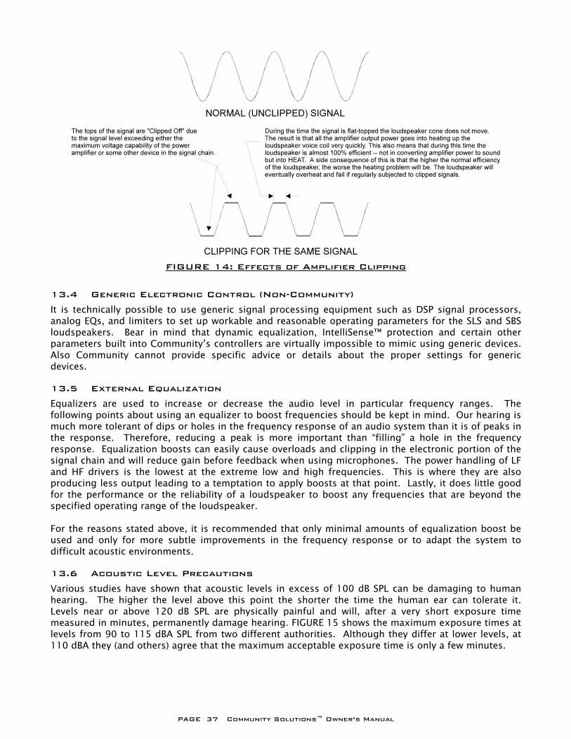
PAGE 37 Community Solutions™ Owner’s Manual
13.4 Generic Electronic Control (Non-Community) It is technically possible to use generic signal processing equipment such as DSP signal processors, analog EQs, and limiters to set up workable and reasonable operating parameters for the SLS and SBS loudspeakers. Bear in mind that dynamic equalization, IntelliSense™ protection and certain other parameters built into Community’s controllers are virtually impossible to mimic using generic devices. Also Community cannot provide specific advice or details about the proper settings for generic devices. 13.5 External Equalization Equalizers are used to increase or decrease the audio level in particular frequency ranges. The following points about using an equalizer to boost frequencies should be kept in mind. Our hearing is much more tolerant of dips or holes in the frequency response of an audio system than it is of peaks in the response. Therefore, reducing a peak is more important than “filling” a hole in the frequency response. Equalization boosts can easily cause overloads and clipping in the electronic portion of the signal chain and will reduce gain before feedback when using microphones. The power handling of LF and HF drivers is the lowest at the extreme low and high frequencies. This is where they are also producing less output leading to a temptation to apply boosts at that point. Lastly, it does little good for the performance or the reliability of a loudspeaker to boost any frequencies that are beyond the specified operating range of the loudspeaker. For the reasons stated above, it is recommended that only minimal amounts of equalization boost be used and only for more subtle improvements in the frequency response or to adapt the system to difficult acoustic environments. 13.6 Acoustic Level Precautions Various studies have shown that acoustic levels in excess of 100 dB SPL can be damaging to human hearing. The higher the level above this point the shorter the time the human ear can tolerate it. Levels near or above 120 dB SPL are physically painful and will, after a very short exposure time measured in minutes, permanently damage hearing. FIGURE 15 shows the maximum exposure times at levels from 90 to 115 dBA SPL from two different authorities. Although they differ at lower levels, at 110 dBA they (and others) agree that the maximum acceptable exposure time is only a few minutes.
FIGURE 14: Effects of Amplifier Clipping
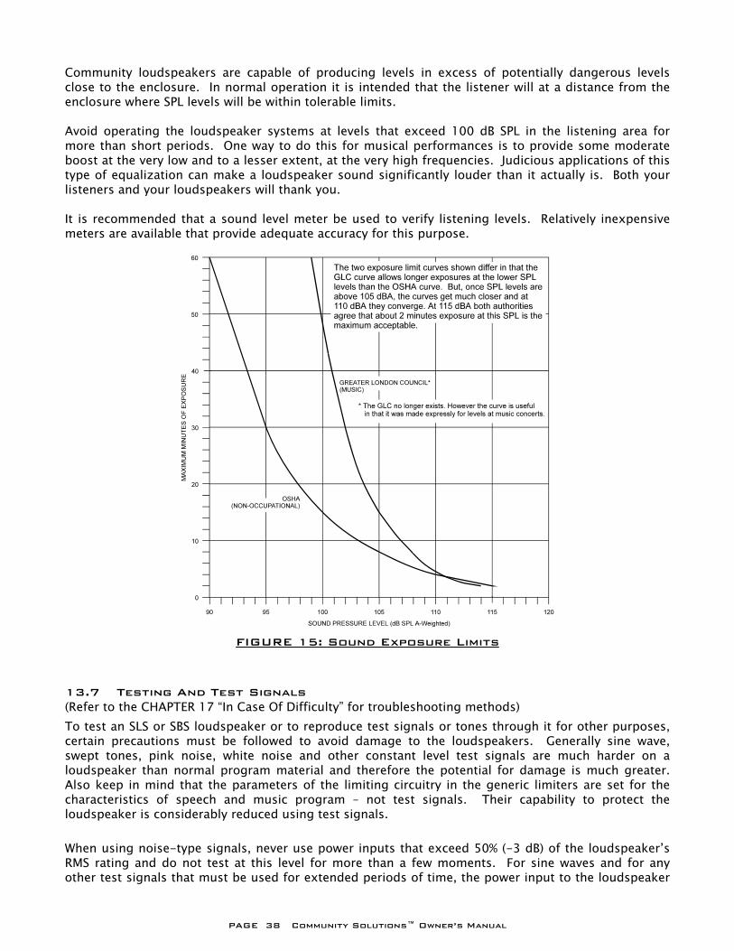
PAGE 38 Community Solutions™ Owner’s Manual
Community loudspeakers are capable of producing levels in excess of potentially dangerous levels close to the enclosure. In normal operation it is intended that the listener will at a distance from the enclosure where SPL levels will be within tolerable limits. Avoid operating the loudspeaker systems at levels that exceed 100 dB SPL in the listening area for more than short periods. One way to do this for musical performances is to provide some moderate boost at the very low and to a lesser extent, at the very high frequencies. Judicious applications of this type of equalization can make a loudspeaker sound significantly louder than it actually is. Both your listeners and your loudspeakers will thank you. It is recommended that a sound level meter be used to verify listening levels. Relatively inexpensive meters are available that provide adequate accuracy for this purpose.
13.7 Testing And Test Signals (Refer to the CHAPTER 17 “In Case Of Difficulty” for troubleshooting methods) To test an SLS or SBS loudspeaker or to reproduce test signals or tones through it for other purposes, certain precautions must be followed to avoid damage to the loudspeakers. Generally sine wave, swept tones, pink noise, white noise and other constant level test signals are much harder on a loudspeaker than normal program material and therefore the potential for damage is much greater. Also keep in mind that the parameters of the limiting circuitry in the generic limiters are set for the characteristics of speech and music program – not test signals. Their capability to protect the loudspeaker is considerably reduced using test signals. When using noise-type signals, never use power inputs that exceed 50% (-3 dB) of the loudspeaker’s RMS rating and do not test at this level for more than a few moments. For sine waves and for any other test signals that must be used for extended periods of time, the power input to the loudspeaker
FIGURE 15: Sound Exposure Limits

PAGE 39 Community Solutions™ Owner’s Manual
should be kept below 10% (-10 dB) of the loudspeaker’s RMS rating to ensure the loudspeaker will not be damaged.
PAGE 40 Community Solutions™ Owner’s Manual
13.8 Microphone Feedback One of the more potentially damaging signals in an audio system is microphone feedback. This usually results in a high volume level, single-tone signal (essentially a sine wave) being reproduced through the loudspeakers. This kind of signal can quickly damage the drivers and therefore the situation should be corrected as quickly as possible. To avoid this situation the following approaches can be tried. It will be necessary to increase the gain for the system in order to “test” if there is any improvement in the gain-before-feedback margin as adjustments are made. During a performance the main recourse to stop feedback or ringing is to reduce the volume for the offending microphone or, if this cannot be quickly determined, reduce the volume of the entire system. The following list is in the general order of preference of what to do first. Note that using equalization is the last thing to do.
1. Use directional microphones (cardiod-types) that have well controlled pick-up patterns. 2. Keep microphones close to the sound sources. The further away they are the more gain that is
needed. 3. Use similar quality microphones. Major problems can be caused by just one poor microphone
that is sensitive to feedback. 4. Use as few microphones as possible. The amount of gain-before-feedback decreases as the
number of “open” microphones increases. 5. When possible, use direct inputs, such as direct boxes, contact pickups, and line feeds from
instrument amplifiers. This will reduce the number of live microphones. 6. Always keep the microphones behind the plane of the loudspeakers and/or aimed away from
them. 7. Reposition the microphone to provide better feedback rejection. Sometimes moving it only a
few inches or re-orienting it will suffice. 8. Mute any microphones when they are not being used. 9. Reverse the polarity of a microphone that is feedback sensitive. 10. Try a different type of microphone in place of one that is feedback sensitive. 11. Use sound absorbing materials like rugs, packing blankets, or sound isolating panels to reduce
sound reflections in hard surfaced stage environments. 12. Use a graphic equalizer, parametric equalizer, or notch filter to reduce the level of frequencies
that are prone to feedback. For best results, it is recommended that a graphic equalizer used for controlling feedback have filter bandwidths of 1/3 octave or narrower.
PAGE 41 Community Solutions™ Owner’s Manual
14 OPERATING PRECAUTIONS FOR THE SLS918 The SLS918 is essentially an SLS915 combined with an SBS12 subwoofer into one enclosure. When used in PASSIVE mode it has similar performance to an SLS915/SBS12 combination but does not require an electronic crossover. It is important to note that the PowerSense DDP protection circuit for the SLS918 LF driver is bypassed in BIAMPLIFIED mode. When using an electronic controller in this mode electronic protection is provided by the controller. If these controllers are not used, it is recommended that an external limiter be used to provide electronic protection to help prevent possible damage from excess power. Set the limiter to provide at least a 10:1 compression ratio and set its threshold to below amplifier clipping. The amplifier power output rating should be within the range recommended in SECTION 9.1.2
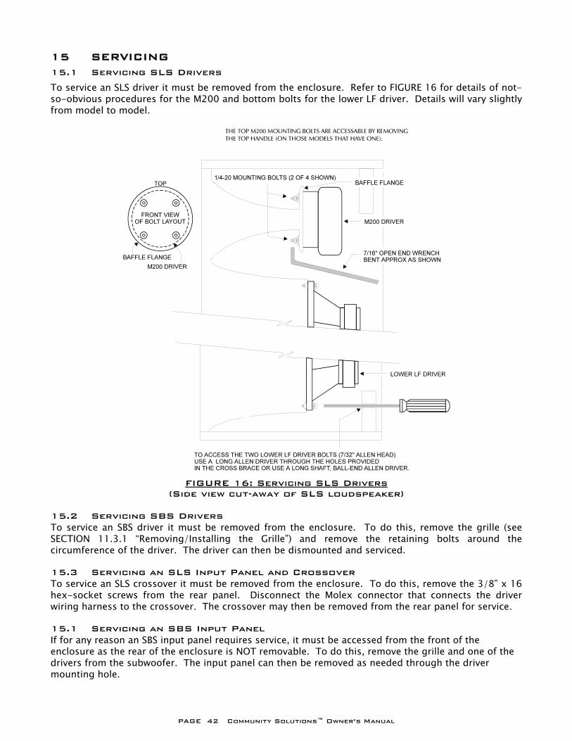
PAGE 42 Community Solutions™ Owner’s Manual
15 SERVICING 15.1 Servicing SLS Drivers To service an SLS driver it must be removed from the enclosure. Refer to FIGURE 16 for details of not-so-obvious procedures for the M200 and bottom bolts for the lower LF driver. Details will vary slightly from model to model.
15.2 Servicing SBS Drivers To service an SBS driver it must be removed from the enclosure. To do this, remove the grille (see SECTION 11.3.1 “Removing/Installing the Grille”) and remove the retaining bolts around the circumference of the driver. The driver can then be dismounted and serviced. 15.3 Servicing an SLS Input Panel and Crossover To service an SLS crossover it must be removed from the enclosure. To do this, remove the 3/8” x 16 hex-socket screws from the rear panel. Disconnect the Molex connector that connects the driver wiring harness to the crossover. The crossover may then be removed from the rear panel for service. 15.1 Servicing an SBS Input Panel If for any reason an SBS input panel requires service, it must be accessed from the front of the enclosure as the rear of the enclosure is NOT removable. To do this, remove the grille and one of the drivers from the subwoofer. The input panel can then be removed as needed through the driver mounting hole.
FIGURE 16: Servicing SLS Drivers
(Side view cut-away of SLS loudspeaker)
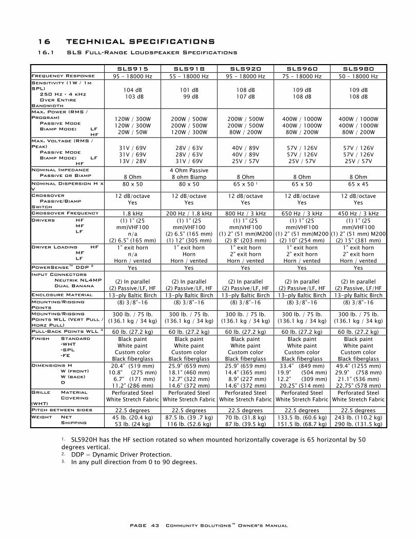
PAGE 43 Community Solutions™ Owner’s Manual
16 TECHNICAL SPECIFICATIONS 16.1 SLS Full-Range Loudspeaker Specifications
SLS915 SLS918 SLS920 SLS960 SLS980 Frequency Response 95 - 18000 Hz 55 - 18000 Hz 95 - 18000 Hz 75 - 18000 Hz 50 - 18000 Hz Sensitivity (1W / 1m SPL) 250 Hz - 4 kHz Over Entire Bandwidth
104 dB 103 dB
101 dB 99 dB
108 dB 107 dB
109 dB 108 dB
109 dB 108 dB
Max. Power (RMS / Program) Passive Mode Biamp Mode: LF HF
120W / 300W 120W / 300W 20W / 50W
200W / 500W 200W / 500W 120W / 300W
200W / 500W 200W / 500W 80W / 200W
400W / 1000W 400W / 1000W 80W / 200W
400W / 1000W 400W / 1000W 80W / 200W
Max. Voltage (RMS / Peak) Passive Mode Biamp Mode: LF HF
31V / 69V 31V / 69V 13V / 28V
28V / 63V 28V / 63V 31V / 69V
40V / 89V 40V / 89V 25V / 57V
57V / 126V 57V / 126V 25V / 57V
57V / 126V 57V / 126V 25V / 57V
Nominal Impedance Passive or Biamp
8 Ohm
4 Ohm Passive 8 ohm Biamp
8 Ohm
8 Ohm
8 Ohm
Nominal Dispersion H x V
80 x 50 80 x 50 65 x 50 1 65 x 50 65 x 45
Crossover Passive/Biamp Switch
12 dB/octave Yes
12 dB/octave Yes
12 dB/octave Yes
12 dB/octave Yes
12 dB/octave Yes
Crossover Frequency 1.8 kHz 200 Hz / 1.8 kHz 800 Hz / 3 kHz 650 Hz / 3 kHz 450 Hz / 3 kHz Drivers HF MF LF
(1) 1” (25 mm)VHF100
n/a (2) 6.5” (165 mm)
(1) 1” (25 mm)VHF100
(2) 6.5” (165 mm) (1) 12” (305 mm)
(1) 1” (25 mm)VHF100
(1) 2” (51 mm)M200(2) 8” (203 mm)
(1) 1” (25 mm)VHF100
(1) 2” (51 mm)M200 (2) 10” (254 mm)
(1) 1” (25 mm)VHF100
(1) 2” (51 mm) M200(2) 15” (381 mm)
Driver Loading HF MF LF
1” exit horn n/a
Horn / vented
1” exit horn Horn
Horn / vented
1” exit horn 2” exit horn
Horn / vented
1” exit horn 2” exit horn
Horn / vented
1” exit horn 2” exit horn
Horn / vented PowerSense™ DDP 2 Yes Yes Yes Yes Yes Input Connectors Neutrik NL4MP Dual Banana
(2) In parallel
(2) Passive/LF, HF
(2) In parallel
(2) Passive/LF, HF
(2) In parallel
(2) Passive/LF, HF
(2) In parallel
(2) Passive/LF, HF
(2) In parallel
(2) Passive, LF/HF Enclosure Material 13-ply Baltic Birch 13-ply Baltic Birch 13-ply Baltic Birch 13-ply Baltic Birch 13-ply Baltic Birch Mounting/Rigging Points
(8) 3/8”-16 (8) 3/8”-16 (8) 3/8”-16 (8) 3/8”-16 (8) 3/8”-16
Mounting/Rigging Points WLL (Vert Pull / Horz Pull)
300 lb. / 75 lb. (136.1 kg / 34 kg)
300 lb. / 75 lb. (136.1 kg / 34 kg)
300 lb. / 75 lb. (136.1 kg / 34 kg)
300 lb. / 75 lb. (136.1 kg / 34 kg)
300 lb. / 75 lb. (136.1 kg / 34 kg)
Pull-Back Points WLL 3 60 lb. (27.2 kg) 60 lb. (27.2 kg) 60 lb. (27.2 kg) 60 lb. (27.2 kg) 60 lb. (27.2 kg) Finish Standard -WHT -SPL -FE
Black paint White paint
Custom color Black fiberglass
Black paint White paint
Custom color Black fiberglass
Black paint White paint
Custom color Black fiberglass
Black paint White paint
Custom color Black fiberglass
Black paint White paint
Custom color Black fiberglass
Dimensions H W (front) W (back) D
20.4” (519 mm) 10.8” (275 mm) 6.7” (171 mm) 11.2” (286 mm)
25.9” (659 mm) 18.1” (460 mm) 12.7” (322 mm) 14.6” (372 mm)
25.9” (659 mm) 14.4” (365 mm) 8.9” (227 mm) 14.6” (372 mm)
33.4” (849 mm) 19.9” (504 mm) 12.2” (309 mm) 20.25” (514 mm)
49.4” (1255 mm) 29.9” (758 mm) 21.1” (536 mm) 22.75” (578 mm)
Grille Material Covering (WHT)
Perforated Steel White Stretch Fabric
Perforated Steel White Stretch Fabric
Perforated Steel White Stretch Fabric
Perforated Steel White Stretch Fabric
Perforated Steel White Stretch Fabric
Pitch between sides 22.5 degrees 22.5 degrees 22.5 degrees 22.5 degrees 22.5 degrees Weight Net Shipping
45 lb. (20.4 kg) 53 lb. (24 kg)
87.5 lb. (39 .7 kg) 116 lb. (52.6 kg)
70 lb. (31.8 kg) 87 lb. (39.5 kg)
133.5 lb. (60.6 kg) 151.5 lb. (68.7 kg)
243 lb. (110.2 kg) 290 lb. (131.5 kg)
1. SLS920H has the HF section rotated so when mounted horizontally coverage is 65 horizontal by 50 degrees vertical. 2. DDP = Dynamic Driver Protection. 3. In any pull direction from 0 to 90 degrees.
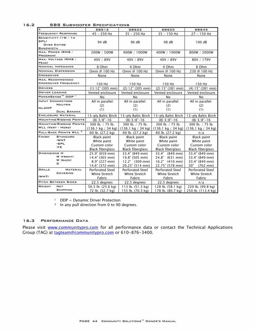
PAGE 44 Community Solutions™ Owner’s Manual
16.2 SBS Subwoofer Specifications 5 SBS12 SBS22 SBS25 SBS45 Frequency Response 45 - 250 Hz 35 - 250 Hz 35 - 150 Hz 27 - 150 Hz Sensitivity (1W / 1m SPL) Over Entire Bandwidth
94 dB
96 dB
98 dB
100 dB
Max. Power (RMS / Program)
200W / 500W 400W / 1000W 400W / 1000W 800W / 2000W
Max. Voltage (RMS / Peak)
40V / 89V 40V / 89V 40V / 89V 80V / 179V
Nominal Impedance 8 Ohm 4 Ohm 4 Ohm 8 Ohm Nominal Dispersion Omni @ 100 Hz Omni @ 100 Hz Omni @ 100 Hz 230 @ 100 Hz Crossover None None None None Max. Recommended Crossover Frequency
150 Hz
150 Hz
150 Hz
150 Hz
Drivers (1) 12” (305 mm) (2) 12” (305 mm) (2) 15” (381 mm) (4) 15” (381 mm)Driver Loading Vented enclosure Vented enclosure Vented enclosure Vented enclosure PowerSense™ DDP 1 No No No No Input Connectors Neutrik NL4MP Dual Banana
All in parallel: (2) (1)
All in parallel: (2) (1)
All in parallel: (2) (1)
All in parallel: (2) (1)
Enclosure Material 13-ply Baltic Birch 13-ply Baltic Birch 13-ply Baltic Birch 13-ply Baltic BirchMounting/Rigging Points (8) 3/8”-16 (8) 3/8”-16 (8) 3/8”-16 (8) 3/8”-16 Mounting/Rigging Points WLL (Vert / Horz)
300 lb. / 75 lb. (136.1 kg / 34 kg)
300 lb. / 75 lb. (136.1 kg / 34 kg)
300 lb. / 75 lb. (136.1 kg / 34 kg)
300 lb. / 75 lb. (136.1 kg / 34 kg)
Pull-Back Points WLL 2 60 lb. (27.2 kg) 60 lb. (27.2 kg) 60 lb. (27.2 kg) n/a Finish Standard -WHT -SPL -FE
Black paint White paint
Custom color Black fiberglass
Black paint White paint
Custom color Black fiberglass
Black paint White paint
Custom color Black fiberglass
Black paint White paint
Custom color Black fiberglass
Dimensions H W (front) W (back) D
25.9” (659 mm) 14.4” (365 mm) 8.9” (227 mm) 14.6” (372 mm)
33.4” (849 mm) 19.8” (505 mm) 12.2” (309 mm)20.25” (514 mm)
33.4” (849 mm) 24.8” (631 mm) 16.2” (410 mm) 22.75” (578 mm)
33.4” (849 mm) 33.4” (849 mm) 33.4” (849 mm) 30” (762 mm)
Grille Material Covering (WHT)
Perforated Steel White Stretch
Fabric
Perforated Steel White Stretch
Fabric
Perforated Steel White Stretch
Fabric
Perforated Steel White Stretch
Fabric Pitch Between Sides 22.5 degrees 22.5 degrees 22.5 degrees n/a Weight Net Shipping
56.5 lb. (25.6 kg) 72 lb. (32.7 kg)
113 lb. (51.3 kg) 155 lb. (70.3 kg)
128 lb. (58.1 kg) 178 lb. (80.7 kg)
220 lb. (99.8 kg) 250 lb. (113.4 kg)
1 DDP = Dynamic Driver Protection 2 In any pull direction from 0 to 90 degrees.
16.3 Performance Data
Please visit www.communitypro.com for all performance data or contact the Technical Applications Group (TAG) at [email protected] or 610-876-3400.
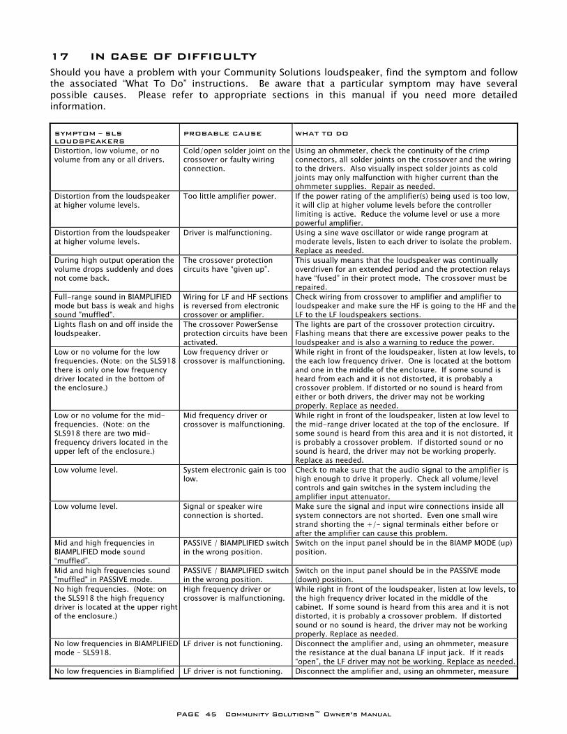
PAGE 45 Community Solutions™ Owner’s Manual
17 IN CASE OF DIFFICULTY Should you have a problem with your Community Solutions loudspeaker, find the symptom and follow the associated “What To Do” instructions. Be aware that a particular symptom may have several possible causes. Please refer to appropriate sections in this manual if you need more detailed information. SYMPTOM – SLS LOUDSPEAKERS
PROBABLE CAUSE WHAT TO DO
Distortion, low volume, or no volume from any or all drivers.
Cold/open solder joint on the crossover or faulty wiring connection.
Using an ohmmeter, check the continuity of the crimp connectors, all solder joints on the crossover and the wiring to the drivers. Also visually inspect solder joints as cold joints may only malfunction with higher current than the ohmmeter supplies. Repair as needed.
Distortion from the loudspeaker at higher volume levels.
Too little amplifier power. If the power rating of the amplifier(s) being used is too low, it will clip at higher volume levels before the controller limiting is active. Reduce the volume level or use a more powerful amplifier.
Distortion from the loudspeaker at higher volume levels.
Driver is malfunctioning. Using a sine wave oscillator or wide range program at moderate levels, listen to each driver to isolate the problem. Replace as needed.
During high output operation the volume drops suddenly and does not come back.
The crossover protection circuits have “given up”.
This usually means that the loudspeaker was continually overdriven for an extended period and the protection relays have “fused” in their protect mode. The crossover must be repaired.
Full-range sound in BIAMPLIFIED mode but bass is weak and highs sound "muffled".
Wiring for LF and HF sections is reversed from electronic crossover or amplifier.
Check wiring from crossover to amplifier and amplifier to loudspeaker and make sure the HF is going to the HF and the LF to the LF loudspeakers sections.
Lights flash on and off inside the loudspeaker.
The crossover PowerSense protection circuits have been activated.
The lights are part of the crossover protection circuitry. Flashing means that there are excessive power peaks to the loudspeaker and is also a warning to reduce the power.
Low or no volume for the low frequencies. (Note: on the SLS918 there is only one low frequency driver located in the bottom of the enclosure.)
Low frequency driver or crossover is malfunctioning.
While right in front of the loudspeaker, listen at low levels, to the each low frequency driver. One is located at the bottom and one in the middle of the enclosure. If some sound is heard from each and it is not distorted, it is probably a crossover problem. If distorted or no sound is heard from either or both drivers, the driver may not be working properly. Replace as needed.
Low or no volume for the mid-frequencies. (Note: on the SLS918 there are two mid-frequency drivers located in the upper left of the enclosure.)
Mid frequency driver or crossover is malfunctioning.
While right in front of the loudspeaker, listen at low level to the mid-range driver located at the top of the enclosure. If some sound is heard from this area and it is not distorted, it is probably a crossover problem. If distorted sound or no sound is heard, the driver may not be working properly. Replace as needed.
Low volume level. System electronic gain is too low.
Check to make sure that the audio signal to the amplifier is high enough to drive it properly. Check all volume/level controls and gain switches in the system including the amplifier input attenuator.
Low volume level. Signal or speaker wire connection is shorted.
Make sure the signal and input wire connections inside all system connectors are not shorted. Even one small wire strand shorting the +/– signal terminals either before or after the amplifier can cause this problem.
Mid and high frequencies in BIAMPLIFIED mode sound “muffled”.
PASSIVE / BIAMPLIFIED switch in the wrong position.
Switch on the input panel should be in the BIAMP MODE (up) position.
Mid and high frequencies sound "muffled" in PASSIVE mode.
PASSIVE / BIAMPLIFIED switch in the wrong position.
Switch on the input panel should be in the PASSIVE mode (down) position.
No high frequencies. (Note: on the SLS918 the high frequency driver is located at the upper right of the enclosure.)
High frequency driver or crossover is malfunctioning.
While right in front of the loudspeaker, listen at low levels, to the high frequency driver located in the middle of the cabinet. If some sound is heard from this area and it is not distorted, it is probably a crossover problem. If distorted sound or no sound is heard, the driver may not be working properly. Replace as needed.
No low frequencies in BIAMPLIFIED mode – SLS918.
LF driver is not functioning. Disconnect the amplifier and, using an ohmmeter, measure the resistance at the dual banana LF input jack. If it reads “open”, the LF driver may not be working. Replace as needed.
No low frequencies in Biamplified LF driver is not functioning. Disconnect the amplifier and, using an ohmmeter, measure
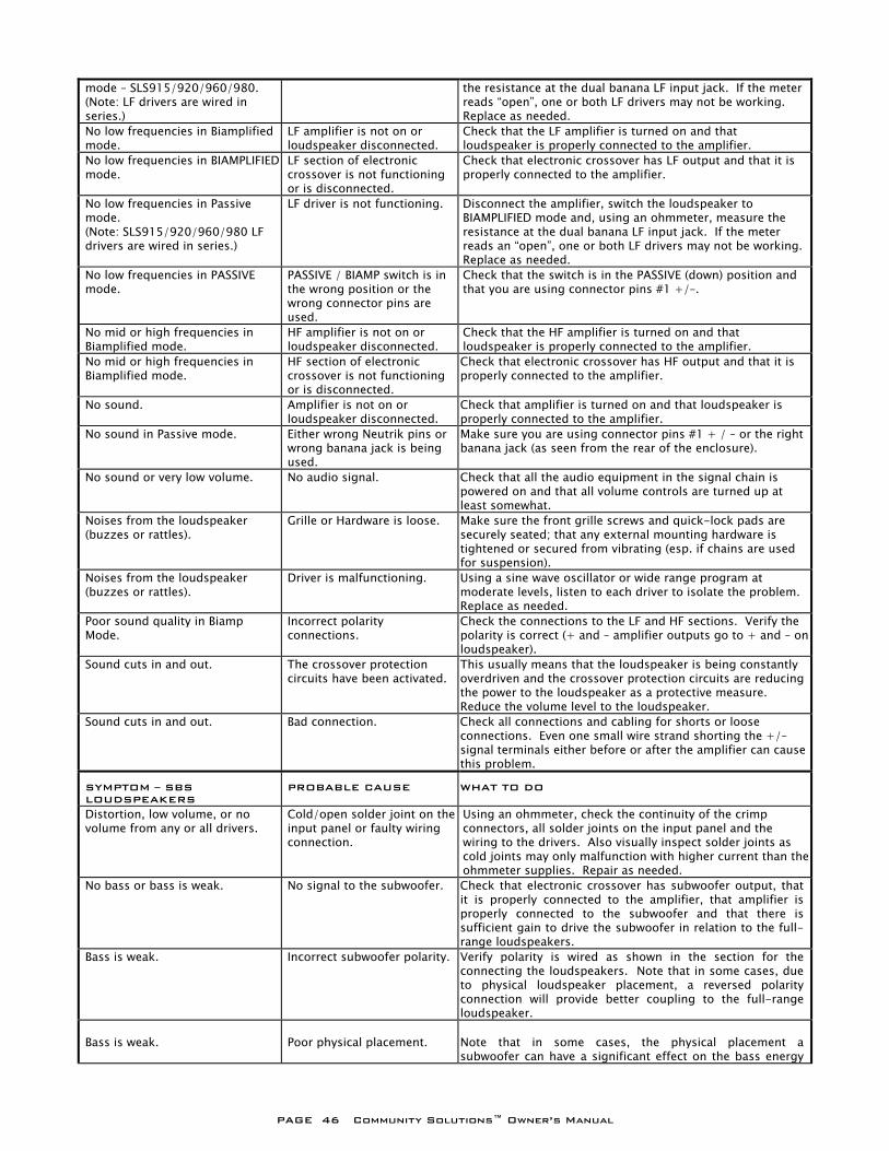
PAGE 46 Community Solutions™ Owner’s Manual
mode – SLS915/920/960/980. (Note: LF drivers are wired in series.)
the resistance at the dual banana LF input jack. If the meter reads “open”, one or both LF drivers may not be working. Replace as needed.
No low frequencies in Biamplified mode.
LF amplifier is not on or loudspeaker disconnected.
Check that the LF amplifier is turned on and that loudspeaker is properly connected to the amplifier.
No low frequencies in BIAMPLIFIED mode.
LF section of electronic crossover is not functioning or is disconnected.
Check that electronic crossover has LF output and that it is properly connected to the amplifier.
No low frequencies in Passive mode. (Note: SLS915/920/960/980 LF drivers are wired in series.)
LF driver is not functioning. Disconnect the amplifier, switch the loudspeaker to BIAMPLIFIED mode and, using an ohmmeter, measure the resistance at the dual banana LF input jack. If the meter reads an “open”, one or both LF drivers may not be working. Replace as needed.
No low frequencies in PASSIVE mode.
PASSIVE / BIAMP switch is in the wrong position or the wrong connector pins are used.
Check that the switch is in the PASSIVE (down) position and that you are using connector pins #1 +/–.
No mid or high frequencies in Biamplified mode.
HF amplifier is not on or loudspeaker disconnected.
Check that the HF amplifier is turned on and that loudspeaker is properly connected to the amplifier.
No mid or high frequencies in Biamplified mode.
HF section of electronic crossover is not functioning or is disconnected.
Check that electronic crossover has HF output and that it is properly connected to the amplifier.
No sound. Amplifier is not on or loudspeaker disconnected.
Check that amplifier is turned on and that loudspeaker is properly connected to the amplifier.
No sound in Passive mode. Either wrong Neutrik pins or wrong banana jack is being used.
Make sure you are using connector pins #1 + / – or the right banana jack (as seen from the rear of the enclosure).
No sound or very low volume. No audio signal. Check that all the audio equipment in the signal chain is powered on and that all volume controls are turned up at least somewhat.
Noises from the loudspeaker (buzzes or rattles).
Grille or Hardware is loose. Make sure the front grille screws and quick-lock pads are securely seated; that any external mounting hardware is tightened or secured from vibrating (esp. if chains are used for suspension).
Noises from the loudspeaker (buzzes or rattles).
Driver is malfunctioning. Using a sine wave oscillator or wide range program at moderate levels, listen to each driver to isolate the problem. Replace as needed.
Poor sound quality in Biamp Mode.
Incorrect polarity connections.
Check the connections to the LF and HF sections. Verify the polarity is correct (+ and – amplifier outputs go to + and – on loudspeaker).
Sound cuts in and out. The crossover protection circuits have been activated.
This usually means that the loudspeaker is being constantly overdriven and the crossover protection circuits are reducing the power to the loudspeaker as a protective measure. Reduce the volume level to the loudspeaker.
Sound cuts in and out. Bad connection. Check all connections and cabling for shorts or loose connections. Even one small wire strand shorting the +/– signal terminals either before or after the amplifier can cause this problem.
SYMPTOM – SBS LOUDSPEAKERS
PROBABLE CAUSE WHAT TO DO
Distortion, low volume, or no volume from any or all drivers.
Cold/open solder joint on the input panel or faulty wiring connection.
Using an ohmmeter, check the continuity of the crimp connectors, all solder joints on the input panel and the wiring to the drivers. Also visually inspect solder joints as cold joints may only malfunction with higher current than the ohmmeter supplies. Repair as needed.
No bass or bass is weak. No signal to the subwoofer. Check that electronic crossover has subwoofer output, that it is properly connected to the amplifier, that amplifier is properly connected to the subwoofer and that there is sufficient gain to drive the subwoofer in relation to the full-range loudspeakers.
Bass is weak. Incorrect subwoofer polarity. Verify polarity is wired as shown in the section for the connecting the loudspeakers. Note that in some cases, due to physical loudspeaker placement, a reversed polarity connection will provide better coupling to the full-range loudspeaker.
Bass is weak.
Poor physical placement.
Note that in some cases, the physical placement a subwoofer can have a significant effect on the bass energy
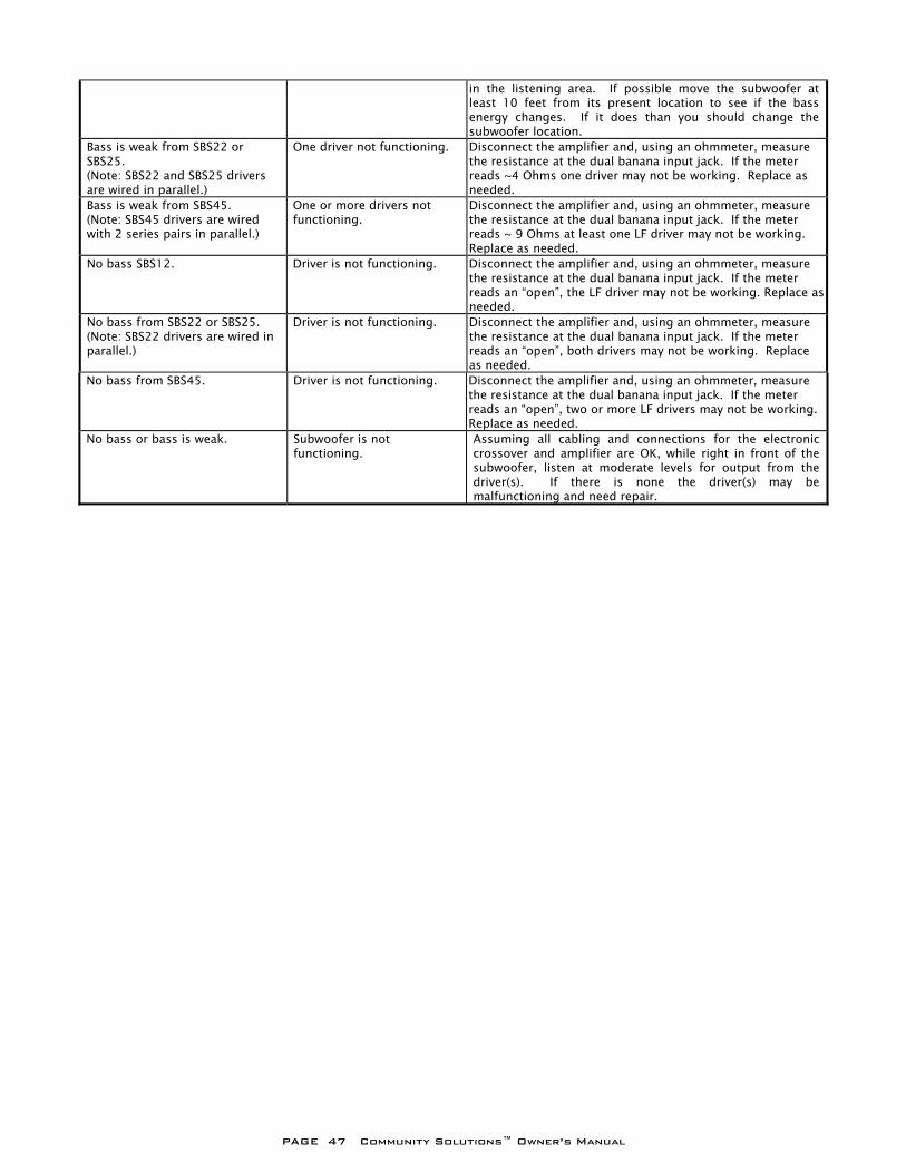
PAGE 47 Community Solutions™ Owner’s Manual
in the listening area. If possible move the subwoofer at least 10 feet from its present location to see if the bass energy changes. If it does than you should change the subwoofer location.
Bass is weak from SBS22 or SBS25. (Note: SBS22 and SBS25 drivers are wired in parallel.)
One driver not functioning. Disconnect the amplifier and, using an ohmmeter, measure the resistance at the dual banana input jack. If the meter reads ~4 Ohms one driver may not be working. Replace as needed.
Bass is weak from SBS45. (Note: SBS45 drivers are wired with 2 series pairs in parallel.)
One or more drivers not functioning.
Disconnect the amplifier and, using an ohmmeter, measure the resistance at the dual banana input jack. If the meter reads ~ 9 Ohms at least one LF driver may not be working. Replace as needed.
No bass SBS12. Driver is not functioning. Disconnect the amplifier and, using an ohmmeter, measure the resistance at the dual banana input jack. If the meter reads an “open”, the LF driver may not be working. Replace as needed.
No bass from SBS22 or SBS25. (Note: SBS22 drivers are wired in parallel.)
Driver is not functioning. Disconnect the amplifier and, using an ohmmeter, measure the resistance at the dual banana input jack. If the meter reads an “open”, both drivers may not be working. Replace as needed.
No bass from SBS45. Driver is not functioning. Disconnect the amplifier and, using an ohmmeter, measure the resistance at the dual banana input jack. If the meter reads an “open”, two or more LF drivers may not be working. Replace as needed.
No bass or bass is weak. Subwoofer is not functioning.
Assuming all cabling and connections for the electronic crossover and amplifier are OK, while right in front of the subwoofer, listen at moderate levels for output from the driver(s). If there is none the driver(s) may be malfunctioning and need repair.

PAGE 48 Community Solutions™ Owner’s Manual
18 WARRANTY INFORMATION AND SERVICE FOR THE USA Transferable Warranty (Limited) – valid in the USA only
TRANSFERABLE WARRANTY " (L IMITED)” VALID IN THE USA ONLY
Community loudspeaker systems are warranted in the USA to be free from manufacturing defects in materials and workmanship for a period of five years, as determined by one of the following two methods, whichever is longer:
Starting from the date of retail purchase, as noted on the sales receipt from an authorized Community dealer,
OR
Starting from the date of manufacture, determined by the serial number, if the sales receipt is not available.
This warranty applies to the product; therefore, the remainder of the warranty period will be automatically transferred to any subsequent owner. This warranty applies only to failure of a Community loudspeaker caused by defects in materials and workmanship during the stated warranty period. It does not apply to a unit that has been subjected to abuse, accident, modification, improper handling/installation, or repairs made without factory authorization or by anyone other than authorized Community Field Service Stations. This warranty is void if the serial number has been defaced, altered or removed. Products covered by this warranty will be repaired or replaced at the option of Community, without charge for materials or labor, provided all the terms of this warranty have been met.
OBTAINING WARRANTY SERVICE Warranty service may be obtained from the factory, or from an authorized Field Service Station. To obtain factory or field warranty service for products purchased in the United States, return the product for inspection to the address below, freight prepaid, in the original packaging. If the original packaging is not available, call or write Community Warranty Service to obtain proper packaging materials or hand carry the product to the nearest Field Service Station.
Factory Service Center: Community Warranty Service 333 East Fifth Street Chester, PA 19013-4511 USA Field Service Station: Call (610) 876-3400 for the nearest Authorized Field Service Station
For factory service, please call (610) 876-3400 for a Return Authorization (R/A) number before shipping. The following information must be included in the package:

PAGE 49 Community Solutions™ Owner’s Manual
Owner’s complete name, daytime phone number, return street address and return authorization number. The serial number of the product being returned and a copy of the retail sales receipt, if possible. A complete description of the problem(s) experienced, including a brief description of how the equipment is being used and with what brand, model and output power of amplifier.
Upon receipt, the service center will determine if the problem is covered under warranty. If covered under this warranty, the product will be repaired or replaced, at Community’s option, and returned to the owner freight prepaid. If the problem is not covered under this warranty, the owner will be notified of the problem with an estimate of the repair costs. Consequential and Incidental Damages: Community shall not be liable for any consequential or incidental damages including, without limitation, injury to persons, property, or loss of use. Some states do not allow the exclusion or limitations of consequential or incidental damages, so the above limitations and exclusions may not apply. This Community warranty is not extended by the length of time which an owner is deprived of the use of the product. Repairs and replacement parts provided under the terms of this warranty shall carry only the remaining portion of the warranty. Community reserves the right to change the design of any product from time to time, without notice and with no obligation to make corresponding changes in products previously manufactured. While this warranty gives specific legal rights, there may also be other rights that vary from state to state. No action to enforce this warranty shall be permitted ninety days after expiration of the warranty period.
WARRANTY INFORMATION AND SERVICE FOR COUNTRIES OTHER THAN THE USA
To obtain specific warranty information and available service locations for countries other than the United States of America, contact the authorized Community Distributor for your specific country or region.
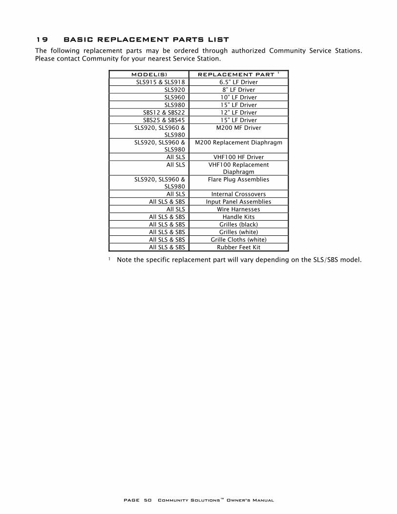
PAGE 50 Community Solutions™ Owner’s Manual
19 BASIC REPLACEMENT PARTS LIST
The following replacement parts may be ordered through authorized Community Service Stations. Please contact Community for your nearest Service Station.
MODEL(S) REPLACEMENT PART 1 SLS915 & SLS918 6.5” LF Driver
SLS920 8” LF Driver SLS960 10” LF Driver SLS980 15” LF Driver
SBS12 & SBS22 12” LF Driver SBS25 & SBS45 15” LF Driver
SLS920, SLS960 & SLS980
M200 MF Driver
SLS920, SLS960 & SLS980
M200 Replacement Diaphragm
All SLS VHF100 HF Driver All SLS VHF100 Replacement
Diaphragm SLS920, SLS960 &
SLS980Flare Plug Assemblies
All SLS Internal Crossovers All SLS & SBS Input Panel Assemblies
All SLS Wire Harnesses All SLS & SBS Handle Kits All SLS & SBS Grilles (black) All SLS & SBS Grilles (white) All SLS & SBS Grille Cloths (white) All SLS & SBS Rubber Feet Kit
1 Note the specific replacement part will vary depending on the SLS/SBS model.
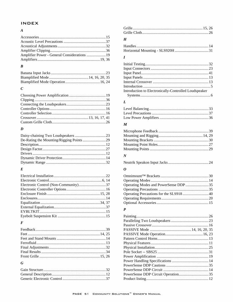
PAGE 51 Community Solutions™ Owner’s Manual
INDEX
A
Accessories ..................................................................... 15 Acoustic Level Precautions ............................................ 37 Acoustical Adjustments .................................................. 32 Amplifier Clipping.......................................................... 36 Amplifier Power - General Considerations .................... 19 Amplifiers ................................................................. 19, 36
B
Banana Input Jacks ......................................................... 23 Biamplified Mode ......................................... 14, 16, 20, 35 Biamplified Mode Operation .................................... 16, 24
C
Choosing Power Amplification ...................................... 19 Clipping .......................................................................... 36 Connecting the Loudspeakers ......................................... 23 Controller Options .......................................................... 16 Controller Selection ........................................................ 16 Crossover ...................................................... 13, 16, 17, 41 Custom Grille Cloth ........................................................ 26
D
Daisy-chaining Two Loudspeakers ................................ 23 De-Rating the Mounting/Rigging Points ........................ 29 Description...................................................................... 12 Design Factor .................................................................. 27 Drivers ............................................................................ 12 Dynamic Driver Protection ............................................. 14 Dynamic Range .............................................................. 32
E
Electrical Installation ...................................................... 22 Electronic Control ....................................................... 6, 14 Electronic Control (Non-Community) ............................ 37 Electronic Controller Options ......................................... 16 Enclosure Finish ....................................................... 15, 28 Enclosures ....................................................................... 14 Equalization .............................................................. 34, 37 External Equalization...................................................... 37 EYBLTKIT ..................................................................... 15 Eyebolt Suspension Kit .................................................. 15
F
Feedback ......................................................................... 39 Feet ........................................................................... 14, 25 Feet and Stand Mounts ................................................... 14 Ferrofluid ........................................................................ 13 Final Adjustments ........................................................... 32 Final Results ................................................................... 34 Front Grille ............................................................... 15, 26
G
Gain Structure ................................................................. 32 General Description ........................................................ 12 Generic Electronic Control ............................................. 37
Grille ......................................................................... 15, 26 Grille Cloth ..................................................................... 26
H
Handles ........................................................................... 14 Horizontal Mounting - SLS920H ................................... 31
I
Initial Testing .................................................................. 32 Input Connectors ............................................................ 23 Input Panel ...................................................................... 41 Input Panels .................................................................... 13 Internal Crossover .......................................................... 13 Introduction ...................................................................... 5 Introduction to Electronically-Controlled Loudspeaker
Systems ......................................................................... 6
L
Level Balancing .............................................................. 33 Level Precautions ........................................................... 37 Low Power Amplifiers ................................................... 36
M
Microphone Feedback .................................................... 39 Mounting and Rigging .............................................. 14, 29 Mounting Brackets ......................................................... 30 Mounting Point Holes ..................................................... 27 Mounting Points ............................................................. 29
N
Neutrik Speakon Input Jacks .......................................... 24
O
Omnimount™ Brackets .................................................. 30 Operating Modes ............................................................ 14 Operating Modes and PowerSense DDP ........................ 35 Operating Precautions .................................................... 35 Operating Precautions for the SLS918 ........................... 40 Operating Requirements ................................................. 20 Optional Accessories ...................................................... 15
P
Painting ........................................................................... 26 Paralleling Two Loudspeakers ....................................... 23 Passive Crossover ........................................................... 16 PASSIVE Mode ........................................... 14, 16, 20, 35 PASSIVE Mode Operation ....................................... 16, 23 Pattern Control Horns ..................................................... 13 Physical Features ............................................................ 11 Physical Installation ........................................................ 25 Pole Socket -- SBS25 ..................................................... 31 Power Amplification ...................................................... 19 Power Handling Specifications ...................................... 14 PowerSense DDP Cautions ............................................ 35 PowerSense DDP Circuit ............................................... 14 PowerSense DDP Circuit Operation ............................... 35 Product listing ................................................................. 12
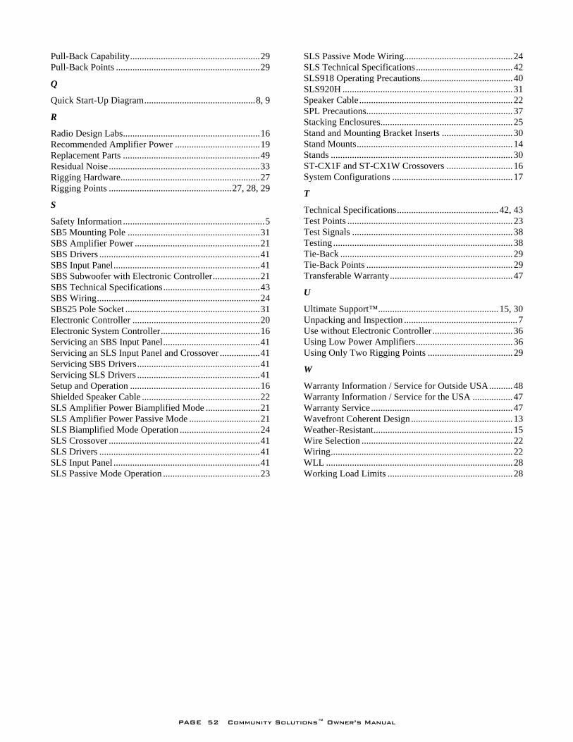
PAGE 52 Community Solutions™ Owner’s Manual
Pull-Back Capability ....................................................... 29 Pull-Back Points ............................................................. 29
Q
Quick Start-Up Diagram ............................................... 8, 9
R
Radio Design Labs .......................................................... 16 Recommended Amplifier Power .................................... 19 Replacement Parts .......................................................... 49 Residual Noise ................................................................ 33 Rigging Hardware ........................................................... 27 Rigging Points .................................................... 27, 28, 29
S
Safety Information ............................................................ 5 SB5 Mounting Pole ........................................................ 31 SBS Amplifier Power ..................................................... 21 SBS Drivers .................................................................... 41 SBS Input Panel .............................................................. 41 SBS Subwoofer with Electronic Controller .................... 21 SBS Technical Specifications ......................................... 43 SBS Wiring ..................................................................... 24 SBS25 Pole Socket ......................................................... 31 Electronic Controller ...................................................... 20 Electronic System Controller .......................................... 16 Servicing an SBS Input Panel ......................................... 41 Servicing an SLS Input Panel and Crossover ................. 41 Servicing SBS Drivers .................................................... 41 Servicing SLS Drivers .................................................... 41 Setup and Operation ....................................................... 16 Shielded Speaker Cable .................................................. 22 SLS Amplifier Power Biamplified Mode ....................... 21 SLS Amplifier Power Passive Mode .............................. 21 SLS Biamplified Mode Operation .................................. 24 SLS Crossover ................................................................ 41 SLS Drivers .................................................................... 41 SLS Input Panel .............................................................. 41 SLS Passive Mode Operation ......................................... 23
SLS Passive Mode Wiring .............................................. 24 SLS Technical Specifications ......................................... 42 SLS918 Operating Precautions ....................................... 40 SLS920H ........................................................................ 31 Speaker Cable ................................................................. 22 SPL Precautions.............................................................. 37 Stacking Enclosures ........................................................ 25 Stand and Mounting Bracket Inserts .............................. 30 Stand Mounts .................................................................. 14 Stands ............................................................................. 30 ST-CX1F and ST-CX1W Crossovers ............................ 16 System Configurations ................................................... 17
T
Technical Specifications ........................................... 42, 43 Test Points ...................................................................... 23 Test Signals .................................................................... 38 Testing ............................................................................ 38 Tie-Back ......................................................................... 29 Tie-Back Points .............................................................. 29 Transferable Warranty .................................................... 47
U
Ultimate Support™ ................................................... 15, 30 Unpacking and Inspection ................................................ 7 Use without Electronic Controller .................................. 36 Using Low Power Amplifiers ......................................... 36 Using Only Two Rigging Points .................................... 29
W
Warranty Information / Service for Outside USA .......... 48 Warranty Information / Service for the USA ................. 47 Warranty Service ............................................................ 47 Wavefront Coherent Design ........................................... 13 Weather-Resistant ........................................................... 15 Wire Selection ................................................................ 22 Wiring ............................................................................. 22 WLL ............................................................................... 28 Working Load Limits ..................................................... 28

Community Professional Loudspeakers 333 East Fifth Street
Chester, PA 19013-4511 USA TEL: 1-(610) 876-3400 FAX: 1-(610) 874-0190
www.communitypro.com
© 2010 All Rights Reserved 12JULY2010