slug memorandum - nasa · pdf fileslug memorandum for the ... angle between span axis and...
TRANSCRIPT
SEP 2510" ,r L „r RNI ilTo . ST_Ll c8
`A-TM CIN I-ED
slug
MEMORANDUMfor the
Bureau of Aeronautic,; j Nv va y Department
ITIFREE- INN-TliiFEL TESTS OF _i 1J16-SChLE `;YODEL
OF THE F..IPC;_ILD XlK-1 AIRtPL6MB
TED 17 0. NACA 2398
By
Lee T. Dau htri_dgc, Jr.
Lwngley Memorial Aeronautical L.boratoryLan ,-.-ley Field, Va.
FIl lE coTo w mo s i ami rt,
the f l"S Of thr N'It. 't111iAdvmwry t'0111mittef
1`er Atr'olsad licBwmil tun, U. a
fall now,"
TECHNICALEDI!TING
Lmmw-WAIVED
NATIONAL ADVISORY COMMITTEEFOR AERONAUTICS
WASHINGTON
SLt 3 0
puss„—^ ^^ct^►^u
https://ntrs.nasa.gov/search.jsp?R=20050031171 2018-05-12T12:18:04+00:00Z
NACA RM No. L6F,26 TItM CANCELLEDCLW^^NATIONAL ADVISORY COlWITTEE FOR AERONAU:CICS
RESEARCH MEDIORANDUIT
for the
Bureau of Aeronautics, Navy Department
FREE-SPItd?ING TUMM TESTS OF A 1 18-SCALE ?,T!ODEL
OF THE FAIRCHILD XNo-1 AIRPLATIM
TED NO. NACA 23,8
By Lee T. Da.ughtridge, Jr.
SUMMARY
Spin tests have been performed in the Langley 20-foot free-spinning tunnel. on a 1/18- 'scale model of the Fairchild XNQ••l air-plane. The s?*)in and recovery characteristics of the model weredetermined for the normal gross-weight loading and for two variationsfrom this loading - center of gravity roved rearward and relativemass distribution increased along the fuselage. These tests wereperformed for two vertical-tail plan forms. The investigation alsoincluded simulated pilot-escape tests and rudder-force tests.
The recovery characteristics of the model were satisfactory forall. conditicns tested by full reversal of the rudder and by simul-taneous neutralization of the rudder and elevator. It was indicatedthat if necessary to escape from the spinning air p lane, the pilotshould jump from the outboard side of th_- fuselage and as farrearward as possible. As determined from spin model tests, therudder pedal force required to reverse the rudder for recoveryfrom the spin-will be light.
INTRODUCTION
In accordance with a request of the Bureau of Aeronautics,Navy Department, a 118-scale model of the Fairchild XNQ-1 air-plane has been tested in the Iiingley 20-foot free-spinning tunnel.
GLASsG;r^on CANCELLED

2 MCA RAIL Mo. L6126
The XNQ-1. is a light training airplane with a two-n_lace tandemseating arrangement and conventional landing; gear.
All tests were performed with the model in the clean condition( landing gear retracted, flans neutral, and car_opy closed). Theerect spin and recovery characteristics of the model were determinedfor the normal gross-:,height loading and for two variations ofthis loadin, (1) center of gravity moved rearward of normal and(2) relative muss distribution increased along the fuselage. Eachof these loadinF conditions was investigated for different verticalt--:il plan forms (designated as on ginal and alternate, verticaltails by Fairchild). The recovery characteristics we re generallydetermined by fully reversing the rudder. Dr. 1I. Serbin, arerresentative of the Fairchild Aircraft Company, witnessed someof the shin tests, and during his visit it was decided to alsorun tosts in which rudder alone or rudder and elevator simultaneouslywere neutralized. The inverted s pin and recovery characteristicswere determir.f:d for the normal-loading condition with the originalvertical tail installed. The rudder pedal force necessary toeffect, recovery from a shin was determined and tests simulatingemergency pilot escape were also performed on they model.
SYMBOLS
b wing span, feet
S wing area, square feet
m muss of airplane, slugs
c wing chord
c mean aerodynamic chord, feet
x^-c ratio of distance of cer_ter of gravity rearward ofleading edge of mean aerodynamic chord to meanaerodynamic chord
z/c ratio of distance between center of gravity andthrust line to mean aerodynwiic chord (!positivewhen center of gravity is below thrust "Line)
I Y, IY, I Zmoments of inertia about X-, Y,and Z- body axesrespectively, slug-feet

NAGA RIA No. I6H28 3
IX - IYinertia yawinm-moment parameter
mb2
rY - IGinertia rolling-moment parameter
mb2
I ZIXinertia pitching-moment parameter
mb2
p air density, slug per cultic foot
µ relative density of airplane (m/pSb)
a angle betwe:.n thrust line and vertical (a° proximatelyequal to absolute value of an gle of attack atplane of symmetry), degrees
angle between span axis and horizontal, degrees
V full-scale true re_te• of descent, feet rer second
full-scale angular velocity about spin axis,revolutions per second
Q helix angle, angle bet.reen flight path and vertical,degrees (For this model, the average absolutevalue of the helix angle was ap proximately 7°.)
approximate angle of sideslip at center of gravity,degrees ( Sideslip is inward when inner -wing isdown by an amount greLter than the helix angle.)
APPARATUS AID METHODS
N.Tode 1
The 118-scale model of the XIdQ-1 airplane used in the spintests was furnished by the contractor and was checked for dimensionalaccuracy and rrenared for testing by Langley. The vertical positionof t1he horizontal tail was found in error and w_:s corrected by Langley.A three-view drawing and ohotorra phic views of the model with theoriginal vertical tail installed are shows, in figures 1 and 2,respectively. A drawing comparing the original and alternatevertical-tail o1ar: forms is presented as figure 3.
Z}
MICA RIM Yo. L6?m
The dimensional characteristics of the ^MQ-1 airplane arerresented in table I.
T'e l odel was ballasted to obtain dynamic similarity to theairp lane at an altitude of 10,000 feet (p = 0.001756 slug/Cu.--ft).In electromagnetic remote-con t=rol mechani sm was installed in themodel to actuate the controls fcr the recovery atte,,.*)ts and torelease the dummy pilot for the pilot-escape tests. Sufficientmoments were exerted on the controls during the recovery attemptsto reverse them fully and rapidly.
The dummy -i.lot used in the pi lot-escape tests was constructedby Langley and scaled do-iyn in both dimensions and weight to representan average ni 1_ot with a oarachute pack (200 lb) at 10,000 feetaltitude.
Wind Tunnel and 'Testing Technique
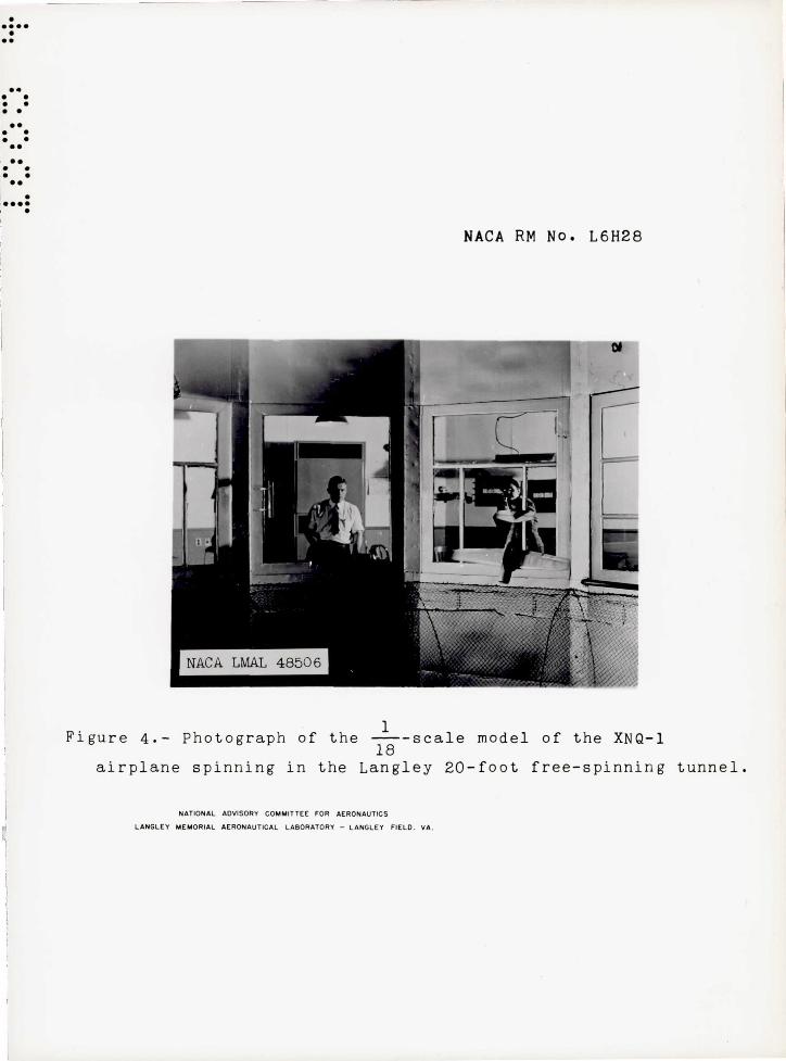
The tests were performed in the Langley 20-foot free-spinningtunnel, the operation of which is, in general, similar to thatdescribed in reference 1 for the Langley 15-foot free-spinningtunnel exce pt that the ziodel launchin g; technique has beer_ chant=ed.Vith the controls set in the desired position, the model is launchedby hand with rotation into the vertically rising air. , stream.After a number of turns in the established spin (fig. 4 shows themodel spinning in the LanFIey 20-foot free-spinning tunnel),recovery attempt is made by moving; one or more controls by meansof the remote . -control mechanism. After recovery, the model divesinto a safety net. The s p in data obtained from these tests arethen converted from model values to corres ponding full-scalevalues by methods also described in reference 1.
In. accordance with standard spin-tunnel procedure, tests were:performed to determine the s pin and recovery characteristics ofthe model t'or the r_ormai--spinning; control configuration (elevatorfull ur, ailerons neutral, and rudder full ,,!ith the spin) and forvarious otter aileron and elevator combinations includi?:^, neutraland maximtua settings of the surfaces for the various model loadingsand configurations. Recovery was ganerrzily attempted by rapidreversal of the rudder from full with to full against the spin,although, as previously mentioned, some recovery attempts weremade by neutralization of the rudder alone and by simultaneousneutralization of the rudder and elevator. Tests were alsoperformed to evaluate the possible adverse effects on recovery ofsmall deviations from the normal control configuration for spinning.For these tests, the elevator was set either at its full-up deflectionor at two-thirds of its full-up deflection and the ailerons were

NACA RDA No. L6v28
5
set one-third of the full deflection in the direction conduciveto slower recoveries. Recovery was attempted by rapidly reversingthe rudder from full with to only two-thirds against the spin.This narti.cular control configuration and manipulation is referredto herein as the "criterion spin_." Turns for recovery are measuredfrom the time the controls are moved to the time the spin rotation_ceases. The criterion for a satisfactory recovery from a srir_ fora spin-tunnel model has been ado pted as 2 turns or less, basedprimarily on the loss of altitude of the corresponding airclaneduri_n;r the recovery and subsequent dive. Recovery characteristicsof 'a model are considered satisfactory, however, if recoveryattempted from the criterion spin requires no more than :2
1 turns.
For recovery attempts in which the model struck the safetynet before recovery could be effected, the number of turns fromthe time the controls were moved to the time the model struck thesafety net was recorded. This number indicates that the modelrequired more turns to recover from the spin than shown, as,for example, > 2 1. A >2-,1--turn reoovery, however, does not
necessarily indicate an improvement when compared to a > 4-turnrecovery.
For the pilot-escape tests, the dummv pilot was alternatelyattached to the side of the fuselage at the forward seat and at therearyvard seat in order to simulate either the pilot or the studentjarring from the airplane. The duramy was released from the inboardside (the right side in a right spin) and from the outboard sideof the fuselage during a flat spin and a typical steep spin. Noflat sp ans were actually obtained during the model spin tests, buta flat spin wis simulated for the p ilot-escare tests by releasingthe durm;y while the model was still in the flat attitude causedby the rotational energy imparted to the model during launching.
in performing the rudder pedal force tests, only the forcenecessary to move the rudder so as to effect a normal recoveryfrom the spin was determined. To accomplish this, the tensionin the rubbeit band that palls the rudder against the spin wasadjusted to represent known hinge-moment values about the rudderhinge line. A series of recovery tests was then mado, the tensionin the rubber band being systematically lowered, until the turnsfor recovery began to increase. The valuE' of --"he model hingemoment rt this p oint was then converted to the correspondingfull-scale rudder pedal force at the equivalent altitude at whichthe tests were Trade.

6 l\TACA RM No. L6H28
PRECISION
The spin data pres'3n-'-'3d are belie.ed to be the true values given by the model within the following limits:
a, degr ees • • • ri. degrees • V, percent • 0, pe rcent •
.~c ••• o. . .
~Arns for r ecovery • . . • . • . . • . •
. . .. .. ,. . . . . . . o 0 • • • • • •
,-,-+ 1
I -TT" turn when obtained from , "r motion -picture record
<. +1 -- turn when obtained from 2 visual estimate
l-In some ir.ste.nce s in v!hj.ch it l':as difficult to test t hf1 !rodel due to the oscillatory or ,fandering nat'.lre of "'che spin, the forf:going; limi.ts may have be en exceeded .
Comparison between spin results of models and corr6s;::londing airnlanes (references 1 and 2) indicat'3S that s-'Jin-tunnel resuHs are not always in compJ.ete agret~ment 1I;ri tb airpJ.anc suin r esults . In general , the models spun at 9. somGwh~t smalle r angle of attack , with a elightly higher rate of deSCEnt , 3.nd \,ith 50 to 10 0 more outward sideslip the,n did thp c01'responding air?lanes . The comparison rnudc in rt3ference 2 for 20 mode Is sho-,;;s that 50 percont of the mode 1 r ecovery teets predicted satisfactorIly the number of turns rfquired fo r recove ry from thE. spin of the corresponding air"'lane and th!lt 10 percent were optimistic and 10 percent were pessimistic us regards the airpla:::J.8 r ecovery characte ristics.
Little can be stated about the precision of the pilot-e scape tests as no comparable full -scale data are available. It is considered, hov,'eve r, thr..t when the dummy pilof; is observed to clear all )'16.rts of the model by ':i. large margin after being released, tl'6 pi l ot rrs.y safely escape f rom the spinn ing airplane in an eme r gency.
Because of the imr'racticability of ballasting the model exactly and because of -inadvertent:; damage to the model during the spin te "ts , the mass distri butior. of the mode 1 varied from th-=; true scaleddown values wi thin the following limits :
Wej ght , percent . • • • • • • • • •• C6uter-o f,:gravi ty locut ion, p~rcent c . Moment s \ IX' percent . . of , Iy, percent 'inertia l I Z, percent • • • . •
. . .
4 hi ~h to 7 high . . 0 to 1 r ear-"vard
6 high to 7 high • • . • • 2 low to 1 low
2 hiEh t o 6 high

NACA RM No. L6H28 7
The measur ement of the mass char acteristics we r e made within t he following limits of accuracy:
Weight, per cent • • • . • • •••••• Center-of-gravity location, percent c • Momonts of ine r tia , percent . • •.
. . .
The controls were set with an accUT8.cy of :!: 10•
TEST CONDITIONS
. . .
Spin tests were p8rfor med for thE; cunditions of the model listed in table II . Reference 5 indicates that moving the center ·'Jf gravity r ea.r ward generally has an ad·jerse effect on the spin and recovery cha racterist ics of models with relatively low values of the relative density narameter fl . The XNQ- l model , ther e fore , vvas tested wj.th the center of graiTi ty moved rea rward in order to determine the effe ct . The modcl was tested with the r e lative mass distribution increased a long the fUSG lage to dete rmine if the effect of cont:tol di s"""osition and manirmlation on the sDin and r e covery charactcrisl;ics vonld be changed . A cording to r e f e ence h, an increa.se in. relatiyE' mo.ss distribution 0.1011g the fuselage should tend to revers e the effec t of the Qi lerons and e l evators .
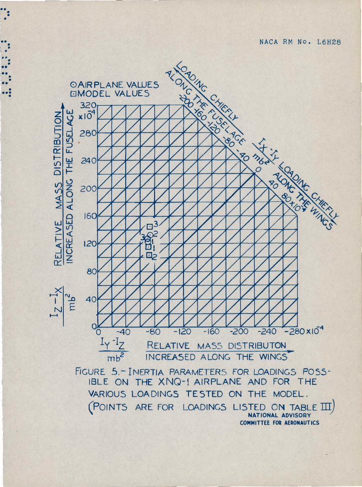
Va l ue s of the tail - damping povier factor for the original and thE; alternatE ve rtical t a i Is are g iven in table 1. The taildampint; ·,?ower factor was computed according to the method given in reference 3 . The values pre sente d were computed for the norma l gross -w~i~ht cen t e r - of-gravity location. A c ompar ison of the value s of the mass characteris tics .. and inertia pe.ra.rn.eter for the loadings tested on the mod81 , co nverted to corresponding full - scale va lues , and for various l oadings possibl e on the airplane is presented in t a ble III . The inutia yar o.mete rs are (;.lso plotted on figure 5. Thi s figure can be use d in predj cting the relative effect of contr ols on spin and recove r y char acter istics as shown in r efErence 4.
The rro.ximum control def l ecti or!s used in the te sts were as follows:
Rudde r , degrees Eleva tor, degree s . Ailerons, der.-r ee s •
. . . 30 right, :SO un , '24 up ,
30 left 20 down 12 dovm
E
IACA RM No.. L6,,iL,8
The partial control deflections used for the criterion shin
were as follows:
Rudder, 3
deflected, degrees
Elevator, deflected up , degrees . . . . . . . . . . . . . . . 20
Ad1crons, 3
deflected, degrees . . . . . . . . . . . 6 up, 4 down
When the center of gravity v.-as moved rea.rvMrd on the model, themcments of inertia were kept constant about the original center ofgravity. Y,.-hen the relative mass distribution was increased alongthe fuselage, the center of gravity was kept, at its originalposition.
RESULTS AND DISCUSSION
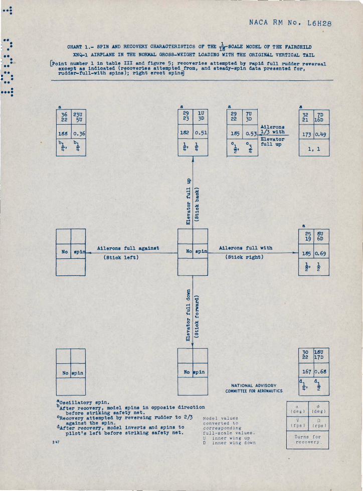
The results of the srin tests are presented in char is 1 to 5.Results for right and left spins were similar, and the resultsare e..-bi trarily presented in terms of cqui-,alent right spins.
Original Vertical Tail
Normal gross-weight loading.- The results of spin tests of the
model in the normal gross-weight loading ( point lin table III andfig. 5) with the original vortical tail. are ?,resented in chart 1.The sp ins obtained were steel (ar_gle of attack about 25 0 ) and yieregenerally oscillatory in hitch and roll. The recoveries from thesespins by full rudder reversal were very rapid, the slowest recoveryrequiring only . 1 turn. Then the elevator was up and the aileronswere ags_inst the srin, the model recovered so ra pidly that itlinmediately began to spin in the o pposite direction before strikingthe safety net. It appears, therefore, that care must be exercisedto Evoid entering; a s pin in the opposite direction when attemptinga recovery in the airplane. The model would not s pin with theelevator neutral or full down when the ailerons 1 ere neutral oragainst -the spin.
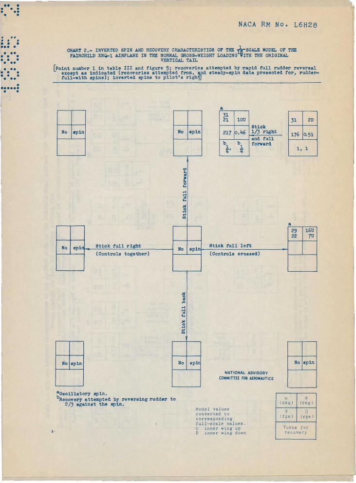
Inverted spin tests were also performed on th- model in thenormal gross-weight loading with the oriminRl vertical-tail pl,un for:tn.The results of these tests :re rresented in chart 2. The method ofp lotting the data for inverted spins is differE;nt than that forerect spins. For fully developed inverted s pins, "controls crossed"(right rudder pedal forward and stick to left for spins to pilot'sright) i s p lotted at the right of the chest, a_-^,d "stink b:. ;k" is

ISCA RM Eb. L6H28
9
plotted at the bottom of the chart.in the fully developed spin, the aiand when the controls are together,motion. The angle of wing tilt y?fto the eround.
When the controls are crossedlerons aid the rolling motion,the ailerons oppose the rollingis given as up or down relative
:Tor the inverted spin tests, the model would not snin for anycontrol configuration tested extent with the stick full forward andone-third or more to the left (right rudder redal)_and stick neutrallogitudinally and full left. Recoveries were effected very rapidlyby rudder reversal from the shins that ;sere obtained.
Variations fr om the normal gross-weight loading.- The results
of tests of the model with the center o' gravity moved 10 psrcentof the mean aerodynamLe chord rearward of normal (point 2 intable III and On 5) and fur tes;;s witli Iy and T 2 incyeased20 perceRt of ly ( point 3 in table III and 09- 5) are presentedin chart 3.
Yoving the center of gravity rearward of normal produced onlyP slight adverse effe,O on the s pin and recovery characteristics.The number of turns neoc ssai y for recovery from the normal and thecriterion s p ins incre „ed sl.ightly^ and the mcual suun with thestick neutral laterally and longitudinally where it would not spinfor this control corfiguration when the center of gravity was inthe normal position.
When the relative mass distribution: was in^reased along thefuselage, sp ins Caere obtained for all control configurations tested.The recoveries from all these s p ins, however, were still very rapid.
From the foregoing resu:' O, it arrears that the small range ofcenter-of-gravity movement rear guard of normal (approximately2 percent of the mean aerodynamic chord) and the small chances inthe relative mass distribution from the normal possible on theair p lane will not aurreciably affect the full-scale recoverycharacteristics. Inasmuch as the model sometimes went into a spinin the orposite direction immediately after recovery, it appearsthat the pilot should exercise care to avoid sueh an occurrenceon the airplane.
Alternate Vertical Tail
Normal Cr oss-weight loading.- The results of tests of the modelin the normal gross-weight leading with the alternate verical tailinstalled are presented in chart 4. The s pin characteristics and the

10 NACA RIM No. ILH28
recovery characteristics by rudder reversal were similar to thoseobtained with the original tail, the spins with the alternate tailbeing slightly stee per than those with the original tail. Accordingto the criterion of reference 3, it v.ould be exrected that theresults with the alterr..ate tail would be inferior to those u-,ith theoriginal trail, inasmuch as the tail.-damninfr. power factor is lower.'I'he rudder of tl-.e alternate tail is smaller, however, and probablyproduces less pro-spin yawing moment when with the s*y in than doesthe rudder of the original tail.. This probably accounts for thesteeper srin, and thus less anti-spin yawing moment is required ofthe rudder for recovery.
^JeutralizinpT the rudder alone was not sufficient to effectsatisfactory recoveries, but neu_-ralizing the rudder and elevatorsimultaneously produced recoveries almost r.s ra pid as those obtainedby reversing the rudder alone.
^To inverted spin tests were rerformed with the alternatevertical tail, but it is believed that the results obtained for theoriginal tail are applicable.
Variat ions from the: normal gr o ss-wei ght loading.- The resultsof tests of the model with the center of oxavity moved 10 percentof the -r!ean aerodynamic chord rearward of normal and of tests withI and I 2 increased 20 percent of Iv are presented in chart 5.
With the center of gravity moved rearward, the s pins weresteer, a-ad altho,,igh not tested, recoveries attem pted by fullr!.zdder reversal would undoubtedly have been rapid. Recoveries byrudder neutralization alone were unsatisfactory, but recoveries bysimultaneous neutralization of the rudder and elevator vvere veryrapid.
The snin characteristics P..ith the relative mass distributionincreased along the fuselage were very similar to those with thecenter of gravity moved rearward. Recovery by rudder neutralizationalone was satisfactory for tht7 norm^1-spinning configuration, butfrom results of tests in the normal loading it is felt thatunsatisfactory recoveries may be obtained if the ailerons aredeflected even slightly with the s,3in. Recoveries by simultaneousrudder smd elevator neutralization were ra pid for all aileron.deflections.
From the results of the model tests, it anpears that eitherreversing the rudder fully, being careful not to enter a spin inthe om-osite direction, or neutralizing the rudder and elevatorsimultaneously will cause the air p lane to recover satisfa^.torilyfrom developed snins.

NACA RNT P'o. L6H28
11
Landing Condition
Current Navy specifications require only 1 -turn spins to bedemonstrated in the landing condition. The XNQ-1 model, therefore,was not tested in the landing condition inasmuch as experienceindicates that an air p lane will still be in an incipient spin afteronly 1 turn and that recoveries can be effected rapidly from thisincin_i_ent s pin. Nevertheless, if a spin is entered inadvertentlyin the landing condition, :t, is recommended that the fla p s beretracted and that recovery be attempted iranediately after enteringthe spin.
Pilot-Escape Tests
Tests were made to determine from which side of the fuselageand from which cockpit, front or rear, escape should be attemptedif in ar.. uncontrollable s pin. It was observed that v,hen the dumrr_ywas released at either cockpit location from tho inboard side(right side in a right s pin) of the fuselage, it went through thenropcller disc for the steep spin and came dangerously close to thepropeller di s for the 1 , lat ; spin. '+ pen the dummy was released fromthe outboard side of the fus ,Zlage from either c-. ckpit, steep orflat s pin, it cleared L'_^e mo(.el by going over t._e tra ling edge ofthe outboard wing and under she tail. It was observed, however,than yThen released fror- the rearward cock p it, the dummy cle.,.red themodel by a larger margin. Therefore, if it becomes necessary* foreither occupant to abandon the spinning airplane, it is reconmendedthat he jump from the outboard side and as far rearward as Possible.
Rudder-Control Force
The discussion of t,e results of the sr_in tests has been basedon control effectiveness alone without regard to the forces requiredto move the controls. As previously mentioned, ho-vsver, an indicationof the control force regi.iired was determined by measuring the minimumforce necessary to move the rudder sufficiently to effect a normalrecovery in the normal 7ross-weight loading with the originalvertical tail. The for^e measured :vas. 100 pounds full scale whichis well within the ca pabilities of the pilot, and no difficultiesshould be encountered in reversing the rudder of this air p lane forrecovery from a shin.
12 NACA RM No. L6H28
CONCLUSIONS AND RECOMI{ENDATIONS
Based on the results of spin tests of 1/18-scale mode l of the XNQ-l air'T)lane in the clean condition, the following conclusions &nd recommendations are ma.de r egarding the spin and r ecovery characteri stics of the airplane with either vertical tail at an a.ltitude or 10, 000 r eet .
1. In the normal gross- weight loading, the svin s will be steel) and slight l y oscillatory . Recovery for a ll contr ol configu~ati ons will be r api d by rudde r r eversal or by neutralization of both rudd e r and e levator; changes in loading pos sible on the airplane will have no appr ec i ab l e effect on the soin and r ecover y characteristi cs.
2 . Reco'!ery from invertod s?ins wi 11 be r apid by full rudder r eV"ersa l, and r E:-covery should be followed by neutrfl.lization of the stick , 10Dfitudinally and laterally.
3. If for any reason it become s ne cessary to abandor: t he spinning airplane , it is r e commended that the p i lot jump from the outboa rd side of' the fusela!;.c and as far r ear ward as ,?oss ible .
4. The r udde r neda l f or ce neces sary to effect - spin r ec overy will be light .
Langley Memorial Aeronautical Lubora tory Nationa l Advisor y Con~ittee for Aeronautics
l.angley Fie l d , Va .
( '
T ' ~/ . T '. ,I •• f' I
: _ <. • .:. / ' ,~. ' CI {...,q../ f. , d if, (..-7 r ~ . f,
Lee T. Daughtrid ge , Jr. ' Aer onautic a l Enginee r
Aporovod : >!<.>-~:: (2 -~W"ifi· .. ,t (~ ~Q.rtley A. Soule'
Chief of Stability Resear ch Di vision
CJB
---~--
NACA RM No. L6H2-8
REFERENCES
1. Zimmerman, C. H. : Preliminary Tests in the N. A.C.A. Free Spiwing Xind Tunnel . NACA Rep. No. 557, 1936.
13
2. Seidman, Oscar, and Neihouse . A. 1.: COlllparison of PreeSpinning Wind-Tunnel Results with Corresponding Full-Scale Spin Results . !!rACA MR, Dec. 7, 1938.
3 . SeiGman, Oscar , and Neihouse , fl. . 1.: Free -Spinning IHndTunnel Tests of a Low- VI,'ing l ';onop lane with Systematic Cha.nge s i n Wings and Ta.ils . IV. - Effect of Center-of- Grflvity Lo~ation . NAC!. Rep . No. 672, 1939 .
4. Neihouse , A. 1.: A Mass-Distributj,on Criterion for Predicting the Effect of Control Mani ulation on the B.ecovery from a Spin. I-T CA l~R . hUg . 1942. -
5. NeihousG, A'1sha1 I., Lichtenstein, Jt: cob H., and Pepoon, Phi lip W.: Tail-Design Requirements for Satisfactory Spin Recovery . NAC), TN No . loi.t5 , April 1946.

NACA RM IIo . L6H28
TABLE r. - DB'lEl'fSIONAL CHARACTER 1STI 'jS OF THE FAIRCHILD
XNQ·-l AIRPLANE
Over - all l cp.gth , ft : Original ve r tical tall Alternate vertical tail
Pr opeller dixne ter, ft Propeller, no . of blades
· . .. " . . 27 . f.$ 26. 70
8 . 50 2
Wing : Spo.n , ft Area , sq ft
. .
· . . · . . . . . . . .
· . . . . . . . . .
· . " " . " . .
41.6 · . 236.00
As ect rati o • Chord, ir . :
. . . · . . . " . . · . . . . . . . . 7.4
Root · . . Mean aEll' odynamic chord • • • • • Tip (de sign) • • . . • • " ••
Taper ratio (design tin chord/root chord) Location of mean aerodynamic chord, in .
Leading ed~e of c rearward of leo.ding ed~G of root chord . • • • • • • • •
Leading edge of 0 be low centAl' line of
. .
fuse lage . • • . • • . • • Angle of incidence, dcg :
Root • • . . . . . . . " • • . · . . Fean ~8rodyno.mic chord •• Ti"'O • • • • • • • • • • • •
. . · 89 .9
. . 70 . 7 • . 47 .0
• 0 · 52
4.8
· 10 . 9
• 3 · 00 • . • 1. 21
- 1. 00 lillgle of geometric fl.ngle of sweepback Airfoil section :
dihedral (in wing ref6rence plan), deg (at leading edge of Wing) deg ••• • .
5 2.;;0
Root • • •• • • • . . . . . . . · . . . . . . NACA 2416 NACA 4409 Tip . . . . . . · . . .
Ailerons : Area (both ailar ons) , . sq· ft :
Total • • • • . • • • • • • • • Rearnard of hinge line •••••
Span (at hInge line), in . • •
. . .
· . . . . . . " . . . " . · .
10 . i-+5 · 7·97 108 . 0
Cho~d , percent of wi~g chor d (constant) · 24.5
NATIONAL ADVISORY COMMITTEE fOR AERONAUTICS
NACA R~ No . 16H28
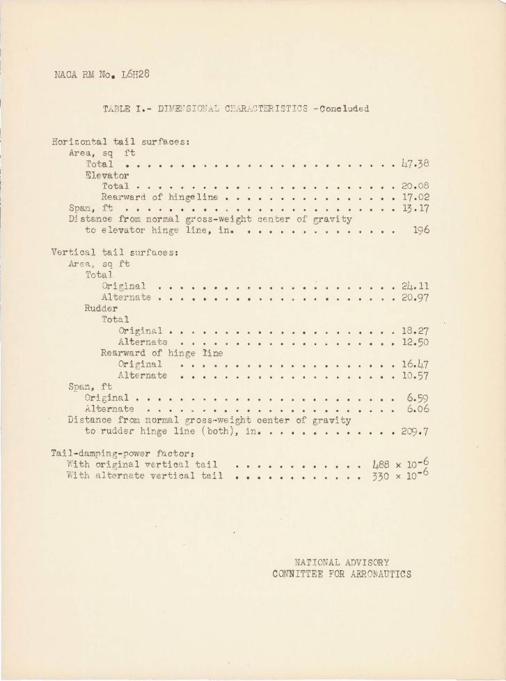
TABLE 1 . - DI .'EFSIONrlL ClL:JV-_CT:::RISTICS -Conc luded
Horizontal tai l surfe.ces: Area, sq ft
1'otal •• Eleva.tor
Total Rearward of hinge line
Sparl , ft . . . . . . . . . . . . . . . Dj stance f r om nor mal gross - weight cen I:;er of r:;ravi ty
to elevator hinge line , in . . ..... . ... .
Vertical tail surfaces : Ar G!'l. , sq ft
Total Original • • • • Alternate .
. . . . . . . Rudder
Total Origina l Alternats
Rearward of hinge line Original ••• Alterna te ••••
Spa!1., ft
. . .
Original . • • • . Alternate . .
. .
Distance from nor mal eross-weight center of gravity to rudder hinge line (both), in . . • • • • • • • •
Tail - damping- power factor : Wi th original vertical tail V;i th a1 ternate vertical tai 1 • • •
· 47 .38
· 20 . 08 · 17 ·02 · 13 . 17
196
· 24. 11 • 20 .97
18 . 27 12 . 50
· 16 . ~.7 10 ·57
6. 59 6 . 06
209 . 7
488 x 10 - 6 330 x 10- 6
NATIONAL ADVISORY COJJNITTEE FOR AERONAUTICS

NACA P~I Nc. L6H28
TABLE II. -CONDITIONS OF Th::E FAIRCHILD XNQ-l !,mDSL INVESTIGATED IN THE
FREE- SPINNI NG TUNPEL
:Clean condition (flaps neutral. landing gear retracted. canopy closed); spins to pilot's ri ghf!
,.)
Variations from the normal gross-vveight
I l oading I
Type of spin
__ ._._ . _ ______ -_____ ._. __ _ ..• __ . ___ .L _ __ . __ _
a None
None
Center of gravity move d r Gar wclrd 10 percent of c
Iy and TZ . increasod -20 per 0en~ of Iy
b ?Jone
I Cent 8r of r;r avi ty moved
i . Erect
Inverted
Ere ct
Erect
Erect
- " _ .---- - -.---- --- .- -~-,
Vertical tail !
Data on! chart !
. i i -,----------~------.--.: --- -- - -1
Origina l
Od ginal
Original
Original
Alternate
1
2
3
3
4
i
! i. I I I
i r earvrar d 1') F8rcent of C .Erect Al t E:' rna t e 5
I 1y W1d 1Z incnase d i I -20 per cent of I y l Erect . Altrne t e i 5 I '. ___ __ _ . ____ _____ __ ._ ~--- ---- ~ __ .. _---_. _ _ ._--_._-_:_ . _____ 1
aRudd6r- tension t ests wer tS 0rformed for t his cor dition .
bPilot-e scape tests wers performed for this condition.
nATIONAL ;.nVISORY CO~Th4ITT~E FOR AERONAUTICS
._-- -----~---~-~--..II
r Q^ x N CD
aNumbers correspond to numbered points on figure 5
NATIONAL ADVISORY
COMMITTEE FOR AERONAUTICS
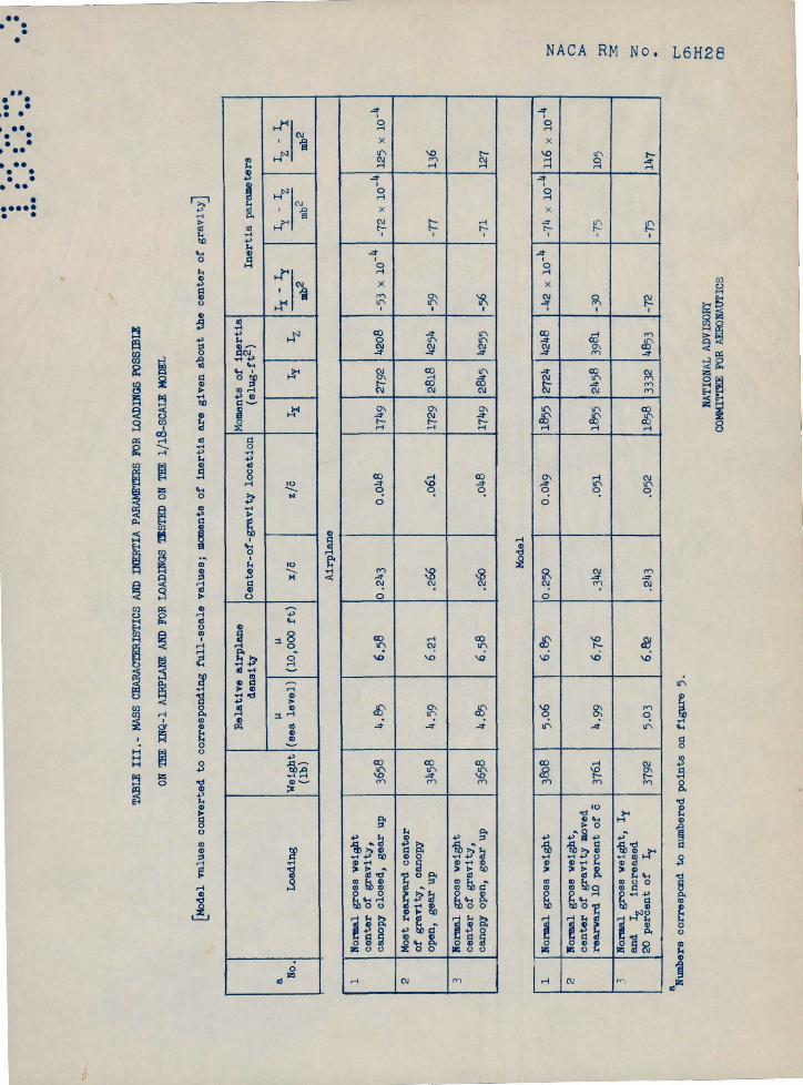
TABLE III.- MASS CHARACTERISTICS AND INERTIA PARAMETERS FOR LOADINGS POSSIBLE
ON THE XNQ-1 AIRPLANE AND FOR LOADINGS TESTED ON THE 1/18-SCALE MODEL
[Model values converted to corresponding full-scale values; moments of inertia are given about the center of gravity]
Relative airplane
Moments of inertia
density
Center-of-gravity location
(slog-ft2)
Inertia parameters
uu
IX
- IY
IY
- IZ
IZ -
IXa
No.
Loading
Weight
(sea level)
(10,000 ft)
z/c
z/c
IXIY
IZ
mb`
(lb)
mb2
mb2
Airplane
1Normal gross weight
center of gravity,
canopy closed, gear up
3658
4.55
6.58
0.243
0.048
1749
2792
4208
-53 x 10-4
- 72 x 10-4
125 x 10-4
2Most rearward center
of gravity, canopy
open, gear u
p3458
4.59
6.21
.266
Al
1729
2818
4254
-59
-77
136
3Formal gross weight
center of gravity,
canopy open,
gea
r up
3658
4.85
6.58
.260
.048
1749
2845
4255
-56
- 71
127
Model
1Formal gross weight
3805
5.06
6.85
0.250
0.049
1855
2724
4245
-42 x 10-4
-74 x 10-4
116 x 10-4
2Formal gross weight,
center of gravity moved
rearward 10
perc
ent
of c
3761
4.99
6.76
.342
.051
1855
2458
3981
-30
- 75
105
3Normal gross weight, IY
and
IZincreased
20 p
erce
nt of
IY3792
5.03
6.82
.243
.052
1858
3332
4853
-72
-75
147
z a C] a 3 z 0
NACA RM No. L6H28
•• CHART 1.- SPIN AND RECOVERY CHARACTERISTICS OF THE SCALE MODEL OF THE FAIRCHILD
•• RN(i-1 AIRPLANE IN THE NORMAL GROSS-WEIGHT LOADING WITH THE ORIGINAL VERTICAL TAIL•
••• Point number 1 in table III and figure 5; recoveries attempted by rapid full rudder reversalexcept as indicated (recoveries attempted from, and steady-spin data presented for,
' 00 0rudder-full-with spins); right erect spin•
•••
a
T25
b bl
IT,
a^9
lU
a^9 7U
23 1 3D 22 1 3D
Ailerons182 0 .51 185 0.53 1/3 with
Elevator
111 a1 0 full upIT ,f,
a 2
21 16D
173 0.x+9
1, 1
9'
H ^.-1 J4
PO WY o
p Nm ^r-1 vW
9
25 8U19 6D
NoIsp Ailerons full against Ailerons full withNo spin 185 0 69
(Stick left) (Stick right)
1 17' T
9o ^b
♦. oNo ^44^ om ^m T
W
No spin No spin
NATIONAL ADVISORY
COMMITTEE FOR AERONAUTICS
&Oscillatory spin.bAfter recovery, model spine in opposite direction
before striking safety net.cRecovery attempted by reversing rudder to 2/3 Model values
against the spin. converted todAfter recovery, model Inverts and spins to corresponding
pilot's left before striking safety net. full-scale values.U inner wing up
347 D inner wing down
30 18U22 17D
167 o.69
dl dl
ir , f
a m
Ideg) (degI
V !2
(fps) Irps)
Turns forrecovery,
• •
NACA RM No. L6H28
..••
•
CHART 2.- INVERTED SPIN AND RECOVERY CHARACTERISTICS OF THE TrSCALE MODEL OF THEFAIRCHILD XN ¢1 AIRPLANE IN THE NORN.AL GR053-WEIGHT LOADING 7WITH THE ORIGINAL
VERTICAL TAIL
Point number 1 in table III and figure 5; recoveries attempted by rapid full rudder reversalexcept as indicated (recoveries attempted from, and steady-spin data presented for, rudder-full-with spins); inverted spine to pilot's right]
a
3121 100 jl 2D
stickNo spin No spin 217 0.46 1/3 right 176 0.51
and full
b
forward97,
^1, 1
b
00
00.aY
d
29 1cU22 7U
No spi stick full right No spinStick full left
(Controls together) (Controls crossed)
A40mA.i
AdU
a-+tD
No spin No spinNo spin
NATIONAL ADVISOPY
COMMITTEE FOR AERONAUTICS
a0sclllatory spin.bRecovery attempted by reversing rudder to
2/3 against the spin. (deg] (deg)Model values V Zconverted to
correspondingfps] (rpsl
full-scale values.U inner wing up Turns for
3 ' D inner wing down recovery

,
• •
• ••
• ••
. .
. ..
••
••
CHAR
T 3
.-SP
IN A
ND R
ECOV
ERY
CHA
RAO
TERI
STIO
S or
T~ ~SCALE K
OD
EL o
r TH
E FA
IRO
HIL
D XN~l A
IRPL
AN
E W
ITH
V
ARI
ATI
ON
S FR
OM T
HE
NO
RMA
L LO
AD
ING
AND
W
ITH
THE
OR
IGIN
AL
VER
TICA
L TA
IL
[Loa
dlng
as
lnd
icat
ed;
reco
ver
les
atte
mp
ted
by
rap
ld f
ull
ru
dd
er r
ev
ers
al
exce
pt
al
lnd
1ea
ted
(re
cov
erle
l at
teap
ted
tro
m,
an
d
Ite&
4y
.pln
dat
a p
rele
nte
d t
or,
ru
dder-
full
-wlt
h s
pln
l);
rlg
ht
ere
ct
epln
ij
Oen
ter
ot
gra
vlt
y m
oved
10
per
cen
t o
t ~ re
arw
ard
of
norm
al
(po
lnt
num
ber
2 ln
tab
le I
II a
nd f
lgu
re 5
) Iy
and
IZ
ln
crea
sed
20
per
cen
t o
f Iy
(p
oin
t nu
mbe
r 3
1n
ta
ble
III
and
flg
ure
5)
ab
ab
ab
211
lag
33
36
~D
11
21
1 50
11
1 ~2
0
176
0.3
2 16
7 p.~l
173 p
.~2
c l 01
1 ~
d i, d
11."'
11."
~,
1
~p,
+>
;3
.14~
II
'" ~ ...
0.1
4
0I.
cl
., ...
"'0
c+
> ~§
' ..
. ;3
+>
11
e~
iii'"
co,o
II
b ..
~ ...
...
r<\
.....
... ,
...
;3
31
20U
~
... iii'"
17
5u
A1l
eron
e A
ller
ons
No
!spl
n
full
ag
alnst
1111
1 0
.511
full
wlt
h
(Stl
ck
left)
(S
tick
rlg
ht)
1
1 11
."' 11."
J.o
0 .14
~
+>
II
0l."
d ~ .
.. C
:!
o~
~:a
co
"'.
bl"''
'' ~
No
spln
No
sp
ln
--
ab 39
60
29
1~0
161
0.3~
it, 1
22
10
179
0.70
1 1
It'
~
b
27
l~U
20
1~0
173
0.7~
sl
e l Jr
' tr
ab 30
3U
161
0.3€
c 1
c
4'
t l
ero
ns
13 a
gai
nst
A
i 1 E
2 le
vat
or
13 u
p 35
19U
27
IO
U
152
0.5
3
c 1 c l
Jr'
It
36
9U
1311
0.5~
1 1
~'
~
aWan
derl
ng
spln
. 9
)scl
11a
tory
sp
ln.
~After
reo
ov
ery
, mo
del
sp
lns
ln o
pp
osl
te d
lrectl
on
bef
ore
st
rlk
ing
safe
ty n
et.
-~ecovery
atte
mp
ted
by
rev
ersl
ng
ru
dder
to 2
/3 a
gal
nst
th
e sp
ln.
e Aft
er r
ecov
ery
, m
odel
lnv
ert
s an
d sp
ins
to p
l10
t's
left
bef
ore st
rlk
ing
safe
ty n
et.
ab
ab
ab
29
ID
311
3D
~
21D
b
23
liD
21
10D
26
60
37
2U
211
30
170 O.~
1M
17
9 0
.~2
1 1
~,
d it 16~
0.4-1
1 11
."' ~
I,
1
~, ~
..cl
c ..
~p,
0'"
+>
;3
ab
"'_
II
.. ~ ...
...
r<\
.....
31
... , ~e
2U
~ ...
26
7U
22
1D
161
0.59
19
0 0·
70
1 1
i, 1
It'
~
11."
b b
33
13U
29
27
6u
21
7U
14-!!
0.
59
167
0.6
9
1 1
e 1 e 1
If"'
~
~,
~
NA
TIO
NA
L A
DV
ISO
RY
C
OM
MIT
TEE
FOIl
AER
ON
AUTI
CS
<l
<I>
(de
g I
(d
eg
) M
od
el
valu
es
con
ver
t.ed
1.
0 V
n
co
rre
spo
nd
ing
(fp
s)
(r
ps)
full
-sca
le
va
lue
s.
U
inn
er
win
g
up
Tu
rns
fo
r D
in
ne
r w
ing
dow
n re
cov
er
y
z >
()
> ::a
3:
Z o l'
()) ::z::
C\)
(X
l
.---
.••

-+ as a
m t+a oO YN mO >-4 ma w
ab
29 9D22 16D
199 o.6
f f
7 1d
11T, 11T
ab
NACA RM No. L6H28
••• •
. 0 CHART 4.- SPIN AND RECOVERY CHARACTER13TICS OF THE 1 SCALE MODEL OF THE FAIRCHILD XNQrl•• AIRPLANE IN THE NORMAL GROSS-WEIGHT L ADING WITH THE ALTERNATE
0 VERTICAL TAIL
Point number 1 in table III and figure 5; recoveries attempted by rapid full rudder reversal
0000 except as indicated (recoveriesattempted from, and steady-spin data presented for, rudder-
• • full-with spins); right erect spin•
••••
ab
29 12U21 0
No spin 205 0.47
1 32^ r1
c l o7 , > 2
d d1 1ir' ir
S.^ y Ma ox> .i Um rl Y m.-1 ^ Ul AW
Ailerons full against
(Stick left)No L.
b
1613U
f+U
Ailerons full with220 0.69
(Stick right)
1 1
T , Ir
90o --
b
^ moa.
000Cd yemsW --^
NATIONAL ADVISORYCOMMITTEE FOR AERONAUTICS
AWandering spin.b0scillatory spin. a mcRecovery attempted by neutralizing the rudder. (deg) (deg)dRecovery attempted by simultaneously neutrallzlng.odel values
the rudder and elevator. Vconverted to
cRecovery attempted by reversing the rudder to correspondingfps) lrpsI
2/3 against the spin. full-scale values.(Model goes into spiral dive after recovery. U inner wing up Turns for
347 D inner wing down recovery

(deg)
(deg
)
V n
ffpsI
lrpsl
Turns for
recovery
z a a z O r (V
:. . •00 '0.'
'.:
CHART 5.- SPIN AND RECOVERY CHARACTERISTICS OF THE rr SCALE MODEL OF THE FAIRCHILD XN4-1 AIRPLANE WITH VARIATIONS FROM
THE NORIAL LOADING AND WITH THE ALTERNATE VERTICAL TAIL
Loading as indicated; recoveries attempted as Indicated (recoveries attempted from, and steady-spin data presented for, rudder-full-
with spins); right erect spins)
q
Center of gravity moved 10 percent of o rearward of normal
(point number 2 in table III and figure 5)
ad
a
24 3U
34 2D
^7 3D
21 26D
No s
pin
202 0
.37
176 o
.43
b0
IC'
If
> 2
ir
b
o0
>
Elevator full up
4(stick back
Ailerons
Ailerons
full against
full with
(Stick left)
(Stick right
Iy and IZ Increased 20 percent of Iy (point number 3 in
table III and figure 5)
a
18 lU
21
7 a
41
bb
11
2'
I oI
C'
cIC
No spin
ad
D22 24D
192 D.4
a
>3
0
0
ti o
e
OS
O d
o r
l 1 V
r ^
O (
O O
W b
-^M
aOscillatory spin.
bRecovery attempted by neutralizing the rudder.
°Recovery attempted by simultaneously neutralizing the rudder and elevator.
"Wandering spin.
NATIONAL ADVISORY
COMMITTEE FOR
AERO
NAUT
ICS
Model values
converted to
corresponding
full-scale values.
U inner wing up
D inner wing down

NACA RM No. L6H28
Elevator hingeline
Aileron hingeline ^
6.00I/
2.6 1
18.45
4.73 11.655^^
2.07
Fus. ref. line .19 .89 ¢,40
``Rudderhinge line
Figure 1. - Three-view drawing of the & -scalemodel of the Fairchild XNQ-1 airplane withthe original vertical tail as tested in the
^. free -spinning tunnel. Center of gravity isshown for the normal gross--weight loading.
NATIONAL ADVISORYCOMMITTEE FOR AERONAUTICS

••
NACA RM No. L6H28
Figure 2.- Photographic views of the 18
-scale model of the XNQ-1
airplane with the original vertical tail installed.
NATIONAL ADVISORY COMMITTEE FOR AERONAUTICS
LANGLEY MEMORIAL AERONAUTICAL LA80RATORY - LANGLEY FIELD. VA .

O RIGINAL TAl L ALTERNATE TAil - - -
1-. 51. 84" "I
" I /
/ /
/ \
\ \ \ \ \ \ \ I
37.25"
· -.. ----,---.-.~- ... --- . • • •••• • • • •• ••• •• ••• •• •••• ••
79,20
72.72 II
NATIONAL ADVISORY COMMITTEE FOIl AERONAUTICS
"
z > o > ::0 3:
z o
F IGURE J. - A COMPARJ SON DRAWING Of THE ORIGINAL AN 0 ALTERNATE VERTICAL TAI L PLANFORM5 TESTED ON THE I ~ - SCALE MODEL Of THE XNQ-i AI RPLANE ( DIMENSIONS SHOWN ARE FULL -SCALE)
r (J)
::r: (\)
en
NACA RM No. L6H28
Figure 4.- Photograph of the 18
-scale model of the XNQ-1
airplane spinning in the Langley 20-foot free-spinning tunnel.
NATIONAL ADVISORY COMMITTEE FOR AERONAUTICS
LANGLEY MEMORIAL AERONAUTICAL LABORATORY - LANGLEY FIELD. VA .
O
Of
v7
D
II•••
OAIR PLANE VALUESEIMODEL VALUES
320LLJ
X154
WD^LL-
280. /ZZ
= 240H
Z 200JQ0v7
160O3
< ^q2^Z
1204 iq2
5Ld
QJWry
NACA RM No. L6H28
^o
'^c c
so Ls^^^^o Cy
`Fo ^6O
CS
XN E
40
0 -40 -80 -120 -160 -200 -240 -280 x 104
IY -IZ RELATIVE MASS DI-TRIBUTON
rTtb2 INCREASED ALONG THE WINGSFIGURE S.- INERTIA PARAMETERS FOR LOADINGS P055-
ISLE ON THE XNQ- t AIRPLANE AND FOR THEVARIOUS LOADINGS TESTED ON THE MODEL.(POINTS ARE FOR LOADINGS LISTED ON TABLE TH)
NATIONAL ADVISORYCOMMITTEE FOR AERONAUTICS