sm 800.40 flexairvalve
TRANSCRIPT

FLEXAIR® PNEUMATIC CONTROL VALVES
Service Information
SM-800.40
Table of Contents Page Technical Data 1 Operation 2 Maintenance and Repair 2 Disassembly 3 Levers 3 Model Designation Code 4 Assembly View 5 Assembly (Exploded) 6 Parts List 7 Body Assemblies 8-9 Graduating Vlvs-Seat Replacement 8 Graduating Spring Assemblies 10 Adjustment 11 Obsolete Assemblies 12 Design Changes Affecting Replacement 12 Accessories 13 Test Arrangement Diagram 14 Testing and Test Set-Up 15 Repair and Conversion Kits 16 Part Number Index 17
Port sizes 1/4"-18 NPTF Working pressure per control valve spring rating
Supply pressure max. 150 psi (10.3 bar) Temperature range -40°F to +160°F (-40°C to +71°C)
Media Air, clean and dry Materials Housing and Body: Die cast aluminum
Internal Parts: Rubber (Buna-N), aluminum,
Weight 6 lbs. (2.7 kg)
Technical Data
stainless steel
INTRODUCTION
The FLEXAIR Valve is a highly versatile pressure control valve with many assembly combinations for a wide variety of control functions. There are three valve cavities in the body which may contain several types of valve assemblies or may be plugged. Two standard handle lengths, plus an adjustable handle, are available. Various handle guide inserts limit the handle motion to the desired areas of travel. The handle return characteristic may be one of three different types.
Since its introduction, the Flexair Valve has undergone a number of design changes and modifications to improve performance and satisfy customers’ requests. The engineering performance and production quality of the current valve are the result of years of field service.
This publication points out most of the design changes that affect interchangeability of parts and, thus, assist you in updating your valve. Major repair kits, which include necessary conversion kits if applicable, are listed in the “Part Number Index” on the last pages of this publication. When these kits are installed as recommended, the result should be a fully rebuilt, current Flexair Valve. Partial repair kits are listed by model designation under “Repair & Conversion Kits.”
Page 2
Installation and General Maintenance Recommendations
WARNING! The user of these devices must conform to all applicable electrical, mechanical, piping and other codes in the installation, operation or repair of these devices. INSTALLATION! Do not attempt to install, operate or repair these devices without proper training in the technique of working on pneumatic or hydraulic systems and devices, unless under trained supervision. Compressed air and hydraulic systems contain high levels of stored energy. Do not attempt to connect, disconnect or repair these products when a system is under pressure. Always exhaust or drain the pressure from a system before performing any service work. Failure to do so can result in serious personal injury. MOUNTING! Devices should be mounted and positioned in such a manner that they cannot be accidentally operated.
WARNING: INSTALLATION AND MOUNTING
Maintenance
Major repair kits, which include necessary conversion kits, are
listed in the “Part Number Index” (page 17). For partial repair kits by model designation, see “Repair & Conversion Kits” on page 16.
NOTE: Every 500 hours of operation, clean and lubricate the following portions of the valve (it is not necessary to remove the valve from its mounting): slots inside the latch cover (9); slots, center hole, underside and groove on the detent latch (108); edges of the handle guide insert and the four detent lugs on the cover (14). Lubricate with Sun Oil Company C-8-91-1, Sunaplex 780, Texaco Marfax-0 or equivalent grease.
Every 1000 hours of operation, using the above lubricant, additionally clean and lubricate the following (it is not necessary to remove the valve from its mounting): contact ends of the set screws (27); handle shafts (29); contact surface (top) of the full pressure adjusting caps (33); and the inside of the handle shaft bearing (24). Refer to the “Assembly View” on page 5 for other lubrication points.
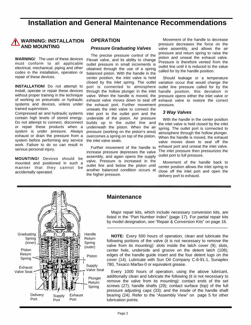
OPERATION Pressure Graduating Valves The precise pressure control of the
Flexair valve, and its ability to change outlet pressure in small increments is obtained through the use of a spring balanced piston. With the handle in the center position, the inlet valve is held closed by the inlet spring. The outlet port is connected to atmosphere through the hollow plunger in the inlet valve. When the handle is moved, the exhaust valve moves down to seal off the exhaust port. Further movement unseats the inlet valve to connect the inlet port to the outlet port and the underside of the piston. Air pressure builds up in the outlet line and underneath the piston. When the air pressure (working on the piston’s area) overcomes a spring on top of the piston, the inlet valve seats.
Further movement of the handle to increase pressure depresses the valve assembly, and again opens the supply valve. Pressure is increased in the outlet line and below the piston until another balanced condition occurs at the higher pressure.
Movement of the handle to decrease pressure decreases the force on the valve assembly, and allows the air pressure and return spring to raise the piston and unseat the exhaust valve. Pressure is therefore vented from the outlet line until it is reduced to the value called for by the handle position.
Should leakage or a temperature variation occur that would change the outlet line pressure called for by the handle position, this deviation in pressure opens either the inlet valve or exhaust valve to restore the correct pressure.
3 Way Valves With the handle in the center position
the inlet valve is held closed by the inlet spring. The outlet port is connected to atmosphere through the hollow plunger. When the handle is moved, the exhaust valve moves down to seal off the exhaust port and unseat the inlet valve. The inlet pressure then pressurizes the outlet port to full pressure.
Movement of the handle back to center position allows the inlet spring to close off the inlet port and open the delivery port to exhaust.
Handle Return Spring (outer)
Piston
Supply Valve Seat
Plunger Return Spring
Exhaust Port
Supply Port
Delivery Port
Exhaust Valve Seat
Piston Return Spring
Graduating Spring (inner)
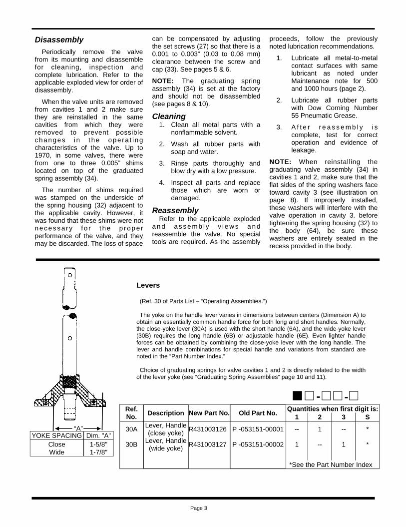
Ref. No. Description Old Part No. Quantities when first digit is:
1 2 3 S
30A Lever, Handle (close yoke) P -053151-00001 -- 1 -- *
30B Lever, Handle (wide yoke) P -053151-00002 1 -- 1 *
*See the Part Number Index
New Part No.
R431003126
R431003127
YOKE SPACING Dim. "A" Close 1-5/8" Wide 1-7/8"
Disassembly Periodically remove the valve
from its mounting and disassemble for cleaning, inspection and complete lubrication. Refer to the applicable exploded view for order of disassembly.
When the valve units are removed from cavities 1 and 2 make sure they are reinstalled in the same cavities from which they were removed to prevent possible changes i n t he ope ra t i ng characteristics of the valve. Up to 1970, in some valves, there were from one to three 0.005” shims located on top of the graduated spring assembly (34).
The number of shims required was stamped on the underside of the spring housing (32) adjacent to the applicable cavity. However, it was found that these shims were not necessa ry f o r t he p rope r performance of the valve, and they may be discarded. The loss of space
can be compensated by adjusting the set screws (27) so that there is a 0.001 to 0.003” (0.03 to 0.08 mm) clearance between the screw and cap (33). See pages 5 & 6.
NOTE: The graduating spring assembly (34) is set at the factory and should not be disassembled (see pages 8 & 10).
Cleaning 1. Clean all metal parts with a
nonflammable solvent.
2. Wash all rubber parts with soap and water.
3. Rinse parts thoroughly and blow dry with a low pressure.
4. Inspect all parts and replace those which are worn or damaged.
Reassembly Refer to the applicable exploded
a n d a s s e m b l y v i e w s a n d reassemble the valve. No special tools are required. As the assembly
proceeds, follow the previously noted lubrication recommendations.
1. Lubricate all metal-to-metal contact surfaces with same lubricant as noted under Maintenance note for 500 and 1000 hours (page 2).
2. Lubricate all rubber parts with Dow Corning Number 55 Pneumatic Grease.
3. A f t e r r e a s s e m b l y i s complete, test for correct operation and evidence of leakage.
NOTE: When reinstalling the graduating valve assembly (34) in cavities 1 and 2, make sure that the flat sides of the spring washers face toward cavity 3 (see illustration on page 8). If improperly installed, these washers will interfere with the valve operation in cavity 3. before tightening the spring housing (32) to the body (64), be sure these washers are entirely seated in the recess provided in the body.
Levers (Ref. 30 of Parts List – “Operating Assemblies.”) The yoke on the handle lever varies in dimensions between centers (Dimension A) to obtain an essentially common handle force for both long and short handles. Normally, the close-yoke lever (30A) is used with the short handle (6A), and the wide-yoke lever (30B) requires the long handle (6B) or adjustable handle (6E). Even lighter handle forces can be obtained by combining the close-yoke lever with the long handle. The lever and handle combinations for special handle and variations from standard are noted in the “Part Number Index.” Choice of graduating springs for valve cavities 1 and 2 is directly related to the width of the lever yoke (see “Graduating Spring Assemblies” page 10 and 11).
“A”
Page 3

MODEL DESIGNATION CODE
INSERT VALVE CAVITY ACTUATED OLD D & S OLD F
A 1, 2 separately P -053153-00003 P -054173-00003 B 2, 3 sep or simult P -053153-00002 P -054173-00002 C 2 only P -053153-00004 P -054173-00004 D 1, 2, 3 sep; 1, 3 or 2, 3 simult P -053153-00000 P -054173-00000 E 1, 3 sep or simult; 2 after 3 P -053153-00001 P -054173-00001 G 1, 2, 3 sep P -053153-00005 P -054173-00005 J 1, 2, 3 sep; 1, 3 simult P -053153-00006 P -054173-00006 K 1, 3 sep; 2 after 3 P -053153-00010 P -054173-00010 L 2, 3 sep P -053153-00026 P -054173-00016 M 3 sep; 2 after 3 P -053153-00012 P -054173-00012* N 1, 3 sep or simult P -053153-00013 P -054173-00013 P 3 sep; 1 partial; 1 full after 3 P -055477-00001* —- R (no longer used) N/A N/A U (no longer used) N/A N/A
HANDLE GUIDE INSERTS NEW D & S R431003131 R431003130 R431003132 R431003128 R431003129 R431003133 R431003134 R431003135
—- R431003136 R431003137 R431003746
NEW F R431003320 R431003319 R431003321 R431003318
—- R431003322
—- R431003323
—- —- —- —-
Part No. According to 4th digit:
COVER WITH INSERTS
DESIGNATION CODE EXAMPLE 1 A -A D -0 SIDE
VALVE
HANDLE
RETURN
VALVE D-Spring return with detents
CAVITIES F-Friction (short handle only)
1 & 2 S-Spring return, no detents
HANDLE A-One operating valve, other
GUIDE cavity plugged
INSERTS B-Two operating valves
HANDLE (see diagrams)
LENGTH
1-Long Handle
2-Short Handle
3-Adjustable Handle
Inserts are staked in place and require replacement of the complete cover when changing the function of the valve.
0-Cavity plugged 1-3 way valve 2-Graduating
A
3
2
1
3
2
1
3
2
1
3
2
1
3
2
1
3
2
1
3
2
1
3
2
1
3
2
1
3
2
1
3
2
1
3
2
1
3
2
1
3
2
1
B C D E G
J K L M N P R U
* No detent lugs on cover.
Page 4

ASSEMBLY VIEW
Contact surfaces of valve cavity details that require lubrication when valve is periodically disassembled for cleaning, inspection and lubrication. See page 3, Reassembly Note 1.
Page 5

EXPLODED VIEW
Handle Assemblies (See “Levers” for handle and lever relationship-page 3.) (Refer to Parts List) HANDLE ASSEMBLIES
WHEN 1ST DIGIT IS 1 2 3 S
OPERATING ASSEMBLIES WHEN 4TH DIGIT IS D S F
D S
F
For Handle Guide Insert, see page 4.
See “Obsolete Assemblies”
See page 3 (Levers)
7
8
9
7
8
9
10A
10B 10C
10A
10B
14
13 12
14
13 12
31
31
27
26 25
27
26 25
30
30
11A - 11B
11A
28 29A
24 23
24 23
28 29B
32A 32B
32C
22
21 17
20 19
18 15 16
Page 6
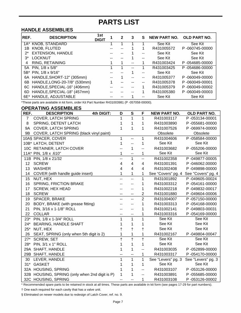
PARTS LIST HANDLE ASSEMBLIES
REF. DESCRIPTION 1st DIGIT 1 2 3 S NEW PART NO. OLD PART NO.
1A* KNOB, STANDARD 1 1 1 1 See Kit See Kit 1B KNOB, FLUTED -- -- 1 1 R431005572 P -060745-00000 2* EXTENSION, HANDLE -- -- 1 -- See Kit See Kit 3* LOCKNUT -- -- 1 -- See Kit See Kit 4 RING, RETAINING 1 1 -- 1 R431003424 P -054685-00000
5A PIN, 1/8 x 5/8" 1 1 -- 1 R431003425 P -054686-00000 5B* PIN, 1/8 x 9/16" -- -- 1 -- See Kit See Kit 6A HANDLE,SHORT-12" (305mm) -- 1 -- -- R431005377 P -060049-00000 6B HANDLE,LONG-20-7/8" (530mm) 1 -- -- -- R431005378 P -060049-00001 6C HANDLE,SPECIAL-16" (406mm) -- -- -- 1 R431005379 P -060049-00002 6D HANDLE,SPECIAL-18" (457mm) -- -- -- 1 R431005380 P -060049-00003 6E* HANDLE, ADJUSTABLE -- -- 1 -- See Kit See Kit
*These parts are available in kit form, order Kit Part Number R431003981 (P -057058-00000).
OPERATING ASSEMBLIES REF. DESCRIPTION 4th DIGIT: D S F NEW PART NO. OLD PART NO.
7 COVER, LATCH SPRING 1 1 1 R431003117 P -053134-00001 8 SPRING, DETENT LATCH 1 1 1 R431003890 P -055681-00000
9A COVER, LATCH SPRING 1 1 1 R431007526 P -069974-00000 9B COVER, LATCH SPRING (black vinyl paint) Obsolete Obsolete
10A§ SPACER, COVER 1 -- 1 R431004606 P -058584-00000 10B* LATCH, DETENT 1 -- 1 See Kit See Kit 10C RETAINER, LATCH COVER -- 1 -- R431003682 P -055206-00000 11A* PIN, 1/8 x .610" 1 -- 1 See Kit See Kit 11B PIN, 1/8 x 21/32 -- 1 -- R431002358 P -049877-00005 12 SCREW 4 4 4 R431001391 P -046062.00000 13 WASHER 4 4 4 R431002408 P -049898-00000 14 COVER (with handle guide insert) 1 1 1 See “Covers” pg. 4 See "Covers" pg. 4 15 NUT, HEX -- -- 1 R431001892 P -049605-00024 16 SPRING, FRICTION BRAKE -- -- 1 R431003312 P -054161-00000 17 SCREW, HEX HEAD -- -- 1 R431002218 P -049832-00017 18 SCREW -- -- 2 R431001880 P -049604-00006 19 SPACER, BRAKE -- -- 2 R431004007 P -057150-00000 20 BODY, BRAKE (with grease fitting) -- -- 1 R431003313 P -054168-00000 21 PIN, 3/16 x 1-1/8" ROLL -- -- 1 R431002141 P -049803-00031 22 COLLAR -- -- 1 R431003316 P -054169-00000 23* PIN, 1/8 x 1-3/4" ROLL 1 1 1 See Kit See Kit 24* BEARING, HANDLE SHAFT 1 1 1 See Kit See Kit 25* NUT, HEX † † † See Kit See Kit 26 SEAT, SPRING (only when 5th digit is 2) 1 1 1 R431002167 P -049804-00047 27* SCREW, SET † † † See Kit See Kit 28* PIN, 3/1 x 1" ROLL 1 1 1 See Kit See Kit 29A SHAFT, HANDLE 1 1 -- R431003035 P -052899-00000 29B SHAFT, HANDLE -- -- 1 R431003317 P -054170-00000 30 LEVER, HANDLE 1 1 1 See “Levers” pg. 3 See "Levers" pg. 3 31* GASKET 1 1 1 See Kit See Kit 32A HOUSING, SPRING 1 1 -- R431003107 P -053126-00000 32B HOUSING, SPRING (only when 2nd digit is P) 1 1 -- R431003891 P -055685-00000 32C HOUSING, SPRING -- -- 1 R431003108 P -053126-00002
* Recommended spare parts to be retained in stock at all times. These parts are available in kit form (see pages 17-29 for part numbers). † One each required for each cavity that has a valve unit. § Eliminated on newer models due to redesign of Latch Cover, ref. no. 9.
Page 7

BODY ASSEMBLIES NOTE: See the "Part Number Index" for exact assembly. When only one graduating valve is required and cavity 3 is plugged, normal assembly is with the graduating valve in cavity 2. Push or pull operation can be obtained by proper mounting of the Flexair® Valve.
QTY REF. NO. DESCRIPTION I II III OLD PART NO.
33* CAP, Full pressure adjusting - 1 2 See Kit
34 ASSEMBLY, Graduating spring - 1 2 †
34A* O-RING - 1 2 See Kit
34B† SEAT, Exhaust valve (not shown) - 1 2 P -005137-00000
34C† CLIP - 1 2 P -059672-00000
35* SPRING, Piston return - 1 2 See Kit
36 SPACER, Filter 1 2 4 P -058471-00000 37 RING, Retaining 1 1 2 P -049882-00005 38 PLUG 1 - - P -053135-00001
39* Seat, Supply valve - 1 2 See Kit 40* O-RING 1 1 2 See Kit 41† PLUNGER, Valve - 1 2 P -066554-00000 42* O-RING 1 1 2 See Kit
43* SPRING, Plunger return - 1 2 See Kit
44 WASHER - 1 2 P -049804-00017 45* O-RING - 1 2 See Kit
I Plugged cavity II Graduating Valve III Two Graduating * Recommended spare parts to be retained in stock at all times.
These parts are available in kit form (see "Repair & Conversion Kits” page 16).
† See "Graduating Spring Assemblies" page 10.
NEW PART
NO.
See Kit
†
See Kit
R431000512
R431005207
See Kit
R431004545 R431002385 R431003118
See Kit See Kit
R431006833 See Kit
See Kit
R431002158 See Kit
Graduating Valves Cavities 1 & 2 SUPPLY VALVE SEAT REPLACEMENT Before removing or installing the retaining ring (37), force the plunger (41) down until the plunger is exposed below the bottom of the valve body (65).
REF. NO. DESCRIPTION QTY OLD P/N
63 SCREW 3 P -049832-00008 64 WASHER, LOCK 3 P -049982-00006 65 BODY 1 P -052884-00003
NEW P/N
R431002216 R431002572 R431003029
CAVITIES 1 & 2 WHEN 3RD DIGIT IS…
Cavity 2
Cavity 1
Cavity 3
A B One Graduating Valve One Plugged Cavity Two Graduating Valve
PLUGGED CAVITY GRADUATING
VALVE GRADUATING
VALVE
CAVITIES 1 & 2
Page 8

BODY ASSEMBLIES Cavity 3
REF. NO. DESCRIPTION 0 1 2 OLD P/N
46 SEAL, DUST 1 - - P -005163-00000
47* SPRING, HANDLE RETURN - - 1 See Kit
48A* EXTENSION, 1.733” (3 WAY) - 1 - See Kit
48B* EXTENSION, 1.265” (LESS FULL PRESSURE)
- - 1 See Kit
48C* EXTENSION, 1.624” (W/FULL PRESSURE) - - 1 See Kit
49 RING, RETAINING - 1 1 P -049882-00037
50A NUT, RETAINING - 1 - P -053131-00000
50B NUT, RETAINING - - 1 P -053131-00001
51A* SPRING, HANDLE RETURN - 1 - See Kit
51B* SPRING, CONTROL (0-40 W/FP) - - 1 See Kit
51C* SPRING, CONTROL (0-70 W/FP, 0-65 LESS FP) - - 1 P -052947-00000
51D* SPRING, CONTROL (0-100 LESS FP) - - 1 P -060559-00000
52 INLET VALVE - 1 - P -055474-00002
53 WASHER - - 1 P -005234-00000
54 PLUG 1 - - P -060028-00000
55 RING, RETAINING 1 - - P -049438-00000
56 O-RING 1 - - P -049708-00115 * Recommended spare parts to be retained in stock at all times. These parts are available in kit form (see "Repair & Conversion Kits") page 16.
NEW P/N
R431000533
See Kit
See Kit
See Kit
See Kit
R431002392
R431003114
R431003115
See Kit
See Kit
R431003052
R431005549
R431003741
R431000567
R431005364
R431001749
R431002016
CAVITY 3 WHEN 5TH DIGIT IS…
Fastens on Spring Housing (32)
0 1 2
Page 9
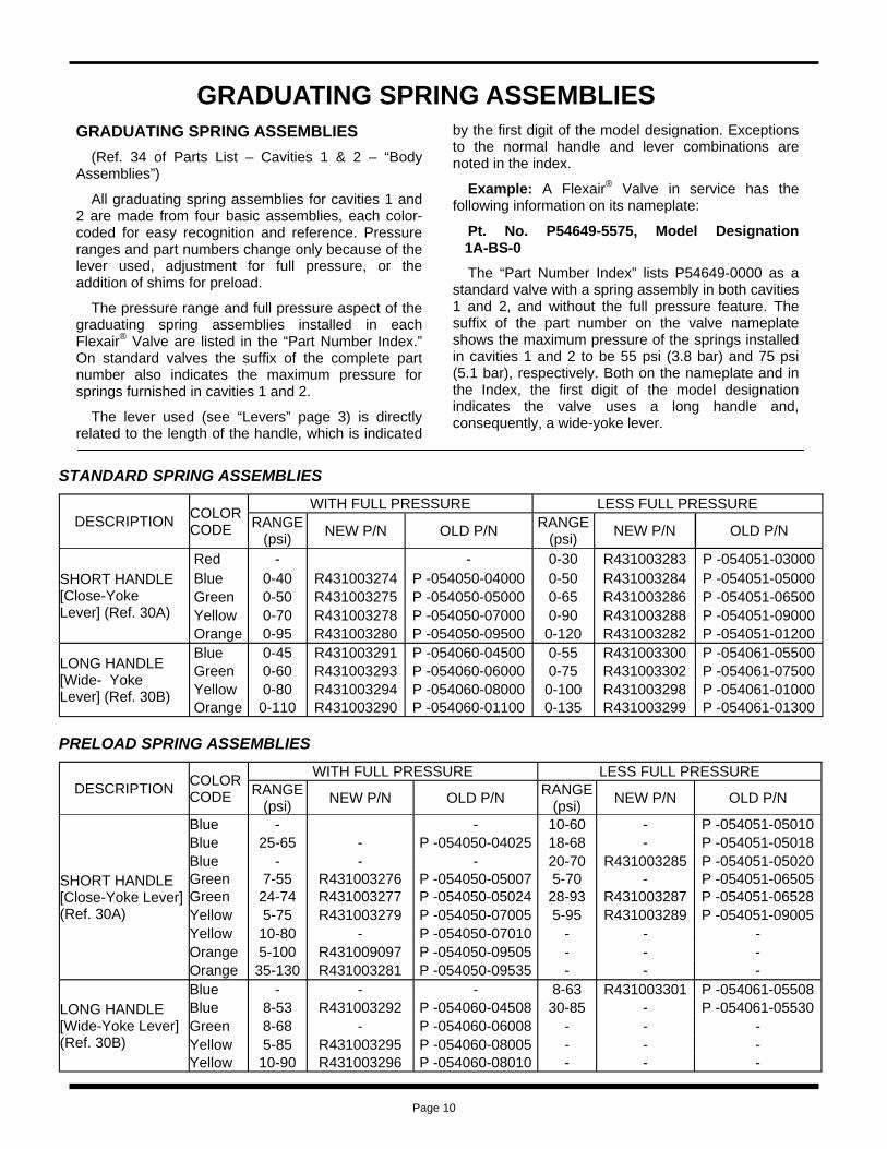
GRADUATING SPRING ASSEMBLIES
DESCRIPTION COLOR CODE
WITH FULL PRESSURE LESS FULL PRESSURE RANGE
(psi) NEW P/N OLD P/N RANGE (psi) NEW P/N OLD P/N
SHORT HANDLE [Close-Yoke Lever] (Ref. 30A)
Red - - 0-30 R431003283 P -054051-03000 Blue 0-40 R431003274 P -054050-04000 0-50 R431003284 P -054051-05000 Green 0-50 R431003275 P -054050-05000 0-65 R431003286 P -054051-06500 Yellow 0-70 R431003278 P -054050-07000 0-90 R431003288 P -054051-09000 Orange 0-95 R431003280 P -054050-09500 0-120 R431003282 P -054051-01200
LONG HANDLE [Wide- Yoke Lever] (Ref. 30B)
Blue 0-45 R431003291 P -054060-04500 0-55 R431003300 P -054061-05500 Green 0-60 R431003293 P -054060-06000 0-75 R431003302 P -054061-07500 Yellow 0-80 R431003294 P -054060-08000 0-100 R431003298 P -054061-01000 Orange 0-110 R431003290 P -054060-01100 0-135 R431003299 P -054061-01300
STANDARD SPRING ASSEMBLIES
DESCRIPTION COLOR CODE
WITH FULL PRESSURE LESS FULL PRESSURE RANGE
(psi) NEW P/N OLD P/N RANGE (psi) NEW P/N OLD P/N
SHORT HANDLE [Close-Yoke Lever] (Ref. 30A)
Blue - - 10-60 - P -054051-05010 Blue 25-65 - P -054050-04025 18-68 - P -054051-05018 Blue - - - 20-70 R431003285 P -054051-05020 Green 7-55 R431003276 P -054050-05007 5-70 - P -054051-06505 Green 24-74 R431003277 P -054050-05024 28-93 R431003287 P -054051-06528 Yellow 5-75 R431003279 P -054050-07005 5-95 R431003289 P -054051-09005 Yellow 10-80 - P -054050-07010 - - - Orange 5-100 R431009097 P -054050-09505 - - - Orange 35-130 R431003281 P -054050-09535 - - -
LONG HANDLE[Wide-Yoke Lever] (Ref. 30B)
Blue - - - 8-63 R431003301 P -054061-05508 Blue 8-53 R431003292 P -054060-04508 30-85 - P -054061-05530 Green 8-68 - P -054060-06008 - - - Yellow 5-85 R431003295 P -054060-08005 - - - Yellow 10-90 R431003296 P -054060-08010 - - -
PRELOAD SPRING ASSEMBLIES
GRADUATING SPRING ASSEMBLIES (Ref. 34 of Parts List – Cavities 1 & 2 – “Body
Assemblies”)
All graduating spring assemblies for cavities 1 and 2 are made from four basic assemblies, each color-coded for easy recognition and reference. Pressure ranges and part numbers change only because of the lever used, adjustment for full pressure, or the addition of shims for preload.
The pressure range and full pressure aspect of the graduating spring assemblies installed in each Flexair® Valve are listed in the “Part Number Index.” On standard valves the suffix of the complete part number also indicates the maximum pressure for springs furnished in cavities 1 and 2.
The lever used (see “Levers” page 3) is directly related to the length of the handle, which is indicated
by the first digit of the model designation. Exceptions to the normal handle and lever combinations are noted in the index.
Example: A Flexair® Valve in service has the following information on its nameplate:
Pt. No. P54649-5575, Model Designation 1A-BS-0
The “Part Number Index” lists P54649-0000 as a standard valve with a spring assembly in both cavities 1 and 2, and without the full pressure feature. The suffix of the part number on the valve nameplate shows the maximum pressure of the springs installed in cavities 1 and 2 to be 55 psi (3.8 bar) and 75 psi (5.1 bar), respectively. Both on the nameplate and in the Index, the first digit of the model designation indicates the valve uses a long handle and, consequently, a wide-yoke lever.
Page 10
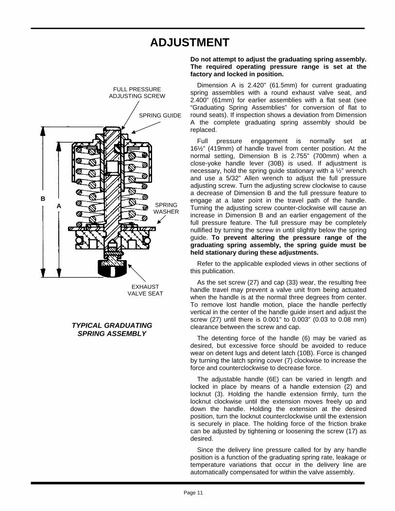
ADJUSTMENT Do not attempt to adjust the graduating spring assembly. The required operating pressure range is set at the factory and locked in position.
Dimension A is 2.420” (61.5mm) for current graduating spring assemblies with a round exhaust valve seat, and 2.400” (61mm) for earlier assemblies with a flat seat (see “Graduating Spring Assemblies” for conversion of flat to round seats). If inspection shows a deviation from Dimension A the complete graduating spring assembly should be replaced.
Full pressure engagement is normally set at 16½” (419mm) of handle travel from center position. At the normal setting, Dimension B is 2.755” (700mm) when a close-yoke handle lever (30B) is used. If adjustment is necessary, hold the spring guide stationary with a ½” wrench and use a 5/32” Allen wrench to adjust the full pressure adjusting screw. Turn the adjusting screw clockwise to cause a decrease of Dimension B and the full pressure feature to engage at a later point in the travel path of the handle. Turning the adjusting screw counter-clockwise will cause an increase in Dimension B and an earlier engagement of the full pressure feature. The full pressure may be completely nullified by turning the screw in until slightly below the spring guide. To prevent altering the pressure range of the graduating spring assembly, the spring guide must be held stationary during these adjustments.
Refer to the applicable exploded views in other sections of this publication.
As the set screw (27) and cap (33) wear, the resulting free handle travel may prevent a valve unit from being actuated when the handle is at the normal three degrees from center. To remove lost handle motion, place the handle perfectly vertical in the center of the handle guide insert and adjust the screw (27) until there is 0.001” to 0.003” (0.03 to 0.08 mm) clearance between the screw and cap.
The detenting force of the handle (6) may be varied as desired, but excessive force should be avoided to reduce wear on detent lugs and detent latch (10B). Force is changed by turning the latch spring cover (7) clockwise to increase the force and counterclockwise to decrease force.
The adjustable handle (6E) can be varied in length and locked in place by means of a handle extension (2) and locknut (3). Holding the handle extension firmly, turn the locknut clockwise until the extension moves freely up and down the handle. Holding the extension at the desired position, turn the locknut counterclockwise until the extension is securely in place. The holding force of the friction brake can be adjusted by tightening or loosening the screw (17) as desired.
Since the delivery line pressure called for by any handle position is a function of the graduating spring rate, leakage or temperature variations that occur in the delivery line are automatically compensated for within the valve assembly.
FULL PRESSURE ADJUSTING SCREW
SPRING GUIDE
SPRING WASHER
EXHAUST VALVE SEAT
TYPICAL GRADUATING SPRING ASSEMBLY
B A
Page 11

OBSOLETE ASSEMBLIES AND DESIGN CHANGES
REF. NO. DESCRIPTION 34B SEAT, Exhaust valve (not shown) 34C CLIP 41 PLUNGER, Valve
OBSOLETE ASSEMBLIES The detent latch was originally designed cross-
slotted to accommodate a lever with pin. By rotating the latch 90° the handle detent feature could be nullified.
Subsequently, the handle lever was redesigned with a key slot instead of a pin hole. Concurrently, the detent latch was redesigned with a T slot for use with either a pin (new size) on the old lever or key on the new lever. The keyed lever also required rotating the latch 90° to nullify the detent feature. Since the T slotted latch could not be rotated on the pinned lever, a retainer (9C) was substituted when a replacement latch was required for non-detented handle operation using the pinned lever. Later still, levers were furnished with both a key slot and a pin hole.
On the current design, the T slotted detent latch and the retainer have been retained, but the key slot in the lever has been omitted in favor of the pin and hole. Keys are not recommended as a service part, and their replacement with the current lever and pin is urged.
GRADUATING SPRING ASSEMBLIES The current graduating spring assemblies listed on
the facing page include a rounded exhaust valve seat. This rounded seat is used with the current valve plunger, Part No. R431006833 (Old Part No. P -066554-00000) (see Ref. 41 of Parts List – “Body Assemblies”).
IMPORTANT: These two assemblies are inter-changeable, but the exhaust valve seat is compatible only with its associated plunger because important tolerances are involved.
If replacement of the complete graduating spring assembly is required, make sure the current valve plunger in used. If only repair of an assembly with a flat seat is necessary, convert as follows, using the
DESIGN CHANGES AFFECTING REPLACEMENT
SPRING VALVE SEAT CONVERSION KIT, Complete: R431005262 (P -059835-00000)
Obsolete
Obsolete 11B
9B 9C
Obsolete
CURRENT ASSEMBLY
OBSOLETE ASSEMBLY
Clip
Rounded Seat
Rivet
Flat Seat
Page 12

ACCESSORIES
New P/N R431003026 (Old P/N P -052875-00000)
REF. NO. QTY DESCRIPTION 1 1 BAND 2 4 RETAINER, Grip nut 3 4 SCREW, Hex nut 4 4 WASHER, Lock 5 2 BRACKET, Panel mounting
Panel Mounting Kit, Complete:
Early model Flexair® Valves were made with a cast iron body, and mounting dimensions were different from current models; however, the current valve can be used as a direct replacement for an early model by using the kits below. Complete Mounting Adapter Kit (R431003978) adapts the mounting holes on the current valve to the bolt pattern of the cast iron model. Kit R431003979 more closely approximates the handle position of the cast iron model.
REF. NO. QTY DESCRIPTION 1 4 SCREW
2A 1 PLATE, Mounting adapter (for R431003978) 2B 1 PLATE, Mounting adapter (for R431003979)
REF. NO. QTY DESCRIPTION 1 1 HANDLE 2 1 HANDLE ASSEMBLY 3 1 LOCKNUT 4 1 PIN, Spirol
QTY DESCRIPTION 4 SCREW, Self-tapping 2 ADAPTER, Exhaust
REF. NO. 1 2
Mounting Adapter Kits: New P/N R431003978 (Old P/N P -057013-00000) & New P/N R431003979 (Old P/N P -057013-00001)
Exhaust Adapter Kit, Complete: New P/N R431005756 (Old P/N P -061340-00000)
Adjustable Handle Kit, Complete: New P/N R431003981(Old P/N P -057058-00000)
1
5
2
3
1
1
2B
2A
Kit Part No. R431003979 (common bolt pattern and handle height)
2
1 5
2
1
3
4
Kit Part No. R431003978 (common bolt pattern)
4
Page 13
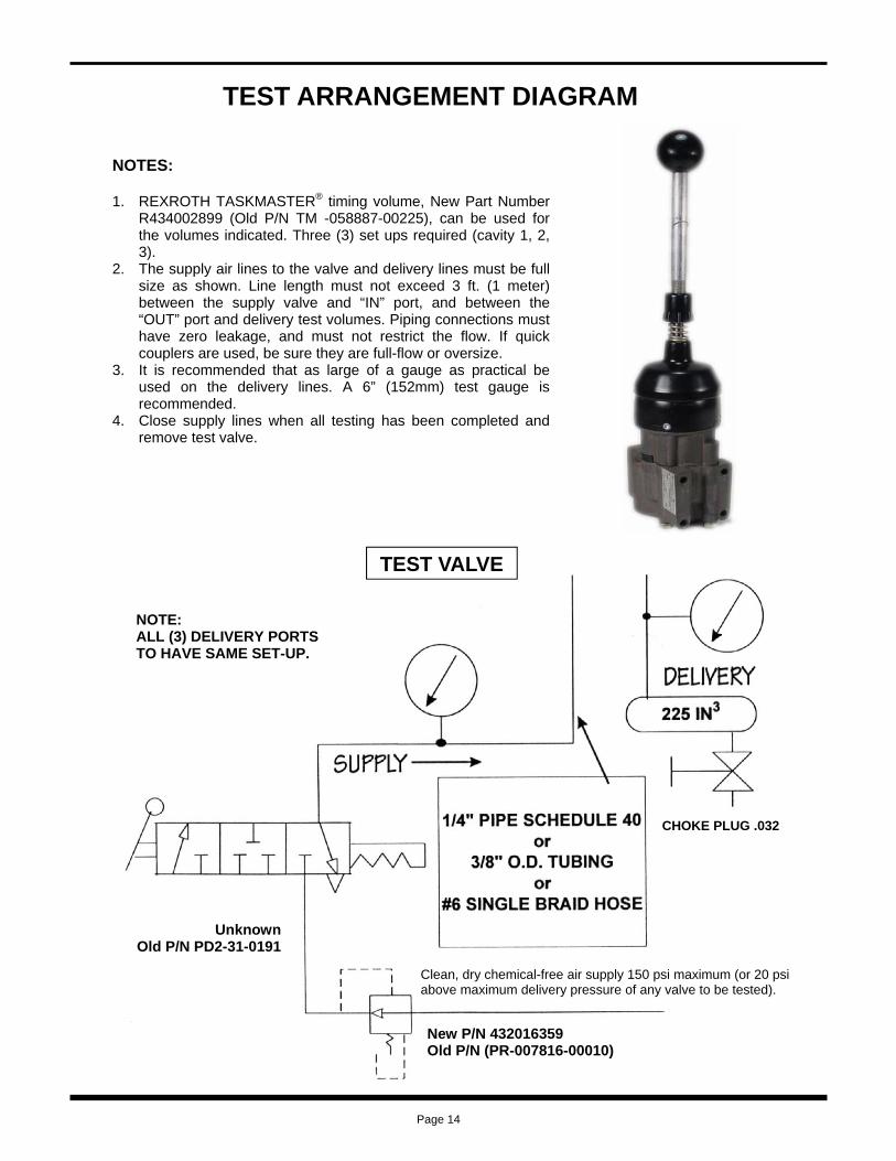
TEST ARRANGEMENT DIAGRAM
NOTES: 1. REXROTH TASKMASTER® timing volume, New Part Number
R434002899 (Old P/N TM -058887-00225), can be used for the volumes indicated. Three (3) set ups required (cavity 1, 2, 3).
2. The supply air lines to the valve and delivery lines must be full size as shown. Line length must not exceed 3 ft. (1 meter) between the supply valve and “IN” port, and between the “OUT” port and delivery test volumes. Piping connections must have zero leakage, and must not restrict the flow. If quick couplers are used, be sure they are full-flow or oversize.
3. It is recommended that as large of a gauge as practical be used on the delivery lines. A 6” (152mm) test gauge is recommended.
4. Close supply lines when all testing has been completed and remove test valve.
TEST VALVE
NOTE: ALL (3) DELIVERY PORTS TO HAVE SAME SET-UP.
CHOKE PLUG .032
Clean, dry chemical-free air supply 150 psi maximum (or 20 psi above maximum delivery pressure of any valve to be tested).
Unknown Old P/N PD2-31-0191
New P/N 432016359 Old P/N (PR-007816-00010)
Page 14

TESTING AND TEST SETUP
After any repair or adjustment, the Flexair® Valve should be tested using procedures and test arrangements described in this section. Pressure control valves of this nature should be tested for the following:
1. Function
2. Pressure range
3. Leakage
4. Response
5. Mechanical detent
6. Spring return models
7. Friction models
The adjustments affecting these points have been described in the previous section. General instructions for accomplishing the above tests follow.
1. Function: The Flexair Valves are spring returned, 3 way pressure graduating valves. A handle actuates the valve to increase, decrease or maintain graduated air pressure to the delivery line. This function should be checked using test arrangement shown.
2. Pressure range – Cavities 1, 2 & 3: Supply pressure at “IN” port will be delivered as graduated pressure to “OUT” port delivery line depending on range of control spring being used and handle position. In handle release position the “OUT” line is at zero pressure setting. Moving the handle actuates the graduating control portion to deliver graduated pressure to the “OUT” line. See “Adjustment” (page 11) to adjust the valve. After valve is adjusted, check that minimum and maximum pressure ranges are generated in delivery line per valve part number.
3. Leakage: Set supply pressure to 20 psi (1.4 bar) above maximum delivery pressure of valve being tested. Using soap solution, coat the valve at pipe bracket and spring housing parting lines. No leakage is permitted in any handle position. 3a. On all valves with spring ranges less than 100 psi (6.9 bar), set supply line pressure to 100 psi (6.9 bar). Move handle to full travel position and hold. Close valve in supply line to “IN” port, and valve in delivery line from “OUT” port to trap the supply pressure at the valve. Observe the “OUT” delivery line pressure gauge. A pressure drop of no more than 3 psi (0.2 bar) in 30 seconds is0permitted.
3b. On all valves with spring ranges 100 psi (6.9 bar) and above, set supply line pressure to 100 psi (6.9 bar). Move handle to deliver 95 psi (6.5 bar) to delivery line from “OUT” port. Close valve in supply line to “IN” port, and valve in delivery line from “OUT” port to trap the supply pressure at the valve. Observe the “OUT” delivery line pressure gauge. A pressure drop of no more than 3 psi (0.2 bar) in 30 seconds is permitted.
4. Response: Move handle to full travel position. Fully open the valve at delivery volume so that air exhausts through the choke plug. Observe the delivery line pressure gauge. A pressure drop of no more than 3 psi (0.2 bar) is permitted. Release handle.
5. Mechanical detent: (“D” Models only) Connect a spring scale just under the knob. Move handle from neutral position to Position #1. A minimum of 4 to 6 lbs. (1.8 to 2.7 kg) should be required to pull handle until 30 psi (2.0 bar) output is indicated. Adjust detent knob to proper load. Repeat by moving handle toward Position #2.
6. Spring return models: Must return to center position from all positions when released.
7. Friction models: Must remain in any position that the handle is in.
Page 15

REPAIR AND CONVERSION KITS
These repair kits renew the elastomer seals and some common wear parts of the component. On damaged or severely worn valves, additional parts may be required.
DESCRIPTION OLD P/N Repair Kit, Common Parts P -053460-00003 Repair Kit, Detent P -053460-00002 Repair Kit, Cavities 1 & 2 P -053460-00001 Repair Kit, Handle P -057058-00000 Repair Kit, Major Cavity 3, Graduated P -053460-00008
Repair Kit, Major Cavity 3, 3-Way P -053460-00007
Repair Kit, Minor Cavity 3, Graduated P -053460-00006
Repair Kit, Minor Cavity 3, 3-Way P -055474-00002
BASIC KITS NEW P/N
R431003221 R431003220 R431003219 R431003981
R431003224
R431003223
R431003222
R431003741
WHEN DIGITS ARE
MAJOR REPAIR KIT PART NO.
QTY DESCRIPTION
MAJOR REPAIR KIT
1 REPAIR KIT, Common Parts 1 REPAIR KIT, Detent 1 REPAIR KIT, Cavities 1 & 2
R431004963 (P -059301-00001) MAJOR REPAIR KIT
1 REPAIR KIT, Common Parts 1 REPAIR KIT, Cavities 1 & 2
R431004964 (P -059301-00002) MAJOR REPAIR KIT
1 REPAIR KIT, Common Parts 1 REPAIR KIT, Detent 2 REPAIR KIT, Cavities 1 & 2
R431004965 (P -059301-00003) MAJOR REPAIR KIT
1 REPAIR KIT, Common Parts 1 REPAIR KIT, Cavities 1 & 2
Use kit R431004966 (P -059301-00012) when cavity 3 is 3-way
Use kit R431004967 (P -059301-00013) when cavity 3 graduated
1 REPAIR KIT, Common Parts 1 REPAIR KIT, Detent 1 REPAIR KIT, Cavities 1 & 2 1 REPAIR KIT, Cavity 3
Use kit R431004968 (P -059301-00014) when cavity 3 is 3-way
1 REPAIR KIT, Common Parts 1 REPAIR KIT, Cavities 1 & 2 1 REPAIR KIT, Cavity 3
Use kit R431004970 (P -059301-00016) when cavity 3 is 3-way
1 REPAIR KIT, Common Parts
1 REPAIR KIT, Detent 2 REPAIR KIT, Cavities 1 & 2 1 REPAIR KIT, Cavity 3
Use kit R431004972 (P -059301-00018) when cavity 3 is 3-way
1 REPAIR KIT, Common Parts 1 REPAIR KIT, Cavities 1 & 2 1 REPAIR KIT, Cavity 3
R431004962 (P -059301-00000)
Use kit R431004969 (P -059301-00015) when cavity 3 graduated
Use kit R431004973 (P -059301-00019 when cavity 3 graduated
Use kit R431004971 (P -059301-00017) when cavity 3 graduated
WHEN DIGITS ARE:
MAJOR REPAIR
KIT PART NO.
QTY DESCRIPTION
1 REPAIR KIT, Common Parts 1 REPAIR KIT, Cavities 1 & 2 1 REPAIR KIT, Cavity 3 Use kit R431004970 (P -059301-00016)
when cavity 3 is 3-way
1 REPAIR KIT, Common Parts 1 REPAIR KIT, Detent 2 REPAIR KIT, Cavities 1 & 2 1 REPAIR KIT, Cavity 3 Use kit R431004972 (P -059301-00018)
when cavity 3 is 3-way
1 REPAIR KIT, Common Parts 1 REPAIR KIT, Cavities 1 & 2 1 REPAIR KIT, Cavity 3
Use kit R431004969 (P -059301-00015) when cavity 3 graduated
Use kit R431004968 ( -0P59301-00014) when cavity 3 is 3-way
Use kit R431004966 (P -059301-00012) when cavity 3 is 3-way
Use kit R431004967 (P -059301-00013) when cavity 3 graduated
1 REPAIR KIT, Common Parts 1 REPAIR KIT, Detent 1 REPAIR KIT, Cavities 1 & 2 1 REPAIR KIT, Cavity 3
Use kit R431004971 (P -059301-00017) when cavity 3 graduated
Use kit R431004973 (P -059301-00019) when cavity 3 graduated
Major repair kits, which include applicable kits, are listed by the part number of each valve in the “Part Number Index.” When these kits are installed as recommended, the result is a fully rebuilt and current Flexair® Valve.
When partial repairs are desired, the basic repair kits that follow should provide adequate selection. All major kits for Flexair Valves are made up from these six basic kits. The major kits listed in the index are identified here by valve model designation and show the basic kits they include.
D
A 0 F
or
A S 0
D
B 0
F
or
F
or
2
- or
2
- or
2
B
F
or
2
- or
1
B S
2
1
F
-or
2
- or
2
- or
1
MAJOR REPAIR KITS
D 1
F
or
2
D
A
1
- or
A
1
- or S A
D 1
D
B
B S
1
A S
B S 0
Page 16
-

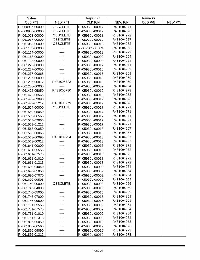
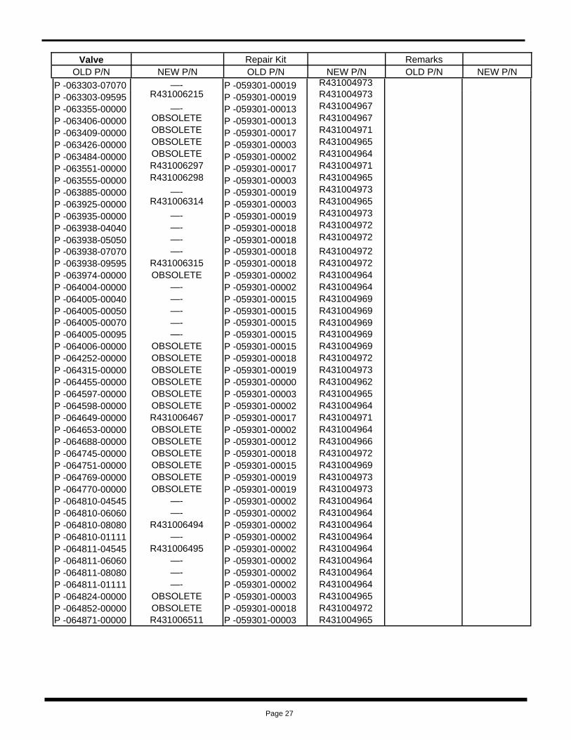
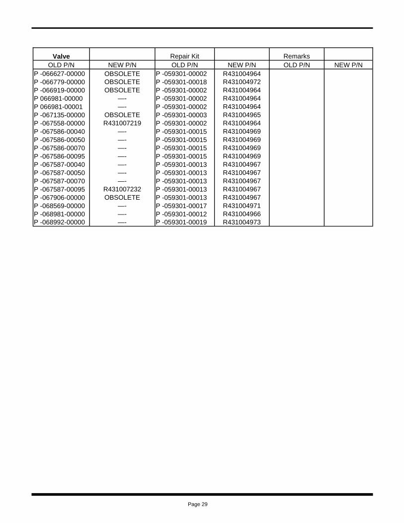
These repair kits renew the elastomer seals and some common wear parts of the component. On damaged or severely worn valves, additional parts may be required. Complete part numbers of most Flexair® Valves in service are listed numerically in the following index. For part numbers not listed, consult the factory.
Major repair kits, which include necessary conversion kits, if applicable, are listed beside the complete part number of each valve. When these kits are installed as recommended, the result is a fully rebuilt, current Flexair Valve. If partial repairs are desired, see “Repair and Conversion Kits” page 16 for selection.
PART NUMBER CODE NOTE: Obsolete part numbers are noted “Obs.” – for service parts only – cannot be purchased. The construction of each valve is indicated by the model designation (see “Model Designation Code”). Additional information on each valve is indicated by the suffix of the complete ptn as follows:
SUFFIX: 0000 Standard valve with a current valve unit cavity 3, if filled. The pressure range on a standard valve may range from zero to any maximum delivery pressure with the design limitations of the valve. On the nameplate of a standard valve, the 4-digit suffix (replacing the 4 zeroes) of the complete part number indicates the maximum delivery pressure in psi of the graduated valve units in cavities 1 & 2. The 1st and 2nd digits apply to cavity 1, and the 3rd and 4th to cavity 2. When the digits are:
40-95 Actual maximum pressure 10-12 Multiply times 10 for actual maximum pressure 13 Maximum pressure is 135 psi. (9.3 bar) 1 digit or none Non-standard valve with obsolete details in cavity 3, if filled (a few exceptions appear, but the major repair kits listed are appropriate). Pressure ranges listed in the Index are fixed and not stamped on the valve nameplate. 000 & 4th digit Non-standard valve with a current valve unit in cavity 3. Pressure ranges listed are fixed and not stamped on the valve nameplate.
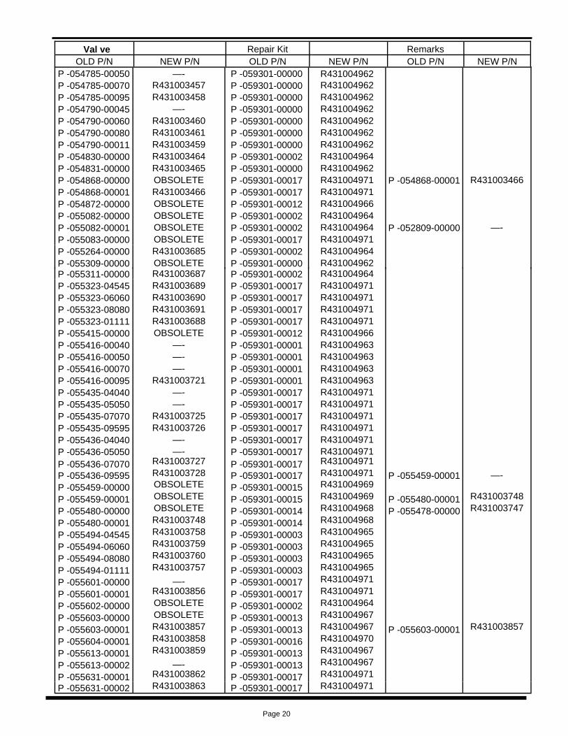
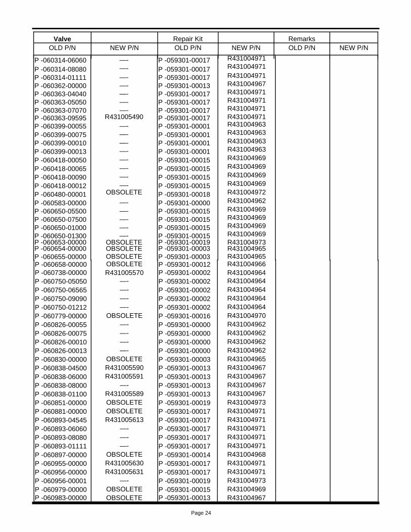
PART NUMBER INDEX
Valve Repair Kit Remarks OLD P/N NEW P/N OLD P/N NEW P/N OLD P/N NEW P/N
P -052735-04545 R431002990 P -059301-00016 R431004970 P -052735-06060 R431002991 P -059301-00016 R431004970 P -052735-08080 R431002992 P -059301-00016 R431004970 P -052735-01111 R431002989 P -059301-00016 R431004970 P -052772-04545 R431002997 P -059301-00002 R431004964 P -052772-06060 R431002998 P -059301-00002 R431004964 P -052772-08080 R431002999 P -059301-00002 R431004964 P -052772-08011 —- P -059301-00002 R431004964 P -052772-01111 R431002996 P -059301-00002 R431004964 P -052783-04545 —- P -059301-00016 R431004970 P -052783-06060 —- P -059301-00016 R431004970 P -052783-08080 R431003002 P -059301-00016 R431004970 P -052783-01111 R431003001 P -059301-00016 R431004970 p -052784-00000 OBSOLETE P -052785-00000 OBSOLETE P -052785-00001 R431003003 P -052785-00001 R431003003 P -059301-00000 R431004962 P -052786-00000 OBSOLETE P -059301-00012 R431004966 P -052809-04040 R431003007 P -059301-00002 R431004964 P -052809-05050 —- P -059301-00002 R431004964 P -052809-07070 R431003008 P -059301-00002 R431004964 P -052809-09595 R431003009 P -059301-00002 R431004964 P -052830-04040 R431003011 P -059301-00016 R431004970 P -052830-05050 —- P -059301-00016 R431004970 P -052830-07070 R431003012 P -059301-00016 R431004970 P -052830-09595 R431003013 P -059301-00016 R431004970
Page 17

Page 18
P -052867-00000 R431003020 P -059301-00002 R431004964 P -052867-00001 OBSOLETE P -052867-00002 R431003021 P -052867-00002 R431003021 P -059301-00002 R431004964 P -052867-00003 R431003022 P -059301-00002 R431004964 P -052868-00000 OBSOLETE P -052868-00001 R431003023 P -059301-00002 R431004964 P -052868-00001 R431003023 P -052948-00000 OBSOLETE P -059301-00016 R431004970 P -053082-04040 —- P -059301-00017 R431004971 P -053082-05050 R431003097 P -059301-00017 R431004971 P -053082-07070 —- P -059301-00017 R431004971 P -053082-09595 —- P -059301-00017 R431004971 P -053087-00000 OBSOLETE P -059301-00002 R431004964 P -052772-00000 —- P -053127-05050 R431003110 P -059301-00002 R431004964 P -053127-06565 R431003111 P -059301-00002 R431004964 P -053127-09090 R431003112 P -059301-00002 R431004964 P -053127-01212 R431003109 P -059301-00002 R431004964 P -053266-00000 OBSOLETE P -059301-00017 R431004971 P -053268-04040 —- P -059301-00017 R431004971 P -053268-05050 —- P -059301-00017 R431004971 P -053268-07070 R431003146 P -059301-00017 R431004971 P -053268-09595 R431003147 P -059301-00017 R431004971 P -053485-04040 —- P -059301-00003 R431004965 P -053485-05050 R431003239 P -059301-00003 R431004965 P -053485-07070 —- P -059301-00003 R431004965 P -053485-09595 R431003240 P -059301-00003 R431004965 P -053488-00000 OBSOLETE P -059301-00001 R431004963 P -053791-00050 R431003250 P -059301-00000 R431004962 P -053791-00065 —- P -059301-00000 R431004962 P -053791-00090 R431003251 P -059301-00000 R431004962 P -053791-00012 R431003249 P -059301-00000 R431004962 P -054089-00000 OBSOLETE P -059301-00012 R431004966 P -054173-00009 —- P -054092-05050 —- P -059301-00017 R431004971 P -054092-06565 —- P -059301-00017 R431004971 P -054092-09090 R431003304 P -059301-00017 R431004971 P -054092-01212 —- P -059301-00017 R431004971 P -054157-05050 R431003308 P -059301-00002 R431004964 P -054157-06565 R431003309 P -059301-00002 R431004964 P -054157-09090 R431003310 P -059301-00002 R431004964 P -054157-01212 R431003307 P -059301-00002 R431004964 P -054177-00000 OBSOLETE P -059301-00001 R431004963 P -054589-00001 —- P -054589-00000 OBSOLETE P -054589-00001 OBSOLETE P -059301-00002 R431004964 P -054589-00002 R431003388 P -059301-00003 R431004965 P -054649-05555 —- P -059301-00002 R431004964 P -054649-07575 —- P -059301-00002 R431004964 P -054649-01010 R431003410 P -059301-00002 R431004964 P -054649-01313 R431003411 P -059301-00002 R431004964 P -054656-00000 R431003415 P -059301-00002 R431004964 P -054657-05050 R431003417 P -059301-00003 R431004965 P -054657-06565 R431003418 P -059301-00003 R431004965 P -054657-09090 R431003419 P -059301-00003 R431004965 P -054657-01212 R431003416 P -059301-00003 R431004965
Val ve Repair Kit Remarks OLD P/N NEW P/N OLD P/N NEW P/N OLD P/N NEW P/N

Page 19
P -054658-00050 —- P -059301-00001 R431004963 P -054658-00065 —- P -059301-00001 R431004963 P -054658-00090 R431003422 P -059301-00001 R431004963 P -054658-00012 R431003420 P -059301-00001 R431004963 P -054699-00000 OBSOLETE P -059301-00002 R431004964 P -054700-00000 OBSOLETE P -059301-00016 R431004970 P -054701-00000 OBSOLETE P -059301-00001 R431004963 P -054707-00000 R431003446 P -059301-00002 R431004964 P -054725-04040 —- P -059301-00002 R431004964 P -054725-05050 —- P -059301-00002 R431004964 P -054725-07070 R431003447 P -059301-00002 R431004964 P -054725-09595 R431003448 P -059301-00002 R431004964 P -054726-00050 —- P -059301-00013 R431004967 P -054726-00065 —- P -059301-00013 R431004967 P -054726-00090 —- P -059301-00013 R431004967 P -054726-00012 —- P -059301-00013 R431004967 P -054727-00040 —- P -059301-00013 R431004967 P -054727-00050 —- P -059301-00013 R431004967 P -054727-00070 —- P -059301-00013 R431004967 P -054727-00095 —- P -059301-00013 R431004967 P -054728-04040 —- P -059301-00013 R431004967 P -054728-05050 —- P -059301-00017 R431004971 P -054728-07070 —- P -059301-00017 R431004971 P -054728-09595 R431003449 P -059301-00017 R431004971 P -054729-00000 OBSOLETE P -059301-00016 R431004970 P -054730-00000 OBSOLETE P -059301-00016 R431004970 P -054731-00000 OBSOLETE P -059301-00016 R431004970 P -054732-00000 OBSOLETE P -059301-00017 R431004971 P -054733-00000 OBSOLETE P -059301-00016 R431004970 P -054734-00000 OBSOLETE P -059301-00017 R431004971 P -054735-00000 OBSOLETE P -059301-00017 R431004971 P -054736-00050 R431003450 P -059301-00000 R431004962 P -054736-00065 R431003451 P -059301-00000 R431004962 P -054736-00090 R431003452 P -059301-00000 R431004962 P -054736-00012 —- P -059301-00000 R431004962 P -054737-05050 —- P -059301-00002 R431004964 P -054737-06565 R431009109 P -059301-00002 R431004964 P -054737-09090 —- P -059301-00002 R431004964 P -054737-01212 —- P -059301-00002 R431004964 P -054738-04040 —- P -059301-00002 R431004964 P -054738-05050 —- P -059301-00002 R431004964 P -054738-07070 —- P -059301-00002 R431004964 P -054738-09595 —- P -059301-00002 R431004964 P -054766-00000 R431003454 P -059301-00002 R431004964 P -054656-00000 R431003415 P -054770-00000 —- P -059301-00000 R431004962 P -054775-00001 OBSOLETE P -059301-00016 R431004970 P -054775-00002 R431003455 P -059301-00016 R431004970 P -054776-00000 —- P -059301-00017 R431004971 P -054776-00002 R431003456 P -059301-00017 R431004971 P -054777-00000 OBSOLETE P -059301-00017 R431004971 P -054777-00001 OBSOLETE P -059301-00017 R431004971 P -054777-00002 —- P -059301-00017 R431004971 P -054785-00040 —- P -059301-00000 R431004962
Val ve Repair Kit Remarks OLD P/N NEW P/N OLD P/N NEW P/N OLD P/N NEW P/N
Page 20
P -054785-00050 —- P -059301-00000 R431004962 P -054785-00070 R431003457 P -059301-00000 R431004962 P -054785-00095 R431003458 P -059301-00000 R431004962 P -054790-00045 —- P -059301-00000 R431004962 P -054790-00060 R431003460 P -059301-00000 R431004962 P -054790-00080 R431003461 P -059301-00000 R431004962 P -054790-00011 R431003459 P -059301-00000 R431004962 P -054830-00000 R431003464 P -059301-00002 R431004964 P -054831-00000 R431003465 P -059301-00000 R431004962 P -054868-00000 OBSOLETE P -059301-00017 R431004971 P -054868-00001 R431003466 P -054868-00001 R431003466 P -059301-00017 R431004971 P -054872-00000 OBSOLETE P -059301-00012 R431004966 P -055082-00000 OBSOLETE P -059301-00002 R431004964 P -055082-00001 OBSOLETE P -059301-00002 R431004964 P -052809-00000 —- P -055083-00000 OBSOLETE P -059301-00017 R431004971 P -055264-00000 R431003685 P -059301-00002 R431004964 P -055309-00000 OBSOLETE P -059301-00000 R431004962
Val ve Repair Kit Remarks OLD P/N NEW P/N OLD P/N NEW P/N OLD P/N NEW P/N
P -055311-00000 R431003687 P -059301-00002 R431004964 P -055323-04545 R431003689 P -059301-00017 R431004971 P -055323-06060 R431003690 P -059301-00017 R431004971 P -055323-08080 R431003691 P -059301-00017 R431004971 P -055323-01111 R431003688 P -059301-00017 R431004971 P -055415-00000 OBSOLETE P -059301-00012 R431004966 P -055416-00040 —- P -059301-00001 R431004963 P -055416-00050 —- P -059301-00001 R431004963 P -055416-00070 —- P -059301-00001 R431004963 P -055416-00095 R431003721 P -059301-00001 R431004963 P -055435-04040 —- P -059301-00017 R431004971 P -055435-05050 —- P -059301-00017 R431004971 P -055435-07070 R431003725 P -059301-00017 R431004971 P -055435-09595 R431003726 P -059301-00017 R431004971 P -055436-04040 —- P -059301-00017 R431004971 P -055436-05050 —- P -059301-00017 R431004971 P -055436-07070 R431003727 P -059301-00017 R431004971 P -055436-09595 R431003728 P -059301-00017 R431004971 P -055459-00001 —- P -055459-00000 OBSOLETE P -059301-00015 R431004969 P -055459-00001 OBSOLETE P -059301-00015 R431004969 P -055480-00001 R431003748 P -055480-00000 OBSOLETE P -059301-00014 R431004968 P -055478-00000 R431003747 P -055480-00001 R431003748 P -059301-00014 R431004968 P -055494-04545 R431003758 P -059301-00003 R431004965 P -055494-06060 R431003759 P -059301-00003 R431004965 P -055494-08080 R431003760 P -059301-00003 R431004965 P -055494-01111 R431003757 P -059301-00003 R431004965 P -055601-00000 —- P -059301-00017 R431004971 P -055601-00001 R431003856 P -059301-00017 R431004971 P -055602-00000 OBSOLETE P -059301-00002 R431004964 P -055603-00000 OBSOLETE P -059301-00013 R431004967 P -055603-00001 R431003857 P -059301-00013 R431004967 P -055603-00001 R431003857 P -055604-00001 R431003858 P -059301-00016 R431004970 P -055613-00001 R431003859 P -059301-00013 R431004967 P -055613-00002 —- P -059301-00013 R431004967 P -055631-00001 R431003862 P -059301-00017 R431004971 P -055631-00002 R431003863 P -059301-00017 R431004971

Page 21
Valve Repair Kit Remarks OLD P/N NEW P/N OLD P/N NEW P/N OLD P/N NEW P/N
P -055929-00000 OBSOLETE P -059301-00017 R431004971 P -055929-00001 OBSOLETE P -059301-00017 R431004971 P -055943-00000 OBSOLETE P -059301-00002 R431004964 P -055943-00002 R431003939 P -055943-00001 OBSOLETE P -059301-00002 R431004964 P -055943-00002 R431003939 P -055943-00002 R431003939 P -059301-00002 R431004964 P -055944-00000 OBSOLETE P -059301-00016 R431004970 P -055964-00000 OBSOLETE P -059301-00003 R431004965 P -056171-00040 R431003962 P -059301-00000 R431004962 P -056171-00050 —- P -059301-00000 R431004962 P -056171-00070 —- P -059301-00000 R431004962 P -056171-00095 R431003963 P -059301-00000 R431004962 P -056191-00000 OBSOLETE P -059301-00018 R431004972 P -056249-04040 —- P -059301-00018 R431004972 P -056249-05050 —- P -059301-00018 R431004972 P -056249-07070 —- P -059301-00018 R431004972 P -056249-09595 —- P -059301-00018 R431004972 P -056278-00000 OBSOLETE P -059301-00018 R431004972 P -056315-00000 OBSOLETE P -059301-00019 R431004973 P -056425-04040 R431003966 P -059301-00016 R431004970 P -056425-05050 —- P -059301-00016 R431004970 P -056425-07070 —- P -059301-00016 R431004970 P -056425-09595 —- P -059301-00016 R431004970 P -057000-00000 OBSOLETE P -059301-00003 R431004965 P -057004-00000 OBSOLETE P -059301-00019 R431004973 P -057011-00000 OBSOLETE P -059301-00000 R431004962 P -057042-00000 OBSOLETE P -059301-00017 R431004971 P -057046-00000 OBSOLETE P -059301-00000 R431004962 P -057051-00000 OBSOLETE P -059301-00017 R431004971 P -057055-00000 OBSOLETE P -059301-00015 R431004969 P -057101-00000 OBSOLETE P -059301-00012 R431004966 P -057101-00001 —- P -057101-00001 —- P -059301-00012 R431004966 P -053147-00000 R431003122 P -057116-00000 OBSOLETE P -059301-00002 R431004964 P -057142-00000 OBSOLETE P -059301-00003 R431004965 P -057143-00000 OBSOLETE P -059301-00001 R431004963 P -057154-00000 OBSOLETE P -059301-00019 R431004973 P -057158-00000 OBSOLETE P -059301-00013 R431004967 P -057158-00002 —- P -057158-00001 OBSOLETE P -059301-00013 R431004967 P -057158-00002 —- P -057158-00002 —- P -059301-00013 R431004967 P -057160-00000 OBSOLETE P -059301-00017 R431004971 P -057160-00001 R431004012 P -057160-00001 R431004012 P -059301-00017 R431004971 P -057175-00000 OBSOLETE P -059301-00018 R431004972 P -053153-00000 R431003128 P -057177-00000 OBSOLETE P -059301-00013 R431004967 P -057178-00000 OBSOLETE P -059301-00013 R431004967 P -057248-04040 OBSOLETE P -059301-00016 R431004970 P -057249-00000 OBSOLETE P -059301-00003 R431004965 P -057260-00000 OBSOLETE P -059301-00016 R431004970 P -057475-00000 OBSOLETE P -059301-00002 R431004964 P -057478-00000 OBSOLETE P -059301-00015 R431004969 P -057485-00000 OBSOLETE P -059301-00013 R431004967

Page 22
P -055631-00003 R431003864 P -059301-00017 R431004971 P -055636-00001 R431003866 P -059301-00017 R431004971 P -055435-00000 —- P -055660-00000 R431003869 P -059301-00002 R431004964 P -055684-00000 OBSOLETE P -059301-00016 R431004970 P -054113-00014 —- P -055693-04545 R431003898 P -059301-00002 R431004964 P -055693-06060 R431003899 P -059301-00002 R431004964 P -055693-08080 R431003900 P -059301-00002 R431004964 P -055693-01111 R431003897 P -059301-00002 R431004964 P -055694-04545 R431003901 P -059301-00016 R431004970 P -055694-06060 —- P -059301-00016 R431004970 P -055694-08080 R431003902 P -059301-00016 R431004970 P -055694-01111 R431009012 P -059301-00016 R431004970 P -055695-04545 R431003904 P -059301-00016 R431004970 P -055695-04545 R431003904 P -059301-00016 R431004970 P -055695-06060 —- P -059301-00016 R431004970 P -055695-08080 R431003905 P -059301-00016 R431004970 P -055695-01111 R431003903 P -059301-00016 R431004970 P -055718-00000 OBSOLETE P -059301-00002 R431004964 DELETE P -055718-00001 OBSOLETE P -059301-00002 R431004964 P -055718-00002 R431003912 P -059301-00002 R431004964 P -055718-00003 OBSOLETE P -059301-00002 R431004964 P -055724-00000 OBSOLETE P -059301-00002 R431004964 P -055724-00001 OBSOLETE P -059301-00002 R431004964 P -055724-00002 OBSOLETE P -059301-00002 R431004964 P -055725-00000 OBSOLETE P -059301-00016 R431004970 DELETE P -055725-00001 OBSOLETE P -059301-00016 R431004970 DELETE P -055725-00003 OBSOLETE P -059301-00016 R431004970 P -055764-00000 OBSOLETE P -059301-00017 R431004971 P -055765-00000 OBSOLETE P -059301-00002 R431004964 P -055766-00000 OBSOLETE P -059301-00000 R431004962 P -055784-00000 OBSOLETE P -059301-00017 R431004971 DELETE P -055784-00001 OBSOLETE P -059301-00017 R431004971 P -055784-00002 OBSOLETE P -059301-00017 R431004971 P -055794-00000 OBSOLETE P -059301-00017 R431004971 DELETE P -055794-00001 OBSOLETE P -059301-00017 R431004971 P -055801-00000 R431003920 P -059301-00002 R431004964 P -055807-00000 OBSOLETE P -059301-00012 R431004966 P -055808-00000 OBSOLETE P -059301-00016 R431004970 P -055809-00000 OBSOLETE P -059301-00002 R431004964
Valve Repair Kit Remarks OLD P/N NEW P/N OLD P/N NEW P/N OLD P/N NEW P/N
P -055816-00000 OBSOLETE P -059301-00017 R431004971 DELETE P -055816-00002 OBSOLETE P -059301-00017 R431004971 P -055816-00003 OBSOLETE P -059301-00017 R431004971 P -055817-00000 R431003923 P -059301-00003 R431004965 P -055845-00000 OBSOLETE P -059301-00000 R431004962 P -055850-00000 OBSOLETE P -059301-00013 R431004967 P -055855-00000 OBSOLETE P -059301-00014 R431004968 P -055856-00000 OBSOLETE P -059301-00002 R431004964 P -055871-00000 OBSOLETE P -059301-00003 R431004965 P -055911-00000 OBSOLETE P -059301-00019 R431004973

Page 23
Valve Repair Kit Remarks OLD P/N NEW P/N OLD P/N NEW P/N OLD P/N NEW P/N
P -057526-00000 OBSOLETE P -059301-00017 R431004971 P -058489-00001 R431004547 P -057548-00000 OBSOLETE P -059301-00013 R431004967 P -057594-00000 OBSOLETE P -059301-00001 R431004963 P -057597-00000 OBSOLETE P -059301-00014 R431004968 P -057597-00001 R431004183 P -057597-00001 R431004183 P -059301-00014 R431004968 P -058388-00000 OBSOLETE P -059301-00000 R431004962 P -058440-00000 OBSOLETE P -059301-00019 R431004973 P -058489-00000 OBSOLETE P -059301-00013 P -058489-00001 R431004547 P -059301-00017 R431004971 P -058489-00001 R431004547 P -058543-00000 R431004604 P -059301-00002 R431004964 P -058544-00000 OBSOLETE P -059301-00000 R431004962 P -058545-00000 OBSOLETE P -059301-00002 R431004964 P -058550-00000 OBSOLETE P -059301-00000 R431004962 P -058626-00000 OBSOLETE P -059301-00015 R431004969 P -058631-00000 OBSOLETE P -059301-00002 R431004964 P -058631-00001 —- P -059301-00002 R431004964 P -058899-00000 OBSOLETE P -059301-00019 R431004973 P -058904-00000 OBSOLETE P -059301-00019 R431004973 P -058925-00000 R431004815 P -059301-00017 R431004971 P -058970-00000 OBSOLETE P -059301-00000 R431004962 P -058992-00001 —- P -059301-00017 R431004971 P -059057-00001 R431004891 P -059301-00019 R431004973 P -059057-00002 OBSOLETE P -059301-00018 R431004972 P -059170-00000 OBSOLETE P -059301-00017 R431004971 P -059175-00000 OBSOLETE P -059301-00019 R431004973 P -059214-00000 OBSOLETE P -059301-00019 R431004973 P -063044-00000 —- P -059294-00050 R431004950 P -059301-00015 R431004969 P -059294-00065 —- P -059301-00015 R431004969 P -059294-00090 —- P -059301-00015 R431004969 P -059294-00012 R431004949 P -059301-00015 R431004969 p -059512-00050 —- P -059301-00012 R431004966 p -059512-00065 —- P -059301-00012 R431004966 p -059512-00090 —- P -059301-00012 R431004966 p -059512-00012 —- P -059301-00012 R431004966 P -059652-00000 OBSOLETE P -059301-00018 R431004972 P -059653-00000 OBSOLETE P -059301-00019 R431004973 P -059676-04040 —- P -059301-00018 R431004972 P -056249-04040 —- P -059676-05050 —- P -059301-00018 R431004972 P -056249-05050 —- P -059676-07070 —- P -059301-00018 R431004972 P -056249-07070 —- P -059676-09595 R431005208 P -059301-00018 R431004972 P -056249-09595 —- P -059793-00001 —- P -059301-00003 R431004965 P -059825-00000 OBSOLETE P -059301-00000 R431004962 P -059836-00001 R431005264 P -059301-00016 R431004970 P -060038-00001 OBSOLETE P -059301-00017 R431004971 P -060071-00000 OBSOLETE P -059301-00016 R431004970 P -060072-00000 OBSOLETE P -059301-00016 R431004970 P -060074-00000 OBSOLETE P -059301-00003 R431004965 P -060143-04545 R431005399 P -059301-00017 R431004971 P -060143-06060 R431005400 P -059301-00017 R431004971 P -060143-08080 R431005401 P -059301-00017 R431004971 P -060143-01212 —- P -059301-00017 R431004971 P -060314-04545 —- P -059301-00017 R431004971
Page 24
P -060314-06060 —- P -059301-00017 R431004971 P -060314-08080 —- P -059301-00017 R431004971 P -060314-01111 —- P -059301-00017 R431004971 P -060362-00000 —- P -059301-00013 R431004967 P -060363-04040 —- P -059301-00017 R431004971 P -060363-05050 —- P -059301-00017 R431004971 P -060363-07070 —- P -059301-00017 R431004971 P -060363-09595 R431005490 P -059301-00017 R431004971 P -060399-00055 —- P -059301-00001 R431004963 P -060399-00075 —- P -059301-00001 R431004963 P -060399-00010 —- P -059301-00001 R431004963 P -060399-00013 —- P -059301-00001 R431004963 P -060418-00050 —- P -059301-00015 R431004969 P -060418-00065 —- P -059301-00015 R431004969 P -060418-00090 —- P -059301-00015 R431004969 P -060418-00012 —- P -059301-00015 R431004969 P -060480-00001 OBSOLETE P -059301-00018 R431004972 P -060583-00000 —- P -059301-00000 R431004962 P -060650-05500 —- P -059301-00015 R431004969 P -060650-07500 —- P -059301-00015 R431004969 P -060650-01000 —- P -059301-00015 R431004969 P -060650-01300 —- P -059301-00015 R431004969 P -060653-00000 OBSOLETE P -059301-00019 R431004973 P -060654-00000 OBSOLETE P -059301-00003 R431004965 P -060655-00000 OBSOLETE P -059301-00003 R431004965
Valve Repair Kit Remarks OLD P/N NEW P/N OLD P/N NEW P/N OLD P/N NEW P/N
P -060658-00000 OBSOLETE P -059301-00012 R431004966 P -060738-00000 R431005570 P -059301-00002 R431004964 P -060750-05050 —- P -059301-00002 R431004964 P -060750-06565 —- P -059301-00002 R431004964 P -060750-09090 —- P -059301-00002 R431004964 P -060750-01212 —- P -059301-00002 R431004964 P -060779-00000 OBSOLETE P -059301-00016 R431004970 P -060826-00055 —- P -059301-00000 R431004962 P -060826-00075 —- P -059301-00000 R431004962 P -060826-00010 —- P -059301-00000 R431004962 P -060826-00013 —- P -059301-00000 R431004962 P -060830-00000 OBSOLETE P -059301-00003 R431004965 P -060838-04500 R431005590 P -059301-00013 R431004967 P -060838-06000 R431005591 P -059301-00013 R431004967 P -060838-08000 —- P -059301-00013 R431004967 P -060838-01100 R431005589 P -059301-00013 R431004967 P -060851-00000 OBSOLETE P -059301-00019 R431004973 P -060881-00000 OBSOLETE P -059301-00017 R431004971 P -060893-04545 R431005613 P -059301-00017 R431004971 P -060893-06060 —- P -059301-00017 R431004971 P -060893-08080 —- P -059301-00017 R431004971 P -060893-01111 —- P -059301-00017 R431004971 P -060897-00000 OBSOLETE P -059301-00014 R431004968 P -060955-00000 R431005630 P -059301-00017 R431004971 P -060956-00000 R431005631 P -059301-00017 R431004971 P -060956-00001 —- P -059301-00019 R431004973 P -060979-00000 OBSOLETE P -059301-00015 R431004969 P -060983-00000 OBSOLETE P -059301-00013 R431004967
Page 25
Valve Repair Kit Remarks OLD P/N NEW P/N OLD P/N NEW P/N OLD P/N NEW P/N
P -060987-00000 OBSOLETE P -059301-00017 R431004971 P -060988-00000 OBSOLETE P -059301-00019 R431004973 P -061003-00000 OBSOLETE P -059301-00018 R431004972 P -061057-00000 OBSOLETE P -059301-00013 R431004967 P -061058-00000 OBSOLETE P -059301-00018 R431004972 P -061163-00000 —- p -059301-00003 R431004965 P -061164-00000 —- P -059301-00018 R431004972 P -061168-00000 —- P -059301-00002 R431004964 P -061198-00000 —- P -059301-00002 R431004964 P -061222-00000 —- P -059301-00017 R431004971 P -061237-00050 —- P -059301-00015 R431004969 P -061237-00065 —- P -059301-00015 R431004969 P -061237-00090 —- P -059301-00015 R431004969 P -061237-00012 R431005723 P -059301-00015 R431004969 P -061276-00000 —- P -059301-00002 R431004964 P -061472-05050 R431005780 P -059301-00019 R431004973 P -061472-06565 —- P -059301-00019 R431004973 P -061472-09090 —- P -059301-00019 R431004973 P -061472-01212 R431005779 P -059301-00019 R431004973 P -061524-00000 OBSOLETE P -059301-00017 R431004971 P -061559-05050 —- P -059301-00017 R431004971 P -061559-06565 —- P -059301-00017 R431004971 P -061559-09090 —- P -059301-00017 R431004971 P -061559-01212 —- P -059301-00017 R431004971 P -061563-00050 —- P -059301-00013 R431004967 P -061563-00065 —- P -059301-00013 R431004967 P -061563-00090 R431005794 P -059301-00013 R431004967 P -061563-00012 —- P -059301-00013 R431004967 P -061641-00000 —- P -059301-00017 R431004971 P -061661-05555 —- P -059301-00018 R431004972 P -061661-07575 —- P -059301-00018 R431004972 P -061661-01010 —- P -059301-00018 R431004972 P -061661-01313 —- P -059301-00018 R431004972 P -061690-04040 —- P -059301-00002 R431004964 P -061690-05050 —- P -059301-00002 R431004964 P -061690-07070 —- P -059301-00002 R431004964 P -061690-09595 —- P -059301-00002 R431004964 P -061740-00000 OBSOLETE P -059301-00003 R431004965 P -061746-04000 —- P -059301-00015 R431004969 P -061746-05000 —- P -059301-00015 R431004969 P -061746-07000 —- P -059301-00015 R431004969 P -061746-09500 —- P -059301-00015 R431004969 P -061751-05555 —- P -059301-00002 R431004964 P -061751-07575 —- P -059301-00002 R431004964 P -061751-01010 —- P -059301-00002 R431004964 P -061751-01313 —- P -059301-00002 R431004964 P -061856-05050 —- P -059301-00019 R431004973 P -061856-06565 —- P -059301-00019 R431004973 P -061856-09090 —- P -059301-00019 R431004973 P -061856-01212 —- P -059301-00019 R431004973

Page 26
Valve Repair Kit Remarks OLD P/N NEW P/N OLD P/N NEW P/N OLD P/N NEW P/N
P -061868-00000 —- P -059301-00002 R431004964 P -061925-00000 R431005921 P -059301-00017 R431004971 P -061926-00000 R431005922 P -059301-00002 R431004964 P -061927-00000 R431005923 P -059301-00002 R431004964 P -061965-00000 R431005926 P -059301-00003 R431004965 P -062046-00045 —- P -059301-00001 R431004963 P -062046-00060 —- P -059301-00001 R431004963 P -062046-00080 —- P -059301-00001 R431004963 P -062046-00011 —- P -059301-00001 R431004963 P -062118-00000 OBSOLETE P -059301-00012 R431004966 P -062179-00000 OBSOLETE P -059301-00002 R431004964 P -062180-00000 OBSOLETE P -059301-00017 R431004971 P -062221-00000 OBSOLETE P -059301-00016 R431004970 P -062224-04040 —- P -059301-00017 R431004971 P -062224-05050 —- P -059301-00017 R431004971 P -062224-07070 —- P -059301-00017 R431004971 P -062224-09595 —- P -059301-00017 R431004971 P -062232-05555 —- P -059301-00002 R431004964 P -062232-07575 —- P -059301-00002 R431004964 P -062232-01010 —- P -059301-00002 R431004964 P -062232-01313 R431006029 P -059301-00002 R431004964 P -062424-00000 R431006054 P -059301-00017 R431004971 P -062435-04545 —- P -059301-00019 R431004973 P -062435-06060 —- P -059301-00019 R431004973 P -062435-08080 —- P -059301-00019 R431004973 P -062435-01111 R431006055 P -059301-00019 R431004973 P -062560-00000 OBSOLETE P -059301-00018 R431004972 P -062584-00000 OBSOLETE P -059301-00002 R431004964 P -062616-04545 R431006088 P -059301-00016 R431004970 P -062616-06060 —- P -059301-00016 R431004970 P -062616-08080 R431006089 P -059301-00016 R431004970 P -062616-01111 —- P -059301-00016 R431004970 P -062672-00000 OBSOLETE P -059301-00003 R431004965 P -062740-00000 R431006123 P -059301-00018 R431004972 P -062799-04040 —- P -059301-00017 R431004971 P -062799-05050 —- P -059301-00017 R431004971 P -062799-07070 R434002108 P -059301-00017 R431004971 P -062799-09595 —- P -059301-00017 R431004971 P -062870-00000 OBSOLETE P -059301-00017 R431004971 P -062901-04545 —- P -059301-00019 R431004973 P -062901-06060 R431006140 P -059301-00019 R431004973 P -062901-08080 R431006141 P -059301-00019 R431004973 P -062901-01111 —- P -059301-00019 R431004973 P -063041-00000 OBSOLETE P -059301-00003 R431004965 P -063044-05555 —- P -059301-00019 R431004973 P -063044-07575 —- P -059301-00019 R431004973 P -063044-01010 R431006172 P -059301-00019 R431004973 P -063044-01313 R431006173 P -059301-00019 R431004973 P -063303-04040 —- P -059301-00019 R431004973 P -063303-05050 R431006214 P -059301-00019 R431004973
Page 27
Valve Repair Kit Remarks OLD P/N NEW P/N OLD P/N NEW P/N OLD P/N NEW P/N
P -063303-07070 —- P -059301-00019 R431004973 P -063303-09595 R431006215 P -059301-00019 R431004973 P -063355-00000 —- P -059301-00013 R431004967 P -063406-00000 OBSOLETE P -059301-00013 R431004967 P -063409-00000 OBSOLETE P -059301-00017 R431004971 P -063426-00000 OBSOLETE P -059301-00003 R431004965 P -063484-00000 OBSOLETE P -059301-00002 R431004964 P -063551-00000 R431006297 P -059301-00017 R431004971 P -063555-00000 R431006298 P -059301-00003 R431004965 P -063885-00000 —- P -059301-00019 R431004973 P -063925-00000 R431006314 P -059301-00003 R431004965 P -063935-00000 —- P -059301-00019 R431004973 P -063938-04040 —- P -059301-00018 R431004972 P -063938-05050 —- P -059301-00018 R431004972 P -063938-07070 —- P -059301-00018 R431004972 P -063938-09595 R431006315 P -059301-00018 R431004972 P -063974-00000 OBSOLETE P -059301-00002 R431004964 P -064004-00000 —- P -059301-00002 R431004964 P -064005-00040 —- P -059301-00015 R431004969 P -064005-00050 —- P -059301-00015 R431004969 P -064005-00070 —- P -059301-00015 R431004969 P -064005-00095 —- P -059301-00015 R431004969 P -064006-00000 OBSOLETE P -059301-00015 R431004969 P -064252-00000 OBSOLETE P -059301-00018 R431004972 P -064315-00000 OBSOLETE P -059301-00019 R431004973 P -064455-00000 OBSOLETE P -059301-00000 R431004962 P -064597-00000 OBSOLETE P -059301-00003 R431004965 P -064598-00000 OBSOLETE P -059301-00002 R431004964 P -064649-00000 R431006467 P -059301-00017 R431004971 P -064653-00000 OBSOLETE P -059301-00002 R431004964 P -064688-00000 OBSOLETE P -059301-00012 R431004966 P -064745-00000 OBSOLETE P -059301-00018 R431004972 P -064751-00000 OBSOLETE P -059301-00015 R431004969 P -064769-00000 OBSOLETE P -059301-00019 R431004973 P -064770-00000 OBSOLETE P -059301-00019 R431004973 P -064810-04545 —- P -059301-00002 R431004964 P -064810-06060 —- P -059301-00002 R431004964 P -064810-08080 R431006494 P -059301-00002 R431004964 P -064810-01111 —- P -059301-00002 R431004964 P -064811-04545 R431006495 P -059301-00002 R431004964 P -064811-06060 —- P -059301-00002 R431004964 P -064811-08080 —- P -059301-00002 R431004964 P -064811-01111 —- P -059301-00002 R431004964 P -064824-00000 OBSOLETE P -059301-00003 R431004965 P -064852-00000 OBSOLETE P -059301-00018 R431004972 P -064871-00000 R431006511 P -059301-00003 R431004965

Page 28
Valve Repair Kit Remarks OLD P/N NEW P/N OLD P/N NEW P/N OLD P/N NEW P/N
P -064873-00050 —- P -059301-00014 R431004968 P -064873-00065 —- P -059301-00014 R431004968 P -064873-00090 —- P -059301-00014 R431004968 P -064873-00012 —- P -059301-00014 R431004968 P -064918-00000 —- P -059301-00002 R431004964 P -064931-00000 R431006537 P -059301-00003 R431004965 P -064932-00000 R431006538 P -059301-00019 R431004973 P -064981-00000 OBSOLETE P -059301-00014 R431004968 P -065020-00000 OBSOLETE P -059301-00018 R431004972 P -065021-00000 R431006558 P -059301-00017 R431004971 P -065026-00000 OBSOLETE P -059301-00019 R431004973 P -065098-04545 —- P -059301-00017 R431004971 P -065098-06060 —- P -059301-00017 R431004971 P -065098-08080 —- P -059301-00017 R431004971 P -065098-01111 —- P -059301-00017 R431004971 P -065161-00000 —- P -059301-00019 R431004973 P -065162-00000 OBSOLETE P -059301-00002 R431004964 P -065175-00000 OBSOLETE P -059301-00017 R431004971 P -065220-00000 OBSOLETE P -059301-00002 R431004964 P -065221-00001 R431006577 P -059301-00003 R431004965 P -065222-00000 R431006578 P -059301-00017 R431004971 P -065226-00000 OBSOLETE P -059301-00002 R431004964 P -065263-00000 R431006586 P -059301-00014 R431004968 P -065350-00000 OBSOLETE P -059301-00002 R431004964 P -065437-00050 —- P -059301-00015 R431004969 P -065437-00065 —- P -059301-00015 R431004969 P -065437-00090 —- P -059301-00015 R431004969 P -065437-00012 —- P -059301-00015 R431004969 P -065450-00000 OBSOLETE P -059301-00018 R431004972 P -065466-00000 —- P -059301-00019 R431004973 P -065470-00000 OBSOLETE P -059301-00016 R431004970 P -065471-00000 OBSOLETE P -059301-00016 R431004970 P -065522-01270 R431006639 P -059301-00017 R431004971 P -065600-00000 OBSOLETE P -059301-00017 R431004971 P -065681-00000 R431006664 P -059301-00002 R431004964 P -065682-00000 OBSOLETE P -059301-00019 R431004973 P -065708-00000 OBSOLETE P -059301-00017 R431004971 P -065709-00000 R431006666 P -059301-00017 R431004971 P -065714-00000 R431006667 P -059301-00017 R431004971 P -065838-04545 —- P -059301-00017 R431004971 P -065838-06060 —- P -059301-00017 R431004971 P -065838-08080 —- P -059301-00017 R431004971 P -065838-01111 —- P -059301-00017 R431004971 P -065844-00000 OBSOLETE P -059301-00002 R431004964 P -066306-00000 OBSOLETE P -059301-00019 R431004973 P -066422-00000 OBSOLETE P -059301-00016 R431004970 P -066431-00000 OBSOLETE P -059301-00012 R431004966 P -066458-00000 —- P -059301-00002 R431004964 P -066556-00000 OBSOLETE P -059301-00002 R431004964 P -066610-00000 OBSOLETE P -059301-00019 R431004973
Page 29
Valve Repair Kit Remarks OLD P/N NEW P/N OLD P/N NEW P/N OLD P/N NEW P/N
P -066627-00000 OBSOLETE P -059301-00002 R431004964 P -066779-00000 OBSOLETE P -059301-00018 R431004972 P -066919-00000 OBSOLETE P -059301-00002 R431004964 P 066981-00000 —- P -059301-00002 R431004964 P 066981-00001 —- P -059301-00002 R431004964 P -067135-00000 OBSOLETE P -059301-00003 R431004965 P -067558-00000 R431007219 P -059301-00002 R431004964 P -067586-00040 —- P -059301-00015 R431004969 P -067586-00050 —- P -059301-00015 R431004969 P -067586-00070 —- P -059301-00015 R431004969 P -067586-00095 —- P -059301-00015 R431004969 P -067587-00040 —- P -059301-00013 R431004967 P -067587-00050 —- P -059301-00013 R431004967 P -067587-00070 —- P -059301-00013 R431004967 P -067587-00095 R431007232 P -059301-00013 R431004967 P -067906-00000 OBSOLETE P -059301-00013 R431004967 P -068569-00000 —- P -059301-00017 R431004971 P -068981-00000 —- P -059301-00012 R431004966 P -068992-00000 —- P -059301-00019 R431004973
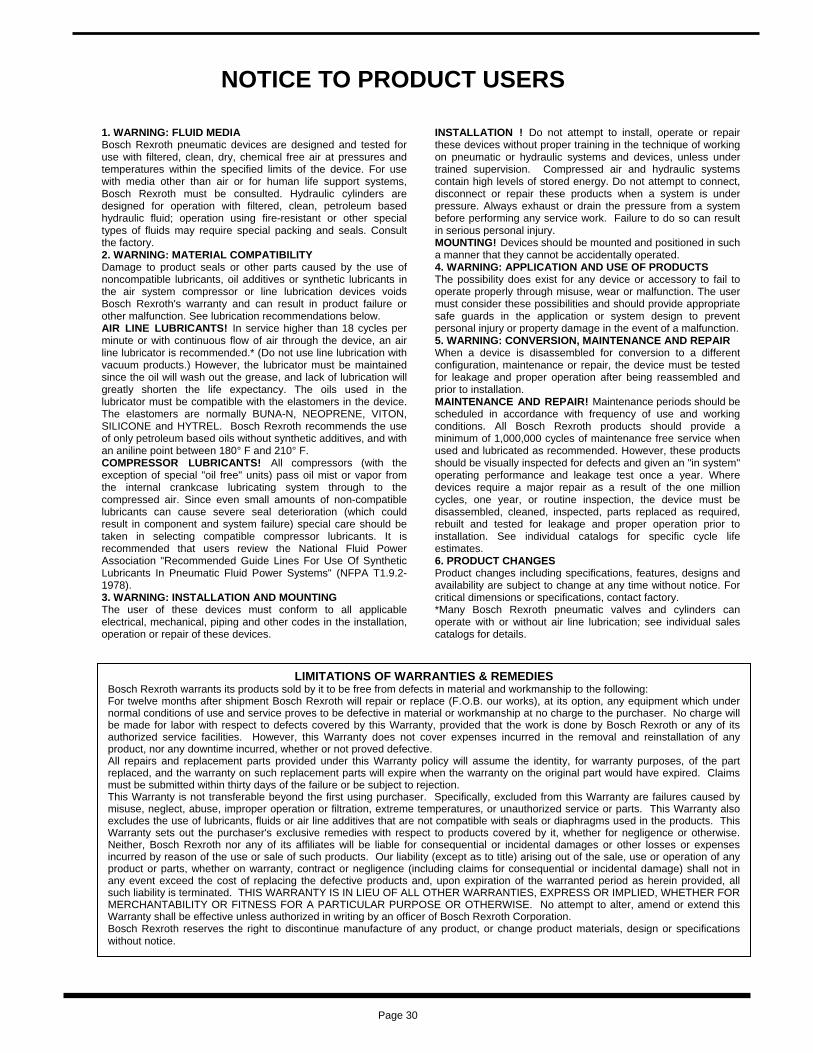
NOTICE TO PRODUCT USERS
Page 30
1. WARNING: FLUID MEDIA Bosch Rexroth pneumatic devices are designed and tested for use with filtered, clean, dry, chemical free air at pressures and temperatures within the specified limits of the device. For use with media other than air or for human life support systems, Bosch Rexroth must be consulted. Hydraulic cylinders are designed for operation with filtered, clean, petroleum based hydraulic fluid; operation using fire-resistant or other special types of fluids may require special packing and seals. Consult the factory. 2. WARNING: MATERIAL COMPATIBILITY Damage to product seals or other parts caused by the use of noncompatible lubricants, oil additives or synthetic lubricants in the air system compressor or line lubrication devices voids Bosch Rexroth's warranty and can result in product failure or other malfunction. See lubrication recommendations below. AIR LINE LUBRICANTS! In service higher than 18 cycles per minute or with continuous flow of air through the device, an air line lubricator is recommended.* (Do not use line lubrication with vacuum products.) However, the lubricator must be maintained since the oil will wash out the grease, and lack of lubrication will greatly shorten the life expectancy. The oils used in the lubricator must be compatible with the elastomers in the device. The elastomers are normally BUNA-N, NEOPRENE, VITON, SILICONE and HYTREL. Bosch Rexroth recommends the use of only petroleum based oils without synthetic additives, and with an aniline point between 180° F and 210° F. COMPRESSOR LUBRICANTS! All compressors (with the exception of special "oil free" units) pass oil mist or vapor from the internal crankcase lubricating system through to the compressed air. Since even small amounts of non-compatible lubricants can cause severe seal deterioration (which could result in component and system failure) special care should be taken in selecting compatible compressor lubricants. It is recommended that users review the National Fluid Power Association "Recommended Guide Lines For Use Of Synthetic Lubricants In Pneumatic Fluid Power Systems" (NFPA T1.9.2-1978). 3. WARNING: INSTALLATION AND MOUNTING The user of these devices must conform to all applicable electrical, mechanical, piping and other codes in the installation, operation or repair of these devices.
INSTALLATION ! Do not attempt to install, operate or repair these devices without proper training in the technique of working on pneumatic or hydraulic systems and devices, unless under trained supervision. Compressed air and hydraulic systems contain high levels of stored energy. Do not attempt to connect, disconnect or repair these products when a system is under pressure. Always exhaust or drain the pressure from a system before performing any service work. Failure to do so can result in serious personal injury. MOUNTING! Devices should be mounted and positioned in such a manner that they cannot be accidentally operated. 4. WARNING: APPLICATION AND USE OF PRODUCTS The possibility does exist for any device or accessory to fail to operate properly through misuse, wear or malfunction. The user must consider these possibilities and should provide appropriate safe guards in the application or system design to prevent personal injury or property damage in the event of a malfunction. 5. WARNING: CONVERSION, MAINTENANCE AND REPAIR When a device is disassembled for conversion to a different configuration, maintenance or repair, the device must be tested for leakage and proper operation after being reassembled and prior to installation. MAINTENANCE AND REPAIR! Maintenance periods should be scheduled in accordance with frequency of use and working conditions. All Bosch Rexroth products should provide a minimum of 1,000,000 cycles of maintenance free service when used and lubricated as recommended. However, these products should be visually inspected for defects and given an "in system" operating performance and leakage test once a year. Where devices require a major repair as a result of the one million cycles, one year, or routine inspection, the device must be disassembled, cleaned, inspected, parts replaced as required, rebuilt and tested for leakage and proper operation prior to installation. See individual catalogs for specific cycle life estimates. 6. PRODUCT CHANGES Product changes including specifications, features, designs and availability are subject to change at any time without notice. For critical dimensions or specifications, contact factory. *Many Bosch Rexroth pneumatic valves and cylinders can operate with or without air line lubrication; see individual sales catalogs for details.
LIMITATIONS OF WARRANTIES & REMEDIES Bosch Rexroth warrants its products sold by it to be free from defects in material and workmanship to the following: For twelve months after shipment Bosch Rexroth will repair or replace (F.O.B. our works), at its option, any equipment which under normal conditions of use and service proves to be defective in material or workmanship at no charge to the purchaser. No charge will be made for labor with respect to defects covered by this Warranty, provided that the work is done by Bosch Rexroth or any of its authorized service facilities. However, this Warranty does not cover expenses incurred in the removal and reinstallation of any product, nor any downtime incurred, whether or not proved defective. All repairs and replacement parts provided under this Warranty policy will assume the identity, for warranty purposes, of the part replaced, and the warranty on such replacement parts will expire when the warranty on the original part would have expired. Claims must be submitted within thirty days of the failure or be subject to rejection. This Warranty is not transferable beyond the first using purchaser. Specifically, excluded from this Warranty are failures caused by misuse, neglect, abuse, improper operation or filtration, extreme temperatures, or unauthorized service or parts. This Warranty also excludes the use of lubricants, fluids or air line additives that are not compatible with seals or diaphragms used in the products. This Warranty sets out the purchaser's exclusive remedies with respect to products covered by it, whether for negligence or otherwise. Neither, Bosch Rexroth nor any of its affiliates will be liable for consequential or incidental damages or other losses or expenses incurred by reason of the use or sale of such products. Our liability (except as to title) arising out of the sale, use or operation of any product or parts, whether on warranty, contract or negligence (including claims for consequential or incidental damage) shall not in any event exceed the cost of replacing the defective products and, upon expiration of the warranted period as herein provided, all such liability is terminated. THIS WARRANTY IS IN LIEU OF ALL OTHER WARRANTIES, EXPRESS OR IMPLIED, WHETHER FOR MERCHANTABILITY OR FITNESS FOR A PARTICULAR PURPOSE OR OTHERWISE. No attempt to alter, amend or extend this Warranty shall be effective unless authorized in writing by an officer of Bosch Rexroth Corporation. Bosch Rexroth reserves the right to discontinue manufacture of any product, or change product materials, design or specifications without notice.

Bosch Rexroth Corporation Pneumatics 1953 Mercer Road Lexington, KY 40511-1021 Telephone (859) 254-8031 Facsimile (859) 254-4188 [email protected] www.boschrexroth-us.com/brp
International offices: Asia: China Russia India Singapore Japan South Korea Malaysia Australia Europe: Austria Netherlands Belgium Norway Bulgaria Poland Czech Republic Portugal Denmark Romania Finland Slovakia France Spain Germany Sweden Greece Switzerland Hungary Turkey Italy Ukraine United Kingdom North America: Canada United States Mexico South America: Argentina Venezuela Brazil
Factory Automation Regional sales offices: Central Bosch Rexroth Corporation 5150 Prairie Stone Parkway Hoffman Estates, IL 60192-3707 Telephone (847) 645-3600 Facsimile (847) 645-0804 Great Lakes Bosch Rexroth Corporation 2730 Research Drive Rochester Hills, MI 48309 Telephone (248) 393-3330 Facsimile (248) 393-2893 Northeast Bosch Rexroth Corporation 99 Rainbow Road East Granby, CT 06026-0000 Telephone (860) 844-8377 Facsimile (860) 844-8595 Bosch Rexroth Corporation 2315 City Line Road Bethlehem, PA 18017-2131 Telephone (610) 694-8300 Facsimile (610) 694-8467 Southeast Bosch Rexroth Corporation 14001 South Lake Drive Charlotte, NC 28273-5544 Telephone (704) 583-4338 Facsimile (704) 583-0523 West Bosch Rexroth Corporation 11 Goddard Irvine, CA 92618-4600 Telephone (949) 450-2777 Facsimile (949) 450-2790
North American offices: Bosch Rexroth Corporation Corporate Headquarters 5150 Prairie Stone Parkway Hoffman Estates, IL 60192-3707 Telephone (847) 645-3600 Facsimile (847) 645-0804 Bosch Rexroth Corporation Industrial Hydraulics 2315 City Line Road Bethlehem, PA 18017-2131 Telephone (610) 694-8300 Facsimile (610) 694-8467 Bosch Rexroth Corporation Electric Drives and Controls 5150 Prairie Stone Parkway Hoffman Estates, IL 60192-3707 Telephone (847) 645-3600 Facsimile (847) 645-6201 Bosch Rexroth Corporation Linear Motion and Assembly Technologies 816 E. Third Street Buchanan, MI 49107 Telephone (269) 695-0151 Facsimile (269) 695-5363 14001 South Lakes Drive Charlotte, NC 28273 Telephone (800) 438-5983 Facsimile (704) 583-0523 Bosch Rexroth Corporation Mobile Hydraulics 145 Southchase Boulevard Fountain Inn, SC 29644-9018 Telephone (864)967-2777 Facsimile (864)962-5338
Bosch Rexroth Canada 3426 Mainway Drive Burlington, Ontario L7M 1A8 Telephone (905) 335-5511 Facsimile (905) 335-4184 www.boschrexroth.ca Bosch Rexroth, S.A. de C.V. Calle Neptuno # 72 Unidad Industrial Vallejo CP 07700 Mexico, D.F. Telephone (555) 754-1711 Facsimile (555) 752-5943 Further contacts: www.boschrexroth.com/addresses
The data specified herein only serves to describe the product. No statements concerning a certain condition or suitability for a certain application can be derived from our information. The given information does not release the user from obligation of own judgment and verification. It must be remembered that our products are subject to a natural process of wear and aging. ©This document, as well as the data, specifications and other information set forth in it, are the exclusive property of Bosch Rexroth Corp. Without their con- sent it may not be reproduced or given to third parties.
Printed in the United States SM-800.40
(Supercedes B4-72.03) December 2008 ©2008 Bosch Rexroth Corporation