small and medium deployments switch-control … and medium deployments switch-control 3.2.2-3 ......
TRANSCRIPT

®
PlexxiHCN™PlexxiGettingStartedGuide
SmallandMediumDeploymentsSwitch-Control3.2.2-3.3.0andConnect2.4.0-2.5.0
DocumentV1December8,2017
® 100InnovativeWay-Suite3322Nashua,NH03062Tel.+1.888.630.PLEX(7539)www.plexxi.com

2 PlexxiGettingStartedGuide:SmallandMediumDeployments
LegalNoticesThe information contained herein is subject to change without notice. Plexxi®, the Plexxi logo, and LightRail® are registered trademarks, and Plexxi HCN™, Plexxi Control™ and Plexxi Connect™ are trademarks of Plexxi, Inc. in the United States and other countries. Other product or service name may be trademarks or service marks of others. No part of this documentation may be reproduced in any form or by any means or used to make any derivative work (such as translation, transformation, or adaptation) without written permission from Plexxi, Inc. Plexxi, Inc. reserves all rights of copyright in this documentation. PLEXXI, INC. PROVIDES THIS DOCUMENTATION “AS IS,” WITHOUT WARRANTY, TERM, OR CONDITION OF ANY KIND, EITHER IMPLIED OR EXPRESSED, INCLUDING, BUT NOT LIMITED TO, THE IMPLIED WARRANTIES, TERMS, OR CONDITIONS OF MERCHANTABILITY, SATISFACTORY QUALITY, NON-INFRINGEMENT AND FITNESS FOR A PARTICULAR PURPOSE. Plexxi, Inc. reserves the right to make changes to equipment design or program components described in this documentation, as progress in engineering, manufacturing methods, or other circumstances may warrant. No responsibility is assumed for the use of Plexxi, Inc. software or hardware, all rights, obligations and remedies related to which are as set forth in the applicable sales and license agreements.
Plexxi, Inc. 100 Innovative Way - Suite 3322 Nashua, NH 03062 Tel: +1.888.630.PLEX (7539) www.plexxi.com
Published November 8, 2017 Printed in United States of America. Copyright © 2017 Plexxi, Inc. All rights reserved.
The Plexxi Switch system is classified as a class 1 telecommunications laser product employing embedded class 1 lasers and complies with the following:
THIS PRODUCT COMPLIES WITH FDA RULE 21 CFR SUBCHAPTER J IN EFFECT AT DATE OF MANUFACTURE. PRODUCT COMPLIES WITH 21 CFR 1040.10 AND 1040.11
PRODUIT CONFORME SELON LE SOUS CHAPITRE J DU DOCUMENT FDA RÈGLE 21 CFR EN VIGUEUR LORS DE LA DATE DE FABRICATION. PRODUIT CONFORME SELON 21CFR 1040.10 ET 1040.11.
Electrotechnical Commission (IEC) 60825-1, 60825-2
This product is classified as a: CLASS 1 LASER PRODUCT
APPAREIL À LASER DE CLASSE 1
This unit is intended to be installed in a Restricted Access Location only with access only by trained personnel.
Warning: The primary hazards of exposure to invisible laser radiation from an optical fiber communications system are:
ï Damage to the eye by viewing an unterminated optical fiber or fiber optic connector. ï Damage to the eye from invisible laser radiation from viewing a cut fiber or a broken fiber.
Never attempt to view optical connectors that may be emitting laser energy and always avoid possible exposure to invisible optical laser radiation. Using optical fiber scopes or magnifying lenses may increase the possibility for an eye hazard. It is recommended that you use an optical power meter to determine if there is optical laser radiation present or use a remote video display inspection tool to inspect connectors.

PlexxiGettingStartedGuide:SmallandMediumDeployments 3
TableofContents
LegalNotices......................................................................................................................................2
ContactingPlexxiSupport..................................................................................................................4
1 InstallationandCablingAssumptions...........................................................................................5
2 CreatingaDirectConnectNetwork...............................................................................................6DirectConnecting2,2S,2Pand2SPSwitches..................................................................................................6DirectConnecting2eand3eqSwitches(2Switches)....................................................................................7DirectConnecting2eand3eqSwitches(4Switches)....................................................................................8
3 CreatingaPSINetwork.................................................................................................................9ConnectingSwitches2eand3eqtothePSI.......................................................................................................9LoopingBackUnusedPSIPorts............................................................................................................................9ConnectingMultiplePSIDevicestoExpandtheFabric.................................................................................9PSINetworkExample............................................................................................................................................10
4 L1Validation..............................................................................................................................11Runningpx-setup....................................................................................................................................................11
5 DeployingaPlexxiControlVMusingOVA...................................................................................12Supported..................................................................................................................................................................12VMRequirements...................................................................................................................................................12DownloadingtheOVAFile...................................................................................................................................12DeployingthePlexxiControlVM.......................................................................................................................12
6 DeployingaPlexxiConnectVMusingOVA.................................................................................14Supported..................................................................................................................................................................14VMRequirements...................................................................................................................................................14DownloadingtheOVAFile...................................................................................................................................14DeployingthePlexxiConnectVM......................................................................................................................14
7 CreatingPackConfigurationsinPlexxiConnect..........................................................................16ConfiguringthePlexxiControlConfiguration...............................................................................................16ConfiguringVMwarevSphereConfigurations..............................................................................................16RegisteringthevSpherePluginwithVMware..............................................................................................16AddingaConfiguringNutanixPrismConfigurations..................................................................................17
8 Configuring3rd-PartyMLAG/LAGUplinkstoPlexxiSwitches.......................................................18NutanixMLAG/LAG................................................................................................................................................18MLAG/LAGwithCisco............................................................................................................................................21MLAG/LAGwithArista..........................................................................................................................................24

4 PlexxiGettingStartedGuide:SmallandMediumDeployments
ContactingPlexxiSupportPlexxi Support services are available to answer questions and to make sure your software and hardware operate properly.
Contact Plexxi Support at:
1.888.415.9809 (US/Canada toll-free)
+1 603-782-0702 (US/International)
http://support.plexxi.com

PlexxiGettingStartedGuide:SmallandMediumDeployments 5
1 InstallationandCablingAssumptions
This procedure assumes the following:
• You are knowledgeable in network administration, cable management, optical cable cleaning and handling.
• The switches have been unpacked and installed in racks, power cables installed, and rack power is on. Refer to the appropriate hardware installation document for each Plexxi switch.
• You have all transceivers and cables needed:
o to connect Plexxi switches to each other, creating the Plexxi fabric.
o to connect uplink ports to non-Plexxi switches.
o For management cabling, connect the Plexxi MGMT port to an external out-of-band Layer 2 switch.
• The latest Plexxi Switch software is installed on the Plexxi switches.
• You have an internet connection to download installers, etc.
• You have a console connection to a switch in the fabric.
• Your network architecture and connections has been designed and you have access to all port, cabling and configuration information as needed, including IP addresses of switches, controller, NTP server, DNS server, SNMP server/services, as well as time zones and host names.
• You have all usernames and passwords to be used for Plexxi Switch, Plexxi Control and Plexxi Connect software access.

6 PlexxiGettingStartedGuide:SmallandMediumDeployments
2 CreatingaDirectConnectNetwork
In a direct connect network, Plexxi switches are connected directly without the use of a PSI device (see next chapter).
Any number of Plexxi switches that contain LightRail connectors (Switches 2, 2S, 2P and 2SP) can be connected together using direct-connect; directly connected through the LightRail ports with MTP cables.
As many as seven Plexxi Switches 2e and 3eq that connect through QSFP ports can be connected together using direct connect. You should not directly connect Plexxi 3eq and 2e switches in a network if the deployment is expected to grow beyond seven switches.
You cannot directly connect Switches 2e, 3eq to Switches 2, 2S, 2P and 2SP.
DirectConnecting2,2S,2Pand2SPSwitchesFor these switches, simply connect the LightRail cables East and West to the neighbor switches. Repeat this for each switch to complete the fabric. For example:
PlexxiGettingStartedGuide:SmallandMediumDeployments 7
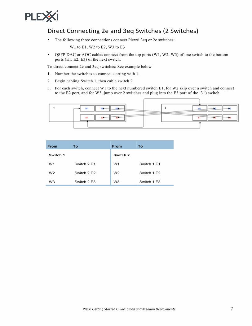
DirectConnecting2eand3eqSwitches(2Switches)• The following three connections connect Plexxi 3eq or 2e switches:
W1 to E1, W2 to E2, W3 to E3
• QSFP DAC or AOC cables connect from the top ports (W1, W2, W3) of one switch to the bottom ports (E1, E2, E3) of the next switch.
To direct connect 2e and 3eq switches: See example below
1. Number the switches to connect starting with 1.
2. Begin cabling Switch 1, then cable switch 2.
3. For each switch, connect W1 to the next numbered switch E1, for W2 skip over a switch and connect to the E2 port, and for W3, jump over 2 switches and plug into the E3 port of the ‘3rd) switch.
From To From To
Switch 1 Switch 2
W1 Switch 2 E1 W1 Switch 1 E1
W2 Switch 2 E2 W2 Switch 1 E2
W3 Switch 2 E3 W3 Switch 1 E3
8 PlexxiGettingStartedGuide:SmallandMediumDeployments
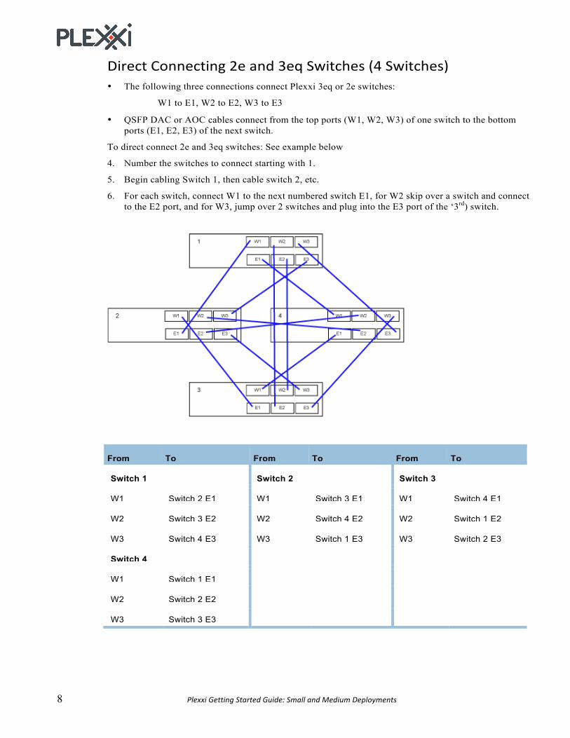
DirectConnecting2eand3eqSwitches(4Switches)• The following three connections connect Plexxi 3eq or 2e switches:
W1 to E1, W2 to E2, W3 to E3
• QSFP DAC or AOC cables connect from the top ports (W1, W2, W3) of one switch to the bottom ports (E1, E2, E3) of the next switch.
To direct connect 2e and 3eq switches: See example below
4. Number the switches to connect starting with 1.
5. Begin cabling Switch 1, then cable switch 2, etc.
6. For each switch, connect W1 to the next numbered switch E1, for W2 skip over a switch and connect to the E2 port, and for W3, jump over 2 switches and plug into the E3 port of the ‘3rd) switch.
From To From To From To
Switch 1 Switch 2 Switch 3
W1 Switch 2 E1 W1 Switch 3 E1 W1 Switch 4 E1
W2 Switch 3 E2 W2 Switch 4 E2 W2 Switch 1 E2
W3 Switch 4 E3 W3 Switch 1 E3 W3 Switch 2 E3
Switch 4
W1 Switch 1 E1
W2 Switch 2 E2
W3 Switch 3 E3

PlexxiGettingStartedGuide:SmallandMediumDeployments 9
3 CreatingaPSINetwork
The Plexxi Pod Switch Interconnect (PSI) device, illustrated below, is designed to accommodate the following Plexxi network installation scenarios:
• Connecting more than seven Plexxi 2e and 3eq switches
• Creating a Plexxi network of any size that contains both Plexxi switches with LightRail connectors (2P, 2SP) and switches without (2e and 3eq).
You can create a network of four or more Plexxi switches by connecting switches to a Plexxi Pod Switch Interconnect (PSI) device, shown here:
Using a PSI, you can create a network topology that includes any Plexxi switch.
ConnectingSwitches2eand3eqtothePSIConnect Plexxi PSI Interconnect LightRail ports to Plexxi Switch QSFP ports following the West-to-East convention. Plug the 24-fiber connector into the Plexxi PSI Interconnect port and the three 12-fiber connectors of the MTP cable to transceivers installed in the QSFP ports on the Plexxi Switch.
You need to match the label number (1, 2, and 3) on the 12-fiber side of the MTP connectors with a specific port number on Plexxi Switch. Connect to the appropriate QSFP port in the appropriate direction, West or East.
LoopingBackUnusedPSIPortsYou must loopback any unused PSI ports, including the extender ports, using 10-inch 24F MTP cables. The next section illustrates looped back ports in 4-switch PSI configuration.
ConnectingMultiplePSIDevicestoExpandtheFabricPSI devices can be connected to scale out the Plexxi fabric. Three 24-fiber MTP cables are used to connect to a PSI device to the next (East) PSI device, and an additional three cables are used to connect to the previous (West) PSI device.

10 PlexxiGettingStartedGuide:SmallandMediumDeployments
PSINetworkExampleThe following illustration shows a network topology that includes four Plexxi 3eq (or 2e switches) connected through a Plexxi PSI. In this case, we assume that the network is planned to grow beyond 7 switches, therefore advising the use of a PSI device. If a network will not exceed 7 switches, you can use direct connect.
As shown, all unused PSI ports are looped back using loopback cables.
Note: The QSFP ports in the diagram include a label indicating direction: W1 through W3 and E1 through E3. These labels are informational and are not found on the Plexxi Switch chassis.

PlexxiGettingStartedGuide:SmallandMediumDeployments 11
4 L1Validation
Test all Plexxi fabric connections using the following Plexxi commands: px-topology ring uplink status
px-topology ring peering status
px-topology ring confluent-ring-lags
Runningpx-setuppx-setup is a Plexxi utility that simplifies Plexxi switch setup by eliminating the need to edit configuration files on the Plexxi Switch. The utility queries administrators for information, then configures the IP or hostname of the Plexxi Control software, time zone, network address, default gateway, SNMP management, and several network services, including NTP and DNS.
The px-setup commands require root/sudo privilege to modify core services. To setup all switches and all network characteristics for a new install, use px-setup without arguments:
$ sudo px-setup
Note: px-setup recommends UTC as default for Time Zone and Plexxi recommends that you use UTC as Time Zone for Plexxi Switch and Plexxi Control.
IMPORTANT: Plexxi strongly recommends that Plexxi Connect, Plexxi Control and Plexxi Switches all be connected to a reliable NTP service.
Help is also available through the manpage: $ man px-setup

12 PlexxiGettingStartedGuide:SmallandMediumDeployments
5 DeployingaPlexxiControlVMusingOVA
Plexxi Control can be installed from an OVA file designed for deployment on virtual hosts. In this section, you will use OVA from a VMware vSphere Web Client to deploy a new VMware VM to host the Plexxi Control software.
Supported• Hypervisors: VMware ESXi or Nutanix AHV
• Operating system: The installation deploys a Linux CentOS VM
VMRequirementsThe Plexxi Control virtual machine (VM) must meet the following minimum requirements:
• 4 CPUs
• 8 GB RAM
• 200 GB disk space
DownloadingtheOVAFile1. Determine the version of Plexxi Control software to install.
IMPORTANT: Refer to the Plexxi Compatibility Matrix for information on compatibility between Plexxi Control and Plexxi Switch software.
2. Download the OVA file, plexxicontrol-version-date.ova, from https://software.plexxi.com in Control > releases > version.
DeployingthePlexxiControlVMDeploy the Plexxi Control VM using OVA as follows:
1. Save the downloaded OVA file in a location for the OVA deployment.
2. Open the VMware vSphere Web Client.
3. If you are logging into vSphere 6.0 or older, you may be prompted to install the Client Integration Plug-in in your web browser. If prompted, you must install the Client Integration Plug-in to enable OVA deployment from your web browser.
4. Select a VCenter server or a specific hypervisor.
5. Select Deploy OVF Template from the Actions menu or by right-clicking the hypervisor and selecting Deploy OVF Template.
6. In Select source, browse for the plexxicontrol- version-date.ova file either locally or remotely as saved above. Click Next.
7. Verify the Plexxi Control OVF template details. Click Next.
8. Read the end user license agreement and click Accept to accept the license agreement. Click Next.
9. Enter a name and select a folder for the Plexxi Control VM. Click Next.
10. In Select storage, select the virtual disk format, VM Storage Policy (Datastore Default) and select the datastore for the VM. Click Next.
11. In Setup Networks, select the source network (vSwitch or port group). Click Next.

PlexxiGettingStartedGuide:SmallandMediumDeployments 13
12. In Customize template, enter a VM hostname and set up either static IP or DHCP.
In A) Network – General Settings, configure:
• The Hostname for the Plexxi Control VM host; for example, plexxi-control.
• The Domain Name on the Plexxi Control VM resides. This should be a valid DNS domain name, or if the network/deployment environment does not have a domain, you can use "localdomain" as the domain name.
• Time Servers (NTP): IP addresses or hostnames of the primary and secondary Network Time Servers (NTP) that Plexxi Control will use to synchronize its’ internal clock. It is STRONGLY recommended to use NTP servers to ensure that all elements of the Plexxi system have the most accurate time & date settings. Note that when using DHCP, the NTP server information will not need to be provided. You should confirm that your DHCP server is properly configured to provide NTP server(s) when fulfilling DHCP requests.
In B) Network – Static IP Settings, configure:
• For static IP, enter the IP Address, Network Mask, and Default Gateway as needed for your environment.
• DNS Servers: For static IP, provide the IP address of the primary and secondary DNS servers that Plexxi Control will use to resolve hostnames. When using DHCP, DNS server information is not needed.
• For DHCP, select the DHCP check box and leave the IP address as 0.0.0.0.
IMPORTANT: If you use DHCP, you must reserve an IP address on the DHCP server.
In C) Network – DHCP Settings, configure:
• Use DHCP: Check this option if DHCP is used.
13. When finished, click Next.
14. In Ready to complete, verify the entered configuration settings. Click Finish.
15. You can monitor the OVA Install progress in the Recent Tasks window:
16. When finished, in vSphere, locate and Power On the new VM.
17. Verify the installation. In a Web browser, enter the Plexxi Control URL. The URL format is:
https://<hostname>:8443/PlexxiUI/
IMPORTANT: When connecting to Plexxi Control on port 8443, you must use the server's FQDN (Fully Qualified Domain Name).
Log into Plexxi Control as administrator using the default credentials:
Username: admin
Password: plexxi
Verify that the Plexxi Control UI opens successfully.
18. Plexxi recommends that, while logged into the Plexxi Control UI as administrator, you change the Plexxi Control password to a secure password.
19. Plexxi recommends that you connect to the new VM and change the default Linux passwords for the root and plexxi user accounts.
20. Optionally, type <ctrl>-d to logout from the Linux session.
The Plexxi Control installation is complete.

14 PlexxiGettingStartedGuide:SmallandMediumDeployments
6 DeployingaPlexxiConnectVMusingOVA
Plexxi Connect can be installed from an OVA file designed for deployment on virtual hosts. In this section, you will use OVA from a VMware vSphere Web Client to deploy a new VMware VM to host the Plexxi Connect software.
Supported• Hypervisors: VMware ESXi or Nutanix AHV
• Operating system: The installation deploys a Linux CentOS VM
VMRequirementsThe Plexxi Control virtual machine (VM) must meet the following minimum requirements:
• 2 CPUs
• 8 GB RAM
• 50 GB disk space
DownloadingtheOVAFile1. Determine the version of Plexxi Connect software to install.
IMPORTANT: You can refer to the Plexxi Compatibility Matrix for software compatibility.
2. Download the OVA installer file, PlexxiConnect-version-###.ova, from https://software.plexxi.com in Connect > releases > version.
DeployingthePlexxiConnectVMDeploy a Plexxi Connect VM using OVA as follows:
1. Connect and log into the VMware vSphere Web Client.
2. Select a vSphere server or a specific ESX host.
3. Select Deploy OVF Template from the Actions menu or by right-clicking the hypervisor and selecting Deploy OVF Template. The OVF window opens.
4. In Select source, browse for the PlexxiConnect-version-###.ova file to download. Click Next.
5. In Review details, verify the Plexxi Connect OVF template details. Click Next.
6. Read the license agreement and click Accept to accept the agreement. Click Next.
7. In Select name and folder, enter a name and location for the Plexxi Connect VM folder. Click Next.
8. In Select storage, select the virtual disk format, VM Storage Policy (Datastore Default) and select the datastore for the VM. Click Next.
9. In Setup networks, select the source and destination networks. Click Next.
21. In Customize template, enter a VM hostname and set up either static IP or DHCP.
In A) Network – General Settings, configure:
• The Hostname for the Plexxi Control VM host; for example, plexxi-control.
• The Domain Name on the Plexxi Control VM resides. This should be a valid DNS domain name, or if the network/deployment environment does not have a domain, you can use "localdomain" as the domain name.

PlexxiGettingStartedGuide:SmallandMediumDeployments 15
• Time Servers (NTP): IP addresses or hostnames of the primary and secondary Network Time Servers (NTP) that Plexxi Control will use to synchronize its’ internal clock. It is STRONGLY recommended to use NTP servers to ensure that all elements of the Plexxi system have the most accurate time & date settings. Note that when using DHCP, the NTP server information will not need to be provided. You should confirm that your DHCP server is properly configured to provide NTP server(s) when fulfilling DHCP requests.
In B) Network – Static IP Settings, configure:
• For static IP, enter the IP Address, Network Mask, and Default Gateway as needed for your environment.
• DNS Servers: For static IP, provide the IP address of the primary and secondary DNS servers that Plexxi Control will use to resolve hostnames. When using DHCP, DNS server information is not needed.
• For DHCP, select the DHCP check box and leave the IP address as 0.0.0.0.
IMPORTANT: If you use DHCP, you must reserve an IP address on the DHCP server.
In C) Network – DHCP Settings, configure:
• Use DHCP: Check this option if DHCP is used.
10. When finished, click Next.
11. In Ready to complete, verify the entered configuration settings. Click Finish.
12. You can monitor the OVA Install progress in the Recent Tasks window:
13. When finished, in vSphere, locate and Power On the new VM.
14. Verify the installation. In a Web browser, enter the URL and log into the UI. The URL format is:
PlexxiConnectUI:http://<IP>
http://<hostname>
PlexxiPrismUI:http://<IP>/prism
http://<hostname>/prism
Log in as administrator using the default credentials:
Username: admin
Password: plexxi
Verify that the UI opens successfully.
15. Plexxi recommends that you change the Plexxi Connect admin user password to a secure password as described in the Plexxi Connect UI online help.
16. While logged into the Plexxi Connect UI as administrator, you must create (add):
• One Plexxi Control pack configuration.
• VMware vSphere and/or Nutanix Prism pack configurations as needed for your environment.
While in the Plexxi Connect UI, refer to the Plexxi Connect Help for information on adding pack configurations.
17. Plexxi recommends that you connect to the new VM and change the default Linux password for the admin user account.
18. Optionally, type <ctrl>-d to logout from the Linux session.
The Plexxi Connect installation is complete.

16 PlexxiGettingStartedGuide:SmallandMediumDeployments
7 CreatingPackConfigurationsinPlexxiConnect
Refer to the following documentation for further information:
• Plexxi Connect User Guide
• Plexxi Connect Online Help is available while logged into the Plexxi Connect UI
ConfiguringthePlexxiControlConfigurationConfigure Plexxi Connect access to Plexxi Control by adding a single Plexxi Control configuration instance as follows:
1. Open and log into the Plexxi Connect UI.
2. In Plexxi Connect, select Configuration > Packs > Plexxi Control , then click the Add button. The Plexxi Control Configuration window opens.
1. In the Plexxi Control configuration window, configure the parameters as needed.
2. (Recommended) Click Validate to validate the configuration and its connections. A Validation Successful popup should be returned.
3. Click Apply to save the configuration or Cancel to exit without saving.
ConfiguringVMwarevSphereConfigurationsConfigure Plexxi Connect access to VMware vSphere by adding one or more VMware vSphere configurations using the Plexxi Connect UI as follows:
1. Open and login to the Plexxi Connect UI.
2. InPlexxiConnect,selectConfiguration>Packs>VMwarevSphere,thenclickAdd.
3. In the VMware vSphere configuration window, configure the parameters as needed.
4. (Recommended) Click Validate to validate the configuration and its connections. A Validation Successful popup should be returned.
5. Click Apply to save the configuration or Cancel to exit without saving.
6. Repeat the steps above to add additional VMware vSphere configurations. As many as ten vSphere configurations can be added.
RegisteringthevSpherePluginwithVMwareBefore you can use the vSphere Plugin, in the Plexxi Connect UI, you must create one vSphere configuration as described above, then register the vSphere Plugin with VMware.
Note:WhenthePlexxivSpherepluginisregistered,bi-directionalcommunicationmustbeavailablebetweenPlexxiConnectandVMwarevSphere(i.e.PlexxiConnectmustbeabletoreachvSphere,andvSpheremustbeabletoreachPlexxiConnect).Ifthiscommunicationisnotavailable,thepluginregistrationwillfail,howeveritwillbereportedassuccessfullyregistered.
ToregisterthevSpherePluginwithVMware:
1.InPlexxiConnect,selectConfiguration>Packs>VMwarevSphere.
2.UnderActionsonthelinefortheconfiguration,clicktheRegistervSphereicon.
3.Atthefollowingprompt,clickOKtoregisterthepluginwithVMwareorCanceltoexit.
Whentheregistrationcompletes,asuccessnotificationappears.

PlexxiGettingStartedGuide:SmallandMediumDeployments 17
AddingaConfiguringNutanixPrismConfigurationsIf needed for Nutanix Prism, configure Plexxi Connect access to Nutanix Prism by adding one or more Prism configurations using the Plexxi Connect UI as follows:
1. Open the Plexxi Connect UI.
2. InPlexxiConnect,selectConfiguration>Packs>NutanixPrism,thenclickAdd.
3. In the Nutanix Prism configuration window, configure the parameters as needed.
4. (Recommended) Click Validate to validate the configuration and its connections. A Validation Successful popup should be returned.
5. Click Apply to save the configuration or Cancel to exit without saving.
6. Repeat the steps above to add additional Nutanix Prism configurations. As many as ten Nutanix Prism configurations can be added.

18 PlexxiGettingStartedGuide:SmallandMediumDeployments
8 Configuring3rd-PartyMLAG/LAGUplinkstoPlexxiSwitches
NutanixMLAG/LAGFor Nutanix AHV environments, the following example illustration shows a two-port LAG between an Open vSwitch (OVS) and two Plexxi switches.
The following sets up OVS port br0: ovs-vsctl set port br0-up lacp=active
ovs-vsctl set port br0-up other_config:lacp-time=fast
ovs-vsctl set port br0-up bond_mode=balance-tcp
In the Plexxi Control UI, create an MLAG on the Plexxi switch. The following Plexxi Control screenshot shows Plexxi Switch 3eq ports 15 and 16 configured to connect to the OVS eth2 and eth3 ports.

PlexxiGettingStartedGuide:SmallandMediumDeployments 19
The following command shows OVS port br0 port bond status: [root@NTNX-17SM6C010138-A ~]# ovs-appctl bond/show br0-up
---- br0-up ----
bond_mode: balance-tcp
bond may use recirculation: yes, Recirc-ID : 1
bond-hash-basis: 0
updelay: 0 ms
downdelay: 0 ms
next rebalance: 905 ms
lacp_status: negotiated
active slave mac: 00:e0:ed:57:40:cb(eth3)
slave eth0: disabled
may_enable: false
slave eth1: disabled
may_enable: false
slave eth2: enabled
may_enable: true
slave eth3: enabled
active slave
may_enable: true
slave eth4: disabled
may_enable: false
slave eth5: disabled
may_enable: false
[root@NTNX-17SM6C010138-A ~]#
The following commands show the LACP status and configuration information for the two sample Plexxi switches:
switch-a1-4# show lacp
Interface xp15 is up
Part of LAG lag1025 (balance-tcp)
LAG ID: [ (8000, e0-39-d7-4a-f0-5a, 1, E, 0), (FFFE, c-c4-7a-9c-a6-fe, 1, 2, FFFF) ]
LACP Info Local (Actor) Neighbor (Partner)
------------------ ------------------------ ------------------------
LACP Status: forwarding forwarding
System Priority: 32768 65534
MAC Address: e0-39-d7-4a-f0-5a c-c4-7a-9c-a6-fe
System Identifier: 0x8000,e0-39-d7-4a-f0-5a 0xFFFE,c-c4-7a-9c-a6-fe
Operational Key: 1 1
Port Priority: 0 65535
Port Identifier: 0x0,0xE 0xFFFF,0x2
LACP_Activity: active active
LACP_Timeout: fast interval fast interval

20 PlexxiGettingStartedGuide:SmallandMediumDeployments
Synchronization: IN_SYNC IN_SYNC
Collecting: true true
Distributing: true true
Actor Oper State: (Ac-1:To-1:Ag-1:Sy-1:Co-1:Di-1:De-0:Ex-0)
Partner Oper State: (Ac-1:To-1:Ag-1:Sy-1:Co-1:Di-1:De-0:Ex-0)
switch-a1-4#
switch-a1-2# show lacp
Interface xp16 is up
Part of LAG lag1025 (balance-tcp)
LAG ID: [ (8000, e0-39-d7-4a-f0-5a, 1, F, 0), (FFFE, c-c4-7a-9c-a6-fe, 1, 1, FFFF) ]
LACP Info Local (Actor) Neighbor (Partner)
------------------ ------------------------ ------------------------
LACP Status: forwarding forwarding
System Priority: 32768 65534
MAC Address: e0-39-d7-4a-f0-5a c-c4-7a-9c-a6-fe
System Identifier: 0x8000,e0-39-d7-4a-f0-5a 0xFFFE,c-c4-7a-9c-a6-fe
Operational Key: 1 1
Port Priority: 0 65535
Port Identifier: 0x0,0xF 0xFFFF,0x1
LACP_Activity: active active
LACP_Timeout: fast interval fast interval
Synchronization: IN_SYNC IN_SYNC
Collecting: true true
Distributing: true true
Actor Oper State: (Ac-1:To-1:Ag-1:Sy-1:Co-1:Di-1:De-0:Ex-0)
Partner Oper State: (Ac-1:To-1:Ag-1:Sy-1:Co-1:Di-1:De-0:Ex-0)
switch-a1-2#

PlexxiGettingStartedGuide:SmallandMediumDeployments 21
MLAG/LAGwithCiscoThe following is a sample configuration showing how to configure a vPC (virtual Port Channel) between two Cisco Nexus 5000 series connected to two Plexxi Switches through an MLAG.
Enable LACP and vPC on both Cisco switches:
For Cisco-5k-01 feature lacp
feature vpc
For Cisco-5k-02 feature lacp
feature vpc
Configure a vPC domain on both Cisco switches:
For Cisco-5k-01 vpc domain 1
For Cisco-5k-02 vpc domain 1
Configure the peer keep-alive IP addresses:
For Cisco-5k-01 peer-keepalive destination 172.20.22.2
For Cisco-5k-02 peer-keepalive destination 172.20.22.1
Create a Port Channel for the vPC between the two Cisco 5000 series switches.
For Cisco-5k-01 interface port-channel1
switchport mode trunk
switchport trunk allowed vlan 1,21
spanning-tree port type network
speed 10000
vpc peer-link
For Cisco-5k-02 interface port-channel1
switchport mode trunk
switchport trunk allowed vlan 1,21
spanning-tree port type network
speed 10000
vpc peer-link
Configure interfaces to be members of the vPC:
For Cisco-5k-01 interface Ethernet1/19
switchport mode trunk
switchport trunk allowed vlan 1,21
channel-group 1 mode active
22 PlexxiGettingStartedGuide:SmallandMediumDeployments
interface Ethernet1/20
switchport mode trunk
switchport trunk allowed vlan 1,21
channel-group 1 mode active
For Cisco-5k-02 interface Ethernet1/19
switchport mode trunk
switchport trunk allowed vlan 1,21
channel-group 1 mode active
interface Ethernet1/20
switchport mode trunk
switchport trunk allowed vlan 1,21
channel-group 1 mode active
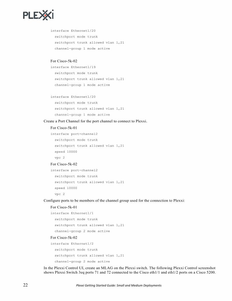
Create a Port Channel for the port channel to connect to Plexxi.
For Cisco-5k-01 interface port-channel2
switchport mode trunk
switchport trunk allowed vlan 1,21
speed 10000
vpc 2
For Cisco-5k-02 interface port-channel2
switchport mode trunk
switchport trunk allowed vlan 1,21
speed 10000
vpc 2
Configure ports to be members of the channel group used for the connection to Plexxi:
For Cisco-5k-01 interface Ethernet1/1
switchport mode trunk
switchport trunk allowed vlan 1,21
channel-group 2 mode active
For Cisco-5k-02 interface Ethernet1/2
switchport mode trunk
switchport trunk allowed vlan 1,21
channel-group 2 mode active
In the Plexxi Control UI, create an MLAG on the Plexxi switch. The following Plexxi Control screenshot shows Plexxi Switch 3eq ports 71 and 72 connected to the Cisco eth1/1 and eth1/2 ports on a Cisco 5200.

PlexxiGettingStartedGuide:SmallandMediumDeployments 23
The following Plexxi Control screenshot shows Plexxi Switch 3eq ports 71 and 72 connected to the
Cisco eth1/1 and eth1/2 ports on a Cisco 5800.

24 PlexxiGettingStartedGuide:SmallandMediumDeployments
MLAG/LAGwithAristaThis example shows a four port MLAG between two Arista 7050s and two Plexxi Switch 3EQs with fast LACP.
The following sample Plexxi Control screenshot shows Plexxi Switch 3eq QSFP port 33 connected to Arista.
Configure a port channel on AR-7050s-1A: interface Port-Channel20
switchport trunk allowed vlan 20
switchport mode trunk
mlag 20
Two interfaces with fast LACP are members of the port channel: interface Ethernet49/1
description sw-s1532s1x-p33
speed forced 40gfull
switchport mode trunk
channel-group 20 mode active

PlexxiGettingStartedGuide:SmallandMediumDeployments 25
lacp rate fast
interface Ethernet50/1
description sw-s1533s1x-p33
speed forced 40gfull
switchport mode trunk
channel-group 20 mode active
lacp rate fast
A port channel is configured on AR-7050s-2: interface Port-Channel20
switchport trunk allowed vlan 20
switchport mode trunk
mlag 20
Two interfaces are members of the port channel. Both have fast LACP enabled. interface Ethernet49/1
description sw-s1532s1x-p33
speed forced 40gfull
switchport mode trunk
channel-group 20 mode active
lacp rate fast
interface Ethernet50/1
description sw-s1533s1x-p33
speed forced 40gfull
switchport mode trunk
channel-group 20 mode active
lacp rate fast
A peer group is created between both Arista switches on AR-7050s-1: interface Port-Channel1
description ar7050s-2
switchport mode trunk
switchport trunk group mlagpeer
interface Ethernet51/1
speed forced 40gfull
channel-group 1 mode active
interface Ethernet52/1
speed forced 40gfull
channel-group 1 mode active
A peer group is created between both Arista switches on AR-7050s-2: interface Port-Channel1
description ar7050s-1
switchport mode trunk

26 PlexxiGettingStartedGuide:SmallandMediumDeployments
switchport trunk group mlagpeer
interface Ethernet51/1
speed forced 40gfull
channel-group 1 mode active
interface Ethernet52/1
speed forced 40gfull
channel-group 1 mode active