small engine series - freebee.ucoz.com · a freebee publication small engine series pratt and...
TRANSCRIPT

A FreeBee Publication
Small Engine Series
Pratt and Whitney PT6A Engine Rigging by FreeBee is licensed under a Creative Commons Attribution 3.0 International License. Page 1 of 80

A FreeBee Publication
Pratt and Whitney PT6A Engine Rigging by FreeBee is licensed under a Creative Commons Attribution 3.0 International License. Page 2 of 80

A FreeBee Publication
Typical Twin Engine Aircraft With 3 Engine Control Levers
Power Levers
Propeller Levers
Fuel Condition Levers
Engine ControlFriction Locks
Pratt and Whitney PT6A Engine Rigging by FreeBee is licensed under a Creative Commons Attribution 3.0 International License. Page 3 of 80

A FreeBee Publication
Pratt and Whitney PT6A Engine Rigging by FreeBee is licensed under a Creative Commons Attribution 3.0 International License. Page 4 of 80

A FreeBee Publication
Pratt and Whitney PT6A Engine Rigging by FreeBee is licensed under a Creative Commons Attribution 3.0 International License. Page 5 of 80
A FreeBee Publication
Pratt and Whitney PT6A Engine Rigging by FreeBee is licensed under a Creative Commons Attribution 3.0 International License. Page 6 of 80

A FreeBee Publication
Pratt and Whitney PT6A Engine Rigging by FreeBee is licensed under a Creative Commons Attribution 3.0 International License. Page 7 of 80

A FreeBee Publication
BASIC ENGINE RIGGING
Purpose:
Provide the operator with a basic approach to engine rigging .Define a logical sequence to follow when rigging the engine.It also describes the post rigging runs and adjustments required to obtain ideal cockpit lever to engine response relationships.
Use the correct maintenance manual / modification supplements for the specific engine rigging information.
Pre-Rigging Checks:
1 – Ensure cockpit levers operate freely.2 – Ensure engine cables are not damaged or worn excessively.3 – Verify that the carbon block is within dimensional limits and condition.4 – Ensure linkage is connected correctly and is in good condition.5 – Ensure beta ring runout is within limits.6 – Ensure cam box is not damaged and is in good condition.7 – Ensure minimal freeplay in engine control to cambox lever.8 – Ensure engine airframe controls are rigged prior to rigging engine.9 – Check that the beta valve moves freely.
Pratt and Whitney PT6A Engine Rigging by FreeBee is licensed under a Creative Commons Attribution 3.0 International License. Page 8 of 80

A FreeBee Publication
Speed Governors Installed on Engine
Pratt and Whitney PT6A Engine Rigging by FreeBee is licensed under a Creative Commons Attribution 3.0 International License. Page 9 of 80
A FreeBee Publication
Power Lever
Function
Gives the operator control over the fuel schedule and propeller pitch position in the Beta Range. Gives the operator control over the fuel schedule only, in Alpha Range Has 3 mechanical stops:( with a possible 4th stop as ground fine)
Full Forward - Maximum Gas Generator RPMFlight Idle - Gate - sets Flight Idle RPM and Propeller PitchFull Reverse - Maximum Gas Generator RPM in Reverse 95%
Pedestal
The Power lever along with the Propeller Pitch Control lever and the Fuel Condition lever are mounted for easy access by either flight crew member.
Friction Locks
Friction locks are incorporated into the mechanism to allow the controls to be set and the friction locks applied to maintain the desired settings.
Flight Idle Gate
The Power Lever has full travel from the maximum power setting (Fully Forward) to the reverse maximum position (Fully Aft) position with a “Flight Idle Gate” forming the rear limit (Mechanical) for in flight use.
Ground Fine Gate
On some applications a further gate is installed at the zero thrust position to prevent inadvertent application of reverse thrust when on the ground.
Alpha Range
Defined as the range of engine operation where the power lever controls only the fuel schedule and the propeller lever controls the speed of the propeller (Constant Speed).
Beta Range
Defined as the range of engine operation where the power lever controls the fuel schedule and the pitch (Not Constant Speed) of the propeller. The propeller pitch control mechanism is referred to as the beta system as a measure of convenience but actually only forms one part of the system proper.
Pratt and Whitney PT6A Engine Rigging by FreeBee is licensed under a Creative Commons Attribution 3.0 International License. Page 10 of 80

A FreeBee Publication
Engine Controls
Pratt and Whitney PT6A Engine Rigging by FreeBee is licensed under a Creative Commons Attribution 3.0 International License. Page 11 of 80

A FreeBee Publication
Propeller Control Lever
Function:Controls the speed of the propeller under normal conditions.
Feathers the propeller under normal conditions.
Has 3 mechanical stops:
Maximum Speed – fully forward.Minimum Speed – at the MIN GateFeather – full rearward position.
Pedestal
Mounted in the pedestal for easy access by either flight crew members. Center set of levers.Friction lock incorporated into the control system to maintain desired setting.
Alpha Range
In the alpha range the propeller control lever is varied between the minimum and maximum position to control the speed of the propeller – and the power section. Control is accomplished by changing speeder spring force on the constant speed governor section of the propeller control unit.
Beta Range
In Beta the constant speed governor is not used to control the propeller and the transition to beta range begins when the power lever is moved rearward to a point just above the position used to check the Primary Blade Angle. From this point aft the propeller governor is kept in an underspeed condition.
Power Lever Interconnect
On some installations there is a mechanical or electrical interconnect on the power lever that will prevent the power lever from being selected past the flight idle gate unless the propeller control (and other conditions – flaps / landing gear) is in the maximum speed position. This ensure the propeller governor stays in the underspeed condition and the fuel topping governor can produce the maximum reverse speed of the propeller when the engine is operated in reverse.
Reverse Not Ready / Do Not Reverse Annunciator
On some installations - rather than an interconnect system - an annunciator light will illuminate if the airframe and engine control systems are not in the correct configurations to warn the flight crew that the reversing requirements associated with the power lever do not meet the status for safe reversing.
Pratt and Whitney PT6A Engine Rigging by FreeBee is licensed under a Creative Commons Attribution 3.0 International License. Page 12 of 80

A FreeBee Publication
PT6A-27 – Right Front View
Pratt and Whitney PT6A Engine Rigging by FreeBee is licensed under a Creative Commons Attribution 3.0 International License. Page 13 of 80

A FreeBee Publication
Propeller Feathering
Normal propeller feathering is accomplished by moving the propeller control past the minimum speed gate to the full rearward position.
Depending on the governor installed this action will either lift the propeller control rod and internally dump governor oil pressure or will operate an external feathering valve that will dump governor oil pressure.
Loss of Oil Pressure
In the event of a loss of oil pressure – may be due to an engine failure – the propeller will feather on its' own accord due to the counterweights and internal springs.
Auto-Feather
Auto-feather equipped aircraft will use a system that compares the torque output of the engine and under low torque – (Failed Engine Condition) will send an electrical signal to a dump solenoid valve located on the hydraulic overspeed governor. When activated this valve will dump governor oil pressure and cause the propeller to feather.
Beta Backup System
A beta backup system is installed on some aircraft to prevent inadvertent reversing of the propeller in flight.
This system uses blade angle position switches and power lever position switches such that an in flight reversing of the propeller would activate the below flight idle switch triggering the system to send an electrical signal to the solenoid dump valve located on the hydraulic overspeed governor. The valve would open and dump governor oil pressure – the resulting action of the propeller would be to move towards feather – increasing blade angle – until the blade position switch now indicates a normal blade angle (Above Flight Idle). At this point the electrical signal to the valve would be removed. If the condition was still present that is driving the blade angles towards reverse the system would once again send the electrical signal to the solenoid valve and dump governor oil pressure.
Under this condition the beta backup system would cycle the system.
A cockpit annunciation system is used to inform the flight crew of the status of the system and under the above cycling condition the flight crew would see a flashing light indicating the system cycling.
Pratt and Whitney PT6A Engine Rigging by FreeBee is licensed under a Creative Commons Attribution 3.0 International License. Page 14 of 80

A FreeBee Publication
Hydraulic Propeller Governors
Pratt and Whitney PT6A Engine Rigging by FreeBee is licensed under a Creative Commons Attribution 3.0 International License. Page 15 of 80

A FreeBee Publication
Fuel Condition Lever
Shut-Off - Used to provide a “Stop-Cock” shut-off for the High Pressure side of the FCU.
Low Idle Position - Gas Generator RPM for idle conditions - will be slightly higher than the “Minimum Flow” setting of the FCU.
High Idle Position - used to “Bump” up the Gas Generator RPM for power extraction -Air Conditioning etc. This makes it convenient for the flight crew to advance the engine gas generator speed to accommodate bleed extraction, generator, and run the air conditioner compressor. Not present on all aircraft. Has 3 Stops:
High Idle – Full forward positionLow Idle - Gate - progressive flow from low to high idle.Cut-Off – Full rearward position – through gate.
High Pressure Fuel Shut-Off
The Fuel Control Unit (FCU) has a soft face valve assembly that is rigged with a spring loading to prevent excessive control forces damaging the soft face. When rigging the shutoff it is important to not overcome the spring force while adjusting the valve and control.
New (To The Engine) FCU and After Any Rigging
Newly installed or replaced FCUs or after any rigging of the valve is accomplished you must perform a Positive Fuel Shut-Off Check.
This check is accomplished by completing a “Wet Motoring” run with the fuel delivery line disconnected from the flow divider.
The engine is spooled to the normal starter driven speed and a check is done to ensure there is no fuel being delivered to the flow divider with the fuel condition lever in the shut-off position.
Purging Fuel RequirementIf the check is completed on newly installed components you will need to purge the system first to ensure you have fuel being delivered to the flow divider. Check needs to be done with fuel in the system as air would not be easily detected.
This Is A Critical Check
Failure to ensure the positive shut-off of fuel could cause a fire on shutdown of the engine due to continued fuel flow into the combustion section – resulting in an internal engine fire that may damage or destroy the engine.
Pratt and Whitney PT6A Engine Rigging by FreeBee is licensed under a Creative Commons Attribution 3.0 International License. Page 16 of 80

A FreeBee Publication
Fuel Condition Lever RiggingInsure a positive fuel cut-off by placing the Fuel Condition Lever into the “CUT-OFF” position in the cockpit while observing the action of the FCU Lever.
When correct the FCU Fuel Cut-off Lever should bottom out and the spring be compressed 0.005 to 0.010 inch.
This ensures a positive shut-off while protecting the soft face of the valve.
Check by motoring over the engine with fuel line disconnected at the flow divider. Zero leakage allowed.
Pratt and Whitney PT6A Engine Rigging by FreeBee is licensed under a Creative Commons Attribution 3.0 International License. Page 17 of 80

A FreeBee Publication
Rigging The Start Flow Valve
The input arm for the start flow valve is connected to the condition lever.
Start Valve Shutoff Position
In the shut-off position the same check for the HP fuel shutoff in the FCU is completed to ensure no leakage is present.
Telescoping Rod Assembly
The secondary arm is connected to a telescoping rod assemble that has the other end connected to the FCU input lever.
Engine Starting
Engine start is accomplished by moving the fuel condition lever from the cutoff position to the low idle position.
Low Idle Position
In the low idle position the power lever will control all of the fuel schedule as required. The movement of the FCU arm will extend the upper end of the telescoping rod assembly throughout the operational range.
High Idle Position
When the fuel condition lever is selected fully forward to the high idle position the telescoping rod is moved and bottoms out internally which causes the FCU arm to be moved the required distance to set the high idle gas generator speed so that the generator and other power extraction can be accomplished.
Rigging Adjustments
Rigging is simply a matter of adjusting the position of the telescoping rod to produce the required gas generator speed.
Static rigging involves the setting of the telescoping rod to the correct length and ensuring no “Bump-Up” of the FCU arm in low idle.
Further adjustments to give correct high idle gas generator speed is completed by adjusting rod position to increase or decrease the telescoping rod free travel gap.
Pratt and Whitney PT6A Engine Rigging by FreeBee is licensed under a Creative Commons Attribution 3.0 International License. Page 18 of 80

A FreeBee Publication
Start Flow Valve
Pratt and Whitney PT6A Engine Rigging by FreeBee is licensed under a Creative Commons Attribution 3.0 International License. Page 19 of 80

A FreeBee Publication
Propeller Control Lever
Used to control the Propeller RPM in the Alpha Range. Used to Feather the propeller as required. Has 3 stops: Maximum Propeller RPM - 100% Np 2000 RPM Minimum Propeller RPM - Gate - 75% - 1500 RPM Feather - Full rearward position – Lifts spool in early governor – operates feather valve with later governors.
Maximum Torque Limits – Running Engine in Feather
Typical - under 1600 RPM -1100 ft-lbs
Maximum Time Limits – side wind conditions can cause the exhaust gasses to contact the fuselage and cabin side windows. Run the engine for a minimum time in feather.
Oil Temperature Considerations
When running the engine in feather the oil cooler is not getting airflow through it – high oil temperatures may be encountered with extended running time in feather.
Feathering and Unfeathering Time Limits
On some installations there may be a minimum feathering and unfeathering time – see applicable data for time limits.
Setting Maximum Propeller Speed on Propeller Governor
Setting the maximum speed to the same value is important in multi-engine installations. Both engines need to be turning at the same speed to ensure the vibration and noise level is kept to a minimum.
Isynchronous – Droop Type Governors
The constant speed governor used in this application is a droop-type governor. It is normal for a static run to produce a sightly lower speed than that experienced at take-off speeds. Thus the maximum speed setting needs to be fine tuned to achieve the same propeller speed at full power with airspeed.
Propeller Lever Stagger
Not a usual problem – but some stagger can be removed by repositioning the rod end in the serrated slot of the propeller governor arm or next available hole. More serious cases may require repositioning of the governor actuator arm to the input spline. Some cases only a propeller governor change can solve the problem.
Pratt and Whitney PT6A Engine Rigging by FreeBee is licensed under a Creative Commons Attribution 3.0 International License. Page 20 of 80

A FreeBee Publication
Propeller Governor Arm Rod End Installation
Rod End Adjustment Witness HoleSerrated Adjustment
Propeller Governor Input Lever and Spline
Spline Clamp Bolt Shaft Spline Serrated Adjustment
Max RPM Adjustment
Pratt and Whitney PT6A Engine Rigging by FreeBee is licensed under a Creative Commons Attribution 3.0 International License. Page 21 of 80

A FreeBee Publication
Power Lever Static Rigging
Power Lever static rigging is generally completed in 5 operations:
Separating the Fuel Control and propeller controls at the cambox.Rigging the cambox to the cockpit controls.Rigging the Fuel Control Unit to the cambox.Rigging the propeller controls to the cambox.Re-connecting the cambox to the propeller controls.
Splitting The Power Lever System For Rigging
Removal of the forward teleflex cable at the cambox will allow the static rigging to be performed on the fuel control system without interference from the propeller beta system.
Without physically separating the systems the power lever cannot be selected into reverse due to the mechanical limitations of the beta system.
Once split, the power lever can be operated through the entire range allowing the inspection and adjustment of the system components.
Power Lever Cable Inspection
Inspect the power lever cable for condition and freedom of movement a badly worn cable will cause difficulties in rigging
Power Lever to Cambox Rigging
When rigging the power lever to the cambox the following points need to be considered:
Power lever control cable must be free and have sufficient travel to fully operate the cambox from stop to stop. (Slot Ends)
Disconnect the cambox input lever rod end and remove FCU interconnect rod
Power lever set and locked in the “Flight Idle” position
Cambox set to “Track” position – some have rigging holes
Cambox input lever angle set to the correct angle and tightened. Input lever is soft aluminum that is tightened to clamp on to the splined steel cambox input shaft. Torque to specification – soft aluminum will “Flow” into the splines and lock the arm in place. Arm should be replaced if re-adjusted as it is now work hardened and may not flow sufficiently to lock lever.
Adjust the cable rod end to connect to the cambox input lever and install bolt, nut, and locking device.
Unlock power lever and move to the extreme travels forward and aft – check cambox pins move all the way to the end of the slots.
Pratt and Whitney PT6A Engine Rigging by FreeBee is licensed under a Creative Commons Attribution 3.0 International License. Page 22 of 80

A FreeBee Publication
Power Lever To CamBox Rigging
CamBox Input Lever Installation
Soft Aluminum Arm Serrated Shaft Clamp Bolt
Pratt and Whitney PT6A Engine Rigging by FreeBee is licensed under a Creative Commons Attribution 3.0 International License. Page 23 of 80

A FreeBee Publication
CamBox to FCU Rigging
Set Power Lever to Flight Idle position and lock.
Set Cambox To The Track Position
Cambox rigged is started with the “TRACK” position. Check with pin if possible. Otherwise the propeller control lever in the cambox should move aft approx 1/32 inch when input shaft in the correct position and power lever in the flight idle position. Both engines must have the same geometry.
Using the correct FCU Interconnect Rod length for your engine application – adjust rod to correct length.
Install FCU control arm to the FCU input shaft by use of the vernier coupling at the correct angle. Some companies have rigging plates to accomplish this. Make sure the vernier washer is correctly installed.
Connect the FCU interconnect rod to the cambox and the FCU arm with bolts, nuts, and locking devices.
Check for correct Dimension “X”.
Checking Power Lever For Full Travel
Unlock the power lever and move to the full forward position and check for small gap between pin and end of slot – Approx 1/8th inch.
Move the power lever to the full aft position and check for small gap at the other end of the slot to pin – Approx 1/8th inch.
The rigging stops on the FCU must contact before the pin contacts the end of the slot.
If end gap values cannot be obtained – investigate and correct before going any further. It is here that a power lever cable with excessive internal play or incorrectly rigged will cause problems and may prevent you from rigging the engine correctly.
The power lever must have freedom of movement and should not feel “RACHETY”.
Pratt and Whitney PT6A Engine Rigging by FreeBee is licensed under a Creative Commons Attribution 3.0 International License. Page 24 of 80

A FreeBee Publication
Cambox To Fuel Control Unit Rigging
Pratt and Whitney PT6A Engine Rigging by FreeBee is licensed under a Creative Commons Attribution 3.0 International License. Page 25 of 80

A FreeBee Publication
Full Forward – Maximum Power Rigging Check
Pratt and Whitney PT6A Engine Rigging by FreeBee is licensed under a Creative Commons Attribution 3.0 International License. Page 26 of 80

A FreeBee Publication
Full Aft – Maximum Reverse Rigging Check
Pratt and Whitney PT6A Engine Rigging by FreeBee is licensed under a Creative Commons Attribution 3.0 International License. Page 27 of 80

A FreeBee Publication
Vernier Coupling FCU Input Shaft Vernier Coupling
Pratt and Whitney PT6A Engine Rigging by FreeBee is licensed under a Creative Commons Attribution 3.0 International License. Page 28 of 80

A FreeBee Publication
Vernier Coupling Math
Pratt and Whitney PT6A Engine Rigging by FreeBee is licensed under a Creative Commons Attribution 3.0 International License. Page 29 of 80

A FreeBee Publication
Alternative Method Of Rigging FCU to CamBox
Set the nominal dimension of the FCU interconnect Rod and then lengthen by a half turn.
Set the FCU input shaft to the maximum speed setting – stop setscrew against the stop and hold in place using an elastic band.
Place a #30 or 1/8th inch drill bit at the end of the forward slot of the cambox and move the power lever to the full forward position which will trap the drill in place. Set friction lock to hold power lever in position.
Install the vernier washer correctly and place the FCU arm loosely on the shaft.
Connect the FCU interconnect arm to the cambox lever and to the FCU arm.
Manipulate the vernier coupling to allow a snug fit on the arm to the input shaft – aligned state.
Tighten FCU arm retaining nut and check that the cambox pin is held tight and the FCU maximum speed setscrew is tight against the FCU stop.
Remove the drill bit from the cambox slot by moving the power lever rearward.
Remove the FCU interconnect rod and shorten the half turn previously added and reinstall.
With all components tightened, check the full forward and full aft pin to slot clearances.
Check for the “X” distance at the flight idle position.
Rectify any issues found – torque and lock as required.
Pratt and Whitney PT6A Engine Rigging by FreeBee is licensed under a Creative Commons Attribution 3.0 International License. Page 30 of 80

A FreeBee Publication
Alternative Method of Rigging FCU Interconnect Rod
FCU – Max Speed Setscrew Against Max Speed Stop Cambox in Max Forward Position Showing Drill Bit Location
Pratt and Whitney PT6A Engine Rigging by FreeBee is licensed under a Creative Commons Attribution 3.0 International License. Page 31 of 80

A FreeBee Publication
Setting The DeadBand – (Idle Dwell)
The “DeadBand or Idle Dwell” is an area of the beta range where movement of the power lever doesn't change the speed setting of the FCU governor. This range is important as the propeller blades transition through the zero pitch – zero thrust blade angles as additional energy added at this time will produce high propeller speeds due to the very low air resistance of the blades. Typical +3 to – 3 degrees blade angles.
Pickup Points
Forward Pickup PointWhen moving the power lever forward in the deadband range – propeller blade angle is increasing. At the forward pickup point the gas generator speed will also start to increase.
Reverse Pickup PointWhen moving the power lever rearward in the deadband range – propeller blade angle is decreasing (Becoming Negative). At the reverse pickup point the gas generator speed will also start to increase.
Propeller Speed and Gas Generator Speed Relationships.A correctly adjusted deadband range with correct pickup points will produce a smooth increase in gas generator speed and propeller speed as the power lever is moved out of the deadband range.
Deadband Range Centered But Is Too WideIf the deadband range is too wide then the pickup points will cause the propeller to produce thrust before the gas generator adds energy.
This will cause a “Bogging” engine – where the propeller speed will drop initially and then accelerate as the power lever is further moved. Since the deadband is correctly centered this will happen in forward mode and reverse mode.
Deadband Range Centered But Is Too NarrowIf the deadband range is too narrow the gas generator will pickup early resulting in a “Spiking” speed for the propeller as energy is supplied early and at too little thrust.
Deadband Is Rigged Correctly - Pickup Points Early Or Late.Pickup point in the FCU affecting deadband range.
Deadband Is Forward Of Center or Deadband Is Aft Of Center.Most common reason for this condition is that the cambox is not correctly rigged in the “Track” position at flight idle.
Importance Of Pickup Points When Rigging 2 Engines.Incorrectly configured deadband pickup points that are at different values will introduce constant stagger in the power levers.
Pratt and Whitney PT6A Engine Rigging by FreeBee is licensed under a Creative Commons Attribution 3.0 International License. Page 32 of 80

A FreeBee Publication
DeadBand and Pickup Points
Pratt and Whitney PT6A Engine Rigging by FreeBee is licensed under a Creative Commons Attribution 3.0 International License. Page 33 of 80

A FreeBee Publication
Fuel Control Unit Pickup Point
The input shaft of the FCU is connected to a cam that changes the speeder spring setting for the constant speed governor section.
When setting up the FCU control arm position it is necessary to establish the pickup point on the FCU. This can be felt as a slight resistance that occurs at the contact surfaces. With no contact the input shaft will rotate without any resistance.
A well worn FCU will prove difficult to establish a consistent pickup point as the cam wear is such that it eases into the speeder spring surface opposed to a defined contact feel with a new FCU cam.
Rigging the input arm using the “Feel” method is subjective but has been used by many to rig the controls on this engine. The alternative method of rigging doesn't use the feel method and is more accurate than earlier methods using gauges – rigging templates, etc..
Changing The FCU Pickup Point During “Dynamic” Rigging
On rigging engine runs you may have an issue with power lever stagger. There are 2 types of stagger – constant and progressive. We will address the rectification of these issues later in the document but I am sure that you can see that one symptom of a late pickup point can be the internal FCU pickup point not being correctly set to begin with.
The Late Starting FCUIf the pickup point is not set correctly and it takes for example 1 degree of FCU arm movement to actually begin to change the gas generator speed then that movement compared to the correctly rigged engine on the other side of the aircraft is going to cause the power lever of the affected engine to be moved farther forward to begin the forward process – thus giving us a constant forward stagger condition from the very beginning.
The FCU Cam Loading The Speeder SpringIf the FCU arm is incorrectly rigged and it is actually pre-loading the speeder spring of the FCU then we will have a low idle issue. The idle issue will come from the unintentional pre-loading of the speeder spring and will be seen as a higher than wanted idle that cannot be adjusted down to the required value. Any time you cannot adjust the idle setting on the FCU you should suspect a pre-loading on the input cam of the FCU.
Changing the FCU Pickup PointThere are two ways to change the FCU pickup point and they will effect the operation of the FCU differently. The fist way is to change the vernier coupling and re-index the arm. The second way is to change the FCU interconnect rod length. We use these methods to cure constant stagger and progressive stagger that is present between engines – but that process is after ensuring the deadband and idle is correct.
Pratt and Whitney PT6A Engine Rigging by FreeBee is licensed under a Creative Commons Attribution 3.0 International License. Page 34 of 80

A FreeBee Publication
Fuel Control Unit Pickup Point
Fuel Control Unit Flyweight Governor
Controls Ng Speed as a function of speeder spring pressure as applied by the Power Lever input
Ng Speed Drive – Through Fuel Pump
Pratt and Whitney PT6A Engine Rigging by FreeBee is licensed under a Creative Commons Attribution 3.0 International License. Page 35 of 80

A FreeBee Publication
Rigging The Propeller Beta Controls
Teleflex Cable
Inspect the teleflex cable – ensure it is operating smoothly.
Set the required length of the cable and clamp terminals ensuring they are in safety.
Low Pitch Adjustable Stop
Adjust the Low Pitch Stop as required an ensure full and free movement.
Beta Feedback Ring
Inspect the beta feedback ring for condition and runout within limits.
Beta Carbon Block
Inspect the carbon block for condition and fit in the beta ring.
Beta Arm Restraining Pin
Inspect pin for wear and damage.
Beta Arm
Inspect the beta arm for condition. Ensure the spacer bushing is in good condition.
Assemble the beta arm with carbon block and attach to beta valve.
Beta Valve
Ensure beta valve moves freely and is not worn excessively or leaking oil.
Setting Beta Valve
Install the upper end of the beta arm to the forward adjustable terminal and adjust terminal to obtain a flush beta valve. Beta valve is considered flush when the forward face at the chamfer is flush with the beta valve housing.
Pratt and Whitney PT6A Engine Rigging by FreeBee is licensed under a Creative Commons Attribution 3.0 International License. Page 36 of 80

A FreeBee Publication
Propeller Control Schematic
Pratt and Whitney PT6A Engine Rigging by FreeBee is licensed under a Creative Commons Attribution 3.0 International License. Page 37 of 80

A FreeBee Publication
Fuel Topping Governor Interconnect Rod
Adjust the rod length as per the dimension specified and attach to reset arm link. Temporarily shorten the remaining rod end a half turn and connect to the forward teleflex cable.
With a slight pull exerted on the forward teleflex – an elastic band from the beta arm to a spinner screw can assist if you are working alone – adjust the forward terminal clevis to obtain the following:
Fuel topping governor screw is making full contact.Adjustable teleflex stop is contacting the full forward face.Beta valve is flush.
Rig to fit using the forward teleflex terminal clevis to obtain these conditions.
Final Setting Of The Fuel Topping Governor Interconnect Rod
Adjust the rod end to lengthen the previously shortened interconnect rod. The purpose of this procedure is to ensure a positive reset arm position on the governor.
Once the fuel topping governor reset arm is reconnected apply a slight pull on the forward terminal of the teleflex cable – check to ensure the above rigging points have been achieved.
Connecting The Teleflex Cable To The Cambox
Place the power lever in the flight idle position and lock.
While applying a slight pull on the forward end of the teleflex cable with the beta valve flush – adjust the aft teleflex cable terminal clevis to achieve a sliding fit if the clevis pin in the correct hole for your installation.
Once the sliding fit has been accomplished – remove the pin and lengthen the teleflex by a half turn.
Temporarily install the pin – there should be a small amount of resistance.
Operate the power lever in the forward direction and check for the presence of a slight “HUMP” feel in the power lever.
If the cambox is rigged correctly it will be slightly aft of the bottom of the slot. By adding the half turn to the teleflex cable length you are slightly pre-loading the cable. This does two things – first it ensures that the forward beta control rigging is firmly on the fuel topping governor stop. Second is that the lightly loaded control assembly will have less vibrational wear.
Torque & Lock Controls Before Starting Engine Runs.
Pratt and Whitney PT6A Engine Rigging by FreeBee is licensed under a Creative Commons Attribution 3.0 International License. Page 38 of 80

A FreeBee Publication
Forward Linkage Beta Valve Static Rigging
Pratt and Whitney PT6A Engine Rigging by FreeBee is licensed under a Creative Commons Attribution 3.0 International License. Page 39 of 80

A FreeBee Publication
Rigging The Propeller Beta System
Adjustable “Hydraulic” Low Pitch Stop
Fuel Topping Governor Reset Arm Beta Valve
Pratt and Whitney PT6A Engine Rigging by FreeBee is licensed under a Creative Commons Attribution 3.0 International License. Page 40 of 80

A FreeBee Publication
Fuel Topping Governor Reset Arm And Interconnect Rod
Pratt and Whitney PT6A Engine Rigging by FreeBee is licensed under a Creative Commons Attribution 3.0 International License. Page 41 of 80

A FreeBee Publication
Pratt and Whitney PT6A Engine Rigging by FreeBee is licensed under a Creative Commons Attribution 3.0 International License. Page 42 of 80

A FreeBee Publication
Engine Runs and Flight Performance
Pratt and Whitney PT6A Engine Rigging by FreeBee is licensed under a Creative Commons Attribution 3.0 International License. Page 43 of 80

A FreeBee Publication
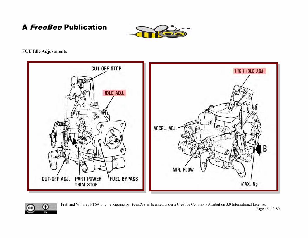
Idle Adjustments
Low Idle
Ensure there are no P3 or Py bleed leaks.
Once the engine has been started and dynamic rigging is being performed the first step is to verify the low idle setting.
The low idle setting is adjusted using the low idle setscrew located on the FCU.
It is important to verify that the setscrew is in fact adjusting the idle and a common method of doing that is to set the idle slightly below what is required and then bring the idle up to the required setting.
This low idle is the starting point for all of the rest of the rigging procedures and must be correct before proceeding with the following steps.
Engine speed is increased when turning the idle setscrew in – clockwise. It is very sensitive so is most often adjusted in ¼ of a flat.
1/16th turn = 1% change.
DO NOT CONFUSE THE LOW IDLE ADJUSTMENT WITH THE MINIMUM FLOW ADJUSTMENT!!
High Idle
Rig the controls to give you the correct high idle of the gas generator by adjusting the high idle stop on the FCU or the telescoping rod on the start control valve.(HI IDLE Adjustment Screw)
Pratt and Whitney PT6A Engine Rigging by FreeBee is licensed under a Creative Commons Attribution 3.0 International License. Page 44 of 80
A FreeBee Publication
FCU Idle Adjustments
Pratt and Whitney PT6A Engine Rigging by FreeBee is licensed under a Creative Commons Attribution 3.0 International License. Page 45 of 80

A FreeBee Publication
DeadBand Adjustments
Deadband is initially set with a specific gap between the setscrew and the lever face.
It is advised to check the power lever position on the forward and reverse deadband contact point before running the engine. They should be the same on both sides.
Dynamic Adjustments
Adjusting the deadband is a critical operation for the rest of the power lever rigging.
Forward Pickup Point
After starting the engine the power lever is moved forward until the gas generator speed just starts to increase. This lever position will be the forward Pickup Point. The pickup point is a combination of both deadband adjustment and FCU pickup point adjustment. Both power levers should have the same power lever position for forward pickup.
Check the additional (if any) amount of forward travel required to actually get gas generator increase speed point. If you have a significant difference between the deadband pickup point and the actual observed pickup point then the FCU pickup point is not
correct. A little bit of difference – if the same on both sides will not effect the system very much.
Reverse Pickup Point
After starting the engine the power lever is moved aft through the zero thrust point and a check made of actual gas generator speed increase is made. This is the reverse pickup point and like the forward one should be very close to or right on the deadband power lever position pickup point.
Again both sides need to be the same.
Setting The Pickup Points
First eliminate the difference in deadband and actual pickup points if present.
With the pickup points actually at the deadband points check to see that the forward and reverse points are at the correct power lever positions.
If the pickup points are too wide or too narrow adjust the deadband gap to correct.
If the pickup points are shifted – forward or aft – check the cambox rigging – input lever and track position.
Pratt and Whitney PT6A Engine Rigging by FreeBee is licensed under a Creative Commons Attribution 3.0 International License. Page 46 of 80

A FreeBee Publication
DeadBand Adjustment
Turning setscrew in – clockwise will reduce the gap and narrow the deadband range.
Pratt and Whitney PT6A Engine Rigging by FreeBee is licensed under a Creative Commons Attribution 3.0 International License. Page 47 of 80

A FreeBee Publication
Primary Blade Angle Check
After idle and deadband rigging has been completed the next check is for our primary blade angle.
As mentioned earlier the primary blade angle check is performed at the upper end of the forward beta range and indexes:
Fuel SchedulePower Lever PositionPropeller Blade Angle
Target Torque Graph
Using the correct chart for your propeller/engine application and using field elevation and outside air temperature determine the target torque for the existing day conditions.
Checking The Actual Torque
Start the engine and ensure propeller system is operating correctly.
Advance the power lever to obtain the correct propeller speed for you application.
Record the actual torque produced.
Adjustments For Torque Differences
On some installations the correct method of adjustment is by changing the forward teleflex cable clevis end.Others will only allow an adjustment of the adjustable flight idle stop assembly.A further method on some engines is to adjust the beta nuts on the propeller.
Follow the instructions for your installation taking into account that the propeller installed on the engine may be different from the factory installation.
When adjusting Beta Nuts it is imperative that they be adjust the exact same amount for each blade. Failure to maintain this symmetry may cause the beta ring system to jam or operate in an erratic manner.
Tolerances Allowed
Ensure + and – tolerances are within the limits specified.Tolerance allowed on each engine.Tolerance between two engines.
Once PBA within limits – Mark Position of Power Lever for further reference.
Pratt and Whitney PT6A Engine Rigging by FreeBee is licensed under a Creative Commons Attribution 3.0 International License. Page 48 of 80

A FreeBee Publication
Target Torque Graph – Typical Target Torque Tolerance = ± 40 Lbs' – 3 bladed propellers
= ± 20 Lbs' – 4 bladed propellersDifferences between engine - ± 20 Lbs' – 3 bladed propellers
± 10 Lbs' – 4 bladed propellers
Adjusting Beta Nuts
Moving beta nuts in will decrease blade angle and reduce torque.
Moving beta nuts out will increase blade angle and increase torque.
Amount / flat varies with propeller model.
1 flat = 30 Lbs - 3 bladed propellers1 flat = 35 Lbs – 4 bladed propellers
Pratt and Whitney PT6A Engine Rigging by FreeBee is licensed under a Creative Commons Attribution 3.0 International License. Page 49 of 80

A FreeBee Publication
Low Pitch Adjustable Stop
Pratt and Whitney PT6A Engine Rigging by FreeBee is licensed under a Creative Commons Attribution 3.0 International License. Page 50 of 80

A FreeBee Publication
Beta Backup – Secondary Low Pitch Stop
Pratt and Whitney PT6A Engine Rigging by FreeBee is licensed under a Creative Commons Attribution 3.0 International License. Page 51 of 80

A FreeBee Publication
Performance Run Check
The performance run process is undertaken at this time.
Maximum Propeller Speed Adjustment
The engine is run towards maximum power and the propeller maximum speed is checked. Do not overspeed the propeller during this check.
Ensure the propeller governor maximum speed setscrew is making contact with the stop and adjust as is required to maintain the correct speed as listed in the manual.
Once we know that the propeller is governing at the correct maximum speed we can proceed with a performance run.
Hydraulic Overspeed Governor Test
Complete the overspeed governor test to ensure the hydraulic overspeed governor is working correctly. The overspeed test will reset the speeder spring pressure and allow the overspeed governor to operate at a lower speed thus allowing the flight crew to check the operation.
Once test is completed ensure the overspeed solenoid has returned to closed position by running propeller speed above the reset speed.
TakeOff – Maximum Power Check
Advance the power lever to the maximum torque allowed – ensuring the ITT limits are not exceeded.
Mark the position of the power lever for reference. Reverse – Maximum Power Check
Reverse the power levers carefully to full reverse position and note:
Propeller SpeedGas Generator Speed
Propeller levers in full fine position.Do not exceed ITT limits when completing this test.
Be cautious when performing the test for the first time and do not allow the propeller speed to rise above 95%.
Fuel Topping Governor Adjustment – Np – Propeller Speed
Ensure propeller speed is governed by the fuel topping governor – if not correct – adjust the fuel topping governor reverse setscrew to give correct speed.
Re-rig linkage to compensate for changes made.
Pratt and Whitney PT6A Engine Rigging by FreeBee is licensed under a Creative Commons Attribution 3.0 International License. Page 52 of 80

A FreeBee Publication
Power Chart Propeller Governor Adjustments
Pratt and Whitney PT6A Engine Rigging by FreeBee is licensed under a Creative Commons Attribution 3.0 International License. Page 53 of 80

A FreeBee Publication
Propeller Feathering Checks
On some installations propeller feathering time must be adjusted to specifications in the manual. This is accomplished by adjusting the feathering time setscrew located on the propeller governor.
Turning the setscrew clockwise will cause the feathering time to increase.
In Flight Feathering Check
An in flight feathering check is required on some installations to ensure the propeller doesn't windmill.
Adjust the propeller feathering stop on those propellers that require this check.
Auto-Feather Checks
Perform the auto-feather checks as per the applicable flight manual and ensure the correct operation of the system.
Auto-Relight Checks
Perform the auto-relight check as per the applicable flight manual and ensure correct operation of the system.
Propeller Synchronization
Check operation of type 1 system in flight.
Type 2 systems can be checked – limited functions - on the ground but is best to be checked in flight.
Pratt and Whitney PT6A Engine Rigging by FreeBee is licensed under a Creative Commons Attribution 3.0 International License. Page 54 of 80

A FreeBee Publication
Propeller Synchronization
Pratt and Whitney PT6A Engine Rigging by FreeBee is licensed under a Creative Commons Attribution 3.0 International License. Page 55 of 80

A FreeBee Publication
Engine Acceleration Adjustments
Engine acceleration is controlled by changing the nominal spring pressure on the FCU bypass valve.
This is accomplished by rotation of the Chrome Dome on the fuel control unit.
Rotating in a clockwise direction will cause the engine to accelerate quicker. This will also cause higher ITT transient results.
Engines in multi-engine applications must have acceleration rates that are the same.
The allowable limit for adjustment is 3 clicks in either direction from the central position.
Adjustment of the acceleration control should be recorded in the logbook.
NoteAcceleration adjustment is not used to compensate for
power lever stagger conditions other than transient operation.
Slam Acceleration Check
Set Gas generator speed to 70% - rapidly move power lever to full forward stop – ensure torque and ITT limits not exceeded – pull power lever back to flight idle when gas generator speed reaches 93.5%. Record time from 70% to 93.5%.
Pratt and Whitney PT6A Engine Rigging by FreeBee is licensed under a Creative Commons Attribution 3.0 International License. Page 56 of 80

A FreeBee Publication
Acceleration Chart Acceleration Adjustment
Pratt and Whitney PT6A Engine Rigging by FreeBee is licensed under a Creative Commons Attribution 3.0 International License. Page 57 of 80

A FreeBee Publication
Power Lever Stagger Conditions
Careful rigging should result in a matched set of power levers throughout the operating range.
Due to differences in cambox wear and individual fuel control unit characteristics it is possible to have power lever stagger
Stagger Limits
While no official power lever stagger limits are published for most aircraft – the industry standard seems to be a maximum of ½ knob width is standard for most companies.
By analysis of the results of the dynamic rigging process you will be able to determine if the stagger is constant or progressive.
Progressive Stagger
Fix progressive stagger issues first.
Move the FCU arm to compensate for progressive stagger.
Move the arm towards the cambox to retard the leading lever and move the arm away from the cambox to advance the lagging lever. Split the difference when possible.
Constant Stagger
The fix for this is to adjust the length of the FCU interconnect rod.
Shorten the rod to retard the leading lever and lengthen the rod for the lagging lever. Split the difference when possible.
Stagger Not Possible To Remove
With a very worn system it is often impossible to remove all of the stagger.
Any forward stagger will be amplified in reverse.
In some cases the internal configurations of the individual fuel control units are different to the degree that a match is not possible.
In this condition the only fix is a FCU change.
Pratt and Whitney PT6A Engine Rigging by FreeBee is licensed under a Creative Commons Attribution 3.0 International License. Page 58 of 80

A FreeBee Publication
Constant Stagger Condition Progressive Stagger Condition
Pratt and Whitney PT6A Engine Rigging by FreeBee is licensed under a Creative Commons Attribution 3.0 International License. Page 59 of 80

A FreeBee Publication
Pratt and Whitney PT6A Engine Rigging by FreeBee is licensed under a Creative Commons Attribution 3.0 International License. Page 60 of 80

A FreeBee Publication
Condition Rectifications
Condition 1
Ideal – no adjustments needed.
Condition 2
Forward Pickup Points are not Correct – Adjust as required.Idle Dwell RE is greater than LE.
Condition 3Progressive Stagger Condition.Move the FCU arm to compensate for progressive stagger.
Move the arm towards the cambox to retard the leading lever and move the arm away from the cambox to advance the lagging lever. Split the difference when possible.
Condition 4
Forward Pickup Points are not Correct – Adjust as Required.Idle Dwell RE is greater than LE.Run engines and check for progressive stagger. Correct as above.
Condition 5
Reverse Pickup Points are not Correct – Idle Dwell RE is greater than LE. Adjust Idle Dwell and Track Points as required
Run engines and check for Progressive Reverse Stagger.
Condition 6
Forward and Reverse Pickup Points are not Correct – Adjust as Required. Idle Dwell RE is greater than LE or FCU Pickup Point is late.
Run Engine and check for Stagger.
Condition 7
Forward “Late” pickup point producing Fwd Constant StaggerReverse “Early pickup point producing Rev Constant StaggerPickup Points are shifted – Check Track Position and position of input arm.
Run engines and check for Stagger.
Pratt and Whitney PT6A Engine Rigging by FreeBee is licensed under a Creative Commons Attribution 3.0 International License. Page 61 of 80

A FreeBee Publication
Fuel Topping Governor – Reset Speed Check
The fuel topping governor is reset to 5% less than what the propeller governor is set when the power lever is moved to the full reverse position.
This speed can be checked without having to go all the way into reverse power – on some days you may ITT limit before getting to the max reverse limit.
By removing the interconnecting link and securing the lever in the full reverse position you are able to run the engine in the forward range and check the propeller limiting speed as the fuel topping governor should limit the propeller speed to 95%.Adjust as required.
Fuel Topping Governor Py Bleed Check
A speed limited propeller may be the result of a leaking fuel topping governor. If the adjustment of the CSU maximum speed setscrew doesn't change the speed it is possible that you have a bad CSU or that the fuel topping governor is leaking and bleeding Py pressure.
If you suspect or want to verify that there is no Py bleed leak inside the governor – remove the Py line at the governor and install a metal plug.
If the fuel topping governor air bleed valve was leaking you should now be able to see an increase in propeller speed as the fuel topping governor is no longer bleeding air and limiting the propeller speed prematurely.
Fuel Topping Governor Max Speed
The maximum speed setscrew adjustment is set on the propeller test stand and is not adjustable in the field.
Pratt and Whitney PT6A Engine Rigging by FreeBee is licensed under a Creative Commons Attribution 3.0 International License. Page 62 of 80

A FreeBee Publication
Fuel Topping Governor Linkage
Pratt and Whitney PT6A Engine Rigging by FreeBee is licensed under a Creative Commons Attribution 3.0 International License. Page 63 of 80

A FreeBee Publication
Gas Generator Maximum Speed
The FCU governor is set to deliver the maximum speed for the gas generator.
Under normal conditions we cannot push the power lever all the way to the maximum speed stop as the engine will reach maximum torque allowed or the maximum ITT allowed.
A flight test will require an aircraft altitude of almost 19,000 feet to accomplish the check.
Part Power Trim Check
In order to ensure the gas generator speed is set to the maximum allowed we use the part power trim block to lower the speed by a calibrated amount.
The trim stop is stowed in the operational position and we can move it so that it now rests against the maximum speed stop of the FCU and lock it in place.
The trim stop is a calibrated thickness and when we run the engine with the stop installed the power lever will not go all the way forward due to the new stop face presented.
The gas generator speed is checked at this time and compared to the value needed.
The maximum speed setscrew can be adjusted to give the correct reading if required.
Once the trim stop is stowed and locked out of the way – the further travel of the power lever to place the maximum speed setscrew on the stop will give the correct maximum speed of the gas generator.
Pratt and Whitney PT6A Engine Rigging by FreeBee is licensed under a Creative Commons Attribution 3.0 International License. Page 64 of 80

A FreeBee Publication
Gas Generator Maximum Speed and Part Power Trim Stop
Pratt and Whitney PT6A Engine Rigging by FreeBee is licensed under a Creative Commons Attribution 3.0 International License. Page 65 of 80
A FreeBee Publication
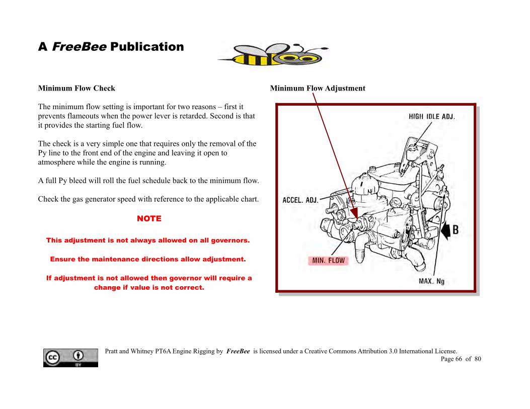
Minimum Flow Check
The minimum flow setting is important for two reasons – first it prevents flameouts when the power lever is retarded. Second is that it provides the starting fuel flow.
The check is a very simple one that requires only the removal of the Py line to the front end of the engine and leaving it open to atmosphere while the engine is running.
A full Py bleed will roll the fuel schedule back to the minimum flow.
Check the gas generator speed with reference to the applicable chart.
NOTE
This adjustment is not always allowed on all governors.
Ensure the maintenance directions allow adjustment.
If adjustment is not allowed then governor will require a change if value is not correct.
Minimum Flow Adjustment
Pratt and Whitney PT6A Engine Rigging by FreeBee is licensed under a Creative Commons Attribution 3.0 International License. Page 66 of 80

A FreeBee Publication
Minimum Flow Ng Speed Chart
Pratt and Whitney PT6A Engine Rigging by FreeBee is licensed under a Creative Commons Attribution 3.0 International License. Page 67 of 80

A FreeBee Publication
Rigging Summary1. Rig in accordance with the manufactures
instructions.
2. Record all of your adjustments.
3. Attention to detail in static rigging resultsin fewer engine runs and less work.
4. Calibrate any instruments thought to be inaccurate.
5. Think the problem through before making adjustments.
Rigging Aids1. Take Digital Photos of everything.2. Create checksheets and process documents.3. Use templates and rigging pins wherever
possible.4. Review logbooks and listen to flight crew
issues.
Pratt and Whitney PT6A Engine Rigging by FreeBee is licensed under a Creative Commons Attribution 3.0 International License. Page 68 of 80

A FreeBee Publication
For Training Only
Small Engine Series Guidelines
Use POH or Flight Manual forActual Aircraft Running
Pratt and Whitney PT6A Engine Rigging by FreeBee is licensed under a Creative Commons Attribution 3.0 International License. Page 69 of 80

A FreeBee Publication
Pratt and Whitney PT6A Engine Rigging by FreeBee is licensed under a Creative Commons Attribution 3.0 International License. Page 70 of 80
A FreeBee Publication
Pratt and Whitney PT6A Engine Rigging by FreeBee is licensed under a Creative Commons Attribution 3.0 International License. Page 71 of 80

A FreeBee Publication
Typical Engine Instruments
Pratt and Whitney PT6A Engine Rigging by FreeBee is licensed under a Creative Commons Attribution 3.0 International License. Page 72 of 80

A FreeBee Publication
Typical Engine Instrument Panel
Pratt and Whitney PT6A Engine Rigging by FreeBee is licensed under a Creative Commons Attribution 3.0 International License. Page 73 of 80

A FreeBee Publication
Digital Engine Gauges
Pratt and Whitney PT6A Engine Rigging by FreeBee is licensed under a Creative Commons Attribution 3.0 International License. Page 74 of 80

A FreeBee Publication
Starting Sequence
Pratt and Whitney PT6A Engine Rigging by FreeBee is licensed under a Creative Commons Attribution 3.0 International License. Page 75 of 80
A FreeBee Publication
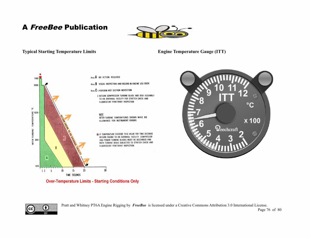
Typical Starting Temperature Limits Engine Temperature Gauge (ITT)
Pratt and Whitney PT6A Engine Rigging by FreeBee is licensed under a Creative Commons Attribution 3.0 International License. Page 76 of 80

A FreeBee Publication
Typical Engine Running Limits
Pratt and Whitney PT6A Engine Rigging by FreeBee is licensed under a Creative Commons Attribution 3.0 International License. Page 77 of 80

A FreeBee Publication
Typical Check List
Pratt and Whitney PT6A Engine Rigging by FreeBee is licensed under a Creative Commons Attribution 3.0 International License. Page 78 of 80

A FreeBee Publication
Notes
Pratt and Whitney PT6A Engine Rigging by FreeBee is licensed under a Creative Commons Attribution 3.0 International License. Page 79 of 80

A FreeBee Publication
References
P&W PT6A – Maintenance Manuals / Training ManualsBeech Aircraft – Maintenance Manuals / Training ManualsDHC Aircraft – Maintenance Manuals / Training Manuals
Hawker / Beech / Raytheon Publications and Photos.
A special thanks to all the illustrators for the above publications. Without your drawings and diagrams, this guide would not have much impact. Wherever possible I have left the accreditation on the drawings.
The truth is that the “Company Illustrator” is usually the last to gain any recognition for their work. - Thanks.
Pratt and Whitney PT6A Engine Rigging by FreeBee is licensed under a Creative Commons Attribution 3.0 International License. Page 80 of 80