smart building · pdf file · 2018-03-05related to the coil geometry within the...
TRANSCRIPT

1 © 2016 ANSYS, Inc. February 27, 2018 ANSYS Confidential
SMART BUILDING SIMULATION

2 © 2016 ANSYS, Inc. February 27, 2018 ANSYS Confidential
Agenda
• Overview
• Smart Home
• WPT
• Beam forming
• Smart Home Example
• Extension using System

3 © 2016 ANSYS, Inc. February 27, 2018 ANSYS Confidential
Overview

4 © 2016 ANSYS, Inc. February 27, 2018 ANSYS Confidential
Agenda• Many different aspects to consider
Source internet

5 © 2016 ANSYS, Inc. February 27, 2018 ANSYS Confidential
Let’s start with a smart home
Source internet

6 © 2016 ANSYS, Inc. February 27, 2018 ANSYS Confidential
ANSYS Solutions for Wireless Power Transfer
7 © 2016 ANSYS, Inc. February 27, 2018 ANSYS Confidential
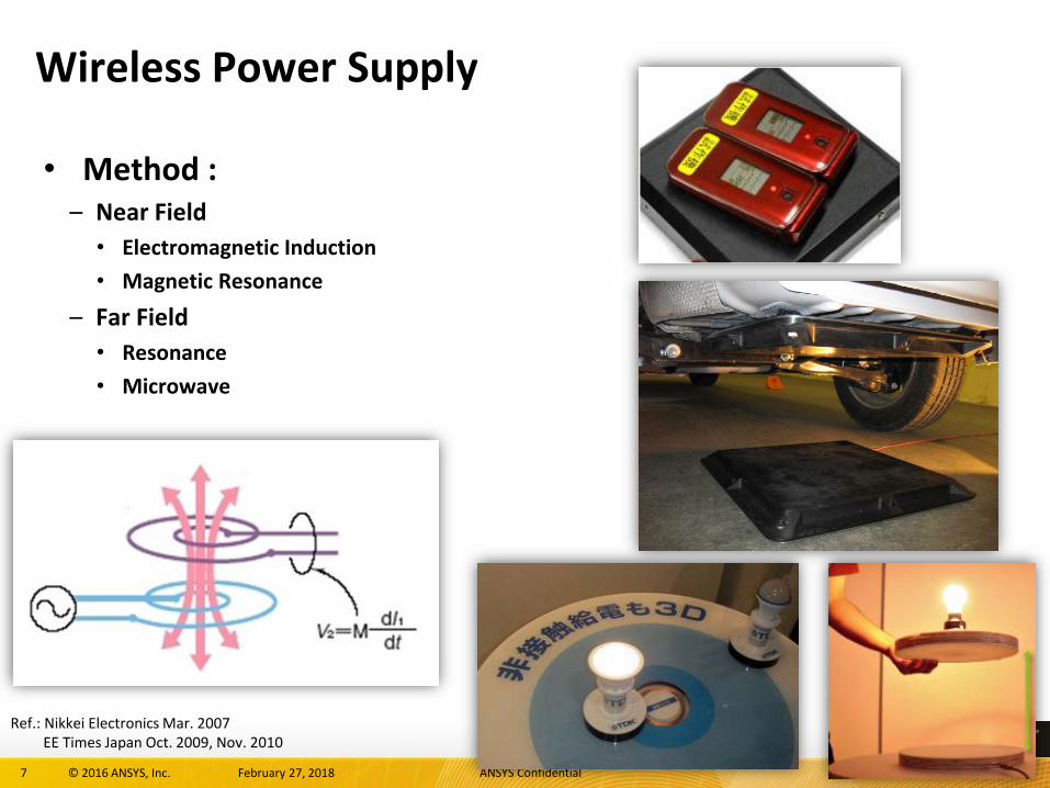
Wireless Power Supply
• Method :– Near Field
• Electromagnetic Induction
• Magnetic Resonance
– Far Field
• Resonance
• Microwave
Ref.: Nikkei Electronics Mar. 2007EE Times Japan Oct. 2009, Nov. 2010

8 © 2016 ANSYS, Inc. February 27, 2018 ANSYS Confidential
Method Map
Ref: EE Times Japan 2009.10
1mm 1cm 10cm 1m 10m 100m
100%
50%
0%
Transfer Distance
Effi
cien
cy Resonance type
Induction type(~15W) Induction type(~50kW)
Microwave type
Near Field
Far Field
HFSSDesigner
MaxwellSimplorer
10 © 2016 ANSYS, Inc. February 27, 2018 ANSYS Confidential
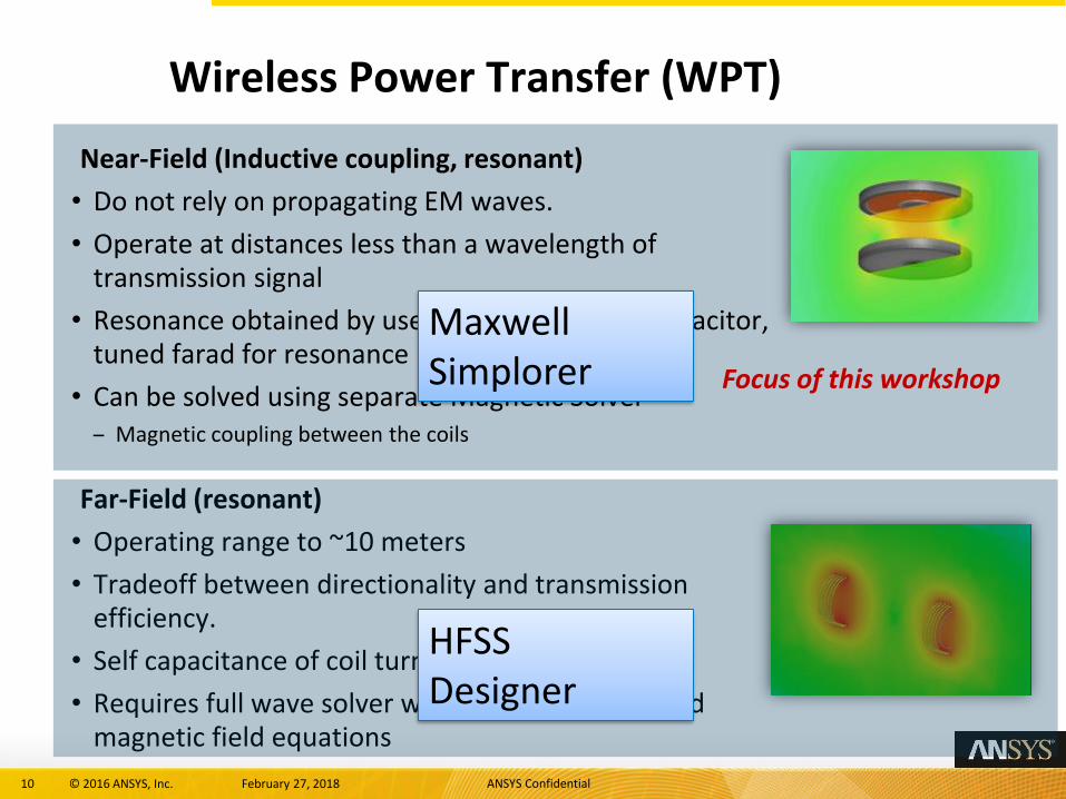
Near-Field (Inductive coupling, resonant)
• Do not rely on propagating EM waves.
• Operate at distances less than a wavelength of transmission signal
• Resonance obtained by use of external circuit capacitor, tuned farad for resonance
• Can be solved using separate Magnetic Solver– Magnetic coupling between the coils
Far-Field (resonant)
• Operating range to ~10 meters
• Tradeoff between directionality and transmission efficiency.
• Self capacitance of coil turns are of importance
• Requires full wave solver with coupled electric and magnetic field equations
Wireless Power Transfer (WPT)
Focus of this workshop
MaxwellSimplorer
HFSSDesigner

11 © 2016 ANSYS, Inc. February 27, 2018 ANSYS Confidential
Let’s see the parking lot
Application Example
Objective: Wireless Power Transfer
To design electromagnetic power transfer from a coil to another coil based on inductive coupling and/or resonant (wireless) coupling
ANSYS Solution
• Using ANSYS Maxwell to calculate the inductive coupling to design the coil topologies
• Extract the frequency dependent model from eddy solver based on SSM (state-space-model)
• Using ANSYS Simplorer to import the SSM and build the entire electric drive system.
Design Impact
• Designing entire system analyzing the nonlinear interactions among various drive components
• Reduce the design cycle accounting for parametric variations related to the coil geometry within the same drive system configuration

12 © 2016 ANSYS, Inc. February 27, 2018 ANSYS Confidential
Applications of Maxwell

13 © 2016 ANSYS, Inc. February 27, 2018 ANSYS Confidential
Geometry
14 © 2016 ANSYS, Inc. February 27, 2018 ANSYS Confidential
0.00 100.00 200.00 300.00 400.00H (A_per_meter)
0.00
0.10
0.20
0.30
0.40
0.50
0.60
B (
tesla
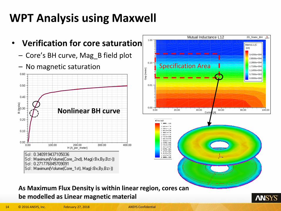
)WPT Analysis using Maxwell
• Verification for core saturation– Core’s BH curve, Mag_B field plot
– No magnetic saturation
Nonlinear BH curve 0.00 20.00 40.00 60.00 80.00 100.00Current [A]
0.00
0.01
0.10
1.00
Ga
p [m
ete
r]
2D_Static_BHMutual Inductance L12 ANSOFT
Matrix1.L(C
[nH]
0.0000e+000
5.7000e+003
1.1400e+004
1.7100e+004
2.2800e+004
2.8500e+004
3.4200e+004
Specification Area
As Maximum Flux Density is within linear region, cores can be modelled as Linear magnetic material

15 © 2016 ANSYS, Inc. February 27, 2018 ANSYS Confidential
Parametric Analysis using Maxwell (Gap, Sliding)
Mutual Inductance Vs Gap Vs Slide
Coupling Coefficient Vs Gap Vs Slide

16 © 2016 ANSYS, Inc. February 27, 2018 ANSYS Confidential
Loss Calculation
• In Addition to Ohmic losses in windings, the system is subjected to other losses
– Hysteresis Losses in Magnetic Core Plates
∝ (Frequency)
– Eddy Current Losses in the Conducting shield plates
∝ (Frequency)2
• Total Power losses are function of Frequency
• A Frequency domain analysis can be used to predict the losses in the system

17 © 2016 ANSYS, Inc. February 27, 2018 ANSYS Confidential
Loss Calculation: Frequency Sweep
Core Loss Vs Frequency
Core Losses in the Core Plates at 100 kHz
18 © 2016 ANSYS, Inc. February 27, 2018 ANSYS Confidential
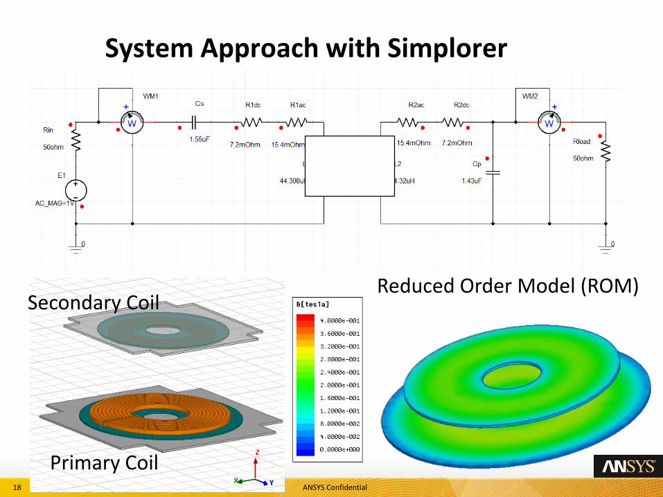
System Approach with Simplorer
Secondary Coil
Primary Coil
Reduced Order Model (ROM)
19 © 2016 ANSYS, Inc. February 27, 2018 ANSYS Confidential
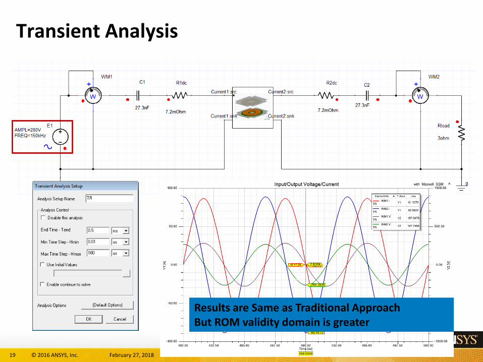
Transient Analysis
Results are Same as Traditional ApproachBut ROM validity domain is greater

20 © 2016 ANSYS, Inc. February 27, 2018 ANSYS Confidential
Efficiency Map
• Output/Input Power
• Tuned capacitance for each conditions
90%
50%
20%
[%]100
cos
in
out
P
P
VIP
Effi
cien
cy[%
]
Sliding [mm]Gap [mm]
Max.96%

21 © 2016 ANSYS, Inc. February 27, 2018 ANSYS Confidential
System Simulation – WPT
0
0
0
R1
(1/87-0.004) ohm
R2
(1/348-0.001) ohm
Cs
1.93uF
Cp
5.24uF
Rload
10ohm
W
+
WM1
W
+
WM2
D4
D3
D2
D1
IGBT4
IGBT3
IGBT2
IGBT1
C1
1000uF
TRANS4
DT4
TRANS3
SINE1.VAL > TRIANG1.VAL
TRANS2
DT1
TRANS1
SINE1.VAL < TRIANG1.VAL
STATE_11_4
SET: TSV4:=0SET: TSV3:=0SET: TSV2:=0
SET: TSV1:=0DEL: DT4##Dead_Time
STATE_11_3
SET: TSV4:=0SET: TSV3:=1SET: TSV2:=1
SET: TSV1:=0
STATE_11_2
SET: TSV4:=0
SET: TSV3:=0SET: TSV2:=0
SET: TSV1:=0DEL: DT1##Dead_Time
STATE_11_1
SET: TSV4:=1
SET: TSV3:=0SET: TSV2:=0
SET: TSV1:=1
TRIANG1
AMPL=1FREQ=Carrier_Freq
SINE1
AMPL=Modulation_IndexFREQ=Frequency
ICA:FML_INIT1
Modulation_Index:=0
Carrier_Freq:=10kFrequency:=10k
DC_Source:=200Dead_Time:=2u
~
3PHAS
~
~
A * sin (2 * pi * f * t + PHI + phi_u)
PHI = 0°
PHI = -120°
PHI = -240°
THREE_PHASE1
D5
D6
D7
D8
D9
D10 Battery
- +
LBATT_A1
D11
D12
D13
D14
C2
1e-006farad
0.00 0.25 0.50 0.75 1.00 1.25 1.50 1.75 2.00Time [ms]
-40.00
-20.00
0.00
20.00
40.00
Y1 [A
]
Curve Info rms
WM1.ITR 9.4139
WM2.ITR 10.5939
0.00 0.25 0.50 0.75 1.00 1.25 1.50 1.75 2.00Time [ms]
-300.00
-100.00
100.00
300.00Y
1 [V
]Curve Info rms
WM1.VTR 154.9045
WM2.VTR 120.2425
1.90 1.92 1.94 1.96 1.98 2.00Time [ms]
-40.00
-20.00
0.00
20.00
40.00
Y1 [A
]
-200.00
-100.00
0.00
100.00
200.00
Y2 [V
]
MX1: 1.9753MX2: 1.9783
-6.0797
-1.2036-0.0090
131.1979
-0.51411.340627.9814
156.0455
0.0030
Curve Info Y Axis rms
WM1.ITR Y1 9.3501
WM2.ITR Y1 10.5176
WM1.VTR Y2 153.6594
WM2.VTR Y2 119.4615
Current_1st_1:src
Current_1st_2:src
Current_2nd_1:src
Current_2nd_2:src
Current_1st_1:snk
Current_1st_2:snk
Current_2nd_1:snk
Current_2nd_2:snk
0
0
0
R1
(1/87-0.004) ohm
R2
(1/348-0.001) ohm
Cs
1.93uF
Cp
5.24uF
Rload
10ohm
W
+
WM1
W
+
WM2
D4
D3
D2
D1
IGBT4
IGBT3
IGBT2
IGBT1
C1
1000uF
TRANS4
DT4
TRANS3
SINE1.VAL > TRIANG1.VAL
TRANS2
DT1
TRANS1
SINE1.VAL < TRIANG1.VAL
STATE_11_4
SET: TSV4:=0SET: TSV3:=0SET: TSV2:=0
SET: TSV1:=0DEL: DT4##Dead_Time
STATE_11_3
SET: TSV4:=0SET: TSV3:=1SET: TSV2:=1
SET: TSV1:=0
STATE_11_2
SET: TSV4:=0
SET: TSV3:=0SET: TSV2:=0
SET: TSV1:=0DEL: DT1##Dead_Time
STATE_11_1
SET: TSV4:=1
SET: TSV3:=0SET: TSV2:=0
SET: TSV1:=1
TRIANG1
AMPL=1FREQ=Carrier_Freq
SINE1
AMPL=Modulation_IndexFREQ=Frequency
ICA:FML_INIT1
Modulation_Index:=0
Carrier_Freq:=10kFrequency:=10k
DC_Source:=200Dead_Time:=2u
~
3PHAS
~
~
A * sin (2 * pi * f * t + PHI + phi_u)
PHI = 0°
PHI = -120°
PHI = -240°
THREE_PHASE1
D5
D6
D7
D8
D9
D10 Battery
- +
LBATT_A1
D11
D12
D13
D14
C2
1e-006farad
0.00 0.25 0.50 0.75 1.00 1.25 1.50 1.75 2.00Time [ms]
-40.00
-20.00
0.00
20.00
40.00
Y1 [A
]
Curve Info rms
WM1.ITR 9.4139
WM2.ITR 10.5939
0.00 0.25 0.50 0.75 1.00 1.25 1.50 1.75 2.00Time [ms]
-300.00
-100.00
100.00
300.00
Y1 [V
]
Curve Info rms
WM1.VTR 154.9045
WM2.VTR 120.2425
1.90 1.92 1.94 1.96 1.98 2.00Time [ms]
-40.00
-20.00
0.00
20.00
40.00
Y1 [A
]
-200.00
-100.00
0.00
100.00
200.00
Y2 [V
]
MX1: 1.9753MX2: 1.9783
-6.0797
-1.2036-0.0090
131.1979
-0.51411.340627.9814
156.0455
0.0030
Curve Info Y Axis rms
WM1.ITR Y1 9.3501
WM2.ITR Y1 10.5176
WM1.VTR Y2 153.6594
WM2.VTR Y2 119.4615
Current_1st_1:src
Current_1st_2:src
Current_2nd_1:src
Current_2nd_2:src
Current_1st_1:snk
Current_1st_2:snk
Current_2nd_1:snk
Current_2nd_2:snk
AC200V Rectify Inverter
Wireless Power Transformer Battery
Controller

22 © 2016 ANSYS, Inc. February 27, 2018 ANSYS Confidential
Wireless Charging

23 © 2016 ANSYS, Inc. February 27, 2018 ANSYS Confidential
At home: Wireless charger > Transformer Design
Optimize the performance of Wireless Power Transformer

24 © 2016 ANSYS, Inc. February 27, 2018 ANSYS Confidential
Optimized Transformer in Maxwell
Coupling Coefficient Vs Gap Vs Slide
Wireless charger in operation
ChargerSliding
Charger Gap
25 © 2016 ANSYS, Inc. February 27, 2018 ANSYS Confidential
Generic Adaptive Beamforming using HFSS & SBR+

26 © 2016 ANSYS, Inc. February 27, 2018 ANSYS Confidential
Simple Beamforming with Pilot Signal Example
Device (Beacon Antenna)
Phased Array
• Device transmits pilot (beacon) signal• Phased array samples mag and phase of
known received signal• Capture channel state information
• Apply beamforming algorithm to drive phased array (including null steering if needed)
• Resulting pattern contains all information about channel (maybe not just a simple beam)

27 © 2016 ANSYS, Inc. February 27, 2018 ANSYS Confidential
faDDM Solution – 256 Element Array
*simulated in parallel on 32 cores
Considered Array Antenna
Detail of 1 unit array

28 © 2016 ANSYS, Inc. February 27, 2018 ANSYS Confidential
Test Cases
• Line of Sight Adaptive Beamforming– Beacon antenna and array have line of sight
– Array tracks device location in 3D space
• Beamforming with No line of sight– Adaptive beamforming while device transitions to a no line of sight
scenario
• Real World Indoor Environment– Adaptive beamforming in scenario with complex scattering
environment
– Multiple transmit devices

33 © 2016 ANSYS, Inc. February 27, 2018 ANSYS Confidential
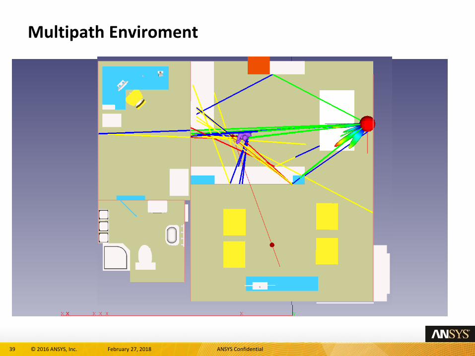
Real World Indoor Environment

34 © 2016 ANSYS, Inc. February 27, 2018 ANSYS Confidential
Real World Indoor Environment
• Complex Scattering Environment– Dielectric and Metal
• Conjugate Beamforming determines most effective weighting of phased array based on channel information captured by beacon
• Changes to environment are compensated for by array
Device/Beacon
Array

35 © 2016 ANSYS, Inc. February 27, 2018 ANSYS Confidential
Beamforming with Blockage
Scene 1 – No obstructions Scene 2 – Partial Obstruction
Device/Beacon
Obstruction

36 © 2016 ANSYS, Inc. February 27, 2018 ANSYS Confidential
Scene 2 – Partial Obstruction
Device/Beacon
Obstruction
Beam develops for alternate path due to obstruction

37 © 2016 ANSYS, Inc. February 27, 2018 ANSYS Confidential
Multiple Devices
Device 1
Device 2
Multiple Devices Operating in Same EnvironmentBeamforming used to serve both devices or steer null into direction of 1 device to limit interference

38 © 2016 ANSYS, Inc. February 27, 2018 ANSYS Confidential
Multiple Devices – 2 Scenarios
Scene 1 – No obstructions2 Beams formed, one in the
direction of each device
Scene 2 – Partial ObstructionAt least 3 beams formed to exploit the multi-
path environment to reduce impact of blockage
Obstruction
Device/Beacon
39 © 2016 ANSYS, Inc. February 27, 2018 ANSYS Confidential
Multipath Enviroment

40 © 2016 ANSYS, Inc. February 27, 2018 ANSYS Confidential
Summary
• A basic beamforming solution/validation approach is shown
• Simulation approach could be extended to shown more complex beamforming algorithms
• Applications could include– Communications, data transmission: 60GHz and other 5G technologies
– HF Wireless Power Transfer

41 © 2016 ANSYS, Inc. February 27, 2018 ANSYS Confidential
SMART HOME
Safa Salman
Charlotte Blair
Peter Krenz
Saeed Jahangirian
Mehdi Abarham
Laila Salman

42 © 2016 ANSYS, Inc. February 27, 2018 ANSYS Confidential
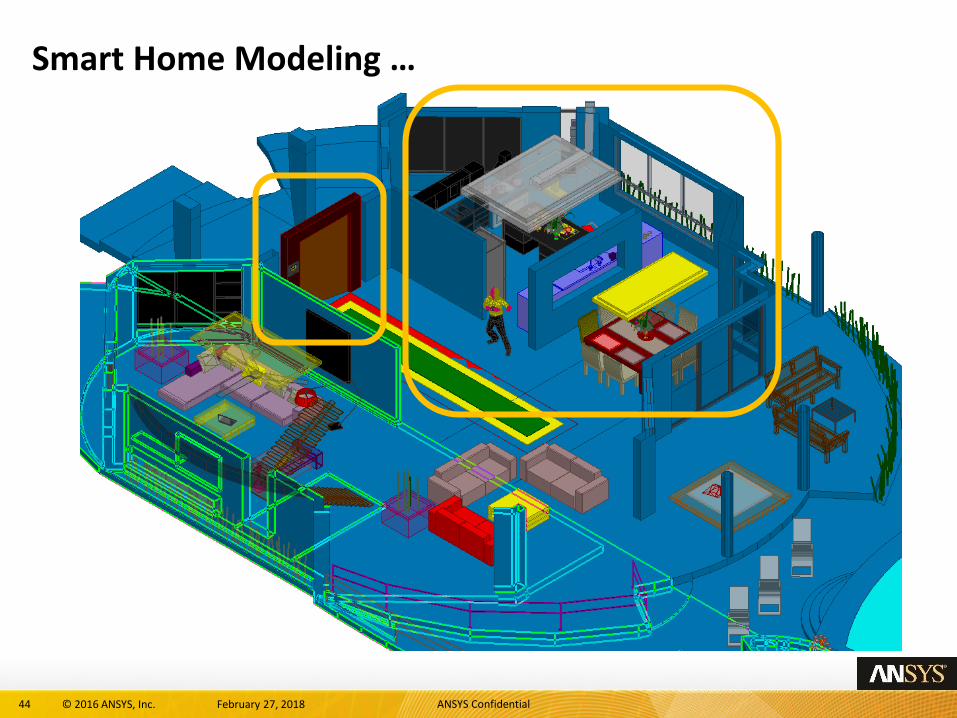
Engineering Challenges …
House CAD Model provided courtesy of Juliano Mologni, ESSS
44 © 2016 ANSYS, Inc. February 27, 2018 ANSYS Confidential
Smart Home Modeling …

46 © 2016 ANSYS, Inc. February 27, 2018 ANSYS Confidential
Smart Motion Detection & Surveillance Camera

47 © 2016 ANSYS, Inc. February 27, 2018 ANSYS Confidential
Energy Control Unit
Triple Band Antenna
@ 900 MHz
@ 2.45 GHz
@ 5.8 GHz

48 © 2016 ANSYS, Inc. February 27, 2018 ANSYS Confidential
Energy Control Unit + Light Bulb

49 © 2016 ANSYS, Inc. February 27, 2018 ANSYS Confidential
Thermal Analysis of LED Light Bulb
ANSYS DesignModeler ANSYS Icepak ANSYS MechanicalANSYS HFSS
ANSYS DesignXplorer
Temperature contour of the LED light bulb
(external parts)
Orthotropic thermal conductivity map (Kz) of the PCB
left: top layer; right: bottom layer
Temperature contour of the LED heatsink
and LED sources

50 © 2016 ANSYS, Inc. February 27, 2018 ANSYS Confidential
Thermal Stress Analysis of LED Light Bulb
Imported Temperature Map of LED light bulb
Calculated deformation based on temperature map

51 © 2016 ANSYS, Inc. February 27, 2018 ANSYS Confidential
Smart Home HVAC System with Sensing Actuator

52 © 2016 ANSYS, Inc. February 27, 2018 ANSYS Confidential
ANSYS CFD Simulations Enable Virtual Energy Efficient Homes
Time = 0 sec
Occupant enters
Time = 0 sec
Actuator opens the duct damper
Time = 0.5 sec
Damper fully open, maximum flow of cold air
Iso-surfaces of Temperature at 55 F

53 © 2016 ANSYS, Inc. February 27, 2018 ANSYS Confidential
Full Virtual Model of Zonal Cooling Controlled by IoT Devices

54 © 2016 ANSYS, Inc. February 27, 2018 ANSYS Confidential
CFD Provides Insight to System Operations
Air Velocity at 41 sec after Damper Opening

56 © 2016 ANSYS, Inc. February 27, 2018 ANSYS Confidential
SMART HOME EXTENDED

57 © 2016 ANSYS, Inc. February 27, 2018 ANSYS Confidential
It’s a system
Source internet

58 © 2016 ANSYS, Inc. February 27, 2018 ANSYS Confidential
Integrating Components and Subsystems into the SystemAnsys solution system: Simplorer
Reduced Order Model Creation
Functional Mockup Interface (FMI)
3rd Party System
Modeling tools
(AMESim, Simulink,
Dymola, GT Suite etc.)
Embedded Software Integration
ANSYS SCADE
C Code
Co-simulationwith 3D Physics
ANSYS 3D Physics
MechEM ThermalFluid
Multi-Domain Model Libraries
Language-Based Modeling
VHDL-AMS
C/C++
SPICE
SML
Modelica
Analog
Digital
Multi-Domain
App-Specific
Power Systems
Manufacturers

59 © 2016 ANSYS, Inc. February 27, 2018 ANSYS Confidential
Behavioral Models in Product Development In Many Forms…
Circuits
Block Diagrams
Co-simulation
Digital/Mixed-Signal
State Machines
Reduced-Order Models
Multi-Domain Assemblies
C Code, FMUs
Data-Driven / Look-up Tables

60 © 2016 ANSYS, Inc. February 27, 2018 ANSYS Confidential
Reduced Order Models (ROMs) for Multiple Physics, Multiple Problem Types
61 © 2016 ANSYS, Inc. February 27, 2018 ANSYS Confidential
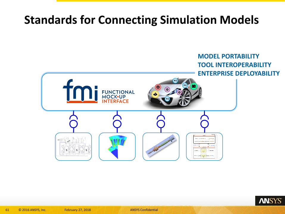
Standards for Connecting Simulation Models
MODEL PORTABILITYTOOL INTEROPERABILITYENTERPRISE DEPLOYABILITY

62 © 2016 ANSYS, Inc. February 27, 2018 ANSYS Confidential
0
00 0
PMSM_DQn1
n2
n3
m1
SIMPARAM1
L1
L2
L3
N1
N2
N3
I1 I3
I_Motor
-
~P
N
V
U
W
V1 V2 V3 V4 V5 V6
U1E1
EMF=1000V
A B C
N
U_UMR
PWM
Modulator
DC-Link
Voltage
Integrating
Current
Sampling
Mechanical
Angle Input
u1
u2
Udc
u3
V1
V2
V3
V4
V5
V6
I_1
I_3
I1f
I3f
phi_m
phi_el
w_el
FPGA
PWM_3PH1
+
V
VM1
+
FSM_ROTB1
A B C
N
U_MOT
L1
L2
L3
N1
N2
N3
S_Motor
CTRL=S1
OFF
SET: S1:=0
Time >= Tsw ON
SET: S1:=1
MASS_ROTB1
A
AM4
C1
C2
R1
R2
R3 L1
TF_ROTB1
w_ref
phi_el
i1f
i3f
w_el
u1
u2
u3
n_ref
TDELAY=5ms
AMPL=n_ref-n0
TRISE=300ms
OFF=n0
Load_Torque
TDELAY=t_load
AMPL=trq_load
TRISE=20ms
OFF=0
Power Source
Power Electronics:Inverter
Motor(PMSM)
MechanicalDynamics & Loads
Power Cables
Embedded Control
Behavioral Models in Product Development From Many Sources…
• HVAC• E-WINDOWS/STORES• ENERGY
MANAGEMENT• HEATING
MANAGEMENT• E-DEVICES• PRESENCE
DETECTION• …

63 © 2016 ANSYS, Inc. February 27, 2018 ANSYS Confidential
PERSPECTIVES

64 © 2016 ANSYS, Inc. February 27, 2018 ANSYS Confidential
Extension to building
Source internet

65 © 2016 ANSYS, Inc. February 27, 2018 ANSYS Confidential
… and SMART CITY (or PLANT)
Source internet
Connected to smart grid

66 © 2016 ANSYS, Inc. February 27, 2018 ANSYS Confidential
QUESTIONS/DISCUSSION