smart cutting tools and smart machining: development ...types of smart cutting tools, including a...
TRANSCRIPT
ORIGINAL ARTICLE
Smart Cutting Tools and Smart Machining: DevelopmentApproaches, and Their Implementation and ApplicationPerspectives
Kai Cheng1 • Zhi-Chao Niu1 • Robin C. Wang1 • Richard Rakowski1 •
Richard Bateman1
Received: 19 December 2016 / Revised: 8 May 2017 / Accepted: 24 July 2017
� The Author(s) 2017. This article is an open access publication
Abstract Smart machining has tremendous potential and
is becoming one of new generation high value precision
manufacturing technologies in line with the advance of
Industry 4.0 concepts. This paper presents some innovative
design concepts and, in particular, the development of four
types of smart cutting tools, including a force-based smart
cutting tool, a temperature-based internally-cooled cutting
tool, a fast tool servo (FTS) and smart collets for ultra-
precision and micro manufacturing purposes. Implemen-
tation and application perspectives of these smart cutting
tools are explored and discussed particularly for smart
machining against a number of industrial application
requirements. They are contamination-free machining,
machining of tool-wear-prone Si-based infra-red devices
and medical applications, high speed micro milling and
micro drilling, etc. Furthermore, implementation tech-
niques are presented focusing on: (a) plug-and-produce
design principle and the associated smart control algo-
rithms, (b) piezoelectric film and surface acoustic wave
transducers to measure cutting forces in process, (c) critical
cutting temperature control in real-time machining, (d) in-
process calibration through machining trials, (e) FE-based
design and analysis of smart cutting tools, and (f) applica-
tion exemplars on adaptive smart machining.
Keywords Smart cutting tool � Smart machining � Fast toolservo (FTS) � Precision machining � Micro manufacturing �Smart tooling
1 Introduction
Smart tooling and smart machining have tremendous
potential and are drawing attention as one of next gen-
eration precision machining technologies particularly in
the Industry 4.0 context [1–5]. In modern advanced
manufacturing, it is becoming an essential trend for
machining components with an ever increasing dimen-
sional/form accuracy and finer surface roughness, even
surface functionality requirement. In high precision
machining, however, to position the cutting tool with
such high accuracy and repeatability is the key and this
is normally undertaken in a ‘‘passive’’ manner, i.e., the
tool’s position relying on the slideways’ positioning
accuracy but without measuring the tool cutting beha-
viour and process conditions. Furthermore, for many
high value precision machining processes, it is important
to use smart cutting tools to carry out the processes in a
‘proactive’ manner, in order to cope with machining
dynamics, process variations and complexity. For
instance, ultra-precision and micro machining, with the
surface roughness normally at the nanometric scale and
features/patterns at the micrometer level, is increasingly
and continuously demanded particularly for high preci-
sion components and products with improved function-
ality and performance. The smart precision and micro
manufacturing in a ‘proactive’ manner will be the way
forward [6].
Aiming at high quality surfaces and dimensional/form
accuracy, some monitoring methods have been proposed to
Supported by the UK Technology Strategy Board (TSB) and Innovate
UK (SEEM Project, Contract No.: BD266E; KTP Project, Contract
No.: 9277).
& Kai Cheng
1 College of Engineering, Design and Physical Sciences,
Brunel University London, Uxbridge UB8 3PH, UK
123
Chin. J. Mech. Eng.
DOI 10.1007/s10033-017-0183-4
monitor cutting forces with high precision and the process
conditions. The variations of the cutting forces are most
likely related to the tool wear or other process conditions
and therefore will have direct influences on the machining
outcomes [7–9]. Tool wear or tool breakage can also
increase the cutting forces and vibrations in the machining
system, which will result in poor surface roughness, loss of
the form and dimensional accuracy, and even chatter marks
on machined surfaces [10]. In order to avoid such manu-
facturing defects or tool damages, some devices are
designed and developed to measure the cutting forces and
cutting dynamics. For instance, dynamometers are devel-
oped by researchers and industrial companies to measure
cutting forces and the process dynamics in high precision
and wide bandwidth. Currently, however, dynamometers
have some limitations in their industrial application, such
as their costs and reliability in stringent production envi-
ronment. Furthermore, dynamometers are not applicable
for layout-constrained machines and tooling setup, due to
their size and weight. The dynamometer could also inter-
fere with the cutting process and performance because of
the tooling stiffness reduction in the machining system
[11].
Some high value components require to be machined
in a contamination-free environment, which means
coolant cannot be applied during the machining. How-
ever, dry cutting condition would lead to tool wear and
high cutting temperature, and poor surface quality would
thus occur and tool life be shortened. Some materials,
such as aluminum and magnesium alloys, are not rec-
ommended for applying direct dry-cutting, since the
cutting tool is prone to suffering excessive built-up edge
(BUE). So for high precision and micro machining, there
is a need for new sensor technologies to be applied to
further exploit and understand the cutting mechanics and
machining process [6].
Based on the underlying principle and application
requirements above, four types of smart tools are
developed, including a cutting force based smart tool, a
cutting temperature sensing oriented internally cooled
cutting tool a fast tool servo (FTS), and smart collets
for ultraprecision and micro machining purposes. This
paper presents the design concept, development pro-
cesses, application principles for the above smart tools,
for high precision and micro machining in particular.
The paper also explores and discusses the implemen-
tation and application perspectives of those smart tools
against the smart machining requirements from a
number of industrial applications, such as microma-
chining maintained with constant cutting force, extra-
high speed micro drilling, and contamination-free
machining of medical device or explosive materials
[12, 13].
2 Smart Cutting Tools and Smart Machining
Smart cutting tools are built with autonomous sensing
and self-learning capabilities, and operate in-process
sensoring and actuation and will thus likely lead to
improved part quality and surface roughness, reduced
production costs and higher manufacturing productivity.
They are characterized with some distinguished features
such as plug-and-play, autonomous operation, self-con-
dition monitoring, self-positioning adjustment, self-
learning, compatible with highly automated CNC envi-
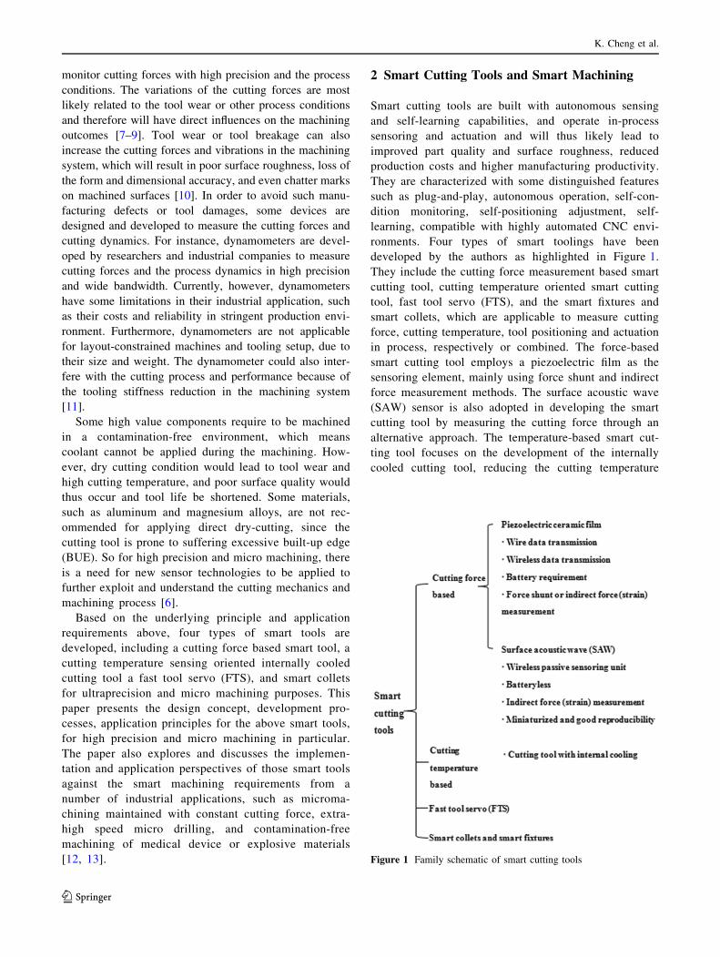
ronments. Four types of smart toolings have been
developed by the authors as highlighted in Figure 1.
They include the cutting force measurement based smart
cutting tool, cutting temperature oriented smart cutting
tool, fast tool servo (FTS), and the smart fixtures and
smart collets, which are applicable to measure cutting
force, cutting temperature, tool positioning and actuation
in process, respectively or combined. The force-based
smart cutting tool employs a piezoelectric film as the
sensoring element, mainly using force shunt and indirect
force measurement methods. The surface acoustic wave
(SAW) sensor is also adopted in developing the smart
cutting tool by measuring the cutting force through an
alternative approach. The temperature-based smart cut-
ting tool focuses on the development of the internally
cooled cutting tool, reducing the cutting temperature
Figure 1 Family schematic of smart cutting tools
K. Cheng et al.
123
around the cutting edge, in order to extend tool life and
produce a better surface finish at the workpiece. It can
also be extended for the use of measuring the cutting
temperature in a specific machining environment. A fast
tool servo is normally employed to position the cutting
tool operating in a dynamic cutting and actuation sce-
nario with a high precision accuracy and wide band-
width, for precision machining of complex geometrical
features in particular. Smart collets and smart fixtures
are essential as enabling machining system devices for
smart machining.
Smart machining has the unique manufacturing advan-
tages, which will likely result in:
(1) Minimizing the tool paths and machining time;
(2) Improving the component surface finish;
(3) Maximizing the cutting tool life and cutting
performance;
(4) Machining complex geometrized components with
improved precision and efficiency, such as thin-wall
structures, hollow cylinders or slender shafts;
(5) Process optimization in light of autonomous sensing;
(6) Self-learning and performance improvement in the
process;
(7) Sensing of the cutting process dynamically, covering
cutting forces, chip formation, and interactions at the
cutting zone.
3 Force-based Smart Cutting Tools
3.1 Smart Cutting Tool Using Piezoelectric Films
3.1.1 Design Configuration
Cutting force can be generally measured by three methods,
i.e., using force shunt, direct force measurement and indi-
rect force measurement. Regarding direct cutting force
measurement method, a sensoring unit is mounted directly
in the force path in order to measure the entire process
force. Conversely, the indirect force measurement method
measures the force through a strain proportional to the
process force [14]. For using the force shunt method, a
fraction of the cutting force passing through the sensoring
unit is measured. One smart cutting tool (namely, smart
tool 1) as shown in Figure 2 uses the force shunt and the
indirect force measurement to detect the cutting force
respectively.
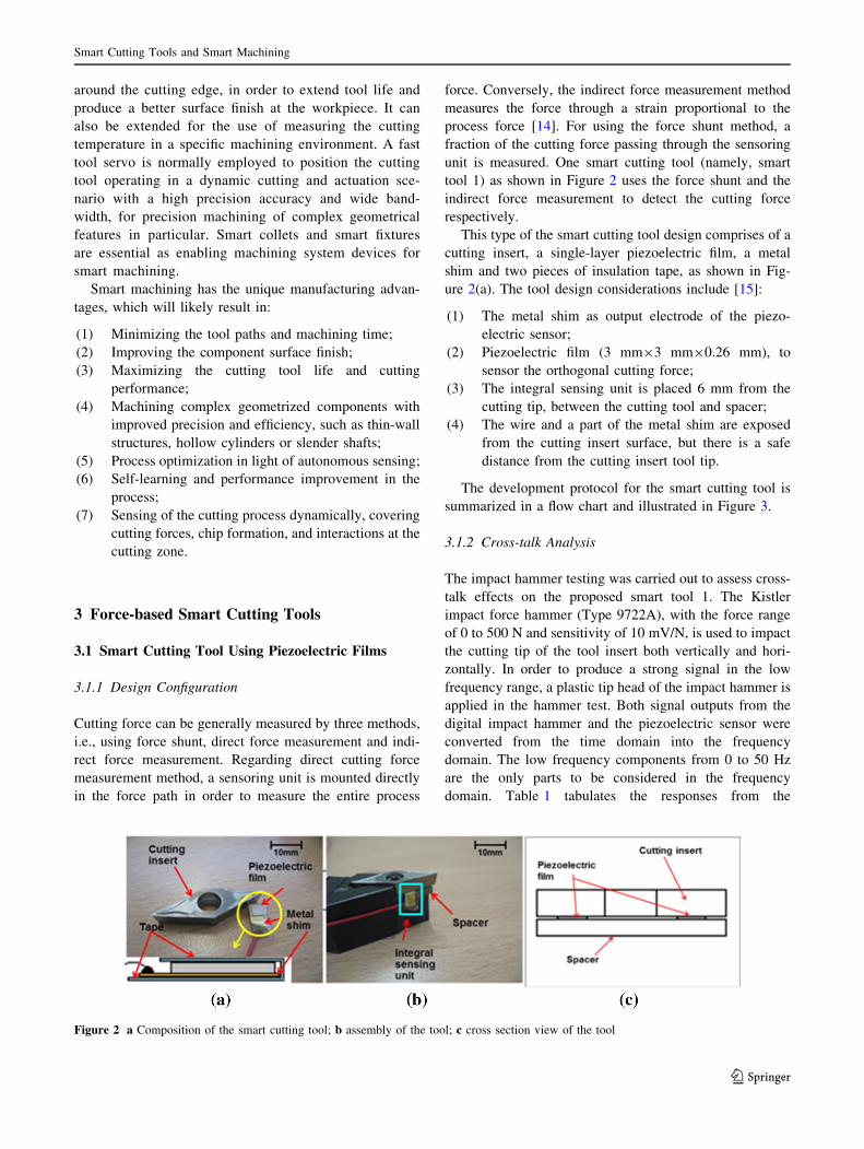
This type of the smart cutting tool design comprises of a
cutting insert, a single-layer piezoelectric film, a metal
shim and two pieces of insulation tape, as shown in Fig-
ure 2(a). The tool design considerations include [15]:
(1) The metal shim as output electrode of the piezo-
electric sensor;
(2) Piezoelectric film (3 mm93 mm90.26 mm), to
sensor the orthogonal cutting force;
(3) The integral sensing unit is placed 6 mm from the
cutting tip, between the cutting tool and spacer;
(4) The wire and a part of the metal shim are exposed
from the cutting insert surface, but there is a safe
distance from the cutting insert tool tip.
The development protocol for the smart cutting tool is
summarized in a flow chart and illustrated in Figure 3.
3.1.2 Cross-talk Analysis
The impact hammer testing was carried out to assess cross-
talk effects on the proposed smart tool 1. The Kistler
impact force hammer (Type 9722A), with the force range
of 0 to 500 N and sensitivity of 10 mV/N, is used to impact
the cutting tip of the tool insert both vertically and hori-
zontally. In order to produce a strong signal in the low
frequency range, a plastic tip head of the impact hammer is
applied in the hammer test. Both signal outputs from the
digital impact hammer and the piezoelectric sensor were
converted from the time domain into the frequency
domain. The low frequency components from 0 to 50 Hz
are the only parts to be considered in the frequency
domain. Table 1 tabulates the responses from the
Figure 2 a Composition of the smart cutting tool; b assembly of the tool; c cross section view of the tool
Smart Cutting Tools and Smart Machining
123
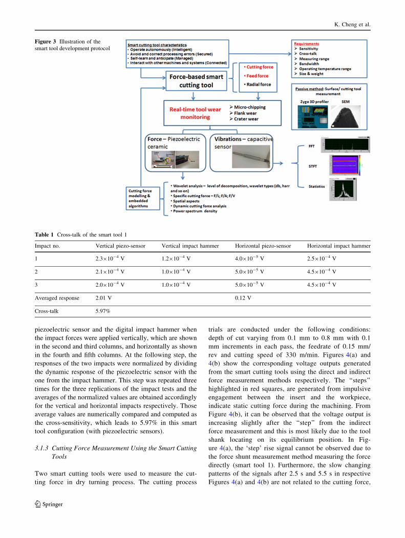
piezoelectric sensor and the digital impact hammer when
the impact forces were applied vertically, which are shown
in the second and third columns, and horizontally as shown
in the fourth and fifth columns. At the following step, the
responses of the two impacts were normalized by dividing
the dynamic response of the piezoelectric sensor with the
one from the impact hammer. This step was repeated three
times for the three replications of the impact tests and the
averages of the normalized values are obtained accordingly
for the vertical and horizontal impacts respectively. Those
average values are numerically compared and computed as
the cross-sensitivity, which leads to 5.97% in this smart
tool configuration (with piezoelectric sensors).
3.1.3 Cutting Force Measurement Using the Smart Cutting
Tools
Two smart cutting tools were used to measure the cut-
ting force in dry turning process. The cutting process
trials are conducted under the following conditions:
depth of cut varying from 0.1 mm to 0.8 mm with 0.1
mm increments in each pass, the feedrate of 0.15 mm/
rev and cutting speed of 330 m/min. Figures 4(a) and
4(b) show the corresponding voltage outputs generated
from the smart cutting tools using the direct and indirect
force measurement methods respectively. The ‘‘steps’’
highlighted in red squares, are generated from impulsive
engagement between the insert and the workpiece,
indicate static cutting force during the machining. From
Figure 4(b), it can be observed that the voltage output is
increasing slightly after the ‘‘step’’ from the indirect
force measurement and this is most likely due to the tool
shank locating on its equilibrium position. In Fig-
ure 4(a), the ‘step’ rise signal cannot be observed due to
the force shunt measurement method measuring the force
directly (smart tool 1). Furthermore, the slow changing
patterns of the signals after 2.5 s and 5.5 s in respective
Figures 4(a) and 4(b) are not related to the cutting force,
Figure 3 Illustration of the
smart tool development protocol
Table 1 Cross-talk of the smart tool 1
Impact no. Vertical piezo-sensor Vertical impact hammer Horizontal piezo-sensor Horizontal impact hammer
1 2.3910-4 V 1.2910-4 V 4.0910-5 V 2.5910-4 V
2 2.1910-4 V 1.0910-4 V 5.0910-5 V 4.5910-4 V
3 2.0910-4 V 1.0910-4 V 5.0910-5 V 4.5910-4 V
Averaged response 2.01 V 0.12 V
Cross-talk 5.97%
K. Cheng et al.
123
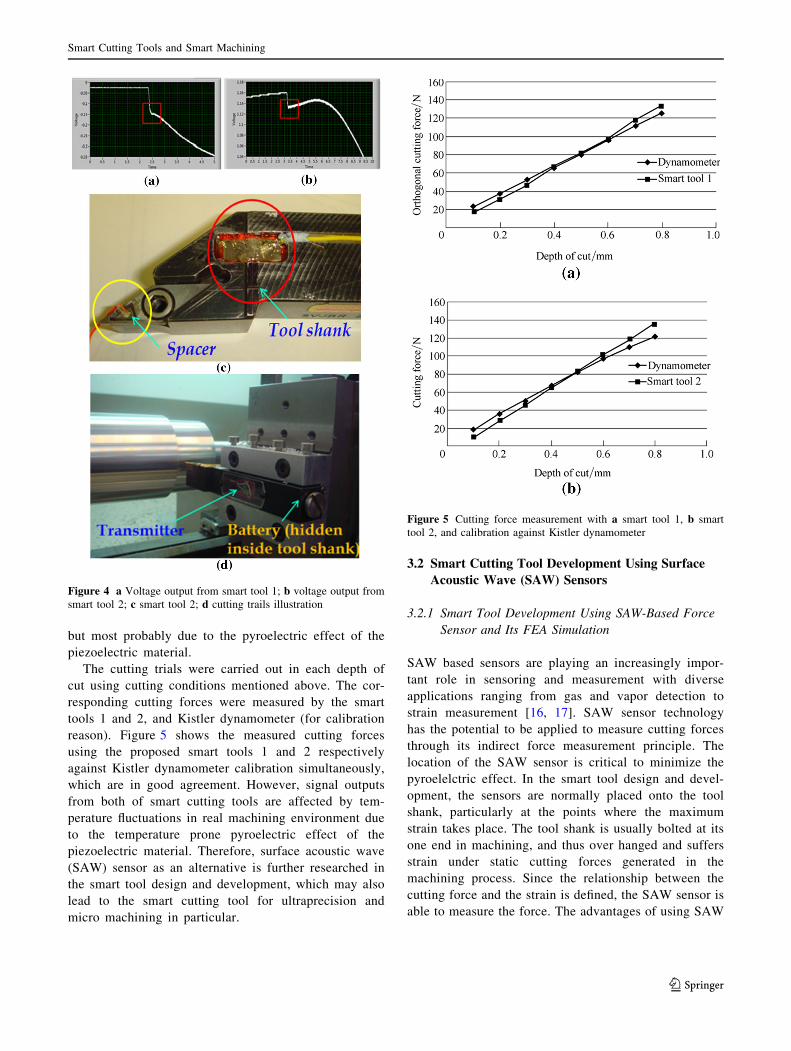
but most probably due to the pyroelectric effect of the
piezoelectric material.
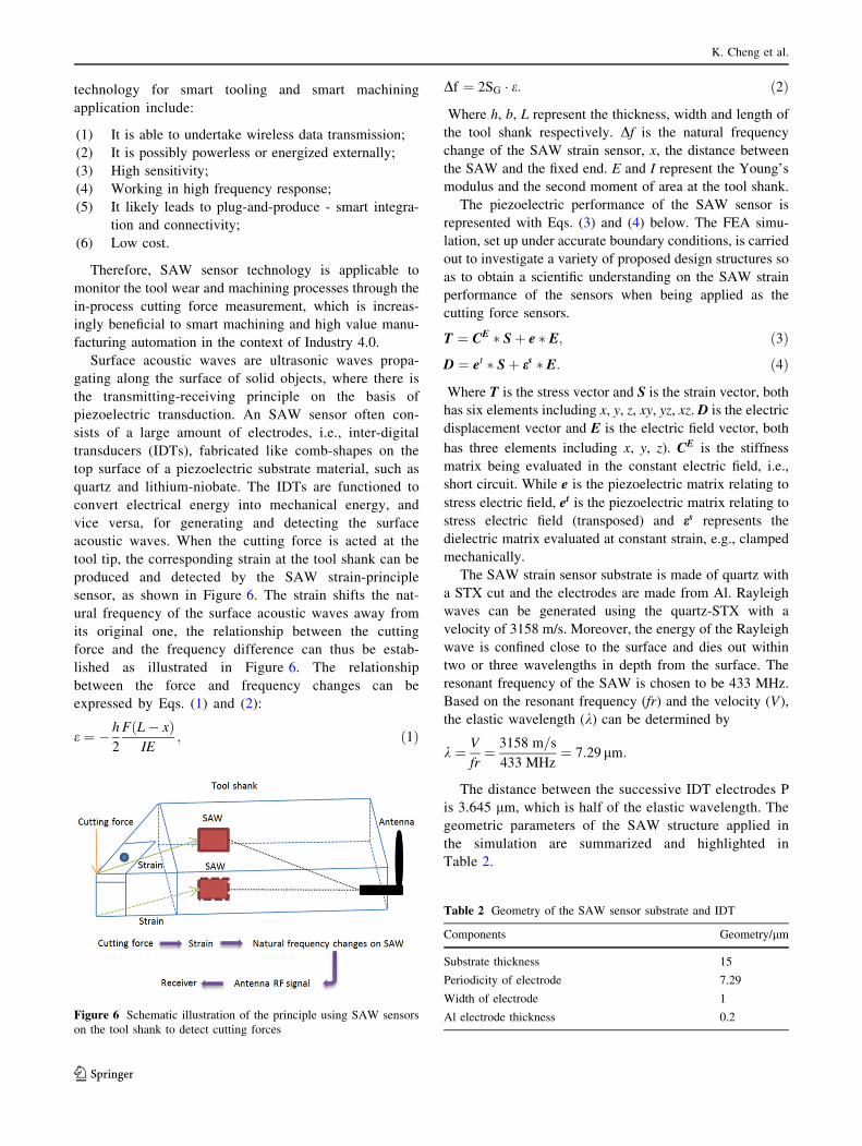
The cutting trials were carried out in each depth of
cut using cutting conditions mentioned above. The cor-
responding cutting forces were measured by the smart
tools 1 and 2, and Kistler dynamometer (for calibration
reason). Figure 5 shows the measured cutting forces
using the proposed smart tools 1 and 2 respectively
against Kistler dynamometer calibration simultaneously,
which are in good agreement. However, signal outputs
from both of smart cutting tools are affected by tem-
perature fluctuations in real machining environment due
to the temperature prone pyroelectric effect of the
piezoelectric material. Therefore, surface acoustic wave
(SAW) sensor as an alternative is further researched in
the smart tool design and development, which may also
lead to the smart cutting tool for ultraprecision and
micro machining in particular.
3.2 Smart Cutting Tool Development Using Surface
Acoustic Wave (SAW) Sensors
3.2.1 Smart Tool Development Using SAW-Based Force
Sensor and Its FEA Simulation
SAW based sensors are playing an increasingly impor-
tant role in sensoring and measurement with diverse
applications ranging from gas and vapor detection to
strain measurement [16, 17]. SAW sensor technology
has the potential to be applied to measure cutting forces
through its indirect force measurement principle. The
location of the SAW sensor is critical to minimize the
pyroelelctric effect. In the smart tool design and devel-
opment, the sensors are normally placed onto the tool
shank, particularly at the points where the maximum
strain takes place. The tool shank is usually bolted at its
one end in machining, and thus over hanged and suffers
strain under static cutting forces generated in the
machining process. Since the relationship between the
cutting force and the strain is defined, the SAW sensor is
able to measure the force. The advantages of using SAW
Figure 4 a Voltage output from smart tool 1; b voltage output from
smart tool 2; c smart tool 2; d cutting trails illustration
Figure 5 Cutting force measurement with a smart tool 1, b smart
tool 2, and calibration against Kistler dynamometer
Smart Cutting Tools and Smart Machining
123
technology for smart tooling and smart machining
application include:
(1) It is able to undertake wireless data transmission;
(2) It is possibly powerless or energized externally;
(3) High sensitivity;
(4) Working in high frequency response;
(5) It likely leads to plug-and-produce - smart integra-
tion and connectivity;
(6) Low cost.
Therefore, SAW sensor technology is applicable to
monitor the tool wear and machining processes through the
in-process cutting force measurement, which is increas-
ingly beneficial to smart machining and high value manu-
facturing automation in the context of Industry 4.0.
Surface acoustic waves are ultrasonic waves propa-
gating along the surface of solid objects, where there is
the transmitting-receiving principle on the basis of
piezoelectric transduction. An SAW sensor often con-
sists of a large amount of electrodes, i.e., inter-digital
transducers (IDTs), fabricated like comb-shapes on the
top surface of a piezoelectric substrate material, such as
quartz and lithium-niobate. The IDTs are functioned to
convert electrical energy into mechanical energy, and
vice versa, for generating and detecting the surface
acoustic waves. When the cutting force is acted at the
tool tip, the corresponding strain at the tool shank can be
produced and detected by the SAW strain-principle
sensor, as shown in Figure 6. The strain shifts the nat-
ural frequency of the surface acoustic waves away from
its original one, the relationship between the cutting
force and the frequency difference can thus be estab-
lished as illustrated in Figure 6. The relationship
between the force and frequency changes can be
expressed by Eqs. (1) and (2):
e ¼ � h
2
FðL� xÞIE
; ð1Þ
Df ¼ 2SG � e: ð2Þ
Where h, b, L represent the thickness, width and length of
the tool shank respectively. Df is the natural frequency
change of the SAW strain sensor, x, the distance between
the SAW and the fixed end. E and I represent the Young’s
modulus and the second moment of area at the tool shank.
The piezoelectric performance of the SAW sensor is
represented with Eqs. (3) and (4) below. The FEA simu-
lation, set up under accurate boundary conditions, is carried
out to investigate a variety of proposed design structures so
as to obtain a scientific understanding on the SAW strain
performance of the sensors when being applied as the
cutting force sensors.
T ¼ CE � Sþ e � E; ð3Þ
D ¼ et � Sþ es � E: ð4Þ
Where T is the stress vector and S is the strain vector, both
has six elements including x, y, z, xy, yz, xz. D is the electric
displacement vector and E is the electric field vector, both
has three elements including x, y, z). CE is the stiffness
matrix being evaluated in the constant electric field, i.e.,
short circuit. While e is the piezoelectric matrix relating to
stress electric field, et is the piezoelectric matrix relating to
stress electric field (transposed) and es represents the
dielectric matrix evaluated at constant strain, e.g., clamped
mechanically.
The SAW strain sensor substrate is made of quartz with
a STX cut and the electrodes are made from Al. Rayleigh
waves can be generated using the quartz-STX with a
velocity of 3158 m/s. Moreover, the energy of the Rayleigh
wave is confined close to the surface and dies out within
two or three wavelengths in depth from the surface. The
resonant frequency of the SAW is chosen to be 433 MHz.
Based on the resonant frequency (fr) and the velocity (V),
the elastic wavelength (k) can be determined by
k ¼ V
fr¼ 3158 m=s
433 MHz¼ 7:29 lm:
The distance between the successive IDT electrodes P
is 3.645 lm, which is half of the elastic wavelength. The
geometric parameters of the SAW structure applied in
the simulation are summarized and highlighted in
Table 2.
Figure 6 Schematic illustration of the principle using SAW sensors
on the tool shank to detect cutting forces
Table 2 Geometry of the SAW sensor substrate and IDT
Components Geometry/lm
Substrate thickness 15
Periodicity of electrode 7.29
Width of electrode 1
Al electrode thickness 0.2
K. Cheng et al.
123

In developing FEA simulation for the SAW strain sen-
sor, the boundary conditions for the simulation, as shown
in Figure 7, need to be defined accurately. The material
properties for both the piezoelectric substrate and the Al
electrodes should be defined accurately as well. The stiff-
ness matrix, the piezoelectric matrix, and the permittivity
matrix are required as inputs into the FEA simulation.
Young’s modulus, the Poisson’s ratio and the density are
essential data as the inputs for the Al electrodes. The modal
analysis is carried out to determine the modal frequencies
and corresponding mode shapes so as to choose the proper
propagation wave mode travelling along the substrate. The
simulation can also be used as the starting point for further
harmonic analysis to find out the corresponding dynamic
response in the frequency components of interest. The
modal analysis is performed to show several mode shapes
and modal frequencies. The 8th mode shape and its cor-
responding modal frequency of 465 MHz are found to be
the preferred propagation wave mode as shown in Figure 8,
since the wave only propagates near the surface and
maximally penetrates about 1.2k below the surface. This
agrees with the Rayleigh waves theory [18].
In the harmonic analysis, an AC voltage of 10 V is
applied onto one electrode, with a range of frequencies
from 464 MHz to 472 MHz around the modal frequency
obtained in the previous analysis. The resonant peak is
obtained in the modal frequency of 465 MHz with a
dynamic response of 0.16 lm as shown in Figure 9. The
Figure 7 Boundary conditions defining the propagation for the FEA
simulations
Figure 8 The 8th mode shape at 465 MHz and other modes for the SAW sensors
Smart Cutting Tools and Smart Machining
123
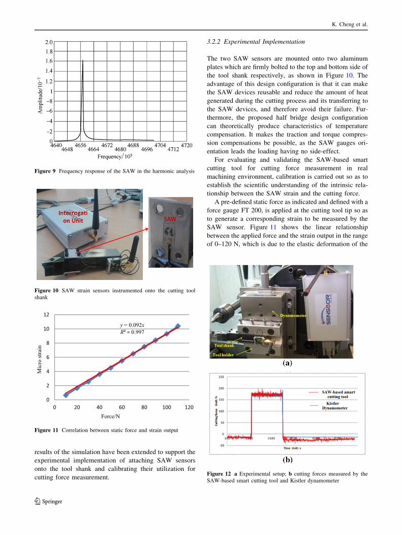
results of the simulation have been extended to support the
experimental implementation of attaching SAW sensors
onto the tool shank and calibrating their utilization for
cutting force measurement.
3.2.2 Experimental Implementation
The two SAW sensors are mounted onto two aluminum
plates which are firmly bolted to the top and bottom side of
the tool shank respectively, as shown in Figure 10. The
advantage of this design configuration is that it can make
the SAW devices reusable and reduce the amount of heat
generated during the cutting process and its transferring to
the SAW devices, and therefore avoid their failure. Fur-
thermore, the proposed half bridge design configuration
can theoretically produce characteristics of temperature
compensation. It makes the traction and torque compres-
sion compensations be possible, as the SAW gauges ori-
entation leads the loading having no side-effect.
For evaluating and validating the SAW-based smart
cutting tool for cutting force measurement in real
machining environment, calibration is carried out so as to
establish the scientific understanding of the intrinsic rela-
tionship between the SAW strain and the cutting force.
A pre-defined static force as indicated and defined with a
force gauge FT 200, is applied at the cutting tool tip so as
to generate a corresponding strain to be measured by the
SAW sensor. Figure 11 shows the linear relationship
between the applied force and the strain output in the range
of 0–120 N, which is due to the elastic deformation of the
Figure 9 Frequency response of the SAW in the harmonic analysis
Figure 10 SAW strain sensors instrumented onto the cutting tool
shank
y = 0.092xR² = 0.997
0
2
4
6
8
10
12
0 20 40 60 80 100 120
Mic
ro st
rain
Force/N
Figure 11 Correlation between static force and strain output
Figure 12 a Experimental setup; b cutting forces measured by the
SAW-based smart cutting tool and Kistler dynamometer
K. Cheng et al.
123
tool shank [19]. The curve fitting also leads to the
expression equation for representing the relationship
between the applied force and the strain, with a consider-
ably high correlation, i.e., R2 value of 0.9968.
3.2.3 Preliminary Machining Trials
The SAW-based smart cutting tool is used to determine the
cutting force in dry turning process, in the machining
conditions: the depth of cut, 1 mm, constant federate at 0.2
mm/r, and a spindle speed at 900 r/min. Figure 12(a) shows
the experimental setup with the tool shank mounted on top
of the Kistler dynamometer and the interrogation unit
communicating with the SAW-based smart cutting tool.
Figure 12(b) shows the comparison of the cutting force
measurement results by using the SAW-based smart tool
and the Kistler dynamometer. The signal pattern captured
by the smart cutting tool is in good agreement with the one
by Kistler dynamometer.
4 Design of Cutting Temperature-based SmartCutting Tools
The increase in cutting temperature normally causes the
premature cutting tool failure or excessive tool wear, while
most of the wear processes occurs at the major flank face
and rake face of the cutting tool. There are four main wear
mechanisms in association with tool failure, including:
oxidation, abrasion, adhesion and diffusion. All of these
wears are related to the temperature sensitivity even under
normal cutting conditions [20, 21]. At low cutting tem-
perature (due to soft cutting or high cooling efficiency),
adhesive and abrasive wears are dominant. While the cut-
ting temperature is higher than a certain threshold, thermal
induced wear, such as oxidation and diffusion, are acti-
vated and dominate total wear. The utilization of cutting
fluid, traditionally applied to remove heat generated from
the cutting process, can additionally cause environmental
pollution, health hazards, surface contamination and an
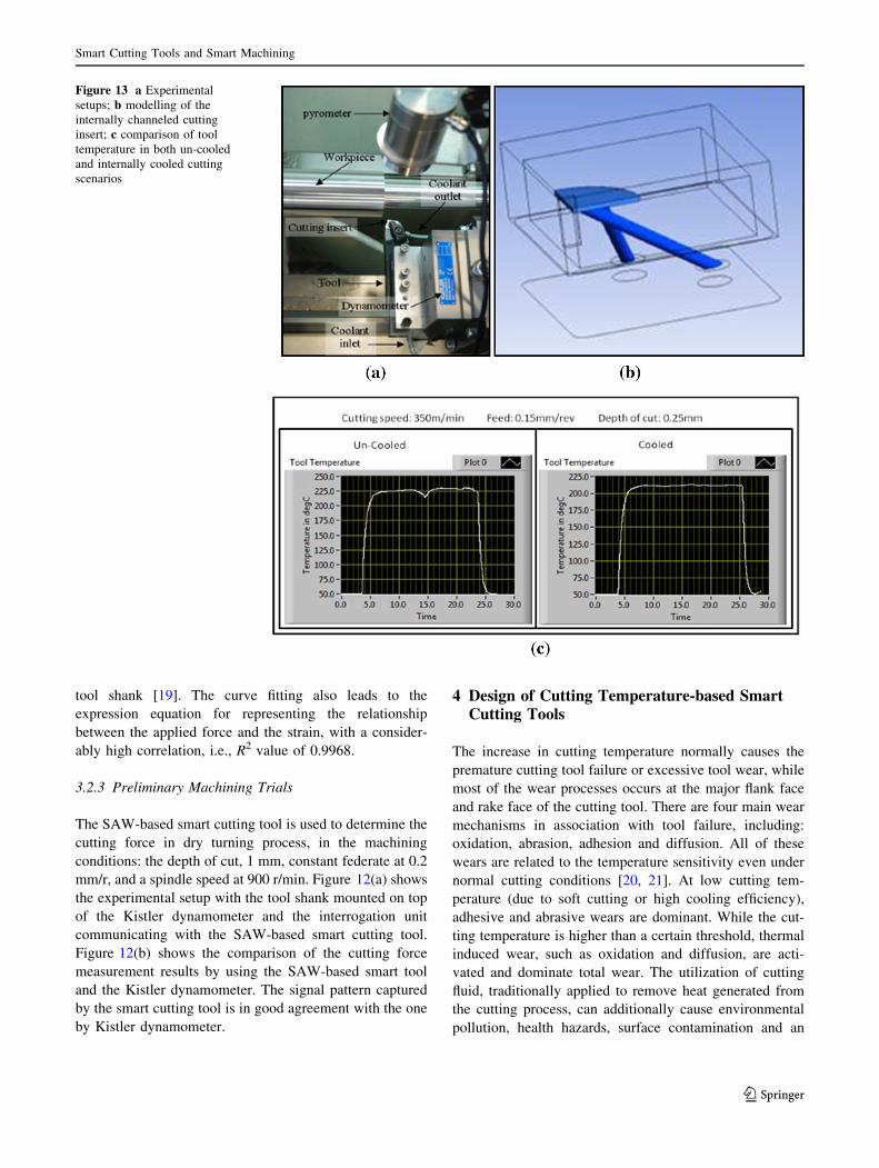
Figure 13 a Experimental
setups; b modelling of the
internally channeled cutting
insert; c comparison of tool
temperature in both un-cooled
and internally cooled cutting
scenarios
Smart Cutting Tools and Smart Machining
123
increased cost of production [22]. The above issues can be
avoided by using an internally-cooled smart cutting tool.
Figure 13(a) shows the experimental setup, a pyrometer
for measuring the temperature at the cutting tip and the
Kistler dynamometer for measuring the cutting force in
three directions during dry machining of the aluminum
workpiece using an internally-cooled smart cutting tool
developed by authors. As shown in Figure 13(b), at the
internally-cooled cutting tool, micro-channels (coolant
inlet and outlet) are machined within the solid cutting
insert, which are close to the cutting tip where the maxi-
mum heat being generated. The micro-channels are
designed to achieve optimal cooling performance, while
maintaining the sufficient mechanical strength of the cut-
ting tool. Pure water, functioning as the cooling fluid, is
pumped through micro-channels to reduce the temperature
near the cutting tip. The tool temperature reaches 225 �C in
machining the aluminum workpiece (cutting speed: 350
m/min; feedrate: 0.15 mm/rev and depth of cut: 0.25 mm).
However, the temperature drops to 210 �C (Figure 13(c))
when the internal coolant is applied. It is possible to
maintain the tool within a ‘safe’ cutting temperature range
by using such a smart tool. As discussed above, the cutting
temperature affects the tool wear albeit the observed total
wear is not necessarily linked with the cutting temperature
in all cases. The cutting trials results indicate that using the
internally-cooled smart cutting tool can reduce the cutting
temperature and activation of adhesion, oxidation and
diffusion wears; and lead to an optimum cutting tempera-
ture which can minimize tool wears development.
Although more experimentation and machining trials
need to be undertaken for further validation, internally-
cooled smart cutting tools can be applied in the following
applications:
(1) Adaptive smart machining of high value
components;
(2) Contamination-free machining such as medical
devices and explosive materials;
(3) Machining of difficult-to-machine materials includ-
ing titanium, magnesium and Inconel alloys, etc.
5 Fast Tool Servos (FTS)
Fast tool servos (FTS) play an important role in precision
turning of micro-featured or free-form surfaces with a
diamond cutting tool. The FTS system normally includes a
piezoelectric (or voice coils) actuator, flexure hinges, and
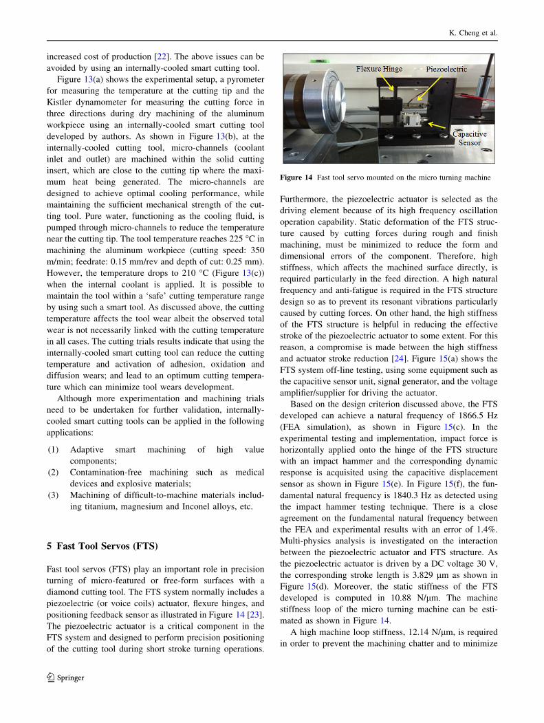
positioning feedback sensor as illustrated in Figure 14 [23].
The piezoelectric actuator is a critical component in the
FTS system and designed to perform precision positioning
of the cutting tool during short stroke turning operations.
Furthermore, the piezoelectric actuator is selected as the
driving element because of its high frequency oscillation
operation capability. Static deformation of the FTS struc-
ture caused by cutting forces during rough and finish
machining, must be minimized to reduce the form and
dimensional errors of the component. Therefore, high
stiffness, which affects the machined surface directly, is
required particularly in the feed direction. A high natural
frequency and anti-fatigue is required in the FTS structure
design so as to prevent its resonant vibrations particularly
caused by cutting forces. On other hand, the high stiffness
of the FTS structure is helpful in reducing the effective
stroke of the piezoelectric actuator to some extent. For this
reason, a compromise is made between the high stiffness
and actuator stroke reduction [24]. Figure 15(a) shows the
FTS system off-line testing, using some equipment such as
the capacitive sensor unit, signal generator, and the voltage
amplifier/supplier for driving the actuator.
Based on the design criterion discussed above, the FTS
developed can achieve a natural frequency of 1866.5 Hz
(FEA simulation), as shown in Figure 15(c). In the
experimental testing and implementation, impact force is
horizontally applied onto the hinge of the FTS structure
with an impact hammer and the corresponding dynamic
response is acquisited using the capacitive displacement
sensor as shown in Figure 15(e). In Figure 15(f), the fun-
damental natural frequency is 1840.3 Hz as detected using
the impact hammer testing technique. There is a close
agreement on the fundamental natural frequency between
the FEA and experimental results with an error of 1.4%.
Multi-physics analysis is investigated on the interaction
between the piezoelectric actuator and FTS structure. As
the piezoelectric actuator is driven by a DC voltage 30 V,
the corresponding stroke length is 3.829 lm as shown in
Figure 15(d). Moreover, the static stiffness of the FTS
developed is computed in 10.88 N/lm. The machine
stiffness loop of the micro turning machine can be esti-
mated as shown in Figure 14.
A high machine loop stiffness, 12.14 N/lm, is required
in order to prevent the machining chatter and to minimize
Figure 14 Fast tool servo mounted on the micro turning machine
K. Cheng et al.
123
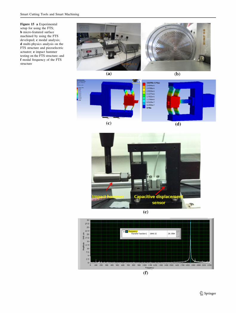
Figure 15 a Experimental
setup for using the FTS;
b micro-featured surface
machined by using the FTS
developed; c modal analysis;
d multi-physics analysis on the
FTS structure and piezoelectric
actuator; e impact hammer
testing on the FTS structure; and
f modal frequency of the FTS
structure
Smart Cutting Tools and Smart Machining
123
the geometric error of the component. The detailed analysis
is as follows:
(1) Axial stiffness of the spindle: Kspinlde = 40.00 N/lm(2) Lateral stiffness of the air bearing slide: KX_Slide_Z =
40.00 N/lm(3) Axial stiffness of the tool holder: KTool_holder =
KFlexure ? KPiezo= 10.88 N/lm ? 20.00 N/lm=30.88
N/lm
Therefore, the total machine loop stiffness is
1=KTotal loop ¼ 1=Kspinlde þ 1=KX Slide Z þ 1=KTool holder
) KTotal loop ¼ 12:14N/lm
Preliminary cutting trials are carried out for machining
micro-featured surface pattern on an Al workpiece using
the FTS in the face turning process shown in Figure 15(b).
The FTS can be considered as one type of smart tool
systems to position the tool precisely and dynamically,
which is essential for machining micro-structured surfaces
and special-featured components.
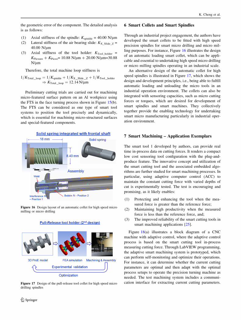
6 Smart Collets and Smart Spindles
Through an industrial project engagement, the authors have
developed the smart collets to be fitted with high speed
precision spindles for smart micro drilling and micro mil-
ling purposes. For instance, Figure 16 illustrates the design
of an automatic loading smart collet, which can be appli-
cable and essential to undertaking high speed micro drilling
or micro milling spindles operating in an industrial scale.
An alternative design of the automatic collet for high
speed spindles is illustrated in Figure 17, which shows the
design and development principles, i.e., being able to fulfill
automatic loading and unloading the micro tools in an
industrial operation environment. The collets can also be
integrated with sensoring capacities, such as micro cutting
forces or torques, which are desired for development of
smart spindles and smart machines. They collectively
together provide the enabling technology for undertaking
smart micro manufacturing particularly in industrial oper-
ation environment.
7 Smart Machining – Application Exemplars
The smart tool 1 developed by authors, can provide real
time in-process data on cutting forces. It renders a compact
low cost sensoring tool configuration with the plug-and-
produce feature. The innovative concept and utilization of
the smart cutting tool and the associated embedded algo-
rithms are further studied for smart machining processes. In
particular, using adaptive computer control (ACC) to
maintain the constant cutting force with varied depths of
cut is experimentally tested. The test is encouraging and
promising, as it likely enables:
(1) Protecting and enhancing the tool when the mea-
sured force is greater than the reference force;
(2) Maintaining high productivity when the measured
force is less than the reference force, and;
(3) The improved reliability of the smart cutting tools in
smart machining applications [25].
Figure 18(a) illustrates a block diagram of a CNC
machine with adaptive control, where the adaptive control
process is based on the smart cutting tool in-process
measuring cutting force. Through LabVIEW programming,
the adaptive smart machining system is prototyped, which
can perform self-monitoring and optimize their operations.
For instance, it can determine whether the current cutting
parameters are optimal and then adapt with the optimal
process setups to operate the precision turning machine as
needed. The test machining system includes a communi-
cation interface for extracting current cutting parameters.
Figure 16 Design layout of an automatic collet for high speed micro
milling or micro drilling
Figure 17 Design of the pull-release tool collet for high speed micro
drilling spindles
K. Cheng et al.
123
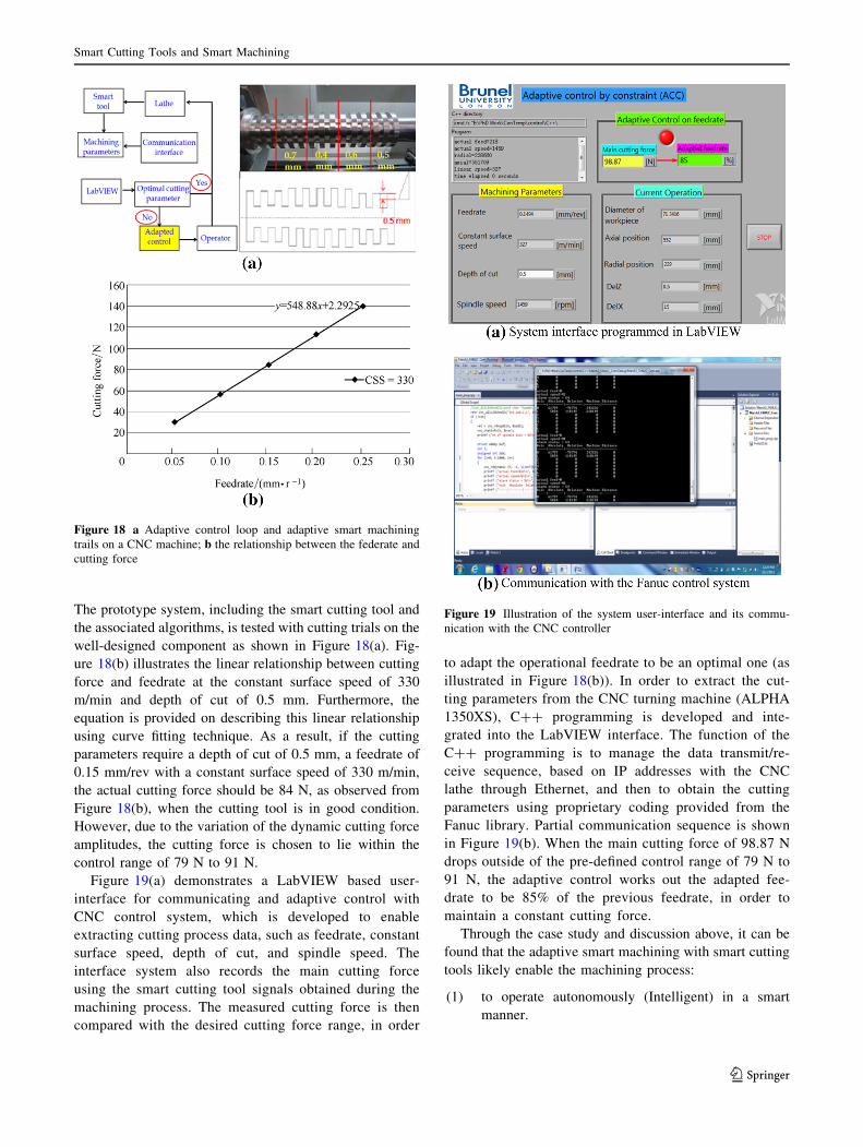
The prototype system, including the smart cutting tool and
the associated algorithms, is tested with cutting trials on the
well-designed component as shown in Figure 18(a). Fig-
ure 18(b) illustrates the linear relationship between cutting
force and feedrate at the constant surface speed of 330
m/min and depth of cut of 0.5 mm. Furthermore, the
equation is provided on describing this linear relationship
using curve fitting technique. As a result, if the cutting
parameters require a depth of cut of 0.5 mm, a feedrate of
0.15 mm/rev with a constant surface speed of 330 m/min,
the actual cutting force should be 84 N, as observed from
Figure 18(b), when the cutting tool is in good condition.
However, due to the variation of the dynamic cutting force
amplitudes, the cutting force is chosen to lie within the
control range of 79 N to 91 N.
Figure 19(a) demonstrates a LabVIEW based user-
interface for communicating and adaptive control with
CNC control system, which is developed to enable
extracting cutting process data, such as feedrate, constant
surface speed, depth of cut, and spindle speed. The
interface system also records the main cutting force
using the smart cutting tool signals obtained during the
machining process. The measured cutting force is then
compared with the desired cutting force range, in order
to adapt the operational feedrate to be an optimal one (as
illustrated in Figure 18(b)). In order to extract the cut-
ting parameters from the CNC turning machine (ALPHA
1350XS), C?? programming is developed and inte-
grated into the LabVIEW interface. The function of the
C?? programming is to manage the data transmit/re-
ceive sequence, based on IP addresses with the CNC
lathe through Ethernet, and then to obtain the cutting
parameters using proprietary coding provided from the
Fanuc library. Partial communication sequence is shown
in Figure 19(b). When the main cutting force of 98.87 N
drops outside of the pre-defined control range of 79 N to
91 N, the adaptive control works out the adapted fee-
drate to be 85% of the previous feedrate, in order to
maintain a constant cutting force.
Through the case study and discussion above, it can be
found that the adaptive smart machining with smart cutting
tools likely enable the machining process:
(1) to operate autonomously (Intelligent) in a smart
manner.
Figure 18 a Adaptive control loop and adaptive smart machining
trails on a CNC machine; b the relationship between the federate and
cutting force
Figure 19 Illustration of the system user-interface and its commu-
nication with the CNC controller
Smart Cutting Tools and Smart Machining
123
(2) to avoid and correct processing errors in process
(Secured).
(3) to self-learn from the real-time data and anticipate
the dynamic changes (Managed).
(4) to interact with other machines and systems (Con-
nected), while operating on the shop-floor manufac-
turing cell and system.
ISMC (Intelligent, Secured, Managed and Connected)
represents the essential features of smart machining pro-
cesses enabled by smart toolings (smart cutting tools, smart
collets and smart fixtures, etc.). ISMC is the essential and
dispensable design rules and fundamentals in developing
smart toolings and adaptive smart machining systems.
8 Conclusions
A number of smart tools, including cutting force-based
smart cutting tools, cutting temperature-based tools, FTS
and smart collets/fixtures are presented in this paper. The
design concepts of the force-based smart cutting tools are
proposed using the piezoelectric film based on the force
shunt measurement and the indirect force measurement
methods. With the depth of cut from 0.1 mm to 0.8 mm, a
close agreement on the orthogonal cutting force measure-
ment can be achieved by using Kistler dynamometer and
the two respective smart cutting tools developed. In order
to achieve higher accuracy and more reliable measurement,
SAW-based smart tooling development is exploited with
the application to ultraprecision machining. Based on
modelling and simulation analysis, a better understanding
of SAW-based sensors is obtained and used to optimize the
practical design of the SAW-based smart cutting tool. The
experimental results from machining trials show close
agreement between the Kistler dynamometer and the
SAW-based smart cutting tool on the main cutting force
measurement. The preliminary cutting trials using the
internally cooled smart cutting tool have demonstrated the
temperature of the cutting tip can be reduced by pumping
the coolant through internal micro-channels within the
smart cutting tool. Smart collets are also presented in line
with requirements for smart spindles and high precision
micro drilling and milling application. Further in-depth
research for the internally cooled cutting tool is carried out
particularly on its applications in adaptive machining. In
the final part of this paper, one of the presented smart tools
was used in smart machining by using adaptive control to
maintain the cutting force constant with varied depths of
cut by adapting the federate, which can be used particularly
in machining components made from hybrid materials or
hybrid structures, such as composite-aluminum-titanium
structures, in aerospace industry.
This paper presents the smart cutting tools which act as
the essential interface devices between smart machine tools
and smart machining processes. The smart tooling can also
be extended into smart fixtures and jigs, which are indis-
pensable parts of smart machining systems particularly
applicable in the context of Industry 4.0 and beyond [26].
Acknowledgements The authors gratefully acknowledge the com-
mitted support of all the technical staff of the AMEE Department at
Brunel University London. Particular gratitude is expressed to Dr
Saiful Anwar Bin Che Ghani, Dr Hui Ding and Mr Paul Yates.
Open Access This article is distributed under the terms of the
Creative Commons Attribution 4.0 International License (http://crea
tivecommons.org/licenses/by/4.0/), which permits unrestricted use,
distribution, and reproduction in any medium, provided you give
appropriate credit to the original author(s) and the source, provide a
link to the Creative Commons license, and indicate if changes were
made.
References
1. J B Hentz, V K Nguyen, W Maeder, et al. An enabling digital
foundation towards smart machining. 8th CIRP Conference on
Intelligent Computation in Manufacturing Engineering, 2013, 12:
240–245.
2. G W Vogl, M A Donmez, A Archenti. Diagnostics for geometric
performance of machine tool linear axes. CIRP Annals - Manu-
facturing Technology, 2016, 65(1): 377–380.
3. B Peukert, S Benecke, J Clavell, et al. Addressing sustainability
and flexibility in manufacturing via smart modular machine tool
frames to support sustainable value creation. The 22nd CIRP
Conference on Life Cycle Engineering, 2015, 29: 514–519.
4. M Fujishima, M Mori, K Nishimura, et al. Study on quality
improvement of machine tools. The 5th International Conference
on Through-life Engineering Services (TESConf 2016), 2017, 59:
156–159.
5. C Prinz, F Morlock, S Freith, et al. Learning factory modules for
smart factories in Industrie 4.0. 6th CIRP Conference on Learn-
ing Factories, 2016, 54: 113–118.
6. K Cheng, D H Huo. Micro Cutting: Fundamentals and Appli-
cations. John Wiley & Sons Ltd, Chichester, October 2013.
7. J Tlusty, G Andrews. A critical review of sensors for unmanned
machining. Annals of the CIRP, 1983, 32 (2): 611–622.
8. M Weck. Machine diagnostics in automated production. Manuf.
Syst, 1983, 2 (2): 101–106.
9. R Teti, K Jemielniak, G O’Donnell, et al. Advanced monitoring
of machining operations. CIRP Annals - Manufacturing Tech-
nology, 2010, 59: 717–739.
10. K Cheng. Machining Dynamics: Theory, Applications and
Practices. Springer, London, 2008.
11. J L Stein, K Huh. Monitoring cutting forces in turning: A model:
Base approach. Manuf. Sci. Eng., Trans. ASME. 2002, 124:
27–31.
12. W Sawangsri, K Cheng. An innovative approach to cutting force
modelling in diamond turning and its correlation analysis with
tool wear. Proc. IMechE, Part B J. of Engineering Manufacture,
2016, 230(3): 405–415.
13. C Ferri, T Minton, K Cheng, et al. Internally cooled tools and
cutting temperature in contamination-free machining. Proc.
IMechE, Part C: J. of Mechanical Engineering Science, 2014,
228(1): 135–145.
K. Cheng et al.
123
14. T Kim, J Kim. Adaptive cutting force control for a machining
center by using indirect cutting force measurements. Interna-
tional Journal of Machine Tools & Manufacture, 1995, 36:
925–937.
15. C Wang, R Rakowski, K Cheng. Design and analysis of a
piezoelectric film embedded smart cutting tool. Proc. IMechE,
Part B: J. Engineering Manufacture, 2013, 227: 254-260.
16. P Alfred. A review of wireless SAW sensors. IEEE Transactions
on Ultrasonics, Ferroelectrics, and Frequency Control, 2000, 47:
317–322.
17. H Moussa, C Andrew, W Wojtek. Acoustic wave sensors: design,
sensing mechanisms and applications. Smart Mater. Struct, 1997,
6: 647–657.
18. M Hofer. Finite-element simulation of wave propagation in
periodic piezoelectric SAW structures. IEEE Transactions on
Ultrasonics, Ferroelectrics, and Frequency Control, 2006, 53:
1192–1201.
19. B Donohoe, D Geraghty, G E O’Donnell. Wireless calibration of
a surface acoustic wave resonator as a strain sensor. IEEE Sen-
sors Journal, 2011, 11: 1026–1032.
20. E M Trent, P K Wright. Metal cutting. 4th ed. Butterworth-
Heinemann, Woburn Massachusetts, July 2000.
21. A Saiful. Design and analysis of the internally cooled smart
cutting tools with the applications to adaptive machining. PhD
Thesis, Brunel University, 2013.
22. X Sun, R Bateman, K Cheng, et al. Design and analysis of an
internally cooled smart cutting tool for dry cutting. Proc. IMechE,
Part B: J. Engineering Manufacture, 2011, 226: 585–591.
23. H Li, R Ibrahim, K Cheng. Design of an innovative compliant
fast tool servo for precision engineering. Mech. Sci, 2011, 2:
139–146.
24. D H Huo, K Cheng. A dynamics-driven approach to the design of
precision machine tools for micro-manufacturing and its imple-
mentation perspectives. Proc. IMechE, Part B: J. Engineering
Manufacture, 2008, 222: 1–13.
25. C Wang, K Cheng, R Rawkoski. Cutting force based analysis and
correlative observations on the tool wear in diamond turning of
single-crystal silicon. IMechE, Part B: J. Engineering Manufac-
ture, 2015, 229(10): 1867–1873.
26. K Cheng. Keynote presentation - 2: Smart tooling, smart
machines and smart manufacturing: Working towards the
Industry 4.0 and beyond. IEEE International Conference on
Automation and Computing (ICAC2015), Glasgow, UK,
September 2015.
Kai Cheng, born in December 1961, is currently a Chair Professor
and Theme Leader in Ultraprecision and Micro/Nano Manufacturing
at Brunel University London, United Kingdom. Professor Cheng is a
Fellow of the IMechE and IET since 2004. His current research
interests include ultraprecision and micro machining, design of smart
tooling and smart machining, multiscale multi-physics based design
and analysis, and sustainable manufacturing systems. Tel: ?44
(0)1895-267255; E-mail: [email protected].
Zhi-Chao Niu, born in September 1990, is currently a PhD candidate
in Ultraprecision and Micro/Nano Manufacturing Theme at Brunel
University London, United Kingdom. He received his master degree
on Advanced Engineering Design from Brunel University London.
His research interests include ultraprecision and micro machining,
micro cutting mechanics, and composite materials machining. Tel:
?44(0)7743844131; E-mail: [email protected].
Robin C. Wang, is currently a research fellow at Brunel University
London, United Kingdom. His current research interests include smart
cutting tools, design of air-bearings, and smart machining. E-mail:
Richard Rakowski, is currently a senior lecturer at Brunel University
London, United Kingdom. His current research focuses on smart
cutting tools, manufacturing metrology, and creative engineering
design. E-mail: [email protected].
Richard Bateman, is currently a lecturer at Brunel University
London, United Kingdom. His main research interests include energy-
smart manufacturing, digital and e-manufacturing. E-mail:
Smart Cutting Tools and Smart Machining
123