smart diffusers - web.tools4revit.comweb.tools4revit.com/smart-diffusers/files/smart diffuser...
TRANSCRIPT
Smart Diffusers
How to work with diffusers and other Revit® MEP elements easily

Working with MEP elements Smart Diffusers extension
• …extension allows adding to families an unlimited number of engineering parametric
equations which define relations between main HVAC parameters like Pressure Drop,
Sound Power Level, Air Flow, Velocity, Throw, Duct Diameter, Free area and other;
•...calculates the number of Air Terminals required in the space;
•...defines the number of Air Terminals on the basis of calculation results and other
conditions;
•...finds optimal type of Air Terminals;
•...automatically updates n-dimensional parameters for all Air Terminals and accessories
(fittings) in the project;
•...includes smart families of diffusers, grilles and dampers as examples how to build
intelligent MEP objects;
Smart Diffusers
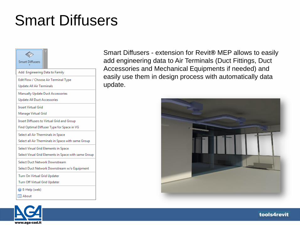
Smart Diffusers - extension for Revit® MEP allows to easily
add engineering data to Air Terminals (Duct Fittings, Duct
Accessories and Mechanical Equipments if needed) and
easily use them in design process with automatically data
update.

Smart Diffusers
Smart Diffusers Tool has the E-Help where users can find
sample Metric projects:

Smart Diffusers Add Engineering Data to Family
Tool adds engineering data to a
selected family.
Function works with Air Terminal, Duct
Accessory, Mechanical Equipment,
Duct Fitting categories.
Configuration – allows selecting of
configuration modes with described
relations and priorities. Read more on page
5.
Family types – types of selected family
where parameter values will be added.
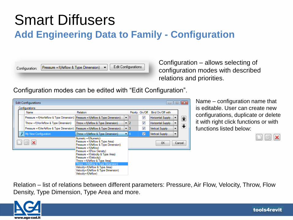
Smart Diffusers Add Engineering Data to Family - Configuration
Configuration – allows selecting of
configuration modes with described
relations and priorities.
Configuration modes can be edited with “Edit Configuration”.
Relation – list of relations between different parameters: Pressure, Air Flow, Velocity, Throw, Flow
Density, Type Dimension, Type Area and more.
Name – configuration name that
is editable. User can create new
configurations, duplicate or delete
it with right click functions or with
functions listed below:

Smart Diffusers Add Engineering Data to Family - Configuration
Priority is used for parameters calculation
in predefined way. Calculation results go
from one graph to another by priority –
step by step from graph with the highest
priority to graphs with lower priorities.
Priority can be changed with “Up” and
“Down” arrows.
Smart Diffusers Add Engineering Data to Family - Configuration
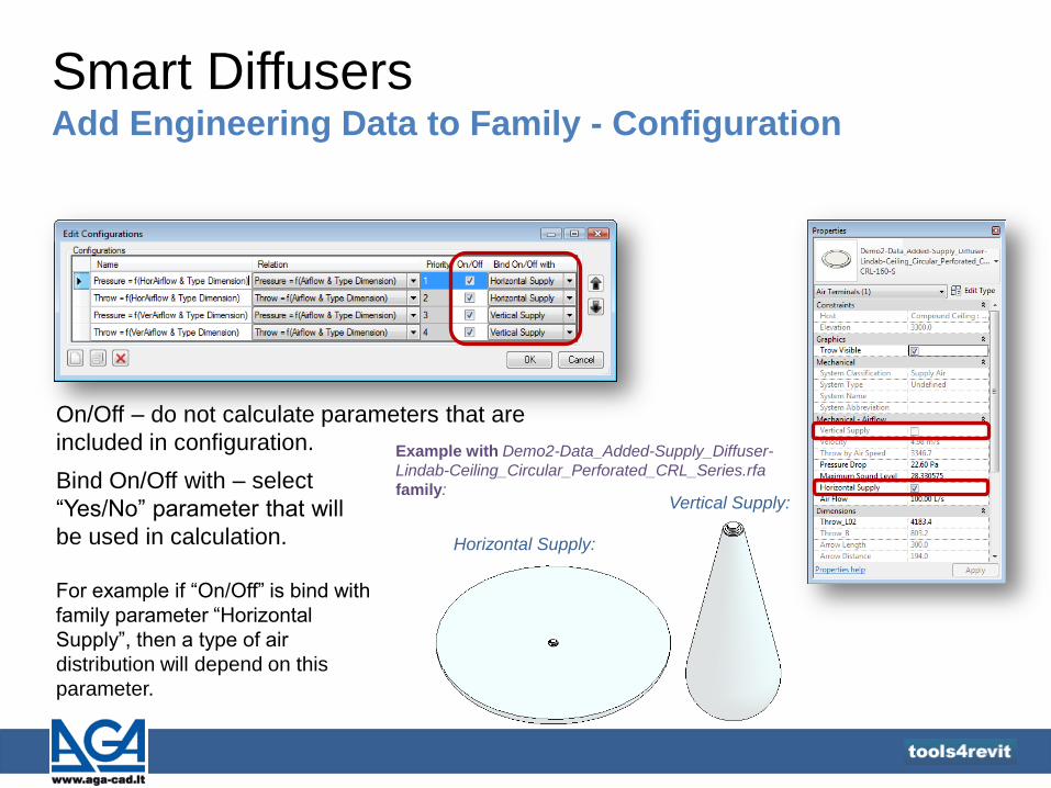
On/Off – do not calculate parameters that are
included in configuration.
Horizontal Supply:
Vertical Supply: Bind On/Off with – select
“Yes/No” parameter that will
be used in calculation.
For example if “On/Off” is bind with
family parameter “Horizontal
Supply”, then a type of air
distribution will depend on this
parameter.
Example with Demo2-Data_Added-Supply_Diffuser-
Lindab-Ceiling_Circular_Perforated_CRL_Series.rfa
family:

Smart Diffusers Add Engineering Data to Family - Images
Load Image – loads images with a chart from a file
that will appear in Chart Image Window. Images formats: JPG, JPEG, GIF, BMP, PNG.
Paste - images can be pasted from clipboard with
original dimensions.
If dimensions of the picture are bigger than 400x267
pixels , the borders of the picture will be cut. If
dimensions of the picture is smaller than 400x267
pixels, the picture will be centered in Chart Image
Window.
Paste and Resize – the same as Paste, just with
picture resizing.

Smart Diffusers Add Engineering Data to Family - Images
As an example - image can be easily pasted from opened
pdf file after command Edit → Take a Snapshot:

Smart Diffusers Add Engineering Data to Family
1st position – value depends on the configuration
and goes for Y axis in the chart. In the example configuration is “Pressure = f (Airflow &
Type Dimension)”. The 1st position is Pressure. For the
“Pressure” user has to select family instance parameter
with “Pressure” type. This parameter will be used in
calculation.
2nd position – value depends on the configuration
and goes for X axis in the chart. In the example configuration is “Pressure = f (Airflow &
Type Dimension)”. The 2st position is Air Flow. For the
“Air Flow” user has to select family instance parameter
with “Air Flow” type. This parameter will be used in
calculation.
Unit Type – select unit types for Y and X axes.
Unit types must be the same as in the chart (not
in family or project).

Smart Diffusers Add Engineering Data to Family
Logarithmic scale - select these options if X or Y
axes scale of measurement uses the logarithm
of a physical quantity instead of the quantity
itself.
If logarithmic scale has to be switched off, then it
goes like a linear scale.

Smart Diffusers Add Engineering Data to Family
Pick left bottom corner –
select a point in the left
bottom corner of a graph. See point indicated as “1”.
Pick right top corner –
select a point in the right top
corner of a graph. See point indicated as “2”.

Smart Diffusers Add Engineering Data to Family
1st position – name depends on the
configuration and value goes for minimum
rate on X axis of the chart.
2nd position – name depends on the
configuration and value goes for maximum
rate on X axis of the chart.
3rd position – name depends on the
configuration and value goes for minimum
rate on Y axis of the chart.
In the example
configuration is “Pressure
= f (Airflow & Type
Dimension)”. The 1st and
2nd positions are “Air Flow”
and the 3rd and 4th are
“Pressure”.
4th position – name depends on the
configuration and value goes for maximum rate
on Y axis of the chart.

Smart Diffusers Add Engineering Data to Family
Pick line start point – pick a point at the
beginning of the line for corresponding type. For example, if diffuser type is “LCA-100-S”, then
pick a point indicated as “1”. It can be picked at
any place of the line.
Pick line end point – pick a point at the end
of the line for corresponding type. For example, if diffuser type is “LCA-100-S”, then
pick a point indicated as “2”. It can be picked at
any place of the line.
For every type pick corresponding points on the lines
from the chart if “Calculate parameters for each type” is
selected.
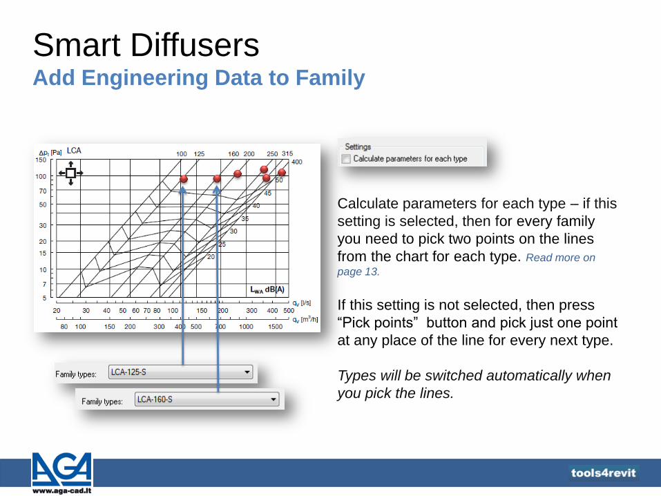
Smart Diffusers Add Engineering Data to Family
Calculate parameters for each type – if this
setting is selected, then for every family
you need to pick two points on the lines
from the chart for each type. Read more on
page 13.
If this setting is not selected, then press
“Pick points” button and pick just one point
at any place of the line for every next type.
Types will be switched automatically when
you pick the lines.
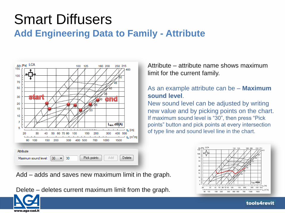
Smart Diffusers Add Engineering Data to Family - Attribute
Attribute – attribute name shows maximum
limit for the current family.
As an example attribute can be – Maximum
sound level.
New sound level can be adjusted by writing
new value and by picking points on the chart. If maximum sound level is “30”, then press “Pick
points” button and pick points at every intersection
of type line and sound level line in the chart.
Add – adds and saves new maximum limit in the graph.
Delete – deletes current maximum limit from the graph.
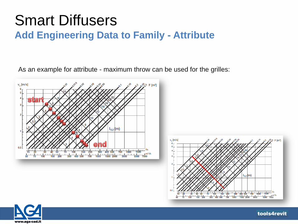
Smart Diffusers Add Engineering Data to Family - Attribute
As an example for attribute - maximum throw can be used for the grilles:

Smart Diffusers Add Engineering Data to Family
Create relation with – select parameter which is criterion for
making different types in the family. This criterion has to be
included in configuration.
Parameter has to be created like “Type”.
Value – shows the value of selected parameter for each type.
Unit Type – shows unit type of preselected parameter

Smart Diffusers Add Engineering Data to Family
Use separate image for
each type – select this
setting in case if each type
has different graph.
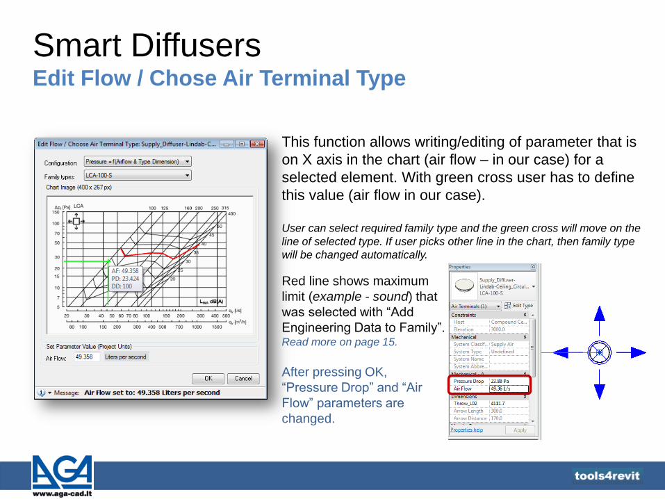
Smart Diffusers Edit Flow / Chose Air Terminal Type
This function allows writing/editing of parameter that is
on X axis in the chart (air flow – in our case) for a
selected element. With green cross user has to define
this value (air flow in our case).
User can select required family type and the green cross will move on the
line of selected type. If user picks other line in the chart, then family type
will be changed automatically.
Red line shows maximum
limit (example - sound) that
was selected with “Add
Engineering Data to Family”. Read more on page 15.
After pressing OK,
“Pressure Drop” and “Air
Flow” parameters are
changed.

Smart Diffusers Throw parameter
Our created example families of air terminals have at least two dimensional relations.
For example, diffusers have a graph with the second priority where air jet throw was used.
Graph for throw specifies the throw
l0.2 [m] at an average terminal
velocity for 0.2 m/s.

Smart Diffusers Throw parameter
Our created “Throw_L02” instance parameter in the family shows boundaries of throw value
from the chart. Round 2D circles show air jet dispersal based on throw parameters.
For Grilles:
For Diffusers with
horizontal air supply:
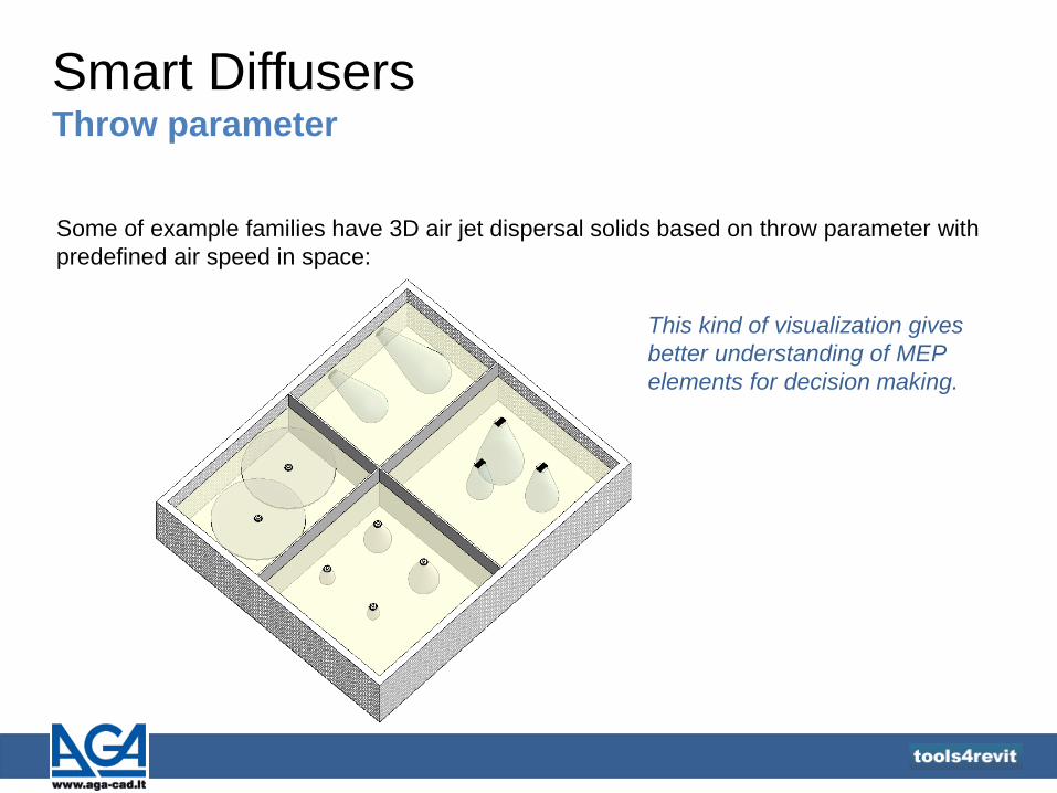
Smart Diffusers Throw parameter
Some of example families have 3D air jet dispersal solids based on throw parameter with
predefined air speed in space:
This kind of visualization gives
better understanding of MEP
elements for decision making.

Smart Diffusers Manually Update Duct Accessories
Manually Updates Duct Accessories - updates parameters (used in configuration) for a
selected element. Dialog shows created configuration modes and charts.
All this information comes from “Add Engineering Data to Family”. Read more on pages 4-18.
Functions work with Duct
Accessory, Mechanical
Equipment, Duct Fitting
categories.
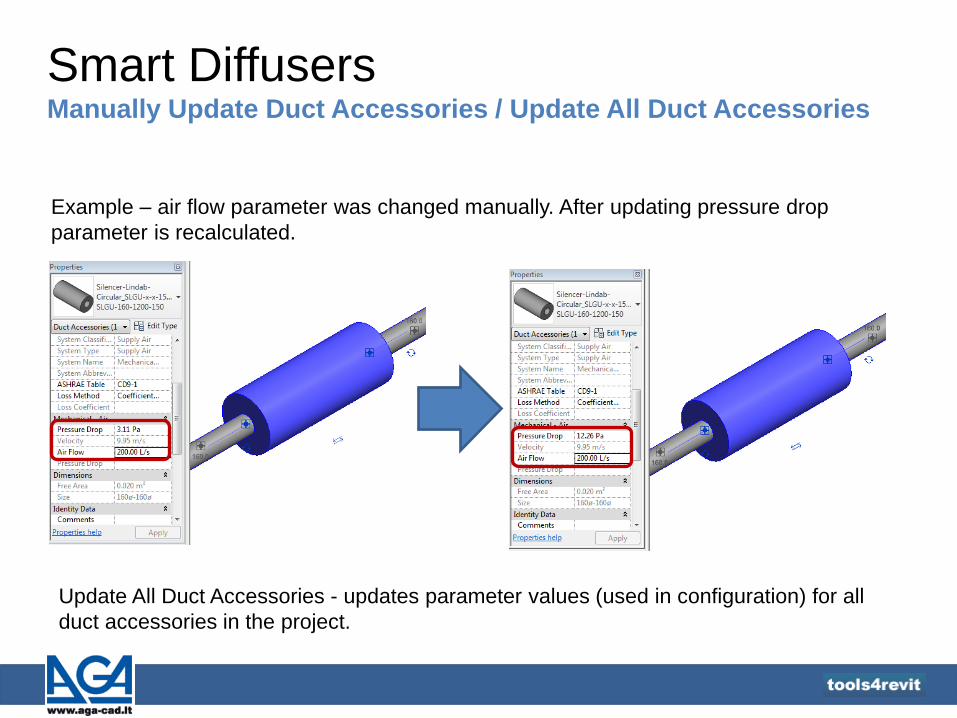
Smart Diffusers Manually Update Duct Accessories / Update All Duct Accessories
Example – air flow parameter was changed manually. After updating pressure drop
parameter is recalculated.
Update All Duct Accessories - updates parameter values (used in configuration) for all
duct accessories in the project.

Smart Diffusers Manually Update Duct Accessories - example
Example with “Actionair” duct damper where pressure drop depends on velocity is included.
The second graph in this family
calculates sound level.
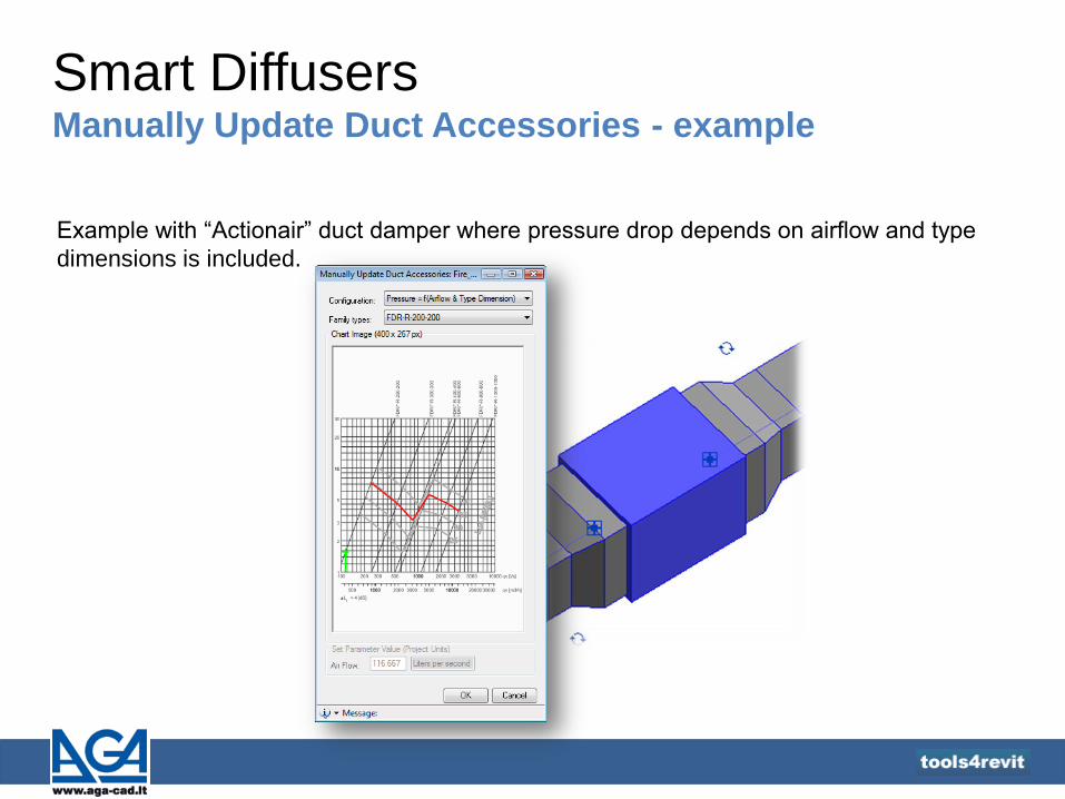
Smart Diffusers Manually Update Duct Accessories - example
Example with “Actionair” duct damper where pressure drop depends on airflow and type
dimensions is included.
Smart Diffusers Update All Air Terminals
Update All Air Terminal – updates parameter values (Pressure Drop, Air Flow, Velocity,
Throw, Flow Density, Type Dimension, Type Area and more) for all air terminals in the
project which are not in hidden groups.
This function remembers all configurations (read more on pages 5-6) and priorities for every air
terminal.
For hidden groups user has to make a decision manually with “Find Optimal Air Terminal
Type for Spaces” tool. Read more on page 20.

Smart Diffusers Insert/Manage Virtual Grid
Insert Virtual Grid – inserts virtual grid for inserting elements in
the space with different boundaries.
Steps to insert the virtual grid:
1. Select space or element in the space. Boundaries and
parameters of selected space will be used;
2. Select a wall for detecting X direction.
Placement parameters
can be locked

Smart Diffusers Insert/Manage Virtual Grid
Length (X Direction) – maximum length of X direction in space;
Width (Y Direction) – maximum length of Y direction in space;
Select Base Wall for X Direction – select a wall from the
project for detecting other X direction.
Selected wall

Smart Diffusers Insert/Manage Virtual Grid
Elevation - elevation of virtual grid element where air
terminals will be inserted;
Throw – value of our created “Throw_L02” instance parameter
in the virtual grid family shows boundaries of throw value.
Green round 2D circles show air jet dispersal based on throw
parameters;
Calculation Elevation – air speed calculation elevation in
space by standard methodology;
Calculated Throw – red round 2D circles show air jet dispersal
based on calculated throw parameter.

Smart Diffusers Insert/Manage Virtual Grid
Real Number of Elements – real number of elements that
are inserted in the current space with its shape;
Distance X, Distance Y – distance between virtual grid
elements in X and Y direction. These values will be used
when “Distribute by Spacing” parameter will be selected;
Number in X Direction, Number in Y
Direction – number of virtual grid elements in
X and Y directions.
Smart Diffusers Insert/Manage Virtual Grid
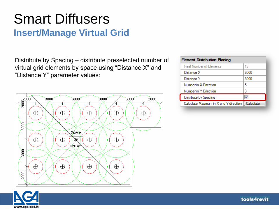
Distribute by Spacing – distribute preselected number of
virtual grid elements by space using “Distance X” and
“Distance Y” parameter values:
Smart Diffusers Insert/Manage Virtual Grid
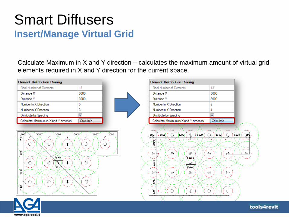
Calculate Maximum in X and Y direction – calculates the maximum amount of virtual grid
elements required in X and Y direction for the current space.

Smart Diffusers Insert/Manage Virtual Grid
Offset from Original in X/Y Direction – virtual grid will be
moved with offset from the beginning in X, Y direction. If
these values are zero, then virtual grid elements will be
centered in the space.
Distances between first and last
virtual grid elements in the space
can be checked near “Elements
Distances from Start/End”.

Smart Diffusers Insert/Manage Virtual Grid
For example there are two
virtual grid elements in X and
Y direction in the current
space. Distance from the
faces of walls has to be
smaller than the distance
between virtual grids. If
“Distance Round to” is set to
600, then the distance
between virtual grids is
rounded to the number
divided from 600.
Distance Round to – rounds the distance between virtual grid elements.
Smart Diffusers Insert/Manage Virtual Grid
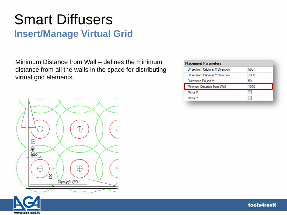
Minimum Distance from Wall – defines the minimum
distance from all the walls in the space for distributing
virtual grid elements.

Smart Diffusers Insert/Manage Virtual Grid
Mirror X, Mirror Y – mirrors
virtual grid in X and Y
directions.

Smart Diffusers Insert Diffusers to Virtual Grid and Group
Inserts selected diffuser type to selected virtual grid in the project.

Smart Diffusers Find Optimal Air Terminal Type for Spaces in VG
Tool calculates the number of air terminals of predefined
type according to the space parameters. It can also find the
optimal air terminal type by selected number of terminals.
Red line shows predefined maximum limit - maximum sound
level in our case. Read more on page 15.
Blue line shows supply airflow in the space to which air
terminals belongs.
Green line shows X (air flow in our case) and Y (pressure in
our case) of current air terminal type.
Smart Diffusers Find Optimal Air Terminal Type for Spaces in VG
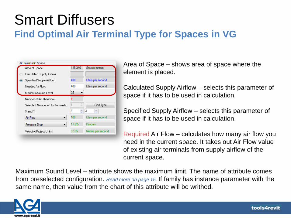
Area of Space – shows area of space where the
element is placed.
Calculated Supply Airflow – selects this parameter of
space if it has to be used in calculation.
Specified Supply Airflow – selects this parameter of
space if it has to be used in calculation.
Required Air Flow – calculates how many air flow you
need in the current space. It takes out Air Flow value
of existing air terminals from supply airflow of the
current space.
Maximum Sound Level – attribute shows the maximum limit. The name of attribute comes
from preselected configuration. Read more on page 15. If family has instance parameter with the
same name, then value from the chart of this attribute will be writhed.

Smart Diffusers Find Optimal Air Terminal Type for Spaces in VG
Number of Air Terminals – calculated number of air
terminals for selected space.
Selected Number of Air Terminals – rounded number of air
terminals. This number can be changed when user does
not use virtual grid in the space.
Find Type – finds optimal type of air terminals by selected
number of air terminals.
X and Y – number of air terminals in X and Y direction
located on virtual grid.
Air Flow – calculated air flow value for one terminal.
Pressure Drop – calculated pressure value from the chart. The name of this parameter comes
from preselected configuration. Read more on page 9.
Velocity – velocity in the air terminal duct connection, calculated by formula: Air Flow/Duct Area
(Free Area).
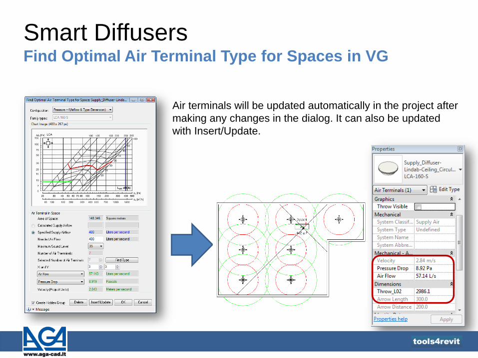
Smart Diffusers Find Optimal Air Terminal Type for Spaces in VG
Air terminals will be updated automatically in the project after
making any changes in the dialog. It can also be updated
with Insert/Update.
Smart Diffusers Find Optimal Air Terminal Type for Spaces in VG
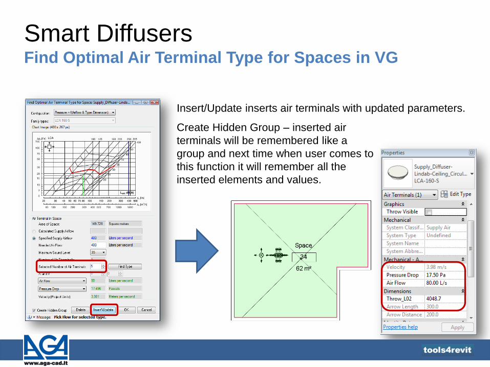
Insert/Update inserts air terminals with updated parameters.
Create Hidden Group – inserted air
terminals will be remembered like a
group and next time when user comes to
this function it will remember all the
inserted elements and values.

Smart Diffusers Turn On/Off Virtual Grid Updater
Turn On/Off Virtual grid Updater – virtual grid can be updated automatically while making
changes in the model if virtual grid updater is turned on.
After moving
the wall:
Updater is turned on
Updater is turned off

Smart Diffusers Other Examples
Example – “Halton” ceiling supply diffusers can have 1, 2, 3 or 4-way patterns with
corresponding charts:

Smart Diffusers Results
• …extension allows to add to families unlimited number of engineering parametric
equations which define relations between main HVAC parameters like Pressure Drop,
Sound Power Level, Air Flow, Velocity, Throw, Duct Diameter, Free area and other;
•...calculates the number of Air Terminals required in the space;
•...defines the number of Air Terminals on the basis of calculation results and other
conditions;
•...finds optimal type of Air Terminals;
•...automatically updates n-dimensional parameters for all Air Terminals and accessories
(fittings) in the project;
•...includes smart families of diffusers, grilles and dampers as examples how to build
intelligent MEP objects;

Copyright © 2012 AGA CAD Ltd.
TOOLS4REVIT© is developed by AGA CAD Ltd., Autodesk Authorised Developer
to
ols4
revit
Address: AGA CAD Ltd. Žalgirio g. 112A, LT-09300 Vilnius, Lithuania, EU Contact: Phone: +370 5 2398111 Fax: +370 5 2398113 E-mail: [email protected] www.tools4revit.com
AGA-CAD is the supplier of computer-aided design software and data management solution, operating since 1991. Company’s activities consist of TOOLS4REVIT development, Revit® families creation, programming services for working with BIM projects faster and easier. With resellers in a number of countries AGA CAD Ltd. implements BIM solutions for architects, structural and MEP engineers, constructors and building contractors.
If you have any ideas or problems and you would like to make your work with BIM projects faster and easier, we can design a tool or a program especially for you. Write your ideas directly to [email protected].