smart do. - steel s.a. · pdf filethe new smart do digital measurement ... iec 61850-9-2 le...
TRANSCRIPT

smART DO.DIGITAL MEASUREMENT TECHNOLOGY.

Moving together
This document may be subject to changes. Contact ARTECHE to confi rm the characteristics and availability of the products described here.
3smART DO | Digital Measurement Technology
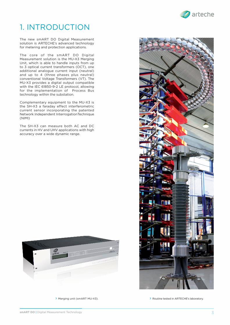
1. INTRODUCTIONThe new smART DO Digital Measurement solution is ARTECHE’s advanced technology for metering and protection applications.
The core of the smART DO Digital Measurement solution is the MU-X3 Merging Unit, which is able to handle inputs from up to 3 optical current transformers (OCT), one additional analogue current input (neutral) and up to 4 (three phases plus neutral) conventional Voltage Transformers (VT). The MU-X3 provides a digital output compatible with the IEC 61850-9-2 LE protocol, allowing for the implementation of Process Bus technology within the substation.
Complementary equipment to the MU-X3 is the SH-X3 a faraday effect interferometric current sensor incorporating the patented Network Independent InterrogationTechnique (NIMI)
The SH-X3 can measure both AC and DC currents in HV and UHV applications with high accuracy over a wide dynamic range.
› Merging unit (smART MU-X3). › Routine tested in ARTECHE’s laboratory.

4 smART DO | Digital Measurement Technology
The operation of the smART DO OCT is based on the Faraday Eff ect. The polarization state of a linearly polarized optical signal is rotated as it travels through a magnetic fi eld.
For an optical signal which travels along a closed path, the angle of rotation is proportional to the current enclosed by the path.
The rotation of the polarization state of the light is measured interferometrically as the phase diff erence between circularly polarized optical signals which travel in opposite directions around a coil of fi bre that encloses the primary.
2. HOW THE OPTICAL TRANSFORMER WORKS
I
Elliptical polarization state
Rotation proportional to the electric field (phase shift of the E components)
E
Ex
Ey
Input lightpulse is divided in two andit passes alongthe SPOF indifferentdirections.
The two pulses returnto the coupler with anopposite polarizationrotation.Here the electric fieldsof the light are superposed.
Coupler 3x3
B
Sensing Fibre
B
E
Ex
Ey
FARADAY EFFECT INTERFEROMETER
Intensity
Current
P1 P3P2
5smART DO | Digital Measurement Technology
3. SYSTEM COMPONENTS
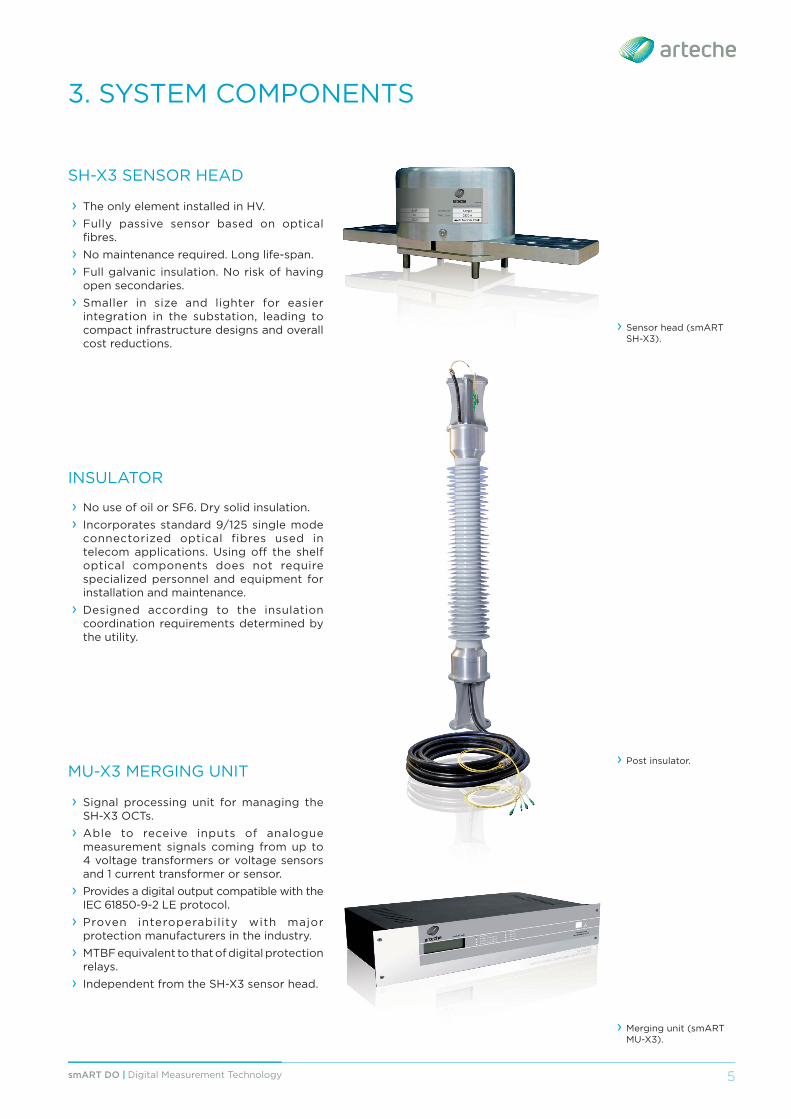
SH-X3 SENSOR HEAD
› The only element installed in HV. › Fully passive sensor based on optical fi bres.
› No maintenance required. Long life-span. › Full galvanic insulation. No risk of having open secondaries.
› Smaller in size and lighter for easier integration in the substation, leading to compact infrastructure designs and overall cost reductions.
INSULATOR
› No use of oil or SF6. Dry solid insulation. › Incorporates standard 9/125 single mode connectorized optical fibres used in telecom applications. Using off the shelf optical components does not require specialized personnel and equipment for installation and maintenance.
› Designed according to the insulation coordination requirements determined by the utility.
MU-X3 MERGING UNIT
› Signal processing unit for managing the SH-X3 OCTs.
› Able to receive inputs of analogue measurement signals coming from up to 4 voltage transformers or voltage sensors and 1 current transformer or sensor.
› Provides a digital output compatible with the IEC 61850-9-2 LE protocol.
› Proven interoperability with major protection manufacturers in the industry.
› MTBF equivalent to that of digital protection relays.
› Independent from the SH-X3 sensor head.
› Sensor head (smART SH-X3).
› Merging unit (smART MU-X3).
› Post insulator.
6 smART DO | Digital Measurement Technology
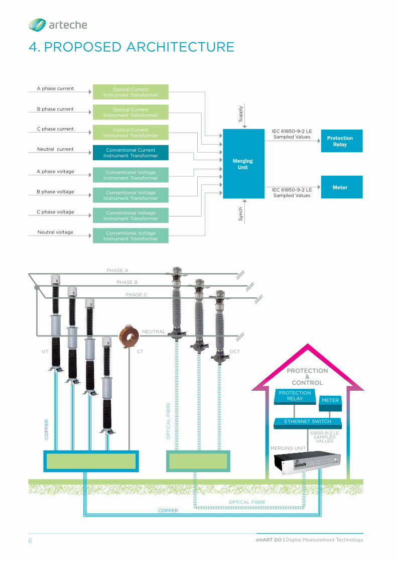
4. PROPOSED ARCHITECTURE
PHASE A
PHASE B
PHASE C
OCTVT
NEUTRAL
PROTECTION RELAY METER
ETHERNET SWITCH
CO
PP
ER
OP
TIC
AL
FIB
RE
COPPER
OPTICAL FIBRE
MERGING UNIT
61850-9-2 LESAMPLEDVALUES
PROTECTION&
CONTROL
A phase current
B phase current
C phase current
Neutral current
Optical Current Instrument Transformer
Optical Current Instrument Transformer
Optical Current Instrument Transformer
Conventional CurrentInstrument Transformer
Conventional VoltageInstrument Transformer
Conventional VoltageInstrument Transformer
Conventional VoltageInstrument Transformer
Conventional VoltageInstrument Transformer
Protection Relay
MeterIEC 61850-9-2 LE Sampled Values
IEC 61850-9-2 LE Sampled Values
A phase voltage
B phase voltage
C phase voltage
Neutral voltage
MergingUnit
Sup
ply
Syn
ch
CT

7smART DO | Digital Measurement Technology
5. MAIN BENEFITS OF USING OPTICAL SENSING AND DIGITAL MEASUREMENT TECHNOLOGIES
TECHNOLOGY: passive sensor based on optical fi bres, resulting in a long life time with no maintenance requirements. Not using magnetic cores eliminate saturation limitations. Digital output interface compatible with the IEC 61850-9-2 LE Process Bus protocol.
DESIGN: considerably smaller size and lighter weight for an easier integration in the substation, leading to compact infrastructure designs and overall cost reductions. Standardized common telecommunication duplex single mode optical fi bre is used for the connection between the sensor head and the merging unit, so that in-fi eld installation requirements can be fulfi lled by personnel having basic skills, regular components and tools.
PERFORMANCE: broad bandwidth, measuring both DC and AC currents (50-60 Hz) up to the 128th harmonic (at 256 samples per cycle) with high metering accuracy over an unlimited dynamic range.
APPLICABILITY: Universal Current Transformer. The utility will specify a single sensing device for the whole network that will be used both for metering and protection, in combination with the appropriate insulator according to the system’s voltage.
ENVIRONMENT: solid and dry insulation, avoiding the use of oil or SF6.
SAFETY: full galvanic insulation by default with no risk of having open secondary terminals or explosive failure modes.
BUDGET: cost reduction during commissioning and in operation.
PROCUREMENT: spare requirements would be reduced to a single optical sensor and normally no more than 3 or 4 types of insulators for the corresponding voltage levels existing in the grid, allowing for keeping a stock and considerably reducing lead times considerably.

8 smART DO | Digital Measurement Technology
6. TECHNICAL SPECIFICATIONS
SH-X3 SENSOR HEAD
PHYSICAL
Dimensions*
* Subject to change.
Weight 15 Kg.
IP IP66
Primary palm connection Aluminum
Optical connectors 2xSC/APC
ELECTRICAL
Metering accuracy IEC Class 0.2/0.2s
Nominal current range Standard: 100 – 5,000 Amps AC
ENVIROMENTAL
Operating temperature range-40ºC / +85ºC
Storage temperature range
Operating humidity range100%
Storage humidity range
ø258
224
570
50
50 140
25
9smART DO | Digital Measurement Technology
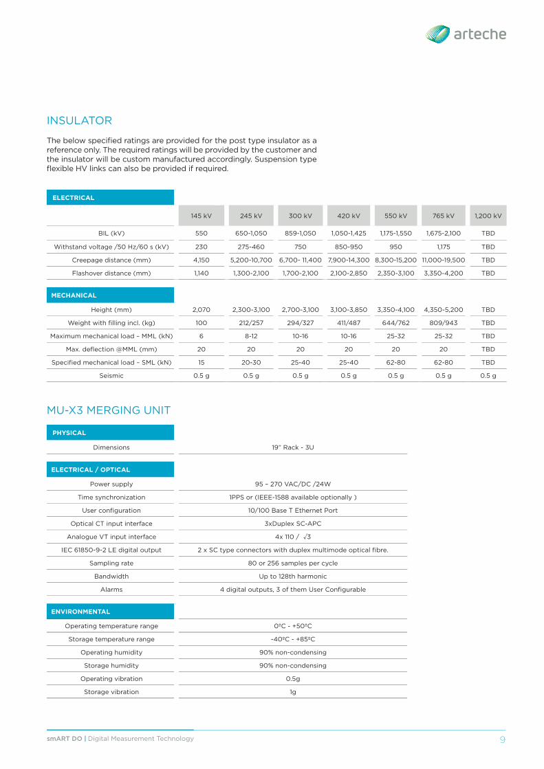
INSULATOR
The below specifi ed ratings are provided for the post type insulator as a reference only. The required ratings will be provided by the customer and the insulator will be custom manufactured accordingly. Suspension type fl exible HV links can also be provided if required.
ELECTRICAL
145 kV 245 kV 300 kV 420 kV 550 kV 765 kV 1,200 kV
BIL (kV) 550 650-1,050 859-1,050 1,050-1,425 1,175-1,550 1,675-2,100 TBD
Withstand voltage /50 Hz/60 s (kV) 230 275-460 750 850-950 950 1,175 TBD
Creepage distance (mm) 4,150 5,200-10,700 6,700- 11,400 7,900-14,300 8,300-15,200 11,000-19,500 TBD
Flashover distance (mm) 1,140 1,300-2,100 1,700-2,100 2,100-2,850 2,350-3,100 3,350-4,200 TBD
MECHANICAL
Height (mm) 2,070 2,300-3,100 2,700-3,100 3,100-3,850 3,350-4,100 4,350-5,200 TBD
Weight with fi lling incl. (kg) 100 212/257 294/327 411/487 644/762 809/943 TBD
Maximum mechanical load – MML (kN) 6 8-12 10-16 10-16 25-32 25-32 TBD
Max. defl ection @MML (mm) 20 20 20 20 20 20 TBD
Specifi ed mechanical load – SML (kN) 15 20-30 25-40 25-40 62-80 62-80 TBD
Seismic 0.5 g 0.5 g 0.5 g 0.5 g 0.5 g 0.5 g 0.5 g
MU-X3 MERGING UNIT
PHYSICAL
Dimensions 19” Rack - 3U
ELECTRICAL / OPTICAL
Power supply 95 – 270 VAC/DC /24W
Time synchronization 1PPS or (IEEE-1588 available optionally )
User confi guration 10/100 Base T Ethernet Port
Optical CT input interface 3xDuplex SC-APC
Analogue VT input interface 4x 110 / 3
IEC 61850-9-2 LE digital output 2 x SC type connectors with duplex multimode optical fi bre.
Sampling rate 80 or 256 samples per cycle
Bandwidth Up to 128th harmonic
Alarms 4 digital outputs, 3 of them User Confi gurable
ENVIRONMENTAL
Operating temperature range 0ºC - +50ºC
Storage temperature range -40ºC - +85ºC
Operating humidity 90% non-condensing
Storage humidity 90% non-condensing
Operating vibration 0.5g
Storage vibration 1g

www.arteche.com ©ARTECHE
Updates: ARTECHE_CT_DMT_ENVersion: A0