smart driver for power reduction in next generation bistable electrophoretic display technology...
TRANSCRIPT

Smart Driver for Power Reduction in Next Generation Bistable
Electrophoretic Display Technology
Michael A. BakerAviral ShrivastavaKaram S. Chatha
Arizona State UniversityTempe, Arizona, USA
April 18, 2023

2
Power: A Critical Constraint in ES
• Impact of energy consumption of embedded systems– Most important factor in usability of electronic devices
Device Battery life Charge time
Battery weight/ Device weight
Apple iPOD 2-3 hrs 4 hrs 3.2/4.8 oz
Panasonic DVD-LX9 1.5-2.5 hrs 2 hrs 0.72/2.6 pounds
Nokia N80 20 mins 1-2 hrs 1.6/4.73 oz
Performance/Power requirements of handhelds Increase by 30X in a decade
Battery capacity Increase by 3X in a decade Considering technological
breakthroughs, e.g. fuel cells

3
Displays: Major power consumer
• LCDs consume 30-60% of power in handhelds– Up to 90% is due to backlight
• HP iPAQ– 320 x 240 QVGA LCD consumes 220 mW
Electrophoretic Displays (EPDs)
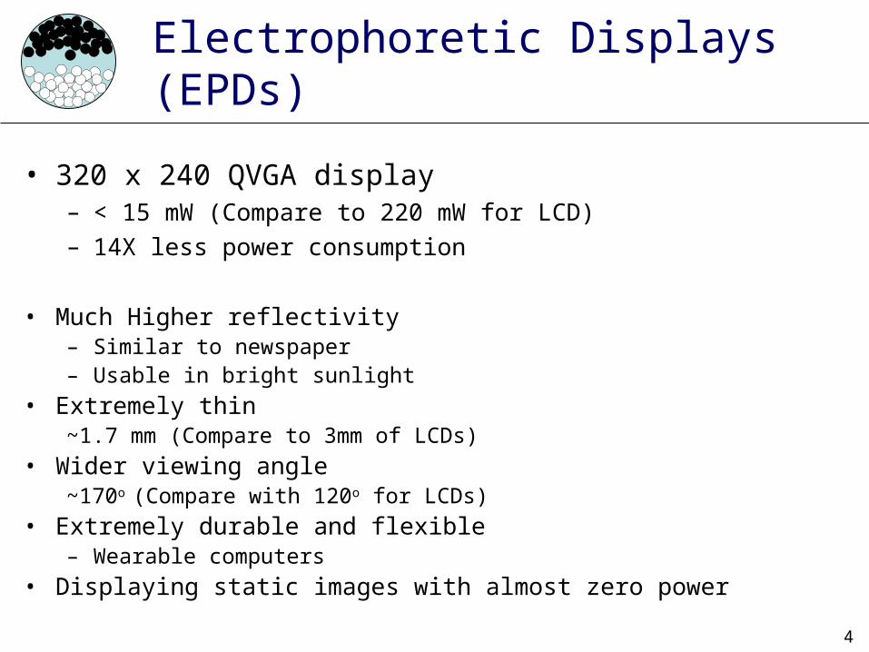
• 320 x 240 QVGA display– < 15 mW (Compare to 220 mW for LCD)– 14X less power consumption
• Much Higher reflectivity– Similar to newspaper– Usable in bright sunlight
• Extremely thin~1.7 mm (Compare to 3mm of LCDs)
• Wider viewing angle~170o (Compare with 120o for LCDs)
• Extremely durable and flexible– Wearable computers
• Displaying static images with almost zero power
4

5
Agenda
• Electrophoretic Displays• Contribution• Previous Work• EPD Power Model• Display Driver
– Naive Driver– Smart/Lazy Driver
• Results• Conclusion
6
EPD: A Bistable Display Technology
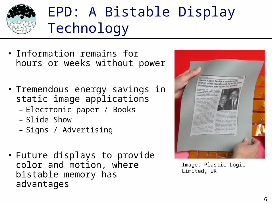
• Information remains for hours or weeks without power
• Tremendous energy savings in static image applications– Electronic paper / Books– Slide Show– Signs / Advertising
• Future displays to provide color and motion, where bistable memory has advantages
Image: Plastic Logic Limited, UK

7
EPD Technology
• Electrically charged particles physically displaced by electric field• Resolution independent of capsule size

8
+-
EPD Technology
Capsule diameter about 50μm
~ 6 capsules/subpixel
~ 17 capsules/pixel
E-Ink Corp.
+-
Negatively charged pigment particle
Positively charged pigment particle
capsule
pixel array (greyscale)

9
Agenda
• Electrophoretic Displays• Contributions• EPD Power Model• Display Driver
– Naive Driver– Smart/Lazy Driver
• Results• Conclusion

10
Contributions
• Power characterization and modeling of EPDs
• Device drivers to use them in video applications– Exploit EPD properties to further optimize
performance and save power?

11
Agenda
• Electrophoretic Displays• Contributions• Related Work• EPD Power Model• Display Driver
– Naive Driver– Smart/Lazy Driver
• Results• Conclusion

12
Previous Work
• EPD technology studied for over 30 years– Fundamental Properties
• [1] EPD Characterization of colloidal suspension (Phillips Laboratories, 1977 )• [2] Model for driving EPDs (Xerox Research Center of Canada, 1979)• [3] EPD ink and capsule characterization (MIT Media Laboratory, 1998)
– Simulation• [4] EPD properties and simulation (Ghent University, 2005)
• Applicable LCD driver power reduction efforts– [5] Reducing driver cost in active matrix displays (Texas Instruments,
1982)
[1] A. L. Dalisa, “Electrophoretic Display Technology”, IEEE Transactions on Electron Devices, Vol. ED-24, No. 7, July 1977 [2] M. A. Hopper, V. Novotny, “An Electrophoretic Display, Its Properties, Model, and Addressing”, IEEE Transactions on Electron Devices, Vol. ED-26, No.
8, August 1979 (Model for driving EPDs)
[3] B. Comiskey, J. D. Albert, H. Yoshizawa, J. Jacobson, “An electrophoretic ink for all-printed reflective electronic displays”, Nature 394, 253-255, 16 July 1998
[4] T. Bert, H. De Smet, F. Beunis, K. Neyts, Complete electrical and optical simulation of electronic paper, Science Direct, 13 October 2005[5] W. Marks, “Power Reduction in Liquid-Crystal Display Modules”, IEEE Transactions on Electron Devices, Vol. ED-29, No. 12, December 1982

13
Agenda
• Electrophoretic Displays• Contributions• Related Work• EPD Power Model• Display Driver
– Naive Driver– Smart/Lazy Driver
• Results• Conclusion
14
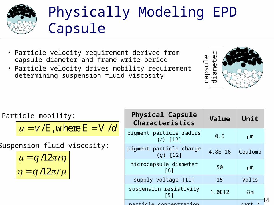
Physically Modeling EPD Capsule
• Particle velocity requirement derived from capsule diameter and frame write period
• Particle velocity drives mobility requirement determining suspension fluid viscosity
Physical CapsuleCharacteristics
Value Unit
pigment particle radius (r) [12] 0.5 m
pigment particle charge (q) [12]
4.8E-16 Coulomb
microcapsule diameter [6] 50 m
supply voltage [11] 15 Volts
suspension resistivity [5] 1.0E12 m
particle concentration [11] 2E16 part./m3
microcapsules/subpixel [6] 6 capsules
/ E, where E V /v d
/12
/12
q r
q r
Particle mobility:
Suspension fluid viscosity:
caps
ule
diam
eter

15
EPD Capsule Power Model
• Particle motion analogous to current in a resistor• Storage capacitor
– Large capacitor per RGB sub-pixel (8.6 pF)– Capsule capacitance is small (<1 pF)– Charge capacitor during row scan then discharged after frame period – Required due to relatively slow electrophoretic response
16
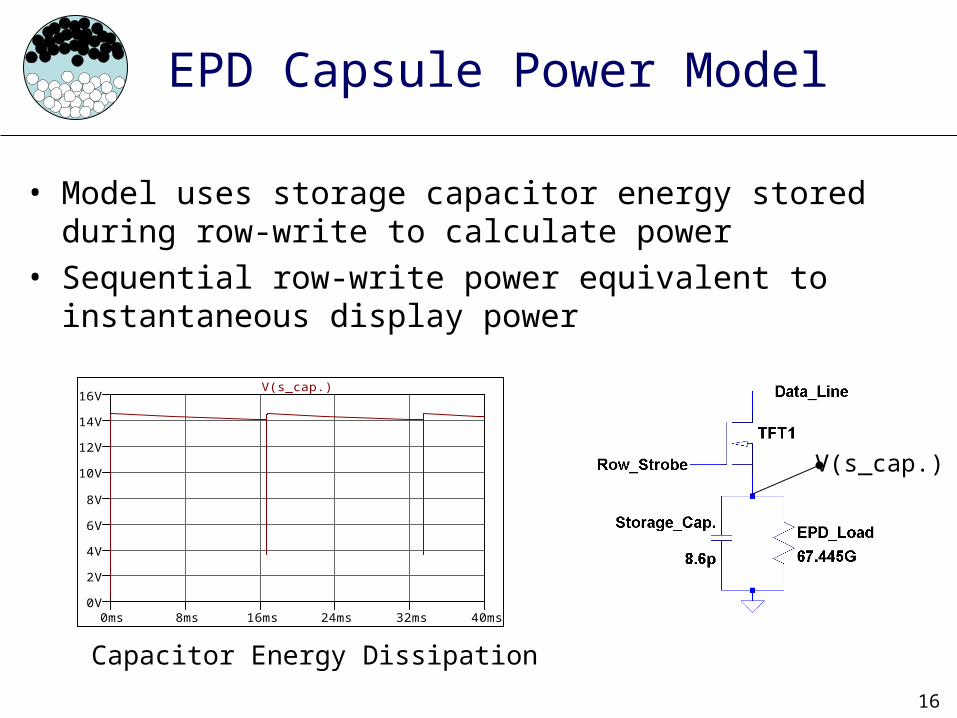
EPD Capsule Power Model
• Model uses storage capacitor energy stored during row-write to calculate power
• Sequential row-write power equivalent to instantaneous display power
0ms 8ms 16ms 24ms 32ms 40ms0V
2V
4V
6V
8V
10V
12V
14V
16VV(s_cap.)
Capacitor Energy Dissipation
V(s_cap.)

17
Agenda
• Electrophoretic Displays• Contributions• Previous Work• EPD Power Model• Display Driver
– Naive Driver– Smart/Lazy Driver
• Results• Conclusion

18
Smart Bistable Display Driver
How can we exploit EPD properties to increase power performance?

19
Smart Bistable Display Driver
• Naive Driver– 100% of image redrawn during refresh or update– Even if portions of the image remain unchanged
in the new image– Wastes energy since display retains unchanged
portions anyway

20
Smart Bistable Display Driver
• Smart Driver– Unchanged pixels not addressed when new image is
drawn--no image degradation– If the 8 bit data value of any subpixel changes, the pixel is
updated
RGB sub-pixels
1 pixel:
Pixel data values: R:11111111 B:11111111 G:11111111 (R:255) (B:255) (G:255)

21
Smart Bistable Display Driver
• Lazy Drivers (Modified Smart Driver)– Similar pixels not addressed when new image is drawn--image
degradation– Some number (1-6 / 8) of LSB from Pixel component values ignored
during decision comparison
• Max pixel color impact due to ignoring bits during comparison:
0 1 2 3 4 5 6 7Bits ignored:
25511111111
25411111110
25211111100
24811111000
24011110000
22411100000
19211000000
12810000000
8 bit value(x3 subpixels): Binary Value:

22
Lazy Driver Example
• Lazy driver configured to ignore specific number of LSBs.• Example: Lazy Driver ignoring 5 bits:
R G B
01100011 11101110 00100011Current value:
01101100 11111010 00110100Next value:
011 111 001
011 111 001
No change, pixel is not updated
01100011 11101110 00100011
01111010 11001100 00111111
011 111 001
011 110 001
Change, pixel is updated

23
Agenda
• Electrophoretic Displays• Contributions• Previous Work• EPD Power Model• Display Driver
– Naive Driver– Smart/Lazy Driver
• Results• Conclusion

24
Driver Simulation
• Simulator takes series of bitmaps extracted from video stream as input
• Outputs series of bitmaps altered in accordance with each driver scheme
• Power is calculated based on the number of pixels written in each row
• Capacitor energy stored in the drive capacitors energy expended per row write

25
Video 1: Display Power

26
Video 1: Display Power

27
Bar
ones
s fr
ame
29E
leca
rd L
td.
Video 1: Image Degradation
no degradation 4 bits
5 bits 6 bits

28
Video 1: Image DegradationB
aron
ess
fram
e 29
4 bits
5 bits 6 bits
Original 5 bits 6 bits

29
Energy Savings vs. QOS

30
QOS and Power Savings Results

31
Ongoing work in EPD
• Generating Greyscale– Complex driving waveforms
used to generate grayscale– Area Ratio Grayscale also
used to achieve gray levels
• Producing Color EPDs– Different color pigment
particles– Frontplane filters
• Improving Response time– Particle mobility
E-Ink Color EPD Prototype
9 gray level ARG element
Sony E-Book with E-Ink 4 bit waveform driven grayscale

32
Conclusion
• Bistability of electrophoretic displays enables power savings via smart drivers
• Smart driver might take advantage of context or user preferences to expand power reduction in exchange for picture quality
E-Ink Bendable Clock
33
Questions?
+-

34
References
1. W. Cheng, Y. Hou, M. Pedram, Power Minimization in a Backlit TFT-LCD Display by Concurrent Brightness and Contrast Scaling, Design, Automation and Test in Europe Conference and Exhibition, Vol.: 1, pp. 252 - 257, 2004
2. I. Choi, H. Shim, N. Chang, Low-Power Color TFT LCD Display for Hand-Held Embedded Systems, International Symposium on Low Power Electronics and Design, August 12-14, 2002
3. NEC NL2432HC17-01B QVGA LCD for mobile applications with touch panel specification4. F. Gatti, A. Acquaviva, L. Benini, B. Ricco’, Low Power Control Techniques For TFT LCD Displays, CASES, October 20025. A. L. Dalisa, Electrophoretic Display Technology, IEEE Transactions on Electron Devices, Vol. ED-24, No. 7, July 19776. S. Inoue, H. Kawai, S. Kanbe, T. Saeki, T. Shimoda, High-Resolution Microencapsulated Electrophoretic Display (EPD) Driven by
Poly-Si TFTs With Four-Level Grayscale, IEEE Transactions on Electron Devices, Vol. 49, No. 8, August 20027. LTSpice manual8. L. Blackwell, LCD Specs: Not So Swift, PC World, Friday, July 22, 2005 9. Ghent University Liquid Crystals & Photonics Group, http://www.elis.ugent.be/elisgroups/lcd/research/elektink.php 10. B. Comiskey, J. D. Albert, H. Yoshizawa, J. Jacobson, An electrophoretic ink for all-printed reflective electronic displays, Nature
394, 253-255 (16 July 1998)11. S. Vermael, K. Neyts, G. Stojmenovik, F. Beunis, L. Schlangen, A 1-Dimensional Simulation Tool for Electophoretic Displays,
Fourth FTW PhD Symposium, Ghent University, 200312. T. Bert, H. De Smet, F. Beunis, K. Neyts, Complete electrical and optical simulation of electronic paper, Science Direct, 13 October
200513. M. A. Hopper, V. Novotny, An Electrophoretic Display, Its Properties, Model, and Addressing, IEEE Transactions on Electron
Devices, Vol. ED-26, No. 8, August 197914. H. Takao, M. Miyasaka, H. Kawai, H. Hara, A. Miyazaki, T. Kodaira, S. W. B. Tam, S. Inoue, T. Shimoda, Flexible Semiconductor
Devices: Fingerprint Sensor and Electrophoretic Display on Plastic, ESSDERC Proceeding of the 34th European, pp. 309-312, September 2004
15. B. W. Marks, Power Consumption in Multiplexed Liquid-Crystal Displays, IEEE Transactions on Electron Devices, Vol. ED-29, No. 8, August 1982
16. B. W. Marks, Power Reduction in Liquid-Crystal Display Modules, IEEE Transactions on Electron Devices, Vol. ED-29, No. 12, December 1982
17. Elecard Ltd., http://www.elecard.com/download/clips.php, videos used with permission18. Semiconductor Gobal LCD Driver IC S6B0723A Specification19. F. Strubbe, (K. Neyts), Determination of the valency of pigment particles in electrophoretic ink, Ghent Univ., November 2005