smart grid and nfpa electrical safety codes and standards
TRANSCRIPT
SpringerBriefs in Fire
Series Editor:James A. Milke
For further volumes:http://www.springer.com/series/10476

Lonny Simonian • Thomas KormanFrederick W. Mowrer • David Phillips
Smart Grid and NFPA Electrical Safety Codes and Standards
Lonny SimonianCalifornia Polytechnic State UniversitySan Luis Obispo, CA, USA
Frederick W. MowrerCalifornia Polytechnic State UniversitySan Luis Obispo, CA, USA
Thomas KormanCalifornia Polytechnic State UniversitySan Luis Obispo, CA, USA
David PhillipsCalifornia Polytechnic State UniversitySan Luis Obispo, CA, USA
ISSN 2193-6595 ISSN 2193-6609 (electronic)ISBN 978-1-4614-3947-9 ISBN 978-1-4614-3948-6 (eBook)DOI 10.1007/978-1-4614-3948-6Springer New York Heidelberg Dordrecht London
Library of Congress Control Number: 2012936828
© Fire Protection Research Foundation 2011National Electrical Code®, NEC® and NFPA 70® are registered trademarks of the National Fire Protection Association, Quincy, MA 02169.This work is subject to copyright. All rights are reserved by the Publisher, whether the whole or part of the material is concerned, speci fi cally the rights of translation, reprinting, reuse of illustrations, recitation, broadcasting, reproduction on micro fi lms or in any other physical way, and transmission or information storage and retrieval, electronic adaptation, computer software, or by similar or dissimilar methodology now known or hereafter developed. Exempted from this legal reservation are brief excerpts in connection with reviews or scholarly analysis or material supplied speci fi cally for the purpose of being entered and executed on a computer system, for exclusive use by the purchaser of the work. Duplication of this publication or parts thereof is permitted only under the provisions of the Copyright Law of the Publisher’s location, in its current version, and permission for use must always be obtained from Springer. Permissions for use may be obtained through RightsLink at the Copyright Clearance Center. Violations are liable to prosecution under the respective Copyright Law.The use of general descriptive names, registered names, trademarks, service marks, etc. in this publication does not imply, even in the absence of a speci fi c statement, that such names are exempt from the relevant protective laws and regulations and therefore free for general use.While the advice and information in this book are believed to be true and accurate at the date of publication, neither the authors nor the editors nor the publisher can accept any legal responsibility for any errors or omissions that may be made. The publisher makes no warranty, express or implied, with respect to the material contained herein.
Reprinted in 2012 by Springer
Printed on acid-free paper
Springer is part of Springer Science+Business Media (www.springer.com)

v
Under the Energy Independence and Security Act (EISA) of 2007, the National Institute of Standards and Technology (NIST) has “primary responsibility to coor-dinate development of a framework that includes protocols and model standards for information management to achieve interoperability of smart grid devices and systems….” 1 Furthermore, NIST 2 de fi nes the term “Smart Grid” as:
a modernization of the electricity delivery system so it monitors, protects and automatically optimizes the operation of its interconnected elements – from the central and distributed generator through the high-voltage transmission network and the distribution system, to industrial users and building automation systems, to energy storage installations and to end-use consumers and their thermostats, electric vehicles, appliances and other household devices.
In this context, “thermostats, electric vehicles, appliances and other household devices” may be considered “utilization equipment.” The NIST Smart Grid Collaboration Site 3 lists a wide range of energy management applications and electrical service provider interactions, including:
On-site generation • Demand response • Electrical storage • Peak demand management • Forward power usage estimation • Load-shedding capability estimation • End load monitoring (submetering) • Power quality of service monitoring • Utilization of historical energy consumption data • Responsive energy control •
Preface
1 Report to NIST on the Smart Grid Interoperability Standards Roadmap, Electric Power Research Institute (EPRI), August 10, 2009 2 ibid 3 http://collaborate.nist.gov/twiki-sggrid/bin/view/SmartGrid/PAP17FacilitySmartGridInformation Standard accessed November 14th, 2010

vi Preface
A Smart Grid Conceptual Model may be portrayed as a set of diagrams and descriptions that are the basis of discussion of the characteristics, uses, behavior, interfaces, requirements, and standards of the Smart Grid. 4 This conceptual model, shown in Fig. 1 , provides a context for analysis of interoperation and standards for the development of the Smart Grid architecture.
Table 1 lists the actors and domains that are referenced in Fig. 1 . This project focuses on the end user, or customer, in the built environment as
shown in Fig. 2 . The implementation of the Smart Grid changes the nature of the electrical distri-
bution system in ways that have a number of different safety implications, including personnel safety, electrical safety, and fi re safety. Because of these safety implications, it is important that relevant safety codes and standards, such as the National Electrical Code, stay abreast of Smart Grid developments.
Before the Smart Grid, electrical power distribution to customers was largely a one-way process, with customers receiving electrical power generated at a bulk gen-eration plant, which was then transmitted and distributed via the existing grid. Under this scheme, limited instrumentation data could be transmitted from a customer to the service provider and, in some instances, remote control could be executed.
Fig. 1 Smart Grid Conceptual Model (ibid)
4 Report to NIST on the Smart Grid Interoperability Standards Roadmap, Electric Power Research Institute (EPRI), August 10, 2009

viiPreface
Under the Smart Grid, electrical power generation and distribution become a two-way process between the customer and the grid. To work effectively and safely, the processes of power generation and distribution, as well as those of instrumenta-tion and control, must be closely coordinated and managed.
Fig. 2 Smart Grid customer domain (ibid)
Table 1 List of Smart Grid actors and domains a
Domain b Actors c
Markets The operators and participants in electricity markets Operations The managers of the movement of electricity Service providers The organizations providing services to electrical customers and utilities Bulk generation The generators of electricity in bulk quantities; may also store energy for later
distribution Transmission The carriers of bulk electricity over long distances; may also store and
generate electricity Distribution The distributors of electricity to and from customers; may also store and
generate electricity Customers The end users of electricity; may also generate, store, and manage the use
of energy; traditionally, three types of customers are identi fi ed, each with their own domain: residential (home), commercial (building/commercial), and industrial. In addition, the end user may be an institutional customer (such as schools and hospitals)
a ibid b Group of actors that have a similar objective c Devices, computer systems or software programs, and/or the organizations that own them

ix
Kathleen H. Almand Executive Director , Fire Protection Research Foundation
David Clements CEO and Executive Director , International Association of Electrical Inspectors
Mark Earley Chief Electrical Engineer , National Fire Protection Association
Bill Galloway Assistant SFM , SC Of fi ce of the State Fire Marshal
Michael Johnston Executive Director of Standards and Safety , National Electrical Contractors Association
Shawn Paulsen Manager of Conformity Assessment, Regulator , CSA International
Dean Prochaska National Coordinator for Smart Grid , National Institute of Standards and Technology
Al Scolnik Vice President , National Electrical Manufacturers Association
John Thompson Director, Principal Engineers (PDE) , Underwriters Laboratories Inc.
Project Committee Members

xi
Portions of this report are reproduced with permission from the National Electrical Code,® NFPA 70® 2011, NFPA 110, Emergency and Standby Power Systems , and NFPA 111, Stored Electrical Energy Emergency and Standby Power Systems , all of which are copyright of 2010 National Fire Protection Association. This material is not the complete and of fi cial position of the NFPA on the reference subject, which is represented solely by the standard in its entirety.
This work was made possible by the Fire Protection Research Foundation (an af fi liate of the National Fire Protection Association). The authors are indebted to the project-steering committee members, smart grid task group members, and industry representatives for their valuable suggestions.
Acknowledgments

xiii
AMI Advanced Metering Infrastructure AMR Automated Meter Reading BIPV Building-Integrated Photovoltaics CHP Combined Heat and Power CES Community Energy Storage EISA Energy Independence and Security Act EIS Energy Information Systems EMS Energy Management System EMGS Energy Microgeneration Systems EMCS Energy Monitoring and Control FM Global Factory Mutual HAN Home Area Network IEEE Institute of Electrical and Electronic Engineers NEC National Electrical Code NEMA National Electrical Manufacturers Association NIST National Institute of Standards and Technology RF Radio Frequency MicroCHP Micro Combined Heat and Power MFC Microbial Fuel Cell PV Photovoltaics BIPV Building-Integrated Photovoltaics PEV Plug-in Electric Vehicles PHEV Plug-in Hybrid Electric Vehicles TES Thermal Energy Storage TOU Time of Use UL Underwriters Laboratories, Inc UPS Uninterruptible Power Supplies
Glossary of Acronyms


xv
1 Task 1: Technology Review and Safety Assessment ................................. 11.1 Scope and Approach ............................................................................ 11.2 Smart Grid Technologies Within the Customer Domain ..................... 1
1.2.1 Smart Meters ............................................................................ 21.2.2 Energy Microgeneration, Co-generation,
and Generation Systems ........................................................... 71.2.3 Energy Storage Systems ........................................................... 111.2.4 Plug-In Vehicles ....................................................................... 131.2.5 Community Energy Storage ..................................................... 141.2.6 Summary .................................................................................. 16
1.3 Review of NFPA 70, National Electric Code ....................................... 171.4 Template for Assessment of Potential Smart Grid
Technology Failures ............................................................................. 18
2 Task 2: Regulatory Review and Gap Assessment .................................... 21
2.1 Methodology ........................................................................................ 21 2.1.1 Background .............................................................................. 21 2.1.2 Scope and Approach ................................................................ 22
2.2 Review of NFPA Standards .................................................................. 22 2.2.1 NFPA 70 ................................................................................... 22 2.2.2 NFPA 70E ................................................................................ 34 2.2.3 NFPA 110 ................................................................................. 36 2.2.4 NFPA 111 ................................................................................. 37
2.3 Identi fi cation of Other Standards ......................................................... 39 2.3.1 National Electrical Manufacturers Association (NEMA) ........ 39 2.3.2 Underwriters Laboratories, Inc (UL) ....................................... 40 2.3.3 National Institute of Standards and Technology
(NIST) Priority Action Plans (PAPS) ...................................... 41 2.3.4 Institute of Electrical and Electronic Engineers (IEEE) .......... 41
2.4 Assessment of Gaps/Inconsistencies .................................................... 42 2.5 Summary Matrix .................................................................................. 60
Contents

xvi Contents
3 Task 3: Workshop Presentation ................................................................. 61
4 Task 4: Roadmaps ....................................................................................... 634.1 Scope and Approach ............................................................................ 634.2 Safety Standards Roadmap .................................................................. 63
4.2.1 Implementation Stages ............................................................. 634.2.2 NFPA Code Provisions Impacted ............................................. 654.2.3 Needed Changes or New Provisions to the NEC ..................... 654.2.4 Implementation Timeline ......................................................... 65
4.3 Information Gaps Roadmap ................................................................. 704.3.1 Implementation Stages ............................................................. 70
4.3.2 Research Project Statements .................................................... 70
Appendices ......................................................................................................... 73Appendix A: Task 1 Comment Resolution Form ................................................ 74Appendix B: Task 2 Comment Resolution Form ................................................ 85
xvii
Fig. 1 Smart Grid Conceptual Model (ibid) .................................................. vi Fig. 2 Smart Grid customer domain (ibid) .................................................... vii
Fig. 1.1 Technology review and safety assessment work sequence ................. 2 Fig. 1.2 Smart mesh con fi guration in a commercial building .......................... 3 Fig. 1.3 Smart plug strip con fi guration ............................................................ 4 Fig. 1.4 Community Energy Storage System .................................................. 15
Fig. 4.1 NFPA codes and standards making process (ibid) ............................. 69
List of Figures

xix
Table 1 List of Smart Grid actors and domains ............................................ vii
Table 1.1 Summary of Smart Grid Technologies ............................................ 16 Table 1.2 Smart grid template for failure mode effect analysis....................... 20
Table 2.1 Assessment of gaps/inconsistencies ................................................ 43 Table 2.2 Summary matrix .............................................................................. 58
Table 4.1 Smart grid topic prioritization ......................................................... 64 Table 4.2 Smart grid customer prioritization ................................................... 64 Table 4.3 NFPA code impact ........................................................................... 66 Table 4.4 Proposed NEC changes ................................................................... 67 Table 4.5 Information gaps .............................................................................. 70
List of Tables


1L. Simonian et al., Smart Grid and NFPA Electrical Safety Codes and Standards, SpringerBriefs in Fire, DOI 10.1007/978-1-4614-3948-6_1, © Fire Protection Research Foundation 2011
1.1 Scope and Approach
A review of Smart Grid technologies was conducted with focus on the Customer domain. This included: the impact that Smart Grid technologies have within Customers’ internal environments, the effect that Smart Grid technologies have from Service Provider or Operations domains upon Customers, and the effect that Customers have upon Distribution or Market domains. The approach is shown in Fig. 1.1 .
1.2 Smart Grid Technologies Within the Customer Domain
Current and emerging Smart Grid technologies were reviewed and the implications that these technologies may have upon the built environment (such as a facility’s safety features) were assessed wherever the National Electrical Code (NEC) has jurisdiction. This included all power distribution and control systems throughout a facility. Speci fi c areas of focus include the electrical service or utility point of connection interface (smart meter), energy generation and microgeneration systems (such as photovoltaic cells, wind power, micro hydro, emergency and standby generators, and fuel cells), energy conversion/storage systems (such as batteries, Uninterruptible Power Supplies (UPS), and thermal energy storage), plug-in vehicles, and community energy storage.
Customers who adopt smart grid technology gain control over the amount and time of day of electricity consumption of loads. For residential customers, the smart meter will generally be installed by the utility or service provider, and the customer may acquire additional devices/systems to take advantage of the information and communication provided by the meter. For example, if these customers switch to a time of use pricing system, they can bene fi t by shifting non time-speci fi c loads to cheaper times, optimizing micro-generation systems for maximum output at high
Chapter 1 Task 1: Technology Review and Safety Assessment

2 1 Task 1: Technology Review and Safety Assessment
price times, and using on-site storage to supply the grid or the home at high price times. The commercial customer may acquire additional devices/systems to take advantage of the information and communication provided by the meter. Many commercial customers have already taken advantage of a time of use pricing system, in which they perform non-critical operations at times when that rate structure favors a lower rate. For example, a commercial customer may produce ice during the night to use during the day for a chilled water system.
1.2.1 Smart Meters
A smart meter is an advanced electric meter that records consumption in intervals of 1 h or less and communicates that information at least daily via some communica-tions network back to the utility for monitoring and billing purposes (telemetering). Smart meters enable two-way communication between the customer’s meter and the electrical utility serving the customer. Smart meters differ from a home energy monitor in that they can gather data for remote reporting. Smart meters usually involve a different technology mix, such as real-time or near real-time sensors, power outage noti fi cation, and power quality monitoring. These additional features differentiate smart meters from Automated Meter Reading (AMR). They are similar in many respects to Advanced Metering Infrastructure (AMI) meters. Smart meters are a less costly alternative to traditional interval or time-of-use meters and are intended to be used on a wide scale with all customer classes, including residential, commercial, and industrial. It should be noted that smart meters may be part of a smart grid, but alone do not constitute a smart grid.
Most smart meter systems currently in development use programmable solid-state meters using secure wireless network technology. Each smart meter is equipped
Fig. 1.1 Technology review and safety assessment work sequence

31.2 Smart Grid Technologies Within the Customer Domain
with a network radio, which transmits meter data to an electric network access point. The system uses Radio Frequency (RF) mesh technology, which allows meters and other sensing devices to securely route data via nearby meters and relay devices, creating a “mesh” of network coverage. An example of a Smart Mesh Con fi guration in a Commercial Building is shown in Fig. 1.2 .
The system supports two-way communication between a customer’s meter and the electric utility. Some smart meters have remotely upgradeable systems, such as fi rmware, providing the ability to implement future innovations easily and securely.
A smart meter electric network access point collects meter data from nearby electric meters and periodically transfers this data to the electric utility via a secure cellular network. Each RF mesh-enabled device (meters, relays) is connected to several other mesh-enabled devices, which function as signal repeaters, relaying the data to an access point. The access point device aggregates, encrypts, and sends the data back to the electric utility over a secure commercial third-party network. The resulting RF mesh network can span large distances and reliably transmit data over rough or dif fi cult terrain. If a meter or other transmitter drops out of the network, its neighbors fi nd another route. The mesh continually optimizes routing to ensure information is passed from its source to its destination as quickly and ef fi ciently as possible.
Fig. 1.2 Smart mesh con fi guration in a commercial building
4 1 Task 1: Technology Review and Safety Assessment
1.2.1.1 Energy Management Systems
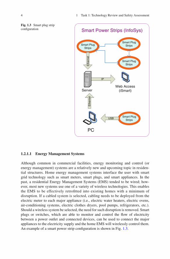
Although common in commercial facilities, energy monitoring and control (or energy management) systems are a relatively new and upcoming topic in residen-tial structures. Home energy management systems interface the user with smart grid technology such as smart meters, smart plugs, and smart appliances. In the past, a residential Energy Management Systems (EMS) tended to be wired; how-ever, most new systems use one of a variety of wireless technologies. This enables the EMS to be effectively retro fi tted into existing homes with a minimum of disruption. If a cabled system is selected, cabling needs to be deployed from the electric meter to each major appliance (i.e., electric water heaters, electric ovens, air-conditioning systems, electric clothes dryers, pool pumps, refrigerators, etc.). Should a wireless system be selected, the need for such disruption is removed. Smart plugs or switches, which are able to monitor and control the fl ow of electricity between a power outlet and connected devices, can be used to connect the major appliances to the electricity supply and the home EMS will wirelessly control them. An example of a smart power strip con fi guration is shown in Fig. 1.3 .
Smart Power Strips (InfoSys)
Eth
erne
t
Smart PlugStrips
Smart PlugStrips
Smart PlugStrips
Smart PlugStrips
Eth
erne
t
USB
Web Access(iSmart)
IP
Server
PC
Fig. 1.3 Smart plug strip con fi guration

51.2 Smart Grid Technologies Within the Customer Domain
Energy Information Systems (EIS) and Energy Monitoring and Control Systems (EMCS) have been in use in commercial applications for several years. A commer-cial customer may obtain a more favorable rate structure for allowing reductions in energy usage, and responding to utility requests for reduced energy consumption, by activating reduced energy modes in commercial buildings.
1.2.1.2 Time of Use Metering/Rate Structures
Time of Use (TOU) net metering employs a specialized reversible smart (electric) meter that is programmed to determine net electricity usage (or contribution) any time during the day. Time-of-use allows utility rates and charges to be assessed based on when the electricity was used (i.e., day/night and seasonal rates). Typically the production cost of electricity is highest during the daytime peak usage period and low during the night, when demand on the utility system is lower. Time of use metering can play a signi fi cant role when there is a customer-generated energy source, since, for example, solar power systems tend to produce energy during the daytime peak-price period, and produce little or no power during the night period, when the cost per kilowatt is low. Because a smart meter records and communicates customer consumption back to the utility for monitoring time of use metering, rate structures may increase consumers’ use of EMS.
1.2.1.3 Load Shedding/Demand Response
Load shedding is an intentional, utility-initiated loss of electrical power to a speci fi c customer or group of customers. Electric utility companies have historically used load shedding as a last-resort measure in order to avoid a total blackout of the power system. The implementation of load shedding is usually in response to a situation where the demand for electricity exceeds the power supply capability of the net-work. The implementation of load shedding generally results from one of two cases: insuf fi cient generation capacity or inadequate transmission infrastructure to deliver suf fi cient power to the area where it is needed. In a Stage 1 emergency, only a general call for voluntary conservation is issued, while Stage 2 emergency results in power being temporarily cut off to certain large users, who have agreed to this arrangement in exchange for lower rates. When a Stage 3 power emergency is declared, electricity to select customers is shut off for a fi xed period of time, which can range from 60 min to 2½ h.
Through the use of smart meters, load shedding also may be implemented by the electric utility to selectively “shed” designated loads (i.e., electric water heaters, electric ovens, air-conditioning systems, electric clothes dryer, pool pumps, refrig-erators, etc.), rather than customers, during periods of high demand. A HAN or EMS (via a smart meter) could reduce load and turn off appliances; or the utility could bypass these systems and directly shut-down major appliances (such as A/C and water heaters). The EMS can be a module in the smart meter or a stand-alone device in the home or business.
6 1 Task 1: Technology Review and Safety Assessment
Demand response appliances could reduce an electrical utility’s base load during peak usage hours via a request from either the customer or utility provider. Several Manufacturers are currently developing residential smart appliances (240 V loads such as air-conditioning units, electrical ovens, electric clothes dryers, etc.) that are able to communicate with, and can be monitored and controlled by, a smart meter.
From a customer’s perspective the smart meter will be able to provide:
Improved home energy management through Home Area Network (HAN) • technologies that will give customers more control over the energy usage of appliances, equipment, lighting, etc. HAN technology in the home can enable the electric utility to better match • energy supply with demand (if the HAN communicates with a Smart Meter), to reduce the possibility of brownouts Smart charging for electric vehicles, taking advantage of off-peak rates • Integration of customers’ on-site energy generation to eliminate the need for • expensive transmission of energy from a remote source, and reduce customers’ vulnerability to outages Smart charging for electric thermal storage systems (i.e., in-ground heating • systems, unit heaters)
The potential impact that smart meter technologies (including Energy Management Systems, Time of Use Metering/Rate Structures, and Load Shedding/Demand Response) have upon safety principals embedded in the NEC was assessed. These safety principles included personnel safety (e.g. shock/electrocution hazards), electrical safety (e.g., potential to damage other electrical/electronic equipment), and fi re safety (e.g., potential to start a fi re). Emphasis was placed upon where those technologies would affect distribution system over-current protection (such as breakers and fuses), and upon other electrical safety devices (such as AFCIs), which have been shown to be susceptible to smart meter wireless transmission. The following areas were identi fi ed:
Dramatic increase in data communication, including: dedicated low voltage • wired systems, low voltage wired systems impressed upon line voltage carriers, and wireless systems between smart grid appliances/plugs and smart meters, or between devices and home energy management and control systems Critical circuits for life-safety systems—including special needs equipment such • as patient care equipment (ventilators, diagnosis equipment, etc.)—will need to remain powered during load shedding Power or control wiring installed by licensed electrical contractors may be • required to tie into panelboards/load centers Grounding and bonding for all components will need to be provided • Sensors will be needed to connect major electrical loads to a smart meter • Susceptibility of smart systems to frequent inrush currents from switching large • appliance loads Limitation should be established on the amount of harmonics induced from Class • 2 wiring

71.2 Smart Grid Technologies Within the Customer Domain
Equipment to be certi fi ed/listed • Quali fi cation of installers • Inspection of installations by quali fi ed persons •
1.2.2 Energy Microgeneration, Co-generation, and Generation Systems
Energy Microgeneration Systems (EMGS) refer to the small-scale generation of heat and/or power by individual customers, small businesses, and communities to meet their own needs and as alternatives to traditional centralized grid-connected power. Microgeneration of energy includes the generation of energy from solar, wind, fuel cell, and other sources by consumers, not by an electric utility. Although this may be motivated by practical considerations, such as unreliable grid power or a long distance from the grid, the term is mainly used currently for environmentally-conscious approaches that aspire to zero or low-carbon footprints. Currently, the most common forms of microgeneration technologies include:
Photovoltaic • Small scale wind turbine • Micro hydro • Fuel cell • Plant microbial fuel cell • Micro Combined Heat and Power (MicroCHP) •
Emergency generators, including diesel fueled and to a lesser degree propane and natural gas fueled, are commonly installed whenever emergency power is required for a facility. Electrical co-generation refers to on-site generation equip-ment that may be used during peak hours to supply either a customer’s facility load or the electric grid.
1.2.2.1 Photovoltaics
Photovoltaics (PV) is a method of generating electrical power by converting solar radiation into direct current electricity using semiconductors that exhibit a photo-voltaic effect. Photovoltaic power generation employs solar panels comprising a number of cells containing a photovoltaic material. Photovoltaic arrays are often associated with buildings: either integrated into them, mounted on them, or mounted nearby on the ground. Arrays are most often retro fi tted into existing buildings, usually mounted on top of the existing roof structure or on existing walls. Alternatively, an array can be located separate from a building but connected via cabling to supply power to the building.
Building-integrated Photovoltaics (BIPV) are increasingly incorporated into new domestic and industrial buildings as a principal or ancillary source of electrical power.

8 1 Task 1: Technology Review and Safety Assessment
Typically, an array is incorporated into the roof or walls of a building. Roof tiles with integrated PV cells are also becoming more common.
1.2.2.2 Small Scale Wind Turbines
Wind turbines provide a means for the conversion of wind energy into electricity. Small-scale wind power is the name given to wind generation systems with the capacity to produce up to 50 kW of electrical power. Buildings that might otherwise rely on diesel generators may use wind turbines to displace diesel fuel consumption. Individuals may purchase these systems to reduce or eliminate their dependence on grid electricity for economic or other reasons, or to reduce their carbon footprint. Wind turbines are becoming more frequently used for household electricity genera-tion in conjunction with battery storage.
Grid-connected wind turbines may use grid energy storage, displacing purchased energy with local production when available. Off-grid system users can either adapt to intermittent power or use batteries, photovoltaic, or diesel systems to supplement the wind turbine. Equipment such as parking meters or wireless internet gateways may be powered by a wind turbine that charges a small battery, replacing the need for a connection to the power grid.
1.2.2.3 Micro Hydro
Micro hydro is a term used for hydroelectric power installations that typically produce up to 100 kW of power. These installations can provide power to an isolated home or small community, or are sometimes connected to electric power networks. There are many of these installations around the world, particularly in developing nations as they can provide an economical source of energy without the purchase of fuel.
Micro hydro systems complement photovoltaic solar energy systems because in many areas, water fl ow, and thus available hydro power, is highest in the winter when solar energy is at a minimum. Micro hydro is frequently accomplished with a pelton wheel for high head, low fl ow water supply. The installation is often just a small dammed pool, at the top of a waterfall, with several hundred feet of pipe leading to small generator housing.
Through the use of power control devices, it is becoming easier to operate generators at an arbitrary frequency and feed the output through an inverter which produces output at grid frequency. Power electronics now also allow the use of permanent magnet alternators that produce variable AC that can be stabilized. This approach allows low speed/low head water turbines to be competitive; they can run at an optimum speed for extraction of energy and the frequency conversion is controlled by power electronics instead of the generator. Very small installations—a few kilowatts or smaller—may generate direct current and charge batteries for peak use times.
91.2 Smart Grid Technologies Within the Customer Domain
1.2.2.4 Fuel Cells
Electrochemical devices called fuel cells were invented about the same time as the battery. Fuel cell development has increased in recent years due to an attempt to increase conversion ef fi ciency of chemical energy stored in hydrocarbon or convert hydrogen fuels into electricity. A fuel cell is an electrochemical cell that converts a source fuel into an electric current. It generates electricity inside a cell through a reaction between a fuel and an oxidant, triggered in the presence of an electrolyte. The reactants fl ow into the cell, and the reaction products fl ow out of it, while the electrolyte remains within it. Fuel cells can operate continuously as long as the necessary reactant and oxidant fl ows are maintained. Many combinations of fuels and oxidants are possible. A hydrogen fuel cell uses hydrogen as its fuel and oxygen (usually from air) as its oxidant. Other fuels include hydrocarbons and alcohols. Other oxidants include chlorine and chlorine dioxide.
1.2.2.5 Plant Microbial Fuel Cells
A Microbial Fuel Cell (MFC) is a device that converts chemical energy to electrical energy by the catalytic reaction of microorganisms. A typical microbial fuel cell consists of anode and cathode compartments separated by a cation (positively charged ion) speci fi c membrane. In the anode compartment, fuel is oxidized by microorganisms, generating electrons and protons. Electrons are transferred to the cathode compartment through an external electric circuit, and the protons are trans-ferred to the cathode compartment through the membrane. Electrons and protons are consumed in the cathode compartment, combining with oxygen to form water. In general, there are two types of microbial fuel cells: mediator and mediator-less microbial fuel cells. Microbial fuel cells have a number of potential uses. The fi rst and most obvious is harvesting the electricity produced for a power source. Virtually any organic material could be used to ‘feed’ a fuel cell. It is conceivable that MFCs could be installed in septic tanks, where bacteria would consume waste material from the water and produce supplementary power for a building. MFCs are a clean and ef fi cient method of energy production. 1
1.2.2.6 Combined Heat and Power (CHP) and Micro CHP (MicroCHP) Installations
Combined Heat and Power (CHP) fuel cells have demonstrated superior ef fi ciency for years in industrial plants, universities, hotels, and hospitals. Residential and small-scale commercial fuel cells are now becoming available to ful fi ll both
1 Allen, R.M. and Bennetto, H.P. 1993. Microbial fuel cells—Electricity production from carbohy-drates. Appl. Biochem. Biotechnology, 39/40, pp. 27–40
10 1 Task 1: Technology Review and Safety Assessment
electricity and heat demand from one system. Fuel cell technology in a compact system is currently available to convert natural gas or propane into both electricity and heat. In the future, new developments in fuel cell technologies will likely allow these power systems to be fueled from biomass instead of fossil fuels, directly converting a home fuel cell into a renewable energy technology.
Micro Combined Heat and Power (MicroCHP) systems such as home fuel cells and co-generation for of fi ce buildings and factories are currently in development. The system generates constant electric power (selling excess power back to the grid when it is not consumed), and produces hot air and water from the waste heat. MicroCHPs are usually less than 5 kWh for a residential or commercial building fuel cell.
Most residential fuel cells fi t either inside a mechanical room or outside a home or business, and can be discreetly sited to fi t within a building’s design. The system operates like a combination furnace, hot water heater and electricity provider—all in one compact unit. Some of the newer home fuel cells can generate anywhere between 1 and 5 kWh (3.6–18 MJ)—optimal for larger homes (of 4,000 sq ft or more), especially if pools, spas, and radiant fl oor heating are planned. Other uses include a back-up source of power for essential loads like refrigerator/freezers and computer electronics. Deploying a system’s heat energy ef fi ciently to a resi-dence or business for hot water applications displaces the electricity or gas otherwise burned to create that heat, further reducing overall energy bills. Retail outlets like fast food chains, coffee bars, and health clubs gain operational savings from hot water heating. 2
Many residential fuel cells are designed to operate 24 h a day, 7 days a week. Connected to the utility grid through a residence’s main service panel and using net metering, residential fuel cells are designed to integrate with existing electrical and hydronic systems. In the event of an interruption of electric power via the grid, the system automatically switches to a grid-independent operational mode to provide continuous backup power for dedicated circuits in a residence while the grid is down. Most designs also allow for off-the-grid operation.
Similar to the discussion in the previous section, the potential impact that Energy Microgeneration and Generation System technologies have upon safety principals embedded in the NEC was assessed. The potential impacts of these technologies include the following:
Requirements for system interconnection • Additional noti fi cation and safety devices required to alert personnel to and • protect them from the presence of two way power Protection for chemical conversion of hydrocarbon fuels into electrical energy • Direct current output from an EMGS to a building • Accommodations for manual disconnect switches •
2 What is microgeneration? Jeremy Harrison, Claverton Energy Group Conference, Bath, Oct 24th 2008
111.2 Smart Grid Technologies Within the Customer Domain
Interconnection of the grounding system • Shutoff and/or dummy-load devices for wind power generation during high • winds, or when power generated exceeds requirements/storage system capacity Manual overrides of automatically controlled circuits • Use of direct current by consumers directly from their EMGS • Conversion of DC generated power into AC as required for many appliances, or • for feeding excess power into a commercial power grid via an inverter or grid-interactive inverter Limiting harmonics that may be introduced into the electric grid by inverters, • especially in residential applications where grid-adjacent houses may use different inverters Wiring Methods • Overcurrent and overload protection • Certi fi ed/listed equipment •
1.2.3 Energy Storage Systems
A major issue associated with the smart grid and increase of energy generation from renewable sources is that energy is often needed when nature is not able to provide the source. Even renewable energy must be stored in order to make it reliable. Wind blows intermittently and so some form of storage is required to compensate for calm periods. Solar energy is equally not available on cloudy days and during the night-time, so stored energy must be available to compensate for the loss of sunlight.
The American Recovery and Reinvestment Act of 2009 helped fi nance research into energy storage and its integration with smart electrical grids. Electricity is transmitted in a closed circuit, and for essentially all practical purposes cannot be stored in large quantities as electrical energy. This means that changes in demand cannot be accommodated without either cutting supply (by brownouts or blackouts) or by storing the electric energy in another medium. Storage methods include, but are not limited to the following: chemical, biological, electrochemical, electrical, mechanical, thermal, and fuel conservation storage. Energy storage can be accom-plished by use of a series of deep cycle, stationary or sealed maintenance-free batteries (the most common solution) or other means of energy storage (e.g. hydrogen fuel cells, fl ywheel energy storage, pumped-storage hydroelectric, compressed air tanks, etc.). The primary methods employed today are described in this section.
1.2.3.1 Batteries
An early solution to the problem of storing energy for electrical purposes was the development of the battery as an electrochemical storage device. Batteries have previously been of limited use in electric power systems due to their relatively small

12 1 Task 1: Technology Review and Safety Assessment
capacity and high cost; however newer battery technologies have been developed that can now provide signi fi cant utility scale load-leveling capabilities. A similar possible solution to deal with the intermittent issue of solar and wind energy may be found in capacitive storage.
1.2.3.2 Uninterruptible Power Supply (UPS) Systems
Although not a conventional energy storage device, uninterruptible power supplies contain storage batteries which provide power to select loads. The on-battery run time of most UPS is relatively short—5 to 15 min being typical for smaller units—but suf fi cient to allow time to bring an auxiliary power source on line, or to properly shut down the connected equipment. Although once previously reserved for very large installations of 10 kW or more, advances in technology have now permitted UPSs to be available as a common consumer device, supplying 500 W or less. In a smart grid environment, a UPS’s storage batteries could lower demand or supply the grid during peak hours or in response to an electricity provider’s request.
1.2.3.3 Thermal Energy Storage
In the 1980s, a number of manufacturers carefully researched Thermal Energy Storage (TES) to meet the growing demand for air conditioning during peak hours. Today, several companies manufacture TES systems. The most popular form of thermal energy storage for cooling is ice storage, since it can store more energy in less space than water storage and it is also less costly than energy recovered via fuel cells or fl ywheels. Thermal storage has cost-effectively shifted gigawatts of power away from daytime peak usage periods. It works by creating ice at night when electricity is usually less costly, and then using the ice to cool the air in buildings during the hotter daytime periods. There are several advantages of thermal storage: commercial electrical rates are lower at night, it takes less energy to make ice when the ambient temperature is cool at night (therefore, source energy from the power plant is saved), and a smaller (more ef fi cient system) can do the job of a much larger unit by running for more hours. 3 Another form of thermal energy storage is Electric Thermal Storage (ETS). In a simple residential ETS system heating units are placed in the rooms where the most heat is required. During off-peak hours electric energy is converted into heat and stored in high-mass units, or bricks, made of dense ceramic material. During peak hours an electric fan circulates the heat from the bricks to heat the home. The temperature is controlled by outside sensors that adjust the amount of power intake to that needed to keep the room(s) at the required comfort temperature.
3 ASHRAE Journal-Reprinted by CALMAC Manufacturing Corporation September 2003
131.2 Smart Grid Technologies Within the Customer Domain
The potential impacts of Energy Storage System technologies on electrical safety principals embedded in the NEC will include:
Battery meter (for charging rate and voltage) installation requirements • Protection of overcharging energy storage systems to prevent failures • Charging and discharging of ESS • Charge controller for charging the batteries or other energy storage • Provisions for converting DC battery power into AC as required for many appli-• ances, or for feeding excess power into a commercial power grid, an inverter or grid-interactive inverter Protection against overcharging of batteries to prevent explosions • Guidelines for the placement of, and clearance requirements for, fuel cells • Load and Demand factors •
1.2.4 Plug-In Vehicles
Plug-in vehicles fall into one of two categories: Plug-in Hybrid Electric Vehicles (PHEV) or Plug-in Electric Vehicles (PEV). Both categories of electric vehicles differ from fossil fuel-powered vehicles in that they are able to consume electricity which could be generated from a wide range of sources, including fossil fuels, nuclear power, and renewable sources such as tidal power, solar power, and wind power or any combination of those. The energy could then be transmitted to the vehicle through use of overhead lines, wireless energy transfer such as inductive charging, or a direct connection through an electrical cable. The electricity may then be stored onboard the vehicle using a battery, fl ywheel, or supercapacitors. Vehicles with combustion engines can usually only derive their energy from a single or a few sources, usually non-renewable fossil fuels. A key advantage of electric or hybrid electric vehicles is regenerative braking and suspension; the ability to recover energy normally lost during braking which can be restored to the onboard battery.
1.2.4.1 Charging EV’s and Charging Stations
Electric vehicles typically charge from conventional power outlets or dedicated charging stations. Depending on the voltage available (120, 208, 240, or 480 V), the process may take only a fraction of an hour to several hours. For residential applications, since the charging voltage is limited to 240V the process will usually take several hours. If a large proportion of private vehicles were to convert to grid electricity it would increase the demand for generation and transmission, and con-sequent emissions; however, overall energy consumption and emissions would diminish because of the higher ef fi ciency of electric vehicles. It is conceivable that the existing power plant and transmission infrastructure is already suf fi cient, assuming that most charging would occur overnight, using the most ef fi cient

14 1 Task 1: Technology Review and Safety Assessment
off-peak base load sources. One concern, however, is that the distribution system, and speci fi cally distribution system transformers, will be undersized to accommo-date the needs of PEV nighttime charging.
1.2.4.2 Vehicle-to-Grid Storage Systems
Grid energy storage (or large-scale energy storage) lets energy producers send excess electricity via the grid to temporary electricity storage sites that become energy producers when electricity demand increases. Grid energy storage is particu-larly important in matching supply and demand over a 24 h period of time. A pro-posed variant of grid energy storage is called Vehicle-to-Grid energy storage, where modern electric vehicles that are plugged into the energy grid can release the stored electrical energy in their batteries back into the grid when needed.
The potential impacts of Plug-in Vehicle technologies on electrical safety principals embedded in the NEC will include:
Battery meter (for charging rate and voltage) installation requirements • Meters for power consumption • Protection of overcharging energy storage systems to prevent failures • Charging and discharging of Vehicle-to-Grid storage systems • Charging and discharging of PHEVs, PEVs, and other on-site energy storage • systems
1.2.5 Community Energy Storage
Community Energy Storage (CES) de fi nes an approach where smaller packages of battery energy storage are available to more than one customer with limited back-up time. For residential application, CES are typically 25 kW with 1–2 h of back-up time, and are deployed in neighborhoods, on street corners, or along backyard utility rights-of-way. For commercial applications, CESs function the same as in a residential environment, but instead of serving a cluster of six to ten residential customers, CES interconnect several commercial facilities. CES for commercial applications that normally are supplied from three phase 277/480 V systems will have the greatest impact amongst facilities situated in a campus environment, such as a business of fi ce park.
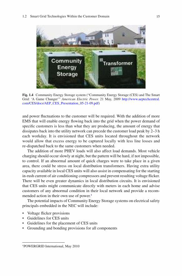
Figure 1.4 depicts a CES adjacent to a standard utility transformer feeding six to ten residential customers. The CES units are connected on the low-voltage side of the utility transformer and store 120/240-V power for individual customers. The intent would be to place a utility-controlled device at the edge of the grid to provide voltage control and improve service reliability. As more sophisticated electronic loads, such as computers, appliances, etc. (which require greater service reliability) are added—along with additional PHEV charging units—greater control of voltage
151.2 Smart Grid Technologies Within the Customer Domain
and power fl uctuations to the customer will be required. With the addition of more EMS that will enable energy fl owing back into the grid when the power demand of speci fi c customers is less than what they are producing, the amount of energy that dissipates back into the utility network can precede the customer load peak by 2–3 h each workday. It is envisioned that CES units located throughout the network would allow that excess energy to be captured locally with less line losses and re-dispatched back to the same customers when needed.
The addition of more PHEV loads will also affect load demands. Most vehicle charging should occur slowly at night, but the pattern will be hard, if not impossible, to control. If an abnormal amount of quick charges were to take place in a given area, there could be stress on local distribution transformers. Having extra utility capacity available in local CES units will also assist in compensating for the starting in-rush current of air conditioning compressors and prevent resulting voltage fl icker. There will be even greater dynamics in local distribution circuits. It is envisioned that CES units might communicate directly with meters in each home and advise customers of any abnormal condition in their local network and provide a recom-mended action in their own use of power. 4
The potential impacts of Community Energy Storage systems on electrical safety principals embedded in the NEC will include:
Voltage fl icker provisions • Guidelines for CES units • Guidelines for the placement of CES units • Grounding and bonding provisions for all components •
Fig. 1.4 Community Energy Storage system (“Community Energy Storage (CES) and The Smart Grid: ‘A Game Changer’” American Electric Power. 21 May, 2009 http://www.aeptechcentral.com/CES/docs/AEP_CES_Presentation_05-21-09.pdf )
4 POWERGRID International, May 2010

16 1 Task 1: Technology Review and Safety Assessment
1.2.6 Summary
Table 1.1 provides a summary of the categories of smart grid technology that are detailed above. A summary of provisions that may need to be addressed by the NEC are included as well.
Table 1.1 Summary of Smart Grid Technologies
Device/system Description Possible NEC issues
Smart Meters A meter that monitors and automatically reports a customer’s electricity consumption to the utility. Smart meters may also interface with customer’s energy systems and devices to provide the customer with additional information, communications with the utility, and demand response or load shedding triggers
• Increased wiring for communications
• Life-safety circuits must not be affected by load shedding
• Increased load center wiring
• Adequate grounding and bonding provisions
• Sensors for connecting smart meters and major electrical loads
• Harmonics induced from Class 2 wiring
• Security systems • Life support equipment
Energy Micro-generation, Co-generation, and Generation systems
Some grid-connected electricity customers have the ability to generate their own electricity through photovoltaic systems, fuel cells, backup generators, etc. These systems may be used to power the customer’s equipment or add energy to the grid, especially during peak hours for economic incentives or to help with load shedding. Currently, however, backup generators are not normally permitted to supply power to the grid
• System interconnection requirements
• Protection for fuel to energy conversion
• DC from an EMGS to a building
• Manual disconnect switches
• Grounding system interconnection
• Excess generation contingencies
• Manual override of automatically controlled circuits
• Use of DC from EMGS by consumers
• Conversion of DC to AC for use or transmission to the grid
• Limitations on inverter harmonics
• Listed/certi fi ed equipment
(continued)

171.3 Review of NFPA 70, National Electric Code
1.3 Review of NFPA 70, National Electric Code
Based upon an assessment of current and emerging smart grid technologies, a review of the NEC was conducted and NEC sections were identi fi ed as candidates for revision. Some of these code sections may require revisions to address Smart Grid monitoring or control (such as Chap. 4, Equipment, and Chap. 6, Special Equipment), while other code sections may require revisions due to utility interfaces (Chap. 1, General, and Chap. 2, Wiring and Protection), emergency power (Chap. 7, Special Conditions), or wired/wireless communication (Chap. 8, Communication Systems). This preliminary review has identi fi ed the following code sections as potential candidates for revision:
90 Introduction �
Chapter 1 General �
100 De fi nitions �
Device/system Description Possible NEC issues
Energy Storage Systems
Storage systems may be used by customers to reduce demand during peak hours, as a backup in case of grid failure, or as a way to increase the fl exibility of renewable energy
• Overcharging of storage systems
• Charging and discharging of ESS
• DC to AC conversion for use or grid supply
• Fuel cell placement and clearance
• Ventilation requirements • Fault currents
Plug-in Vehicles These vehicles have an energy storage system on-board. The storage can be charged by connection to the grid and may be able to supply the grid if needed
• Battery charging and consumption meter/controller installations
• Overcharging protection • Vehicle-to-Grid storage
system charging and discharging
• Charging and discharging of PHEVs, PEVs, and other ESSs
• Listed/certi fi ed equipment
Community Energy Storage
A local energy storage with limited backup time that is available to a small group of customers. CES units allow excess energy from the customers to be captured and re-dispatched with less line loss then a mass-storage system located far away
• Voltage fl icker provisions
• CES unit guidelines • CES unit placement
guidelines • Grounding and bonding
provisions
Table 1.1 (continued)
18 1 Task 1: Technology Review and Safety Assessment
Chapter 2 Wiring and Protection �
210 Branch Circuits �
215 Feeders �
220 Branch Circuit, Feeder, and Service Calculations �
230 Services �
240 Overcurrent Protection �
250 Grounding and Bonding �
Chapter 4 Equipment for General Use �
422 Appliances �
424 Fixed Electric Space-Heating Equipment �
430 Motors, Motor Circuits, and Controllers �
440 Air-Conditioning and Refrigeration Equipment �
445 Generators �
480 Storage Batteries �
Chapter 5 Special Occupancies �
517 Health Care Facilities �
Chapter 6 Special Equipment �
625 Electric Vehicle Charging Stations �
1.4 Template for Assessment of Potential Smart Grid Technology Failures
Although beyond the scope of this report, given the potential for failures of smart grid technology systems, sub-systems, and components an assessment could be postulated and categorized by the severity and likelihood of failure. This could be structured similar to that conducted for a Failure Mode and Effects Analysis (FMEA), where Failure Modes are de fi ned as any errors or defects in a process, design, or item (especially those that affect a customer) while Effects Analysis refers to studying the consequences of those failures. It is recommended that this type of analysis be performed in a group environment, with input from electrical inspectors, equipment manufacturers, and safety rating agencies. The steps in this type of analysis include:
Step 1: Measuring Failure Severity
Failure modes could be determined based upon a Smart Grid technology’s func-tional requirements and effects. Examples of failure modes would include: electrical overcurrent, short or open circuits, or data miscommunication. A failure mode in one component can lead to a failure mode in another component, subsystem, or system; therefore each failure mode should be separately listed. A failure effect is
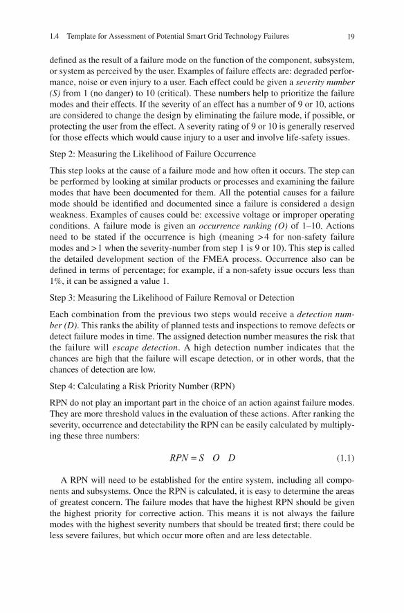
191.4 Template for Assessment of Potential Smart Grid Technology Failures
de fi ned as the result of a failure mode on the function of the component, subsystem, or system as perceived by the user. Examples of failure effects are: degraded perfor-mance, noise or even injury to a user. Each effect could be given a severity number (S) from 1 (no danger) to 10 (critical). These numbers help to prioritize the failure modes and their effects. If the severity of an effect has a number of 9 or 10, actions are considered to change the design by eliminating the failure mode, if possible, or protecting the user from the effect. A severity rating of 9 or 10 is generally reserved for those effects which would cause injury to a user and involve life-safety issues.
Step 2: Measuring the Likelihood of Failure Occurrence
This step looks at the cause of a failure mode and how often it occurs. The step can be performed by looking at similar products or processes and examining the failure modes that have been documented for them. All the potential causes for a failure mode should be identi fi ed and documented since a failure is considered a design weakness. Examples of causes could be: excessive voltage or improper operating conditions. A failure mode is given an occurrence ranking (O) of 1–10. Actions need to be stated if the occurrence is high (meaning > 4 for non-safety failure modes and > 1 when the severity-number from step 1 is 9 or 10). This step is called the detailed development section of the FMEA process. Occurrence also can be de fi ned in terms of percentage; for example, if a non-safety issue occurs less than 1%, it can be assigned a value 1.
Step 3: Measuring the Likelihood of Failure Removal or Detection
Each combination from the previous two steps would receive a detection num-ber (D) . This ranks the ability of planned tests and inspections to remove defects or detect failure modes in time. The assigned detection number measures the risk that the failure will escape detection . A high detection number indicates that the chances are high that the failure will escape detection, or in other words, that the chances of detection are low.
Step 4: Calculating a Risk Priority Number (RPN)
RPN do not play an important part in the choice of an action against failure modes. They are more threshold values in the evaluation of these actions. After ranking the severity, occurrence and detectability the RPN can be easily calculated by multiply-ing these three numbers:
RPN S O D= × × (1.1)
A RPN will need to be established for the entire system, including all compo-nents and subsystems. Once the RPN is calculated, it is easy to determine the areas of greatest concern. The failure modes that have the highest RPN should be given the highest priority for corrective action. This means it is not always the failure modes with the highest severity numbers that should be treated fi rst; there could be less severe failures, but which occur more often and are less detectable.
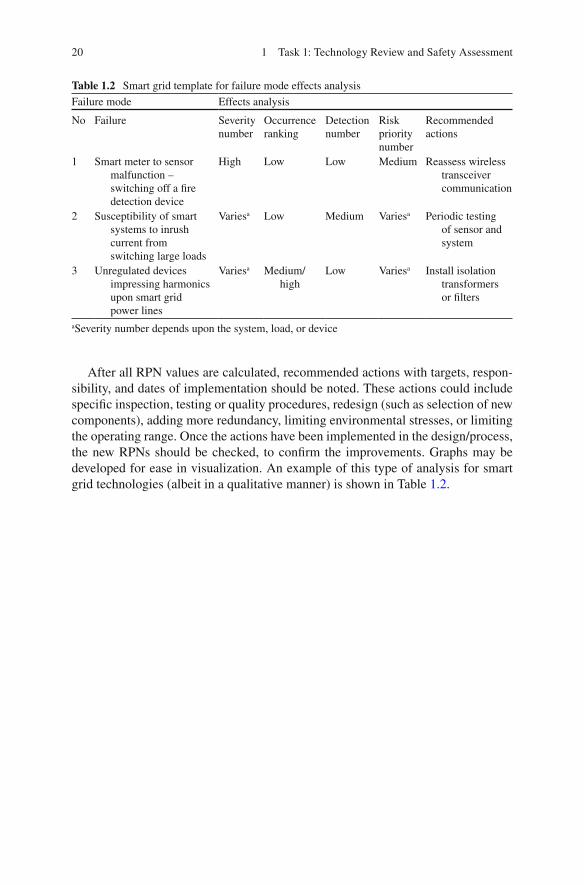
20 1 Task 1: Technology Review and Safety Assessment
Table 1.2 Smart grid template for failure mode effects analysis
Failure mode Effects analysis
No Failure Severity number
Occurrence ranking
Detection number
Risk priority number
Recommended actions
1 Smart meter to sensor malfunction –switching off a fi re detection device
High Low Low Medium Reassess wireless transceiver communication
2 Susceptibility of smart systems to inrush current from switching large loads
Varies a Low Medium Varies a Periodic testing of sensor and system
3 Unregulated devices impressing harmonics upon smart grid power lines
Varies a Medium/high
Low Varies a Install isolation transformers or fi lters
a Severity number depends upon the system, load, or device
After all RPN values are calculated, recommended actions with targets, respon-sibility, and dates of implementation should be noted. These actions could include speci fi c inspection, testing or quality procedures, redesign (such as selection of new components), adding more redundancy, limiting environmental stresses, or limiting the operating range. Once the actions have been implemented in the design/process, the new RPNs should be checked, to con fi rm the improvements. Graphs may be developed for ease in visualization. An example of this type of analysis for smart grid technologies (albeit in a qualitative manner) is shown in Table 1.2 .

21L. Simonian et al., Smart Grid and NFPA Electrical Safety Codes and Standards, SpringerBriefs in Fire, DOI 10.1007/978-1-4614-3948-6_2, © Fire Protection Research Foundation 2011
2.1 Methodology
2.1.1 Background
The potential impact that smart meter technologies have upon safety principals embedded in the NEC was assessed. These safety principles included personnel safety (e.g. shock/electrocution hazards), electrical safety (e.g., potential to damage other electrical/electronic equipment), and fi re safety (e.g., potential to start a fi re). Based upon the results from Task 1, the following areas were identi fi ed:
Dramatic increase in data communication • Grounding and bonding for all components will be needed • Power or control wiring may be required to tie into panelboards/load centers Wiring space in panelboards and other enclosures Sensors will be needed to connect major electrical loads to a smart meter • Susceptibility of smart systems to frequent inrush currents from switching large • appliance loads Accommodations for manual disconnect switches for energy microgeneration, • co-generation, and generation systems Shutoff and/or dummy-load devices for wind power generation • Manual overrides of automatically controlled circuits • Use of direct current by consumers from their EMGS • Conversion of DC generated power into AC • Limiting harmonics that may be introduced into the electric grid by inverters and • other non-linear loads, such as ballasts, etc3. Overcurrent and overload protection • Protection of energy storage systems overcharging • Charging and discharging of ESS • Charge controller for charging storage batteries or other energy storage • Guidelines for the placement of, and clearance requirements for, fuel cells •
Chapter 2 Task 2: Regulatory Review and Gap Assessment

22 2 Task 2: Regulatory Review and Gap Assessment
Load and demand factors will need to be developed or reexamined • Critical circuits for life-safety systems will need to remain powered during load • shedding Charging and discharging of PHEVs, PEVs, and other on-site energy storage • systems Voltage fl icker provisions will need to be reexamined due to the potential increase • in switching loads Guidelines for CES units will need to be developed •
2.1.2 Scope and Approach
A preliminary assessment of gaps and inconsistencies within the U.S. fi re and electrical safety regulatory framework was prepared. The NFPA standards that were reviewed included the following:
NFPA 70, The National Electrical Code • NFPA 70E, Electrical Safety in the Workplace • NFPA 110, Standard for Emergency and Standby Power Systems • NFPA 111, Standard on Stored Electrical Energy Emergency and Standby Power • Systems
In addition, standards referenced by the National Electrical Manufacturers Association (NEMA), Underwriters Laboratories, Inc (UL), the National Institute of Standards and Technology (NIST), and the Institute of Electrical and Electronic Engineers (IEEE) that may affect Smart Grid implementation were identi fi ed.
2.2 Review of NFPA Standards
2.2.1 NFPA 70
Based upon an assessment of current and emerging smart grid technologies, a review of the 2011 edition of NFPA 70 was performed. This review has identi fi ed the following code articles as potential candidates for revision:
2.2.1.1 Introduction
Article 90 Introduction
• 90.2 Scope
“ (A) Covered. This Code covers the installation of electrical conductors, equipment, and raceways; signaling and communications conductors, equip-ment, and raceways; and optical fi ber cables and raceways for the following:
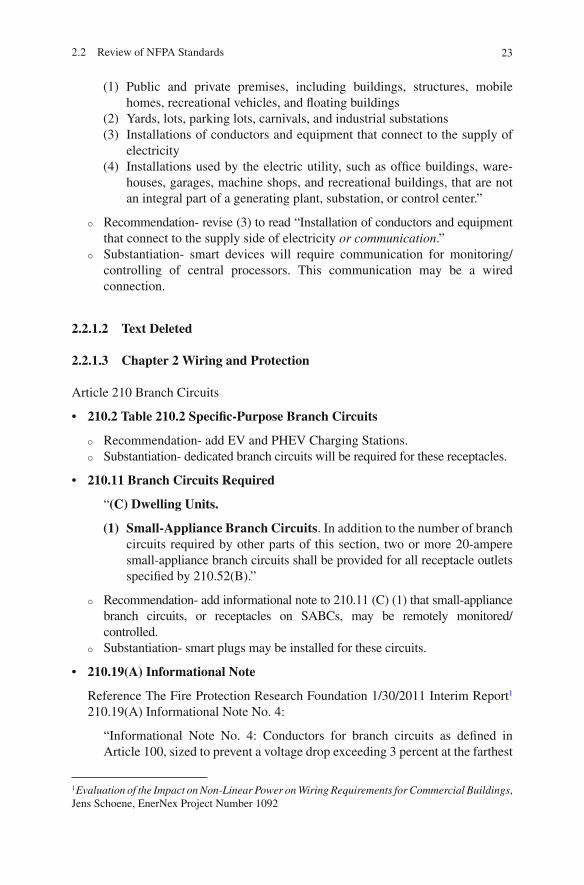
232.2 Review of NFPA Standards
(1) Public and private premises, including buildings, structures, mobile homes, recreational vehicles, and fl oating buildings
(2) Yards, lots, parking lots, carnivals, and industrial substations (3) Installations of conductors and equipment that connect to the supply of
electricity (4) Installations used by the electric utility, such as of fi ce buildings, ware-
houses, garages, machine shops, and recreational buildings, that are not an integral part of a generating plant, substation, or control center.”
Recommendation- revise (3) to read “Installation of conductors and equipment �
that connect to the supply side of electricity or communication .” Substantiation- smart devices will require communication for monitoring/ �
controlling of central processors. This communication may be a wired connection.
2.2.1.2 Text Deleted
2.2.1.3 Chapter 2 Wiring and Protection
Article 210 Branch Circuits
• 210.2 Table 210.2 Speci fi c-Purpose Branch Circuits
Recommendation- add EV and PHEV Charging Stations. �
Substantiation- dedicated branch circuits will be required for these receptacles. �
• 210.11 Branch Circuits Required
“ (C) Dwelling Units.
(1) Small-Appliance Branch Circuits . In addition to the number of branch circuits required by other parts of this section, two or more 20-ampere small-appliance branch circuits shall be provided for all receptacle outlets speci fi ed by 210.52(B).”
Recommendation- add informational note to 210.11 (C) (1) that small-appliance �
branch circuits, or receptacles on SABCs, may be remotely monitored/controlled. Substantiation- smart plugs may be installed for these circuits. �
• 210.19(A) Informational Note
Reference The Fire Protection Research Foundation 1/30/2011 Interim Report 1 210.19(A) Informational Note No. 4:
“Informational Note No. 4: Conductors for branch circuits as de fi ned in Article 100, sized to prevent a voltage drop exceeding 3 percent at the farthest
1 Evaluation of the Impact on Non-Linear Power on Wiring Requirements for Commercial Buildings , Jens Schoene, EnerNex Project Number 1092
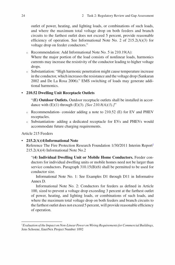
24 2 Task 2: Regulatory Review and Gap Assessment
outlet of power, heating, and lighting loads, or combinations of such loads, and where the maximum total voltage drop on both feeders and branch circuits to the farthest outlet does not exceed 5 percent, provide reasonable ef fi ciency of operation. See Informational Note No. 2 of 215.2(A)(3) for voltage drop on feeder conductors.”
Recommendation: Add Informational Note No. 5 in 210.19(A): �
Where the major portion of the load consists of nonlinear loads, harmonics currents may increase the resistivity of the conductor leading to higher voltage drops. Substantiation: “High harmonic penetration might cause temperature increase �
in the conductor, which increases the resistance and the voltage drop (Sankaran 2002 and De La Rosa 2006).” EMS switching of loads may generate addi-tional harmonics.
• 210.52 Dwelling Unit Receptacle Outlets
“ (E) Outdoor Outlets. Outdoor receptacle outlets shall be installed in accor-dance with (E)(1) through (E)(3). [See 210.8(A)(3).] ”
Recommendation- consider adding a note to 210.52 (E) for EV and PHEV �
receptacles. Substantiation- adding a dedicated receptacle for EVs and PHEVs would �
accommodate future charging requirements.
Article 215 Feeders
• 215.2(A)(4)Informational Note Reference The Fire Protection Research Foundation 1/30/2011 Interim Report 2 215.2(A)(4) Informational Note No.2
“ (4) Individual Dwelling Unit or Mobile Home Conductors. Feeder con-ductors for individual dwelling units or mobile homes need not be larger than service conductors. Paragraph 310.15(B)(6) shall be permitted to be used for conductor size.
Informational Note No. 1: See Examples D1 through D11 in Informative Annex D.
Informational Note No. 2: Conductors for feeders as de fi ned in Article 100, sized to prevent a voltage drop exceeding 3 percent at the farthest outlet of power, heating, and lighting loads, or combinations of such loads, and where the maximum total voltage drop on both feeders and branch circuits to the farthest outlet does not exceed 5 percent, will provide reasonable ef fi ciency of operation.
2 Evaluation of the Impact on Non-Linear Power on Wiring Requirements for Commercial Buildings , Jens Schoene, EnerNex Project Number 1092
252.2 Review of NFPA Standards
Informational Note No. 3: See 210.19(A), Informational Note No. 4, for voltage drop for branch circuits.”
Recommendation: Add Informational Note No. 4 in 215.2(A)(4): �
Where the major portion of the load consists of nonlinear loads, harmonics currents may increase the resistivity of the conductor leading to higher voltage drops. Substantiation: High harmonic penetration might cause temperature increase �
in the conductor, which increases the resistance and the voltage drop (Sankaran 2002 and De La Rosa 2006).” EMS switching of loads may generate additional harmonics.
Article 220 Branch Circuit, Feeder, and Service Calculations
• 220.3 Table 220.3 Additional Load Calculation References
Recommendation- add wind power systems, fuel cell systems, EV and PHEV �
charging stations, and CES. Substantiation- another micro generation system (photovoltaic) is currently �
listed as are specialty devices and equipment.
• 220.14 Other Loads—All Occupancies
“ (L) Other Outlets. Other outlets not covered in 220.14(A) through (K) shall be calculated based on 180 volt-amperes per outlet.”
Recommendation- add 220.14 (M) EV and PHEV Receptacles Outlets. An �
outlet for EV and PHEV shall be calculated based on the ampere rating of the EV and PHEV equipment served. Substantiation- minimum load requirements should be speci fi ed. �
• 220.44 Receptacle Loads—Other Than Dwelling Units
Recommendation- consider adding Commercial EV and PHEV charging �
stations to Table 220.44. Substantiation- this will address load demand factors for equipment. �
Article 230 Services
• 230.82 Equipment Connected to the Supply Side of Service Disconnect
“(6) Solar photovoltaic systems, fuel cell systems, or interconnected electric power production sources.”
Recommendation- add wind power systems to 230.82 (6) � OR delete refer-ences to solar photovoltaic systems and fuel cell systems, and refer to all of these systems as “alternate power sources.” Substantiation- code section currently lists solar photovoltaic and fuel cell �
systems; either all new generation systems should be listed or these systems should be collectively referenced.
26 2 Task 2: Regulatory Review and Gap Assessment
Article 240 Overcurrent Protection
• 240.3 Table 240.3 Other Articles
Recommendation- add wind power systems (694), fuel cell systems (692), �
EV and PHEV charging stations (625), and CES. Substantiation- another micro generation system (photovoltaic) is currently �
listed as are specialty devices and equipment.
Article 250 Grounding and Bonding
• 250.3 Table 250.3 Additional Grounding and Bonding Requirements
Recommendation- add wind power systems, fuel cell systems, EV and PHEV �
charging stations, and CES. Substantiation- another micro generation system (photovoltaic) is currently �
listed as are specialty devices and equipment.
2.2.1.4 Chapter 4 Equipment for General Use
Article 422 Appliances
• 422.31 Disconnection of Permanently Connected Appliances
“ (A) Rated at Not over 300 Volt-Amperes or 1⁄8 Horsepower. For perma-nently connected appliances rated at not over 300 volt-amperes or 1⁄8 hp, the branch-circuit overcurrent device shall be permitted to serve as the discon-necting means. (B) Appliances Rated over 300 Volt-Amperes. For permanently connected appliances rated over 300 voltamperes, the branch-circuit switch or circuit breaker shall be permitted to serve as the disconnecting means where the switch or circuit breaker is within sight from the appliance or is capable of being locked in the open position. The provision for locking or adding a lock to the disconnecting means shall be installed on or at the switch or circuit breaker used as the disconnecting means and shall remain in place with or without the lock installed.
Informational Note: For appliances employing unit switches, see 422.34. (C) Motor-Operated Appliances Rated over 1⁄8 Horsepower.
For permanently connected motor-operated appliances with motors rated over 1⁄8 horse power, the branch circuit switch or circuit breaker shall be per-mitted to serve as the disconnecting means where the switch or circuit breaker is within sight from the appliance. The disconnecting means shall comply with 430.109 and 430.110.
Exception: If an appliance of more than 1⁄8 hp is provided with a unit switch that complies with 422.34(A), (B), (C), or (D), the switch or circuit breaker serving as the other disconnecting means shall be permitted to be out of sight from the appliance. ”

272.2 Review of NFPA Standards
Recommendation- augment 422.31 (A), (B), and (C) for capability to com- �
municate with smart meter and EMS to both sense power status and remotely control/disconnect appliance. Substantiation- speci fi c appliances may be remotely monitored and/or con- �
trolled to power-up or -down depending upon the kWh cost of electricity.
Article 424 Fixed Electric Space-Heating Equipment
• 424.19 Disconnecting Means
“Means shall be provided to simultaneously disconnect the heater, motor controller(s), and supplementary overcurrent protective device(s) of all fi xed electric space-heating equipment from all ungrounded conductors. Where heating equipment is supplied by more than one source, the disconnecting means shall be grouped and marked. The disconnecting means speci fi ed in 424.19(A) and (B) shall have an ampere rating not less than 125 percent of the total load of the motors and the heaters. The provision for locking or adding a lock to the disconnecting means shall be installed on or at the switch or circuit breaker used as the disconnecting means and shall remain in place with or without the lock installed.”
Recommendation- augment 424.19 for capability to communicate with smart �
meter and EMS to both sense power status and remotely disconnect space-heating equipment. Substantiation- speci fi c space-heating equipment may be remotely monitored and/ �
or controlled to power-up or -down depending upon the kWh cost of electricity.
Article 430 Motors, Motor Circuits, and Controllers
• 430.75 Disconnection
“ (A) General. Motor control circuits shall be arranged so that they will be disconnected from all sources of supply when the disconnecting means is in the open position. The disconnecting means shall be permitted to consist of two or more separate devices, one of which disconnects the motor and the controller from the source(s) of power supply for the motor, and the other(s), the motor control circuit(s) from its power supply. Where separate devices are used, they shall be located immediately adjacent to each other.
Exception No. 1: Where more than 12 motor control circuit conductors are required to be disconnected, the disconnecting means shall be permitted to be located other than immediately adjacent to each other where all of the following conditions are complied with:
(a) Access to energized parts is limited to quali fi ed persons in accordance with Part XII of this article.
(b) A warning sign is permanently located on the outside of each equipment enclosure door or cover permitting access to the live parts in the motor control circuit(s), warning that motor control circuit disconnecting means
28 2 Task 2: Regulatory Review and Gap Assessment
are remotely located and specifying the location and identi fi cation of each disconnect. Where energized parts are not in an equipment enclosure as permitted by 430.232 and 430.233, an additional warning sign(s) shall be located where visible to persons who may be working in the area of the energized parts.
Exception No. 2: The motor control circuit disconnecting means shall be permitted to be remote from the motor controller power supply discon-necting means where the opening of one or more motor control circuit disconnecting means is capable of resulting in potentially unsafe condi-tions for personnel or property and the conditions of items (a) and (b) of Exception No. 1 are complied with. ”
Recommendation- augment 430.75 for capability to communicate with smart �
meter and EMS to both sense power status and remotely disconnect an indi-vidual motor. Substantiation- speci fi c motors may be remotely monitored and/or controlled �
to power-up or -down depending upon the kWh cost of electricity.
Article 440 Air-Conditioning and Refrigeration Equipment
• 440.11 Disconnecting Means, General
“The provisions of Part II are intended to require disconnecting means capable of disconnecting air conditioning and refrigerating equipment, including motor compressors and controllers from the circuit conductors.”
Recommendation- augment 440.11 for capability to communicate with smart �
meter and EMS to both sense power status and remotely disconnect AC/Refrigeration equipment. Substantiation- speci fi c equipment may be remotely monitored and/or con- �
trolled to power-up or -down depending upon the kWh cost of electricity.
Article 445 Generators
• 445.18 Disconnecting Means Required for Generators
“Generators shall be equipped with disconnect(s), lockable in the open posi-tion, by means of which the generator and all protective devices and control apparatus are able to be disconnected entirely from the circuits supplied by the generator except where both of the following conditions apply:
(1) The driving means for the generator can be readily shut down. (2) The generator is not arranged to operate in parallel with another genera-
tor or other source of voltage.”
Recommendation- augment 445.18 for capability to communicate with smart �
meter and EMS to both sense power status and remotely start/stop on-site generators. Substantiation- on-site generation may be remotely controlled to power-up �
or -down depending upon the kWh cost of electricity.

292.2 Review of NFPA Standards
Article 480 Storage Batteries
• 480.5 Disconnecting Means
“A disconnecting means shall be provided for all ungrounded conductors derived from a stationary battery system over 50 volts. A disconnecting means shall be readily accessible and located within sight of the battery system.
Informational Note: See 240.21(H) for information on the location of the overcurrent device for battery conductors.”
Recommendation- augment 480.5 for capability to communicate with smart �
meter and EMS to both sense power status and remotely charge or discharge batteries, unless the storage battery systems are critical for continuity of essential services or systems. Substantiation- on-site battery storage systems may be remotely controlled to �
power-up or -down depending upon the kWh cost of electricity.
2.2.1.5 Chapter 5 Special Occupancies
Article 517 Health Care Facilities
• 517.31 Scope—Emergency Systems
“Those functions of patient care depending on lighting or appliances that are connected to the emergency system shall be divided into two mandatory branches: the life safety branch and the critical branch, described in 517.32 and 517.33. The branches of the emergency system shall be installed and connected to the alternate power source so that all functions speci fi ed herein for the emergency system shall be automatically restored to operation within 10 seconds after interruption of the normal source. [ 99: 4.4.2.2.2.1, 4.4.3.1]”
Recommendation- amend section to ensure that both life safety and critical �
branches remain powered during load shedding Substantiation- EMS initialed load shedding to be integrated with emergency �
electrical distribution system including on-site generation.
2.2.1.6 Chapter 6 Special Equipment
Article 625 Electric Vehicle Charging Stations
• 625.26 Interactive Systems
“Electric vehicle supply equipment and other parts of a system, either on-board or off-board the vehicle, that are identi fi ed for and intended to be intercon-nected to a vehicle and also serve as an optional standby system or an electric power production source or provide for bi-directional power feed shall be listed as suitable for that purpose. When used as an optional standby system, the requirements of Article 702 shall apply, and when used as an electric power production source, the requirements of Article 705 shall apply.”
30 2 Task 2: Regulatory Review and Gap Assessment
Recommendation- add Information Note #1 that expands upon the role of �
EVs and PHEVs to communicate with a smart meter and EMS to both sense power status and remotely enable the EV/PHEV to be an electric power production source Substantiation- EVs/PHEVs may be remotely monitored and/or controlled �
to charge or discharge depending upon the kWh cost of electricity
2.2.1.7 Chapter 7 Special Conditions
Article 700 Emergency Systems
• 700.4 Capacity 3
“ (A) Capacity and Rating. An emergency system shall have adequate capacity and rating for all loads to be operated simultaneously. The emer-gency system equipment shall be suitable for the maximum available fault current at its terminals. (B) Selective Load Pickup, Load Shedding, and Peak Load Shaving. The alternate power source shall be permitted to supply emergency, legally required standby, and optional standby system loads where the source has adequate capacity or where automatic selective load pickup and load shedding is provided as needed to ensure adequate power to (1) the emergency circuits, (2) the legally required standby circuits, and (3) the optional standby circuits, in that order of priority. The alternate power source shall be permitted to be used for peak load shaving, provided these conditions are met.
Peak load shaving operation shall be permitted for satisfying the test requirement of 700.3(B), provided all other conditions of 700.3 are met.”
Recommendation- amend 700.4 (B) to include safeguards, such as requiring a �
different EMS, against the emergency system being treated as a regular system for the purposes of load shedding. Substantiation- other non-emergency circuits in the facility may have load shed- �
ding or other energy management capabilities that should be triggered under different conditions then emergency systems
2.2.7.2 Article 701 Legally Required Standby Systems
• 701.4 Capacity and Rating 4
“A legally required standby system shall have adequate capacity and rating for the supply of all equipment intended to be operated at one time. Legally required standby system equipment shall be suitable for the maximum available fault current at its terminals.
3 Smart Grid Task Force meeting March 3, 2011 4 Smart Grid Task Force meeting March 3, 2011
312.2 Review of NFPA Standards
The legally required standby alternate power source shall be permitted to supply both legally required standby and optional standby system loads under either of the following conditions:
(1) Where the alternate source has adequate capacity to handle all connected loads
(2) Where automatic selective load pickup and load shedding is provided that will ensure adequate power to the legally required standby circuits.”
Recommendation- amend 701.4 to clarify if the standby system may be �
used for other purposes, such as peak load shaving, similar to 700.4 (B). Alternatively, reference the article, such as 705, under which these issues are addressed. If other uses are allowed, the recommendation is also to include safeguards, such as a different EMS, against the emergency system being treated as a regular system for the purposes of load shedding. Substantiation- other non-emergency circuits in the facility may have load �
shedding or other energy management capabilities that should be triggered under different conditions then legally required standby systems
Article 705 Interconnected Electrical Power Production Systems
Recommendation- add a subsection to article 705 to address smart grid �
switching capabilities 5 Substantiation- proliferation of smart grid technologies, such as EMS, �
increase the chance that additional energy sources will be controlled by a separate system
• Table 705.3 Other Articles
Recommendation- amend Table 705.3 to include other emerging production �
sources such as wind generation as they are addressed. Small Wind Electric systems are addressed in Article 694. Substantiation- smart grid enhancements may make interconnected power �
systems more common
• 705.20 Disconnecting Means, Sources 6
“Means shall be provided to disconnect all ungrounded conductors of an electric power production source(s) from all other conductors.”
Recommendation- amend 705.20 or add an article to include a lock-out-tag-out �
system for EMS or other smart grid technology controlled generation systems Substantiation- smart grid systems, such as an EMS, may be in control of �
grid-tied generation systems, so means must be provided to assure service personnel that generation systems won’t energize circuits when undesired
5 Smart Grid Task Force meeting March 3, 2011 6 Smart Grid Task Force meeting March 3, 2011

32 2 Task 2: Regulatory Review and Gap Assessment
• 705.30 Overcurrent Protection 7
“Conductors shall be protected in accordance with Article 240. Equipment and conductors connected to more than one electrical source shall have a suf fi cient number of overcurrent devices located so as to provide protection from all sources.
(A) Solar Photovoltaic Systems. Solar photovoltaic systems shall be protected in accordance with Article 690. (B) Transformers. Overcurrent protection for a transformer with a source(s) on each side shall be provided in accordance with 450.3 by considering fi rst one side of the transformer, then the other side of the transformer, as the primary. (C) Fuel Cell Systems. Fuel cell systems shall be protected in accordance with Article 692. (D) Utility-Interactive Inverters. Utility-interactive inverters shall be pro-tected in accordance with 705.65. (E) Generators. Generators shall be protected in accordance with 705.130.”
Recommendation- add additional letter items, (F), (G), etc., to include other �
emerging production sources such as wind generation. See Table 705.3 recommendations above
Substantiation- smart grid enhancements may make interconnected power sys- �
tems more common
• 705.40 Loss of Primary Source
“Upon loss of primary source, an electric power production source shall be automatically disconnected from all ungrounded conductors of the primary source and shall not be reconnected until the primary source is restored.
Exception: A listed utility-interactive inverter shall be permitted to automati-cally cease exporting power upon loss of primary source and shall not be required to automatically disconnect all ungrounded conductors from the primary source. A listed utility-interactive inverter shall be permitted to automatically or manually resume exporting power to the utility once the primary source is restored.
Informational Note No. 1: Risks to personnel and equipment associated with the primary source could occur if an utility interactive electric power produc-tion source can operate as an intentional island. Special detection methods are required to determine that a primary source supply system outage has occurred and whether there should be automatic disconnection. When the primary source supply system is restored, special detection methods can be required to limit exposure of power production sources to out-of-phase reconnection.
7 Smart Grid Task Force meeting March 3, 2011
332.2 Review of NFPA Standards
Informational Note No. 2: Induction-generating equipment on systems with signi fi cant capacitance can become self-excited upon loss of the primary source and experience severe overvoltage as a result. A utility-interactive inverter shall be permitted to operate as a stand-alone system to supply loads that have been disconnected from electrical production and distribution network sources.”
Recommendation- amend 705.40 to add scenarios as appropriate to include �
actions that should be taken by an EMS or other smart grid switching sys-tem in the event of a power loss Substantiation- smart grid systems, such as an EMS, may be in control of �
grid-tied generation systems
Article 708 Critical Operations Power Systems (COPS)
• 708.22 Capacity of Power Sources
“ (A) Capacity and Rating. A COPS shall have capacity and rating for all loads to be operated simultaneously for continuous operation with variable load for an unlimited number of hours, except for required maintenance of the power source. A portable, temporary, or redundant alternate power source shall be available for use whenever the COPS power source is out of service for maintenance or repair. (B) Selective Load Pickup, Load Shedding, and Peak Load Shaving. The alternate power source shall be permitted to supply COPS emergency, legally required standby, and optional loads where the source has adequate capacity or where automatic selective load pickup and load shedding is provided as needed to ensure adequate power to (1) the COPS and emergency circuits, (2) the legally required standby circuits, and (3) the optional standby circuits, in that order of priority. The alternate power source shall be permitted to be used for peak load shaving, provided these conditions are met.
Peak load-shaving operation shall be permitted for satisfying the test requirement of 708.6(B), provided all other conditions of 708.6 are met. (C) Duration of COPS Operation. The alternate power source shall be capa-ble of operating the COPS for a minimum of 72 hours at full load of DCOA with a steady-state voltage within ±10 percent of nominal utilization voltage.”
Recommendation- amend 708.22 (B) to include safeguards, such as a �
different EMS, against the emergency system being treated as a regular system for the purposes of load shedding. Substantiation- other non-emergency circuits in the facility may have load shed- �
ding or other energy management capabilities that should be triggered under different conditions then COPS
Add an Article 750: Energy Management and Load Management Systems
Recommendation- consider adding a new article that references code and �
rules for EMS and other load management systems Substantiation- smart grid proliferation may make EMS more common �
34 2 Task 2: Regulatory Review and Gap Assessment
2.2.2 NFPA 70E
Based upon an assessment of current and emerging smart grid technologies, a review of the 2009 edition of NFPA 70E was conducted and the following sections were identi fi ed as candidates for revision.
2.2.2.1 Chapter 1 General
Article 100 De fi nitions
• Community Energy Storage (CES)
Recommendation- add reference to Community Energy Storage (CES): small �
battery-based energy storage units\ connected to a utility transformers’ secondary coil with storage capacity available to more than one customer with limited back-up time. Substantiation- CES is an emerging smart grid storage technology. �
• Electric Thermal Storage (ETS) Recommendation- add reference to ETS: conversion of electric energy into �
heat and storing it in high-mass units, or bricks, made of dense ceramic material. Substantiation- currently in-use in the residential sector. �
• Energy Monitoring and Control System (EMCS), Energy Management System (EMS), and Energy Information System (EIS)
Recommendation- add reference to EMCS, EMS, and EIS: systems which �
monitor energy consumption and may also have the capability to control energy usage. Substantiation- EMCS, EMS, and EIS are all in current use in commercial �
applications and will become more common in residential settings.
• Electric Vehicle (EV) and Plug-in Hybrid Electric Vehicle (PHEV) Charging Station
Recommendation- add reference to EV and PHEV charging stations: recep- �
tacle assembly including all supporting equipment for the purpose of charging EVs and PHEVs. Substantiation- EV and PHEV charging stations are becoming more common �
in commercial applications.
• Fuel Cell Generation
Recommendation- add reference to fuel cells: an electrochemical cell that �
converts a source fuel into an electric current. Substantiation- fossil fuel based fuel cells are in current use. �

352.2 Review of NFPA Standards
• Photovoltaic (PV) Generation
Recommendation- add reference to PVs: a method of generating electrical �
power by converting solar radiation into direct current electricity using semiconductors that exhibit a photovoltaic effect. Substantiation- PVs are commonly used. �
• Smart Meters
Recommendation- add reference to Smart Meter: an advanced electric meter �
that records consumption in intervals of 1 h or less and communicates that information at least daily via some communications network back to the utility for monitoring and billing purposes (telemetering). Substantiation- Smart Meters are in general use. �
• Smart Plugs, Smart Power Strips
Recommendation- add reference to smart plugs/power strips: receptacles �
which are able to monitor and control the fl ow of electricity between a power outlet and connected devices. Substantiation- smart plugs/power strips are an emerging technology within �
the data processing sector.
• Thermal Energy Storage (TES)
Recommendation- add reference to TES: creating ice at night when electricity �
is usually less costly, and then using the ice to cool the air in buildings during the hotter daytime periods. Substantiation- currently in-use in the commercial sector. �
• Wind Power Generation
Recommendation- add reference to wind power generation: wind turbines �
which provide a means for the conversion of wind energy into electricity. Substantiation- currently in-use in residential and commercial sectors. �
Article 120 Establishing an Electrically Safe Work Condition
• 120.1 Process of Achieving an Electrically Safe Work Condition
Recommendation- add (7): Disconnecting means to be provided to disconnect/ �
isolate electrical equipment and the potential personnel hazards from equip-ment that may be operated remotely. Substantiation- on-site generation may be remotely controlled to power-up �
or -down depending upon the kWh cost of electricity.

36 2 Task 2: Regulatory Review and Gap Assessment
2.2.2.2 Chapter 3 Safety Requirements for Special Equipment
Article 320 Safety Requirements Related to Batteries and Battery Rooms
• 320.3 (H) (1) (1) Abnormal Battery Connections for vented batteries
Recommendation- add (e): Alarm condition for overcharging. �
Substantiation- Frequent charging/discharging of batteries due to increased �
supply of power to the grid may result in overcharging conditions.
2.2.3 NFPA 110
Based upon an assessment of current and emerging smart grid technologies, a review of the 2010 edition of NFPA 110 was conducted and the following sections were identi fi ed as candidates for revision.
2.2.3.1 Chapter 5 Emergency Power Supply: Energy Sources, Converters, and Accessories
Article 5.2 Energy Converters—General
• 5.2.1 Energy Converters
“Energy converters shall consist only of rotating equipment as indicated in 5.2.4”
Recommendation- add explanatory material or clari fi cation to address fuel cells. �
Substantiation- fuel cells are permitted as emergency system power sources �
in NFPA 70—700.12 (E).
2.2.3.2 Chapter 6 Transfer Switch Equipment
The recommendations in chapter 6 depend upon the level and response time of communication provided by a smart meter, EMS, and/or other communication devices, and assume the primary source of power is off-site, such as a utility. Should the necessary communication abilities become common, then the following recom-mendations are made.
Section 6.2.2 Source Monitoring
• 6.2.2.1
“ * Undervoltage-sensing devices shall be provided to monitor all ungrounded lines of the primary source of power as follows:
(1) When the voltage on any phase falls below the minimum operating voltage of any load to be served, the transfer switch shall automatically initiate engine start and the process of transfer to the EPS.

372.2 Review of NFPA Standards
(2) *When the voltage on all phases of the primary source returns to within speci fi ed limits for a designated period of time, the process of transfer back to primary power shall be initiated.”
Recommendation 1- augment 6.2.2.1 to include a provision for the transfer �
switch initiating engine start upon a signal from the primary source provider indicating that primary source failure will occur. Recommendation 2- augment 6.2.2.1 for capability to communicate with �
smart meter and EMS to both sense power status and remotely start/stop EPS. Substantiation 1- the utility may be able to provide early warning of failure, �
allowing the EPS to activate earlier. Substantiation 2- EPS may be remotely controlled to power-up or -down �
depending upon the kWh cost of electricity.
Section 6.2.5 Time Delay on Starting of EPS
• 6.2.5 Time Delay on Starting of EPS
“A time-delay device shall be provided to delay starting of the EPS. The timer shall prevent nuisance starting of the EPS and possible subsequent load transfer in the event of harmless momentary power dips and interruptions of the primary source.”
Recommendation- augment 6.2.5 to include a provision for additional delay �
of EPS start when a signal from the primary source provider is received that indicates that the abnormal source condition, such as a voltage drop, is a tem-porary condition that will be resolved within a prescribed time period. Substantiation- an additional safeguard against nuisance starting of the EPS. �
2.2.4 NFPA 111
Based upon an assessment of current and emerging smart grid technologies, a review of the 2010 edition of NFPA 111 was conducted and the following sections were identi fi ed as candidates for revision.
2.2.4.1 Chapter 6 Transfer Switches and Protection
The recommendations in Chap. 6 depend upon the level and response time of communication provided by a smart meter, EMS, and/or other communication devices, and assume the primary source of power is off-site, such as a utility. Should the necessary communication abilities become common, then the following recom-mendations are made.
38 2 Task 2: Regulatory Review and Gap Assessment
Section 6.2.4.2 Source Monitoring
• 6.2.4.2* Source Monitoring
“ 6.2.4.2* Source Monitoring. The load source shall be monitored for under-voltage and overvoltage on all of its ungrounded input lines. 6.2.4.2.1 The ECE and the utility shall be monitored for unacceptable conditions.”
Recommendation 1- augment 6.2.4.2 to include a provision for the transfer �
switch initiating engine start upon a signal from the primary source provider indicating that primary source failure will occur. Recommendation 2- augment 6.2.4.2 for capability to communicate with �
smart meter and EMS to both sense power status and remotely start/stop SEPS. Substantiation 1- the utility may be able to provide early warning of failure, �
allowing the SEPS to activate earlier. Substantiation 2- SEPS may be remotely controlled to power-up or -down �
depending upon the kWh cost of electricity (if SEPSs are permitted for such use, see Sect. 2.2.4.2 of this document.)
• 6.2.4.2.4
6.2.4.2.4 An adjustable time delay shall be allowed to ensure that the pre-ferred source is within its steady-state speci fi cation limits before such retrans-fer is performed.”
Recommendation- augment 6.2.4.2 to include a provision for additional delay �
of SEPS retransfer to preferred source upon signal from the preferred source that such stabilization time is necessary. Substantiation- additional safeguard to keep preferred source from being �
overwhelmed.
Section 6.2.4.5 Time Delay on Retransfer to Preferred Source
• 6.2.4.5* Time Delay on Retransfer to Preferred Source
“ 6.2.4.5.1 An adjustable time delay device with automatic bypass shall be provided to delay retransfer from the alternate source to the preferred source of power. 6.2.4.5.2 The time delay shall be automatically bypassed if the ECE or EPS fails.”
Recommendation- add a 6.2.4.5.2 that extends the delay at the request of the �
preferred source. Substantiation- provides additional time as needed for the stabilization of �
the preferred source.
392.3 Identification of Other Standards
2.2.4.2 Chapter 7 Installation and Environmental Consideration
Section 7.1 General
• 7.1.4
“ 7.1.4 Where normal power is available, the EPS shall serve Level 1 and Level 2 system loads and shall be permitted to serve additional loads, provided that, on failure of the normal power, the additional loads are auto-matically dropped to ensure that the EPS has suf fi cient capacity to serve the Level 1 and Level 2 loads.”
Recommendation- add a 7.1.5 or augment 7.1.4 to clarify if the SEPS is �
permitted to be used for load relief and peak shaving, similar to NFPA 110 7.1.5. Substantiation- clari fi es if the SEPS may be used in a similar manner to an �
EPS when normal power is available. Evolving energy storage technologies combined with time of use rates may make this a fi nancially attractive option to SEPS owners.
2.2.4.3 Chapter 8 Routine Maintenance and Operational Testing
Section 8.4 Operational Inspection and Testing
• 8.4 Operational Inspection and Testing
“ 8.4.1* Level 1 equipment shall be inspected monthly and tested in accordance with the manufacturer’s recommendations. (See Figure A.8.4.2.) ”
Recommendation- add 8.4.1.1 to address the permissibility of substituting �
peak shaving or load relief operations, if permitted (see Sect. 2.2.4.2 of this document), in lieu of mandated load testing, similar to NFPA 110 8.4.1.1. Substantiation- clari fi es if an SEPS may be used in a similar manner to an �
EPS regarding load testing.
2.3 Identi fi cation of Other Standards
2.3.1 National Electrical Manufacturers Association (NEMA)
ANSI C12.1-2008 American National Standard for Electric Meters—Code for • Electricity Metering ANSI C12.22-2008 American National Standard for Protocol Speci fi cation for • Interfacing to Data Communication Networks
40 2 Task 2: Regulatory Review and Gap Assessment
ANSI C82.77-2002 American National Standard for Harmonic Emission • Limits—Related Power Quality Requirements for Lighting Equipment NEMA 410-2004 Performance Testing for Lighting Controls and Switching • Devices with Electronic Fluorescent Ballasts NEMA DC 3-2008 Residential Controls—Electrical Wall-Mounted Room • Thermostats NEMA DC 5-1989 (R1996, R2002, R2008) Residential Controls—Surface-Type • Controls for Electric Storage Water Heaters NEMA DC 10-2009 Residential Controls—Temperature Limit Controls for • Electric Baseboard Heaters NEMA DC 13-1979 (R1985, R1991, R1997, R2002, R2008) Residential • Controls—Line Voltage Integrally Mounted Thermostats for Electric Heaters NEMA ICS 10-2005, Part 1: Electromechanical AC Transfer Switch • Equipment NEMA LSD 53-2010 Proposal for Digital Protocol for Lighting Control • Devices NEMA PE 1-2003 Uninterruptible Power Systems (UPS)—Speci fi cation and • Performance Veri fi cation NEMA SG-AMI 1-2009 Requirements for Smart Meter Upgradeability • NEMA TP 2-2005 Standard Test Method for Measuring the Energy Consumption • of Distribution Transformers NEMA WD 7-2000 (R2005) Occupancy Motion Sensors • NTCIP 2001:1996 National Transportation Communications For ITS Protocol—• Class B Pro fi le
2.3.2 Underwriters Laboratories, Inc (UL)
UL 231 Standard for Power Outlets • UL 244A Standard for Solid-State Controls for Appliances • UL 489B Molded-Case Circuit Breakers, Molded-Case Switches, and Circuit-• Breaker Enclosures for use with Photovoltaic (PV) Systems UL 916 Standard for Energy Management Equipment • UL 1077 Standard for Supplementary Protectors for Use in Electrical • Equipment UL 1279 Solar Collectors • UL 1703 Standard for Flat-Plate Photovoltaic Modules and Panels • UL 1778 Uninterruptible Power Systems • UL 2202 Standard for Electric Vehicle (EV) Charging System Equipment • UL 2231, Standard for Personnel Protection Systems for Electric Vehicle (EV) • Supply Circuits UL 2251 Standard for Plugs, Receptacles and Couplers for Electric Vehicles • UL 2262 PEM Type Fuel Cell Power Plants/Modules • UL 2264B Hydrogen Generators using Water Reaction •
412.3 Identification of Other Standards
UL 2267 Standard for Fuel Cell Power Systems for Installation in Industrial • Electric Trucks UL 2271 Batteries for use in Light Electric Vehicle (LEV) Applications • UL 2594 Electric Vehicle Supply Equipment • UL 2735 Electric Utility Meters • UL 6140 Wind Turbine Generating Systems • UL 6141 Wind Turbine Converters and Interconnection Systems Equipment • UL 60730 Automatic Electrical Controls for Household and Similar Use; • Parts 1 and 2 UL 61058-1 Switches for Appliances—Part 1: General Requirements •
2.3.3 National Institute of Standards and Technology (NIST) Priority Action Plans (PAPS)
PAP 1 Role of IP in the Smart Grid • PAP 2 Wireless Communications for the Smart Grid • PAP 5 Standard Meter Data Pro fi les • PAP 7 Energy Storage interconnection Guidelines • PAP 8 CIM for Distribution Grid Management • PAP09: Standard DR and DER Signals • PAP10: Standard Energy Usage Information • PAP11: Common Object Models for Electric Transportation • PAP15: Harmonize Power Line Carrier Standards for Appliance Communications • in the Home PAP16: Wind Plant Communications • PAP17: Facility Smart Grid Information Standard •
2.3.4 Institute of Electrical and Electronic Engineers (IEEE)
2.3.4.1 Existing Standards
IEEE 519 1992 Recommended Practices and Requirements for Harmonic Control in Electrical Power Systems
IEEE 1159 2009 Recommended Practice for Monitoring Electric Power Quality IEEE 1547 Standard for Interconnecting Distributed Resources with Electric
Power Systems
IEEE 1547.1 2005 Standard for Conformance Tests Procedures for Equipment • Interconnecting Distributed Resources with Electric Power Systems IEEE 1547.2 Application Guide for IEEE 1547 Standard for Interconnecting • Distributed Resources with Electric Power Systems
42 2 Task 2: Regulatory Review and Gap Assessment
IEEE 1547.3 2007 Guide For Monitoring, Information Exchange, and Control of • Distributed Resources Interconnected with Electric Power Systems IEEE P1547.4 Draft Guide for Design, Operation, and Integration of Distributed • Resource Island Systems with Electric Power Systems IEEE P1547.5 Draft Technical Guidelines for Interconnection of Electric Power • Sources Greater than 10MVA to the Power Transmission Grid IEEE P1547.6 Draft Recommended Practice For Interconnecting Distributed • Resources With Electric Power Systems Distribution Secondary Networks IEEE P1547.7 Draft Guide to Conducting Distribution Impact Studies for • Distributed Resource Interconnection IEEE P1547.8 Recommended Practice for Establishing Methods and Procedures • that Provide Supplemental Support for Implementation Strategies for Expanded Use of IEEE Standard 1547
IEC 61000-3-2 Electromagnetic Compatibility (EMC)—Part 3–2: Limits for harmonic current emissions (equipment input current < = 16 A per phase)
IEC 61000-3-12 Electromagnetic compatibility (EMC)—Part 3–12: Limits for harmonic currents produced by equipment connected to public low-voltage systems with input current >16 A and < =75 A per phase
2.3.4.2 IEEE Foundations for Smart Grid Standards (in Development)
IEEE Standard 762: Standard De fi nitions for Use in Reporting Electric Generating Unit Reliability, Availability, and Productivity
IEEE 802 LAN/MAN Standards Series IEEE Standard 1159 for Monitoring Electric Power Quality IEEE SCC 31 Automatic Meter Reading and Related Services IEEE P2030 Draft Guide for Smart Grid Interoperability of Energy Technology
and Information Technology Operation with the Electric Power System (EPS), and End-Use Applications and Loads
2.3.4.3 IEEE Proposed Standards
IEEE Integration of Renewable Energy into the Transmission and Distribution • Grids IEEE Wind and Solar Plant Collector Design Working Group •
2.4 Assessment of Gaps/Inconsistencies
Table 2.1
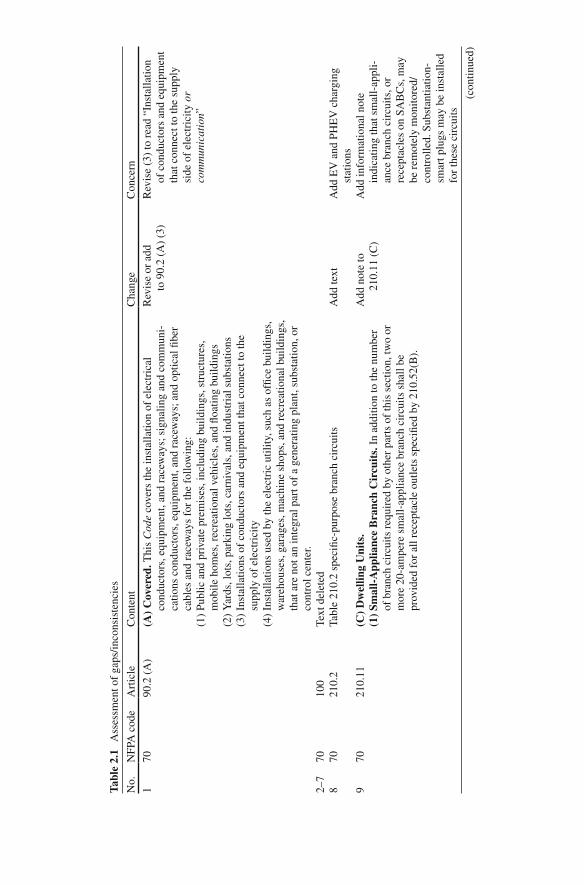
Tabl
e 2.
1 A
sses
smen
t of
gaps
/inco
nsis
tenc
ies
No.
N
FPA
cod
e A
rtic
le
Con
tent
C
hang
e C
once
rn
1 70
90
.2 (
A)
(A)
Cov
ered
. Thi
s C
ode
cove
rs th
e in
stal
latio
n of
ele
ctri
cal
cond
ucto
rs, e
quip
men
t, an
d ra
cew
ays;
sig
nalin
g an
d co
mm
uni-
catio
ns c
ondu
ctor
s, e
quip
men
t, an
d ra
cew
ays;
and
opt
ical
fi be
r ca
bles
and
rac
eway
s fo
r th
e fo
llow
ing:
Rev
ise
or a
dd
to 9
0.2
(A)
(3)
Rev
ise
(3)
to r
ead
“Ins
talla
tion
of c
ondu
ctor
s an
d eq
uipm
ent
that
con
nect
to th
e su
pply
si
de o
f el
ectr
icity
or
com
mun
icat
ion ”
(1
) Pu
blic
and
pri
vate
pre
mis
es, i
nclu
ding
bui
ldin
gs, s
truc
ture
s,
mob
ile h
omes
, rec
reat
iona
l veh
icle
s, a
nd fl
oatin
g bu
ildin
gs
(2)
Yar
ds, l
ots,
par
king
lots
, car
niva
ls, a
nd in
dust
rial
sub
stat
ions
(3
) In
stal
latio
ns o
f co
nduc
tors
and
equ
ipm
ent t
hat c
onne
ct to
the
supp
ly o
f el
ectr
icity
(4
) In
stal
latio
ns u
sed
by th
e el
ectr
ic u
tility
, suc
h as
of fi
ce b
uild
ings
, w
areh
ouse
s, g
arag
es, m
achi
ne s
hops
, and
rec
reat
iona
l bui
ldin
gs,
that
are
not
an
inte
gral
par
t of
a ge
nera
ting
plan
t, su
bsta
tion,
or
cont
rol c
ente
r. 2–
7 70
10
0 Te
xt d
elet
ed
8 70
21
0.2
Tabl
e 21
0.2
spec
i fi c-
purp
ose
bran
ch c
ircu
its
Add
text
A
dd E
V a
nd P
HE
V c
harg
ing
stat
ions
9
70
210.
11
(C)
Dw
ellin
g U
nits
. A
dd n
ote
to
210.
11 (
C)
Add
info
rmat
iona
l not
e in
dica
ting
that
sm
all-
appl
i-an
ce b
ranc
h ci
rcui
ts, o
r re
cept
acle
s on
SA
BC
s, m
ay
be r
emot
ely
mon
itore
d/co
ntro
lled.
Sub
stan
tiatio
n-
smar
t plu
gs m
ay b
e in
stal
led
for
thes
e ci
rcui
ts
(1)
Smal
l-A
pplia
nce
Bra
nch
Cir
cuit
s. I
n ad
ditio
n to
the
num
ber
of b
ranc
h ci
rcui
ts r
equi
red
by o
ther
par
ts o
f th
is s
ectio
n, tw
o or
m
ore
20-a
mpe
re s
mal
l-ap
plia
nce
bran
ch c
ircu
its s
hall
be
prov
ided
for
all
rece
ptac
le o
utle
ts s
peci
fi ed
by 2
10.5
2(B
).
(con
tinue
d)
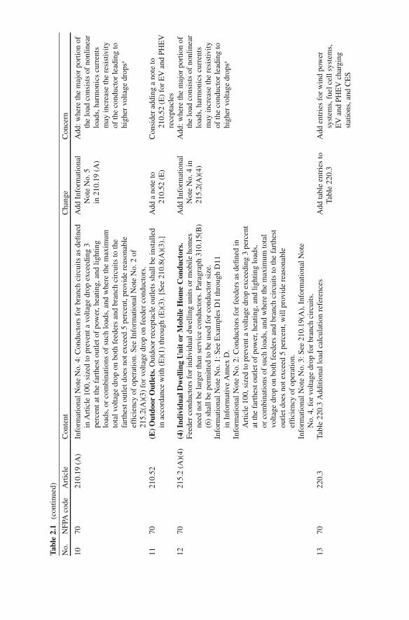
No.
N
FPA
cod
e A
rtic
le
Con
tent
C
hang
e C
once
rn
10
70
210.
19 (
A)
Info
rmat
iona
l Not
e N
o. 4
: Con
duct
ors
for
bran
ch c
ircu
its a
s de
fi ned
in
Art
icle
100
, siz
ed to
pre
vent
a v
olta
ge d
rop
exce
edin
g 3
perc
ent a
t the
far
thes
t out
let o
f po
wer
, hea
ting,
and
ligh
ting
load
s, o
r co
mbi
natio
ns o
f su
ch lo
ads,
and
whe
re th
e m
axim
um
tota
l vol
tage
dro
p on
bot
h fe
eder
s an
d br
anch
cir
cuits
to th
e fa
rthe
st o
utle
t doe
s no
t exc
eed
5 pe
rcen
t, pr
ovid
e re
ason
able
ef
fi cie
ncy
of o
pera
tion.
See
Inf
orm
atio
nal N
ote
No.
2 o
f 21
5.2(
A)(
3) f
or v
olta
ge d
rop
on f
eede
r co
nduc
tors
.
Add
Inf
orm
atio
nal
Not
e N
o. 5
in
210
.19
(A)
Add
: whe
re th
e m
ajor
por
tion
of
the
load
con
sist
s of
non
linea
r lo
ads,
har
mon
ics
curr
ents
m
ay in
crea
se th
e re
sist
ivity
of
the
cond
ucto
r le
adin
g to
hi
gher
vol
tage
dro
ps a
11
70
210.
52
(E)
Out
door
Out
lets
. Out
door
rec
epta
cle
outle
ts s
hall
be in
stal
led
in a
ccor
danc
e w
ith (
E)(
1) th
roug
h (E
)(3)
. [Se
e 21
0.8(
A)(
3).]
A
dd a
not
e to
21
0.52
(E
) C
onsi
der
addi
ng a
not
e to
21
0.52
(E
) fo
r E
V a
nd P
HE
V
rece
ptac
les
12
70
215.
2 (A
)(4)
(4
) In
divi
dual
Dw
ellin
g U
nit
or M
obile
Hom
e C
ondu
ctor
s.
Add
Inf
orm
atio
nal
Not
e N
o. 4
in
215.
2(A
)(4)
Add
: whe
re th
e m
ajor
por
tion
of
the
load
con
sist
s of
non
linea
r lo
ads,
har
mon
ics
curr
ents
m
ay in
crea
se th
e re
sist
ivity
of
the
cond
ucto
r le
adin
g to
hi
gher
vol
tage
dro
ps a
Feed
er c
ondu
ctor
s fo
r in
divi
dual
dw
ellin
g un
its o
r m
obile
hom
es
need
not
be
larg
er th
an s
ervi
ce c
ondu
ctor
s. P
arag
raph
310
.15(
B)
(6)
shal
l be
perm
itted
to b
e us
ed f
or c
ondu
ctor
siz
e.
Info
rmat
iona
l Not
e N
o. 1
: See
Exa
mpl
es D
1 th
roug
h D
11
in I
nfor
mat
ive
Ann
ex D
. In
form
atio
nal N
ote
No.
2: C
ondu
ctor
s fo
r fe
eder
s as
de fi
ned
in
Art
icle
100
, siz
ed to
pre
vent
a v
olta
ge d
rop
exce
edin
g 3
perc
ent
at th
e fa
rthe
st o
utle
t of
pow
er, h
eatin
g, a
nd li
ghtin
g lo
ads,
or
com
bina
tions
of
such
load
s, a
nd w
here
the
max
imum
tota
l vo
ltage
dro
p on
bot
h fe
eder
s an
d br
anch
cir
cuits
to th
e fa
rthe
st
outle
t doe
s no
t exc
eed
5 pe
rcen
t, w
ill p
rovi
de r
easo
nabl
e ef
fi cie
ncy
of o
pera
tion.
In
form
atio
nal N
ote
No.
3: S
ee 2
10.1
9(A
), I
nfor
mat
iona
l Not
e N
o. 4
, for
vol
tage
dro
p fo
r br
anch
cir
cuits
. 13
70
22
0.3
Tabl
e 22
0.3
Add
ition
al lo
ad c
alcu
latio
n re
fere
nces
A
dd ta
ble
entr
ies
to
Tabl
e 22
0.3
Add
ent
ries
for
win
d po
wer
sy
stem
s, f
uel c
ell s
yste
ms,
E
V a
nd P
HE
V c
harg
ing
stat
ions
, and
CE
S
Tabl
e 2.
1 (c
ontin
ued)

No.
N
FPA
cod
e A
rtic
le
Con
tent
C
hang
e C
once
rn
14
70
220.
14
(L)
Oth
er O
utle
ts. O
ther
out
lets
not
cov
ered
in 2
20.1
4(A
) th
roug
h (K
) sh
all b
e ca
lcul
ated
bas
ed o
n 18
0 vo
lt-am
pere
s pe
r ou
tlet.
Add
220
.14
(M)
Add
: 220
.14
(M)
EV
and
PH
EV
re
cept
acle
s ou
tlets
. An
outle
t fo
r E
V a
nd P
HE
V s
hall
be
calc
ulat
ed b
ased
on
the
ampe
re r
atin
g of
the
EV
and
PH
EV
equ
ipm
ent s
erve
d 15
70
22
0.44
Ta
ble
220.
44
Add
tabl
e en
trie
s to
Ta
ble
220.
44
Con
side
r ad
ding
com
mer
cial
EV
an
d PH
EV
cha
rgin
g st
atio
ns
and
CE
S to
Tab
le 2
20.4
4 16
70
23
0.82
(6
) So
lar
phot
ovol
taic
sys
tem
s, f
uel c
ell s
yste
ms,
or
inte
rcon
nect
ed
elec
tric
pow
er p
rodu
ctio
n so
urce
s.
Add
to 2
30.8
2 (6
) A
dd w
ind
pow
er s
yste
ms
to
230.
82 (
6)
17
70
240.
3 Ta
ble
240.
3 ot
her
artic
les
Add
tabl
e en
trie
s to
Ta
ble
240.
3 A
dd e
ntri
es f
or w
ind
pow
er
syst
ems,
fue
l cel
l sys
tem
s,
EV
and
PH
EV
cha
rgin
g st
atio
ns, a
nd C
ES
18
70
250.
3 Ta
ble
250.
3 A
dditi
onal
gro
undi
ng a
nd b
ondi
ng r
equi
rem
ents
A
dd ta
ble
entr
ies
to
Tabl
e 25
0.3
Add
ent
ries
for
win
d po
wer
sy
stem
s, f
uel c
ell s
yste
ms,
E
V a
nd P
HE
V c
harg
ing
stat
ions
, and
CE
S 19
70
42
2.31
(A
) R
ated
at
Not
ove
r 30
0 V
olt-
Am
pere
s or
1⁄8
Hor
sepo
wer
. For
pe
rman
ently
con
nect
ed a
pplia
nces
rat
ed a
t not
ove
r 30
0 vo
lt-am
pere
s or
1⁄8
hp,
the
bran
ch-c
ircu
it ov
ercu
rren
t dev
ice
shal
l be
perm
itted
to s
erve
as
the
disc
onne
ctin
g m
eans
. (B
) A
pplia
nces
Rat
ed o
ver
300
Vol
t-A
mpe
res.
For
per
man
ently
co
nnec
ted
appl
ianc
es r
ated
ove
r 30
0 vo
ltam
pere
s, th
e br
anch
-ci
rcui
t sw
itch
or c
ircu
it br
eake
r sh
all b
e pe
rmitt
ed to
ser
ve a
s th
e di
scon
nect
ing
mea
ns w
here
the
switc
h or
cir
cuit
brea
ker
is w
ithin
sig
ht f
rom
the
appl
ianc
e or
is c
apab
le o
f be
ing
lock
ed
in th
e op
en p
ositi
on. T
he p
rovi
sion
for
lock
ing
or a
ddin
g a
lock
to
the
disc
onne
ctin
g m
eans
sha
ll be
inst
alle
d on
or
at th
e sw
itch
or c
ircu
it br
eake
r us
ed a
s th
e di
scon
nect
ing
mea
ns a
nd s
hall
rem
ain
in p
lace
with
or
with
out t
he lo
ck in
stal
led.
Aug
men
t 422
.31
(A) ,
(B
), an
d (C
) A
ugm
ent 4
22.3
1 (A
) , (
B),
and
(C
) to
incl
ude
capa
bilit
y to
co
mm
unic
ate
with
sm
art
met
er a
nd E
MS
to b
oth
sens
e po
wer
sta
tus
and
rem
otel
y co
ntro
l/dis
conn
ect a
pplia
nce
(con
tinue
d)
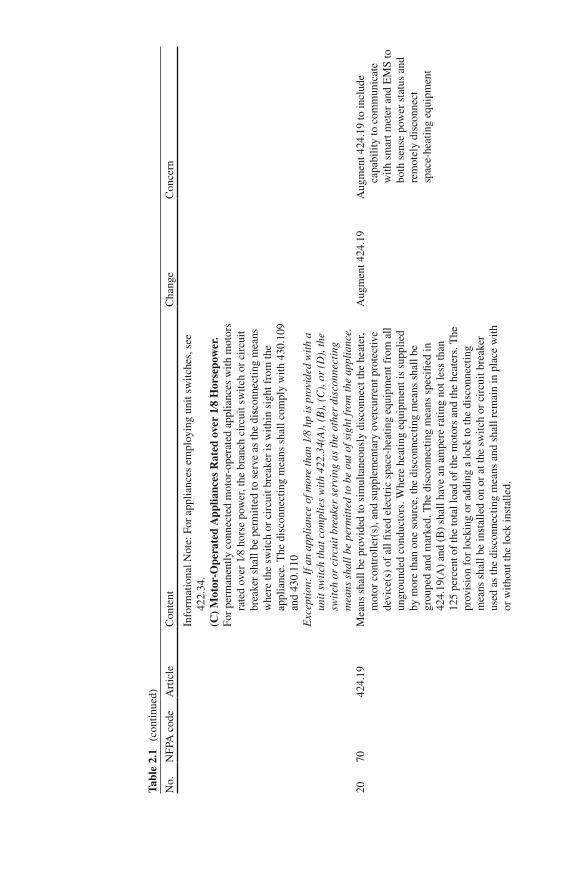
No.
N
FPA
cod
e A
rtic
le
Con
tent
C
hang
e C
once
rn
Info
rmat
iona
l Not
e: F
or a
pplia
nces
em
ploy
ing
unit
switc
hes,
see
42
2.34
. (C
) M
otor
-Ope
rate
d A
pplia
nces
Rat
ed o
ver
1⁄8
Hor
sepo
wer
. Fo
r pe
rman
ently
con
nect
ed m
otor
-ope
rate
d ap
plia
nces
with
mot
ors
rate
d ov
er 1
⁄8 h
orse
pow
er, t
he b
ranc
h ci
rcui
t sw
itch
or c
ircu
it br
eake
r sh
all b
e pe
rmitt
ed to
ser
ve a
s th
e di
scon
nect
ing
mea
ns
whe
re th
e sw
itch
or c
ircu
it br
eake
r is
with
in s
ight
fro
m th
e ap
plia
nce.
The
dis
conn
ectin
g m
eans
sha
ll co
mpl
y w
ith 4
30.1
09
and
430.
110
Exc
epti
on:
If a
n ap
plia
nce
of m
ore
than
1⁄8
hp
is p
rovi
ded
wit
h a
unit
sw
itch
that
com
plie
s w
ith
422.
34(A
), (
B),
(C
), o
r (D
), th
e sw
itch
or
circ
uit b
reak
er s
ervi
ng a
s th
e ot
her
disc
onne
ctin
g m
eans
sha
ll b
e pe
rmit
ted
to b
e ou
t of s
ight
from
the
appl
ianc
e.
20
70
424.
19
Mea
ns s
hall
be p
rovi
ded
to s
imul
tane
ousl
y di
scon
nect
the
heat
er,
mot
or c
ontr
olle
r(s)
, and
sup
plem
enta
ry o
verc
urre
nt p
rote
ctiv
e de
vice
(s)
of a
ll fi x
ed e
lect
ric
spac
e-he
atin
g eq
uipm
ent f
rom
all
ungr
ound
ed c
ondu
ctor
s. W
here
hea
ting
equi
pmen
t is
supp
lied
by m
ore
than
one
sou
rce,
the
disc
onne
ctin
g m
eans
sha
ll be
gr
oupe
d an
d m
arke
d. T
he d
isco
nnec
ting
mea
ns s
peci
fi ed
in
424.
19(A
) an
d (B
) sh
all h
ave
an a
mpe
re r
atin
g no
t les
s th
an
125
perc
ent o
f th
e to
tal l
oad
of th
e m
otor
s an
d th
e he
ater
s. T
he
prov
isio
n fo
r lo
ckin
g or
add
ing
a lo
ck to
the
disc
onne
ctin
g m
eans
sha
ll be
inst
alle
d on
or
at th
e sw
itch
or c
ircu
it br
eake
r us
ed a
s th
e di
scon
nect
ing
mea
ns a
nd s
hall
rem
ain
in p
lace
with
or
with
out t
he lo
ck in
stal
led.
Aug
men
t 424
.19
Aug
men
t 424
.19
to in
clud
e ca
pabi
lity
to c
omm
unic
ate
with
sm
art m
eter
and
EM
S to
bo
th s
ense
pow
er s
tatu
s an
d re
mot
ely
disc
onne
ct
spac
e-he
atin
g eq
uipm
ent
Tabl
e 2.
1 (c
ontin
ued)
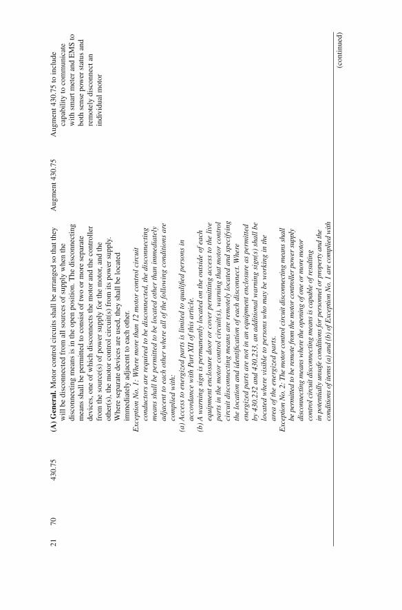
No.
N
FPA
cod
e A
rtic
le
Con
tent
C
hang
e C
once
rn
21
70
430.
75
(A)
Gen
eral
. Mot
or c
ontr
ol c
ircu
its s
hall
be a
rran
ged
so th
at th
ey
will
be
disc
onne
cted
fro
m a
ll so
urce
s of
sup
ply
whe
n th
e di
scon
nect
ing
mea
ns is
in th
e op
en p
ositi
on. T
he d
isco
nnec
ting
mea
ns s
hall
be p
erm
itted
to c
onsi
st o
f tw
o or
mor
e se
para
te
devi
ces,
one
of
whi
ch d
isco
nnec
ts th
e m
otor
and
the
cont
rolle
r fr
om th
e so
urce
(s)
of p
ower
sup
ply
for
the
mot
or, a
nd th
e ot
her(
s), t
he m
otor
con
trol
cir
cuit(
s) f
rom
its
pow
er s
uppl
y.
Whe
re s
epar
ate
devi
ces
are
used
, the
y sh
all b
e lo
cate
d im
med
iate
ly a
djac
ent t
o ea
ch o
ther
.
Aug
men
t 430
.75
Aug
men
t 430
.75
to in
clud
e ca
pabi
lity
to c
omm
unic
ate
with
sm
art m
eter
and
EM
S to
bo
th s
ense
pow
er s
tatu
s an
d re
mot
ely
disc
onne
ct a
n in
divi
dual
mot
or
Exc
epti
on N
o. 1
: W
here
mor
e th
an 1
2 m
otor
con
trol
cir
cuit
co
nduc
tors
are
req
uire
d to
be
disc
onne
cted
, the
dis
conn
ecti
ng
mea
ns s
hall
be
perm
itte
d to
be
loca
ted
othe
r th
an im
med
iate
ly
adja
cent
to e
ach
othe
r w
here
all
of t
he fo
llow
ing
cond
itio
ns a
re
com
plie
d w
ith:
(a
) A
cces
s to
ene
rgiz
ed p
arts
is li
mit
ed to
qua
li fi e
d pe
rson
s in
ac
cord
ance
wit
h Pa
rt X
II o
f thi
s ar
ticl
e.
(b)
A w
arni
ng s
ign
is p
erm
anen
tly
loca
ted
on th
e ou
tsid
e of
eac
h eq
uipm
ent e
nclo
sure
doo
r or
cov
er p
erm
itti
ng a
cces
s to
the
live
pa
rts
in th
e m
otor
con
trol
cir
cuit
(s),
war
ning
that
mot
or c
ontr
ol
circ
uit d
isco
nnec
ting
mea
ns a
re r
emot
ely
loca
ted
and
spec
ifyi
ng
the
loca
tion
and
iden
ti fi c
atio
n of
eac
h di
scon
nect
. Whe
re
ener
gize
d pa
rts
are
not i
n an
equ
ipm
ent e
nclo
sure
as
perm
itte
d by
430
.232
and
430
.233
, an
addi
tion
al w
arni
ng s
ign(
s) s
hall
be
loca
ted
whe
re v
isib
le to
per
sons
who
may
be
wor
king
in th
e ar
ea o
f the
ene
rgiz
ed p
arts
. E
xcep
tion
No.
2: T
he m
otor
con
trol
cir
cuit
disc
onne
ctin
g m
eans
sha
ll be
per
mitt
ed to
be
rem
ote
from
the
mot
or c
ontr
olle
r po
wer
sup
ply
disc
onne
ctin
g m
eans
whe
re th
e op
enin
g of
one
or
mor
e m
otor
co
ntro
l cir
cuit
disc
onne
ctin
g m
eans
is c
apab
le o
f res
ultin
g in
pot
entia
lly u
nsaf
e co
nditi
ons
for
pers
onne
l or
prop
erty
and
the
cond
ition
s of
item
s (a
) and
(b) o
f Exc
eptio
n N
o. 1
are
com
plie
d w
ith
(con
tinue
d)
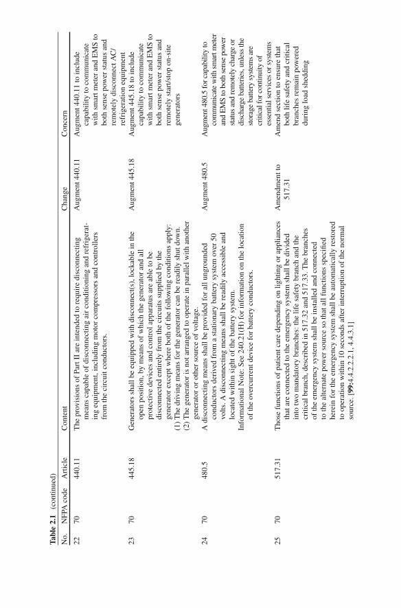
No.
N
FPA
cod
e A
rtic
le
Con
tent
C
hang
e C
once
rn
22
70
440.
11
The
pro
visi
ons
of P
art I
I ar
e in
tend
ed to
req
uire
dis
conn
ectin
g m
eans
cap
able
of
disc
onne
ctin
g ai
r co
nditi
onin
g an
d re
frig
erat
-in
g eq
uipm
ent,
incl
udin
g m
otor
com
pres
sors
and
con
trol
lers
fr
om th
e ci
rcui
t con
duct
ors.
Aug
men
t 440
.11
Aug
men
t 440
.11
to in
clud
e ca
pabi
lity
to c
omm
unic
ate
with
sm
art m
eter
and
EM
S to
bo
th s
ense
pow
er s
tatu
s an
d re
mot
ely
disc
onne
ct A
C/
refr
iger
atio
n eq
uipm
ent
23
70
445.
18
Gen
erat
ors
shal
l be
equi
pped
with
dis
conn
ect(
s), l
ocka
ble
in th
e op
en p
ositi
on, b
y m
eans
of
whi
ch th
e ge
nera
tor
and
all
prot
ectiv
e de
vice
s an
d co
ntro
l app
arat
us a
re a
ble
to b
e di
scon
nect
ed e
ntir
ely
from
the
circ
uits
sup
plie
d by
the
gene
rato
r ex
cept
whe
re b
oth
of th
e fo
llow
ing
cond
ition
s ap
ply:
(1
) T
he d
rivi
ng m
eans
for
the
gene
rato
r ca
n be
rea
dily
shu
t dow
n.
(2)
The
gen
erat
or is
not
arr
ange
d to
ope
rate
in p
aral
lel w
ith a
noth
er
gene
rato
r or
oth
er s
ourc
e of
vol
tage
.
Aug
men
t 445
.18
Aug
men
t 445
.18
to in
clud
e ca
pabi
lity
to c
omm
unic
ate
with
sm
art m
eter
and
EM
S to
bo
th s
ense
pow
er s
tatu
s an
d re
mot
ely
star
t/sto
p on
-site
ge
nera
tors
24
70
480.
5 A
dis
conn
ectin
g m
eans
sha
ll be
pro
vide
d fo
r al
l ung
roun
ded
cond
ucto
rs d
eriv
ed f
rom
a s
tatio
nary
bat
tery
sys
tem
ove
r 50
vo
lts. A
dis
conn
ectin
g m
eans
sha
ll be
rea
dily
acc
essi
ble
and
loca
ted
with
in s
ight
of
the
batte
ry s
yste
m.
Info
rmat
iona
l Not
e: S
ee 2
40.2
1(H
) fo
r in
form
atio
n on
the
loca
tion
of th
e ov
ercu
rren
t dev
ice
for
batte
ry c
ondu
ctor
s.
Aug
men
t 480
.5
Aug
men
t 480
.5 fo
r cap
abili
ty to
co
mm
unic
ate
with
sm
art m
eter
an
d E
MS
to b
oth
sens
e po
wer
st
atus
and
rem
otel
y ch
arge
or
disc
harg
e ba
tteri
es, u
nles
s th
e st
orag
e ba
ttery
sys
tem
s ar
e cr
itica
l for
con
tinui
ty o
f es
sent
ial s
ervi
ces
or s
yste
ms
25
70
517.
31
Tho
se f
unct
ions
of
patie
nt c
are
depe
ndin
g on
ligh
ting
or a
pplia
nces
th
at a
re c
onne
cted
to th
e em
erge
ncy
syst
em s
hall
be d
ivid
ed
into
two
man
dato
ry b
ranc
hes:
the
life
safe
ty b
ranc
h an
d th
e cr
itica
l bra
nch,
des
crib
ed in
517
.32
and
517.
33. T
he b
ranc
hes
of th
e em
erge
ncy
syst
em s
hall
be in
stal
led
and
conn
ecte
d to
the
alte
rnat
e po
wer
sou
rce
so th
at a
ll fu
nctio
ns s
peci
fi ed
here
in f
or th
e em
erge
ncy
syst
em s
hall
be a
utom
atic
ally
res
tore
d to
ope
ratio
n w
ithin
10
seco
nds
afte
r in
terr
uptio
n of
the
norm
al
sour
ce. [
99: 4
.4.2
.2.2
.1, 4
.4.3
.1]
Am
endm
ent t
o 51
7.31
A
men
d se
ctio
n to
ens
ure
that
bo
th li
fe s
afet
y an
d cr
itica
l br
anch
es r
emai
n po
wer
ed
duri
ng lo
ad s
hedd
ing
Tabl
e 2.
1 (c
ontin
ued)

No.
N
FPA
cod
e A
rtic
le
Con
tent
C
hang
e C
once
rn
26
70
625.
26
Ele
ctri
c ve
hicl
e su
pply
equ
ipm
ent a
nd o
ther
par
ts o
f a
syst
em,
eith
er o
n-bo
ard
or o
ff-b
oard
the
vehi
cle,
that
are
iden
ti fi ed
fo
r an
d in
tend
ed to
be
inte
rcon
nect
ed to
a v
ehic
le a
nd a
lso
serv
e as
an
optio
nal s
tand
by s
yste
m o
r an
ele
ctri
c po
wer
pro
duct
ion
sour
ce o
r pr
ovid
e fo
r bi
-dir
ectio
nal p
ower
fee
d sh
all b
e lis
ted
as s
uita
ble
for
that
pur
pose
. Whe
n us
ed a
s an
opt
iona
l sta
ndby
sy
stem
, the
req
uire
men
ts o
f A
rtic
le 7
02 s
hall
appl
y, a
nd w
hen
used
as
an e
lect
ric
pow
er p
rodu
ctio
n so
urce
, the
req
uire
men
ts
of A
rtic
le 7
05 s
hall
appl
y.
Add
Inf
orm
atio
n N
ote
No.
1
Add
Inf
orm
atio
n N
ote
#1 th
at
expa
nds
upon
the
role
of
EV
s an
d PH
EV
s to
com
mun
icat
e w
ith a
sm
art m
eter
and
EM
S to
bot
h se
nse
pow
er s
tatu
s an
d re
mot
ely
enab
le th
e E
V/
PHE
V to
be
an e
lect
ric
pow
er p
rodu
ctio
n so
urce
27
70
700.
4 (A
) C
apac
ity
and
Rat
ing.
An
emer
genc
y sy
stem
sha
ll ha
ve
adeq
uate
cap
acity
and
rat
ing
for
all l
oads
to b
e op
erat
ed
sim
ulta
neou
sly.
The
em
erge
ncy
syst
em e
quip
men
t sha
ll be
sui
tabl
e fo
r the
max
imum
ava
ilabl
e fa
ult c
urre
nt a
t its
term
inal
s.
Am
end
700.
4 A
men
d 70
0.4
(B)
to in
clud
e sa
fegu
ards
, suc
h as
a
diff
eren
t EM
S, a
gain
st th
e em
erge
ncy
syst
em b
eing
tr
eate
d as
a r
egul
ar s
yste
m
for
the
purp
oses
of
load
sh
eddi
ng b
(B)
Sele
ctiv
e L
oad
Pic
kup,
Loa
d Sh
eddi
ng, a
nd P
eak
Loa
d Sh
avin
g. T
he a
ltern
ate
pow
er s
ourc
e sh
all b
e pe
rmitt
ed
to s
uppl
y em
erge
ncy,
lega
lly r
equi
red
stan
dby,
and
opt
iona
l st
andb
y sy
stem
load
s w
here
the
sour
ce h
as a
dequ
ate
capa
city
or
whe
re a
utom
atic
sel
ectiv
e lo
ad p
icku
p an
d lo
ad s
hedd
ing
is p
rovi
ded
as n
eede
d to
ens
ure
adeq
uate
pow
er to
(1)
the
emer
genc
y ci
rcui
ts, (
2) th
e le
gally
req
uire
d st
andb
y ci
rcui
ts,
and
(3)
the
optio
nal s
tand
by c
ircu
its, i
n th
at o
rder
of
prio
rity
. T
he a
ltern
ate
pow
er s
ourc
e sh
all b
e pe
rmitt
ed to
be
used
fo
r pe
ak lo
ad s
havi
ng, p
rovi
ded
thes
e co
nditi
ons
are
met
. Pe
ak lo
ad s
havi
ng o
pera
tion
shal
l be
perm
itted
for
sat
isfy
ing
the
test
req
uire
men
t of
700.
3(B
), p
rovi
ded
all o
ther
con
ditio
ns
of 7
00.3
are
met
.
(con
tinue
d)

No.
N
FPA
cod
e A
rtic
le
Con
tent
C
hang
e C
once
rn
28
70
701.
4 A
lega
lly r
equi
red
stan
dby
syst
em s
hall
have
ade
quat
e ca
paci
ty a
nd
ratin
g fo
r th
e su
pply
of
all e
quip
men
t int
ende
d to
be
oper
ated
at
one
time.
Leg
ally
req
uire
d st
andb
y sy
stem
equ
ipm
ent s
hall
be
suita
ble
for
the
max
imum
ava
ilabl
e fa
ult c
urre
nt a
t its
term
inal
s.
Am
end
701.
4 A
men
d 70
1.4
to c
lari
fy if
the
stan
dby
syst
em m
ay b
e us
ed
for
othe
r pu
rpos
es, s
uch
as
peak
load
sha
ving
, sim
ilar
to
700.
5 (B
). A
ltern
ativ
ely,
re
fere
nce
the
artic
le, s
uch
as
705,
und
er w
hich
thes
e is
sues
are
add
ress
ed. I
f ot
her
uses
are
allo
wed
, the
re
com
men
datio
n is
als
o to
in
clud
e sa
fegu
ards
, suc
h as
a
diff
eren
t EM
S, a
gain
st th
e em
erge
ncy
syst
em b
eing
tr
eate
d as
a r
egul
ar s
yste
m
for
the
purp
oses
of
load
sh
eddi
ng b
The
lega
lly r
equi
red
stan
dby
alte
rnat
e po
wer
sou
rce
shal
l be
perm
itted
to s
uppl
y bo
th le
gally
req
uire
d st
andb
y an
d op
tiona
l st
andb
y sy
stem
load
s un
der
eith
er o
f th
e fo
llow
ing
cond
ition
s:
(1)
Whe
re th
e al
tern
ate
sour
ce h
as a
dequ
ate
capa
city
to h
andl
e al
l co
nnec
ted
load
s (2
) W
here
aut
omat
ic s
elec
tive
load
pic
kup
and
load
she
ddin
g is
pro
vide
d th
at w
ill e
nsur
e ad
equa
te p
ower
to th
e le
gally
re
quir
ed s
tand
by c
ircu
its.
29
70
705
Art
icle
705
inte
rcon
nect
ed e
lect
rica
l pow
er p
rodu
ctio
n sy
stem
s A
dd a
sub
sect
ion
Add
a s
ubse
ctio
n to
art
icle
705
to
add
ress
sm
art g
rid
switc
hing
cap
abili
ties b
30
70
705
Tabl
e 70
5.3
othe
r ar
ticle
s A
dd it
ems
to T
able
70
5.3
amen
d Ta
ble
705.
3 to
incl
ude
othe
r em
ergi
ng p
rodu
ctio
n so
urce
s su
ch a
s w
ind
gene
ratio
n 31
70
70
5.20
M
eans
sha
ll be
pro
vide
d to
dis
conn
ect a
ll un
grou
nded
con
duct
ors
of a
n el
ectr
ic p
ower
pro
duct
ion
sour
ce(s
) fr
om a
ll ot
her
cond
ucto
rs.
Am
end
705.
20
Am
end
705.
20 o
r ad
d an
art
icle
to
incl
ude
a lo
ck-o
ut-t
ag-o
ut
syst
em f
or E
MS
or o
ther
sm
art g
rid
tech
nolo
gy
cont
rolle
d ge
nera
tion
syst
ems b
Tabl
e 2.
1 (c
ontin
ued)

No.
N
FPA
cod
e A
rtic
le
Con
tent
C
hang
e C
once
rn
32
70
705.
30
Con
duct
ors
shal
l be
prot
ecte
d in
acc
orda
nce
with
Art
icle
240
. E
quip
men
t and
con
duct
ors
conn
ecte
d to
mor
e th
an o
ne
elec
tric
al s
ourc
e sh
all h
ave
a su
f fi ci
ent n
umbe
r of
ove
rcur
rent
de
vice
s lo
cate
d so
as
to p
rovi
de p
rote
ctio
n fr
om a
ll so
urce
s.
Add
item
s to
705
.30
Add
add
ition
al le
tter
item
s, (
F),
(G),
etc
., to
incl
ude
othe
r em
ergi
ng p
rodu
ctio
n so
urce
s su
ch a
s w
ind
gene
ratio
n (A
) So
lar
Pho
tovo
ltai
c Sy
stem
s. S
olar
pho
tovo
ltaic
sys
tem
s sh
all
be p
rote
cted
in a
ccor
danc
e w
ith A
rtic
le 6
90.
(B)
Tra
nsfo
rmer
s. O
verc
urre
nt p
rote
ctio
n fo
r a
tran
sfor
mer
with
a
sour
ce(s
) on
eac
h si
de s
hall
be p
rovi
ded
in a
ccor
danc
e w
ith
450.
3 by
con
side
ring
fi rs
t one
sid
e of
the
tran
sfor
mer
, the
n th
e ot
her
side
of
the
tran
sfor
mer
, as
the
prim
ary.
(C
) F
uel C
ell S
yste
ms.
Fue
l cel
l sys
tem
s sh
all b
e pr
otec
ted
in
acco
rdan
ce w
ith A
rtic
le 6
92.
(D)
Uti
lity-
Inte
ract
ive
Inve
rter
s. U
tility
-int
erac
tive
inve
rter
s sh
all
be p
rote
cted
in a
ccor
danc
e w
ith 7
05.6
5.
(E)
Gen
erat
ors.
Gen
erat
ors
shal
l be
prot
ecte
d in
acc
orda
nce
with
70
5.13
0.
33
70
705.
40
Upo
n lo
ss o
f pr
imar
y so
urce
, an
elec
tric
pow
er p
rodu
ctio
n so
urce
sh
all b
e au
tom
atic
ally
dis
conn
ecte
d fr
om a
ll un
grou
nded
co
nduc
tors
of
the
prim
ary
sour
ce a
nd s
hall
not b
e re
conn
ecte
d un
til th
e pr
imar
y so
urce
is r
esto
red.
E
xcep
tion
: A
list
ed u
tili
ty-i
nter
acti
ve in
vert
er s
hall
be
perm
itte
d to
aut
omat
ical
ly c
ease
exp
orti
ng p
ower
upo
n lo
ss o
f pri
mar
y so
urce
and
sha
ll n
ot b
e re
quir
ed to
aut
omat
ical
ly d
isco
nnec
t all
un
grou
nded
con
duct
ors
from
the
prim
ary
sour
ce. A
list
ed
util
ity-
inte
ract
ive
inve
rter
sha
ll b
e pe
rmit
ted
to a
utom
atic
ally
or
man
uall
y re
sum
e ex
port
ing
pow
er to
the
util
ity
once
the
prim
ary
sour
ce is
res
tore
d
Am
end
705.
40
Am
end
705.
40 to
add
sce
nari
os
as a
ppro
pria
te to
incl
ude
actio
ns th
at s
houl
d be
take
n by
an
EM
S or
oth
er s
mar
t gr
id s
witc
hing
sys
tem
in th
e ev
ent o
f pr
imar
y po
wer
loss
(con
tinue
d)

No.
N
FPA
cod
e A
rtic
le
Con
tent
C
hang
e C
once
rn
Info
rmat
iona
l Not
e N
o. 1
: Ris
ks to
per
sonn
el a
nd e
quip
men
t as
soci
ated
with
the
prim
ary
sour
ce c
ould
occ
ur if
an
utili
ty
inte
ract
ive
elec
tric
pow
er p
rodu
ctio
n so
urce
can
ope
rate
as
an
inte
ntio
nal i
slan
d. S
peci
al d
etec
tion
met
hods
are
req
uire
d to
det
erm
ine
that
a p
rim
ary
sour
ce s
uppl
y sy
stem
out
age
has
occu
rred
and
whe
ther
ther
e sh
ould
be
auto
mat
ic d
isco
nnec
tion.
W
hen
the
prim
ary
sour
ce s
uppl
y sy
stem
is r
esto
red,
spe
cial
de
tect
ion
met
hods
can
be
requ
ired
to li
mit
expo
sure
of
pow
er
prod
uctio
n so
urce
s to
out
-of-
phas
e re
conn
ectio
n.
Info
rmat
iona
l Not
e N
o. 2
: Ind
uctio
n-ge
nera
ting
equi
pmen
t on
syst
ems
with
sig
ni fi c
ant c
apac
itanc
e ca
n be
com
e se
lf-e
xcite
d up
on lo
ss o
f th
e pr
imar
y so
urce
and
exp
erie
nce
seve
re
over
volta
ge a
s a
resu
lt.
A u
tility
-int
erac
tive
inve
rter
sha
ll be
per
mitt
ed to
ope
rate
as
a st
and-
alon
e sy
stem
to s
uppl
y lo
ads
that
hav
e be
en d
isco
nnec
ted
from
ele
ctri
cal p
rodu
ctio
n an
d di
stri
butio
n ne
twor
k so
urce
s.
34
70
708.
22
“ (A
) C
apac
ity
and
Rat
ing.
A C
OPS
sha
ll ha
ve c
apac
ity a
nd r
atin
g fo
r al
l loa
ds to
be
oper
ated
sim
ulta
neou
sly
for
cont
inuo
us
oper
atio
n w
ith v
aria
ble
load
for
an
unlim
ited
num
ber
of h
ours
, ex
cept
for
req
uire
d m
aint
enan
ce o
f th
e po
wer
sou
rce.
A
port
able
, tem
pora
ry, o
r re
dund
ant a
ltern
ate
pow
er s
ourc
e sh
all
be a
vaila
ble
for
use
whe
neve
r th
e C
OPS
pow
er s
ourc
e is
out
of
ser
vice
for
mai
nten
ance
or
repa
ir.”
Am
end
708.
22 (
B)
Am
end
708.
22 (
B)
to in
clud
e sa
fegu
ards
, suc
h as
a
diff
eren
t EM
S, a
gain
st th
e em
erge
ncy
syst
em b
eing
tr
eate
d as
a r
egul
ar s
yste
m
for
the
purp
oses
of
load
sh
eddi
ng
(B)
Sele
ctiv
e L
oad
Pic
kup,
Loa
d Sh
eddi
ng, a
nd P
eak
Loa
d Sh
avin
g. T
he a
ltern
ate
pow
er s
ourc
e sh
all b
e pe
rmitt
ed to
su
pply
CO
PS e
mer
genc
y, le
gally
req
uire
d st
andb
y, a
nd o
ptio
nal
load
s w
here
the
sour
ce h
as a
dequ
ate
capa
city
or
whe
re
auto
mat
ic s
elec
tive
load
pic
kup
and
load
she
ddin
g is
pro
vide
d as
nee
ded
to e
nsur
e ad
equa
te p
ower
to (
1) th
e C
OPS
and
em
erge
ncy
circ
uits
, (2)
the
lega
lly r
equi
red
stan
dby
circ
uits
, an
d (3
) th
e op
tiona
l sta
ndby
cir
cuits
, in
that
ord
er o
f pr
iori
ty.
The
alte
rnat
e po
wer
sou
rce
shal
l be
perm
itted
to b
e us
ed f
or
peak
load
sha
ving
, pro
vide
d th
ese
cond
ition
s ar
e m
et.
Tabl
e 2.
1 (c
ontin
ued)
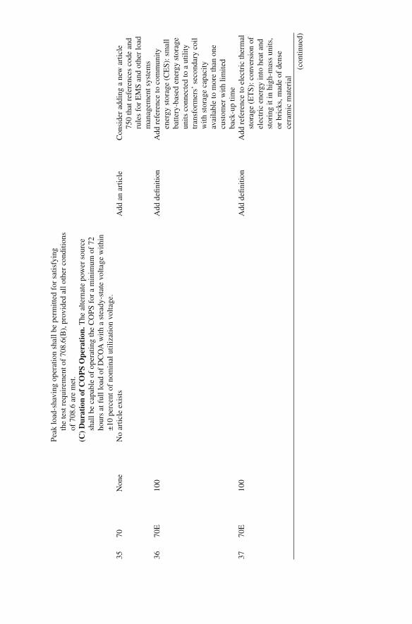
No.
N
FPA
cod
e A
rtic
le
Con
tent
C
hang
e C
once
rn
Peak
load
-sha
ving
ope
ratio
n sh
all b
e pe
rmitt
ed f
or s
atis
fyin
g th
e te
st r
equi
rem
ent o
f 70
8.6(
B),
pro
vide
d al
l oth
er c
ondi
tions
of
708
.6 a
re m
et.
(C)
Dur
atio
n of
CO
PS
Ope
rati
on. T
he a
ltern
ate
pow
er s
ourc
e sh
all b
e ca
pabl
e of
ope
ratin
g th
e C
OPS
for
a m
inim
um o
f 72
ho
urs
at f
ull l
oad
of D
CO
A w
ith a
ste
ady-
stat
e vo
ltage
with
in
±10
per
cent
of
nom
inal
util
izat
ion
volta
ge.
35
70
Non
e N
o ar
ticle
exi
sts
Add
an
artic
le
Con
side
r ad
ding
a n
ew a
rtic
le
750
that
ref
eren
ces
code
and
ru
les
for
EM
S an
d ot
her
load
m
anag
emen
t sys
tem
s 36
70
E
100
Add
de fi
nitio
n A
dd r
efer
ence
to c
omm
unity
en
ergy
sto
rage
(C
ES)
: sm
all
batte
ry-b
ased
ene
rgy
stor
age
units
con
nect
ed to
a u
tility
tr
ansf
orm
ers’
sec
onda
ry c
oil
with
sto
rage
cap
acity
av
aila
ble
to m
ore
than
one
cu
stom
er w
ith li
mite
d ba
ck-u
p tim
e 37
70
E
100
Add
de fi
nitio
n A
dd r
efer
ence
to e
lect
ric
ther
mal
st
orag
e (E
TS)
: con
vers
ion
of
elec
tric
ene
rgy
into
hea
t and
st
orin
g it
in h
igh-
mas
s un
its,
or b
rick
s, m
ade
of d
ense
ce
ram
ic m
ater
ial
(con
tinue
d)

No.
N
FPA
cod
e A
rtic
le
Con
tent
C
hang
e C
once
rn
38
70E
10
0 A
dd d
e fi ni
tion
Add
ref
eren
ce to
ene
rgy
mon
itori
ng a
nd c
ontr
ol
syst
em (
EM
CS)
, ene
rgy
man
agem
ent s
yste
m (
EM
S),
ener
gy in
form
atio
n sy
stem
(E
IS):
sys
tem
s w
hich
mon
itor
ener
gy c
onsu
mpt
ion
and
may
al
so h
ave
the
capa
bilit
y to
con
trol
ene
rgy
usag
e 39
70
E
100
Add
de fi
nitio
n A
dd r
efer
ence
to e
lect
ric
vehi
cle
(EV
) an
d pl
ug-i
n hy
brid
el
ectr
ic v
ehic
le (
PHE
V)
char
ging
sta
tions
: rec
epta
cle
asse
mbl
y in
clud
ing
all
supp
ortin
g eq
uipm
ent f
or th
e pu
rpos
e of
cha
rgin
g E
Vs
and
PHE
Vs
40
70E
10
0 A
dd d
e fi ni
tion
Add
ref
eren
ce to
fue
l cel
ls: a
n el
ectr
oche
mic
al c
ell t
hat
conv
erts
a s
ourc
e fu
el in
to a
n el
ectr
ic c
urre
nt
41
70E
10
0 A
dd d
e fi ni
tion
Add
ref
eren
ce to
Pho
tovo
ltaic
(P
V)
Gen
erat
ion:
a m
etho
d of
gen
erat
ing
elec
tric
al
pow
er b
y co
nver
ting
sola
r ra
diat
ion
into
dir
ect c
urre
nt
elec
tric
ity u
sing
sem
icon
duc-
tors
that
exh
ibit
a ph
otov
ol-
taic
eff
ect
Tabl
e 2.
1 (c
ontin
ued)

No.
N
FPA
cod
e A
rtic
le
Con
tent
C
hang
e C
once
rn
42
70E
10
0 A
dd d
e fi ni
tion
Add
ref
eren
ce to
sm
art m
eter
: an
adva
nced
ele
ctri
c m
eter
that
re
cord
s co
nsum
ptio
n in
in
terv
als
of 1
h o
r le
ss a
nd
com
mun
icat
es th
at in
form
a-tio
n at
leas
t dai
ly v
ia s
ome
com
mun
icat
ions
net
wor
k ba
ck to
the
utili
ty f
or
mon
itori
ng a
nd b
illin
g pu
rpos
es (
tele
met
erin
g)
43
70E
10
0 A
dd d
e fi ni
tion
Add
ref
eren
ce to
sm
art p
lugs
, sm
art p
ower
str
ips:
re
cept
acle
s w
hich
are
abl
e to
m
onito
r an
d co
ntro
l the
fl ow
of
ele
ctri
city
bet
wee
n a
pow
er o
utle
t and
con
nect
ed
devi
ces
44
70E
10
0 A
dd d
e fi ni
tion
Add
ref
eren
ce to
ther
mal
ene
rgy
stor
age
(TE
S): c
reat
ing
ice
at
nigh
t whe
n el
ectr
icity
is
usua
lly le
ss c
ostly
, and
then
us
ing
the
ice
to c
ool t
he a
ir
in b
uild
ings
dur
ing
the
hotte
r da
ytim
e pe
riod
s 45
70
E
100
Add
de fi
nitio
n A
dd r
efer
ence
to w
ind
pow
er
gene
ratio
n: w
ind
turb
ines
w
hich
pro
vide
a m
eans
for
th
e co
nver
sion
of
win
d en
ergy
into
ele
ctri
city
(con
tinue
d)
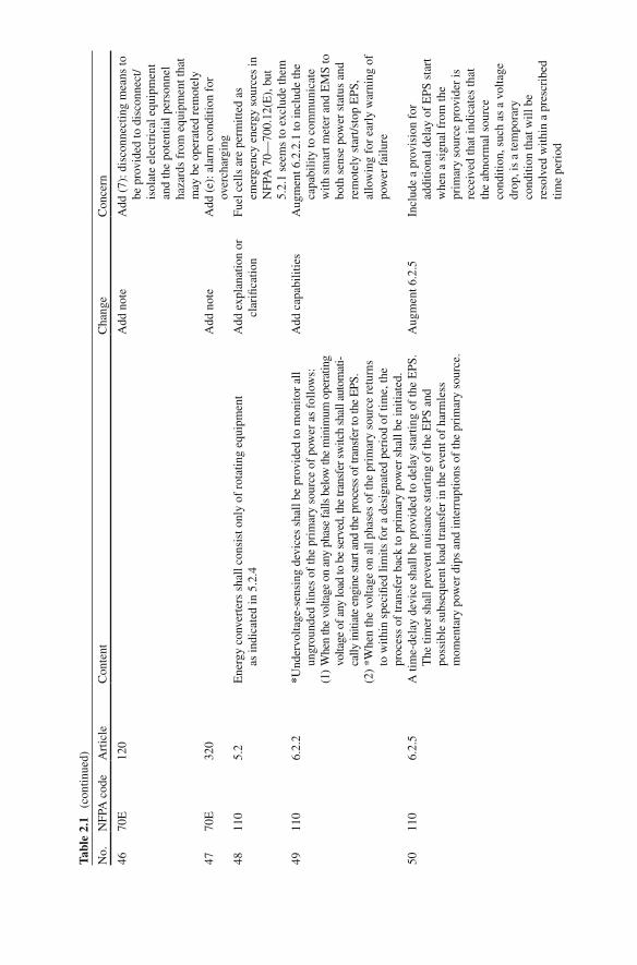
No.
N
FPA
cod
e A
rtic
le
Con
tent
C
hang
e C
once
rn
46
70E
12
0 A
dd n
ote
Add
(7)
: dis
conn
ectin
g m
eans
to
be p
rovi
ded
to d
isco
nnec
t/is
olat
e el
ectr
ical
equ
ipm
ent
and
the
pote
ntia
l per
sonn
el
haza
rds
from
equ
ipm
ent t
hat
may
be
oper
ated
rem
otel
y 47
70
E
320
Add
not
e A
dd (
e): a
larm
con
ditio
n fo
r ov
erch
argi
ng
48
110
5.2
Ene
rgy
conv
erte
rs s
hall
cons
ist o
nly
of r
otat
ing
equi
pmen
t as
indi
cate
d in
5.2
.4
Add
exp
lana
tion
or
clar
i fi ca
tion
Fuel
cel
ls a
re p
erm
itted
as
emer
genc
y en
ergy
sou
rces
in
NFP
A 7
0—70
0.12
(E),
but
5.
2.1
seem
s to
exc
lude
them
49
11
0 6.
2.2
* Und
ervo
ltage
-sen
sing
dev
ices
sha
ll be
pro
vide
d to
mon
itor
all
ungr
ound
ed li
nes
of th
e pr
imar
y so
urce
of
pow
er a
s fo
llow
s:
Add
cap
abili
ties
Aug
men
t 6.2
.2.1
to in
clud
e th
e ca
pabi
lity
to c
omm
unic
ate
with
sm
art m
eter
and
EM
S to
bo
th s
ense
pow
er s
tatu
s an
d re
mot
ely
star
t/sto
p E
PS,
allo
win
g fo
r ea
rly
war
ning
of
pow
er f
ailu
re
(1)
Whe
n th
e vo
ltage
on
any
phas
e fa
lls b
elow
the
min
imum
ope
ratin
g vo
ltage
of a
ny lo
ad to
be
serv
ed, t
he tr
ansf
er s
witc
h sh
all a
utom
ati-
cally
initi
ate
engi
ne s
tart
and
the
proc
ess
of tr
ansf
er to
the
EPS
. (2
) *W
hen
the
volta
ge o
n al
l pha
ses
of th
e pr
imar
y so
urce
ret
urns
to
with
in s
peci
fi ed
limits
for
a d
esig
nate
d pe
riod
of
time,
the
proc
ess
of tr
ansf
er b
ack
to p
rim
ary
pow
er s
hall
be in
itiat
ed.
50
110
6.2.
5 A
tim
e-de
lay
devi
ce s
hall
be p
rovi
ded
to d
elay
sta
rtin
g of
the
EPS
. T
he ti
mer
sha
ll pr
even
t nui
sanc
e st
artin
g of
the
EPS
and
po
ssib
le s
ubse
quen
t loa
d tr
ansf
er in
the
even
t of
harm
less
m
omen
tary
pow
er d
ips
and
inte
rrup
tions
of
the
prim
ary
sour
ce.
Aug
men
t 6.2
.5
Incl
ude
a pr
ovis
ion
for
addi
tiona
l del
ay o
f E
PS s
tart
w
hen
a si
gnal
fro
m th
e pr
imar
y so
urce
pro
vide
r is
re
ceiv
ed th
at in
dica
tes
that
th
e ab
norm
al s
ourc
e co
nditi
on, s
uch
as a
vol
tage
dr
op, i
s a
tem
pora
ry
cond
ition
that
will
be
reso
lved
with
in a
pre
scri
bed
time
peri
od
Tabl
e 2.
1 (c
ontin
ued)
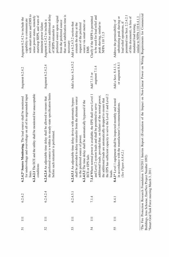
No.
N
FPA
cod
e A
rtic
le
Con
tent
C
hang
e C
once
rn
51
111
6.2.
4.2
6.2.
4.2*
Sou
rce
Mon
itor
ing.
The
load
sou
rce
shal
l be
mon
itore
d fo
r un
derv
olta
ge a
nd o
verv
olta
ge o
n al
l of
its u
ngro
unde
d in
put
lines
.
Aug
men
t 6.2
.4.2
A
ugm
ent 6
.2.4
.2 to
incl
ude
the
capa
bilit
y to
com
mun
icat
e w
ith s
mar
t met
er a
nd E
MS
to
sens
e po
wer
sta
tus,
rem
otel
y st
art/s
top
SEPS
, and
war
n of
im
min
ent p
ower
fai
lure
6.2.
4.2.
1 T
he E
CE
and
the
utili
ty s
hall
be m
onito
red
for u
nacc
epta
ble
cond
ition
s
52
111
6.2.
4.2.
4 6.
2.4.
2.4
An
adju
stab
le ti
me
dela
y sh
all b
e al
low
ed to
ens
ure
that
th
e pr
efer
red
sour
ce is
with
in it
s st
eady
-sta
te s
peci
fi cat
ion
limits
be
fore
suc
h re
tran
sfer
is p
erfo
rmed
.
Aug
men
t 6.2
.4.2
.4
Aug
men
t 6.2
.4.2
to in
clud
e a
prov
isio
n fo
r ad
ditio
nal d
elay
of
SE
PS r
etra
nsfe
r to
pr
efer
red
sour
ce u
pon
sign
al
from
the
pref
erre
d so
urce
th
at s
uch
stab
iliza
tion
time
is
nece
ssar
y 53
11
1 6.
2.4.
5.1
6.2.
4.5.
1 A
n ad
just
able
tim
e de
lay
devi
ce w
ith a
utom
atic
byp
ass
shal
l be
prov
ided
to d
elay
ret
rans
fer
from
the
alte
rnat
e so
urce
to
the
pref
erre
d so
urce
of
pow
er.
Add
a S
ect.
6.2.
4.5.
2 A
dd a
6.2
.4.5
.2 s
ectio
n th
at
exte
nds
the
dela
y at
the
requ
est o
f th
e pr
efer
red
sour
ce v
ia s
mar
t met
er o
r E
MS
6.2.
4.5.
2 T
he ti
me
dela
y sh
all b
e au
tom
atic
ally
byp
asse
d if
the
EC
E o
r E
PS f
ails
54
11
1 7.
1.4
7.1.
4 W
here
nor
mal
pow
er is
ava
ilabl
e, th
e E
PS s
hall
serv
e L
evel
1
and
Lev
el 2
sys
tem
load
s an
d sh
all b
e pe
rmitt
ed to
ser
ve
addi
tiona
l loa
ds, p
rovi
ded
that
, on
failu
re o
f th
e no
rmal
pow
er,
the
addi
tiona
l loa
ds a
re a
utom
atic
ally
dro
pped
to e
nsur
e th
at
the
EPS
has
suf
fi cie
nt c
apac
ity to
ser
ve th
e L
evel
1 a
nd L
evel
2
load
s.
Add
7.1
.5 o
r au
gmen
t 7.1
.4
Cla
rify
if th
e SE
PS is
per
mitt
ed
to b
e us
ed f
or lo
ad r
elie
f an
d pe
ak s
havi
ng, s
imila
r to
N
FPA
110
7.1
.5
55
111
8.4.
1 8.
4.1*
Lev
el 1
equ
ipm
ent s
hall
be in
spec
ted
mon
thly
and
test
ed
in a
ccor
danc
e w
ith th
e m
anuf
actu
rer’
s re
com
men
datio
ns.
(See
Fig
ure
A.8
.4.2
.)
Add
a S
ect.
8.4.
1.1,
or
aug
men
t 8.4
.1
Add
ress
the
perm
issi
bilit
y of
su
bstit
utin
g pe
ak s
havi
ng o
r lo
ad r
elie
f op
erat
ions
, if
perm
itted
(se
e Se
ct. 2
.2.4
.2.1
of
this
doc
umen
t), i
n lie
u of
m
anda
ted
load
test
ing,
si
mila
r to
NFP
A 1
10 8
.4.1
.1
a The
Fir
e Pr
otec
tion
Res
earc
h Fo
unda
tion
1/30
/201
1 In
teri
m R
epor
t (E
valu
atio
n of
the
Im
pact
on
Non
-Lin
ear
Pow
er o
n W
irin
g R
equi
rem
ents
for
Com
mer
cial
B
uild
ings
, Jen
s Sc
hoen
e, E
nerN
ex P
roje
ct N
umbe
r 10
92)
b Sm
art G
rid
Task
For
ce m
eetin
g M
arch
3, 2
011
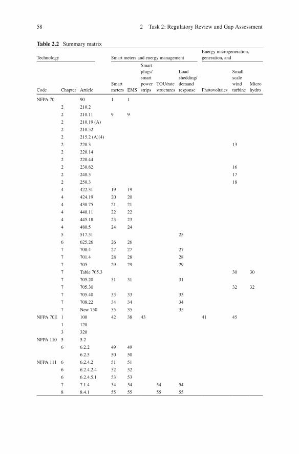
58 2 Task 2: Regulatory Review and Gap Assessment
Table 2.2 Summary matrix
Technology Smart meters and energy management Energy microgeneration, generation, and
Code Chapter Article Smart meters EMS
Smart plugs/smart power strips
TOU/rate structures
Load shedding/demand response Photovoltaics
Small scale wind turbine
Micro hydro
NFPA 70 90 1 1
2 210.2
2 210.11 9 9
2 210.19 (A)
2 210.52
2 215.2 (A)(4)
2 220.3 13
2 220.14
2 220.44
2 230.82 16
2 240.3 17
2 250.3 18
4 422.31 19 19
4 424.19 20 20
4 430.75 21 21
4 440.11 22 22
4 445.18 23 23
4 480.5 24 24
5 517.31 25
6 625.26 26 26
7 700.4 27 27 27
7 701.4 28 28 28
7 705 29 29 29
7 Table 705.3 30 30
7 705.20 31 31 31
7 705.30 32 32
7 705.40 33 33 33
7 708.22 34 34 34
7 New 750 35 35 35
NFPA 70E 1 100 42 38 43 41 45
1 120
3 320
NFPA 110 5 5.2
6 6.2.2 49 49
6.2.5 50 50
NFPA 111 6 6.2.4.2 51 51
6 6.2.4.2.4 52 52
6 6.2.4.5.1 53 53
7 7.1.4 54 54 54 54
8 8.4.1 55 55 55 55
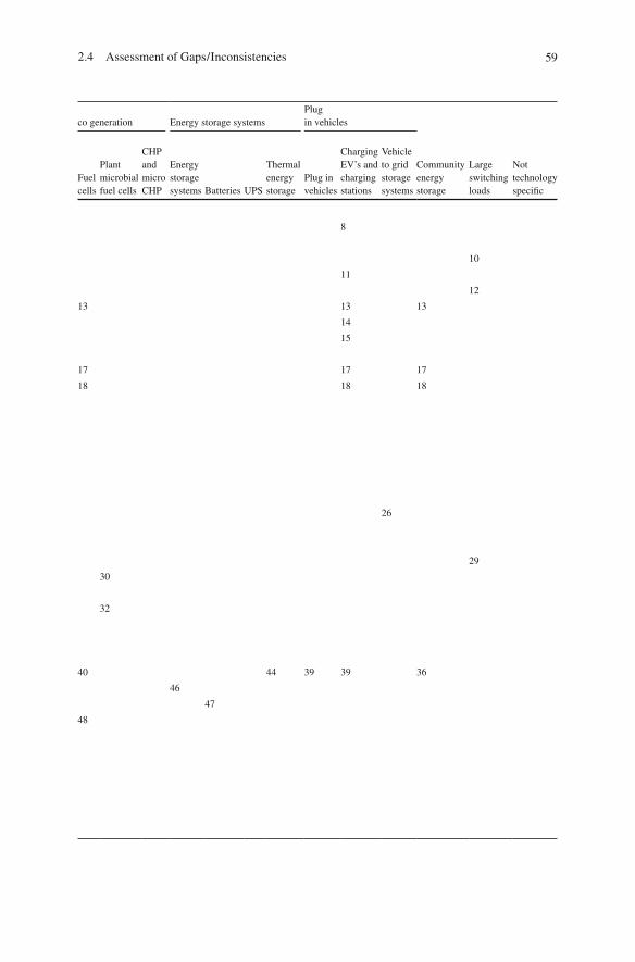
592.4 Assessment of Gaps/Inconsistencies
co generation Energy storage systems Plug in vehicles
Community energy storage
Large switching loads
Not technology speci fi c
Fuel cells
Plant microbial fuel cells
CHP and micro CHP
Energy storage systems Batteries UPS
Thermal energy storage
Plug in vehicles
Charging EV’s and charging stations
Vehicle to grid storage systems
8
10
11
12
13 13 13
14
15
17 17 17
18 18 18
26
29
30
32
40 44 39 39 36
46
47
48
60 2 Task 2: Regulatory Review and Gap Assessment
2.5 Summary Matrix
Table 2.2 links the recommended code revisions to technologies that evolved to prompt the change. At the intersection of a technology and code section is a number corresponding to the “No.” column in Table 2.1 , above.
61L. Simonian et al., Smart Grid and NFPA Electrical Safety Codes and Standards, SpringerBriefs in Fire, DOI 10.1007/978-1-4614-3948-6_3, © Fire Protection Research Foundation 2011
The fi ndings of Tasks 1 and 2 were presented to relevant NEC panel leaders and other key NFPA technical committee members at a 2-day workshop to gather perspectives based upon their individual expertise and experience gained through participation in NEC-related activities. The workshop was conducted on March 14 and 15 at the One Washington Circle Hotel Washington, DC. Workshop comments related to Task 1 were added to the existing Appendix A , Task 1 Comment Resolution Form. Workshop comments related to Task 2 were used to create a new Appendix B , Task 2 Comment Resolution Form. The Task 1 and 2 report was revised, incorporating these comments.
Chapter 3 Task 3: Workshop Presentation
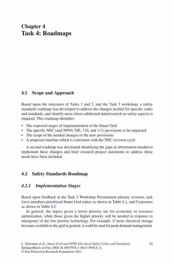
63L. Simonian et al., Smart Grid and NFPA Electrical Safety Codes and Standards, SpringerBriefs in Fire, DOI 10.1007/978-1-4614-3948-6_4, © Fire Protection Research Foundation 2011
4.1 Scope and Approach
Based upon the outcomes of Tasks 1 and 2, and the Task 3 workshop, a safety standards roadmap was developed to address the changes needed for speci fi c codes and standards, and identify areas where additional data/research on safety aspects is required. This roadmap identi fi es:
The expected stages of implementation of the Smart Grid • The speci fi c NEC (and NFPA 70E, 110, and 111) provisions to be impacted • The scope of the needed changes or the new provisions • A proposed timeline which is consistent with the NEC revision cycle •
A second roadmap was developed identifying the gaps in information needed to implement these changes and brief research project statements to address those needs have been included.
4.2 Safety Standards Roadmap
4.2.1 Implementation Stages
Based upon feedback at the Task 3 Workshop Presentation plenary sessions, task force members prioritized Smart Grid topics as shown in Table 4.1 , and Customers as shown in Table 4.2 :
In general, the topics given a lower priority are for economic or resource optimization, while those given the higher priority will be needed in response to emergence of the low priority technology. For example, if more electrical storage becomes available to the grid in general, it could be used for peak demand management.
Chapter 4 Task 4: Roadmaps
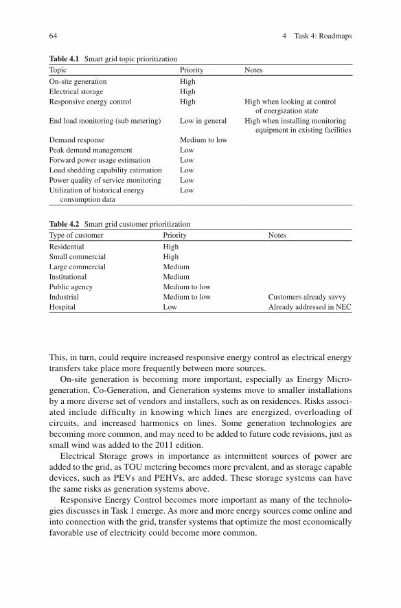
64 4 Task 4: Roadmaps
Table 4.1 Smart grid topic prioritization
Topic Priority Notes
On-site generation High Electrical storage High Responsive energy control High High when looking at control
of energization state End load monitoring (sub metering) Low in general High when installing monitoring
equipment in existing facilities Demand response Medium to low Peak demand management Low Forward power usage estimation Low Load shedding capability estimation Low Power quality of service monitoring Low Utilization of historical energy
consumption data Low
Table 4.2 Smart grid customer prioritization
Type of customer Priority Notes
Residential High Small commercial High Large commercial Medium Institutional Medium Public agency Medium to low Industrial Medium to low Customers already savvy Hospital Low Already addressed in NEC
This, in turn, could require increased responsive energy control as electrical energy transfers take place more frequently between more sources.
On-site generation is becoming more important, especially as Energy Micro-generation, Co-Generation, and Generation systems move to smaller installations by a more diverse set of vendors and installers, such as on residences. Risks associ-ated include dif fi culty in knowing which lines are energized, overloading of circuits, and increased harmonics on lines. Some generation technologies are becoming more common, and may need to be added to future code revisions, just as small wind was added to the 2011 edition.
Electrical Storage grows in importance as intermittent sources of power are added to the grid, as TOU metering becomes more prevalent, and as storage capable devices, such as PEVs and PEHVs, are added. These storage systems can have the same risks as generation systems above.
Responsive Energy Control becomes more important as many of the technolo-gies discusses in Task 1 emerge. As more and more energy sources come online and into connection with the grid, transfer systems that optimize the most economically favorable use of electricity could become more common.
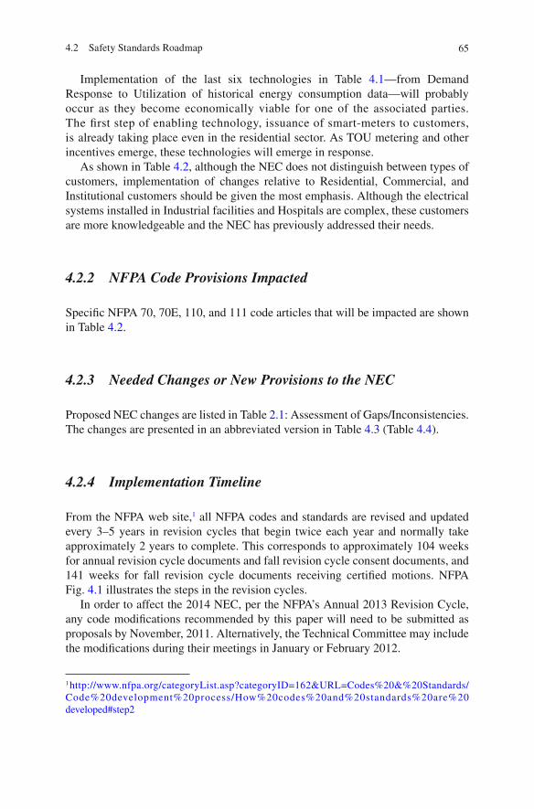
654.2 Safety Standards Roadmap
Implementation of the last six technologies in Table 4.1 —from Demand Response to Utilization of historical energy consumption data—will probably occur as they become economically viable for one of the associated parties. The fi rst step of enabling technology, issuance of smart-meters to customers, is already taking place even in the residential sector. As TOU metering and other incentives emerge, these technologies will emerge in response.
As shown in Table 4.2 , although the NEC does not distinguish between types of customers, implementation of changes relative to Residential, Commercial, and Institutional customers should be given the most emphasis. Although the electrical systems installed in Industrial facilities and Hospitals are complex, these customers are more knowledgeable and the NEC has previously addressed their needs.
4.2.2 NFPA Code Provisions Impacted
Speci fi c NFPA 70, 70E, 110, and 111 code articles that will be impacted are shown in Table 4.2 .
4.2.3 Needed Changes or New Provisions to the NEC
Proposed NEC changes are listed in Table 2.1 : Assessment of Gaps/Inconsistencies. The changes are presented in an abbreviated version in Table 4.3 (Table 4.4 ).
4.2.4 Implementation Timeline
From the NFPA web site, 1 all NFPA codes and standards are revised and updated every 3–5 years in revision cycles that begin twice each year and normally take approximately 2 years to complete. This corresponds to approximately 104 weeks for annual revision cycle documents and fall revision cycle consent documents, and 141 weeks for fall revision cycle documents receiving certi fi ed motions. NFPA Fig. 4.1 illustrates the steps in the revision cycles.
In order to affect the 2014 NEC, per the NFPA’s Annual 2013 Revision Cycle, any code modi fi cations recommended by this paper will need to be submitted as proposals by November, 2011. Alternatively, the Technical Committee may include the modi fi cations during their meetings in January or February 2012.
1 http://www.nfpa.org/categoryList.asp?categoryID=162&URL=Codes%20&%20Standards/Code%20development%20process/How%20codes%20and%20standards%20are%20developed#step2
66 4 Task 4: Roadmaps
Code Chapter Article
NFPA 70 90.2 (A) 2 210.2 2 210.11 2 210.19 (A) 2 210.52 2 215.2 (A)(4) 2 220.3 2 220.14 2 220.44 2 230.82 2 240.3 2 250.3 4 422.31 4 424.19 4 430.75 4 440.11 4 445.18 4 480.5 5 517.31 6 625.26 7 700.4 7 701.4 7 705 7 Table 705.3 7 705.20 7 705.30 7 705.40 7 708.22 7 New 750
NFPA 70E 1 100 1 120 3 320
NFPA 110 5 5.2 6 6.2.2 6 6.2.5
NFPA 111 6 6.2.4.2 6 6.2.4.2.4 6 6.2.4.5.1 7 7.1.4 8 8.4.1
Table 4.3 NFPA code impact
Any recommendations that require further research will still have to meet one of the above two dates. The research will have to be completed in time to be included in the Report for Proposals. If insuf fi cient data is collected by that time, but will be available before April 2013, if the recommendation has been included in a Report for Proposal, it can be amended during the Tech Session.
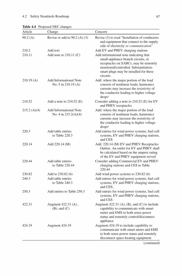
674.2 Safety Standards Roadmap
Table 4.4 Proposed NEC changes
Article Change Concern
90.2 (A) Revise or add to 90.2 (A) (3) Revise (3) to read “Installation of conductors and equipment that connect to the supply side of electricity or communication ”
210.2 Add text Add EV and PHEV charging stations 210.11 Add note to 210.11 (C) Add informational note indicating that
small-appliance branch circuits, or receptacles on SABCs, may be remotely monitored/controlled. Substantiation- smart plugs may be installed for these circuits
210.19 (A) Add Informational Note No. 5 in 210.19 (A)
Add: where the major portion of the load consists of nonlinear loads, harmonics currents may increase the resistivity of the conductor leading to higher voltage drops a
210.52 Add a note to 210.52 (E) Consider adding a note to 210.52 (E) for EV and PHEV receptacles
215.2 (A)(4) Add Informational Note No. 4 in 215.2(A)(4)
Add: where the major portion of the load consists of nonlinear loads, harmonics currents may increase the resistivity of the conductor leading to higher voltage drops a
220.3 Add table entries to Table 220.3
Add entries for wind power systems, fuel cell systems, EV and PHEV charging stations, and CES
220.14 Add 220.14 (M) Add: 220.14 (M) EV and PHEV Receptacles Outlets. An outlet for EV and PHEV shall be calculated based on the ampere rating of the EV and PHEV equipment served
220.44 Add table entries to Table 220.44
Consider adding Commercial EV and PHEV charging stations and CES to Table 220.44
230.82 Add to 230.82 (6) Add wind power systems to 230.82 (6) 240.3 Add table entries
to Table 240.3 Add entries for wind power systems, fuel cell
systems, EV and PHEV charging stations, and CES.
250.3 Add entries to Table 250.3 Add entries for wind power systems, fuel cell systems, EV and PHEV charging stations, and CES
422.31 Augment 422.31 (A) , (B), and (C)
Augment 422.31 (A), (B), and (C) to include capability to communicate with smart meter and EMS to both sense power status and remotely control/disconnect appliance
424.19 Augment 424.19 Augment 424.19 to include capability to communicate with smart meter and EMS to both sense power status and remotely disconnect space-heating equipment
(continued)
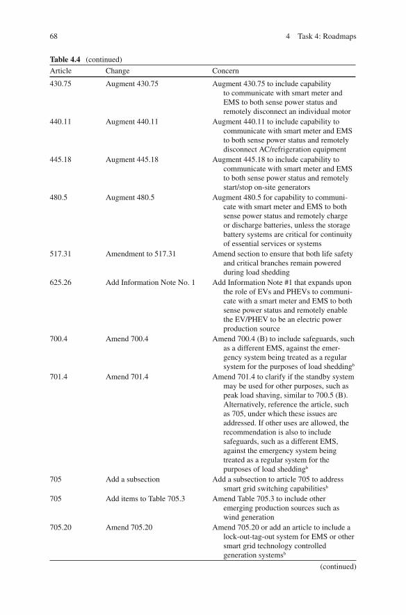
68 4 Task 4: Roadmaps
Article Change Concern
430.75 Augment 430.75 Augment 430.75 to include capability to communicate with smart meter and EMS to both sense power status and remotely disconnect an individual motor
440.11 Augment 440.11 Augment 440.11 to include capability to communicate with smart meter and EMS to both sense power status and remotely disconnect AC/refrigeration equipment
445.18 Augment 445.18 Augment 445.18 to include capability to communicate with smart meter and EMS to both sense power status and remotely start/stop on-site generators
480.5 Augment 480.5 Augment 480.5 for capability to communi-cate with smart meter and EMS to both sense power status and remotely charge or discharge batteries, unless the storage battery systems are critical for continuity of essential services or systems
517.31 Amendment to 517.31 Amend section to ensure that both life safety and critical branches remain powered during load shedding
625.26 Add Information Note No. 1 Add Information Note #1 that expands upon the role of EVs and PHEVs to communi-cate with a smart meter and EMS to both sense power status and remotely enable the EV/PHEV to be an electric power production source
700.4 Amend 700.4 Amend 700.4 (B) to include safeguards, such as a different EMS, against the emer-gency system being treated as a regular system for the purposes of load shedding b
701.4 Amend 701.4 Amend 701.4 to clarify if the standby system may be used for other purposes, such as peak load shaving, similar to 700.5 (B). Alternatively, reference the article, such as 705, under which these issues are addressed. If other uses are allowed, the recommendation is also to include safeguards, such as a different EMS, against the emergency system being treated as a regular system for the purposes of load shedding b
705 Add a subsection Add a subsection to article 705 to address smart grid switching capabilities b
705 Add items to Table 705.3 Amend Table 705.3 to include other emerging production sources such as wind generation
705.20 Amend 705.20 Amend 705.20 or add an article to include a lock-out-tag-out system for EMS or other smart grid technology controlled generation systems b
Table 4.4 (continued)
(continued)

694.2 Safety Standards Roadmap
Article Change Concern
705.30 Add items to 705.30 Add additional letter items, (F), (G), etc., to include other emerging production sources such as wind generation
705.40 Amend 705.40 Amend 705.40 to add scenarios as appropriate to include actions that should be taken by an EMS or other smart grid switching system in the event of primary power loss
708.22 Amend 708.22 (B) Amend 708.22 (B) to include safeguards, such as a different EMS, against the emergency system being treated as a regular system for the purposes of load shedding
None Add an article Consider adding a new article 750 that references code and rules for EMS and other load management systems
a The Fire Protection Research Foundation 1/30/2011 Interim Report (Evaluation of the Impact on Non-Linear Power on Wiring Requirements for Commercial Buildings, Jens Schoene, EnerNex Project Number 1092) b Smart Grid Task Force meeting March 3, 2011
Table 4.4 (continued)
Fig. 4.1 NFPA codes and standards making process ( http://www.nfpa.org/categoryList.asp?categoryID=162&URL=Codes%20&%20Standards/Code%20development%20process/How%20codes%20and%20standards%20are%20developed#step2 )
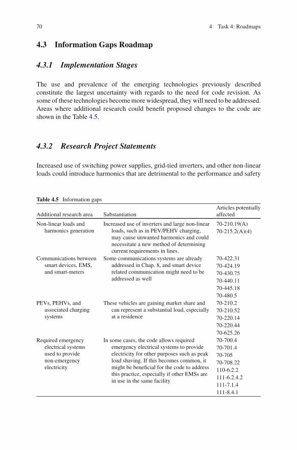
70 4 Task 4: Roadmaps
4.3 Information Gaps Roadmap
4.3.1 Implementation Stages
The use and prevalence of the emerging technologies previously described constitute the largest uncertainty with regards to the need for code revision. As some of these technologies become more widespread, they will need to be addressed. Areas where additional research could bene fi t proposed changes to the code are shown in the Table 4.5 .
4.3.2 Research Project Statements
Increased use of switching power supplies, grid-tied inverters, and other non-linear loads could introduce harmonics that are detrimental to the performance and safety
Table 4.5 Information gaps
Additional research area Substantiation Articles potentially affected
Non-linear loads and harmonics generation
Increased use of inverters and large non-linear loads, such as in PEV/PEHV charging, may cause unwanted harmonics and could necessitate a new method of determining current requirements in lines.
70-210.19(A) 70-215.2(A)(4)
Communications between smart devices, EMS, and smart-meters
Some communications systems are already addressed in Chap. 8, and smart device related communication might need to be addressed as well
70-422.31 70-424.19 70-430.75 70-440.11 70-445.18 70-480.5
PEVs, PEHVs, and associated charging systems
These vehicles are gaining market share and can represent a substantial load, especially at a residence
70-210.2 70-210.52 70-220.14 70-220.44 70-625.26
Required emergency electrical systems used to provide non-emergency electricity
In some cases, the code allows required emergency electrical systems to provide electricity for other purposes such as peak load shaving. If this becomes common, it might be bene fi cial for the code to address this practice, especially if other EMSs are in use in the same facility
70-700.4 70-701.4 70-705 70-708.22 110-6.2.2 111-6.2.4.2 111-7.1.4 111-8.4.1
714.3 Information Gaps Roadmap
of circuits and protective systems. Research to determine if the magnitude of these issues warrants additional or modi fi ed code entries is recommended.
It would be bene fi cial to periodically survey what technologies are taking the lead in terms of smart grid device production and implementation. Keeping an eye on emerging smart device communications could allow more targeted code articles to be developed as the technology emerges. For example, as residential EMS with TOU metering becomes more common, discovering the dominate method of communication to the utility will allow for development of code articles speci fi cally addressing these requirements.
PEVs and PEHVs are currently being mass produced and sold to the public by two major car manufacturers in addition to smaller niche market manufacturers. These vehicles could create a signi fi cant increase in electricity usage by individual residences, and their charging systems might add harmonics to residential circuits. Furthermore, most residential charging systems (such as a conventional 120 V duplex receptacle) are not currently “smart.” As charging systems become “smarter,” especially if these vehicles are used for general electricity storage, investigation into the power requirements and abilities of these vehicles will allow the code to stipu-late requirements for safe vehicle charging and discharging.
The code allows some required emergency electricity systems to generate non-emergency power. This sometimes can be used to meet periodic testing require-ments. As more and more systems become smart, the practice of non-emergency use of emergency systems could increase in frequency. In that case, additional research could determine if more code provisions are needed to address any emerg-ing hazards, and conversely if more required emergency systems can be safely allowed to supply electricity.

73L. Simonian et al., Smart Grid and NFPA Electrical Safety Codes and Standards, SpringerBriefs in Fire, DOI 10.1007/978-1-4614-3948-6, © Fire Protection Research Foundation 2011
Appendices
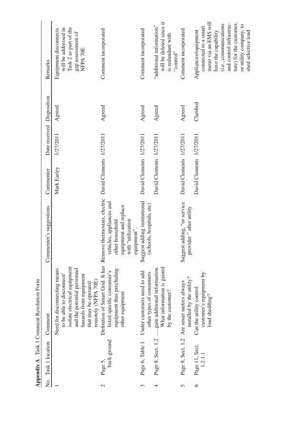
No.
Ta
sk 1
loca
tion
Com
men
t C
omm
ente
r’s
sugg
estio
ns
Com
men
ter
Dat
e re
ceiv
ed
Dis
posi
tion
Rem
arks
1 N
eed
for
disc
onne
ctin
g m
eans
to
be
able
to d
isco
nnec
t/is
olat
e el
ectr
ical
equ
ipm
ent
and
the
pote
ntia
l per
sonn
el
haza
rds
from
equ
ipm
ent
that
may
be
oper
ated
re
mot
ely
(NFP
A 7
0E)
Mar
k E
arle
y 1/
27/2
011
Agr
eed
Equ
ipm
ent d
isco
nnec
ts
will
be
addr
esse
d in
Ta
sk 2
as
part
of
the
gap
asse
ssm
ent o
f N
FPA
70E
2 Pa
ge 5
, ba
ck-g
roun
d D
e fi ni
tion
of S
mar
t Gri
d. I
t has
lis
ted
spec
i fi c
cons
umer
’s
equi
pmen
t thu
s pr
eclu
ding
ot
her
equi
pmen
t
Rem
ove
ther
mos
tats
, ele
ctri
c ve
hicl
es, a
pplia
nces
and
ot
her
hous
ehol
d eq
uipm
ent a
nd r
epla
ce
with
“ut
iliza
tion
equi
pmen
t”.
Dav
id C
lem
ents
1/
27/2
011
Agr
eed
Com
men
t inc
orpo
rate
d
3 Pa
ge 6
, Tab
le 1
U
nder
cus
tom
ers
need
to a
dd
othe
r ty
pes
of c
onsu
mer
s Su
gges
t add
ing
inst
itutio
nal
(sch
ools
, hos
pita
ls, e
tc)
Dav
id C
lem
ents
1/
27/2
011
Agr
eed
Com
men
t inc
orpo
rate
d
4 Pa
ge 8
, Sec
t. 1.
2 .…
gain
add
ition
al in
form
atio
n.
Wha
t inf
orm
atio
n is
gai
ned
by th
e cu
stom
er?
Dav
id C
lem
ents
1/
27/2
011
Agr
eed
“add
ition
al in
form
atio
n”
will
be
dele
ted
sinc
e it
is r
edun
dant
with
“c
ontr
ol”
5 Pa
ge 8
, Sec
t. 1.
2 A
re s
mar
t met
ers
alw
ays
inst
alle
d by
the
utili
ty?
Sugg
est a
ddin
g, “
or s
ervi
ce
prov
ider
” a
fter
util
ity
Dav
id C
lem
ents
1/
27/2
011
Agr
eed
Com
men
t inc
orpo
rate
d
6 Pa
ge 1
1, S
ect.
1.2.
1.1
Can
the
utili
ty c
ontr
ol
cust
omer
’s e
quip
men
t by
load
she
ddin
g?
Dav
id C
lem
ents
1/
27/2
011
Cla
ri fi e
d A
pplia
nces
/equ
ipm
ent
conn
ecte
d to
a s
mar
t m
eter
via
an
EM
S w
ill
have
the
capa
bilit
y (i
.e.,
com
mun
icat
ions
an
d co
ntro
l inf
rast
ruc-
ture
) fo
r th
e cu
stom
er,
or u
tility
com
pany
, to
shed
sel
ectiv
e lo
ad
App
endi
x A
Ta
sk 1
Com
men
t Res
olut
ion
Form

7 Pa
ge 1
1, S
ect.
1.2.
1.2
“whe
n us
age
is lo
w is
” R
epla
ce w
ith “
whe
n de
man
d on
the
utili
ty s
yste
m is
lo
wer
”
Dav
id C
lem
ents
1/
27/2
011
Agr
eed
Com
men
t inc
orpo
rate
d
8 Pa
ges
11, 1
2 Se
ct. 1
.2.1
.2
I do
not
und
erst
and
why
TO
U
rate
s ar
e an
issu
e w
ith
rene
wab
le e
nerg
y so
urce
s,
plea
se e
xpla
in
Dav
id C
lem
ents
1/
27/2
011
Agr
eed
“Ren
ewab
le e
nerg
y so
urce
” ha
s be
en
chan
ged
to “
cust
omer
- ge
nera
ted”
ene
rgy
sour
ce
9 Pa
ge 1
2, S
ect.
1.2.
1.3
Do
inte
rrup
tible
rat
es o
nly
appl
y to
indu
stri
al
cust
omer
s?
If th
is is
so
than
nee
d to
id
entif
y on
ly in
dust
rial
. ad
d “
Indu
stri
al”
befo
re
cust
omer
Dav
id C
lem
ents
1/
27/2
011
Cla
ri fi e
d A
low
er r
ate
stru
ctur
e (i
n ex
chan
ge f
or u
tility
co
ntro
l of
load
sh
eddi
ng)
is c
urre
ntly
av
aila
ble
for
man
y co
mm
erci
al c
usto
mer
s an
d, in
som
e lo
catio
ns,
for
cont
rol o
f A
C
syst
ems
of r
esid
entia
l cu
stom
ers
10
Page
12,
Sec
t. 1.
2.1.
3 U
nder
bul
let i
tem
s ne
ed to
add
ad
ditio
nal i
tem
A
dd b
ulle
t “Sm
art c
harg
ing
for
elec
tric
ther
mal
st
orag
e sy
stem
s”
(exa
mpl
e: in
gro
und
heat
ing
syst
ems,
uni
t he
ater
s)
Dav
id C
lem
ents
1/
27/2
011
Agr
eed
Com
men
t inc
orpo
rate
d
11
Page
12,
Sec
t. 1.
2.1.
3 L
ast p
arag
raph
. Not
sur
e w
hat
impa
ct s
mar
t met
er
tech
nolo
gies
has
on
AFC
I’s
& G
FCI’
s
Plea
se e
xpla
in
Dav
id C
lem
ents
1/
27/2
011
Agr
eed
Para
grap
h ha
s be
en
mod
i fi ed
del
etin
g G
FCIs
and
exp
lain
ing
the
susc
eptib
ility
of
AFC
Is to
sm
art
met
er’s
wir
eles
s tr
ansm
issi
on
(con
tinue
d)
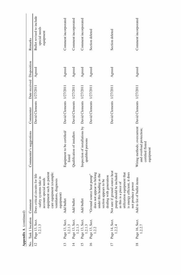
12
Page
13,
Sec
t. 1.
2.1.
3 D
oes
criti
cal c
ircu
its f
or li
fe
-saf
ety
syst
ems
take
in
acco
unt s
peci
al n
eeds
eq
uipm
ent s
uch
as p
atie
nt
care
equ
ipm
ent (
exam
ple:
ve
ntila
tors
, dia
gnos
is
equi
pmen
t)
Dav
id C
lem
ents
1/
27/2
011
Agr
eed
Bul
let r
evis
ed to
incl
ude
spec
ial n
eeds
eq
uipm
ent
13
Page
13,
Sec
t. 1.
2.1.
3 A
dd b
ulle
t E
quip
men
t to
be c
erti fi
ed/
liste
d D
avid
Cle
men
ts
1/27
/201
1 A
gree
d C
omm
ent i
ncor
pora
ted
14
Page
13,
Sec
t. 1.
2.1.
3 A
dd b
ulle
t Q
uali fi
catio
n of
inst
alle
rs
Dav
id C
lem
ents
1/
27/2
011
Agr
eed
Com
men
t inc
orpo
rate
d
15
Page
13,
Sec
t. 1.
2.1.
3 A
dd b
ulle
t In
spec
tion
of in
stal
latio
ns b
y qu
ali fi
ed p
erso
ns
Dav
id C
lem
ents
1/
27/2
011
Agr
eed
Com
men
t inc
orpo
rate
d
16
Page
13,
Sec
t. 1.
2.2
“Gro
und
sour
ce h
eat p
ump”
do
es n
ot a
ppea
r to
bel
ong
unde
r th
is h
eadi
ng a
s th
e se
ctio
n ap
pear
s to
be
deal
ing
with
gen
erat
ion
Dav
id C
lem
ents
1/
27/2
011
Agr
eed
Sect
ion
dele
ted
17
Page
14,
Sec
t. 1.
2.2.
4 N
ot s
ure
if g
roun
d so
urce
hea
t pu
mp
shou
ld b
e in
clud
ed
as th
is is
a p
iece
of
utili
zatio
n eq
uipm
ent t
hat
is e
nerg
y ef
fi cie
nt, i
t doe
s no
t pro
duce
pow
er
Dav
id C
lem
ents
1/
27/2
011
Agr
eed
Sect
ion
dele
ted
18
Page
16,
Sec
t. 1.
2.2.
7 A
dd to
list
of
bulle
t ite
ms
Wir
ing
met
hods
; ove
rcur
rent
an
d ov
erlo
ad p
rote
ctio
n;
cert
i fi ed
/lis
ted
equi
pmen
t
Dav
id C
lem
ents
1/
27/2
011
Agr
eed
Com
men
t inc
orpo
rate
d
No.
Task
1 lo
catio
nC
omm
ent
Com
men
ter’
s su
gges
tions
Com
men
ter
Dat
e re
ceiv
edD
ispo
sitio
nR
emar
ks
App
endi
x A
(co
ntin
ued)
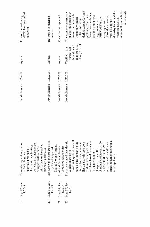
19
Page
17,
Sec
t. 1.
2.3.
3 T
herm
al e
nerg
y st
orag
e al
so
incl
udes
in g
roun
d el
ectr
ical
hea
t pan
els,
el
ectr
ic s
tora
ge h
eatin
g sy
stem
s. E
TS
heat
ers
are
equi
pped
with
cer
amic
br
icks
that
are
hea
ted
up
duri
ng o
ff p
eak
rate
s
Dav
id C
lem
ents
1/
27/2
011
Agr
eed
Ele
ctri
c th
erm
al s
tora
ge
(ET
S) h
as b
een
adde
d to
sec
tion
20
Page
18,
Sec
t. 1.
2.3.
3 N
ot s
ure
why
met
ers
are
liste
d as
pot
entia
l im
pact
of
Ene
rgy
Stor
age
syst
ems
Dav
id C
lem
ents
1/
27/2
011
Agr
eed
Ref
eren
ce to
met
erin
g re
mov
ed
21
Page
18,
Sec
t. 1.
2.3.
3 L
oad
and
Dem
and
fact
ors
shou
ld b
e ad
ded
to li
st
Dav
id C
lem
ents
1/
27/2
011
Agr
eed
Com
men
t inc
orpo
rate
d
22
Page
18,
Sec
t. 1.
2.4.
1 I’
m n
ot c
onvi
nced
that
ele
ctri
c ve
hicl
e ch
argi
ng in
re
side
ntia
l app
licat
ions
will
ha
ve a
hug
e im
pact
on
the
utili
ty d
istr
ibut
ion
syst
em.
Has
an
anal
ysis
bee
n do
ne
to s
how
wha
t im
pact
this
w
ill h
ave
base
d on
am
ount
of
ene
rgy
requ
ired
to
char
ge a
veh
icle
. If
the
char
ging
equ
ipm
ent i
s 12
0 or
120
/240
the
# of
KW
is
very
low
and
wou
ld b
e no
di
ffer
ent t
han
plug
ging
in a
sm
all a
pplia
nce
Dav
id C
lem
ents
1/
27/2
011
Cla
ri fi e
d –
this
su
bjec
t will
be
add
ress
ed
in m
ore
deta
il du
ring
Tas
k 4
The
pri
mar
y co
ncer
ns a
re
that
util
ity d
istr
ibut
ion
tran
sfor
mer
s (w
hich
co
mm
only
exc
eed
100%
util
izat
ion
duri
ng c
urre
nt d
aytim
e pe
ak u
sage
) w
ill n
o lo
nger
hav
e ni
ghtti
me
cool
ing
assu
min
g a
larg
e am
ount
of
PHE
Vs/
PEV
s ar
e ch
argi
ng a
t 240
v.
Als
o, th
ere
may
be
very
littl
e (o
r no
) di
vers
ity f
acto
r an
d th
e ch
argi
ng lo
ad w
ill
occu
r at
the
sam
e tim
e
(con
tinue
d)

23
Page
19,
Sec
t. 1.
2.5
The
re is
no
men
tion
of
com
mun
ity e
nerg
y st
orag
e fo
r co
mm
erci
al a
pplic
a-tio
ns th
at n
orm
al a
re
supp
lied
from
thre
e ph
ase
277/
480
V s
yste
ms
Dav
id C
lem
ents
1/
27/2
011
Agr
eed
Supp
ly v
olta
ge a
dded
to
sect
ion
24
Page
21,
Tab
le 2
U
nder
Sm
art M
eter
s N
eed
to in
clud
e se
curi
ty
syst
ems
and
life
supp
ort
equi
pmen
t
Dav
id C
lem
ents
1/
27/2
011
Agr
eed
Com
men
t inc
orpo
rate
d
25
Page
21,
Tab
le 2
U
nder
Ene
rgy
Mic
ro-
gene
ratio
n, C
o-ge
nera
tion
Bac
kup
gene
rato
rs a
re n
ot
norm
ally
per
mitt
ed to
su
pply
pow
er to
the
grid
Dav
id C
lem
ents
1/
27/2
011
Agr
eed
Ref
eren
ce to
cus
tom
er
back
up g
ener
atio
n cl
ari fi
ed to
be
an
exce
ptio
n to
cur
rent
pe
rmitt
ing
26
Page
21,
Tab
le 2
U
nder
Ene
rgy
Mic
ro-
gene
ratio
n, C
o-ge
nera
tion
– po
ssib
le N
EC
issu
es
Add
list
ed/c
erti fi
ed
equi
pmen
t D
avid
Cle
men
ts
1/27
/201
1 A
gree
d C
omm
ent i
ncor
pora
ted
27
Page
21,
Tab
le 2
U
nder
Ene
rgy
Stor
age
syst
ems
– po
ssib
le N
EC
issu
es
Add
ven
tilat
ion
requ
ire-
men
ts; f
ault
curr
ents
D
avid
Cle
men
ts
1/27
/201
1 A
gree
d C
omm
ent i
ncor
pora
ted
28
Page
21,
Tab
le 2
U
nder
Plu
g-in
Veh
icle
s A
dd li
sted
/cer
ti fi ed
eq
uipm
ent
Dav
id C
lem
ents
1/
27/2
011
Agr
eed
Com
men
t inc
orpo
rate
d
29
The
Tas
k 1
repo
rt a
ppea
rs to
m
eet t
he g
ener
al r
equi
re-
men
ts; h
owev
er, m
ore
dept
h is
nee
ded
in th
e in
itial
ana
lysi
s of
the
impa
cts
on s
afet
y fe
atur
es.
(par
aphr
ased
)
Will
iam
G
allo
way
1/
27/2
011
Agr
eed
Task
2 g
ap a
naly
sis
will
ad
dres
s sa
fety
fea
ture
re
quir
emen
ts/
shor
tfal
ls
No.
Task
1 lo
catio
nC
omm
ent
Com
men
ter’
s su
gges
tions
Com
men
ter
Dat
e re
ceiv
edD
ispo
sitio
nR
emar
ks
App
endi
x A
(co
ntin
ued)

30
In g
ener
al, I
wou
ld li
ke to
see
a
mor
e po
inte
d as
sess
men
t of
the
pote
ntia
lly a
ffec
ted
sect
ions
of
the
Cod
e. T
he
repo
rt d
oes
a go
od jo
b of
id
entif
ying
gen
eral
are
as o
f co
ncer
n, b
ut d
oes
not
deve
lop
thos
e ar
eas
of
conc
ern
and
does
not
eq
uate
them
to s
peci
fi c
Art
icle
s. I
rea
lize
that
this
is
not
an
easy
ass
ignm
ent.
Whi
le S
mar
t Gri
d re
late
d st
anda
rds
iden
ti fi ca
tion
and
deve
lopm
ent c
an, a
nd d
oes
occu
r w
ithou
t the
cod
e as
a
driv
er, t
he id
enti fi
catio
n of
sp
eci fi
c co
de c
hang
es
focu
ses
this
pro
cess
to
ensu
re th
at th
e in
stal
latio
n re
quir
emen
ts a
re c
ompa
t-ib
le w
ith th
e de
sign
s of
m
anuf
actu
red
equi
pmen
t. W
hile
I b
elie
ve th
at m
ore
spec
i fi ci
ty is
nee
ded
over
all,
a fe
w e
xam
ples
ar
e: (
see
31–3
6)
John
Tho
mps
on
2/1/
2011
N
oted
C
ode
asse
ssm
ent i
s cu
rren
tly b
eing
ad
dres
sed
as p
art o
f Ta
sk 2
(con
tinue
d)

31
Page
13,
Sec
t. 1.
2.1.
3 B
ulle
t 3 –
mor
e sp
eci fi
city
is
need
ed. A
re th
e is
sues
co
nduc
tor
fi ll,
circ
uit
com
patib
ility
/sep
arat
ion
of
circ
uits
, wor
kman
ship
?
John
Tho
mps
on
2/1/
2011
N
oted
T
his
subj
ect n
eeds
mor
e st
udy,
how
ever
, the
in
terf
ace
betw
een
larg
e ap
plia
nces
, E
MSs
, and
pan
el-
boar
ds/lo
ad c
ente
rs
may
req
uire
add
ition
al
pow
er o
r co
ntro
l w
irin
g 32
Pa
ge 1
3 B
ulle
t 5 –
sen
sors
– is
this
a
code
issu
e or
a s
tand
ards
is
sue?
To
som
e de
gree
, Sm
art M
eter
s ex
ist a
nd
thei
r pr
imar
y jo
b is
to
com
mun
icat
e us
age
to th
e ut
ility
for
bill
ing
purp
oses
. M
eter
s an
d ap
plia
nces
will
lik
ely
have
inte
gral
co
mm
unic
atio
n ca
pabi
lity
(bot
h se
nd a
nd r
ecei
ve).
Ju
st lo
okin
g fo
r cl
ari fi
catio
n he
re
John
Tho
mps
on
2/1/
2011
C
lari
fi ed
Bot
h co
des
and
stan
dard
s w
ill b
e af
fect
ed;
com
mun
icat
ion
prot
ocol
s w
ill in
volv
e de
velo
ping
a s
tand
ard,
w
hile
sw
itchi
ng o
f lo
ads
will
be
a co
de
issu
e
33
Page
13
Bul
let 6
– s
ame
ques
tion
as
abov
e, is
this
a c
ode
or
stan
dard
s/pe
rfor
man
ce
issu
e?
John
Tho
mps
on
2/1/
2011
C
lari
fi ed
Bot
h co
des
and
stan
dard
s w
ill b
e af
fect
ed;
com
mun
icat
ion
prot
ocol
s w
ill in
volv
e de
velo
ping
a s
tand
ard,
w
hile
sw
itchi
ng o
f lo
ads
will
be
a co
de
issu
e
No.
Task
1 lo
catio
nC
omm
ent
Com
men
ter’
s su
gges
tions
Com
men
ter
Dat
e re
ceiv
edD
ispo
sitio
nR
emar
ks
App
endi
x A
(co
ntin
ued)

34
Page
13
Bul
let 7
– h
arm
onic
s –
can
we
get m
ore
clar
i fi ca
tion?
H
arm
onic
s ar
e an
issu
e w
ith li
ne v
olta
ge d
evic
es
too.
Sw
itch
mod
e po
wer
su
pplie
s, b
alla
sts,
co
mm
unic
atio
n de
vice
s,
and
othe
r po
wer
sw
itchi
ng
devi
ces
mak
e a
case
for
us
to u
nder
stan
d an
d co
ntro
l th
e ef
fect
s of
em
issi
ons
and
nois
e
John
Tho
mps
on
2/1/
2011
C
lari
fi ed
The
con
cern
is th
at
switc
hing
load
s in
duce
ha
rmon
ics;
and
that
th
e ef
fect
of
thes
e ha
rmon
ics
need
s to
be
unde
rsto
od a
nd
addr
esse
d in
ap
prop
riat
e co
des
35
Page
13,
Sec
t. 1.
2.2
Thi
s is
nic
ely
bund
led.
Can
C
al P
oly
offe
r m
ore
anal
ysis
reg
ardi
ng s
peci
fi c
affe
cts
on th
e co
de?
John
Tho
mps
on
2/1/
2011
C
lari
fi ed
Thi
s w
ill b
e ad
dres
sed
in
Task
2, r
egul
ator
y re
view
and
gap
as
sess
men
t 36
Pa
ge 1
5–16
, Se
ct. 1
.2.2
.7
Can
Cal
Pol
y of
fer
mor
e an
alys
is r
egar
ding
the
curr
ent r
equi
rem
ents
in th
e co
de r
elat
ive
to D
C
dist
ribu
tion?
John
Tho
mps
on
2/1/
2011
C
lari
fi ed
Thi
s w
ill b
e ad
dres
sed
in
Task
2, r
egul
ator
y re
view
and
gap
as
sess
men
t
37
Ove
rall
obje
ctiv
e ne
eded
to b
e to
rai
se th
e pr
o fi le
of
the
NE
C a
nd it
s re
latio
nshi
p to
Sm
art G
rid,
whi
ch I
bel
ieve
th
e re
port
doe
s
Jim
Pau
ley
2/1/
2011
N
oted
N
o ac
tion
requ
ired
(con
tinue
d)

38
1.2.
1.3
“Pow
er o
r co
ntro
l wir
ing
may
be
req
uire
d to
tie
into
pa
nelb
oard
s/lo
ad c
ente
rs.”
T
his
seem
s to
indi
cate
that
on
wir
ed S
mar
t Gri
d sy
stem
s th
e ut
ility
con
trol
w
ires
and
pos
sibl
e co
ntro
ls
wou
ld e
nter
into
site
pa
nelb
oard
s, th
us a
llow
ing
the
utili
ty to
inst
all o
n th
e lo
ad s
ide
of th
e se
rvic
e po
int.
The
rep
ort h
as
doze
ns o
f su
ch e
xam
ples
of
whe
re u
tiliti
es m
ay s
tep
into
the
site
ele
ctri
cal
syst
em. W
ill tr
aditi
onal
site
el
ectr
ical
con
trac
tors
acc
ept
this
new
type
of
inte
rven
-tio
n in
to w
hat t
hey
perc
eive
as
“th
eir
wor
k?”
Vin
ce
Bac
law
ski
wor
ksho
p no
tes
3/16
/201
1 C
lari
fi ed.
Tex
t am
ende
d to
re
ad “
Pow
er
or c
ontr
ol
wir
ing
inst
alle
d by
li
cens
ed
elec
tric
al
cont
ract
ors
may
be
requ
ired
to ti
e in
to
pane
lboa
rds/
load
cen
ters
”
The
ass
umpt
ion
is th
at
addi
tiona
l wir
ing
may
be
nee
ded
for
indi
vidu
al lo
ads
or
HA
Ns.
The
rep
ort
does
not
mea
n to
su
gges
t tha
t uti
liti
es
wou
ld b
e th
e en
tity
to
inst
all t
his
wir
ing.
We
conc
ur w
ith th
e co
mm
ente
r th
at w
ired
in
stal
latio
ns w
ould
m
ost l
ikel
y be
pe
rfor
med
by
licen
sed
elec
tric
al c
ontr
acto
rs
39
1.2.
1.3
“HA
N te
chno
logy
in th
e ho
me
will
ena
ble
the
elec
tric
ut
ility
to b
ette
r m
atch
en
ergy
sup
ply
with
dem
and
…”
Not
true
. The
HA
N is
rea
lly
just
the
com
mun
icat
ion
netw
ork
in th
e ho
me
and
is n
ot n
orm
ally
con
-ne
cted
to th
e ut
ility
un
less
the
HA
N is
im
bedd
ed in
the
smar
t m
eter
Vin
ce
Bac
law
ski
wor
ksho
p no
tes
3/16
/201
1 C
lari
fi ed
Rev
ised
to r
ead
“HA
N
tech
nolo
gy in
the
hom
e ca
n en
able
the
elec
tric
util
ity to
bet
ter
mat
ch e
nerg
y su
pply
w
ith d
eman
d (i
f the
H
AN
com
mun
icat
es
wit
h a
Smar
t Met
er) ,
…
”
No.
Task
1 lo
catio
nC
omm
ent
Com
men
ter’
s su
gges
tions
Com
men
ter
Dat
e re
ceiv
edD
ispo
sitio
nR
emar
ks
App
endi
x A
(co
ntin
ued)

40
1.2.
2 T
he r
epor
t now
has
a n
ew
mea
ning
for
EM
S (u
sed
for
ener
gy m
icro
-gen
erat
ion
syst
em in
this
sec
tion)
Vin
ce
Bac
law
ski
wor
ksho
p no
tes
3/16
/201
1 C
lari
fi ed
EM
S ch
ange
d to
EM
GS
whe
n re
ferr
ing
to th
e ge
nera
tion
syst
em
41
1.2.
2 A
gro
und
sour
ce h
eat p
ump
is
not r
eally
a m
icro
ge
nera
tion
reso
urce
Vin
ce
Bac
law
ski
wor
ksho
p no
tes
3/16
/201
1 A
gree
d R
emai
ning
ref
eren
ces
to
grou
nd s
ourc
e he
at
pum
ps r
emov
ed
42
1.2.
5 “C
omm
unity
Ene
rgy
Stor
age
(CE
S) –
CE
S de
fi nes
an
appr
oach
whe
re s
mal
ler
pack
ages
of
batte
ry e
nerg
y st
orag
e ar
e av
aila
ble
to
mor
e th
an o
ne c
usto
mer
w
ith li
mite
d ba
ck-u
p tim
e”
Such
ene
rgy
stor
age
and
supp
ly w
ould
be
avai
labl
e fo
r sp
eci fi
c lo
ads
such
as
com
pute
rs,
elec
tric
veh
icle
cha
rgin
g,
and
othe
r em
erge
ncy
load
s fo
r bo
th d
wel
ling
and
non-
dwel
ling
occu
panc
ies.
Whe
re
mor
e so
phis
ticat
ed
elec
tron
ic lo
ads
are
serv
ed, g
reat
er c
ontr
ol o
f vo
ltage
and
pow
er
fl uct
uatio
ns w
ill b
e re
quir
ed a
nd e
ven
mor
e in
tera
ctio
n be
twee
n th
e ut
ility
sys
tem
and
the
site
el
ectr
ical
sys
tem
will
be
requ
ired
. Que
stio
n is
, w
ill th
is le
ad to
con
fl ict
be
twee
n ut
ilitie
s an
d si
te
elec
tric
al c
ontr
acto
rs?
Vin
ce
Bac
law
ski
wor
ksho
p no
tes
3/16
/201
1 N
oted
T
he c
urre
nt u
nidi
rect
iona
l fl o
w o
f po
wer
bet
wee
n (u
tility
) su
pplie
rs a
nd
indi
vidu
al c
onsu
mer
s w
ill u
nder
go
sign
i fi ca
nt
reco
n fi gu
ratio
n as
the
smar
t gri
d un
fold
s. I
t is
env
isio
ned
that
this
w
ill b
e m
ost p
rom
i-ne
nt a
t the
util
ity/
cust
omer
inte
rfac
e,
incl
udin
g th
e us
e of
C
ES.
Hop
eful
ly, t
he
impl
emen
tatio
n of
C
ESs
in p
artic
ular
will
en
tail
the
deve
lopm
ent
of c
ontr
act l
angu
age
(and
inde
mni
fi cat
ion)
to
pro
tect
the
inte
rest
s of
util
ities
, con
sum
ers,
an
d el
ectr
ical
in
stal
lers
, miti
gatin
g co
n fl ic
t
(con
tinue
d)

43
1.2.
2.6
The
list
imm
edia
tely
bef
ore
the
1.2.
3 se
ctio
n sh
ould
in
clud
e a
safe
ty d
iscu
ssio
n of
the
pote
ntia
l for
tw
o-w
ay p
ower
fl ow
. Wha
t sa
fety
dev
ices
and
pr
oced
ures
are
nee
ded
whe
n th
e cu
stom
er c
an n
ow
expo
rt p
ower
to th
e gr
id?
A
utili
ty e
mpl
oyee
may
thin
k th
e lin
e is
dea
d be
caus
e he
/sh
e di
scon
nect
ed p
ower
fr
om th
e su
bsta
tion,
but
the
line
may
be
ener
gize
d fr
om
cust
omer
gen
erat
ion
Vin
ce
Bac
law
ski
wor
ksho
p no
tes
3/16
/201
1 C
lari
fi ed
A b
ulle
t was
add
ed to
the
list n
otin
g th
at
addi
tiona
l saf
ety
devi
ces
and
or s
igna
ge
may
be
requ
ired
as
mor
e ge
nera
tion
syst
ems
beco
me
prev
alen
t
44
1.2.
1.3
The
dis
cuss
ion
gets
a li
ttle
conf
used
bet
wee
n lo
ad
shed
ding
and
dem
and
resp
onse
The
EM
S vi
a th
e sm
art
met
er c
ould
red
uce
load
an
d tu
rn o
ff a
pplia
nces
, or
the
utili
ty c
ould
hav
e a
sepa
rate
sys
tem
to tu
rn
off
A/C
and
wat
er h
eate
rs
with
out g
oing
thro
ugh
the
met
er o
r th
e E
MS.
T
he E
MS
can
be a
m
odul
e in
the
smar
t m
eter
or
can
be a
st
and-
alon
e de
vice
in th
e ho
me
or b
usin
ess
Vin
ce
Bac
law
ski
wor
ksho
p no
tes
3/16
/201
1 A
gree
d Te
xt r
evis
ed to
inco
rpo-
rate
the
revi
ewer
’s
com
men
t
No.
Task
1 lo
catio
nC
omm
ent
Com
men
ter’
s su
gges
tions
Com
men
ter
Dat
e re
ceiv
edD
ispo
sitio
nR
emar
ks
App
endi
x A
(co
ntin
ued)

No.
Ta
sk 2
lo
catio
n C
omm
ent
Com
men
ter’
s su
gges
tions
C
omm
ente
r D
ate
rece
ived
D
ispo
sitio
n R
emar
ks
1 T
he w
ay th
e w
ord
“may
” is
in
trod
uced
ser
ves
no p
urpo
se
Vin
ce B
acla
wsk
i w
orks
hop
note
s 3/
16/2
011
Not
ed
Prov
ide
spec
i fi c
chan
ge
reco
mm
enda
tion
2 D
e fi ni
tions
hav
e be
en s
ugge
sted
that
ar
e ei
ther
dup
licat
es o
f ex
istin
g de
fi niti
ons
or a
lrea
dy u
sed
in th
e N
EC
Vin
ce B
acla
wsk
i w
orks
hop
note
s 3/
16/2
011
Agr
eed
Rem
oved
NFP
A 7
0 re
com
men
datio
ns f
or
de fi n
ition
s th
at h
ave
dedi
cate
d ar
ticle
s 3
Sugg
este
d re
visi
ons
may
be
mix
ing
NE
C a
nd N
atio
nal E
lect
rica
l Sa
fety
Cod
e (N
ESC
) au
thor
ity in
th
e w
ay th
e in
tera
ctio
n of
con
trol
, si
gnal
ing,
and
com
mun
icat
ion
inst
alla
tions
invo
lvin
g Sm
art G
rid
are
addr
esse
d
Vin
ce B
acla
wsk
i w
orks
hop
note
s 3/
16/2
011
Not
ed
Prov
ide
spec
i fi c
exam
ples
if
revi
sion
s ar
e de
sire
d/re
ques
ted
4 It
may
be
bette
r to
rem
ove
chap
ter
8’s
stan
d-al
one
stat
us a
nd b
ring
it
back
in w
ith c
urre
nt C
haps
. 1–7
, an
d us
e ch
apte
r 8
to c
olle
ct th
e co
ntro
l, si
gnal
ing,
and
com
mun
i-ca
tion
requ
irem
ents
use
d w
ith
smar
t gri
d
Vin
ce B
acla
wsk
i w
orks
hop
note
s 3/
16/2
011
Not
ed
Obs
erva
tion;
no
revi
sion
to
the
repo
rt is
req
uire
d
5 Su
rge
prot
ectio
n w
ill b
e m
ore
impo
rtan
t bec
ause
of
all t
he
Smar
t Gri
d re
late
d el
ectr
onic
eq
uipm
ent i
n th
e ho
me
and
the
fact
ther
e w
ill b
e m
ore
load
sw
itchi
ng in
side
the
hom
e or
bu
sine
ss a
s w
ell a
s at
the
utili
ty
Exp
lain
the
area
of
surg
e pr
otec
tion
bette
r V
ince
Bac
law
ski
wor
ksho
p no
tes
3/16
/201
1 N
oted
O
bser
vatio
n; n
o re
visi
on to
th
e re
port
is r
equi
red
App
endi
x B
Ta
sk 2
Com
men
t Res
olut
ion
Form
(con
tinue
d)

8 2.
1.1
Cur
rent
wor
ding
: Pow
er o
r co
ntro
l w
irin
g m
ay b
e re
quir
ed to
tie
into
pa
nelb
oard
s/lo
ad c
ente
rs
Wir
ing
spac
e in
pan
elbo
ards
an
d ot
her
encl
osur
es
Vin
ce B
acla
wsk
i w
orks
hop
note
s 3/
16/2
011
Agr
eed
Bul
let p
oint
add
ed “
Wir
ing
spac
e in
pan
elbo
ards
and
ot
her
encl
osur
es”
9 2.
1.1
Cur
rent
wor
ding
: “A
ccom
mod
atio
ns
for
man
ual d
isco
nnec
t sw
itche
s”
Dis
conn
ect s
witc
hes
for
wha
t?
Vin
ce B
acla
wsk
i w
orks
hop
note
s 3/
16/2
011
Cla
ri fi e
d Te
xt r
evis
ed to
rea
d “A
ccom
mod
atio
ns f
or
man
ual d
isco
nnec
t sw
itche
s fo
r en
ergy
m
icro
gene
ratio
n,
co-g
ener
atio
n, a
nd
gene
ratio
n sy
stem
s”
10
2.1.
1 C
urre
nt w
ordi
ng: “
Lim
iting
ha
rmon
ics
that
may
be
intr
oduc
ed
into
the
elec
tric
gri
d by
inve
rter
s …
”
Add
: and
oth
er n
on-l
inea
r lo
ads,
suc
h as
bal
last
s,
etc.
Vin
ce B
acla
wsk
i w
orks
hop
note
s 3/
16/2
011
Agr
eed
Text
rev
ised
as
sugg
este
d
11
2.2.
1.1.
1 C
urre
nt w
ordi
ng: “
revi
se (
3) to
rea
d –
Inst
alla
tion
of c
ondu
ctor
s an
d eq
uipm
ent t
hat c
onne
ct to
the
supp
ly s
ide
of e
lect
rici
ty o
r co
mm
unic
atio
n”
Prob
ably
sho
uld
incl
ude
com
mun
icat
ions
re
gard
less
of
the
exis
tenc
e of
sm
art g
rid
tech
nolo
gy
sinc
e C
hap.
8 c
over
s co
mm
unic
atio
n sy
stem
s
Vin
ce B
acla
wsk
i w
orks
hop
note
s 3/
16/2
011
Not
ed
Obs
erva
tion;
no
revi
sion
to
the
repo
rt is
req
uire
d
App
endi
x B
(co
ntin
ued)
No.
Task
2
loca
tion
Com
men
tC
omm
ente
r’s
sugg
estio
nsC
omm
ente
rD
ate
rece
ived
Dis
posi
tion
Rem
arks

12
2.2.
1.1.
1 C
urre
nt w
ordi
ng: “
revi
se (
3) to
rea
d –
Inst
alla
tion
of c
ondu
ctor
s an
d eq
uipm
ent t
hat c
onne
ct to
the
supp
ly s
ide
of e
lect
rici
ty o
r co
mm
unic
atio
n”
I di
sagr
ee w
ith th
is r
ecom
-m
enda
tion.
Thi
s sh
ould
no
t be
adde
d to
the
scop
e of
the
NE
C, b
ecau
se th
ese
devi
ces
are
not o
n th
e lo
ad s
ide
of th
e se
rvic
e po
int a
nd th
eref
ore
cove
red
by th
e ex
istin
g sc
ope.
A m
ore
appr
opri
-at
e lo
catio
n to
spe
ci fi c
ally
ad
dres
s th
ese
devi
ces
wou
ld b
e 23
0.82
. H
owev
er if
thes
e ar
e co
nsid
ered
load
man
age-
men
t dev
ices
then
it is
al
read
y co
vere
d be
23
0.82
(4).
Als
o se
e 23
0.82
(5)
for
anot
her
loca
tion
whe
re a
m
odi fi
catio
n ca
n be
mad
e to
spe
ci fi c
ally
add
ress
th
ese
smar
t dev
ices
Vin
ce B
acla
wsk
i w
orks
hop
note
s 3/
16/2
011
Not
ed
Thi
s co
mm
ent i
s in
con
fl ict
w
ith c
omm
ent 1
1.
Sugg
est t
hat t
he tw
o re
view
ers
reco
ncile
thei
r co
mm
ents
and
pro
vide
a
coor
dina
ted
resp
onse
(con
tinue
d)

13
2.2.
1.2.
1
Com
mun
ity E
nerg
y St
orag
e (C
ES)
If
ther
e ar
e pr
opos
als
to m
ore
than
one
art
icle
in th
e N
EC
that
use
thes
e te
rms
and
they
are
acc
epte
d th
en d
e fi ni
tions
in A
rtic
le
100
wou
ld b
e ap
prop
riat
e.
If a
pro
posa
l to
a sp
eci fi
c ar
ticle
is s
ubm
itted
and
ac
cept
ed, w
hich
use
s on
e of
thes
e te
rms
then
it
wou
ld b
e ap
prop
riat
e to
de
fi ne
the
term
in th
at
artic
le
Vin
ce B
acla
wsk
i w
orks
hop
note
s 3/
16/2
011
Agr
eed
Ref
eren
ces
to E
lect
ric
Veh
icle
(E
V),
Plu
g-in
H
ybri
d E
lect
ric
Veh
icle
(P
HE
V)
char
ging
sta
tion,
Fu
el C
ell g
ener
atio
n,
Phot
ovol
taic
(PV
) ge
nera
tion,
and
Win
d Po
wer
gen
erat
ion
have
be
en r
emov
ed s
ince
thes
e te
chno
logi
es a
re d
e fi ne
d in
sep
arat
e ar
ticle
s. O
ther
te
rms
have
bee
n de
lete
d
E
lect
ric
The
rmal
Sto
rage
(E
TS)
Ene
rgy
Mon
itori
ng a
nd C
ontr
ol
Syst
em (
EM
CS)
, Ene
rgy
Man
agem
ent S
yste
m (
EM
S),
Ene
rgy
Info
rmat
ion
Syst
em (
EIS
)
Ele
ctri
c V
ehic
le (
EV
)
Plug
-in
Hyb
rid
Ele
ctri
c V
ehic
le
(PH
EV
) ch
argi
ng s
tatio
n
Fuel
Cel
l gen
erat
ion
Ph
otov
olta
ic (
PV)
gene
ratio
n
Smar
t Met
ers
Sm
art P
lugs
, Sm
art P
ower
Str
ips
T
herm
al E
nerg
y St
orag
e (T
ES)
Win
d Po
wer
gen
erat
ion
The
se te
rms
are
not c
urre
ntly
use
d in
th
e N
EC
and
ther
efor
e de
fi niti
ons
of th
e te
rms
are
not n
eede
d 14
2.
2.1.
2.1
Cur
rent
wor
ding
: “R
ecom
men
datio
n-
add
refe
renc
e to
EV
and
PH
EV
ch
argi
ng s
tatio
ns: r
ecep
tacl
e as
sem
bly
incl
udin
g al
l sup
port
ing
equi
pmen
t for
the
purp
ose
of
char
ging
EV
s an
d PH
EV
s.”
Thi
s sh
ould
go
in A
rtic
le 6
25
as it
onl
y pe
rtai
ns to
el
ectr
ic v
ehic
le c
harg
ing
stat
ions
(pe
r th
e N
EC
st
yle
man
ual)
Vin
ce B
acla
wsk
i W
orks
hop
Not
es
3/16
/201
1 A
gree
d R
efer
ence
rem
oved
App
endi
x B
(co
ntin
ued)
No.
Task
2
loca
tion
Com
men
tC
omm
ente
r’s
sugg
estio
nsC
omm
ente
rD
ate
rece
ived
Dis
posi
tion
Rem
arks

15
2.2.
1.2.
1 C
urre
nt w
ordi
ng: “
Fuel
Cel
l G
ener
atio
n R
ecom
men
datio
n-
add
refe
renc
e to
fue
l cel
ls: a
n el
ectr
oche
mic
al c
ell t
hat c
onve
rts
a so
urce
fue
l int
o an
ele
ctri
c cu
rren
t.”
692.
2 al
read
y co
ntai
ns a
de
fi niti
on o
f fu
el c
ells
. A
gain
, any
de fi
nitio
n or
re
visi
on o
f de
fi niti
on
shou
ld g
o to
this
art
icle
Vin
ce B
acla
wsk
i w
orks
hop
note
s 3/
16/2
011
Agr
eed
Ref
eren
ce r
emov
ed
16
2.2.
1.2.
1 C
urre
nt w
ordi
ng: “
Phot
ovol
taic
(PV
) G
ener
atio
n R
ecom
men
datio
n-
add
refe
renc
e to
PV
’s: a
met
hod
of g
ener
atin
g el
ectr
ical
pow
er b
y co
nver
ting
sola
r ra
diat
ion
into
di
rect
cur
rent
ele
ctri
city
usi
ng
sem
icon
duct
ors
that
exh
ibit
a ph
otov
olta
ic e
ffec
t”
Art
icle
690
alr
eady
con
tain
s ex
tens
ive
requ
irem
ents
fo
r PV
sys
tem
s, in
clud
ing
num
erou
s de
fi niti
ons
that
ar
e re
quir
ed to
und
erst
and
and
inst
all t
he s
yste
ms
Vin
ce B
acla
wsk
i w
orks
hop
note
s 3/
16/2
011
Agr
eed
Ref
eren
ce r
emov
ed
17
2.2.
1.2.
1 C
urre
nt w
ordi
ng: “
Rec
omm
enda
tion-
ad
d re
fere
nce
to w
ind
pow
er
gene
ratio
n: w
ind
turb
ines
whi
ch
prov
ide
a m
eans
for
the
conv
er-
sion
of
win
d en
ergy
into
el
ectr
icity
.”
New
Art
icle
694
was
in
clud
ed in
the
2011
NE
C
to a
ddre
ss s
mal
l win
d ge
nera
tion
syst
ems.
Mos
t la
rger
win
d ge
nera
tors
/w
ind
farm
s fa
ll un
der
90.2
(B)
as g
ener
atin
g fa
cilit
ies
unde
r th
e ex
clus
ive
cont
rol o
f ut
ilitie
s, a
nd a
re th
eref
ore
exem
pt f
rom
the
requ
irem
ents
of
the
NE
C
Vin
ce B
acla
wsk
i w
orks
hop
note
s 3/
16/2
011
Agr
eed
Ref
eren
ce r
emov
ed
(con
tinue
d)

18
2.2.
1.3.
1 21
0.11
Bra
nch
circ
uits
req
uire
d.
Cur
rent
wor
ding
: Add
not
e to
21
0.11
(C)(
1) th
at s
mal
l app
lianc
e br
anch
cir
cuit
may
hav
e re
cept
acle
s w
hich
are
rem
otel
y m
onito
red/
cont
rolle
d
Not
sur
e th
is is
nee
ded
to b
e in
clud
ed a
s a
code
re
quir
emen
t. Sm
art p
lugs
m
ay b
e in
stal
led,
but
are
no
t req
uire
d. T
here
are
m
any
inst
alla
tions
that
are
al
low
ed. A
t mos
t, th
is
mig
ht b
e ap
prop
riat
e fo
r an
info
rmat
iona
l not
e
Vin
ce B
acla
wsk
i w
orks
hop
note
s 3/
16/2
011
Agr
eed
Rev
ised
rec
omm
enda
tion-
ad
d in
form
atio
nal n
ote
to
210.
11 (
C)
(1)
that
sm
all-
appl
ianc
e br
anch
ci
rcui
ts, o
r re
cept
acle
s on
SA
BC
s, m
ay b
e re
mot
ely
mon
itore
d/co
ntro
lled
19
2.2.
1.3.
1 C
urre
nt w
ordi
ng: A
dd n
ote
to
210.
11(C
)(1)
that
sm
all a
pplia
nce
bran
ch c
ircu
it m
ay h
ave
rece
ptac
les
whi
ch a
re r
emot
ely
mon
itore
d/co
ntro
lled.
Use
of
the
wor
d “m
ay”
here
is
inco
rrec
t as
ther
e is
no
real
info
rmat
ion
in th
is
info
rmat
iona
l not
e. B
ette
r w
ould
be
to a
ddre
ss th
ese
situ
atio
ns w
ith n
eede
d re
quir
emen
ts p
refa
ced
by
the
wor
ds “
Whe
re
rece
ptac
les
are
rem
otel
y m
onito
red
……
..”
How
ever
, thi
s se
ems
to b
e a
styl
e of
wri
ting
that
the
CA
L P
OLY
rep
ort
follo
ws
that
may
not
be
acce
ptab
le
Vin
ce B
acla
wsk
i w
orks
hop
note
s 3/
16/2
011
Not
ed
Thi
s co
mm
ent i
s in
con
fl ict
w
ith c
omm
ent 1
9.
Sugg
est t
hat t
he tw
o re
view
ers
reco
ncile
thei
r co
mm
ents
and
pro
vide
a
coor
dina
ted
resp
onse
App
endi
x B
(co
ntin
ued)
No.
Task
2
loca
tion
Com
men
tC
omm
ente
r’s
sugg
estio
nsC
omm
ente
rD
ate
rece
ived
Dis
posi
tion
Rem
arks

20
2.2.
1.3.
1 C
urre
nt w
ordi
ng: 2
10.1
9(A
) In
form
atio
nal N
ote
Add
in
form
atio
nal N
ote
No.
5 in
21
0.19
(A):
“W
here
the
maj
or
port
ion
of th
e lo
ad c
onsi
sts
of
nonl
inea
r lo
ads,
har
mon
ics
may
in
crea
se th
e re
sist
ivity
of
the
cond
ucto
r le
adin
g to
hig
her
volta
ge d
rops
.”
Thi
s is
true
reg
ardl
ess
of
smar
t gri
d co
mpo
nent
s.
May
be a
n ad
ditio
n to
m
entio
n ha
rmon
ics
shou
ld b
e in
clud
ed, b
ut
this
is n
ot ta
ught
in m
ost
elec
tric
al c
lass
es a
nd
wou
ld g
ener
ally
req
uire
an
eng
inee
ring
stu
dy to
do
an
adeq
uate
eva
lua-
tion.
Thi
s m
ay b
e be
tter
suite
d fo
r A
rtic
le 3
10
with
a r
efer
ence
to
220.
61(C
)
Vin
ce B
acla
wsk
i w
orks
hop
note
s 3/
16/2
011
Cla
rify
C
ite th
e sp
eci fi
c A
rtic
le 3
10
sect
ion
that
is m
ore
suita
ble
for
the
info
rma-
tiona
l not
e
21
2.2.
1.3.
1 C
urre
nt w
ordi
ng: 2
10.5
2 D
wel
ling
Uni
t Rec
epta
cle
Out
lets
R
ecom
men
datio
n- c
onsi
der
addi
ng a
not
e to
210
.52
(E)
for
EV
and
PH
EV
rec
epta
cles
.
Thi
s re
com
men
datio
n so
unds
m
ore
like
a de
sign
issu
e an
d no
t a r
equi
rem
ent t
hat
mee
ts th
e pu
rpos
e of
the
Cod
e, w
hich
is th
e pr
actic
al s
afeg
uard
ing
of
pers
ons
and
prop
erty
fr
om h
azar
ds a
risi
ng f
rom
th
e us
e of
ele
ctri
city
. The
C
ode
cont
ains
pro
visi
ons
that
are
con
side
red
nece
ssar
y fo
r sa
fety
Vin
ce B
acla
wsk
i w
orks
hop
note
s 3/
16/2
011
Dis
agre
e 21
0.52
add
ress
es th
e ty
pe,
loca
tion,
and
spa
cing
of
dwel
ling
unit
outle
ts. T
he
sugg
estio
n re
late
s to
id
entif
ying
the
uniq
ue
requ
irem
ents
for
EV
and
PH
EV
out
lets
(con
tinue
d)

22
2.2.
1.3.
2 C
urre
nt w
ordi
ng: 2
20.1
4 O
ther
Loa
ds
- A
ll O
ccup
anci
es
Rec
omm
enda
tion-
add
220
.14
(M)
EV
and
PH
EV
rec
epta
cles
.
Thi
s is
a la
rge
subj
ect t
hat
has
just
beg
un to
be
inve
stig
ated
. Util
ities
(E
USE
RC
) ar
e di
scus
sion
re
quir
ing
a se
para
te m
eter
fo
r PH
EV
’s a
nd E
V’s
. T
he lo
ads
need
to b
e id
enti fi
ed, b
ecau
se m
ost
char
gers
are
not
con
stan
t ra
te, h
avin
g a
bulk
, fl oa
t, an
d m
aint
enan
ce f
unct
ion
Vin
ce B
acla
wsk
i w
orks
hop
note
s 3/
16/2
011
Not
ed
Obs
erva
tion;
no
revi
sion
to
the
repo
rt is
req
uire
d
23
2.2.
1.3.
3 C
urre
nt w
ordi
ng: R
ecom
men
datio
n-
add
220.
14 (
M)
EV
and
PH
EV
re
cept
acle
s.
My
unde
rsta
ndin
g on
EV
and
PH
EV
is th
at th
e ra
ting
of
the
equi
pmen
t use
d va
ries
an
d th
eref
ore
the
outle
t E
V o
r PH
EV
rec
epta
cles
sh
ould
be
calc
ulat
ed
base
d on
the
ampe
re
ratin
g of
the
spec
i fi c
equi
pmen
t use
d.
Rec
omm
ende
d te
xt a
s fo
llow
s: (
M)
EV
and
PH
EV
Rec
epta
cles
O
utle
ts. A
n ou
tlet f
or E
V
and
PHE
V s
hall
be
calc
ulat
ed b
ased
on
the
ampe
re r
atin
g of
the
EV
an
d PH
EV
equ
ipm
ent
serv
ed
Vin
ce B
acla
wsk
i w
orks
hop
note
s 3/
16/2
011
Agr
eed
Rev
ise
reco
mm
enda
tion
to
read
: 220
.14
(M)
EV
and
PH
EV
rec
epta
cles
ou
tlets
. An
outle
t for
EV
an
d PH
EV
sha
ll be
ca
lcul
ated
bas
ed o
n th
e am
pere
rat
ing
of th
e E
V
and
PHE
V e
quip
men
t se
rved
App
endi
x B
(co
ntin
ued)
No.
Task
2
loca
tion
Com
men
tC
omm
ente
r’s
sugg
estio
nsC
omm
ente
rD
ate
rece
ived
Dis
posi
tion
Rem
arks
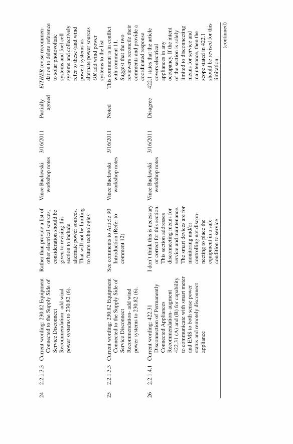
24
2.2.
1.3.
3 C
urre
nt w
ordi
ng: 2
30.8
2 E
quip
men
t C
onne
cted
to th
e Su
pply
Sid
e of
Se
rvic
e D
isco
nnec
t R
ecom
men
datio
n- a
dd w
ind
pow
er s
yste
ms
to 2
30.8
2 (6
).
Rat
her
than
pro
vide
a li
st o
f ot
her
elec
tric
al s
ourc
es,
cons
ider
atio
n sh
ould
be
give
n to
rev
isin
g th
is
sect
ion
to in
clud
e al
tern
ate
pow
er s
ourc
es.
Tha
t will
not
be
limiti
ng
to f
utur
e te
chno
logi
es
Vin
ce B
acla
wsk
i w
orks
hop
note
s 3/
16/2
011
Part
ially
ag
reed
E
ITH
ER
rev
ise
reco
mm
en-
datio
n to
del
ete
refe
renc
e to
sol
ar p
hoto
volta
ic
syst
ems
and
fuel
cel
l sy
stem
s an
d co
llect
ivel
y re
fer
to th
ese
(and
win
d po
wer
) sy
stem
s as
al
tern
ate
pow
er s
ourc
es
OR
add
win
d po
wer
sy
stem
s to
the
list
25
2.2.
1.3.
3 C
urre
nt w
ordi
ng: 2
30.8
2 E
quip
men
t C
onne
cted
to th
e Su
pply
Sid
e of
Se
rvic
e D
isco
nnec
t R
ecom
men
datio
n- a
dd w
ind
pow
er s
yste
ms
to 2
30.8
2 (6
).
See
com
men
ts to
Art
icle
90
Intr
oduc
tion
(Ref
er to
co
mm
ent 1
2)
Vin
ce B
acla
wsk
i w
orks
hop
note
s 3/
16/2
011
Not
ed
Thi
s co
mm
ent i
s in
con
fl ict
w
ith c
omm
ent 1
1.
Sugg
est t
hat t
he tw
o re
view
ers
reco
ncile
thei
r co
mm
ents
and
pro
vide
a
coor
dina
ted
resp
onse
26
2.
2.1.
4.1
Cur
rent
wor
ding
: 422
.31
Dis
conn
ectio
n of
Per
man
ently
C
onne
cted
App
lianc
es
Rec
omm
enda
tion-
aug
men
t 42
2.31
(A
) an
d (B
) fo
r ca
pabi
lity
to c
omm
unic
ate
with
sm
art m
eter
an
d E
MS
to b
oth
sens
e po
wer
st
atus
and
rem
otel
y di
scon
nect
ap
plia
nce
I do
n’t t
hink
this
is n
eces
sary
or
cor
rect
for
this
sec
tion.
T
his
sect
ion
addr
esse
s di
scon
nect
ing
mea
ns f
or
serv
ice
and
mai
nten
ance
. T
he s
mar
t dev
ices
are
for
m
onito
ring
and
/or
cont
rolli
ng n
ot d
isco
n-ne
ctin
g to
pla
ce th
e eq
uipm
ent i
n a
safe
co
nditi
on to
ser
vice
Vin
ce B
acla
wsk
i w
orks
hop
note
s 3/
16/2
011
Dis
agre
e 42
2.1
stat
es th
at th
e ar
ticle
co
vers
ele
ctri
cal
appl
ianc
es in
any
oc
cupa
ncy.
If
the
inte
nt
of th
e se
ctio
n is
sol
ely
limite
d to
dis
conn
ectin
g m
eans
for
ser
vice
and
m
aint
enan
ce, t
hen
the
scop
e st
ated
in 4
22.1
sh
ould
be
revi
sed
for
this
lim
itatio
n
(con
tinue
d)
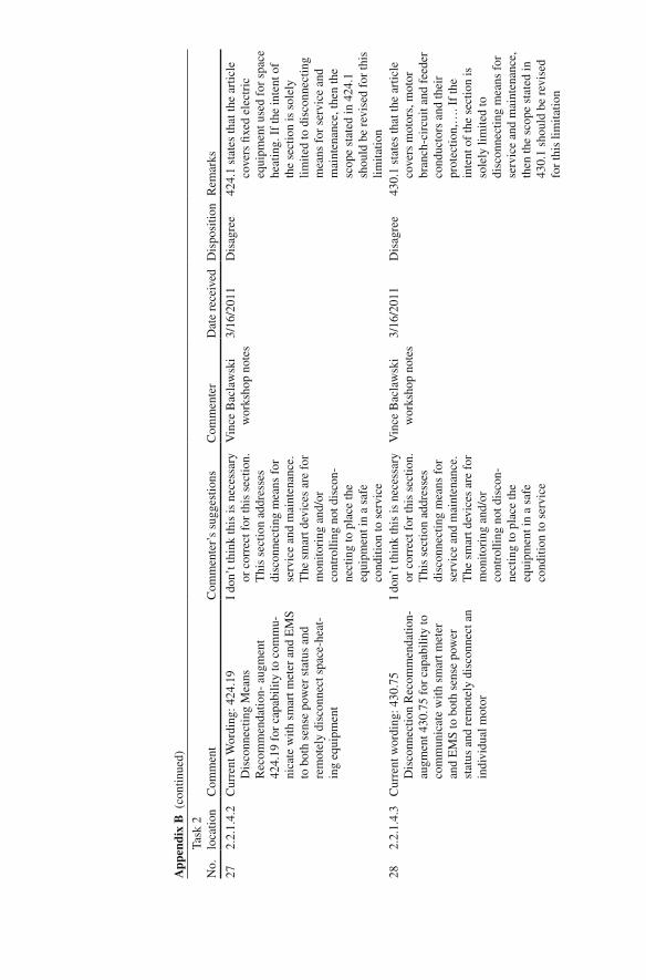
27
2.2.
1.4.
2 C
urre
nt W
ordi
ng: 4
24.1
9 D
isco
nnec
ting
Mea
ns
Rec
omm
enda
tion-
aug
men
t 42
4.19
for
cap
abili
ty to
com
mu-
nica
te w
ith s
mar
t met
er a
nd E
MS
to b
oth
sens
e po
wer
sta
tus
and
rem
otel
y di
scon
nect
spa
ce-h
eat-
ing
equi
pmen
t
I do
n’t t
hink
this
is n
eces
sary
or
cor
rect
for
this
sec
tion.
T
his
sect
ion
addr
esse
s di
scon
nect
ing
mea
ns f
or
serv
ice
and
mai
nten
ance
. T
he s
mar
t dev
ices
are
for
m
onito
ring
and
/or
cont
rolli
ng n
ot d
isco
n-ne
ctin
g to
pla
ce th
e eq
uipm
ent i
n a
safe
co
nditi
on to
ser
vice
Vin
ce B
acla
wsk
i w
orks
hop
note
s 3/
16/2
011
Dis
agre
e 42
4.1
stat
es th
at th
e ar
ticle
co
vers
fi xe
d el
ectr
ic
equi
pmen
t use
d fo
r sp
ace
heat
ing.
If
the
inte
nt o
f th
e se
ctio
n is
sol
ely
limite
d to
dis
conn
ectin
g m
eans
for
ser
vice
and
m
aint
enan
ce, t
hen
the
scop
e st
ated
in 4
24.1
sh
ould
be
revi
sed
for
this
lim
itatio
n 28
2.
2.1.
4.3
Cur
rent
wor
ding
: 430
.75
Dis
conn
ectio
n R
ecom
men
datio
n-
augm
ent 4
30.7
5 fo
r ca
pabi
lity
to
com
mun
icat
e w
ith s
mar
t met
er
and
EM
S to
bot
h se
nse
pow
er
stat
us a
nd r
emot
ely
disc
onne
ct a
n in
divi
dual
mot
or
I do
n’t t
hink
this
is n
eces
sary
or
cor
rect
for
this
sec
tion.
T
his
sect
ion
addr
esse
s di
scon
nect
ing
mea
ns f
or
serv
ice
and
mai
nten
ance
. T
he s
mar
t dev
ices
are
for
m
onito
ring
and
/or
cont
rolli
ng n
ot d
isco
n-ne
ctin
g to
pla
ce th
e eq
uipm
ent i
n a
safe
co
nditi
on to
ser
vice
Vin
ce B
acla
wsk
i w
orks
hop
note
s 3/
16/2
011
Dis
agre
e 43
0.1
stat
es th
at th
e ar
ticle
co
vers
mot
ors,
mot
or
bran
ch-c
ircu
it an
d fe
eder
co
nduc
tors
and
thei
r pr
otec
tion,
…. I
f th
e in
tent
of
the
sect
ion
is
sole
ly li
mite
d to
di
scon
nect
ing
mea
ns f
or
serv
ice
and
mai
nten
ance
, th
en th
e sc
ope
stat
ed in
43
0.1
shou
ld b
e re
vise
d fo
r th
is li
mita
tion
App
endi
x B
(co
ntin
ued)
No.
Task
2
loca
tion
Com
men
tC
omm
ente
r’s
sugg
estio
nsC
omm
ente
rD
ate
rece
ived
Dis
posi
tion
Rem
arks

29
2.2.
1.4.
4 C
urre
nt w
ordi
ng: 4
40.1
1 D
isco
nnec
ting
Mea
ns, G
ener
al
Rec
omm
enda
tion-
aug
men
t 44
0.11
for
cap
abili
ty to
com
mu-
nica
te w
ith s
mar
t met
er a
nd E
MS
to b
oth
sens
e po
wer
sta
tus
and
rem
otel
y di
scon
nect
AC
/R
efri
gera
tion
equi
pmen
t.
I do
n’t t
hink
this
is n
eces
sary
or
cor
rect
for
this
sec
tion.
T
his
sect
ion
addr
esse
s di
scon
nect
ing
mea
ns f
or
serv
ice
and
mai
nten
ance
. T
he s
mar
t dev
ices
are
for
m
onito
ring
and
/or
cont
rolli
ng n
ot d
isco
n-ne
ctin
g to
pla
ce th
e eq
uipm
ent i
n a
safe
co
nditi
on to
ser
vice
Vin
ce B
acla
wsk
i w
orks
hop
note
s 3/
16/2
011
Dis
agre
e 44
0.11
sta
tes
that
the
prov
isio
ns o
f Pa
rt I
I ar
e in
tend
ed to
req
uire
di
scon
nect
ing
mea
ns
capa
ble
of d
isco
nnec
ting
air-
cond
ition
ing
and
refr
iger
atin
g eq
uipm
ent,
…If
the
inte
nt o
f th
e se
ctio
n is
sol
ely
limite
d to
dis
conn
ectin
g m
eans
fo
r se
rvic
e an
d m
aint
e-na
nce,
then
the
scop
e st
ated
in 4
40.1
1 sh
ould
be
rev
ised
for
this
lim
itatio
n 30
2.
2.1.
4.5
Cur
rent
wor
ding
: 445
.18
Dis
conn
ectin
g M
eans
Req
uire
d fo
r G
ener
ator
s R
ecom
men
datio
n-
augm
ent 4
45.1
8 fo
r ca
pabi
lity
to
com
mun
icat
e w
ith s
mar
t met
er
and
EM
S to
bot
h se
nse
pow
er
stat
us a
nd r
emot
ely
star
t/sto
p on
-site
gen
erat
ors.
I do
n’t t
hink
this
is n
eces
sary
or
cor
rect
for
this
sec
tion.
T
his
sect
ion
addr
esse
s di
scon
nect
ing
mea
ns f
or
serv
ice
and
mai
nten
ance
. T
he s
mar
t dev
ices
are
for
m
onito
ring
and
/or
cont
rolli
ng n
ot d
isco
n-ne
ctin
g to
pla
ce th
e eq
uipm
ent i
n a
safe
co
nditi
on to
ser
vice
Vin
ce B
acla
wsk
i w
orks
hop
note
s 3/
16/2
011
Dis
agre
e 44
5.1
stat
es th
at th
e ar
ticle
co
ntai
ns in
stal
latio
n an
d ot
her
requ
irem
ents
for
ge
nera
tors
. If
the
inte
nt
of th
e se
ctio
n is
sol
ely
limite
d to
dis
conn
ectin
g m
eans
for
ser
vice
and
m
aint
enan
ce, t
hen
the
scop
e st
ated
in 4
45.1
sh
ould
be
revi
sed
for
this
lim
itatio
n
(con
tinue
d)

31
2.2.
1.4.
6 C
urre
nt w
ordi
ng: R
ecom
men
datio
n-
augm
ent 4
80.5
for
cap
abili
ty to
co
mm
unic
ate
with
sm
art m
eter
an
d E
MS
to b
oth
sens
e po
wer
st
atus
and
rem
otel
y ch
arge
/di
scha
rge
batte
ries
.
Mos
t of
thes
e re
com
men
da-
tions
to p
rovi
de r
emot
e co
ntro
l of
cert
ain
syst
ems/
appl
ianc
es m
ake
sens
e an
d ar
e no
t ge
nera
lly c
ritic
al.
How
ever
, the
re a
re m
any
stor
age
batte
ry s
yste
ms
inst
alle
d th
at a
re c
ritic
al
for
cont
inui
ty o
f es
sent
ial
serv
ices
or
syst
ems,
and
it
may
be
argu
ed th
at
cont
rolli
ng th
e ch
arge
of
thos
e ba
ttery
sys
tem
s m
ight
com
prom
ise
the
inte
nt o
f th
e sy
stem
if n
ot
fully
cha
rged
Vin
ce B
acla
wsk
i w
orks
hop
note
s 3/
16/2
011
Agr
ee
Rev
ised
rec
omm
enda
tion-
au
gmen
t 480
.5 f
or
capa
bilit
y to
com
mun
i-ca
te w
ith s
mar
t met
er a
nd
EM
S to
bot
h se
nse
pow
er
stat
us a
nd r
emot
ely
char
ge o
r di
scha
rge
batte
ries
, unl
ess
the
stor
age
batte
ry s
yste
ms
are
criti
cal f
or c
ontin
uity
of
ess
entia
l ser
vice
s or
sy
stem
s
32
2.2.
1.4.
6 C
urre
nt w
ordi
ng: 4
80.5
D
isco
nnec
ting
Mea
ns
Rec
omm
enda
tion-
aug
men
t 480
.5
for
capa
bilit
y to
com
mun
icat
e w
ith s
mar
t met
er a
nd E
MS
to
both
sen
se p
ower
sta
tus
and
rem
otel
y ch
arge
/dis
char
ge
batte
ries
.
I do
n’t t
hink
this
is n
eces
sary
or
cor
rect
for
this
sec
tion.
T
his
sect
ion
addr
esse
s di
scon
nect
ing
mea
ns f
or
serv
ice
and
mai
nten
ance
. T
he s
mar
t dev
ices
are
for
m
onito
ring
and
/or
cont
rolli
ng n
ot d
isco
n-ne
ctin
g to
pla
ce th
e eq
uipm
ent i
n a
safe
co
nditi
on to
ser
vice
Vin
ce B
acla
wsk
i w
orks
hop
note
s 3/
16/2
011
Dis
agre
e 48
0.1
stat
es th
at th
e pr
ovis
ions
of
this
art
icle
sh
all a
pply
to a
ll st
atio
nary
inst
alla
tions
of
stor
age
batte
ries
. If
the
inte
nt o
f th
e se
ctio
n is
so
lely
lim
ited
to
disc
onne
ctin
g m
eans
for
se
rvic
e an
d m
aint
enan
ce,
then
the
scop
e st
ated
in
480.
1 sh
ould
be
revi
sed
for
this
lim
itatio
n
App
endi
x B
(co
ntin
ued)
No.
Task
2
loca
tion
Com
men
tC
omm
ente
r’s
sugg
estio
nsC
omm
ente
rD
ate
rece
ived
Dis
posi
tion
Rem
arks

33
2.2.
1.5.
1 C
urre
nt w
ordi
ng: 5
17.3
1 Sc
ope
- E
mer
genc
y Sy
stem
s R
ecom
men
datio
n- a
men
d se
ctio
n to
ens
ure
that
bot
h lif
e sa
fety
and
cr
itica
l bra
nche
s re
mai
n po
wer
ed
duri
ng lo
ad s
hedd
ing.
Thi
s sh
ould
n’t b
e ne
cess
ary
as th
e re
quir
emen
ts o
f C
haps
. 5, 6
, and
7
over
ride
Cha
ps. 1
–4.
Art
icle
517
(an
d ot
hers
) w
ill r
equi
re th
e lif
e-sa
fety
re
quir
emen
ts r
egar
dles
s of
the
reco
gniti
on o
r us
e of
sm
art g
rid
load
sh
eddi
ng f
or g
ener
al u
ses
Vin
ce B
acla
wsk
i w
orks
hop
note
s 3/
16/2
011
Cla
rify
R
eque
st c
omm
ente
r re
asse
ss
if th
e re
com
men
datio
n sh
ould
rem
ain
or b
e w
ithdr
awn
34
2.2.
1 N
ote
that
the
chan
ges
are
to s
ectio
ns,
not a
rtic
les
Wor
ksho
p gr
oup
com
men
ts
3/29
/201
1 A
gree
d R
efer
ence
d ch
ange
d
35
Gen
eral
C
onsi
der
a ju
sti fi
catio
n se
ctio
n W
orks
hop
Gro
up
Com
men
ts
3/29
/201
1 C
lari
fi ed
The
sub
stan
tiatio
n as
soci
ated
w
ith e
ach
artic
le
refe
renc
e is
inte
nded
to
func
tion
as th
e ju
sti fi
catio
n 36
G
ener
al
Thi
s sh
ould
als
o ap
ply
to m
anuf
ac-
ture
d ho
usin
g W
orks
hop
grou
p co
mm
ents
3/
29/2
011
Cla
rify
R
eque
st c
omm
ente
r id
entif
y sp
eci fi
c A
rtic
le 5
50
issu
es th
at s
houl
d be
ex
amin
ed
37
Tabl
e 2.1
Con
side
r ca
lling
thes
e “c
once
rns”
in
stea
d of
“su
gges
ted
revi
sion
s”
Wor
ksho
p gr
oup
com
men
ts
3/29
/201
1 A
gree
d R
efer
ence
cha
nged
38
2.2.
1.1.
1 C
urre
nt w
ordi
ng: R
evis
e (3
) to
rea
d “I
nsta
llatio
n of
con
duct
ors
and
equi
pmen
t tha
t con
nect
to th
e su
pply
sid
e of
ele
ctri
city
or
com
mun
icat
ion .
”
Don
’t u
se th
e w
ord
“sid
e”
Wor
ksho
p gr
oup
com
men
ts
3/29
/201
1 C
lari
fi ed
NFP
A 7
0 25
0.2
uses
the
term
“s
uppl
y si
de”.
Els
ewhe
re
it is
hyp
hena
ted
(250
.30
A 2
) “s
uppl
y-si
de”
39
2.2.
1.2.
1 So
me
of th
ese
de fi n
ition
s ha
ve
alre
ady
been
add
ed to
in th
e ne
w
addi
tion
Wor
ksho
p gr
oup
com
men
ts
3/29
/201
1 A
gree
d R
efer
ence
s to
sub
ject
s w
ith
dedi
cate
d ar
ticle
s re
mov
ed
(con
tinue
d)
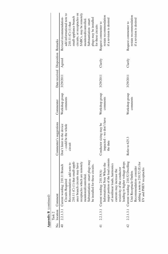
40
2.2.
1.3.
1 C
urre
nt w
ordi
ng: 2
10.1
1 B
ranc
h C
ircu
its R
equi
red
Rec
omm
enda
tion-
add
not
e to
21
0.11
(C
) (1
) th
at s
mal
l-ap
pli-
ance
bra
nch
circ
uits
may
hav
e re
cept
acle
s w
hich
are
rem
otel
y m
onito
red/
cont
rolle
d.
Subs
tant
iatio
n- s
mar
t plu
gs m
ay
be in
stal
led
for
thes
e ci
rcui
ts.
Don
’t li
mit
to th
e de
vice
–
coul
d be
the
who
le
circ
uit
Wor
ksho
p gr
oup
com
men
ts
3/29
/201
1 A
gree
d R
evis
ed r
ecom
men
datio
n-
add
info
rmat
iona
l not
e to
21
0.11
(C
) (1
) th
at
smal
l-ap
plia
nce
bran
ch
circ
uits
, or
rece
ptac
les
on
SAB
Cs,
may
be
rem
otel
y m
onito
red/
cont
rolle
d.
Subs
tant
iatio
n- s
mar
t pl
ugs
may
be
inst
alle
d fo
r th
ese
circ
uits
41
2.
2.1.
3.1
Cur
rent
wor
ding
: 210
.19(
A)
Info
rmat
iona
l Not
e W
here
the
maj
or p
ortio
n of
the
load
con
sist
s of
non
linea
r lo
ads,
har
mon
ics
curr
ents
may
incr
ease
the
resi
stiv
ity o
f th
e co
nduc
tor
lead
ing
to h
ighe
r vo
ltage
dro
ps
Con
duct
or s
izin
g m
ay b
e im
pact
ed –
we
don’
t hav
e th
e da
ta
Wor
ksho
p gr
oup
com
men
ts
3/29
/201
1 C
lari
fy
Req
uest
com
men
ter
to
rest
ate
reco
mm
enda
tion
if a
rev
isio
n is
des
ired
42
2.2.
1.3.
1 C
urre
nt w
ordi
ng: 2
10.5
2 D
wel
ling
Uni
t Rec
epta
cle
Out
lets
R
ecom
men
datio
n- c
onsi
der
addi
ng a
not
e to
210
.52
(E)
for
EV
and
PH
EV
rec
epta
cles
Ref
er to
625
.3
Wor
ksho
p gr
oup
com
men
ts
3/29
/201
1 C
lari
fy
Req
uest
com
men
ter
to
rest
ate
reco
mm
enda
tion
if a
rev
isio
n is
des
ired
App
endi
x B
(co
ntin
ued)
No.
Task
2
loca
tion
Com
men
tC
omm
ente
r’s
sugg
estio
nsC
omm
ente
rD
ate
rece
ived
Dis
posi
tion
Rem
arks
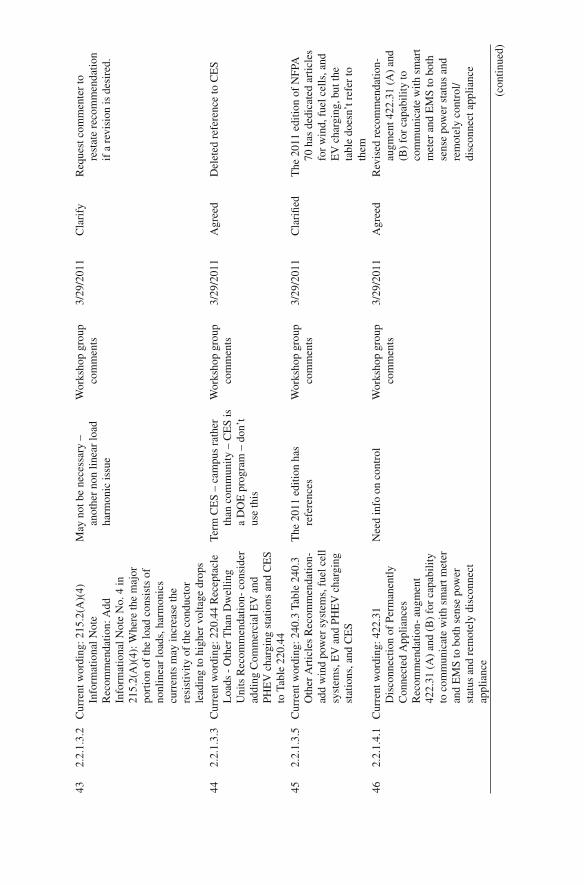
43
2.2.
1.3.
2 C
urre
nt w
ordi
ng: 2
15.2
(A)(
4)In
form
atio
nal N
ote
Rec
omm
enda
tion:
Add
In
form
atio
nal N
ote
No.
4 in
21
5.2(
A)(
4): W
here
the
maj
or
port
ion
of th
e lo
ad c
onsi
sts
of
nonl
inea
r lo
ads,
har
mon
ics
curr
ents
may
incr
ease
the
resi
stiv
ity o
f th
e co
nduc
tor
lead
ing
to h
ighe
r vo
ltage
dro
ps
May
not
be
nece
ssar
y –
anot
her
non
linea
r lo
ad
harm
onic
issu
e
Wor
ksho
p gr
oup
com
men
ts
3/29
/201
1 C
lari
fy
Req
uest
com
men
ter
to
rest
ate
reco
mm
enda
tion
if a
rev
isio
n is
des
ired
.
44
2.2.
1.3.
3 C
urre
nt w
ordi
ng: 2
20.4
4 R
ecep
tacl
e L
oads
- O
ther
Tha
n D
wel
ling
Uni
ts R
ecom
men
datio
n- c
onsi
der
addi
ng C
omm
erci
al E
V a
nd
PHE
V c
harg
ing
stat
ions
and
CE
S to
Tab
le 2
20.4
4
Term
CE
S –
cam
pus
rath
er
than
com
mun
ity –
CE
S is
a
DO
E p
rogr
am –
don
’t
use
this
Wor
ksho
p gr
oup
com
men
ts
3/29
/201
1 A
gree
d D
elet
ed r
efer
ence
to C
ES
45
2.2.
1.3.
5 C
urre
nt w
ordi
ng: 2
40.3
Tab
le 2
40.3
O
ther
Art
icle
s R
ecom
men
datio
n-
add
win
d po
wer
sys
tem
s, f
uel c
ell
syst
ems,
EV
and
PH
EV
cha
rgin
g st
atio
ns, a
nd C
ES
The
201
1 ed
ition
has
re
fere
nces
W
orks
hop
grou
p co
mm
ents
3/
29/2
011
Cla
ri fi e
d T
he 2
011
editi
on o
f N
FPA
70
has
ded
icat
ed a
rtic
les
for
win
d, f
uel c
ells
, and
E
V c
harg
ing,
but
the
tabl
e do
esn’
t ref
er to
th
em
46
2.2.
1.4.
1 C
urre
nt w
ordi
ng: 4
22.3
1 D
isco
nnec
tion
of P
erm
anen
tly
Con
nect
ed A
pplia
nces
R
ecom
men
datio
n- a
ugm
ent
422.
31 (
A)
and
(B)
for
capa
bilit
y to
com
mun
icat
e w
ith s
mar
t met
er
and
EM
S to
bot
h se
nse
pow
er
stat
us a
nd r
emot
ely
disc
onne
ct
appl
ianc
e
Nee
d in
fo o
n co
ntro
l W
orks
hop
grou
p co
mm
ents
3/
29/2
011
Agr
eed
Rev
ised
rec
omm
enda
tion-
au
gmen
t 422
.31
(A)
and
(B)
for
capa
bilit
y to
co
mm
unic
ate
with
sm
art
met
er a
nd E
MS
to b
oth
sens
e po
wer
sta
tus
and
rem
otel
y co
ntro
l/di
scon
nect
app
lianc
e
(con
tinue
d)

47
2.2.
1.7.
1 C
urre
nt w
ordi
ng: 7
00.4
Cap
acity
R
ecom
men
datio
n- a
men
d 70
0.4
(B)
to in
clud
e sa
fegu
ards
, suc
h as
a
diff
eren
t EM
S, a
gain
st th
e em
erge
ncy
syst
em b
eing
trea
ted
as a
reg
ular
sys
tem
for
the
purp
oses
of
load
she
ddin
g. A
lso
cons
ider
add
ing
pers
onne
l st
anda
rds
rega
rdin
g w
ho s
houl
d be
allo
wed
to d
eter
min
e w
hen
load
she
ddin
g is
app
ropr
iate
for
th
ese
syst
ems
Not
rea
lly p
erso
nnel
st
anda
rds
– it’
s ad
min
is-
trat
ive
cont
rol –
it’s
a 7
0E
issu
e
Wor
ksho
p gr
oup
Com
men
ts
3/29
/201
1 A
gree
d E
limin
ated
the
last
sen
tenc
e of
the
reco
mm
enda
tion.
E
limin
ated
add
ition
al
sim
ilar
refe
renc
es in
N
FPA
70
Cha
p. 7
48
De fi
nitio
ns f
or a
cron
yms,
con
sist
ent
voca
bula
ry w
ith N
FPA
and
oth
er
orga
niza
tions
Wor
ksho
p B
lue
Gro
up
com
men
ts
3/29
/201
1 A
gree
d R
eque
st c
omm
ente
r to
cite
sp
eci fi
c ar
eas
of
disa
gree
men
t 49
Fo
cus
on w
hat a
re th
e im
med
iate
im
pact
s ve
rsus
fut
uris
tic
Wor
ksho
p B
lue
Gro
up
com
men
ts
3/29
/201
1 C
lari
fy
Req
uest
com
men
ter
to
clar
ify
if a
rev
isio
n is
re
ques
ted
50
Nee
d an
FC
C f
ocus
W
orks
hop
Blu
e G
roup
C
omm
ents
3/29
/201
1 C
lari
fy
Req
uest
com
men
ter
to
clar
ify
if a
rev
isio
n is
re
ques
ted
51
Rep
ort f
orm
at –
link
issu
es to
cod
e pr
ovis
ions
– p
rior
itize
W
orks
hop
Blu
e G
roup
co
mm
ents
3/29
/201
1 A
gree
d Pr
iori
tizat
ion
will
be
cond
ucte
d as
par
t of
Task
4
52
2.3
Oth
er in
dust
ry s
tand
ards
that
sho
uld
be r
evie
wed
in a
dditi
on to
N
EM
A, I
EE
E, U
L, a
nd N
IST
PA
PS
CSA
, SA
E, I
EC
C, C
IEC
N
MX
, ISO
– w
e w
ant a
m
ore
glob
al fl
avor
Wor
ksho
p B
lue
Gro
up
com
men
ts
3/29
/201
1 A
gree
d R
evie
w o
f ad
ditio
nal
stan
dard
s is
des
irab
le,
how
ever
, thi
s is
out
side
th
e cu
rren
t sco
pe
App
endi
x B
(co
ntin
ued)
No.
Task
2
loca
tion
Com
men
tC
omm
ente
r’s
sugg
estio
nsC
omm
ente
rD
ate
rece
ived
Dis
posi
tion
Rem
arks
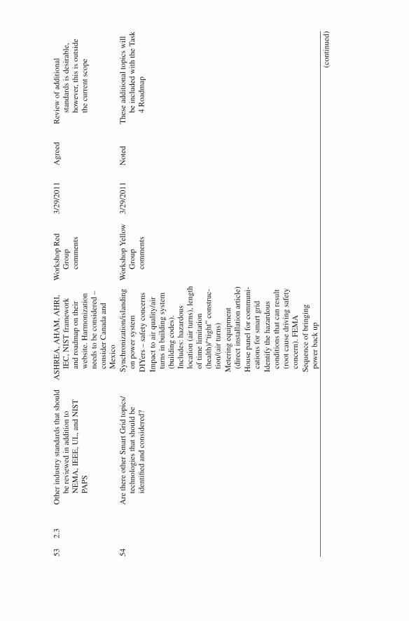
53
2.3
Oth
er in
dust
ry s
tand
ards
that
sho
uld
be r
evie
wed
in a
dditi
on to
N
EM
A, I
EE
E, U
L, a
nd N
IST
PA
PS
ASH
RE
A, A
HA
M, A
HR
I,
IEC
, NIS
T f
ram
ewor
k an
d ro
adm
ap o
n th
eir
web
site
. Har
mon
izat
ion
need
s to
be
cons
ider
ed –
co
nsid
er C
anad
a an
d M
exic
o
Wor
ksho
p R
ed
Gro
up
com
men
ts
3/29
/201
1 A
gree
d R
evie
w o
f ad
ditio
nal
stan
dard
s is
des
irab
le,
how
ever
, thi
s is
out
side
th
e cu
rren
t sco
pe
54
Are
ther
e ot
her
Smar
t Gri
d to
pics
/te
chno
logi
es th
at s
houl
d be
id
enti fi
ed a
nd c
onsi
dere
d?
Sy
nchr
oniz
atio
n/is
land
ing
on p
ower
sys
tem
W
orks
hop
Yel
low
G
roup
co
mm
ents
3/29
/201
1 N
oted
T
hese
add
ition
al to
pics
will
be
incl
uded
with
the
Task
4
Roa
dmap
DIY
ers
– sa
fety
con
cern
s
Impa
ct to
air
qua
lity/
air
turn
s in
bui
ldin
g sy
stem
(b
uild
ing
code
s).
Incl
udes
: haz
ardo
us
loca
tion
(air
turn
s), l
engt
h of
tim
e lim
itatio
n (h
ealth
)/“t
ight
” co
nstr
uc-
tion/
(air
turn
s)
M
eter
ing
equi
pmen
t (d
irec
t ins
talla
tion
artic
le)
H
ouse
pan
el f
or c
omm
uni-
catio
ns f
or s
mar
t gri
d
Iden
tify
the
haza
rdou
s co
nditi
ons
that
can
res
ult
(roo
t cau
se d
rivi
ng s
afet
y co
ncer
n). F
EM
A
Se
quen
ce o
f br
ingi
ng
pow
er b
ack
up
(con
tinue
d)
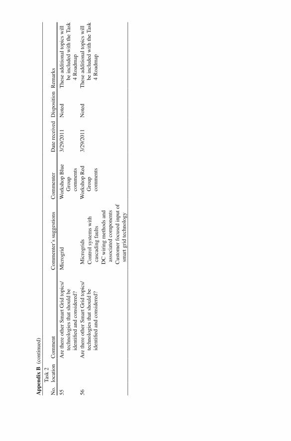
55
Are
ther
e ot
her
Smar
t Gri
d to
pics
/te
chno
logi
es th
at s
houl
d be
id
enti fi
ed a
nd c
onsi
dere
d?
Mic
rogr
id
Wor
ksho
p B
lue
Gro
up
com
men
ts
3/29
/201
1 N
oted
T
hese
add
ition
al to
pics
will
be
incl
uded
with
the
Task
4
Roa
dmap
56
A
re th
ere
othe
r Sm
art G
rid
topi
cs/
tech
nolo
gies
that
sho
uld
be
iden
ti fi ed
and
con
side
red?
M
icro
grid
s W
orks
hop
Red
G
roup
co
mm
ents
3/29
/201
1 N
oted
T
hese
add
ition
al to
pics
will
be
incl
uded
with
the
Task
4
Roa
dmap
Con
trol
sys
tem
s w
ith
casc
adin
g fa
ults
DC
wir
ing
met
hods
and
as
soci
ated
com
pone
nts
C
usto
mer
foc
used
inpu
t of
smar
t gri
d te
chno
logy
App
endi
x B
(co
ntin
ued)
No.
Task
2
loca
tion
Com
men
tC
omm
ente
r’s
sugg
estio
nsC
omm
ente
rD
ate
rece
ived
Dis
posi
tion
Rem
arks