smart professional surveillance system user’s manual · acs attendance node setup ... the system...
TRANSCRIPT

Smart Professional Surveillance System User’s Manual
Version 2.0.2

i
Table of Contents
CYBERSECURITY RECOMMENDATIONS ............................................................ VII
Cybersecurity Recommendations ..................................................................................................... vii
1. SMARTPSS OVERVIEW .................................................................................... 1
1.1 SmartPSS Overview ..................................................................................................................... 1
1.2 SmartPSS Interface ...................................................................................................................... 1
2. LOGIN ................................................................................................................. 4
2.1 Initialize Device ............................................................................................................................. 4
2.2 Login SmartPSS ........................................................................................................................... 6
2.3 Reset Password ............................................................................................................................ 8
3. DEVICES .......................................................................................................... 11
3.1 Add Device .................................................................................................................................. 11 Auto Search ......................................................................................................................... 11 Manually Add ....................................................................................................................... 12 Batch Import and Add Device .............................................................................................. 14
3.2 Modify Device Info ...................................................................................................................... 14
3.3 Modify IP ...................................................................................................................................... 15
3.4 Delete Device .............................................................................................................................. 16 Single Delete ....................................................................................................................... 16 Batch Delete ........................................................................................................................ 17
4. PREVIEW ......................................................................................................... 18
4.1 Introduction to Interface ............................................................................................................ 18
4.2 Live View ..................................................................................................................................... 19 Start Live .............................................................................................................................. 19 Live Operation ..................................................................................................................... 20 Adjust Monitor Window Number .......................................................................................... 22
4.3 E-Map ........................................................................................................................................... 24 New Map .............................................................................................................................. 24 Preview Map or Hot Zone .................................................................................................... 26

ii
4.4 Config IVS Channel .................................................................................................................... 27 Scene Config ....................................................................................................................... 28 General Behavior Analytics ................................................................................................. 29
4.4.2.1 Enable Behavior Analytics .......................................................................................... 30 4.4.2.2 Calibration ................................................................................................................... 30 4.4.2.3 Set Detection Zone ..................................................................................................... 31 4.4.2.4 IVS Rule ...................................................................................................................... 32 4.4.2.5 Parameters .................................................................................................................. 53
4.5 Smart Track Config (Fisheye+Dome) ....................................................................................... 54 Calibration Requirement ...................................................................................................... 54 Calibrate Camera ................................................................................................................. 55 Achieve Smart Track (Fisheye and Dome) .......................................................................... 58
4.6 Smart Track Config (Dome+Fixed) ........................................................................................... 59 Calibration Requirement ...................................................................................................... 59 Calibrate Camera ................................................................................................................. 60 Achieve Smart Track (Fixed and Dome) ............................................................................. 63
4.7 PTZ ............................................................................................................................................... 67 Preset ................................................................................................................................... 69 Tour ...................................................................................................................................... 69 Scan ..................................................................................................................................... 70 Pattern ................................................................................................................................. 71 Enable Windshield Wiper ..................................................................................................... 71
4.8 Fisheye View Mode..................................................................................................................... 71
4.9 Device Preview via NKB1000 Keyboard ................................................................................... 72
5. TOUR & TASK .................................................................................................. 74
5.1 Config Task Plan ........................................................................................................................ 74
5.2 Enable Task ................................................................................................................................. 78
6. PLAYBACK ...................................................................................................... 79
6.1 Playback ...................................................................................................................................... 79
6.2 Playback Device Record ............................................................................................................ 82
6.3 Export Device Record ................................................................................................................ 82
6.4 Playback Device Picture ............................................................................................................ 84
6.5 Export Device Picture ................................................................................................................ 85
6.6 Playback Local Record .............................................................................................................. 86

iii
6.7 Export Local Record .................................................................................................................. 87
6.8 Playback Local Picture .............................................................................................................. 88
7. LOG SEARCH .................................................................................................. 90
7.1 Search Client Log ....................................................................................................................... 90
7.2 Search Device Log ..................................................................................................................... 90
8. SYSTEM CONFIG ............................................................................................ 92
9. USER ................................................................................................................ 95
9.1 Role Info ...................................................................................................................................... 95
9.2 User .............................................................................................................................................. 96
10. DEVICE CONFIG .......................................................................................... 99
11. EVENT CONFIG .......................................................................................... 102
11.1 Event Type ............................................................................................................................ 102
11.2 Event Alarm Link Config ..................................................................................................... 105 Link Notice ......................................................................................................................... 105 Link Video .......................................................................................................................... 106 Link Alarm Output .............................................................................................................. 108 Arm Time ........................................................................................................................... 109
11.3 Event View ............................................................................................................................ 110
12. VIDEO WALL .............................................................................................. 111
12.1 Video Wall ............................................................................................................................. 111
12.2 Config Favorites ................................................................................................................... 113 Add Favorite....................................................................................................................... 113 Delete Favorite .................................................................................................................. 115 Delete Channel .................................................................................................................. 115 Change Favorite Name ...................................................................................................... 115
12.3 Set Video Wall and Output .................................................................................................. 116
12.4 Scheme Tour on Video Wall ................................................................................................ 118
12.5 Playback on Video Wall ....................................................................................................... 119

iv
13. PEOPLE COUNT ........................................................................................ 121
14. HEAT MAP .................................................................................................. 124
15. PC-NVR ....................................................................................................... 125
15.1 Disk Manager ........................................................................................................................ 125
15.2 Channel Management .......................................................................................................... 125
15.3 Set Record Plan .................................................................................................................... 126
15.4 Version Info .......................................................................................................................... 127
15.5 Modify Port ........................................................................................................................... 128
15.6 Modify Password .................................................................................................................. 129
16. VIDEO TALK ............................................................................................... 130
16.1 VTS Center ............................................................................................................................ 130
16.2 Monitor .................................................................................................................................. 130
16.3 Intercom ................................................................................................................................ 131
16.4 Announcement ..................................................................................................................... 135
16.5 Search ................................................................................................................................... 136
16.6 Issue Card ............................................................................................................................. 137
17. ACCESS ..................................................................................................... 141
17.1 Console ................................................................................................................................. 141 Organizations/Zones .......................................................................................................... 142
17.1.1.1 E-Map ........................................................................................................................ 142 17.1.1.2 Device Control ........................................................................................................... 142
List/View ............................................................................................................................. 145 Event .................................................................................................................................. 147
17.2 User Management ................................................................................................................ 148 Department Management .................................................................................................. 149 User Management ............................................................................................................. 150
17.2.2.1 Set Card Type ........................................................................................................... 150 17.2.2.2 Add User ................................................................................................................... 150
17.3 Permission Management ..................................................................................................... 156 Period Setup ...................................................................................................................... 156

v
Holiday Setup .................................................................................................................... 157 Door Group Right ............................................................................................................... 158 User Right .......................................................................................................................... 162 First Card Unlock ............................................................................................................... 162 Multi-door Lock .................................................................................................................. 163 Anti-pass Back ................................................................................................................... 166 Inter-door Lock ................................................................................................................... 167 Remote Verification ........................................................................................................... 167
17.4 Event Configuration ............................................................................................................. 168
17.5 Log ......................................................................................................................................... 171
18. ATTENDANCE ............................................................................................ 173
18.1 Console ................................................................................................................................. 173 ACS Attendance Node Setup ............................................................................................ 173 Extract Card Info ................................................................................................................ 174
18.2 User ....................................................................................................................................... 174 Department/User ............................................................................................................... 174 Right ................................................................................................................................... 174
18.2.2.1 Enable Attendance Right .......................................................................................... 175 18.2.2.2 Disable Attendance Right ......................................................................................... 177
18.3 Set Attendance ..................................................................................................................... 177 Set Attendance Timezone ................................................................................................. 177 Set Attendance Shift .......................................................................................................... 180 Set Holiday......................................................................................................................... 182
18.4 Shift ....................................................................................................................................... 183 General Shift ...................................................................................................................... 183 Temporary Shift ................................................................................................................. 186 Set Default Shift for New User ........................................................................................... 187
18.5 Report .................................................................................................................................... 188 Extract Attendance Info ..................................................................................................... 188 Attendance Statistics ......................................................................................................... 189 Exception Attendance Processing ..................................................................................... 190

vi
Welcome
Thank you for using our Smart Professional Surveillance System (SmartPSS)! This user’s manual is designed to be a reference tool for operation of your system. Here you can find detailed operation information about SmartPSS.

vii
Cybersecurity Recommendations
Cybersecurity Recommendations Mandatory actions to be taken towards cybersecurity 1. Change Passwords and Use Strong Passwords: The number one reason systems get “hacked” is due to having weak or default passwords. It is recommended to change default passwords immediately and choose a strong password whenever possible. A strong password should be made up of at least 8 characters and a combination of special characters, numbers, and upper and lower case letters. 2. Update Firmware As is standard procedure in the tech-industry, we recommend keeping NVR, DVR, and IP camera firmware up-to-date to ensure the system is current with the latest security patches and fixes. “Nice to have” recommendations to improve your network security 1. Change Passwords Regularly Regularly change the credentials to your devices to help ensure that only authorized users are able to access the system. 2. Change Default HTTP and TCP Ports: ● Change default HTTP and TCP ports for systems. These are the two ports used to communicate and to view video feeds remotely. ● These ports can be changed to any set of numbers between 1025-65535. Avoiding the default ports reduces the risk of outsiders being able to guess which ports you are using. 3. Enable HTTPS/SSL: Set up an SSL Certificate to enable HTTPS. This will encrypt all communication between your devices and recorder. 4. Enable IP Filter: Enabling your IP filter will prevent everyone, except those with specified IP addresses, from accessing the system. 5. Change ONVIF Password: On older IP Camera firmware, the ONVIF password does not change when you change the system’s credentials. You will need to either update the camera’s firmware to the latest revision or manually change the ONVIF password.

viii
6. Forward Only Ports You Need: ● Only forward the HTTP and TCP ports that you need to use. Do not forward a huge range of numbers to the device. Do not DMZ the device's IP address. ● You do not need to forward any ports for individual cameras if they are all connected to a recorder on site; just the NVR is needed. 7. Disable Auto-Login on SmartPSS: Those using SmartPSS to view their system and on a computer that is used by multiple people should disable auto-login. This adds a layer of security to prevent users without the appropriate credentials from accessing the system. 8. Use a Different Username and Password for SmartPSS: In the event that your social media, bank, email, etc. account is compromised, you would not want someone collecting those passwords and trying them out on your video surveillance system. Using a different username and password for your security system will make it more difficult for someone to guess their way into your system. 9. Limit Features of Guest Accounts: If your system is set up for multiple users, ensure that each user only has rights to features and functions they need to use to perform their job. 10. UPnP: ● UPnP will automatically try to forward ports in your router or modem. Normally this would be a good thing. However, if your system automatically forwards the ports and you leave the credentials defaulted, you may end up with unwanted visitors. ● If you manually forwarded the HTTP and TCP ports in your router/modem, this feature should be turned off regardless. Disabling UPnP is recommended when the function is not used in real applications. 11. SNMP: Disable SNMP if you are not using it. If you are using SNMP, you should do so only temporarily, for tracing and testing purposes only. 12. Multicast: Multicast is used to share video streams between two recorders. Currently there are no known issues involving Multicast, but if you are not using this feature, deactivation can enhance your network security. 13. Check the Log: If you suspect that someone has gained unauthorized access to your system, you can check the system log. The system log will show you which IP addresses were used to login to your system and what was accessed.
ix
14. Physically Lock Down the Device: Ideally, you want to prevent any unauthorized physical access to your system. The best way to achieve this is to install the recorder in a lockbox, locking server rack, or in a room that is behind a lock and key. 15. Connect IP Cameras to the PoE Ports on the Back of an NVR: Cameras connected to the PoE ports on the back of an NVR are isolated from the outside world and cannot be accessed directly. 16. Isolate NVR and IP Camera Network The network your NVR and IP camera resides on should not be the same network as your public computer network. This will prevent any visitors or unwanted guests from getting access to the same network the security system needs in order to function properly.

1
1. SmartPSS Overview
1.1 SmartPSS Overview SmartPSS is an abbreviation for Smart Professional Surveillance System. The software is to manage small quantity security surveillance devices. It releases with the device and does not support the products from other manufacturers. It has the following features: Software password reset. View real-time video of several camera channels. View the playback video files from various cameras. Support multiple scheduled arms to realize auto PC guard. Support e-map; you can clearly view and manage all device locations. Video wall preview. People count and heat map. Search and export log. Support config and management of A&C device. Support config and management of intercom device. Support config and management of time attendance. Support config and management of alarm controller.
1.2 SmartPSS Interface SmartPSS software interface includes 5 parts: function tab, system info, function list, shortcut, and help. See Figure 1-1.
Figure 1-1

2
No.
Name Note
1 Function tab In default status, it shows Device tab, New tab and . Click
, you can add new tab. If you open function in New tab, it enters corresponding function interface, and meantime tab name is updated to new function name.
2 Event and . Click icon to switch event alarm between mute and sound.
(example only), click icon to enter Event interface. 3 User
Click , select lock screen. Click , select switch user. Click , select help manual. Click , select about, to show software version and date. Click , select user wizard to show new function and
features.
4 System Management
Click , enter system config interface. It supports base, preview and playback, device manager and etc.
Click , show system CPU occupancy status and memory. If CPU occupancy is high, the icon will become red as warning.
5 Window Click , minimize window. Click maximize window. Click to restore window. Click exit.
6 System Time Current system time.
3
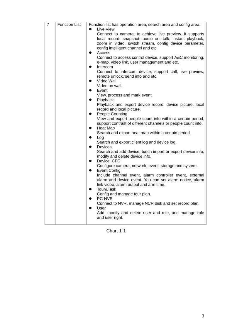
7 Function List Function list has operation area, search area and config area. Live View
Connect to camera, to achieve live preview. It supports local record, snapshot, audio on, talk, instant playback, zoom in video, switch stream, config device parameter, config intelligent channel and etc.
Access Connect to access control device, support A&C monitoring, e-map, video link, user management and etc.
Intercom Connect to intercom device, support call, live preview, remote unlock, send info and etc.
Video Wall Video on wall.
Event View, process and mark event.
Playback Playback and export device record, device picture, local record and local picture.
People Counting View and export people count info within a certain period, support contrast of different channels or people count info.
Heat Map Search and export heat map within a certain period.
Log Search and export client log and device log.
Devices Search and add device, batch import or export device info, modify and delete device info.
Device CFG Configure camera, network, event, storage and system.
Event Config Include channel event, alarm controller event, external alarm and device event. You can set alarm notice, alarm link video, alarm output and arm time.
Tour&Task Config and manage tour plan.
PC-NVR Connect to NVR, manage NCR disk and set record plan.
User Add, modify and delete user and role, and manage role and user right.
Chart 1-1

4
2. Login The chapter introduces how to login SmartPSS. For first time login, you shall initialize the device, set login password. If you forget the password, you can reset password via password reset function.
2.1 Initialize Device After SmartPSS installation is complete, you login it for the first time. Please follow system instructions to set admin login password and password security. This password set here is used to login system. Password security requires to answer security questions to reset password. Steps
Step 1. Double click . See Figure 2-1.
Figure 2-1
Step 2. Set password, see Figure 2-2.

5
Figure 2-2
Parameter Note Password Password can be 8~32 digits without space. It contains at least
two types of upper case, lower case, number and symbol (except “'”, “"”, “;”, “:”, or “&”).
Password Strength
It feedbacks password complexity. Red means password is not complex enough, and greens means password complexity is OK. Please set password according to its strength.
Confirm Password Match password set above.
Auto login after registration
Enable this option, so when registration complete, you will automatically log in the system.
Chart 2-1
Step 3. Click Next, see Figure 2-3.

6
Figure 2-3
Step 4. Select question and answer it. In case you forget password, you may reset password through these questions.
Step 5. Click Finish, save config.
2.2 Login SmartPSS After device initialization complete, enter username and login password.
Step 1. Double click , see Figure 2-4.

7
Figure 2-4
Step 2. Set parameter, see Chart 2-2.
Parameter Note
Enter username and password.
Remember password
Select it, system remember password and at next time of login, this password will be remembered.
Auto Login Select it, it auto remember password, and it will auto login at next time.
Forget password When you forget password, you can answer security question to reset password. See Ch 2.3.
Chart 2-2
Step 3. Click Login, see Figure 2-5. Note: If it is the first time login, the system will show wizard of user to introduce new function and features.

8
Figure 2-5
2.3 Reset Password When you forget password, please answer security question to reset password.
Step 1. Double click , see Figure 2-6.

9
Figure 2-6
Step 2. Click , see Figure 2-7.
Figure 2-7
Step 3. Answer security question, click Next, see Figure 2-8.

10
Figure 2-8
Step 4. Set password, see Chart 2-3. Parameter Note Password Password can be 8~32 digits without space. It contains at least
two types of upper case, lower case, number and symbol (except “'”, “"”, “;”, “:”, or “&”).
Password Strength
Feedback password strength. Red means weak password, and green means secure password.
Confirm Password Match password set above.
Chart 2-3
Step 5. Click OK.

11
3. Devices SmartPSS supports to add a single device or batch device (i.e. IPC, NVR) via auto search. You also can config and operate device.
3.1 Add Device SmartPSS supports to add device via multiple methods, please select method to add device according to device quantity, segment and etc.
Auto Search You must add device as batch and make them in the same segment, or if you do not know device IP, you can uses this method to add device when you only know device segment. Step 1. In Devices, click Search. Step 2. Set device segment and click Auto Search. See Figure 3-1. Note: Click Refresh, to refresh searched device. Check device IP you want to modify, click Modify IP to change IP. See Ch 3.3.
Figure 3-1
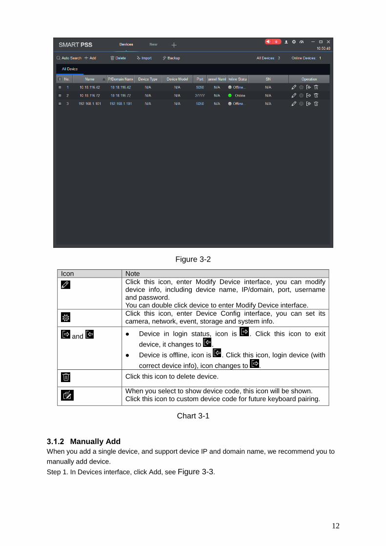
Step 3. Check device you want to add, click Add. Step 4. Click OK. Login box pops up. Step 5. Enter device username and password. Click OK. System shows device list added. See
Figure 3-2. After device is added, it stays at auto search page, you can continue to add device or click
Cancel to exit. After device is added, SmartPSS auto logins device. Login is successful, then online status
changes to “online”, otherwise it is “offline”.
12
Figure 3-2
Icon Note
Click this icon, enter Modify Device interface, you can modify device info, including device name, IP/domain, port, username and password. You can double click device to enter Modify Device interface.
Click this icon, enter Device Config interface, you can set its camera, network, event, storage and system info.
and Device in login status, icon is . Click this icon to exit device, it changes to .
Device is offline, icon is . Click this icon, login device (with correct device info), icon changes to .
Click this icon to delete device.
When you select to show device code, this icon will be shown. Click this icon to custom device code for future keyboard pairing.
Chart 3-1
Manually Add
When you add a single device, and support device IP and domain name, we recommend you to manually add device. Step 1. In Devices interface, click Add, see Figure 3-3.

13
Figure 3-3
Step 2. Set device parameter, see the following chart.
Item Function
Device name Please input a device name here.
Method to add By IP/domain and SN.
IP/Domain name
Device IP address or domain name. Note: You can add device of IPV6 address.
SN Device SN. Note: For P2P device only.
Port Device IP port. It is 37777 by default.
Group Name You can choose one group.
User name The user name you login the device.
Password The password you login the device.
Chart 3-2
Step 3. Click Add, complete adding of device.
14
Note: If you continue to add device, then click Save and Continue to add device and save the
manually added device. If you cancel adding, then click Cancel to exit. After device is added, SmartPSS auto logins the device. When it successfully logs in,
the device status becomes “online”, otherwise it is “offline”.
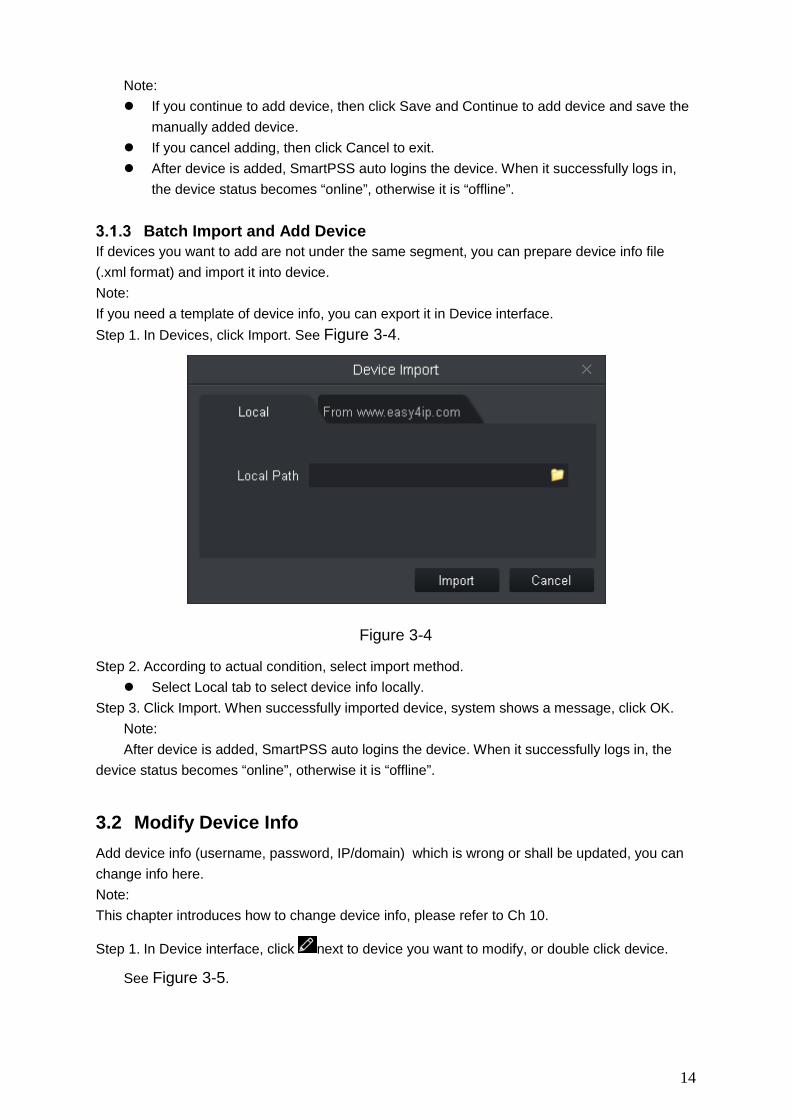
Batch Import and Add Device If devices you want to add are not under the same segment, you can prepare device info file (.xml format) and import it into device. Note: If you need a template of device info, you can export it in Device interface. Step 1. In Devices, click Import. See Figure 3-4.
Figure 3-4
Step 2. According to actual condition, select import method. Select Local tab to select device info locally.
Step 3. Click Import. When successfully imported device, system shows a message, click OK. Note: After device is added, SmartPSS auto logins the device. When it successfully logs in, the
device status becomes “online”, otherwise it is “offline”.
3.2 Modify Device Info Add device info (username, password, IP/domain) which is wrong or shall be updated, you can change info here. Note: This chapter introduces how to change device info, please refer to Ch 10.
Step 1. In Device interface, click next to device you want to modify, or double click device.
See Figure 3-5.

15
Figure 3-5
Step 2. Change device info, refer to Chart 3-2. Step 3. Click Save.
3.3 Modify IP Step 1. In Devices interface, click Auto Search. Step 2. Set device segment and click Search. See Figure 3-6.
Figure 3-6

16
Step 3. Check device you want to modify IP, click Modify IP. System pops up modify device IP box.
Step 4. Enter device IP info. Click OK. When you check a single device, system pops u p Modify IP box, see Figure 3-7.
Figure 3-7
When select more then one device, system pops up Batch Modify IP box, see Figure 3-8.
Figure 3-8
Step 5. Set device new IP start IP, subnet mask and gateway. Step 6. Click Save.
3.4 Delete Device If device added is no longer managed, please delete the device. You can delete one by one or by batch.
Single Delete
Step 1. In Device interface, click next to device you want to delete, see Figure 3-9.

17
Figure 3-9
Step 2. According to actual condition, check select “at the same time delete the delete snapshot and record” or not.
Step 3. Click OK.
Batch Delete Step 1. In Device interface, select device to delete. Step 2. Click Delete. See Figure 3-9.’ Step 3. According to actual condition, check select “at the same time delete the delete snapshot
and record” or not. Step 4. Click OK.
18
4. Preview After you add device on SmartPSS, you can enter Live View interface to preview. You also can set e-map and etc.
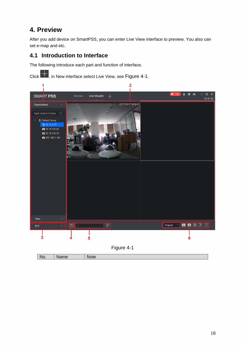
4.1 Introduction to Interface The following introduce each part and function of interface.
Click , in New interface select Live View, see Figure 4-1.
Figure 4-1
No. Name Note

19
No. Name Note 1
Device list
You can switch streams, create device groups, create new maps, update channel information, modify channel names, log off, and log in to devices. When the Default Device Tree is set to Device Tree (by
device), the device tree displays the grouping and channels for the device.
When the Default Device Tree is set to Area Tree (by channel), the device tree displays the zones and channels.
Here makes organization tree as an example. Area tree is same with organization tree. Device list supports to manage device (rename and delete group), switch stream, create map, enter device config, master-slave config, intelligent default and etc. Steps: Right click in space area, you can create group, same level
with default group. Right click to create group (create group under selected
group), rename group, select stream (apply to all channels in group), create map.
Right click one channel (device is online), and you can switch stream, enable alarm output, update channel info, enter device config, intelligent default, master-slave config interface, log out.
Right click channel (device is offline), log in device. 2 Preview
Window Browse this area, window can be split into various modes. You can snapshot, record during preview. It supports tour, talk, IVS overlay and etc., refer to Ch 4.2.
3
PTZ
For motorized zoom devices, focus, autofocus, or focus can be reset.
For PTZ setting, you can simulate the mouse, open or close PTZ menu, adjust PTZ speed, direction, zoom, focus and iris.
Click More Features to set Preset, Tour, Horizontal Rotation, Scan, Track, and Accessibility. See Ch 4.7.
4 Save View When there is many device connected, and you often preview more than once window at the same time, you can save preview as view of multiple devices, so when you enable this view in the future, it will auto open device preview saved.
Saved views are shown below view tab under device list, and can be added to tour plan and the same time.
5 Tour When tour plan exists, you can select tour quickly here.
6 Aspect Ratio and Window Split
adjust adpest ratio adjust split
Chart 4-1
4.2 Live View You can live view video, local record, snapshot, enable audio, talk, instant playback, zoom in video, switch stream, config device parameter, config intelligent channel, config master-slave track, update channel info and etc.
Start Live

20
You can preview via: Select preview window, double click to preview in device list. Drag device you want to preview into window. See Figure 4-2.
Figure 4-2
Live Operation
No. Task Note Operation
1 Open local record Save record to local
Select open video window which is ON, and click or right click to select Start Record.
Note: You can modify the saved path in System Configuration> File Settings .
2 Snapshot Manually snapshot
Select open video window which is ON, and click or right-click to select Snapshot, snapshot
a single picture. Note:
You can change the path where the image is saved in System Configuration> File Settings .
3 Triple Snapshot Snapshot three pictures at once
Select the preview video window, right click Triple Snapshot, the system continuously snapshot three pictures.
4 Start audio Start audio to get audio message sent to device
Select open video window which is ON, and click or right-click to select Start Audio.
5 Talk Talk to connected device Select open video window which is ON, and click or right-click to select Start Talk, you can talk between the client and the device.

21
No. Task Note Operation
6 Turn on the remote intercom
When you preview the channel under the storage device, and the device supports remote channel intercom, select the video window with preview opened, right-click to select Turn on the remote intercom, the remote channel on the client and the storage device can be speak.
Select open preview window, right click to select remote intercom.
7 Start instant playback
Playback record 1-60 min prior of current channel
Select open video window which is ON, and click or right-click to select Start Instant Playback .
8 Zoom in Select area to zoom in Select open video window which is ON, and click .
9 Close window N/A Select open video window which is ON, and
click or right click to select Close Window .
10 Close all windows N/A Select the video window, right-click to select
Close All Windows .
11 Playback Playback record video. Select the preview video window, right-click Playback to enter the Playback interface. See Ch 6.
12 Fisheye installation
For fisheye device only.
Fisheye installation mode
includes
(Ceiling), (Wall mount)
and (GND).
Select the video window with preview ON, right click on Fisheye Installation Mode and select the installation mode according to the actual installation of the device.
13 Fisheye view mode
For fisheye device only.
The view mode is different depending on the installation mode of the fisheye. See Ch 4.8.
Select the preview video window, right-click the Fisheye view mode, according to the actual situation to select the desired view mode.
14 Split screen tracking
Split screen tracking includes the normal mode, 1 +3 mode and 1 +5 mode three modes.
• Normal mode: Original image. • 1 + 3 mode: the original image and 3 sub-window, the original image can be adjusted 3 sub-window position. • 1 + 5 mode: the original image and 5 sub-window, the original image can be adjusted 5 sub-window position.
Select enabled preview window, right click split screen tracking, and select split.

22
No. Task Note Operation
15 Adjust
It is used to adjust the preview effect of the video screen on the client and does not change the actual image parameters of the device.
You can adjust the brightness, contrast, saturation and hue of the video screen.
1. Select open preview window, right click select image adjust.
2. Adjust image, click exit.
16 Smart overlay
Make intelligent rules or intelligent object box displayed in the video screen.
Select the video window with the preview turned on, right-click on the Intelligent overlay> Intelligent rule or Intelligent object box.
17 Set video scale Adjust aspect ratio of video.
Select the video window, right-click to select Window Scale, select the video screen display ratio.
18 Switch play strategy
Play strategy includes balance, real-time and fluency.
Select enabled video window, right click window and select play strategy.
19 Switch stream Support main stream, sub stream1 and sub stream 2.
Select enabled video window, right click stream type.
Chart 4-2
Adjust Monitor Window Number
Click , to adjust window number. The first three icons are commonly used for favorites, and the fourth window is custom window plus the fifth window is full screen. Favorites common windows
Click , in standard interface, you can select window split number. You may add number
of split up to 3 favorites. When you see a start marked at upper right corner, it means favorite is successfully added. See Figure 4-3.
Figure 4-3
23
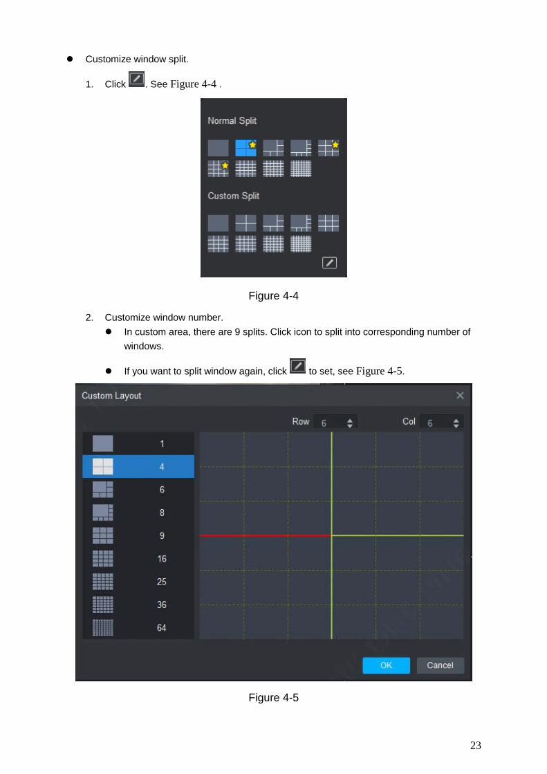
Customize window split.
1. Click . See Figure 4-4 .
Figure 4-4
2. Customize window number. In custom area, there are 9 splits. Click icon to split into corresponding number of
windows.
If you want to split window again, click to set, see Figure 4-5.
Figure 4-5

24
4.3 E-Map Via E-map you can straightly known the location of video channel or alarm channel and live preview.
New Map Step 1. Right click group in Organization Tree, select New Map. See Figure 4-6.
Figure 4-6
Step 2. Set map name, select path of picture. Step 3. Click Save. See Figure 4-7.
Figure 4-7
Note:
Click , create new hot zone on map.
Click , modify map name or replace map.
25
Click to adjust opacity.
At the lower right corner, you can see aerial view of map. Click , to close aerial view and
click to open aerial view.
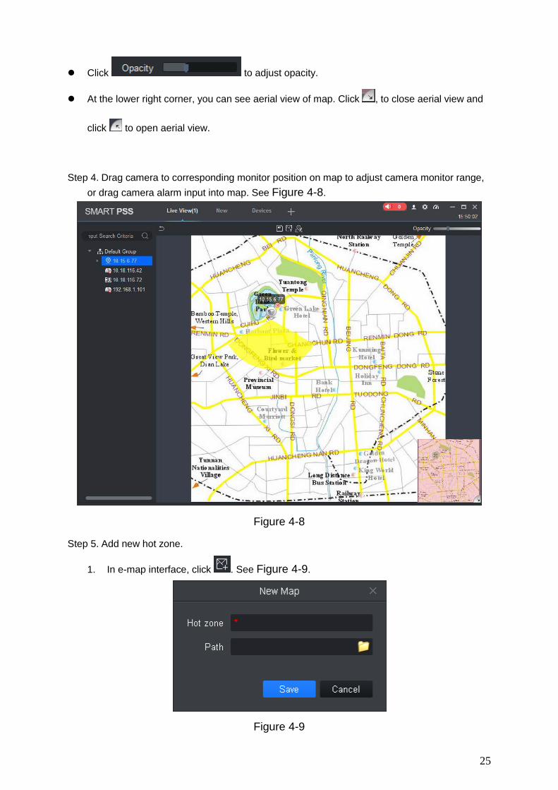
Step 4. Drag camera to corresponding monitor position on map to adjust camera monitor range,
or drag camera alarm input into map. See Figure 4-8.
Figure 4-8
Step 5. Add new hot zone.
1. In e-map interface, click . See Figure 4-9.
Figure 4-9

26
2. Set map name, select picture path. Click Save. 3. Double click hot zone, map switch to hot zone map, see Figure 4-10.
Figure 4-10
Note: On map, click picture window at the lower-left corner, you can return to map or previous level of hot zone.
4. Drag device in list to map, and adjust camera monitoring range.
Step 6. Click to save map. After config is complete, it shows created map and hot zone in it,
see Figure 4-11.
Figure 4-11
Preview Map or Hot Zone It supports to add camera on map or hot zone, and here uses hot zone as an example. Step 1. Open Live interface, in device list double click heat map or drag heat map into preview
window.

27
Step 2. On map click camera or place mouse on camera for a few seconds, in the pop-up window you can view live preview.
Note: In hot zone preview window, click , to return to map preview. If current preview is map, double click hot zone mark on it to enter hot zone. Click hot zone preview window, right click and select Open All Channels, at bottom
of preview window it shows live of all devices. Right click Video Wall, and in pop-up window it shows live of all devices.
4.4 Config IVS Channel IVS includes general behavior analytics, face recognition, people count, heat map and etc., different devices support different IVS plans, which subject to actual interface. In Live View interface, right click device in list, select IVS channel cfg, see Figure 4-12. Note: IVS analytics only detects IVS analytics capacity of connected device. Speed dome or PTZ device support scene config and preset selection, IPC do not support
scene config. Set IVS analytics refer to continuous setup in this chapter.
If you need a static scene, you can click to stop video; click to continue playing.

28
Figure 4-12[A1]
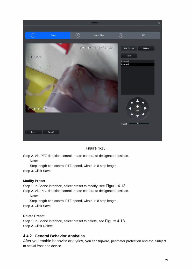
Scene Config For example to device to add is speed dome or PTZ device, then it supports to set preset in scene config interface, and you can set different plans for preset. Add Preset Step 1. In Scene interface, click Add Scene, see Figure 4-13.
29
Figure 4-13
Step 2. Via PTZ direction control, rotate camera to designated position. Note: Step length can control PTZ speed, within 1~8 step length.
Step 3. Click Save. Modify Preset Step 1. In Scene interface, select preset to modify, see Figure 4-13. Step 2. Via PTZ direction control, rotate camera to designated position.
Note: Step length can control PTZ speed, within 1~8 step length.
Step 3. Click Save. Delete Preset Step 1. In Scene interface, select preset to delete, see Figure 4-13. Step 2. Click Delete.
General Behavior Analytics After you enable behavior analytics, you can tripwire, perimeter protection and etc. Subject to actual front-end device.

30
4.4.2.1 Enable Behavior Analytics Step 1. In Scene interface, when preset setup is complete, click Next. See Figure 4-14.
Figure 4-14
Step 2. Select scene.
Step 3. Click and select IVS plan.
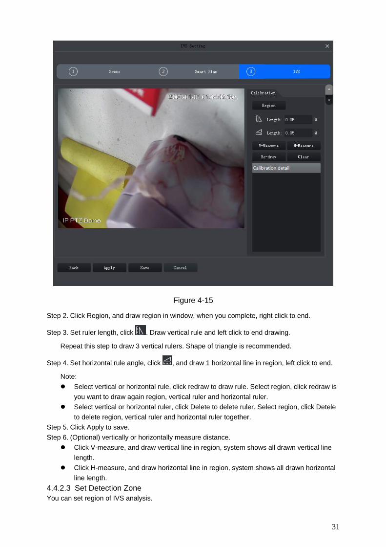
4.4.2.2 Calibration According to user marked 1 horizontal line and 3 vertical lines, and corresponding actual distance, it can estimate internal parameter and external parameter in order to confirm relationship between gotten 2D image and 3D actual object. Step 1. In Smart Plan interface select plan and click Next or config, see Figure 4-15.
31
Figure 4-15
Step 2. Click Region, and draw region in window, when you complete, right click to end.
Step 3. Set ruler length, click . Draw vertical rule and left click to end drawing.
Repeat this step to draw 3 vertical rulers. Shape of triangle is recommended.
Step 4. Set horizontal rule angle, click , and draw 1 horizontal line in region, left click to end.
Note: Select vertical or horizontal rule, click redraw to draw rule. Select region, click redraw is
you want to draw again region, vertical ruler and horizontal ruler. Select vertical or horizontal ruler, click Delete to delete ruler. Select region, click Detele
to delete region, vertical ruler and horizontal ruler together. Step 5. Click Apply to save. Step 6. (Optional) vertically or horizontally measure distance.
Click V-measure, and draw vertical line in region, system shows all drawn vertical line length.
Click H-measure, and draw horizontal line in region, system shows all drawn horizontal line length.
4.4.2.3 Set Detection Zone You can set region of IVS analysis.

32
Step 1. Click . See Figure 4-16.
Figure 4-16
Step 2. Click Detection Zone, in video window, draw detection zone and right click to stop drawing.
Step 3. Click Excluded Zone, in detection zone draw excluded zone, and right click to stop drawing.
Note: Select excluded zone, click Re-draw to draw again. Selected detection, click Re-draw to
redraw detection and excluded zone. Select excluded zone, click Delete to delete zone. Selected detection, click Delete to delete
detection and excluded zone. 4.4.2.4 IVS Rule Here you can set IVS rule. In Smart Plan interface, select Next or config, see Figure 4-17.

33
Figure 4-17
4.4.2.4.1 Crossing Virtual Fence When a target crosses upper and lower fences, alarm is triggered.

34
Figure 4-18
Step 1. Click Add rule. Step 2. Enable rule and modify rule name and type.
1. Enable rule, means to enable corresponding IVS rule.
2. Modify rule name. 3. In Rule type dropdown list, select Crossing virtual fence.
Step 3. In monitoring video, draw fence, and right click to stop drawing. Note: In drawing status, click Clear to delete existing fence. Select upper or lower fence, click Re-draw to draw again.
Step 4. Set parameter, arm time and alarm link. 1. Click Config, set parameter, see Figure 4-19. See Chart 4-3.

35
Figure 4-19
Parameter Note
Direction Movement of target and setup direction are the same, as intrusion. It supports setup direction of A→B, B→A, A↔B.
Chart 4-3
2. Click Arming Schedule, select week and period, enter start time and end time. See Figure 4-20. Note: Default is 24-hour every day.

36
Figure 4-20
3. Click Alarm tab, set link, see Figure 4-21.

37
Figure 4-21
Parameter Note Alarm Output At alarm output port, connect to
device (such as light, siren and etc. When alarm is triggered, system will send alarm info to alarm device.
Click Setup next to alarm latch, and select alarm output channel.
Alarm Latch Alarm will be on for a while after alarm ends.
Record When alarm is triggered, system auto records.
Note: Please enable auto record function, otherwise record will fail.
Click Setup next to record and select record channel.
Record Delay Record will be on for a while after alarm ends.
Snapshot
When alarm is triggered, snapshot. Note: Refer to Ch 8.
Click Setup next to snapshot, you can select snapshot channel.

38
Parameter Note PTZ Activation When alarm is triggered, link to
PTZ. Click Setup net to PTZ Activation, select activation method, including presser, track and pattern. Meantime input no. correspondingly.
Send Email When face detection alarm occurs, send email to set email aggress. Note:
Complete setup of Email, refer to Ch 8.
N/A
Chart 4-4
4. Click OK to save. Step 5. Draw target filter box, see Figure 4-22. Filter box is used to filter object that is too big or
too small, so only when a target is inside the box, it will alarm.
Figure 4-22[A2]
1. Select Enable. 2. Select filter method:
Width or height, as any of the two factors is matched, target will be kept. Width and height, as both of the two factors are matched, target will be kept.

39
3. Click Draw, and draw filter box in video window. Select filter box, drag four angles to zoom in or out. Note: Select filter box, click Clear to delete box.
Step 6. Click Save. 4.4.2.4.2 Tripwire When target enters tripwire in set direction, alarm is triggered. See Figure 4-23.
Figure 4-23
Step 1. Click Add rule. Step 2. Enable rule and modify rule name and type.
1. Enable rule, means to enable corresponding IVS rule.
2. Modify rule name. 3. In Rule type dropdown list, select Tripwire.
Step 3. In monitoring video, draw tripwire, and right click to stop drawing. Note: Select existing tripwire rule, click Clear or Re-draw to draw again.
Step 4. Set parameter, arm time and alarm link. Draw target filter, see Ch 4.4.2.4.1. 5. Click Apply.

40
4.4.2.4.3 Intrusion When a target enters, exits or appears in detection zone, alarm is triggered.
Figure 4-24
Step 1. Click Add rule. Step 2. Enable rule and modify rule name and type.
1. Enable rule, means to enable corresponding IVS rule.
2. Modify rule name. 3. In Rule type dropdown list, select Intrusion.
Step 3. In monitoring video, draw detection zone, and right click to stop drawing. Note: Select existing detection zone, click Clear or Re-draw to draw again.
Step 4. Set parameter, arm time and alarm link. Draw target filter, see Ch 4.4.2.4.1.

41
Figure 4-25
Parameter Note Action List Include appears zone and cross zone.
Direction When detection action is set to cross, this direction is valid. Direction includes enter, leave and bidirection.
Chart 4-5
Step 5. Click Apply. 4.4.2.4.4 Abandoned Object When a target stays in detection zone over a certain period of time, alarm is triggered.

42
Figure 4-26
Step 1. Click Add rule. Step 2. Enable rule and modify rule name and type.
1. Enable rule, means to enable corresponding IVS rule.
2. Modify rule name. 3. In Rule type dropdown list, select Abandoned object.
Step 3. In monitoring video, draw detection zone, and right click to stop drawing. Note: Select existing detection zone, click Clear or Re-draw to draw again.
Step 4. Set parameter, arm time and alarm link. Draw target filter, see Ch 4.4.2.4.1.
43
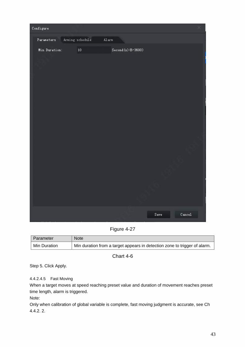
Figure 4-27
Parameter Note Min Duration Min duration from a target appears in detection zone to trigger of alarm.
Chart 4-6
Step 5. Click Apply. 4.4.2.4.5 Fast Moving When a target moves at speed reaching preset value and duration of movement reaches preset time length, alarm is triggered. Note: Only when calibration of global variable is complete, fast moving judgment is accurate, see Ch 4.4.2. 2.

44
Figure 4-28
Step 1. Click Add rule. Step 2. Enable rule and modify rule name and type.
1. Enable rule, means to enable corresponding IVS rule.
2. Modify rule name. 3. In Rule type dropdown list, select Fast-moving.
Step 3. In monitoring video, draw detection zone, and right click to stop drawing. Note: Select existing detection zone, click Clear or Re-draw to draw again.
Step 4. Set parameter, arm time and alarm link. Draw target filter, see Ch 4.4.2.4.1. See Figure 4-29.

45
Figure 4-29
Parameter Note Min Duration Min duration of target fast moving in detection zone. Sensitivity The higher the sensitivity is, the easier to trigger alarm while more
interference will be caused. Default setup is recommended.
Chart 4-7
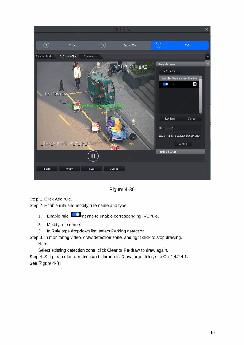
Step 5. Click Apply. 4.4.2.4.6 Parking Detection When a target parks in detection area over a certain time, alarm is triggered.
46
Figure 4-30
Step 1. Click Add rule. Step 2. Enable rule and modify rule name and type.
1. Enable rule, means to enable corresponding IVS rule.
2. Modify rule name. 3. In Rule type dropdown list, select Parking detection.
Step 3. In monitoring video, draw detection zone, and right click to stop drawing. Note: Select existing detection zone, click Clear or Re-draw to draw again.
Step 4. Set parameter, arm time and alarm link. Draw target filter, see Ch 4.4.2.4.1. See Figure 4-31.

47
Figure 4-31
Parameter Note
Min Duration Min time period between target vehicle appearance in detection and alarm trigger.
Chart 4-8
Step 5. Click Apply. 4.4.2.4.7 Crowd Gathering When crowd gathers in detection zone and exceeding set quantity of people, alarm is triggered.

48
Figure 4-32
Step 1. Click Add rule. Step 2. Enable rule and modify rule name and type.
1. Enable rule, means to enable corresponding IVS rule.
2. Modify rule name. 3. In Rule type dropdown list, select Crowding gathering.
Step 3. In monitoring video, draw detection zone, and right click to stop drawing. Click min crowd gathering zone, adjust size by dragging the four angles. Note: Select gathering zone or min gathering zone, click Clear to delete gathering zone and
min gathering zone. Select gathering zone or min gathering zone, click Re-draw to draw again.
Step 4. Set parameter, arm time and alarm link. Draw target filter, see Ch 4.4.2.4.1. See Figure 4-33.

49
Figure 4-33
Parameter Note
Min Duration Min time period between people gathering in detection and alarm trigger.
Report Interval When alarm is triggered, if alarm event still exists, then you can set interval to alarm again and again.
Sensitivity The higher the sensitivity is, the easier to trigger alarm while more interference will be caused. Default setup is recommended.
Chart 4-9
Step 5. Click Apply. 4.4.2.4.8 Missing Object When an object is moves out from detection zone, alarm is triggered.

50
Figure 4-34
Step 1. Click Add rule. Step 2. Enable rule and modify rule name and type.
1. Enable rule, means to enable corresponding IVS rule.
2. Modify rule name. 3. In Rule type dropdown list, select Missing object.
Step 3. In monitoring video, draw detection zone, and right click to stop drawing. Note: Select existing detection zone, click Clear or Re-draw to draw again.
Step 4. Set parameter, arm time and alarm link. Draw target filter, see Ch 4.4.2.4.1. See Figure 4-35.

51
Figure 4-35
Parameter Note
Min Duration Min time period between the object leaves detection zone and alarm trigger.
Chart 4-10
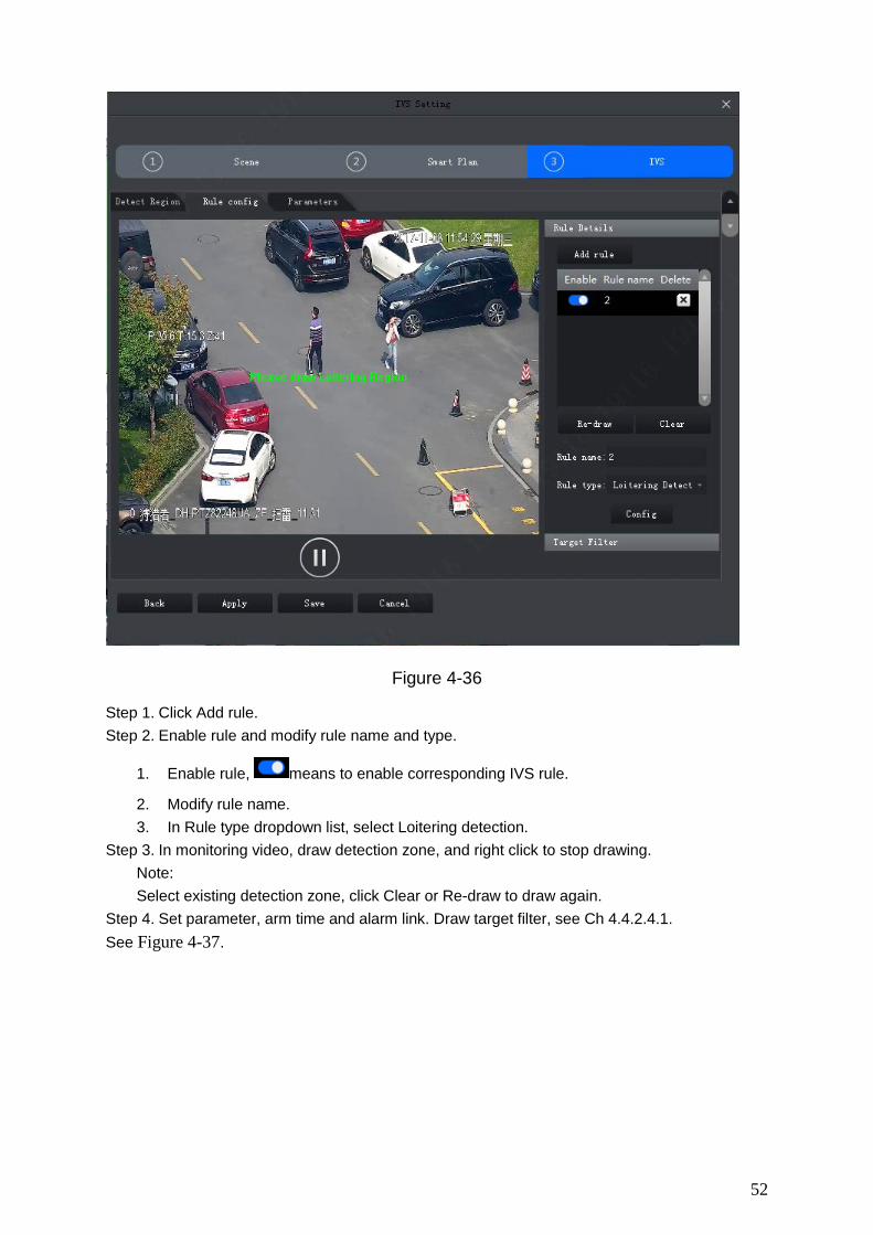
Step 5. Click Apply. 4.4.2.4.9 Loitering Detection When a target stays too long over set time length in detection zone, alarm is triggered.
52
Figure 4-36
Step 1. Click Add rule. Step 2. Enable rule and modify rule name and type.
1. Enable rule, means to enable corresponding IVS rule.
2. Modify rule name. 3. In Rule type dropdown list, select Loitering detection.
Step 3. In monitoring video, draw detection zone, and right click to stop drawing. Note: Select existing detection zone, click Clear or Re-draw to draw again.
Step 4. Set parameter, arm time and alarm link. Draw target filter, see Ch 4.4.2.4.1. See Figure 4-37.
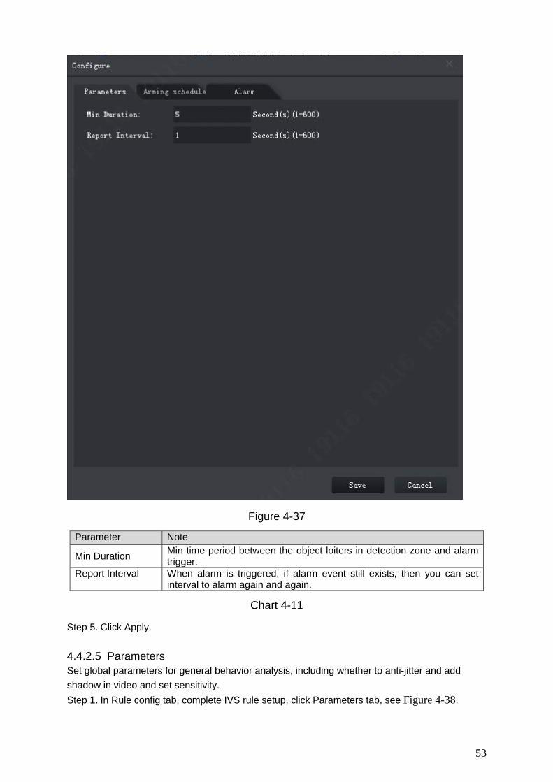
53
Figure 4-37
Parameter Note
Min Duration Min time period between the object loiters in detection zone and alarm trigger.
Report Interval When alarm is triggered, if alarm event still exists, then you can set interval to alarm again and again.
Chart 4-11
Step 5. Click Apply. 4.4.2.5 Parameters Set global parameters for general behavior analysis, including whether to anti-jitter and add shadow in video and set sensitivity. Step 1. In Rule config tab, complete IVS rule setup, click Parameters tab, see Figure 4-38.

54
Figure 4-38
Step 2. Set parameter, see Chart 4-12. Parameter Note Disturbance Filter
Filter disturbance of random swing (i.e. water wave and etc.), generally used in outdoor environment. This function may cause miss-detection.
Shadow Filter Filter shadow, if not enabled, then system will auto detect target shadow.
Sensitivity Sensitivity of control target. The lower the value, the less wrong detection will be, but missed detection will be more.
Sensitivity is from low to high with scene from fewer to more.
Chart 4-12
Step 3. Click Save.
4.5 Smart Track Config (Fisheye+Dome) Smart track (fisheye+dome) sets fisheye camera as master camera with panorama view, and sets speed dome as slave camera.
Calibration Requirement To improve calibration success rage and accuracy, please follow: Calibrate at least 3 groups, max 10 groups. 4 groups is recommend.

55
Start from far to close by clockwise or counterclockwise direction. Point of calibration shall be even.
Calibrate position with obvious traits, such as cross of object corner. See Figure 4-39 and Figure 4-40 Bad Calibration.
Figure 4-39 Good Calibration
Figure 4-40 Bad Calibration
Calibrate Camera
Step 1. On device tree select fisheye device, right click select Smart Track Config, see Figure 4-41.

56
Figure 4-41
Step 2. Link speed dome. See Figure 4-42.
Figure 4-42
1. In Link Speed Dome area, click next to fisheye name.
2. In speed dome dropdown list, select speed dome. 3. Click Save. See Figure 4-43.

57
Figure 4-43
Step 3. Add calibration point. 1. Click Add, you will see a cross sign and a new record generated. 2. Drag fisheye cross sign to appropriate position.
Note: To improve calibration accuracy, please use far object as reference for first group.
Other calibrations points can be clockwise or counterclockwise distributed. Calibrate position with obvious traits, such as cross of object corner.
3. In speed dome image, adjust speed dome position to make center of speed dome match the cross sign of fisheye. See Chart 4-13.
Icon Name Note
Zoom Zoom in/out speed dome
Focus Adjust speed dome focus
Iris Adjust speed dome brightness
E-mouse Electronic mouse
Quick Position
Click this icon, drag mouse in monitoring video, select area, then video automatically adjust by making pane as center.
Chart 4-13
4. Click to save calibration info.
5. Repeat step 1~4 to complete remaining calibration position. N 6. Click OK.

58
Achieve Smart Track (Fisheye and Dome)
After you complete calibration, you can view link effect in smart track interface. Step 1. On device tree, select fisheye device, right click Smart Track. See Figure 4-44.
By default link mode is enabled, click and you can switch between fisheye
correction mode and link mode. To enable fisheye correction, you can select installation method and view mode in fisheye preview window. Refer to Ch 4.8.
On the left you can set PTZ, refer to Ch 4.7.
Figure 4-44
Step 2. Execute the following operation to see link effect. Link
Click any position in fisheye channel, speed dome will rotate to corresponding position and auto adjust zoom, see Figure 4-45.
Figure 4-45

59
Pane link Select panel in fisheye video, speed dome rotates to corresponding area, see Figure 4-46.
Figure 4-46
Drag link Drag position calibration in fisheye video, speed dome rotates with the calibration, see Figure 4-47.
Figure 4-47
4.6 Smart Track Config (Dome+Fixed) After you have configured dome and fixed camera linkage, when intelligent rule of fixed camera triggers alarm, speed dome auto links to corresponding position and tracks object until the object exceeds monitor range or tracking time limit.
Calibration Requirement To improve calibration success rage and accuracy, please follow: Calibrate at least 4 groups, max 8 groups. 4 groups is recommend.

60
Start from far to close by clockwise or counterclockwise direction. Point of calibration shall be even.
Calibrate position with obvious traits, such as cross of object corner. See Figure 4-48.
Figure 4-48 Good Calibration
Calibrate Camera Step 1. Select fixed camera on device tree, right click Start Track Config, see Figure 4-49.
Figure 4-49
Step 2. Link speed dome, see Figure 4-50.

61
Figure 4-50
1. In link speed dome area, click .
2. Click and in dropdown list select speed dome.
3. Set tracking, see Parameter Note Expected magnification
Link speed dome tracking magnification.
Vertical magnification desired angle
Link speed dome vertical magnification desired angle.
Tracking time Support setup of upper limit and lower limit. If tracking reaches min limit, current tracking can be interrupted. If a
new target appears, it will track new target. If tracking reaches max limit, tracking end.
Idle time Select Enable, enable idle time and then when there is no target in fixed camera and reaches set time, speed dome returns to preset point.
Chart 4-14
4. Click Save, see Figure 4-51.

62
Figure 4-51
Step 3. Calibrate fixed and dome, see Figure 4-52.
Figure 4-52
1. Click Add, a cross appears in video and meantime a record is generated. 2. Drag cross to appropriate position. Note: Start from far to close by clockwise or counterclockwise direction. Point of calibration
shall be even. Calibrate position with obvious traits, such as cross of object corner. 3. In video of speed dome, adjust speed dome position via icon below to make center of
speed dome match + in fixed camera video.
Icon Name Note

63
Icon Name Note
Zoom Zoom in/out speed dome
Focus Adjust speed dome focus
Iris Adjust speed dome brightness
E-mouse Electronic mouse
Quick Position
Click this icon, select any position to monitor, then you can adjust image with this position as center.
Chart 4-15
4. Click to save calibration info.
5. Repeat step 1~4, complete remaining calibration config. Note: Each speed dome calibrate at least 4 groups, max 8 groups. 4 groups is recommend. 6. Select preset return point.
When fixed camera video has no tracking to reach set length, speed dome can return to set preset.
7. Click OK, to save. Successfully calibrated fixed camera, and system feedbacks. If failed, it will inform calibration failed and please try again.
Achieve Smart Track (Fixed and Dome) After you complete calibration, you can view link effect in smart track interface. Step 1. On device tree, select IPC device, right click Smart Track. See Figure 4-44.
On the left you can set PTZ, refer to Ch 4.7.
Figure 4-53

64
Step 2. Execute the following operation to see link effect. Manually position
Click any position in fixed camera video, link to speed dome. Speed dome will rotate to the corresponding position, see Figure 4-54.
Figure 4-54
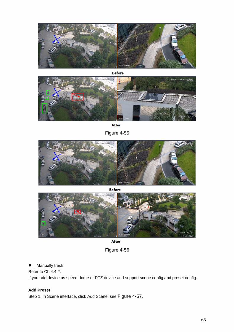
3D Position In fixed dome video pane select, speed dome will rotate to corresponding area and meantime zoom in/out. Draw box from upper left to lower right, and zoom in when speed dome is fixed, see Figure 4-55. Draw box from lower right left to upper left, and zoom in when speed dome is fixed, see Figure 4-56.
65
Figure 4-55
Figure 4-56
Manually track Refer to Ch 4.4.2. If you add device as speed dome or PTZ device and support scene config and preset config. Add Preset Step 1. In Scene interface, click Add Scene, see Figure 4-57.

66
Figure 4-57[A3]
Step 2. Via PTZ direction control, rotate camera to designated position. Note: Step length can control PTZ speed, within 1~8 step length.
Step 3. Click Save. Modify Preset Step 1. In Scene interface, select preset to modify, see Figure 4-57. Step 2. Via PTZ direction control, rotate camera to designated position.
Note: Step length can control PTZ speed, within 1~8 step length.
Step 3. Click Save. Delete Preset Step 1. In Scene interface, select preset to delete, see Figure 4-57. Step 2. Click Delete.
Note:
To ensure accuracy of manually tracking, please click at the upper right corner to
disable tracking. Icon become .

67
In fixed dome video monitoring, click moving target box (inside box is OK), target box changes color, and speed dome select target.
Figure 4-58
4.7 PTZ PTZ of different devices have different setup interfaces, subject to actual condition. See the following figures and charts.
Figure 4-59
Parameter Note
Zoom Click or to adjust zoom.
Switch to PTZ Click Switch to PTZ, system jumps to PTZ control.

68
Focus Click or to adjust definition.
Auto Focus Click Auto Focus to auto focus.
Reset Focus Click Reset Focus to reset.
Figure 4-60
Parameter Note
Menu Click go to PTZ menu.
Mouse stimulation Click , via mouse operate PTZ.
Direction Set PTZ direction in 4 directions.
3D position Click , and draw a box in video monitoring, PTZ will rotate and focus to this scene.
Step Control PTZ rotation speed, can be set 1 to 8 different rotation step.
Zoom Click or to adjust zoom.
Focus Click or to adjust definition.
Iris Click or to adjust brightness.

69
Parameter Note
Preset
By setting the Preset, you can quickly go to the preset position corresponding to the camera. Preset setting For details, see Ch 4.7.1.
Note: You can set up to 128 presets.
Tour
By setting Cruise, the camera can cruise between different preset points.Cruise setting details, see Ch 4.7.2. Note:
You can set up to eight cruise group.
Horizontal rotation
By setting Horizontal rotation, the camera can be rotated horizontally.
in , Select Horizontal rotation
and click , turn on horizontal rotation.
Scan By setting the two borders, the camera rotates repeatedly between the two borders. Scan settings For details, see Ch 4.7.3.
Pattern By setting the Tour track, the user operation during the rotation of the camera recorded, the camera can be rotated according to the track record. Patrol track setting details, see Ch 4.7.4.
AUX With aux, aux commands can be entered to turn on the aux points.
Windshield wiper Click to control wiper.
Preset
By setting the preset point, you can quickly go to the preset position corresponding to the camera. Step 1. Via PTZ direction control the camera to designated position.
Step 2. In select preset, click .
Step 3. In select preset no., enter preset name.
Step 4. Click to save preset.
Step 5. Click to delete non-necessary preset.
Step 6. Select preset and click , camera rotates to corresponding position.
Tour
By setting the tour, the camera can tour between the different preset points. Warning:

70
Set at least two presets before you can tour.
Step 1. In , select tour, and click . See Figure 4-61.
Figure 4-61
Step 2. Set tour no. and tour name. Step 3. Select preset.
a) In Preset list select preset, and enter time.
b) Click to add preset.
Repeat this step to add more presets. Step 4. Click OK.
Step 5. You need to select tour no., click so camera will tour among different presets.
Scan By setting the two borders, the camera rotates repeatedly between the two borders.
Step 1. In select Scan.
Step 2. By control PTZ direction, rotate PTZ to designated left position, click to set left border.
Step 3. By control PTZ direction, rotate PTZ to designated right position, click to set right
border.

71
Step 4. Click to repeat rotation among two borders.
Pattern
Record down camera rotation process, via pattern rotation function.
Step 1. In select Pattern.
Step 2. Click to start to set pattern, and zoom, focus or rotate camera.
Step 3. Click to complete.
Step 4. Select pattern no., click , camera rotate pattern according to record.
Enable Windshield Wiper When speed dome has windshield wiper, SmartPSS can control windshield wiper.
Step 1. In select wiper.
Step 2. Click to wipe speed dome once.
4.8 Fisheye View Mode Only fisheye device supports installation and view mode, different installation modes corresponding to view mode referring to the following chart.
parameter Description
View mode
Current video screen (by default support the original image mode), in accordance with the different installation methods, with other different presentation as follows:
• Ceiling: 1P + 1, 2P, 1 +2, 1 +3, 1 +4, 1P +6, 1 +8. • Wall mount: 1P, 1P + 3, 1P + 4, 1P + 8. • GND: 1P +1,2 P, 1 +3, 1 +4, 1P +6, 1 +8.
Note: When switching installation mode, by default show the original image mode.
Ceiling/wall mount/GND original
image That is the original image has not been corrected.
Ceiling 1 + 2
That is the original video +2 independent sub videos and the sub-frame in sub video and original image support zoom, move.
Ceiling/ wall mount
1P + 1
As 360 ° rectangle panoramic + independent sub video, and sub-frame in sub video and original rectangle panoramic support zoom, move. Rectangle panoramic also supports move of left/right starting point.
2P
As two linked 180° rectangle video, at any moment the two windows form a 360° panorama, as “dual panorama”. Two rectangle video both support move of left/right starting point and link each other.

72
1 + 3 As original image +3 independent sub videos and the sub-frame in sub video and original image support zoom, move.
1 + 4
As original image +4 independent sub videos and the sub-frame in sub video and original image support zoom, move. Original video also support move of left/right starting point.
1P + 6
As 360 ° rectangle panoramic +6 independent sub videos, and sub-frame in sub video and original rectangle panoramic support zoom, move. Rectangle panoramic also supports move of left/right starting point.
1 + 8 As original image +8 independent sub videos and the sub-frame in sub video and original image support zoom, move.
Wall mount
1P As 360° rectangle panoroma from left to right, 180° rectangle panorama support up/down move to change to vertical view.
1P + 3
As 360° rectangle panorama +3 independent sub video, and the sub-frame in sub video and original image support zoom, move. Rectangle panorama support up/down move to change to vertical view.
1P + 4
As 360° rectangle panorama +4 independent sub video, and the sub-frame in sub video and original image support zoom, move. Rectangle panorama support up/down move to change to vertical view.
1P + 8
As 360° rectangle panorama +8 independent sub video, and the sub-frame in sub video and original image support zoom, move. Rectangle panorama support up/down move to change to vertical view.
4.9 Device Preview via NKB1000 Keyboard Via NKB1000 keyboard, you can enable device preview, split preview window, control PTZ, close preview video and etc. Condition Set and record device no. of device to be operated. Keyboard connected PC where SmartPSS is installed. Logged in SmartPSS interface and open preview. Step Step 1. Connect keyboard, power indicator is ON. After it is running, LCD shows welcome
interface. Click OK or Set key. Step 2. Via rocker, enter username and password, click OK. It shows homepage.
Note: Admin user has default password as 888888.
Step 3. Via rocker, left/right select mode to be preview, and click OK. Step 4. Operate preview interface, see Chart 4-16.
Function Note Split Window Click 【window number】, and then click 【split】to split

73
windows. Window number of number of split.
Enable Preview By sequence of 【window no.】 and 【ID】 key, select preview window and then click 【device no.】 and 【channel】 key to enable corresponding preview video of device.
Window no. is 1 at upper left corner, starting from left to right, up to down.
Close Preview Click 【window no.】 and 【ID】 key respectively. Select window in preview, and click 【0】 and 【channel】 key. Close corresponding preview video.
Window no. is 1 at upper left corner, starting from left to right, up to down.
PTZ Control Enable speed dome video preview and keyboard in being operated. You can control speed dome direction, adjust it is, focus, zoom and etc. Via rocker, rotate in up, down, left, right, up left, up right,
down left and down right directions. Click【iris】+ or -, adjust iris. Click 【zoom】+ or -, adjust video definition. Click 【zoom】+ or -, adjust zoom.
Chart 4-16

74
5. Tour & Task
5.1 Config Task Plan By setting tour plan, you can tour each window.
Step 1. Click , and click Tour & Task.
Step 2. Add tour plan. 1. Click Add. See Figure 5-1.
Figure 5-1
2. Modify task plan name. When you add new task, you can edit task name immediately. Or you can double click
tour plan name or click to modify tour plan name.
Step 3. Set task. It supports to set multiple task. Here takes one task as example.
1. Click . See Figure 5-2.
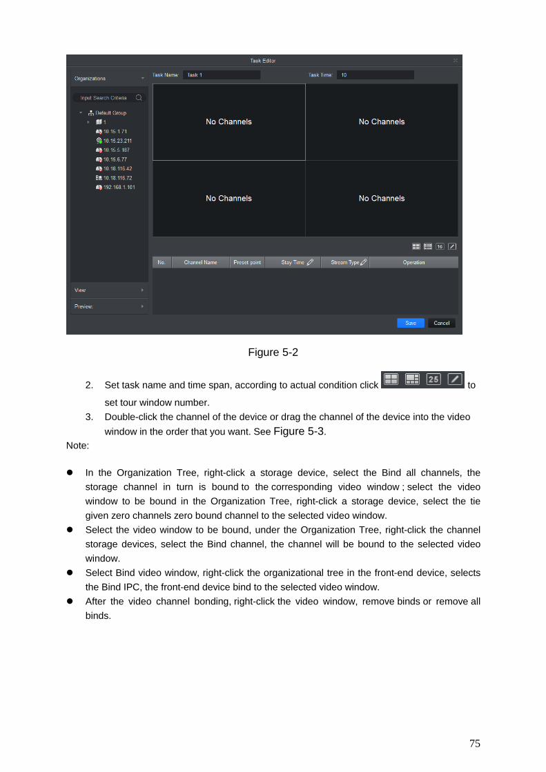
75
Figure 5-2
2. Set task name and time span, according to actual condition click to
set tour window number. 3. Double-click the channel of the device or drag the channel of the device into the video
window in the order that you want. See Figure 5-3. Note:
In the Organization Tree, right-click a storage device, select the Bind all channels, the storage channel in turn is bound to the corresponding video window ; select the video window to be bound in the Organization Tree, right-click a storage device, select the tie given zero channels zero bound channel to the selected video window.
Select the video window to be bound, under the Organization Tree, right-click the channel storage devices, select the Bind channel, the channel will be bound to the selected video window.
Select Bind video window, right-click the organizational tree in the front-end device, selects the Bind IPC, the front-end device bind to the selected video window.
After the video channel bonding, right-click the video window, remove binds or remove all binds.

76
Figure 5-3
4. Set channel preset, time span, stream type and channel sequence. Note:
Click of the corresponding channel, in the left preview screen to display live
preview or e-map information.
Click or of the corresponding channel, adjust the channel sequence in the
task.
Click of the corresponding channel, delete the corresponding channel.
5. Click Save, See Figure 5-4.

77
Figure 5-4
Step 4. Set tour task. When you set multiple tasks, it support task plan by day or week.
1. Click to run the plan. See Figure 5-5.

78
Figure 5-5
2. Select device type. Day plan, period is day. There are many different periods in a day. Week plan. There are 7 periods in a week.
3. Select tour plan, set time, click Add. 4. Set different period task, click Save.
5.2 Enable Task If your device sets schedule, then within set time system will auto plays video according to task. If you want to manually tour, priority of manual task must be over scheduled task. Step 1. In New function tab, click Live View. Step 2. In the interface, select tour plan.
Step 3. Click to enable task plan.

79
6. Playback
6.1 Playback You can playback and export device record, device picture, local record and local picture.
In New tab, click select Playback, see Figure 6-1.
Figure 6-1
No. Task Note
1
Playback video
You can play back the recording device. For details, see Ch 6.2.
Playback image
You can picture playback device. For details, see Ch 6.4.
Playback local video
You can play back the local video. For details, see For details, see Ch 6.6.
Playback local picture
You can play back the local picture. For details, see For details, see Ch 6.8.
Organization Tree / Area Tree
When the Default Device Tree is set to Device Tree (by device), the device tree displays the grouping and channels for the device.
When a default device tree is set to Area Tree (by channel),

80
the device tree display channel.
Default Device Tree setting, see Ch 8.
Logout and login
When the Default Device Tree is set to Device Tree (by device), right-click the device and select Logout. The software and device are disconnected. After logging out, right-click the device, select Login, reconnect device.
View In the Device tab, click behind View . Open View interface, playback view video device.
2
View playback stream information
Choose video window with open video, in status bar it displays the playback stream information.
Snapshot
Select open video window, click or right-click to select Snapshot, Snapshot a single picture. You can click in the homepage, modify the path to save the picture.
Zoom Select open playback video window, click .
Close window
Select Open playback video window, click or right click to select Close Window .
Close all windows
Select the video window, right-click to select Close all windows .
IVS Overlay Overlay IVS info, include rule and object box.
3
Set aspect ratio
Select the video window, right-select Window Scale, select the video aspect ratio.
Enable Audio
You can turn on the audio through the following two ways.
Select open playback video window, right-select Audio. Playback control toolbar at the click , and adjust the
volume.
4
Set the device record search criteria
In the Devices tab, select the device or view, select Record, set the record type, stream, start time and end time, click Search, the recording information is displayed in the schedule box.
Record type includes all types of video record, general record, alarm record, motion detection record, intelligent record and card record.
Stream includes main stream and sub stream. Interval of start time and end time must be within a day.
Set the device picture search
In the Devices tab, select the device, or view, select Picture, set the start time and end time, click Search, image information is displayed in the playback window. Interval of start time and end time must be within a day.

81
criteria
5 Time progress bar
Show existing video display information.
6
View progress bar
Click to view the video or image export progress and export results.
Export record
Export device video files, see Ch 6.3.
Export picture
Export device picture files, see Ch 6.5.
Export local record
Export local video files. See Ch 6.7.
Open Video In the Local>
Smart search
Select open playback video window, click , in the video
playback window, select the smart search, click device again. The software will search for the video motion detection,
click to exit the smart search.
7 Playback control toolbar
Control video playback and audio.
Video playback from the same point in time for all channels.
Reverse video playback.
Start video playback.
Pause video playback.
Stop video playback.
Single frame backward playback.
Single-frame forward playback.
Adjust the playback speed.
8 Set the video window display mode
In select the desired video window
display mode or select to customize video window display mode.
Click or select the video window, right select full screen, video window full screen display.
9 Video file list Click the icon to expand the list of the corresponding channel video file, you can select video files for playback and export the

82
corresponding video file.
6.2 Playback Device Record Condition There is device record inside channel. Steps: Step 1. In playback interface, click Device tab. Step 2. In Organization Tree, select device channel or select view in View. Step 3. Select record and set record search criteria.
a) Select record type and stream, and set time. b) Click Search.
Step 4. Select window with record, click . See Figure 6-2.
Figure 6-2
6.3 Export Device Record Condition There is device record inside channel. Steps: Step 1. In playback interface, click Device tab.

83
Step 2. In Organization Tree, select device channel or select view in View. Step 3. Set record search criteria.
a) Select record type and stream, and set time. b) Click Search.
Step 4. Select window with record, click .
Step 5. Click , system select one record, and adjust record part according to actual need,
click again to export record. See Figure 6-3.
Figure 6-3
Step 6. Select export path and format. Note: When the Export Format is set to Original Format, please also check the Export Smart Player, export original format player. Step 7. Click OK. The system displays the playback stop information, click OK. The system displays the Export Progress dialog box, as Figure 6-4 below. After recording the download is complete, the system prompts the download is complete. Click Exporting tab, you can view the video download progress, pause the video being exported to continue downloading the paused video, download again the video failed and delete exporting video; click exported tab, you can view download history and open video storage path.

84
Figure 6-4
6.4 Playback Device Picture Condition There is device picture inside channel. Steps Step 1. In Playback interface, select Device tab. Step 2. In Organization Tree, select device channel or in View select view. Step 3. Select picture and set time. See Figure 6-5.
Click on the right, you can open and close device picture list.
In device picture list, click , device picture list will be shown in format of list; click , device
picture list is shown in format of thumbnail.

85
Figure 6-5
Step 4. Playback picture. Manual playback: Click Next or Preview.
Auto playback: Set auto play interval, click to auto play(it switch to ), system
will auto playback local picture.
6.5 Export Device Picture Step 1. In Playback interface, select Device tab. Step 2. In Organization Tree select device channel or in View select view. Step 3. Select Picture and set time.
Step 4. Click on the right, to export device picture.
Step 5. Click . See Figure 6-6.

86
Figure 6-6
Step 6. Select export path, click OK. See Figure 6-7. Click Exported tab, you can view download record, open picture storage path and delete downloaded file.
Figure 6-7
6.6 Playback Local Record Condition There is local record in the channel, see Ch 4.1. Steps Step 1. In Playback interface, select Local tab. Step 2. Click Record tab.
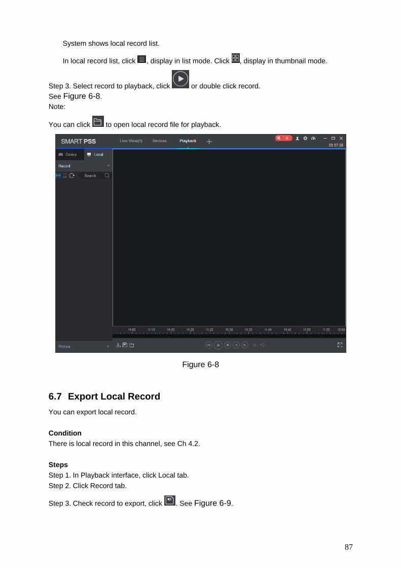
87
System shows local record list.
In local record list, click , display in list mode. Click , display in thumbnail mode.
Step 3. Select record to playback, click or double click record. See Figure 6-8. Note:
You can click to open local record file for playback.
Figure 6-8
6.7 Export Local Record You can export local record. Condition There is local record in this channel, see Ch 4.2. Steps Step 1. In Playback interface, click Local tab. Step 2. Click Record tab.
Step 3. Check record to export, click . See Figure 6-9.

88
Figure 6-9
Step 4. Select export path and format. Note: When Export Format is set to Original Format, please check Export Smart Player to export.
Step 5. Click OK. The system displays the Export Progress dialog box, as Figure 6-10 shown. After record download is complete, the system prompts the download is complete. Click Exporting tab, you can view the video download progress, pause the video being exported, resume download paused, and delete videos which being exported; click Exported tab, you can view the download history, open video storage path and delete the downloaded file.
Figure 6-10
6.8 Playback Local Picture

89
Condition There is local picture in the channel, see Ch 4.1. Steps Step 1. In Playback interface, select Local tab. Step 2. Click Picture tab.
System shows local record list.
In local picture list, click , display in list mode. Click , display in thumbnail mode.
Step 3. Select picture to playback, click or double click picture See Figure 6-11.
Figure 6-11
Step 4. Playback picture. Manual playback: Click Next or Preview.
Auto playback: Set auto play interval, click to auto play(it switch to ), system
will auto playback local picture.

90
7. Log Search
7.1 Search Client Log Step 1. In New tab, click Log.
Step 2. Select . System shows Client interface. Step 3. Set time, type, keyword. Client log includes system log, operation log and alarm log. Step 4. Click Search. See Figure 7-1. Note: After log is successfully searched, you can click Export to export log.
Figure 7-1
7.2 Search Device Log Step 1. In New tab, click Log.
Step 2. Select .
Step 3. Set time, type, and device. Client log includes system log, config log, storage log and etc. Step 4. Click Search. See Figure 7-2. Note: After log is successfully searched, you can click Export to export log.

91
Figure 7-2

92
8. System Config You can set up base info, preview and playback, event, log, system and language, hot keys, and local path, backup/restore.
Step 1. In homepage, click . See Figure 8-1.
Figure 8-1
Step 2. Set parameters, see the following chart. Parameter Type Parameter Note
Base Initial page Select page shown when you open the software, including new feature page preview interface and will recovery not closed tabs
Maximum behavior
Maximize display software, including full screen and maximized window.
Minimum behavior
Check show floating window, display floating window when the software is minimized.
Default video scale
Set the preview or playback video default ratio, including the original scale and full screen.
Default device Set the preview, playback and other interface devices tree

93
tree display formats. Modify this parameter to take effect after the restart the software needed.
Include following options:
Device tree (according to device): grouping by device Area tree (according to channel): grouping by channel
Audio NE Level Set audio NE level within 1~5.
Preview and Playback
Default Stream Type
Set stream type of preview, including mains stream, sub stream, and self-adaptive stream.
Instantly Replay Time
Set at time instant replay of the preview screen.
Resume last preview
Check the Resume last preview software record video window status when closing software, and after re-login open the preview screen, the video will be restored as before the software is closed.
Show IVS Rule Show IVS rule in preview and playback video.
Save Device Tree Selection
Select Save Device Tree Selection, after record search end, device will keep selected status.
Device Show device channel number
Check the Show device channel number, then in Device interface software automatically assigns a unique no. to device, you can modify this no. This no.of device is used for keyboard.
Auto login device
Check the Auto login device, restart the software, the software automatically logged added device. Modify this parameter to take effect after the restart the software as needed.
Auto fill user and key
Check the Auto fill user and key, enter your username and password, the software automatically login added device according to the username and password.
If the login username and password set are the same as user and password of the device, then login is successful, otherwise the login fails.
Event Loop Check the Loop, looping alarm when an event occurs.
Global wav Check the Global wav, select audio file path, then all alarms shall play the audio file.
Not check the Global wav, select different types of events and events in the drop-down list, and separately set their corresponding audio file.

94
SMTP Enable SMTP (email) and set email info, when an event occurs, it will send an email.
Log Log saved time Setting the log storage time, modification to this parameter will be effective only after this software is restarted.
System and Language
Network ability Set the network according to actual network performance.
Auto check time
Check the Auto check time, and set the corresponding point in time, when the software is open during sync time, and device added on client automatically synchronize with your local PC time.
Check time Click Check time, device added on client immediately synchronization time.
Language Set the language of the software, modify this parameter to take effect after the restart the software as needed.
Hotkeys Set shortcut keys for common operations systems. Double click the hotkey column in the corresponding function of the hotkey, then set the hotkey function on the keyboard, click the Apply, modify the corresponding hotkey function.
Click Reset to restore default software.
Common operations include preview full-screen, open playback module, open event module, open system configuration, open tour plan configuration, enable/disable tour plan, snapshot, lock, switch users, open / close linkage video, turn on / off video .
Local Path Pic path Set picture path.
Record path Set record path.
Backup/Restore Backup Click Backup to back up config file,
Restore Click Restore, and select exported config file to restore config.
Step 3. Click Save.

95
9. User
9.1 Role Info You can add, modify and delete role. Step 1. In New tab, click User, see Figure 9-1.
Figure 9-1
Step 2. Click . See Figure 9-2.

96
Figure 9-2
Step 3. Set role name and fill in remark. Step 4. Check menu right of the role, and select tab and set role channel right in Channel right
area. Note: When user of the corresponding role logins client, and in New tab it does not show non-allocated menu right, and in corresponding device tree it does not show non-allocated channel right. Step 5. Click Save.
Note: Admin has all rights which cannot be modified or deleted. After a role is added, you can modify its right or delete it. Warning: When you delete a role, users of this role will also be deleted.
9.2 User You can add, modify and delete user. Step 1. In New tab, click User. See Figure 9-3.
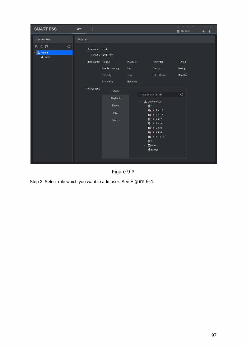
97
Figure 9-3
Step 2. Select role which you want to add user. See Figure 9-4.

98
Figure 9-4
Step 3. Set user parameter, see the following chart. Parameter Note
Username Username which cannot repeat existing username.
Role Select a role the user belongs. Different user permissions are for different roles.
Password The user's password and confirm the password.
Confirm
Remark Description of the user information.
Menu rights
According to the actual need select the user's menu rights
Channel rights
According to the actual need select the user's channel rights
Step 4. Click Save.
Note: Admin has all rights which cannot be modified or deleted. After a role is added, you can modify its right or delete it.

99
10. Device Config You can update software, connect to WEB, configure device camera, network, PTZ, event, storage, system and etc. In New tab, click Device CFG, see Figure 10-1. Different devices may have different parameters, subject to actual device and manual.
Figure 10-1
No. Task Note
1 Device Select device, you can view the device's IP address, device model, software version and serial number.
Upgrade Select device, click the Upgrade, you can upgrade the device program.
Link to WEB Select the device, click the Link to WEB, can be linked to WEB config interface.
2 Camera Select device, open the Camera . Click Remote Device, you can search device and add
the device or remove device. Click the Camera, you can configure the camera
attributes, operations, management or head profile. Click the Video, you can configure the video code, or
snapshot stream video overlay information. Click the Audio, you can configure the audio code
stream, input type and volume.
Network Select the device, open the Network tab.

100
Click TCP / IP, you can configure a static IP address of the device or the device to obtain an IP address via DHCP.
Click Connect, you can configure the maximum number of connected devices and the port number to use when connecting.
Click PPPOE, you can configure the PPPoE username and password to access the device via PPPoE dialing.
Click DDNS, you can configure the device and DDNS server domain names, access device through its domain name.
Click the IP Rights, you can configure a whitelist and blacklist devices.
Click SMTP (e-mail), you can configure the device's SMTP server and mailbox information when the device is configured alarm linkage and alarm messages, the recipients of the message recipient to send alarm information.
Click FTP, the device can be configured FTP upload information and pictures, pictures in the manner set upload FTP appropriate directory.
Click Multicast, you can configure the multicast address and port, through surveillance video multicasts.
Click Alarm Center, you can configure the alarm center host IP address and timing login time.
PTZ Select device, open PTZ tab. Click PTZ, you can configure PTZ and stimulate PTZ.
Configuring event parameters
Select the device, open Events tab.
Click the Video Detect, you can configure motion detection, video loss detection, video tampering detection and defocus detection.
Click the Audio Detect, you can configure audio input and sound intensity abnormality.
Click Intelligent Analysis, can mark video quality diagnosis, general behavioral analysis, face detection, people counting and depth of field heat map.
Click Alarm I/O, you can configure the alarm inputs and alarm linkage information.
Click Abnormality, you can configure no space, storage device error, IP conflict and etc.
Storage Select device, open Storage.
Click Schedule, you can configure the video snapshot and snapshot plan.
Click HDD Manager, you can configure and view locally stored information about the device, configure the FTP server.
Click the Record, you can configure the video stream control method.
System Parameters
Select the device, open the System tab.
• Click General, you can basic information and

101
time. • Click PTZ, you can configure the analog PTZ information. • Click Account, you can add, delete users and user groups. • Click Maintenance, you can configure serial information, system configuration and maintenance information plus view version information.

102
11. Event Config
11.1 Event Type In New tab, click Event Config, see Figure 11-1. Note: Client shows all event types, different devices support different event types, subject to actual device.
Figure 11-1
The event type Event Note Condition
Channel event Video loss Network abnormality causing video loss
Video loss detection is ON.
Video tampering Event is generated when video is tampered.
Video tampering is ON.
Motion detect Event is generated when it is detected moving object in video.
Motion detect is ON.
Audio abnormal Event is generated Audio abnormal

103
when the audio connection is abnormal.
is ON. .
Audio mutation Event is generated when the sound suddenly changed.
Audio mutation is ON.
Defocus detect Event is generated when defocus occurs.
Defocus detect is ON.
IPC External Alarm For only NVR/HCVR. Check external alarm input of IPC connected to NVR/HCVR.
N/A
IPC Offline Alarm For only NVR/HCVR. Check event occurs when IPC disconnected to NVR/HCVR.
N/A
IVS Alarm Tripwire Event is generated when the target cross line from set direction.
Tripwire is ON.
Cross warning zone
Event is generated when the object enters or leaves the area, or the target appears in the region.
Cross warning zone is ON.
Scene switch Event is generated when the scene changes.
Scene switch is ON.
Abandoned object detection
Event is generated when the monitor screen have left more than the target time set by the user.
Items turned legacy detection.
Missing object detection
Event is generated when the monitor screen after the target is removed over a certain time.
Items move detection is turned on.

104
Face detection Event is generated when the monitor screen detects the person's face.
Face detection is ON.
Loitering detection Event is generated when the target continuously present in the monitored area longer than the set time.
Loitering detection is ON.
Crowd gathering estimation
Event is generated when the crowd gathered in monitor area or crowd density is too large.
Crowd gathering estimation is ON.
Fast moving Calculate target actual speed and when target moving speed exceeds the set speed, event is triggered.
Fast moving is ON.
Parking detection Event is generated when the vehicle in stationary time exceeds a set time.
Parking detection is ON.
External event Alarm input 1 to input n
N are different according to device alarm input structure.
Event is generated when there is external alarm input.
Device has alarm input interface.
Device Event No disks Event is generated when the device does not have storage devices.
No disks is ON (SD card or hard disk).
Disk fault Event is generated when the device has hard disk failures.
Disk fault is ON.
Disk full Event is generated when the device disk is full.
Disk full is ON.
Illegal access When the login password you enter are consecutively
Illegal access is ON.

105
incorrect, and reach the limit, event is triggered.
Device Offline Event occurs when device is offline.
N/A
Voltage Alarm Check IPC voltage, when voltage is higher or lower than preset, trigger alarm.
N/A
Alarm Controller
Power Failure Trigger alarm when power has failure.
N/A
Low Battery Trigger alarm when battery is 0%.
N/A
PSTN Power Off Trigger alarm when PSTN is offline.
N/A
Disk Full Trigger alarm when disk is full.
N/A
Bad Disk Trigger alarm when disk is bad.
N/A
Emergency Alarm Trigger alarm when emergency occurs.
N/A
Extension Module Loss Trigger alarm when extension module is lost.
N/A
Arm/Disarm Change Trigger alarm when arm/disarm changes.
N/A
Bypass Mode Change Trigger alarm when bypass mode changes.
N/A
Vandal-proof Alarm Trigger alarm when device is removed from installation position.
N/A
11.2 Event Alarm Link Config Link Notice

106
After set link notice, when event occurs, it will alarm or alarm flash on map. Step 1. In New tab, click Event CFG. Step 2. Click device and select event type.
Step 3. Slide to turn on event, click Notify tab.
Step 4. Click Notify tab. See Figure 11-2.
Figure 11-2
Step 5. According to need, slide to enable alarm sound or map flash.
Step 6. Click Save. Click Copy to, you can link config of this camera to other device.
Link Video

107
After you link video, when corresponding event occurs, it will link corresponding camera preview or record. Step 1. In New tab, click Event CFG. Step 2. Click device and select event type.
Step 3. Slide , to enable event, and click Link Video tab. See Figure 11-3.
Figure 11-3
Step 4. Select video window, and double click camera you want to link, directly drag it into window. Note:
On , you can set display mode.
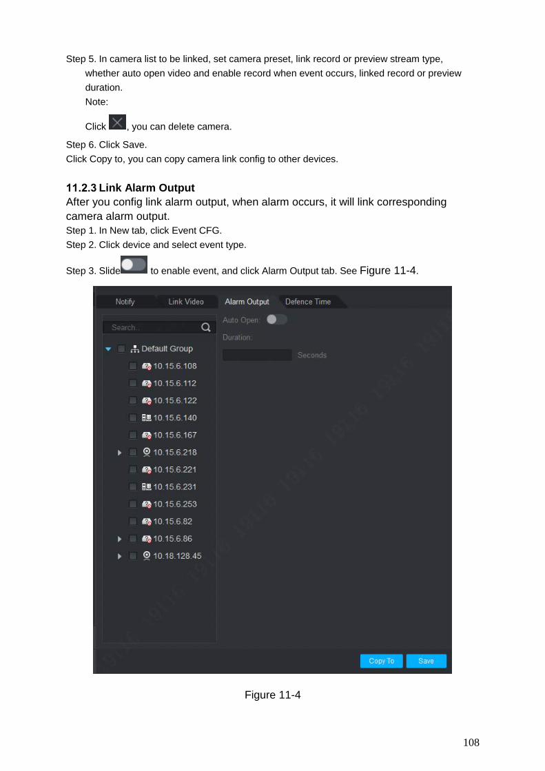
108
Step 5. In camera list to be linked, set camera preset, link record or preview stream type, whether auto open video and enable record when event occurs, linked record or preview duration. Note:
Click , you can delete camera.
Step 6. Click Save. Click Copy to, you can copy camera link config to other devices.
Link Alarm Output After you config link alarm output, when alarm occurs, it will link corresponding camera alarm output. Step 1. In New tab, click Event CFG. Step 2. Click device and select event type.
Step 3. Slide to enable event, and click Alarm Output tab. See Figure 11-4.
Figure 11-4

109
Step 4. Select alarm output of link camera and set whether to auto enable and duration. Step 5. Click Save. Click Copy to, you can copy camera link config to other devices.
Arm Time
Event is armed all-day by default. You can set arm time as needed. Step 1. In New tab, click Event CFG. Step 2. Click device and select event type.
Step 3. Slide to enable event and click Arm Time tab. See Figure 11-5.,
Figure 11-5
Step 4. In corresponding day of week drag mouse to delete to add arm time. You also can click
of each day of week to set arm time in pop-up box.
Step 5. Click Save.

110
Click Copy to, you can copy camera arm time config to other devices.
11.3 Event View You can view the alarm event information, disable event sounds or disable alarm linkage pop video, pause refresh of event information.
In homepage, click or in New tab, select the Event, see Figure 11-6.
In the Event interface you can view real-time alarm information, view up to 1000 latest messages, please search historical alarm message in log, see Ch 7.
Select event, you can check Disable sound to disable the alarm sound for event; check Stop link video popup to prohibit pop-up video; check Stop refresh to pause refresh of event.
Select event, click the Confirm, you can add a description to the event.
After you handle event or confirm event, you cannot change the status of the event.
Figure 11-6

111
12. Video Wall
12.1 Video Wall You can set video wall layout, live preview on wall, scheme and tour plus playback on wall. In New tab, click Video Wall, see Figure 12-1.
Figure 12-1
Serial number Task Note
1 Device list When set Default Device Tree to Device Tree (by device), the device tree displays device group and channels for the device.
When set Default Device Tree to Area Tree (by channel), the device tree displays device channels.
See Ch 8.
Preview Right click device channel and select Preview, display corresponding device channel in the Preview area.
Select window of video wall with bound device channel, in Window Details area>Operation column, click , corresponding video will be displayed in the video preview area.
Switch stream
You can switch stream through the following two ways.
Right click device channel and select stream type, and set

112
the desired stream. Select window with bound device channel, right click to select
stream type, and set the desired stream.
PTZ There are two ways you can enter PTZ control interface.
Click PTZ area, the system displays the PTZ control interface.
Select window with bound device channel, select the right to switch to the head, the system pop-up PTZ control interface.
See Ch 4.6.
2 Video wall Set video wall layout and channel video preview on the wall.
See Ch 12.2.
Scheme tour
Add scheme, set tour and enable tour.
See Ch 12.3.
3 Clear video source
Select window with bound device channel, right click to select Clear Video Source.
Bottom Select window with bound device channel, right click to select Bottom, to set the video wall to the bottom.
Set wall mode
Select window with bound device channel, right click to select Wall mode>Live or playback on wall, set video wall mode.
Open Audio
Select window with bound device channel, click at the upper right corner of the screen, to turn on audio.
Paste Click the window will occupy the physical screen of the window.
Maximize Click , the window will fill the window in the whole screen.
Close Click to close the window.
4 Window details
In Window Details area of the window you can view the channel information, set tour video channel time span and stream type, preview video channel, adjust order of video channels or delete unwanted video channel.
5 Set video wall layout Click to switch video wall
display layout.
6 Function bar
Click in the pop-up screen switch box, select screen on or off screen.
Click to refresh the screen information. Choose bound NVR device or device channel video wall in

113
group, click to open tour; click to close tout. Click to delete the selected window.
Click to clear the screen.
Click , you can select multiple windows, then the icon
changes to ; click a window.
Click to display window number and video wall number.
12.2 Config Favorites You shall place commonly used monitoring or linked channel to a same favorites for easy management and output. In device list, click Favorite tab, see Figure 12-2.
Figure 12-2
Add Favorite Step 1. In Video Wall interface, right click on favorite list and select Manage Favorite, see Figure
12-3.

114
Figure 12-3
Step 2. Click .See
Note: In Figure 12-2, you can click New Favorite, to open Figure 12-4.
Figure 12-4
Step 3. Enter name, click Save. Note: If you want to add more favorites, click Save and Continue to continue adding.
Step 4. Add channel to favorite, see Figure 12-5.

115
Figure 12-5
1. Select channel on organization tree. 2. Select favorite in favorite list. 3. Click to complete adding.
Step 5. Click of Manage Favorite interface to exit.
Delete Favorite
Step 1. In Video Wall interface, right click in Favorite area, and select Manage Favorite. See Figure 12-3.
Step 2. Select favorite, click next to it and delete.
Note: In Figure 12-2, you can click favorite you want to delete, and right click it.
Delete Channel
Step 1. In Video Wall interface, right click in Favorite area, see Figure 12-3. Step 2. Select favorite to delete.
Step 3. Select channel, click to delete channel.
Note:
In Figure 12-2, you can click of channel you want to delete, and select channel, right
click delete this item. Confirm your selection.
Change Favorite Name

116
In Figure 12-2, click favorite name you want to modify, right click Change Favorite Name, enter new name. Note: You cannot change name of default favorite.
12.3 Set Video Wall and Output Condition Decoder and video wall are connected successfully. Add encoder, see Ch 3. Step Step 1. Set video wall layout.
a) In video wall interface, click and in pop-up box click +. See Figure 12-6.
Note:
Select multiple screens, click to add splicing screen; select splicing screens, click to
cancel splicing screen; click to clear screen config.
Figure 12-6
b) In basic config interface, set video wall name, select Layout, and click in video wall, to add video wall layout.

117
c) Click Next. See Figure 12-7.
Figure 12-7
d) Drag decoder into slot, to bind decoder and screen. Note: Click screen display, to show screen no., click Hide number to hide screen number. If you want to cancel bound decoder slot, right click corresponding screen and select
Cancel. e) Check Apply Now to immediately use this config; click Finish to complete setup.
Note: Check Apply Now, then return to video wall interface to enable this config. Step 2. Preview channel video on wall.
a) In Video Wall interface, click layout you want, and slide , to enable video wall
layout. See Figure 12-8.
Note:
In pop up box, select video wall layout, click to modify video wall layout, click to delete
layout. See Figure 12-8.

118
Figure 12-8
b) Drag device channel into screen, bind channel and screen. Video of corresponding channel is played in the screen, and channel info will be show in Window Details area. Note: Via window split, you can enable window in screen. When the device supports roaming, you can drag window randomly among all
screens. When you drag NVR to the screen, then all channels of NVR are toured on video
wall. You can view tour window channel info in Window Details area. You can set tour channel time span and stream type and preview channel video in Operation column, adjust channel order or delete channel.
12.4 Scheme Tour on Video Wall Step 1. Add plan.
a) Select video wall layout and bind channel.
b) Click .See Figure 12-9.
Figure 12-9
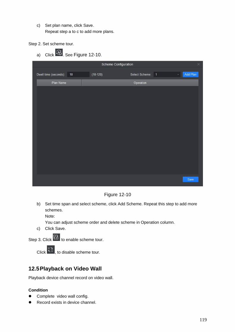
119
c) Set plan name, click Save. Repeat step a to c to add more plans.
Step 2. Set scheme tour.
a) Click . See Figure 12-10.
Figure 12-10
b) Set time span and select scheme, click Add Scheme. Repeat this step to add more schemes. Note: You can adjust scheme order and delete scheme in Operation column.
c) Click Save.
Step 3. Click to enable scheme tour.
Click , to disable scheme tour.
12.5 Playback on Video Wall Playback device channel record on video wall. Condition Complete video wall config. Record exists in device channel.
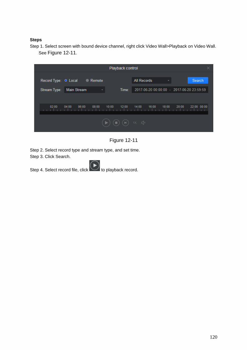
120
Steps Step 1. Select screen with bound device channel, right click Video Wall>Playback on Video Wall.
See Figure 12-11.
Figure 12-11
Step 2. Select record type and stream type, and set time. Step 3. Click Search.
Step 4. Select record file, click to playback record.

121
13. People Count You can search and export people count result, contrast by time and channel and export people count data. Condition Enabled people count function, see Ch 4.4.4. People count data exist in device. Steps Step 1. In New tab, click People Count. See Figure 13-1.
Figure 13-1
Step 2. Select channel with people count data, and set time and period for search. Note: You can search people count data by date, time, year or month. If you select multiple channel, then it will search data of these channels in search period
Step 3. Click Search. The system shows people count result in this period, see Figure 13-2.

122
Figure 13-2
Step 4. Contrast people count results.
a) Select statistical figure type, set filter to be ex Enter or Exit, and click to enable
contrast. See Figure 13-3.
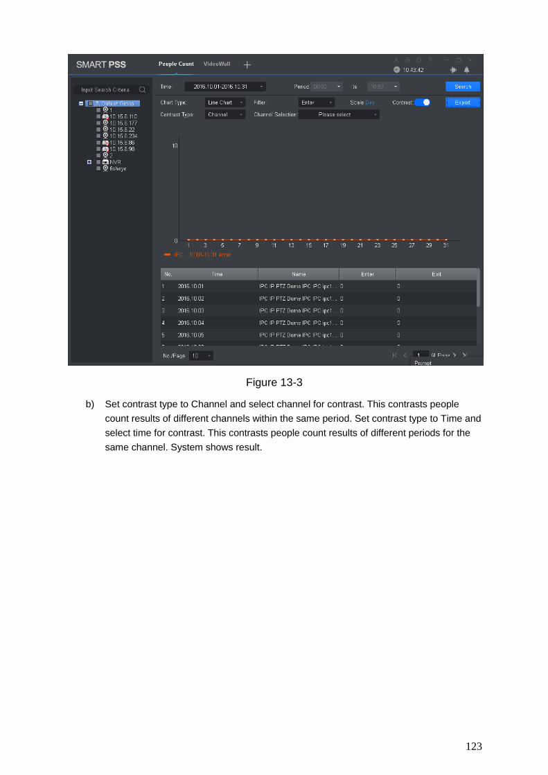
123
Figure 13-3
b) Set contrast type to Channel and select channel for contrast. This contrasts people count results of different channels within the same period. Set contrast type to Time and select time for contrast. This contrasts people count results of different periods for the same channel. System shows result.

124
14. Heat Map You can search object moving accumulated density in device monitor image. Condition Device has enabled heat map statistics. Heal map data exist in device. Steps Step 1. In New tab, click Heat Map. See Figure 14-1.
Figure 14-1
Step 2. Select camera with existing heat map data, and set search time and period.
Note: You can search heat map data by date, period, or day of week.
Step 3. Click Search. System shows object moving accumulated density result of this period monitored by device. Click Export to export heat map date.

125
15. PC-NVR After PC-NVR is added, you can manage disk, manage channel, set record plan and view version. Condition PC-NVR is installed and running now. See Ch 3 to add PV-NVR.
15.1 Disk Manager Step 1. In New tab, click PC-NVR. Step 2. Select HDD tab, see Figure 15-1.
Figure 15-1
Step 3. Select record plan when HDD is full, and set disk space, click Allocate. System pops up info box, click OK.
Warning: Re-allocate disk space, system will delete all record files on the disk, be careful!
15.2 Channel Management

126
Set channel info to pass PC-NVR record plan. Step 1. In New tab, click PC-NVR. Step 2. Select Channel Management tab, see Figure 15-2.
Figure 15-2
Step 3. In device list select device channel, click . System will add the selected
device channel to list on the right. Note:
Click to add device channel and shown in thumbnail, click to add device channel
and shown in list. If you delete unwanted device channel, check box in front of one device channel or
check Selected channel to select all channels, click to delete. Step 4. Click Save.
15.3 Set Record Plan For the selected channel, set record schedule, motion detect, alarm, MD& alarm, or smart record plan. Step 1. In New tab, click PC-NVR. Step 2. Select Record Plan tab. See Figure 15-3.

127
Figure 15-3
Step 3. Select channel to set record plan, select stream type, set pre-record time and delay
record time. Step 4. Check record type, and select record time in corresponding day of week bar.
Note:
You can click next to each day of week bar, and in pop-up box set record type and
period. Step 5. Click Save.
Note: Click Copy to, and check device channel, you can copy the record plan in this channel
to other device channel. Click Default to restore default status of device channel record plan.
15.4 Version Info You can view PC-NVR name, storage path and version. Step 1. In New tab, click PC-NVR. Step 2. Select Version tab, see Figure 15-4.

128
Figure 15-4
15.5 Modify Port
Step 1. Click at the lower-right corner of PC, select PC-NVR Setting. See Figure 15-5.
Figure 15-5

129
Step 2. Click and enter port no. you want.
If you slide to enable auto ON, after PC boots up, PC-NVR will be ON automatically.
Step 3. Click Save.
15.6 Modify Password
Step 1. Click at the lower-right corner of PC, select Password Setting. See Figure 15-6.
Figure 15-6
Step 2. Enter original password, and enter new password, confirm new password. Step 3. Click Save.

130
16. Video Talk SmartPSS supports intercom. It can connect to intercom device, for call, live preview, remote unlock, message sending and etc. The following is just an example. Note: Intercom device must be connected to LAN and configured ready. After fence station and VTO web interface are configured, you need to add to SmartPSS
Client, please refer to Ch 3.5 for steps to add device.
Click , in New Function interface, select Intercom to show intercom interface.
16.1 VTS Center Note: If it is the first time entering intercom interface, you will see a setup interface.
Step 1. Click . See Figure 16-1.
Figure 16-1
Step 2. Click . See Figure 16-2.
Figure 16-2
Step 3. Enter VTS address, click OK.
16.2 Monitor
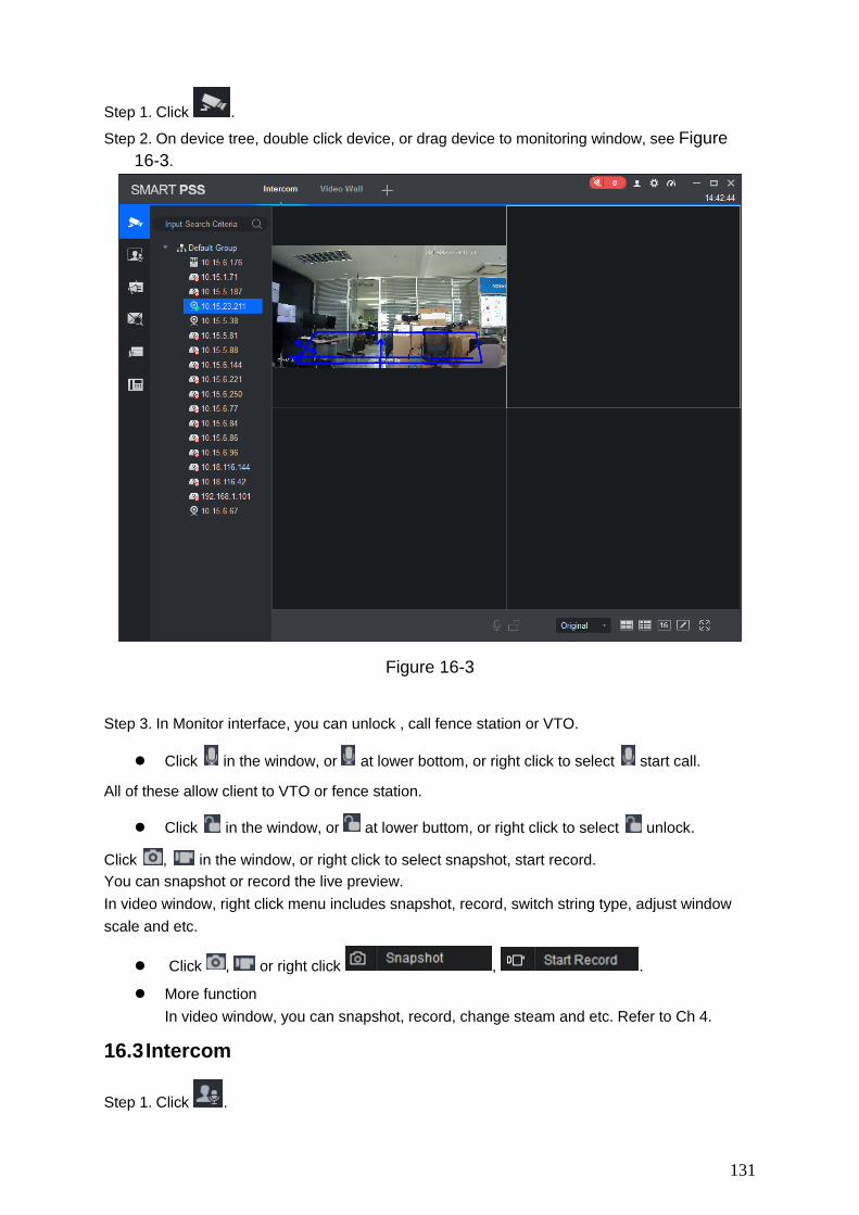
131
Step 1. Click .
Step 2. On device tree, double click device, or drag device to monitoring window, see Figure 16-3.
Figure 16-3
Step 3. In Monitor interface, you can unlock , call fence station or VTO.
Click in the window, or at lower bottom, or right click to select start call.
All of these allow client to VTO or fence station.
Click in the window, or at lower buttom, or right click to select unlock.
Click , in the window, or right click to select snapshot, start record. You can snapshot or record the live preview. In video window, right click menu includes snapshot, record, switch string type, adjust window scale and etc.
Click , or right click , .
More function In video window, you can snapshot, record, change steam and etc. Refer to Ch 4.
16.3 Intercom
Step 1. Click .

132
Step 2. Click device on device tree, see Figure 16-4. Note: According to info reported by fence station, or VTO, it will auto generate contact list.
By click next to Contact, you can quickly search contact. It
supports fuzzy search of building, unit, room.
Figure 16-4
Step 3. In Contacts interface, you can call VTO, VTH and etc.
If client needs to call VTO in a certain unit.
Step 1. Right click on VTO name card to call VTO. System pops up call box, see Figure 4-43.
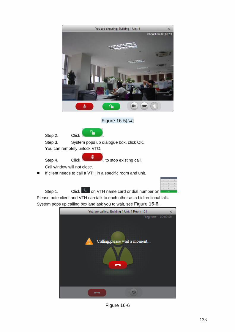
133
Figure 16-5[A4]
Step 2. Click . Step 3. System pops up dialogue box, click OK. You can remotely unlock VTO.
Step 4. Click , to stop existing call. Call window will not close.
If client needs to call a VTH in a specific room and unit.
Step 1. Click on VTH name card or dial number on . Please note client and VTH can talk to each other as a bidirectional talk. System pops up calling box and ask you to wait, see Figure 16-6 .
Figure 16-6

134
Step 2. When VTH picks up, client can talk with VTH. If VTH does not answer over 60s, then client pops up a box to ask if you want to dial again.
You can click to re-dial. If the VTH is busy or hang up call, client will ask you to try again later.
If VTO is calling client. Client pops up VTO call box, see Figure 16-8.
Figure 16-7
You can click to answer VTO call, and start a bidirectional talk.
You can click to unlock.
If VTH is calling client. Client pops up VTH call box, see Figure 16-9.
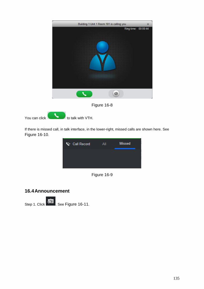
135
Figure 16-8
You can click to talk with VTH. If there is missed call, in talk interface, in the lower-right, missed calls are shown here. See Figure 16-10.
Figure 16-9
16.4 Announcement
Step 1. Click . See Figure 16-11.

136
Figure 16-10
Step 2. On device tree, select VTH and support multiple choices. Step 3. Enter message name and content, click Send. You can view announcement info on VTH.
Note: During sending, Send button is grey. You shall wait until it resumes before you can send message.
16.5 Search You can search alarm record, unlock record and call record. This chapter takes alarm record as an example.
Step 1. Click , select alarm record type. See Figure 16-12.

137
Figure 16-11
Step 2. Set criteria, click Search. You can export result of search.
16.6 Issue Card
Step 1. Click , see Figure 16-13.

138
Figure 16-12
Step 2. Create organization tree, see Figure 16-14.
Figure 16-13

139
1. In blank area of organization tree, right click and select Add Organization. See Figure 16-15.
Note: You also can click Sync Organization Tree to organization created when you add the device will be shown here.
Figure 16-14
2. Enter name. 3. Click the organization you just add, and right click and select Add Organization. 4. Enter name of unit, click Save. 5. Click node of device to link, right click to link device. See Figure 16-16.
Figure 16-15
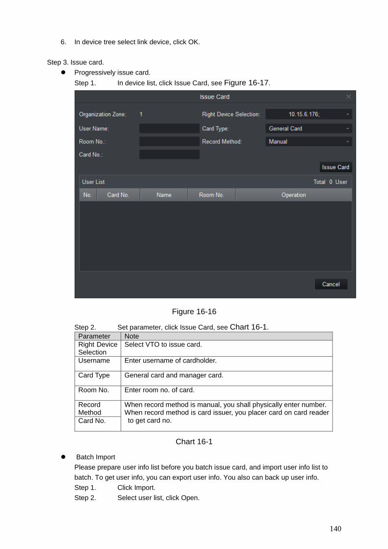
140
6. In device tree select link device, click OK. Step 3. Issue card.
Progressively issue card. Step 1. In device list, click Issue Card, see Figure 16-17.
Figure 16-16
Step 2. Set parameter, click Issue Card, see Chart 16-1. Parameter Note Right Device Selection
Select VTO to issue card.
Username Enter username of cardholder.
Card Type General card and manager card.
Room No. Enter room no. of card.
Record Method
When record method is manual, you shall physically enter number. When record method is card issuer, you placer card on card reader to get card no. Card No.
Chart 16-1
Batch Import Please prepare user info list before you batch issue card, and import user info list to batch. To get user info, you can export user info. You also can back up user info. Step 1. Click Import. Step 2. Select user list, click Open.

141
17. Access SmartPSS integrates access control device with effective management and configure of device. It achieves modularization of access business and integrates access with video link and e-map. Note:
Access controller must be added into SmartPSS client, please refer to device adding steps in Ch 3.
Access controllers are set on SmartPSS, including network, user management, time config and update. See Ch 10.
Click in New Function interface, select Access.
17.1 Console
Step 1. In Access interface, you can click See Figure 17-1.
Figure 17-1

142
No. Parameter Note
1 Organizations/Zones
Include organization tree or zone, right click in blank area to switch.
Organization tree has the following operations:
In organization tree blank area, right click to create group (same level with default group), switch organization tree or zone, sequence.
Right click group to create group (create group under selected group), rename group, open or close all, new map, delete group (exlcuing default group).
Right click access control device node to monitor, extract card info, sync data and reboot device.
Right click access control channel to support unlock, lock.
Global control has one-click NO/NC of all access control channels under emergency.
2 List/View List:Access status displsy and control.
View: Video/e-map preview and control.
3 Event View event:Access alarm event, normal event and abnormal event.
Chart 17-1
Organizations/Zones 17.1.1.1 E-Map E-map supports: Drag access control/video channel Set range of monitoring Set transparency of monitoring range. Add hot zone, max 3 levels of zones Re-edit map. See Ch 4.3. 17.1.1.2 Device Control 17.1.1.2.1 Access Control Device Right click access control device node, see Figure 17-2.
Figure 17-2

143
Parameter Note Monitor Real-time get device event info.
Details` Device details search, including device name, device IP, device type, and etc.
Extract Card Info Extract device card info and fingerprint info, export.
Sync Data Delete device info (excluding card record and alarm record), sync data in client to device. Data include right info, antipass back info, inter-lock and etc.
Show All Doors Info of all channels under access control device.
Reboot Device Reboot device.
Chart 17-2
17.1.1.2.2 Access Control Channel Control Right click access control channel, support the following operations, see Figure 17-3.
Figure 17-3
Parameter Note Open/Close Remotely open/close door
Rename Edit channel name
Door Config Config of door
Chart 17-3

144
Figure 17-4
Parameter Note Door Customize door name.
Reader X
Note:
X is a number.
1. Modify reader name.
2. Click or to switch in/out status.
Name reader and set status, the following is by default:
Single door one-way: 1 in 2 out. Dual door two-way: 1/3 in, 2/4 out. Four door one-way: 1/2/3/4 in
Status Normal, NO and NC
Unlock Hold Interval Unlock hold interval, 1s~600s。
Close Timeout Door close time out,1s~9999s。
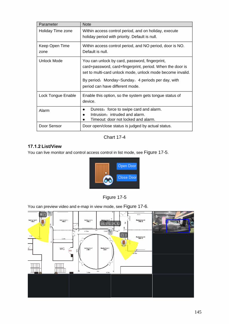
145
Parameter Note Holiday Time zone Within access control period, and on holiday, execute
holiday period with priority. Default is null.
Keep Open Time zone
Within access control period, and NO period, door is NO. Default is null.
Unlock Mode You can unlock by card, password, fingerprint, card+password, card+fingerprint, period. When the door is set to multi-card unlock mode, unlock mode become invalid.
By period:Monday~Sunday,4 periods per day, with period can have different mode.
Lock Tongue Enable Enable this option, so the system gets tongue status of device.
Alarm Duress:force to swipe card and alarm. Intrusion:intruded and alarm. Timeout: door not locked and alarm.
Door Sensor Door open/close status is judged by actual status.
Chart 17-4
List/View You can live monitor and control access control in list mode, see Figure 17-5.
Figure 17-5
You can preview video and e-map in view mode, see Figure 17-6.

146
Figure 17-6
Video preview: please refer to Ch 4.2. E-map preview: After you edit map, you can drag e-map into video window for preview.
Scroll your mouse to zoom in/out; click (or move mouse to range within camera) camera icon on mao to open video, right click access control on mao to enable/disable access.
Right click in e-map preview window, see Figure 4-64.
Figure 17-7
Parameter Note
Close Video Close current e-map window.
Close All Video Close all video windows.
Open All Channels Open all channels on e-map
Video Wall Output video channel in e-map to video wall.
Open All Doors Open all accesses on e-map
Full Screen Display current window in full screen
Chart 17-5
You can click to siwtch video format. The first three formats are standard
formats in your favorites, click to split interface, see Figure 17-8.
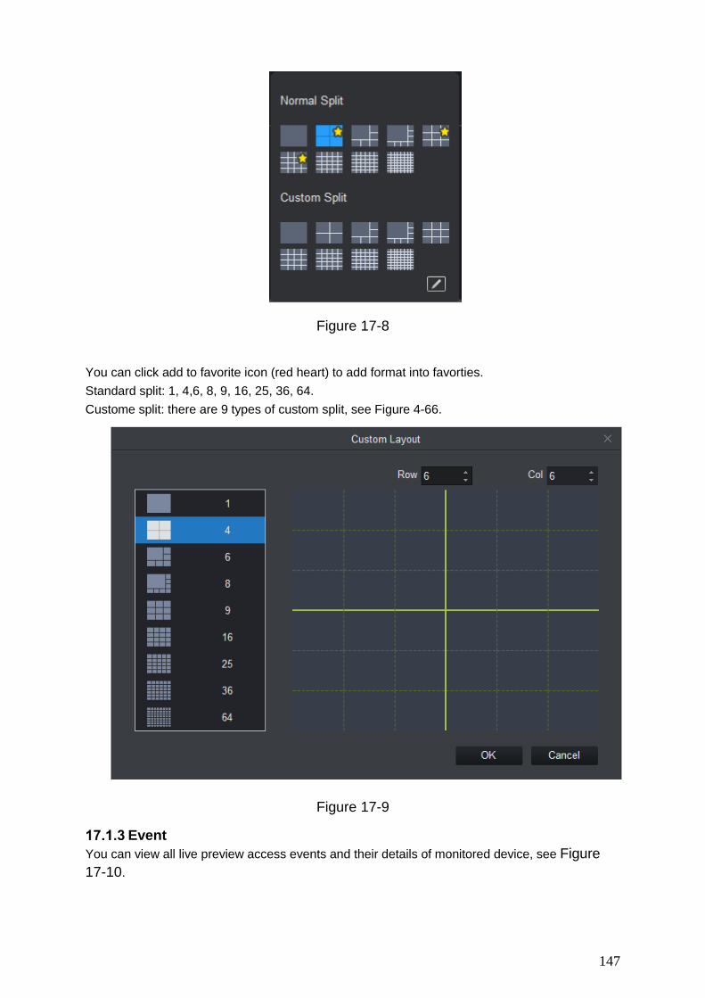
147
Figure 17-8
You can click add to favorite icon (red heart) to add format into favorties. Standard split: 1, 4,6, 8, 9, 16, 25, 36, 64. Custome split: there are 9 types of custom split, see Figure 4-66.
Figure 17-9
Event You can view all live preview access events and their details of monitored device, see Figure 17-10.

148
Figure 17-10
Parameter Note
Lock event in current event info, during the period the locked event will not be shown in list but user can search for it in log.
Clear event in current event info, not delete it from log.
17.2 User Management
In Access interface, you can click on the left to enter User Management interface, to manage all users. See Figure 17-11.

149
Figure 17-11
No. Parameter Note
1 Department Tree
Department management, support to add/delete/edit department organization and people count.
2 User Info User management, show corresponding user info under department node. Manage user and user card.
Sort user by user ID, card no., card type and department.
Department Management At department node or blank area in department tree, you can right click to operate, see Figure 17-12.
Figure 17-12
Parameter Note
Add Department Add department sub node or level 1 department node.
Name of departments at same level cannot be repeated.
Edit Department Edit department name.

150
Parameter Note
Delete Department Delete existing department.
You cannot delete department which contains user.
Search Department Support search of department node keyword
Chart 17-6
User Management 17.2.2.1 Set Card Type
In User Management interface, you can click button, select type of card you use, see
Figure 17-13. Warning: If card type and card reader do not match, then you cannot read card no.!
Figure 17-13
17.2.2.2 Add User 17.2.2.2.1 Add Single User

151
In User Management interface, click to manually add user info. User info incudes basic info,
fingerprint info details, see Figure 17-14, Figure 17-15 and Figure 17-16.
Figure 17-14
Figure 17-15
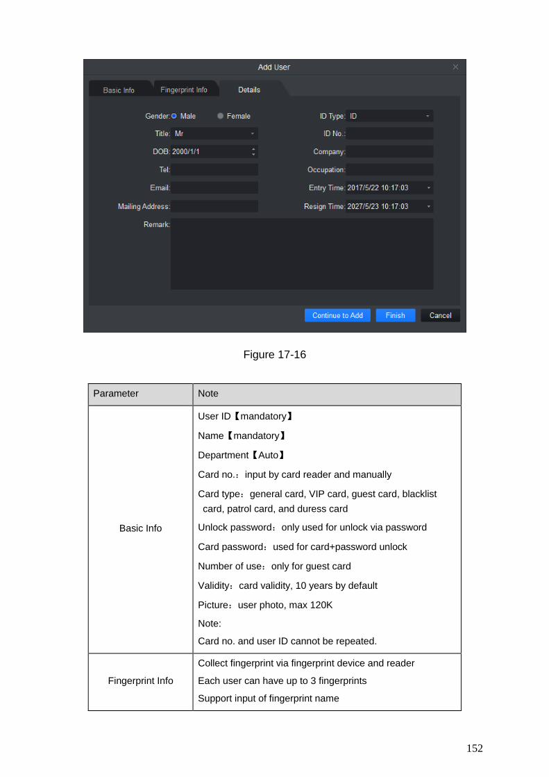
152
Figure 17-16
Parameter Note
Basic Info
User ID【mandatory】
Name【mandatory】
Department【Auto】
Card no.:input by card reader and manually
Card type:general card, VIP card, guest card, blacklist card, patrol card, and duress card
Unlock password:only used for unlock via password
Card password:used for card+password unlock
Number of use:only for guest card
Validity:card validity, 10 years by default
Picture:user photo, max 120K
Note:
Card no. and user ID cannot be repeated.
Fingerprint Info
Collect fingerprint via fingerprint device and reader
Each user can have up to 3 fingerprints
Support input of fingerprint name

153
Parameter Note
Details Gender, title, education and etc.
Chart 17-7
17.2.2.2.2 Batch Add
In User Management interface, you can click button to batch issue card, see Figure 17-17.
Figure 17-17

154
Parameter Note
Batch Issue Card by User
Manually check user to want to issue card to 【auto filter out users already have card】
Click Batch
User select card issuing device: support card issuer and card reader of controller.
Click read card no, and device starts to read.
Place card on device, link user to card no. one by one.
Click save to complete card issuing.
Batch Issue Card by User ID/Name
User click to batch issue card
Enable
User can enter user ID or name to fuzzy search.
Click to get user and auto complete adding user or directly click search to get first 200 unauthorized users. .
Click read card no., so device starts to read card no.
Place card on device one by one to link card to work ID by sequence.
Click save to complete.
Chart 17-8
In User Management, you can click button to edit user, see Figure 17-18.
Figure 17-18

155
Parameter Note
Department
Check user you want to edit.
Click .
Select new department.
Click OK.
Complete.
Validity
Check user you want to edit.
Click .
Check valid time.
Set time.
Modified valid time will be sent to device.
Complete.
17.2.2.2.3 Delete
In User Management interface, click button to delete user. Check user you want to delete,
click Delete. Confirm that all information and rights of the user you are doing to delete will be deleted from the device. 17.2.2.2.4 Import/Export Warning: If imported data (User ID/card no.) already exists, it will not import the information.
You can click either of or to import/export user info. Import/export info includes: user ID, name, card no., card type, department, fingerprint name, fingerprrint name. Note: During data importing, it auto generates department. 17.2.2.2.5 More Operations
In User Management interface, you can click .
Parameter Note
Modify user info.
Delete user info.

156
Parameter Note
Clear user card no. and delete card info in device.
Freeze card no. in device. You can click unfreeze if you want to restore frozen card.
Chart 17-9
In User Management interface, you can click to search keyword of user. Note: User ID and name suopport fuzzy search. Card no. supports accurate search.
17.3 Permission Management
In Access interface, you can click on the left to enter Permission Management which allows management of right about user issuing card.
Period Setup In Permission Management interface, click Period Setup to set specific reader to be valid with specific period and not valid on other periods, as well as set that user can only access a specific door within a specific period. Period is used for NO period, holiday period, first card period, remote verification period, door group right period.
Step 1. Click , select Period Setup. Step 2. Click Add, see Figure 17-19.

157
Figure 17-19
Step 3. Enter period name. Step 4. Select daily period for Monday to Sunday. Note: A device supports to 128 periods setup with daily limit of 4 periods.
Holiday Setup
In Permission Setup interface, click Holiday Setup to set different access period from general period.
Step 1. Click , select Holiday Setup. Step 2. Click Add, see Figure 17-20.

158
Figure 17-20
Step 3. Enter name. Step 4. Select range. Note: Within holiday period, holiday has priority in execution. Holiday period is for access only.
Door Group Right
In User Management interface, you can click , and set a specific period of time, a specific door or door group can be unlocked via verification, see Figure 17-21.

159
Figure 17-21
No. Parameter Note
1 Door Group Info Client door group info list
2 Door Group Details
Details of current door group
3 User Info User right info of current door group
Chart 17-10
In Door Group Right interface, click Add, see Figure 17-22.

160
Figure 17-22
Step 1. Enter name of door group, which cannot repeat existing door group name. Step 2. Select access period. Step 3. Check door, click Save.
Click button to re-edit door group info.
Wanring: Door group name cannot be repeated!
In Door Group Right interface, lcick to add use right, see Figure 17-23.

161
Figure 17-23
No. Parameter Note
1 User List Existing user info with door group right
2 Search List Info of user without door group right
Chart 17-11
Step 1. In search list dropdown list, select department of user you want to add or directly enter user ID or name.
Step 2. In search list check searched user and add to list. Step 3. You can delete user who already has right. Step 4. Click Save, to complete the selected user into all door groups. Note:

162
In search list filter out user who do not have card no. info.
In Door Group Right interface, you can click button to delete all information and right of the door group in the system. Warning: During right issuing process, please sure client and device are well connected.
User Right
In User Management interface, you can click in User Right interface to add specific user into
access right list, or delete specific user from list. Step 1. Check or cancel checked door group. Step 2. Click OK as to confrim cancellation or adding of personal user right.
First Card Unlock After you set first card unlock function, when everyday you are first user swipe card, you must pass that verification before you can unlock at access.
Step 1. Click , select First Card Unlock, see Figure 17-24.
Figure 17-24
Step 2. Click Add, see Figure 17-25.

163
Figure 17-25
Step 3. Select door, period, and status of first card. Status means status after you swipe card.
Step 4. In search list, search user by department, no. or name. Step 5. Check user. Step 6. Click Save.
Wanring: For user who is auto filtered out in search list due to lack of right of the door, he/she must be given right of this door by first card right holder.
Multi-door Lock
You can click Multi-door Lock to set that a specific door can be unlocked only when specific users of a group all pass verification in a specific order.
Step 1. Click , select Multi-door Lock. Step 2. Click User Group Manager, see Figure 17-26.

164
Figure 17-26
Step 3. In User Group Management interface, click , see Figure 17-27.

165
Figure 17-27
Step 4. Select group member. Step 5. Save to complete adding. Step 6. In Multi-door Unlock interface, click Add. Step 7. Select door you want to enable multi-door unlock. Step 8. In Multi-door unlock setup interface, check group. Step 9. Fill in valid number of user for each group. Step 10. Select unlock methof for each gourp. (card, password and fingerprint).
Step 11. Click to adjust sequence of unlock.
Step 12. Click Save. Note: A group can contains up to 64 users.

166
A door with enabled multi-card unlock supports up to 4 groups to verify at the same time, total number of user cannot exceed 64; total valid user cannot exceed 5.
Anti-pass Back
In Permission Management interface, click Anti-pass Back to set verification user. A user verifies at door A must verify at door A again when exits since card record must match one to one. If a user does not verify when enters, he/she will not pass verification when exits.
Step 1. Click , select Anti-pass Back. Step 2. You can click Add in Anti-pass Back interface. See Figure 17-28.
Figure 17-28
Step 3. Select access controller to use anti-pass back. Step 4. Select anti-pass back rule according to access controller. Step 5. Confirm. Note: Rule of anti-pass back: Unit/single door controller: door reader anti-pass back. Dual door controller/four door controller: reader 1 and 2 anti-pass back, reader 3 and 4 anti-pass back, reader 1/3 and 2/4 anti-pass back, reader 1 and 2/3/4 anti-pass back.

167
Four door controller: reader 1 and 2 anti-pass back, reader 3 and reader 4 anti-pass back, reader 1/3 and 2/4 anti-pass back, reader 1 and 2/3 anti-pass back, reader 1 and 2/3/4 anti-pass back.
Inter-door Lock In Permission Management interface, click Inter-door Lock, to set inter-lock between two doors on one access controller. When one door is unlocked, other doors will be locked. If you want to unlock one door (under normal status), all of the others shall be locked, otherwise you cannot unlock this door.
Step 1. Click , select Inter-door Lock. Step 2. You can click Add in Inter-door Lock interface. See Figure 17-29.
Figure 17-29
Step 3. Select access controller to inter-lock. Step 4. Select rule of inter-lock. Step 5. Confirm. Note: Role of inter-lock: Single door controller has no inter-lock. Dual door controller: 1-2 door inter-lock. Four door controller: 1-2 door inter-lock, 3-4 door inter-lock, 1-2-3 door inter-lock, 1-2-3-4 door inter-lock.
Remote Verification In Permission Management interface, you can click Remote Verification to ask the client to let user who passes verification enter within certain period, and admin will judge whether to unlock or not.
Step 1. Click , select Remote Verification.

168
Step 2. You can click Add in Remote Verification interface. See Figure 17-30.
Figure 17-30
Step 3. Select door and time to enable remote verification. Step 4. Save.
17.4 Event Configuration In Access interface, you can click Event Configuration. You can set that when a input point inside access system triggers a specific event, client will have video link(live preview/record), link event includes: alarm, abnormal, normal event, link event pop-up plus display in log. Please refer to the following for configuration of event scheme.
Step 1. Click . See Figure 17-31.

169
Figure 17-31
Step 2. Select device channel. Step 3. Select alarm event.
Event Type Description
Alarm Event
Chassis alarm:alarm triggered when card reader of the controller is forced to be removed.
Intrusion alarm:Excluding normal door open conditions, other door open conditions detected by door sensor 1
Duress alarm:Alarm triggered when door is opened by duress card (fingerprint).
Door left open alarm:door remained open exceeding set time
Blacklist alarm:Alarm triggered when door is opened via card on balcklist.
Abnormal Event Unauthorized or card lost: alarm triggered when the card
has no right to unlock this door or it has been reported lost.

170
Event Type Description
Card suspended:After the card is suspended, it cannot be used. Event is triggered at verification.
Unlock mode error:Event triggered when verification method and unlock method do not match.
Card validity error:Alarm is triggered when current time is not within card validity.
Period error:Alarm is triggered when verification of current period is not in access period.
Holiday unlock period error:Alarm is triggered when verification of current period is not in holiday period.
Incorrect first card:enable first card right, alarm is trigged when user unlock not using first card.
Inter-lock mode:Door with set inter-lock rule is unlocked, alarm it triggered when the other door is unlocked.
Anti-pass back mode: When one enters via verification but exits without verification, alarm is triggered at his/her next verification for entry.
Normal Event
Lock event:triggered when auto lock or door sensor detects door is locked
Card unlock:Triggered after passing card verification, door is unlocked
Fingerprint unlock:Triggered when door is unlocked after passing fingerprint verification.
Card + fingerprint unlock:Triggered when door is unlocked after passing card and fingerprint verification.
Card +password unlock:Triggered when door is unlocked after passing card and password verification.
Password unlock:Triggered when door is opened via password.
Button unlock:Triggered when door is opened via button.
Multi-card unlock:Triggered when the first card in multi-card unlock mode passes verification.
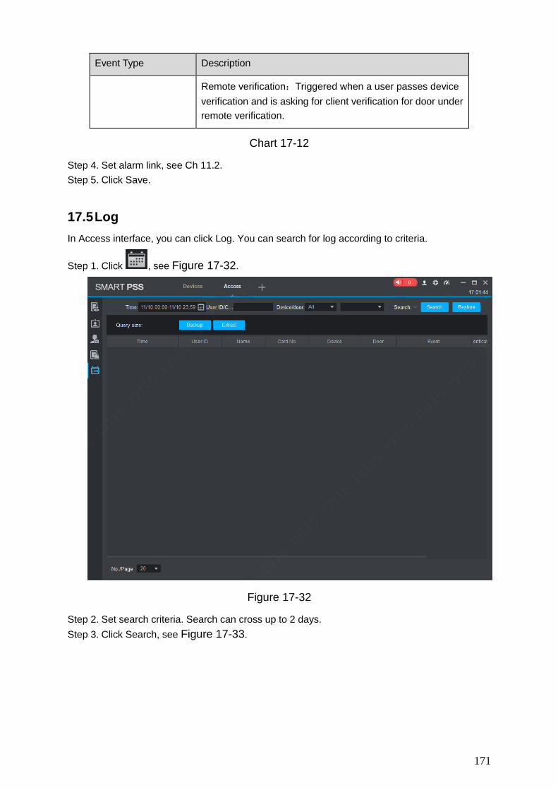
171
Event Type Description
Remote verification:Triggered when a user passes device verification and is asking for client verification for door under remote verification.
Chart 17-12
Step 4. Set alarm link, see Ch 11.2. Step 5. Click Save.
17.5 Log In Access interface, you can click Log. You can search for log according to criteria.
Step 1. Click , see Figure 17-32.
Figure 17-32
Step 2. Set search criteria. Search can cross up to 2 days. Step 3. Click Search, see Figure 17-33.

172
Figure 17-33
You can reset search criteria, export search result and view record.
, restore criteria.
, export searched log.
, extract log info of all devices or selected devices.
, view record.

173
18. Attendance It integrates time attendance, and effectively manage and configure devices to fulfill function of time attendance module.
Click , in New interface, select Attendance.
18.1 Console When you use access control device as time attendance, please set A&C device as time attendance in console. If it is paired with time attendance, then you can extract card info on time attendance.
ACS Attendance Node Setup
Step 1. Click . See Figure 18-1.
Figure 18-1
Step 2. Click , see

174
Figure 18-2
Step 3. Select A&C device, click OK. Setup is successful. Note: Via search function, you can quickly find device you want, fuzzy is supported. If you want to cancel attendance node, please click cancel a&c, click OK.
Extract Card Info In organization tree, right click designated time attendance and click Extract Card Info. The system will auto extract card info in the time attendance and show user info, including time, card no., no., name and etc.
18.2 User User includes department management, user management and right management.
Department/User Department management and user management functions of time attendance are the same with access module, as well as operations are the same. Info in these two modules can be shared, please see Ch 17.2.
Right

175
It manages user attendance right. 18.2.2.1 Enable Attendance Right You can enable attendance right of device.
Step 1. Click . See User interface.
Step 2. Click Access Control, see Figure 18-3.
Figure 18-3
Step 3. Click to enable edit.
Step 4. Select User. First select department, and then select user, see Figure 18-4. Search user by user ID or name, and select corresponding user, see Figure 18-5.

176
Figure 18-4
Figure 18-5
Step 5. In device tree, select time attendance. If you want to set more than one device, and to allow employees to sign up on any of these devices, please select more than one devices.
Step 6. Click Bind Device.

177
18.2.2.2 Disable Attendance Right
Step 1. Click . System shows User interface.
Step 2. Click Access Control, see Figure 18-3. Step 3. Select user, to view devices supporting sign up, see Figure 18-6.
Figure 18-6
Step 4. Click , to enable edit.
Step 5. Select user. First select department, and then select user, see Figure 18-4. Search user by user ID or name, and select corresponding user, see Figure 18-5.
Step 6. Select time attendance on device tree according to search result. Step 7. Click Cancel.
18.3 Set Attendance Set attendance period, shift and holiday.
Set Attendance Timezone Set timezone of attendance as attendance proof.
Step 1. Click and select Attendance Timezone. System shows Attendance Timezone interface.

178
Figure 18-7
Step 2. Click Add. System pops up New Timezone box, see Figure 18-8.
Figure 18-8
Step 3. Enter timezone name (used to identify timezone), click Save.
Step 4. Click behind timezone to set parameter, see Figure 18-9.

179
Figure 18-9
Parameter Note Time Zone Name
Customize period name.
Type Select work attendance type, including fix and free. Attendance type is set to fix attendance. For more info,
please see the rest of this chart. Attendance type is free attendance, and you only need
to set duration and whether to limit the latest sign in time.
Work Time Set work time of this period, meantime please select day of week.
If this period of attendance time zone has two separate sub periods, then you shall click to set second work time sign in/out time.
If you set two work time, then both time shall have sign in/out to be valid for normal attendance.
Record as X Workday
One week time is recorded as how many weekdays.
Start Sign In Time
Sign in only within set period on attendance device.
End Sign In Time Start Sign Out Time
Sign out only within set period on attendance device. End Sign Out
Time Late sign in within X minutes is permitted.
Define late, early leave and absence. You can set different time ranges, the followings are example only.
Set start time of work time has standard sign in time. Actual time later is than this time, within 5 min<X≤30min,will be late. Set start time of work time has standard sign in time. Actual time later is than this time, X>30min,will be absence. Set end time of work time has standard sign out time. Actual sign out is earlier than this time, and 0min<X ≤5min, will be early leave. Set end time of work time has standard sign out time. Actual sign out is earlier than this time, and 5min<X≤30min,will be absence. Set end time of work is standard off duty time. Actual sign out time later than this time, and over set value will be overtime.
Late sign in over X minutes is recorded as absence.
Early leave within X minutes is permitted. Early sign out over X minutes is recorded as absence. The sign out time that is X minutes later than off duty time is recorded as overtime.
Chart 18-1

180
Step 5. Click Save, to save time config. Note:
Edit attendance time zone: click next to attendance time zone to modify.
Delete attendance time zone: select attendance time zone, click Delete. You cannot delete period in progress. If you want to delete it, please go to attendance shift
interface and check all shifts to found those linked to the period in progress. If there are linked shifts, please cancel the link first.
Figure 18-10
Set Attendance Shift According to attendance time zone, set attendance shift, used for user shift.
Step 1. Click and select Attendance Shift. See Figure 18-11.
Figure 18-11
Step 2. Click Add. See Figure 18-12.
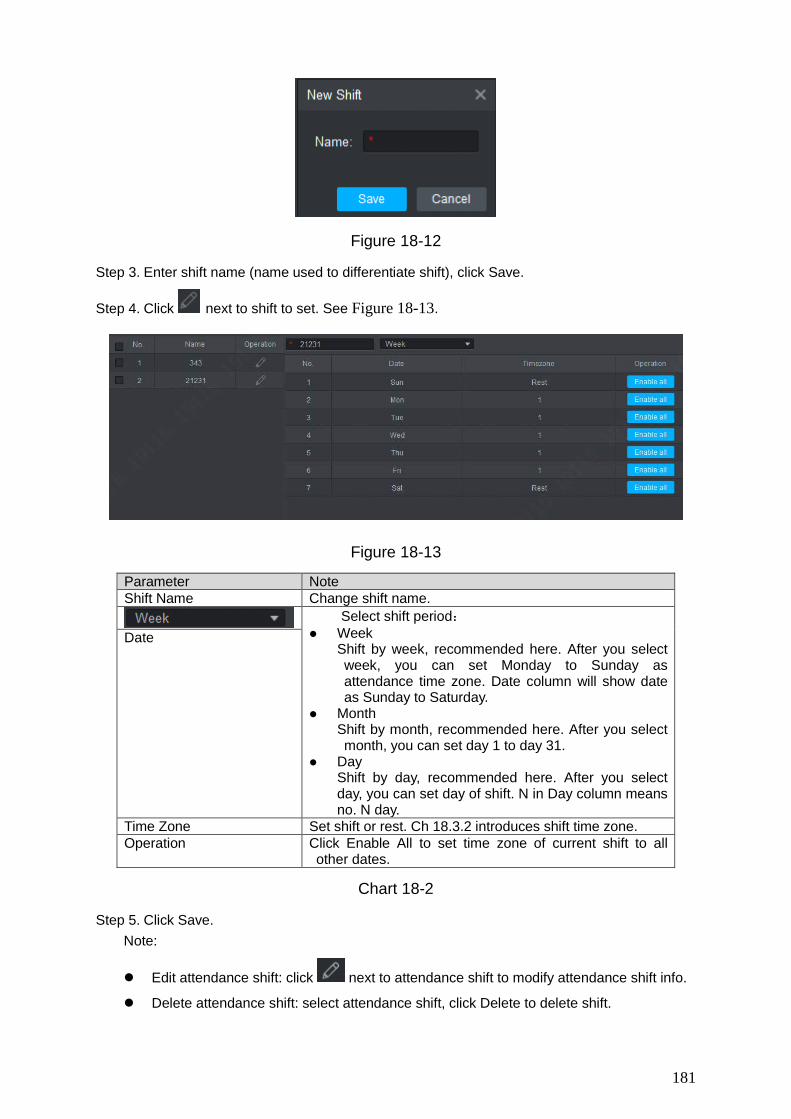
181
Figure 18-12
Step 3. Enter shift name (name used to differentiate shift), click Save.
Step 4. Click next to shift to set. See Figure 18-13.
Figure 18-13
Parameter Note Shift Name Change shift name.
Select shift period: Week
Shift by week, recommended here. After you select week, you can set Monday to Sunday as attendance time zone. Date column will show date as Sunday to Saturday.
Month Shift by month, recommended here. After you select month, you can set day 1 to day 31.
Day Shift by day, recommended here. After you select day, you can set day of shift. N in Day column means no. N day.
Date
Time Zone Set shift or rest. Ch 18.3.2 introduces shift time zone. Operation Click Enable All to set time zone of current shift to all
other dates.
Chart 18-2
Step 5. Click Save. Note:
Edit attendance shift: click next to attendance shift to modify attendance shift info.
Delete attendance shift: select attendance shift, click Delete to delete shift.

182
You cannot delete shift in progress. If you want to delete it, please go to attendance shift interface and check all shifts to found those linked to the shift in progress. If there are linked shifts, please cancel the link first.
Figure 18-14
Set Holiday If you have set a date to be holiday, so in general shift shall not set shift on this date, and you can set shift on this date via temporary shift.
Step 1. Click and select Holiday. See Figure 18-15.
z
Figure 18-15
Step 2. Click Add. See Figure 18-16.

183
Figure 18-16
Step 3. Set holiday parameter. Function Note Name Enter holiday name. Holiday Time Set holiday date. If holiday is more than one day, you only
need to set the first time.
Click to adjust date, select time, click OK. Holiday Length Set length of holiday.
Chart 18-3
Step 4. Click Save. Note:
Edit holiday: click next to holiday to modify holiday info.
Delete holiday: select holiday, click Delete to delete holiday.
Batch delete: select holiday ( is selected), click Delete.
18.4 Shift User shift has general shift and temporary shift.
General Shift According to attendance user need, set shift. Note: Edit existing user shift, steps are same with user shift.
Step 1. Click . See Figure 18-17.

184
Figure 18-17
Step 2. Select user. 1. Select department. System shows all users in this department.
Figure 18-18
2. Select user. See Figure 18-19.
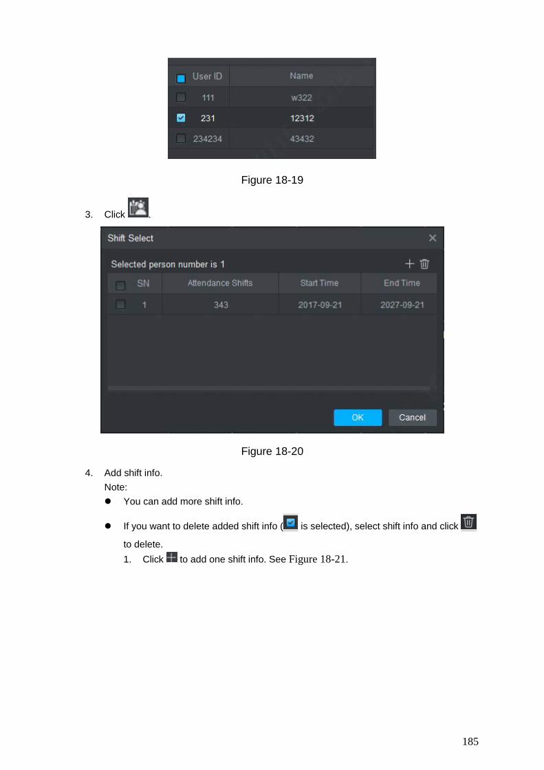
185
Figure 18-19
3. Click .
Figure 18-20
4. Add shift info. Note: You can add more shift info.
If you want to delete added shift info ( is selected), select shift info and click
to delete. 1. Click to add one shift info. See Figure 18-21.
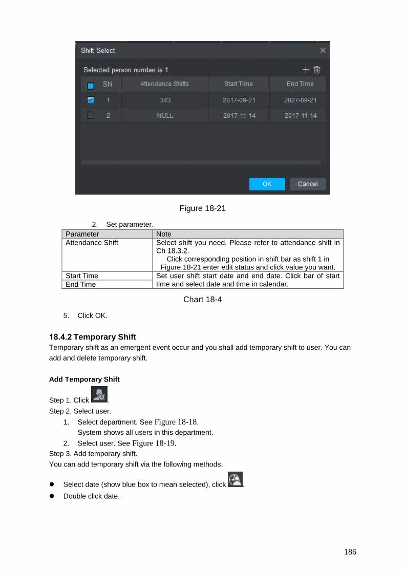
186
Figure 18-21
2. Set parameter. Parameter Note Attendance Shift Select shift you need. Please refer to attendance shift in
Ch 18.3.2. Click corresponding position in shift bar as shift 1 in
Figure 18-21 enter edit status and click value you want. Start Time Set user shift start date and end date. Click bar of start
time and select date and time in calendar. End Time
Chart 18-4
5. Click OK.
Temporary Shift Temporary shift as an emergent event occur and you shall add temporary shift to user. You can add and delete temporary shift. Add Temporary Shift
Step 1. Click . Step 2. Select user.
1. Select department. See Figure 18-18. System shows all users in this department.
2. Select user. See Figure 18-19. Step 3. Add temporary shift. You can add temporary shift via the following methods:
Select date (show blue box to mean selected), click . Double click date.

187
Figure 18-22
Step 4. Select timezone. Click OK Cancel Temporary Shift
Step 1. Click . Step 2. Select user.
1. Select department. See Figure 18-18. System shows all users in this department.
2. Select user. See Figure 18-19. Step 3. Cancel temporary shift.
You can cancel temporary shift via the following methods: Right click date with temporary shift, select Cancel temporary shift to cancel temporary
shift.
Select date with temporary shift (blue box means selected), click . Confirm to cancel.
Note: Blue “T” in calendar means that this date has temporary shift.
Set Default Shift for New User
After you set default shift for new user, when a user is added, he/she has this shift by default. Note: Repeat the following steps to link default shift to more than one department.
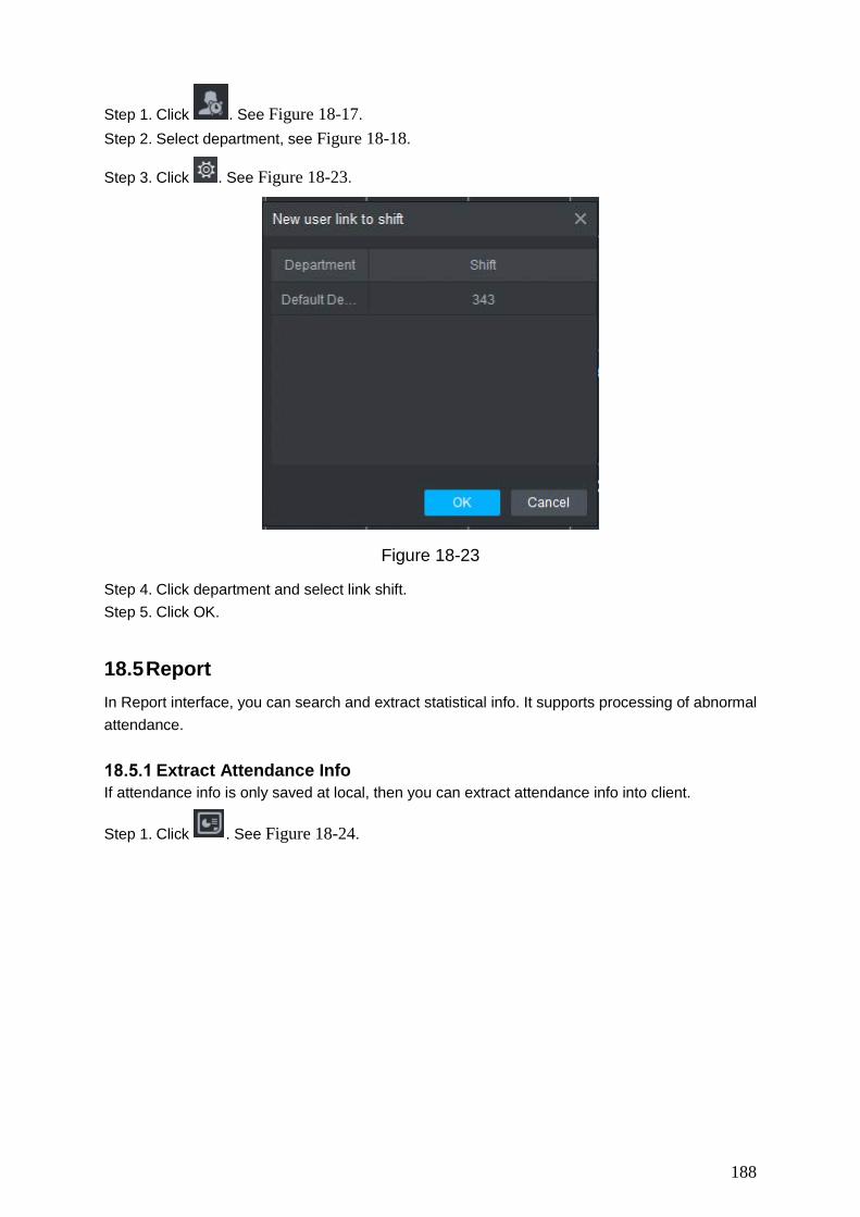
188
Step 1. Click . See Figure 18-17. Step 2. Select department, see Figure 18-18.
Step 3. Click . See Figure 18-23.
Figure 18-23
Step 4. Click department and select link shift. Step 5. Click OK.
18.5 Report In Report interface, you can search and extract statistical info. It supports processing of abnormal attendance.
Extract Attendance Info If attendance info is only saved at local, then you can extract attendance info into client.
Step 1. Click . See Figure 18-24.
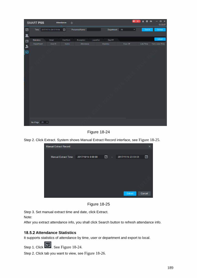
189
Figure 18-24
Step 2. Click Extract. System shows Manual Extract Record interface, see Figure 18-25.
Figure 18-25
Step 3. Set manual extract time and date, click Extract. Note: After you extract attendance info, you shall click Search button to refresh attendance info.
Attendance Statistics It supports statistics of attendance by time, user or department and export to local.
Step 1. Click . See Figure 18-24.
Step 2. Click tab you want to view, see Figure 18-26.
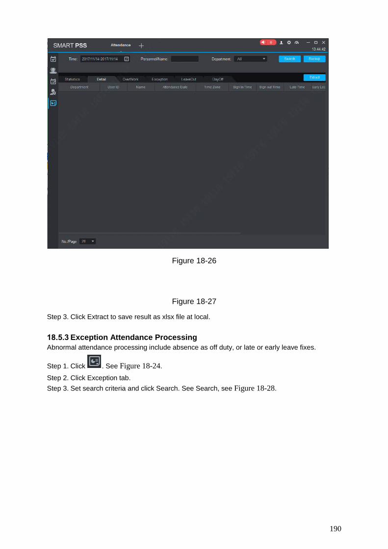
190
Figure 18-26
Figure 18-27
Step 3. Click Extract to save result as xlsx file at local.
Exception Attendance Processing Abnormal attendance processing include absence as off duty, or late or early leave fixes.
Step 1. Click . See Figure 18-24.
Step 2. Click Exception tab. Step 3. Set search criteria and click Search. See Search, see Figure 18-28.
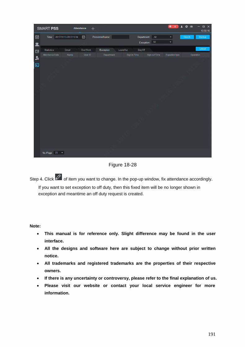
191
Figure 18-28
Step 4. Click of item you want to change. In the pop-up window, fix attendance accordingly.
If you want to set exception to off duty, then this fixed item will be no longer shown in exception and meantime an off duty request is created.
Note:
• This manual is for reference only. Slight difference may be found in the user interface.
• All the designs and software here are subject to change without prior written notice.
• All trademarks and registered trademarks are the properties of their respective owners.
• If there is any uncertainty or controversy, please refer to the final explanation of us. • Please visit our website or contact your local service engineer for more
information.