smart wires demo march 17, 2004 revisedelectricityconference/2004/divan.pdf · • the transmission...
TRANSCRIPT
Smart Wires
Distributed Intelligent Power Networks – A New Concept for Improving T&D System Utilization and Performance
T&D WorkshopCMU – Dec 15-16, 2004
Prof Deepak Divan (Georgia Tech) [email protected]
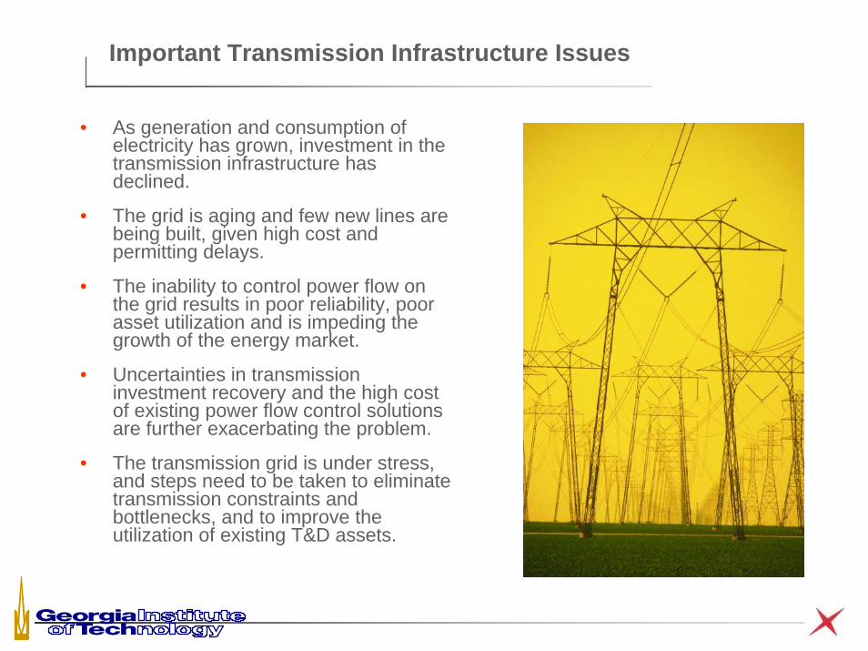
Important Transmission Infrastructure Issues
• As generation and consumption of electricity has grown, investment in the transmission infrastructure has declined.
• The grid is aging and few new lines are being built, given high cost and permitting delays.
• The inability to control power flow on the grid results in poor reliability, poor asset utilization and is impeding the growth of the energy market.
• Uncertainties in transmission investment recovery and the high cost of existing power flow control solutions are further exacerbating the problem.
• The transmission grid is under stress, and steps need to be taken to eliminate transmission constraints and bottlenecks, and to improve the utilization of existing T&D assets.
Other Factors Limiting T&D Infrastructure Development
The overall factors that govern our ability to act are complex and multi-dimensional.
• Public policy that is stalled in political wrangling;
• Semi-regulated Balkanized utility industry;
• Differing state regulations;
• Lack of uniform guidelines on valuing financial impact of reliability, capacity and congestion;
• External impacts and lumpiness of transmission investments;
• Centralized and aging technology architecture and legacy infrastructure;
• Energy markets based on the use of the T&D infrastructure as an ‘energy super-highway’;
• Rights of way, NIMBY and environmental issues;
For any business, it is critical that existing assets be efficiently utilized. This is not the case in the T&D world.

KCL, KVL and Ohms Law !!
• The distribution of current in a meshed network is governed by ‘Ohms Law’ – not ‘Contract Law’.
• In such a network, the first line that becomes ‘congested’, limits the capacity of all the interconnected lines on the network.
• Operation under (N-1) contingency conditions, further erodes available system capacity.
• Another unintended consequence of KCL and KVL are ‘loop flows’ that limit line capacity, resulting in loss of potential revenue.
• As demand increases, these factors can result in transmission loading relief calls, gaming, curtailed service and poor system reliability – even as critical assets (the power lines) remain significantly under-utilized.
Ability to control power flow on the grid is critical for improving reliability, asset utilization, and for enabling the energy market
j16 Ω
j24 Ω
138kV∠0°
138kV∠7.75°675A
450A

Power Grid Control Through FACTS
• Conventional technology for controlling power flow – Flexible AC Transmission Systems (FACTS). Typical FACTS devices can operate at up to 345 kV and can be rated as high as 200 MVA.
• Even though FACTS technology is technically proven, it has not seen widespread commercial acceptance due to a number of reasons.
– High total cost of ownership. The Marcy Convertible Static Compensator (CSC) cost $54 million - deploying a large number of similar systems could be prohibitively expensive.
– High fault currents (60,000 Amps) and high voltage levels (1000 kV) stress the power electronics system, making implementation of FACTS systems, in particular series connected devices, very difficult and expensive.
– Single point of failure yields reliability of 94%, significantly lower than the 99.99% reliability that is typical for the utility system itself.
– Highly customized design of FACTS devices requires skilled work force in the field to maintain and operate the system, not within a utility’s core competency normally. This leads to high MTTR and high cost.
Distributed Intelligent Networks – A New Paradigm
• One of the key driving factors in the modernization of the IT industry was the advent of massively distributed intelligent networks.
• Rapid advances in, and commoditization of microelectronics, computing and communication technologies have disrupted the established technology of centralized switches and copper wires.
• Distributed solutions can realize higher performance and higher reliability at lower cost –
– Use of commoditized mass-produced building blocks networked together to realize higher performance at lower cost.
– Massive redundancy, coupled with self-organizing and self-healing properties to realize high system reliability and availability.
– System can be implemented incrementally with full backward compatibility, and can be upgraded as technology or customer needs change
• A truly distributed approach to power networks may realize significant operational, economic and societal benefits

I-Grid – A Distributed Power Monitoring Sensor Network
ISP
ISPWAN
Provider
DATA IN
GESTO
R
DYNAMICREAL-TIMEDATABASE
STATICDATABASE
WEBACCESS
FLEXIBLENOTIFI-CATIONENGINE
OTHERDATABASES DATA
EXPORT
INTERNETOR
INTRANET
WIRELESSCONNECT
I-GRID PLATFORMREMOTEMONITORS
REMOTEUSERS
WEB BROWSER
NOTIFICATIONUTILITY STAFF& CUSTOMERS
END-USERREPORTS
INTERNET
2000 sensors across the US
Courtesy: Soft Switching Technologies
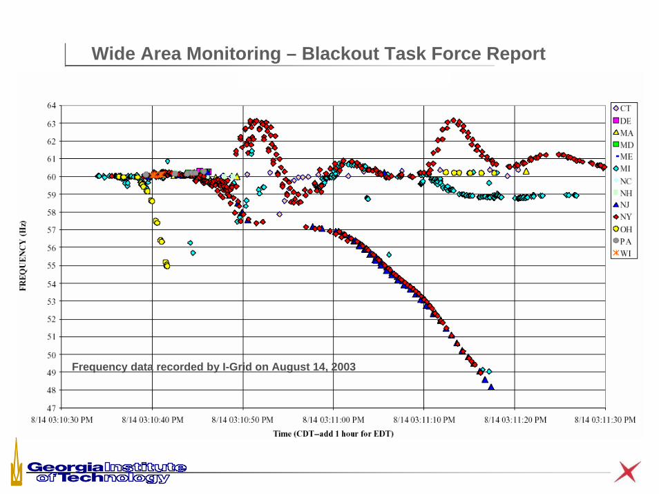
Wide Area Monitoring – Blackout Task Force Report
Frequency data recorded by I-Grid on August 14, 2003
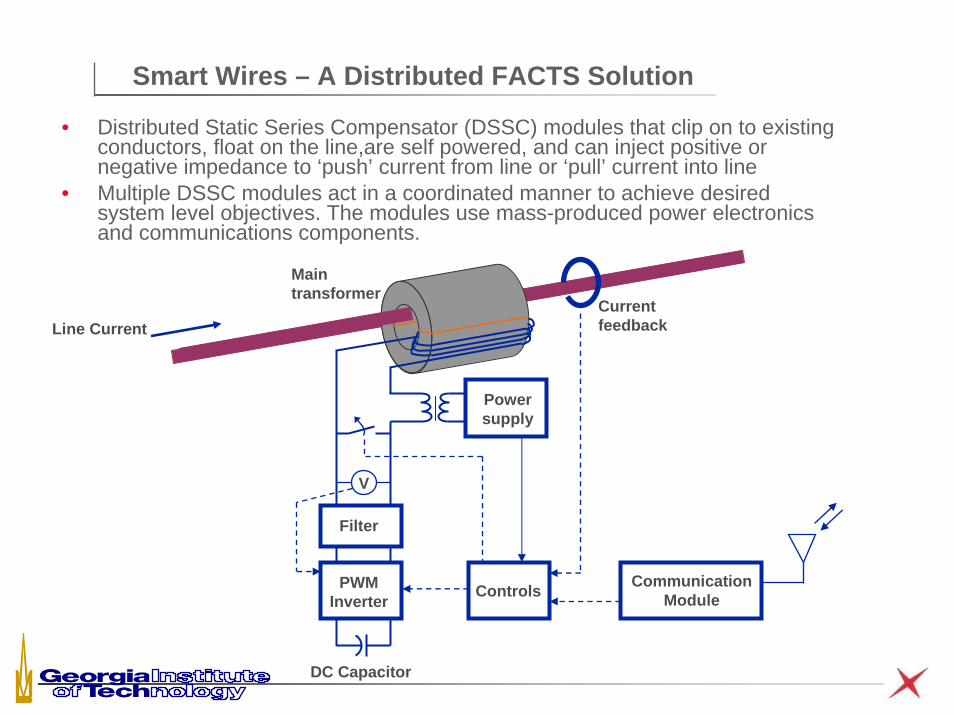
Smart Wires – A Distributed FACTS Solution
• Distributed Static Series Compensator (DSSC) modules that clip on to existing conductors, float on the line,are self powered, and can inject positive or negative impedance to ‘push’ current from line or ‘pull’ current into line
• Multiple DSSC modules act in a coordinated manner to achieve desired system level objectives. The modules use mass-produced power electronics and communications components.
Power supply
Main transformer
Filter
PWMInverter
DC Capacitor
V
Controls CommunicationModule
Current feedbackLine Current
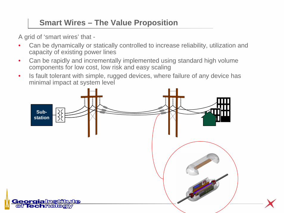
Smart Wires – The Value PropositionA grid of ‘smart wires’ that -• Can be dynamically or statically controlled to increase reliability, utilization and
capacity of existing power lines• Can be rapidly and incrementally implemented using standard high volume
components for low cost, low risk and easy scaling• Is fault tolerant with simple, rugged devices, where failure of any device has
minimal impact at system level
Sub-station
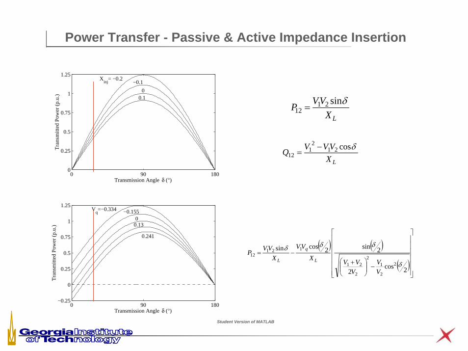
Power Transfer - Passive & Active Impedance Insertion
0 90 1800
0.25
0.5
0.75
1
1.25X
inj= −0.2
−0.1
00.1
Transmission Angle δ (°)
Tra
nsm
itted
Pow
er (
p.u.
)
0 90 180−0.25
0
0.25
0.5
0.75
1
1.25V
q=−0.334 −0.155
00.13
0.241
Transmission Angle δ (°)
Tra
nsm
itted
Pow
er (
p.u.
)
LXVVP δsin21
12 =
LXVVVQ δcos21
21
12−
=
( ) ( )( )
⎥⎥⎥⎥⎥⎥
⎦
⎤
⎢⎢⎢⎢⎢⎢
⎣
⎡
−⎟⎟⎠
⎞⎜⎜⎝
⎛ +−=
2cos2
2sin2cossin
2
2
12
2
21
12112
δ
δδδ
VV
VVVX
VV
XVVP
L
q
L
Student Version of MATLAB
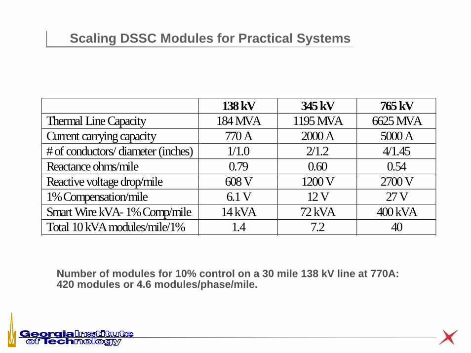
Scaling DSSC Modules for Practical Systems
138 kV 345 kV 765 kV Thermal Line Capacity 184 MVA 1195 MVA 6625 MVA Current carrying capacity 770 A 2000 A 5000 A # of conductors/ diameter (inches) 1/1.0 2/1.2 4/1.45 Reactance ohms/mile 0.79 0.60 0.54 Reactive voltage drop/mile 608 V 1200 V 2700 V 1% Compensation/mile 6.1 V 12 V 27 V Smart Wire kVA- 1% Comp/mile 14 kVA 72 kVA 400 kVA Total 10 kVA modules/mile/1% 1.4 7.2 40
Number of modules for 10% control on a 30 mile 138 kV line at 770A: 420 modules or 4.6 modules/phase/mile.
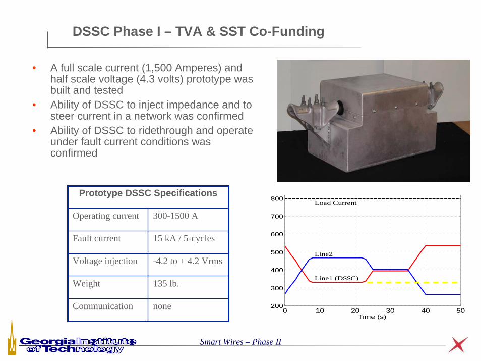
DSSC Phase I – TVA & SST Co-Funding
• A full scale current (1,500 Amperes) and half scale voltage (4.3 volts) prototype was built and tested
• Ability of DSSC to inject impedance and to steer current in a network was confirmed
• Ability of DSSC to ridethrough and operate under fault current conditions was confirmed
0 10 20 30 40 50200
300
400
500
600
700
800
Time (s)
Line2
Line1 (DSSC)
Load CurrentPrototype DSSC Specifications
Operating current 300-1500 A
Fault current 15 kA / 5-cycles
Voltage injection -4.2 to + 4.2 Vrms
Weight 135 lb.
Communication none
Smart Wires – Phase II
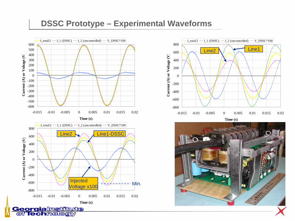
DSSC Prototype – Experimental Waveforms
-600-500-400-300-200-100
0100200300400500600
-0.015 -0.01 -0.005 0 0.005 0.01 0.015 0.02
Time (s)
Cur
rent
(A) o
r V
olta
ge (V
)
I_total/2 I_1 (DSSC) I_2 (uncontrolled) V_DSSC*100
-800
-600
-400
-200
0
200
400
600
800
-0.015 -0.01 -0.005 0 0.005 0.01 0.015 0.02
Time (s)
Cur
rent
(A) o
r V
olta
ge (V
)
I_total/2 I_1 (DSSC) I_2 (uncontrolled) V_DSSC*100
Line2 Line1
-800
-600
-400
-200
0
200
400
600
800
-0.015 -0.01 -0.005 0 0.005 0.01 0.015 0.02
Time (s)
Cur
rent
(A) o
r V
olta
ge (V
)
I_total/2 I_1 (DSSC) I_2 (uncontrolled) V_DSSC*100
Line1-DSSCLine2
Injected Voltage x100 Min.
(a)(b) (c)
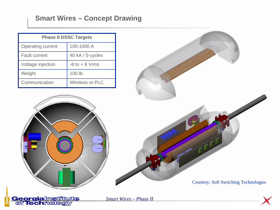
Smart Wires – Concept Drawing
Smart Wires – Phase II
Phase II DSSC Targets
Operating current 100-1000 A
Fault current 40 kA / 5-cycles
Voltage injection -8 to + 8 Vrms
Weight 100 lb.
Communication Wireless or PLC
Courtesy: Soft Switching Technologies
DSSC Impact on Power System
j16 Ω
j24 Ω
138kV∠0°
138kV∠7.75°675A
450A
j16 Ω
j24 Ω
138kV∠0°
138kV∠9.31°
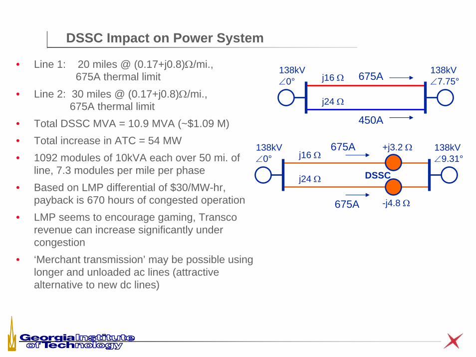
• Line 1: 20 miles @ (0.17+j0.8)Ω/mi., 675A thermal limit
• Line 2: 30 miles @ (0.17+j0.8)Ω/mi., 675A thermal limit
• Total DSSC MVA = 10.9 MVA (~$1.09 M)• Total increase in ATC = 54 MW• 1092 modules of 10kVA each over 50 mi. of
line, 7.3 modules per mile per phase• Based on LMP differential of $30/MW-hr,
payback is 670 hours of congested operation• LMP seems to encourage gaming, Transco
revenue can increase significantly under congestion
• ‘Merchant transmission’ may be possible using longer and unloaded ac lines (attractive alternative to new dc lines)
675A
675A
DSSC
+j3.2 Ω
-j4.8 Ω
DSSC Operational Capabilities
• Ability to increase or decrease steady state line current autonomously or under system controller command
• Ability to respond autonomously in case of fast transients or communications channel failure
• Ability to monitor actual conductor temperature and manually or automatically limit current as a function of conductor temperature
• High system reliability due to massive redundancy, single unit failure has negligible impact on system performance
• Zero footprint solution• Robust and rugged under typical fault conditions• Can be used with conventional or advanced conductors• Mass produced modules can be stocked on the shelf and repaired in factory
– does not require skilled staff on site• Easy and rapid installation (may be possible on live line)

Utility/Transco Benefits
A distributed Smart Wires system provides a totally unique approach to controlling power flow on new and existing power lines.
For transco and utility customers, Smart Wires can
•Enhance system reliability and capacity when considering (N-1) contingencies
•Provide additional revenue opportunities through congestion charges
•Divert current to other lines when a line is congested or overloaded thus improving reliability
•Allow current to flow along contract paths so energy contracts can be executed
•Increase dynamic and steady state capacity of transmission lines
•Prevent overload of T&D infrastructure as new generation is added

DSSC - Societal Benefits
• Improves reliability of the power grid• Enables energy market and enhances competition, potentially reducing energy
cost for end customers• Improves flexibility for locating new generation• Can create a new option for ‘merchant transmission’ using under-utilized ac lines• Improves return on capital employed -
– Enhances asset utilization, – Reduces trapped capital, – Defer new line construction,– Reduce lumpiness of investments,– Allows rapid implementation
• Zero footprint solution is environmentally friendly• Utilizes and enhances existing infrastructure (no stranded asset issues)• Makes the grid smart and controllable, allowing for growth & modernization• Solution has low technology risk

DSSC - Summary
• New approach for realizing a Distributed Static Series Compensator (DSSC) for use on transmission and sub-transmission systems
• Massively dispersed sensor, converter and actuator networks can provide low-cost, high reliability, scalability and fast deployment
• DSSC modules use conductor clip-on power electronics converters that float electrically and mechanically on a power line and control the line impedance
• DSSC modules are insensitive to line voltage and use high-volume components, thus potentially realizing much lower cost
• Prototype was designed, built and tested• Ability to change line impedance was
demonstrated, as was the ability to steer line currents in a network
• The DSSC represents the first of a family of Distributed FACTS or D-FACTS devices
Distributed Intelligent Power Networks
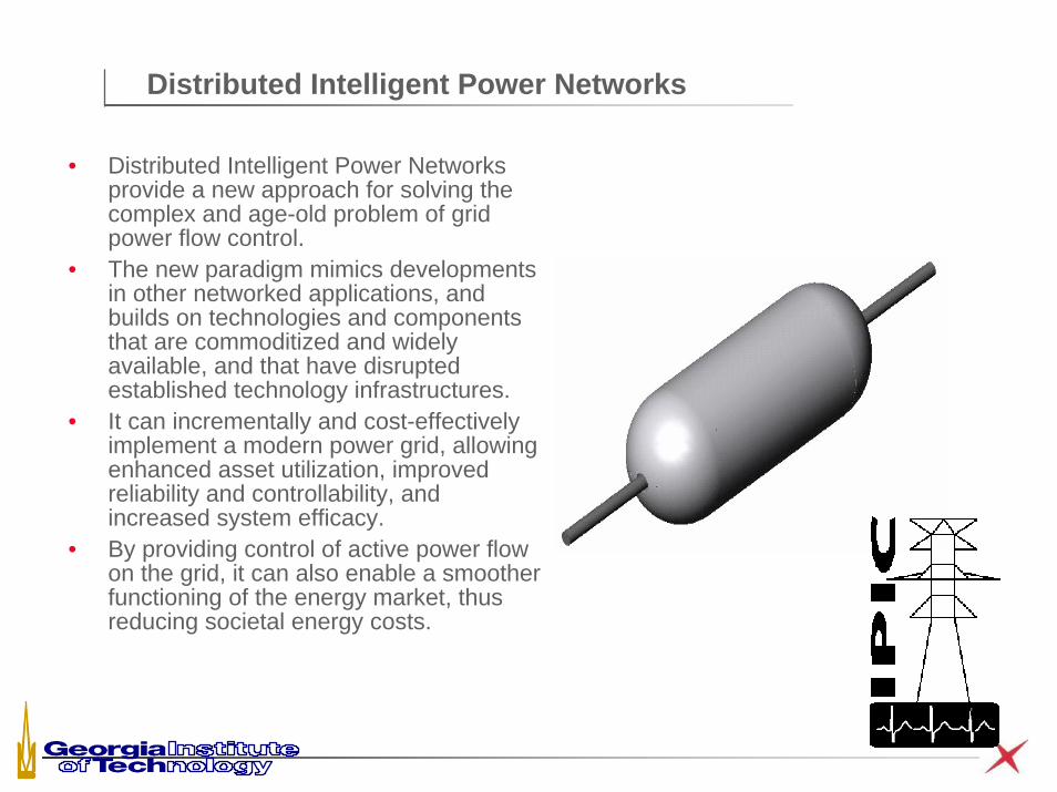
• Distributed Intelligent Power Networks provide a new approach for solving the complex and age-old problem of grid power flow control.
• The new paradigm mimics developments in other networked applications, and builds on technologies and components that are commoditized and widely available, and that have disrupted established technology infrastructures.
• It can incrementally and cost-effectively implement a modern power grid, allowing enhanced asset utilization, improved reliability and controllability, and increased system efficacy.
• By providing control of active power flow on the grid, it can also enable a smoother functioning of the energy market, thus reducing societal energy costs.