smartmove installation guidesmhelp.smartmovetaxis.com/wp-content/uploads/2014/03/smartmove... · 1x...
TRANSCRIPT

INSTALLATION GUIDE Version: 3.6
STEP SUMMARY PAGE 1 Fit mounting bracket 6
2 Fit column mount 6
3 Position junction box 7
4 Fit cables 7
5 Connecting the meter (OPTIONAL) 9
5a Schmidt Gx meter 9
5b Schmidt Gx meter with EFTPOS terminal 10
5c Martin Mkx meter 11
5d Martin Mkx meter with EFTPOS terminal 12
5e Novax Leda meter 13
5f Novax Leda meter with EFTPOS terminal 15
6 Fit GPRS antenna 16
7 Connect screen and power 17
8 Configure SmartMove 17
9 Test SmartMove 18
Head Office 147 Henley Beach Rd Mile End, South Australia 5031 Ph (08) 8238 0375 Fax (08) 8238 0391

SMARTMOVE Installation Guide
Version: 3.4 February 2009, Printed: 30 November 2010 Page 2
Schematic
Figure 1: Basic Wiring Schematic
Note 1: If the Fleet wishes to connect a meter to SmartMove or if an EFTPOS Terminal is already
connected to the meter, please refer to Step 5 and find the appropriate meter brand.

SMARTMOVE Installation Guide
Version: 3.4 February 2009, Printed: 30 November 2010 Page 3
Equipment Checklist
The SmartMove system consists of:
Components:
1x WaveOn screen and computer
1x GPS (Global Positioning System) Antenna
1x GPRS Antenna
1x Panic Switch
Power diode
1 x Fuse

SMARTMOVE Installation Guide
Version: 3.4 February 2009, Printed: 30 November 2010 Page 4
1x Junction box
Mount:
1x RAM-Mount
2x 56mm nut and bolt (secures RAM-Mount to plate)
1x WaveOn mounting plate
4x Plate screws (secures mounting plate to rear of WaveOn)
Cables:
1x12V battery lead running to the junction box
1x 50-pin Data cable

SMARTMOVE Installation Guide
Version: 3.4 February 2009, Printed: 30 November 2010 Page 5
1x Digital IN cable
1 X 12V Power cable running from the Junction box to the Waveon screen
Cables (if connecting to SmartMove):
1x Meter Listening Cable (not required for vehicles without meters).
1 X RJ12-RJ12 modular line cable
1 X RJ12-RJ45 line cable
1 X RJ12-RS22 cable
1 X Inline Coupler
Table 1: Equipment checklist

SMARTMOVE Installation Guide
Version: 3.4 February 2009, Printed: 30 November 2010 Page 6
Step 1 Fit mounting bracket
Fit the RAM mount base to the metal plate.
Fit the plate and mount base to the back of the WaveOn.
Step 2 Fit column mount
Holding the screen and arm against the pillar, find a suitable position to fix the RAM mount base.
Drill holes through the trim and into the pillar at your chosen location and securely fix the diamond bracket using the screws provided. Make sure the base is securely fixed. Attach the extension arm to the diamond bracket.

SMARTMOVE Installation Guide
Version: 3.4 February 2009, Printed: 30 November 2010 Page 7
Fit the RAM mount extension arm loosely to the car column RAM base.
NB Don’t fit the screen yet – wait until the junction box is fitted and the cables are ready to attach.
Step 3 Position Junction box
The Junction box is generally fitted underneath the driver’s seat although on some vehicles an alternate location may need to be found, possibly under the dash or in a cavity in a van (the choice of locations is limited by the length of the data cable)
The Junction box is secured with the mounting screws directly into the floor or other bracket. Before securing the Junction box, ensure that all cables can reach and be plugged in (in all seat positions).
When laying the cables, make sure the cover can be fitted.
It is important to fit the junction box cover to prevent damage to the junction box and cable connectors. In vehicles where more clearance is needed, we recommend that you cut out a section of the floor carpet and underlay to sit the junction box even lower.
The top set of photos show the junction box mounted on the floor above the floor coverings (left) and below the floor coverings (with a section of carpet removed). The bottom set show the respective installations with covers fitted.
Step 4 Fit cables
Fit the GPS antenna. Normally this is fitted on the dashboard or on the windscreen using a sticky pad.

SMARTMOVE Installation Guide
Version: 3.4 February 2009, Printed: 30 November 2010 Page 8
Run the 50pin data cable and the 12V power cable from the junction box to the screen. Make sure there is some slack at the screen end to allow the screen position to be adjusted.
If fitting a ‘kill switch’ it should be fitted on the power lead between the junction box and the screen. If possible there should be continuous power to the junction box.
Connect the meter listening data cable. This runs from the junction box to the meter. If the meter is already connected to the EFTPOS terminal, disconnect the EFTPOS terminal at the meter end and re-connect using the connector on the meter listening cable. Connect to COM4 on the junction box.
Connect the digital IN cable. This connects to the panic button and the meter dome light – see below.
The panic switch can be mounted in any convenient, accessible location, generally in or near the steering column. Attach the switch to the red wire on the Digital IN cable and a 12v positive power source.
Attach the blue wire on the Digital IN cable to the meter output, so that a voltage is passed to the junction box when the meter is engaged. This is normally attached to the line used to turn the orange dome light on and off.
SMARTMOVE Installation Guide
Version: 3.4 February 2009, Printed: 30 November 2010 Page 9
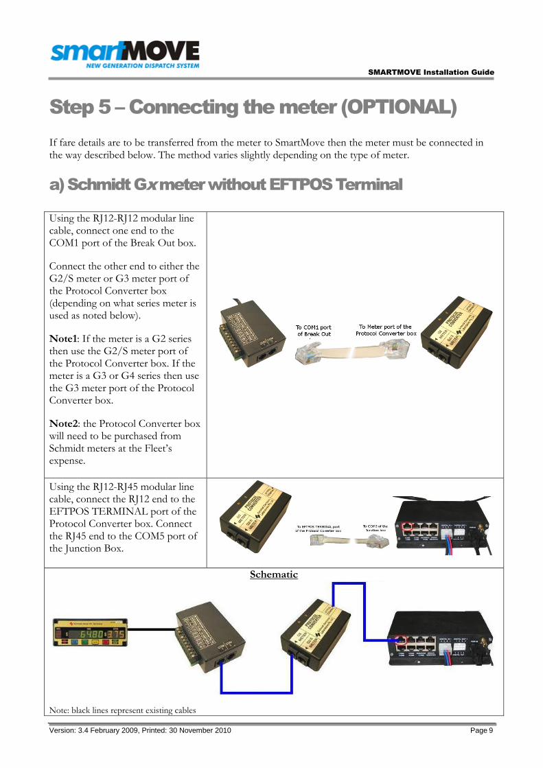
Step 5 – Connecting the meter (OPTIONAL)
If fare details are to be transferred from the meter to SmartMove then the meter must be connected in the way described below. The method varies slightly depending on the type of meter.
a) Schmidt Gx meter without EFTPOS Terminal
Using the RJ12-RJ12 modular line cable, connect one end to the COM1 port of the Break Out box.
Connect the other end to either the G2/S meter or G3 meter port of the Protocol Converter box (depending on what series meter is used as noted below).
Note1: If the meter is a G2 series then use the G2/S meter port of the Protocol Converter box. If the meter is a G3 or G4 series then use the G3 meter port of the Protocol Converter box.
Note2: the Protocol Converter box will need to be purchased from Schmidt meters at the Fleet’s expense.
Using the RJ12-RJ45 modular line cable, connect the RJ12 end to the EFTPOS TERMINAL port of the Protocol Converter box. Connect the RJ45 end to the COM5 port of the Junction Box.
Schematic
Note: black lines represent existing cables

SMARTMOVE Installation Guide
Version: 3.4 February 2009, Printed: 30 November 2010 Page 10
b) Schmidt Gx meter with EFTPOS Terminal
Using the RJ12-RJ12 modular line cable, connect one end to the COM1 port of the Break Out box.
Connect the other end to either the G2/S meter or G3 meter port of the Protocol Converter box (depending on what series meter is used as noted below).
Note1: If the meter is a G2 series then use the G2/S meter port of the Protocol Converter box. If the meter is a G3 or G4 series then use the G3 meter port of the Protocol Converter box.
Note2: the Protocol Converter box will need to be purchased from Schmidt meters at the Fleet’s expense.
With the RJ12-RJ12 modular line cable connecting the Protocol Converter box to the EFTPOS terminal, disconnect the Protocol Converter box end and connect it to the free RJ12 port of the Inline Coupler of the meter Listening cable.
Note1: Please advise SmartMove Support (ph: 0407 728 442) whether the meter is a Cabcharge meter or not.
With the short RJ12-RJ12 modular line cable connected to the other end of the Inline Coupler, connect it to the EFTPOS TERMINAL port of the Protocol Converter box.

SMARTMOVE Installation Guide
Version: 3.4 February 2009, Printed: 30 November 2010 Page 11
Connect the 9-pin serial cable to the COM4 port of the Junction box.
Schematic
Note: black lines represent existing cables
c) Martin Mkx meter without EFTPOS Terminal
If using the RJ12-RJ45 modular line cable, connect the RJ12 end to the COM1 port of the Break Out box. Connect the RJ45 end to the COM5 port of the Junction Box.
OR
If using the RJ12-RS232 cable, connect the RJ12 end to the COM1 port of the Break Out box. Connect the RS232 end to the COM4 port of the Junction Box.
Note1: Please advise SmartMove Support (ph: 0407 728 442) which Vehicle is using which type of cable.
OR

SMARTMOVE Installation Guide
Version: 3.4 February 2009, Printed: 30 November 2010 Page 12
Schematic
OR
Note: black lines represent existing cables
d) Martin Mkx meter with EFTPOS Terminal
With the RJ12-RJ12 modular line cable connecting the Break Out box to the EFTPOS terminal, disconnect the Break Out box end and connect it to the free RJ12 port of the Inline Coupler of the Meter Listening cable.
Note1: Please advise SmartMove Support (ph: 0407 728 442) whether the meter is a Cabcharge meter or not.
With the short RJ12-RJ12 modular line cable connected to the other end of the Inline Coupler, connect it to the COM1 port of the Break Out box.
Connect the 9-pin RS232 serial cable to the COM4 port of the Junction box.

SMARTMOVE Installation Guide
Version: 3.4 February 2009, Printed: 30 November 2010 Page 13
Schematic
Note: black lines represent existing cables
e) Novax Leda meter without EFTPOS Terminal
If using the RJ12-RJ45 modular line cable, connect the RJ12 end to one port of the Inline Coupler. Connect the RJ45 end to the COM5 port of the Junction Box. Connect the RJ12 cable from the meter to the other port of the Inline Coupler.
OR
If using the RJ12-RS232 cable, connect the RJ12 end to one port of the Inline Coupler. Connect the RS232 end to the COM4 port of the Junction Box. Connect the RJ12 cable from the meter to the other port of the Inline Coupler.
Note1: Please advise SmartMove Support (ph: 0407 728 442) which Vehicle is using which type of cable.
OR
SMARTMOVE Installation Guide
Version: 3.4 February 2009, Printed: 30 November 2010 Page 14
Schematic
OR
Note: black lines represent existing cables
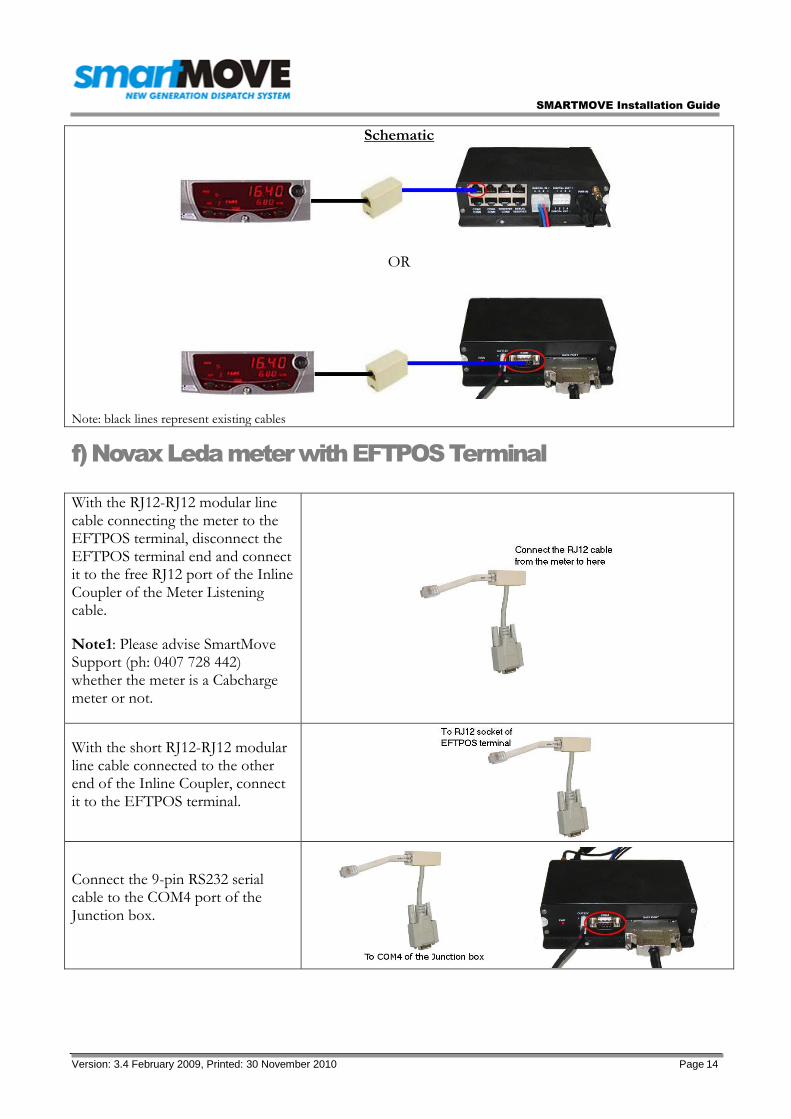
f) Novax Leda meter with EFTPOS Terminal
With the RJ12-RJ12 modular line cable connecting the meter to the EFTPOS terminal, disconnect the EFTPOS terminal end and connect it to the free RJ12 port of the Inline Coupler of the Meter Listening cable.
Note1: Please advise SmartMove Support (ph: 0407 728 442) whether the meter is a Cabcharge meter or not.
With the short RJ12-RJ12 modular line cable connected to the other end of the Inline Coupler, connect it to the EFTPOS terminal.
Connect the 9-pin RS232 serial cable to the COM4 port of the Junction box.

SMARTMOVE Installation Guide
Version: 3.4 February 2009, Printed: 30 November 2010 Page 15
Schematic
Note: black lines represent existing cables
Step 6 Fit GPRS (mobile phone) antenna
If supplied with a windscreen type antenna, stick the antenna to the top of the windscreen (driver's side) and run the cable down the A-Pillar.
If supplied with larger roof type antenna, mount it to the center of the roof and run the cable down the pillar to the junction box. This installation will achieve maximum gain. Alternatively, the antenna can be mounted to the roof rack.
If supplied with the smaller roof type antenna, mount it under the dome and run the cable down the pillar to the junction box.

SMARTMOVE Installation Guide
Version: 3.4 February 2009, Printed: 30 November 2010 Page 16
Step 7 Connect screen and power
Attach the 50-pin data cable and 12V power cable to the screen.
Fit the screen.
Connect the 12V battery lead to the junction box. The red wire should be attached to +12V and the black wire to -12V. A low amp fuse (eg 10 amp) should be wired in to the power cable to prevent damage to the junction box in case of any problems with the wiring. Fit a switch in a convenient position if there is a possibility the vehicle will be off the road for more than a day. Preferably wire separately from the radio to prevent possible interference.
Check power is supplied to junction box and screen (lights should be on). The startup screen will appear in around 30 seconds and the SmartMove login screen should appear in about a 2 minutes. You may need to switch the screen on using the centre button.
SMARTMOVE Installation Guide
Version: 3.4 February 2009, Printed: 30 November 2010 Page 17
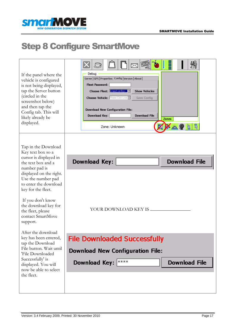
Step 8 Configure SmartMove
If the panel where the vehicle is configured is not being displayed, tap the Server button (circled in the screenshot below) and then tap the Config tab. This will likely already be displayed.
Tap in the Download Key text box so a cursor is displayed in the text box and a number pad is displayed on the right. Use the number pad to enter the download key for the fleet.
If you don't know the download key for the fleet, please contact SmartMove support.
After the download key has been entered, tap the Download File button. Wait until 'File Downloaded Successfully' is displayed. You will now be able to select the fleet.
YOUR DOWNLOAD KEY IS _________________
SMARTMOVE Installation Guide
Version: 3.4 February 2009, Printed: 30 November 2010 Page 18
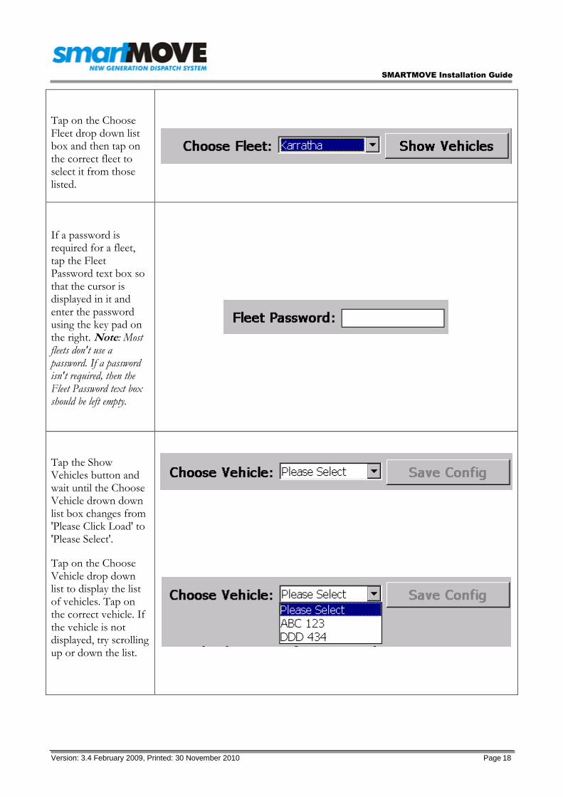
Tap on the Choose Fleet drop down list box and then tap on the correct fleet to select it from those listed.
If a password is required for a fleet, tap the Fleet Password text box so that the cursor is displayed in it and enter the password using the key pad on the right. Note: Most fleets don't use a password. If a password isn't required, then the Fleet Password text box should be left empty.
Tap the Show Vehicles button and wait until the Choose Vehicle drown down list box changes from 'Please Click Load' to 'Please Select'.
Tap on the Choose Vehicle drop down list to display the list of vehicles. Tap on the correct vehicle. If the vehicle is not displayed, try scrolling up or down the list.

SMARTMOVE Installation Guide
Version: 3.4 February 2009, Printed: 30 November 2010 Page 19
Tap the Save Config Button and wait for the Login panel to display. SmartMove is now configured for the vehicle.
Shortly afterwards the unit should show that it is connected to the server.
See V:\projects\CellTrack\web_orig_files_images\tims_files\SMVConfigVehicle.html and V:\projects\CellTrack\web_orig_files_images\tims_files\SMVServerTab.html

SMARTMOVE Installation Guide
Version: 3.4 February 2009, Printed: 30 November 2010 Page 20
Step 9 Test SmartMove
Look at the properties page on the Debugging screen and check that the car is configured for digital input. If the unit is configured for analogue call SmartMove support to have it changed.
With the meter switched on but not running, the car symbol at the bottom right should show one person in the car. With the meter running the symbol should show three people in the car
If the symbols are inverted the car needs to be reconfigured in the system – call SmartMove support and ask for the meter signal to be inverted.
If the symbol doesn’t change then check that the dome light goes on and off with the meter – a new bulb might be needed. If the light is working then check that the digital input line has been wired correctly.
NB: Not required for vehicles without meters
When the car is connected to the server, hold the panic button in for a second. The panic symbol should appear at the bottom right hand corner of the screen.
The panic must be cleared by smartMove support. Please call 0407 728 442.
Check that a GPS fix is obtained within 5 minutes. If no fix is obtained, move the car into the open , then check GPS connection or junction box and the 50pin data cable on the WaveOn screen.