smartraq r4 door operator - mceinc.com
TRANSCRIPT
Motion Control Engineering, Inc.11380 White Rock RoadRancho Cordova, CA 95742
voice 916 463 9200fax 916 463 9201www.mceinc.com
User Guide,SmarTRAQ Limitless Door Operator with Revision 4 Drive
Manual # 42-02-D004, Rev A1, May 2004
CopyrightCopyright 2004, Motion Control Engineering. All Rights Reserved.This document may not be reproduced, electronically or mechanically, in whole or in part, without written permission from Motion Control Engineering.
TrademarksAll trademarks or registered product names appearing in this document are the exclusive property of the respective owners.
Warning and DisclaimerAlthough every effort has been made to make this document as complete and accurate as possible, Motion Control Engineering and the document authors, publishers, distributors, and representatives have neither liability nor responsibility for any loss or damage arising from information contained in this document or from informational errors or omissions. Information contained in this document shall not be deemed to constitute a commitment to provide service, equipment, or software by Motion Control Engineering or the document authors, publishers, distributors, or representatives.
Limited WarrantyMotion Control Engineering (manufacturer) warrants its products for a period of 15 months from the date of shipment from its factory to be free from defects in workmanship and materials. Any defect appearing more than 15 months from the date of shipment from the factory shall be deemed to be due to ordinary wear and tear. Manufacturer, however, assumes no risk or liability for results of the use of the products purchased from it, including, but without limiting the generality of the forgoing: (1) The use in combination with any electrical or electronic components, circuits, systems, assemblies or any other material or equipment (2) Unsuitability of this product for use in any circuit, assembly or environment. Purchasers’ rights under this warranty shall consist solely of requiring the manufacturer to repair, or in manufacturer's sole discretion, replace free of charge, F.O.B. factory, any defective items received at said factory within the said 15 months and determined by manufacturer to be defective. The giving of or failure to give any advice or recommendation by manufacturer shall not constitute any warranty by or impose any liability upon the manufacturer. This warranty constitutes the sole and exclusive remedy of the purchaser and the exclusive liability of the manufacturer, AND IN LIEU OF ANY AND ALL OTHER WARRANTIES, EXPRESSED, IMPLIED, OR STATUTORY AS TO MERCHANTABILITY, FITNESS, FOR PURPOSE SOLD, DESCRIPTION, QUALITY PRODUCTIVENESS OR ANY OTHER MATTER. In no event will the manufacturer be liable for special or consequential damages or for delay in performance of this warranty.
Products that are not manufactured by MCE (such as drives, CRT's, modems, printers, etc.) are not covered under the above warranty terms. MCE, however, extends the same warranty terms that the original manufacturer of such equipment provide with their product (refer to the warranty terms for such products in their respective manual).

Important Precautions and Useful InformationThis preface contains information that will help you understand and safely maintain MCE equipment. We strongly recommend you review this preface and read this manual before installing, adjusting, or maintaining Motion Control Engineering equipment. This preface dis-cusses:
• Safety and Other Symbol Meanings
• Environmental Considerations
• In This Guide
Safety and Other Symbol Meanings
DangerThis manual symbol is used to alert you to procedures, instructions, or situations which, if not done properly, might result in personal injury or substantial equipment damage.
CautionThis manual symbol is used to alert you to procedures, instructions, or situations which, if not done properly, might result in equipment damage.
Note
This manual symbol is used to alert you to instructions or other immediately helpful information.
Environmental Considerations• Keep ambient temperature between 32 and 104 degrees F (0 to 40 degrees C).
• Prevent condensation on the equipment.
• Make certain that power line fluctuations are within plus or minus 5% of proper value.
In This Guide:This guide is the installation, adjustment, and troubleshooting guide for SmarTRAQ. When viewed online as a pdf file, hyperlinks link to related topics and informational websites. The manual includes:
• Contents: Table of Contents. When viewed online as a pdf file, hyperlinks in the Contents link to the associated topic in the body of the manual.
• SmarTRAQ: Product Description, installation, and troubleshooting instructions.
SmarTRAQ ContentsAbout SmarTRAQ . . . . . . . . . . . . . . . . . . . . . . . . . . . . . . . . . . . . . . . . . . . . . . . . . . . . .1
Product Description . . . . . . . . . . . . . . . . . . . . . . . . . . . . . . . . . . . . . . . . . . . . . . . . . 2Adaptability . . . . . . . . . . . . . . . . . . . . . . . . . . . . . . . . . . . . . . . . . . . . . . . . . . . . . . . . . . . . . . . . . 3
SmarTRAQ Models . . . . . . . . . . . . . . . . . . . . . . . . . . . . . . . . . . . . . . . . . . . . . . . . . . . . . . . . . 4
Installation Checklist . . . . . . . . . . . . . . . . . . . . . . . . . . . . . . . . . . . . . . . . . . . . . . . . . 5
Installation . . . . . . . . . . . . . . . . . . . . . . . . . . . . . . . . . . . . . . . . . . . . . . . . . . . . . . . . . 6Connector J6 Wiring and Verification . . . . . . . . . . . . . . . . . . . . . . . . . . . . . . . . . . . . . . . . . . . . 8
SmarTRAQ Adjustments . . . . . . . . . . . . . . . . . . . . . . . . . . . . . . . . . . . . . . . . . . . . . . 9Checking Motor Rotation . . . . . . . . . . . . . . . . . . . . . . . . . . . . . . . . . . . . . . . . . . . . . . . . . . . . . . 9SmarTRAQ Programmer Controls . . . . . . . . . . . . . . . . . . . . . . . . . . . . . . . . . . . . . . . . . . . . . . 10Learning Full Open and Full Close Positions . . . . . . . . . . . . . . . . . . . . . . . . . . . . . . . . . . . . . 11
Running the Learn Operation . . . . . . . . . . . . . . . . . . . . . . . . . . . . . . . . . . . . . . . . . . . . . . . 11Verify Door Operation . . . . . . . . . . . . . . . . . . . . . . . . . . . . . . . . . . . . . . . . . . . . . . . . . . . . . . . . 12Adjusting Parameters . . . . . . . . . . . . . . . . . . . . . . . . . . . . . . . . . . . . . . . . . . . . . . . . . . . . . . . . 13
Parameter Adjustment Example . . . . . . . . . . . . . . . . . . . . . . . . . . . . . . . . . . . . . . . . . . . . . 15Measuring Door Closing Force. . . . . . . . . . . . . . . . . . . . . . . . . . . . . . . . . . . . . . . . . . . . . . . 15Door Closing Time Compliance . . . . . . . . . . . . . . . . . . . . . . . . . . . . . . . . . . . . . . . . . . . . . . 16
Troubleshooting . . . . . . . . . . . . . . . . . . . . . . . . . . . . . . . . . . . . . . . . . . . . . . . . . . . . 21Helpful Hints . . . . . . . . . . . . . . . . . . . . . . . . . . . . . . . . . . . . . . . . . . . . . . . . . . . . . . . . . . . . . . . 21
Door Open and Door Close Logic. . . . . . . . . . . . . . . . . . . . . . . . . . . . . . . . . . . . . . . . . . . . . 21Self-Holding . . . . . . . . . . . . . . . . . . . . . . . . . . . . . . . . . . . . . . . . . . . . . . . . . . . . . . . . . . . . . . 21Door Close Limit and Door Open Limit . . . . . . . . . . . . . . . . . . . . . . . . . . . . . . . . . . . . . . . 21Limit #1 and Limit #2 . . . . . . . . . . . . . . . . . . . . . . . . . . . . . . . . . . . . . . . . . . . . . . . . . . . . . 22Car Door Bumpers . . . . . . . . . . . . . . . . . . . . . . . . . . . . . . . . . . . . . . . . . . . . . . . . . . . . . . . . 22Belt and Chain Tension . . . . . . . . . . . . . . . . . . . . . . . . . . . . . . . . . . . . . . . . . . . . . . . . . . . . 22Motor Terminal Designation . . . . . . . . . . . . . . . . . . . . . . . . . . . . . . . . . . . . . . . . . . . . . . . . 23Learn Operation. . . . . . . . . . . . . . . . . . . . . . . . . . . . . . . . . . . . . . . . . . . . . . . . . . . . . . . . . . . 23Changing Parameters . . . . . . . . . . . . . . . . . . . . . . . . . . . . . . . . . . . . . . . . . . . . . . . . . . . . . . 23Stall Protection. . . . . . . . . . . . . . . . . . . . . . . . . . . . . . . . . . . . . . . . . . . . . . . . . . . . . . . . . . . . 23Door Open and Door Close Protection Timers. . . . . . . . . . . . . . . . . . . . . . . . . . . . . . . . . . 23Temporary Operation for Evaluation . . . . . . . . . . . . . . . . . . . . . . . . . . . . . . . . . . . . . . . . . 23Encoder Cable . . . . . . . . . . . . . . . . . . . . . . . . . . . . . . . . . . . . . . . . . . . . . . . . . . . . . . . . . . . 24Auto Reset. . . . . . . . . . . . . . . . . . . . . . . . . . . . . . . . . . . . . . . . . . . . . . . . . . . . . . . . . . . . . . . 24Control Signal Priority . . . . . . . . . . . . . . . . . . . . . . . . . . . . . . . . . . . . . . . . . . . . . . . . . . . . 24Control Signal Status. . . . . . . . . . . . . . . . . . . . . . . . . . . . . . . . . . . . . . . . . . . . . . . . . . . . . . 24
Functional Troubleshooting . . . . . . . . . . . . . . . . . . . . . . . . . . . . . . . . . . . . . . . . . . . . . . . . . . . 25Power Up . . . . . . . . . . . . . . . . . . . . . . . . . . . . . . . . . . . . . . . . . . . . . . . . . . . . . . . . . . . . . . . . 25Motor Synchronization . . . . . . . . . . . . . . . . . . . . . . . . . . . . . . . . . . . . . . . . . . . . . . . . . . . . 26First Door Closing . . . . . . . . . . . . . . . . . . . . . . . . . . . . . . . . . . . . . . . . . . . . . . . . . . . . . . . . 26Learn Process . . . . . . . . . . . . . . . . . . . . . . . . . . . . . . . . . . . . . . . . . . . . . . . . . . . . . . . . . . . . . 27First Open/Close After Cycling Power. . . . . . . . . . . . . . . . . . . . . . . . . . . . . . . . . . . . . . . . 29Opening and Closing . . . . . . . . . . . . . . . . . . . . . . . . . . . . . . . . . . . . . . . . . . . . . . . . . . . . . . 30Reopening and Reclosing . . . . . . . . . . . . . . . . . . . . . . . . . . . . . . . . . . . . . . . . . . . . . . . . . . . 31Torque Adjustment . . . . . . . . . . . . . . . . . . . . . . . . . . . . . . . . . . . . . . . . . . . . . . . . . . . . . . . . 32
Firmware Upgrades . . . . . . . . . . . . . . . . . . . . . . . . . . . . . . . . . . . . . . . . . . . . . . . . . 33Replacing Microchips . . . . . . . . . . . . . . . . . . . . . . . . . . . . . . . . . . . . . . . . . . . . . . . . . . . . . . . . 34
Unit Replacement . . . . . . . . . . . . . . . . . . . . . . . . . . . . . . . . . . . . . . . . . . . . . . . . . . 35

List of FiguresFigure 1.1 Motor Configurations . . . . . . . . . . . . . . . . . . . . . . . . . . . . . . . . . . . . . . . . . . . 4Figure 1.2 SmarTRAQ Wiring Diagram . . . . . . . . . . . . . . . . . . . . . . . . . . . . . . . . . . . . . .7Figure 1.3 Verifying Contact States at J6 Door Control Inputs . . . . . . . . . . . . . . . . . . 8Figure 1.4 Inverter Drive Programmer Switches . . . . . . . . . . . . . . . . . . . . . . . . . . . . . .10Figure 1.5 Motion Profile . . . . . . . . . . . . . . . . . . . . . . . . . . . . . . . . . . . . . . . . . . . . . . . . .14Figure 1.6 One-inch Conduit Simplifies Connection . . . . . . . . . . . . . . . . . . . . . . . . . 35
List of TablesTable 1.1 SmarTRAQ Specifications, Interface Data, and Code Compliance . . . . . . . .2Table 1.2 Motor Connections from Wiring Diagram . . . . . . . . . . . . . . . . . . . . . . . . . . 9Table 1.3 Motor Connections if Rotation is Counter-Clockwise as Doors Close . . . . 9Table 1.4 Inverter Drive Parameters . . . . . . . . . . . . . . . . . . . . . . . . . . . . . . . . . . . . . . . .13Table 1.5 Center Parting Doors . . . . . . . . . . . . . . . . . . . . . . . . . . . . . . . . . . . . . . . . . . . . 17Table 1.6 Center Parting Doors without Reopening Device (Nudging) . . . . . . . . . . .18Table 1.7 Side Slide Doors . . . . . . . . . . . . . . . . . . . . . . . . . . . . . . . . . . . . . . . . . . . . . . . .19Table 1.8 Side Slide Doors without Re-Opening (Nudging) Device . . . . . . . . . . . . . 20


• About SmarTRAQ• Product Description• Installation• Adjustment• Troubleshooting
SmarTRAQ
About SmarTRAQ SmarTRAQ is a closed-loop technology, limitless door operator designed to replace older mechanical circuits, cams, and resistors with a digital control sys-tem providing precise door operation and reliable performance. Because Smar-TRAQ is limitless, Door Open Limit and Door Closed Limit signals are generated
electronically — DOL and DCL mechanical switches are not required. SmarTRAQ dramatically improves door operation regardless of lobby door mass and wind loading. SmarTRAQ is A17.1, CSA-B44.1 compliant.
SmarTRAQ provides flexibility:
• Choose to modernize an existing installation economically with a new brushless motor and microprocessor-based inverter drive (re-using existing mechanical equipment)
• Replace the complete operator with a new brushless motor, microprocessor-based inverter drive, and new center-parting or side-slide door operator package.
This user guide provides installation, adjustment, and troubleshooting information for the SmarTRAQ motor and inverter drive. If your installation includes a new door operator package, additional instructions will be provided.
1

SmarTRAQ
Product DescriptionThe SmarTRAQ limitless, closed-loop, door operator includes a permanent-magnet, brushless motor with a built-in encoder and a microprocessor-based inverter drive. The compact inverter drive enclosure mounts easily on the elevator car. The motor replaces the original motor when re-using existing operator packages or mounts to the new operator package when the complete door operator is being replaced or newly installed.
Table 1.1 SmarTRAQ Specifications, Interface Data, and Code Compliance
Door Operator Drive Technical Data
Input Voltage 120/208/240VAC, 50/60Hz, Single-phase
Output Voltage 3-Phase, 30VAC, 9A (26A peak)
Power Requirement 300VA
Controller Type Closed Loop, Distance and Velocity Feedback, Limitless
Door Motor Technical Data
Type Three-phase, synchronous, brushless motor with perma-nent magnet excitation and built-in digital encoder
Motor 0.564 HP, 3-Phase AC, 8-Pole, 30 Volt, 9A (26A peak), 0 — 2000 RPM, 0 — 133Hz
Encoder 640 PPR (Pulses Per Revolution)
Elevator Control Interface Data
Input Signals Door Open Door CloseNudgingHeavy Door
Input Signal Level Dry Contact
Output Signals Door Open LimitDoor Close LimitLimit 1Limit 2
Output Signal Level N.O./N.C. Contact, 10 Amp
Code Compliance
For ASME A17.1-1996 (Rule 210.15), ASME A17.1-2000/CSA B44-00 (Requirement 2.26.5), or CSA B44-94 (Requirement 3.12.1.5) compliance, mechanical Door Position Monitoring Switch must be provided.
2 Manual # 42-02-D004 Rev. A1

Product Description
AdaptabilitySmarTRAQ offers wide mechanical and electrical interface, providing a cost-effective solution for modernization of existing door operators or for new installations. SmarTRAQ models sup-port:
• MCE
• Center-Parting Door Operator Package
• Two-Speed Center-Parting Door Operator Package
• Single-Speed Side Slide Door Operator Package
• Two-Speed Side Slide Door Operator Package
• Westinghouse
• Model A Series
• Model B Series
• Model BB2
• Model E Series
• Model EZ
• Model HY
• Model MG
• Haughton
• T
• T1
• TH
• Montgomery
• MAC Series
• Dover
• DC Series
• HD Series
• Otis
• 6970
• 7300
• 7782
• GAL
• All Models
• Armor
• C4
3
SmarTRAQ
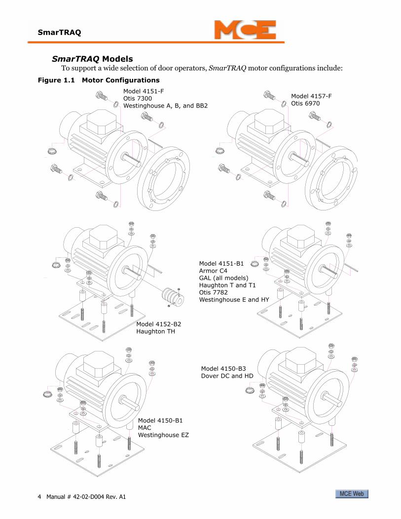
SmarTRAQ ModelsTo support a wide selection of door operators, SmarTRAQ motor configurations include:
Figure 1.1 Motor Configurations
Model 4151-FOtis 7300Westinghouse A, B, and BB2
Model 4157-FOtis 6970
Model 4152-B2Haughton TH
Model 4151-B1Armor C4GAL (all models)Haughton T and T1Otis 7782Westinghouse E and HY
Model 4150-B1MACWestinghouse EZ
Model 4150-B3Dover DC and HD
4 Manual # 42-02-D004 Rev. A1

Installation Checklist
Installation ChecklistBefore beginning installation, make sure you have what you need:
1. A fused 120, 208, or 240VAC, single-phase, 350VA minimum supply available from the elevator Controller to the door operator drive. Input voltage must be within +/- 5% of specified voltage. (MCE does not recommend using the car lighting circuit for door power.)
2. A sufficient number of wires from the Controller to the door operator drive:
• Two wires for power
• Three wires for drive common (different from Controller common), door open, and door close. One additional wire if nudging is required. An additional wire if heavy door is required. (Three to five wires.)
• Three wires for Controller common (different from Drive common), DCL, and DOL. If DCL and DOL do not share a common wire, then four wires are required. (Three to four wires.)
• Three or four wires for auxiliary Limit #1 and Limit #2 for retiring cam, limited door reversal, advance start, etc. are required (depending upon how these limits are wired on your job).
Note
If compliance to ASME A17.1-1996 (Rule 1210.15), ASME A17.1-2000/CSA B44-00 (require-ment 2.28.5) or CSA B44-94 (requirement 3.12.1.5) is required, a mechanical Door Position Monitoring Switch must be provided.
3. Dry (unused), normally open contacts for door open and door close and/or nudging and heavy door (position contact). (If not, can the required contacts be made available by reusing existing contacts for the original door operator or will relays need to be installed in the Controller or on the car?)
4. If installing an Upgrade Kit, all belts, cables, hanger rollers, gibs, clutches, linkages, bearings, and related door operator equipment must be in good condition.
5. If installing a complete door operator, any door operator equipment being retained must be in good condition.
6. All door operators require door open and door close bumpers. Bumpers must be in good condition for proper operation. MCE supplies bumpers for GAL and MAC Door Opera-tors with the Upgrade Kits. Most other operators already have open and close bumpers.
7. Thoroughly read this User Guide before starting installation, especially the SmarTRAQ Adjustments and Troubleshooting sections.
8. If, for any reason, the MCE drive needs to be replaced, it MUST be replaced as one com-plete unit or the WARRANTY WILL BE VOID. The defective drive must be returned to MCE.
5

SmarTRAQ
Installation1. Remove existing motor (upgrade kit installations only). SmarTRAQ inverter drive may
be used only with SmarTRAQ motor.2. If the car door gate switch is part of the existing limit switch box, leave it in place. Other-
wise, limit switches are not required.
3. Install new motor.
Note
All door operators must have FULL OPEN and FULL CLOSE bumpers.
CautionOtis 6970 Door Operators: When removing the Otis motor, access to the lower bolt is through the inspection cover on the front of the gear case:
• Remove the inspection cover.• Rotate the gear so one of the large holes exposes the lower bolt.• Be careful not to drop the bolt or the lock washer in the gear case.• Oil checks need to be adjusted for minimal effect. However, do not completely back out
existing oil check adjustments.
4. Unless the existing belt is in like-new condition, replace it with a robust, grip-type belt with notches.
5. Adjust belt tension. (Closed-loop control requires minimal belt elasticity, slack, or slip-page.)
6. Adjust all chains and cables for minimal slack.7. Mount the inverter drive enclosure in a location that allows the provided 8-foot (2.5
meter) encoder cable to easily reach from the motor to the enclosure. (Coil any excess cable length inside the drive enclosure. Avoid trimming the encoder cable.)
Note
If the encoder cable is trimmed, a brown (unused) wire will be exposed. Do not use the brown wire. Note that the original yellow/green wire was actually a short piece soldered to the cable shield. This piece must be replaced, soldered to the shield, and connected as shown in the wir-ing diagram provided.
8. Check that the inverter drive On/Off switch is in the OFF position. Connect the encoder cable and power wires from the motor to the inverter drive as shown in the wiring dia-gram. Please refer to “SmarTRAQ Wiring Diagram” on page 7.
9. Complete wiring connections between the inverter drive enclosure and the elevator con-troller as shown in the wiring diagram. The drive is shipped configured for 120VAC power. If you are using 208 or 240VAC, connect the 2A wire from the inverter drive fuse block to the voltage-select terminal as indicated in the wiring diagram. Please refer to “SmarTRAQ Wiring Diagram” on page 7 and additional information on page 8. Refer to the controller manufacturer job prints for controller-related wiring.
6 Manual # 42-02-D004 Rev. A1
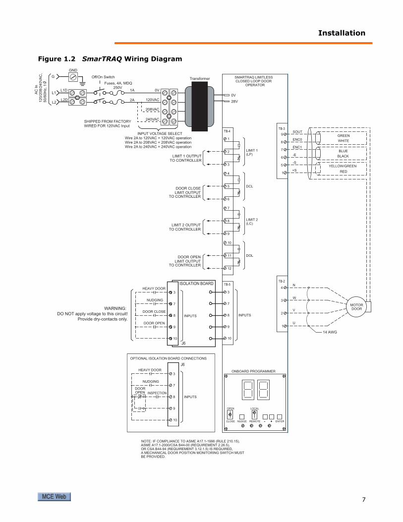
Installation
Figure 1.2 SmarTRAQ Wiring Diagram
9
10
7
8
CLOSED LOOP DOORSMARTRAQ LIMITLESS
INPUTS
TB-5
1
2
3
4
TB-2
1
TB-3
5
6
9
7
8
+S
-S
-E
ENC1
ENC0
SOUT
MOTOR
V
U
W
N
DOOR
14 AWG
OPERATOR
-- ++ ENTER
3
NUDGE REMOTE
LOCALOPEN
CLOSE
ONBOARD PROGRAMMER
12
11 DOL
6
5
LIMIT 2
TB-4
YELLOW/GREEN
RED
BLUE
BLACK
WHITE
GREEN
10
4
DOOR OPENLIMIT OUTPUT
TO CONTROLLER
TO CONTROLLERLIMIT 2 OUTPUT
9
7
8
LIMIT 1 OUTPUTTO CONTROLLER
3
2
1
LIMIT 1
NOTE: IF COMPLIANCE TO ASME A17.1-1996 (RULE 210.15),ASME A17.1-2000/CSA B44-00 (REQUIREMENT 2.26.5),OR CSA B44-94 (REQUIREMENT 3.12.1.5) IS REQUIRED,A MECHANICAL DOOR POSITION MONITORING SWITCH MUSTBE PROVIDED.
(LP)
(LC)
TO CONTROLLERLIMIT OUTPUTDOOR CLOSE
DCL
Off/On Switch
GND
Fuses, 4A, MDQ250V
1A
2A
0V
120VAC
208VAC
240VAC
0V
28V
Transformer
L1D
L2D
L1
L2
G
A
C In
120/2
08/2
40V
AC
,50/6
0H
z, 1
SHIPPED FROM FACTORYWIRED FOR 120VAC Input
INPUT VOLTAGE SELECTWire 2A to 120VAC = 120VAC operationWire 2A to 208VAC = 208VAC operationWire 2A to 240VAC = 240VAC operation
OPEN
HEAVY DOOR
10
9
NUDGING
3
8
7
INPUTS
INPUTS
OPTIONAL ISOLATION BOARD CONNECTIONS
DOOR
INSPECTION
ISOLATION BOARD
9
10
7
8
3
DOOR OPEN
DOOR CLOSE
NUDGING
HEAVY DOOR
WARNING:
DO NOT apply voltage to this circuit!
Provide dry-contacts only.
J6
J6
7
SmarTRAQ
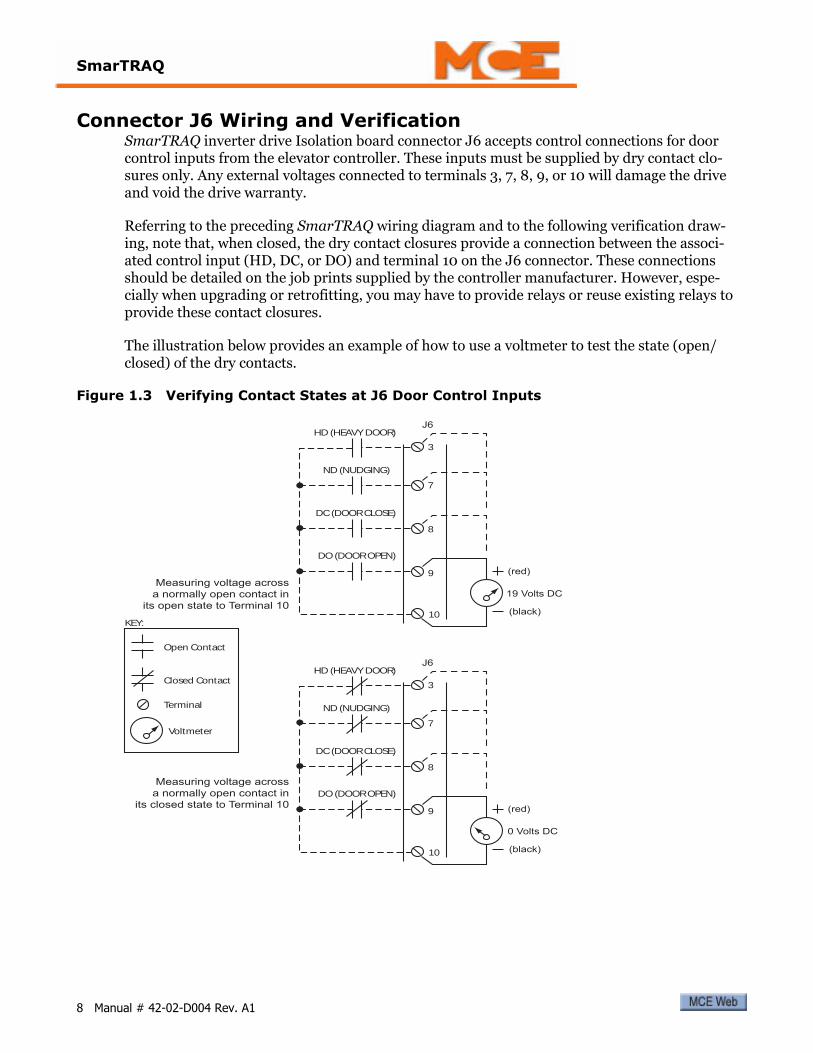
Connector J6 Wiring and VerificationSmarTRAQ inverter drive Isolation board connector J6 accepts control connections for door control inputs from the elevator controller. These inputs must be supplied by dry contact clo-sures only. Any external voltages connected to terminals 3, 7, 8, 9, or 10 will damage the drive and void the drive warranty.
Referring to the preceding SmarTRAQ wiring diagram and to the following verification draw-ing, note that, when closed, the dry contact closures provide a connection between the associ-ated control input (HD, DC, or DO) and terminal 10 on the J6 connector. These connections should be detailed on the job prints supplied by the controller manufacturer. However, espe-cially when upgrading or retrofitting, you may have to provide relays or reuse existing relays to provide these contact closures.
The illustration below provides an example of how to use a voltmeter to test the state (open/closed) of the dry contacts.
Figure 1.3 Verifying Contact States at J6 Door Control Inputs
Open Contact
Voltmeter
Closed Contact
Terminal
KEY:
7
3
8
9
10
ND (NUDGING)
DC (DOOR CLOSE)
HD (HEAVY DOOR)
DO (DOOR OPEN)
J6
19 Volts DC
(black)
(red)
0 Volts DC
(black)
(red)
Measuring voltage acrossa normally open contact in
its closed state to Terminal 10
Measuring voltage acrossa normally open contact in
its open state to Terminal 10
7
3
8
9
10
ND (NUDGING)
DC (DOOR CLOSE)
HD (HEAVY DOOR)
DO (DOOR OPEN)
J6
8 Manual # 42-02-D004 Rev. A1

SmarTRAQ Adjustments
SmarTRAQ AdjustmentsThis section describes:
• Checking motor rotation• SmarTRAQ Programmer Controls
• Learning Full Open and Full Close positions• Verifying Operation• Adjusting parameters
Checking Motor RotationMotor control connections from inverter drive enclosure terminals TB2 and TB3 to the motor assume clockwise motor rotation when elevator doors are closing. It is important to verify that this is the case:
1. Manually open and close elevator doors while watching motor rotation.2. Viewed from the motor shaft end, motor must rotate clockwise when doors are closing.
If so, connections shown in the wiring diagram and in the table below are correct:
3. If, as viewed from the shaft end, motor rotates counter-clockwise when doors are clos-ing, connections must be changed as shown in the following table:
Table 1.2 Motor Connections from Wiring Diagram
Motor TB2 Connector
U1 Terminal 1V1 Terminal 2W1 Terminal 3N Terminal 4
TB3 Connector
SOUT Terminal 9ENC0 (white) Terminal 8ENC1 (blue) Terminal 7-E Terminal 6-S Terminal 5+S Terminal 1
Table 1.3 Motor Connections if Rotation is Counter-Clockwise as Doors Close
Motor TB2 Connector
U1 Terminal 1V1 Terminal 3 (changed)W1 Terminal 2 (changed)N Terminal 4
TB3 Connector
SOUT Terminal 9ENC0 (white) Terminal 7 (changed)ENC1 (blue) Terminal 8 (changed)-E Terminal 6-S Terminal 5+S Terminal 1
9
SmarTRAQ
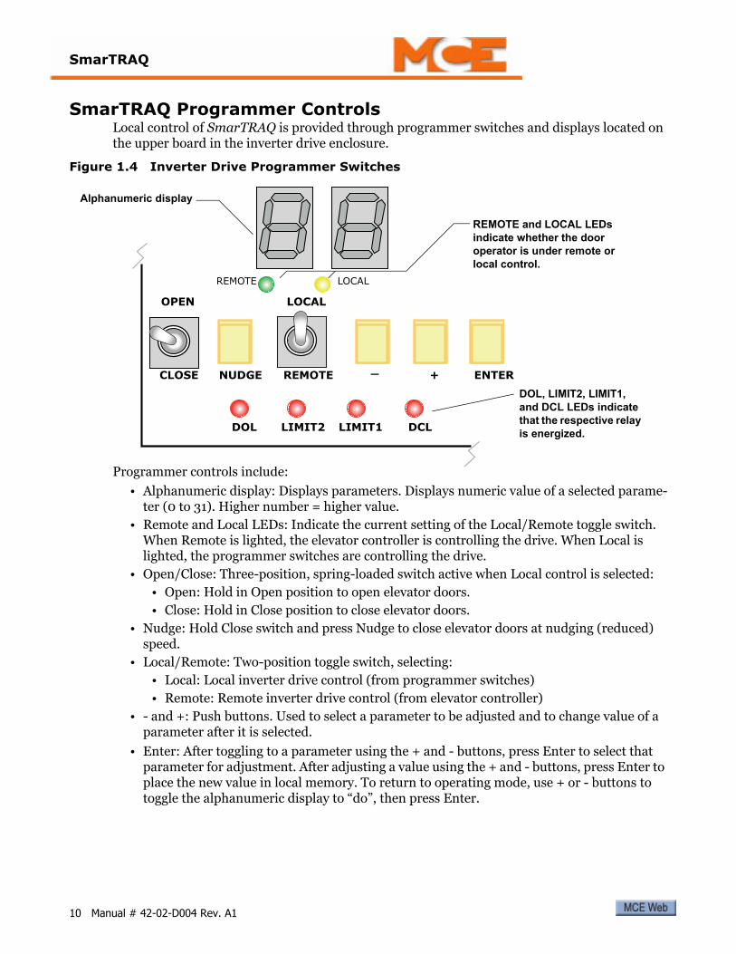
SmarTRAQ Programmer ControlsLocal control of SmarTRAQ is provided through programmer switches and displays located on the upper board in the inverter drive enclosure.
Figure 1.4 Inverter Drive Programmer Switches
Programmer controls include:
• Alphanumeric display: Displays parameters. Displays numeric value of a selected parame-ter (0 to 31). Higher number = higher value.
• Remote and Local LEDs: Indicate the current setting of the Local/Remote toggle switch. When Remote is lighted, the elevator controller is controlling the drive. When Local is lighted, the programmer switches are controlling the drive.
• Open/Close: Three-position, spring-loaded switch active when Local control is selected:• Open: Hold in Open position to open elevator doors.• Close: Hold in Close position to close elevator doors.
• Nudge: Hold Close switch and press Nudge to close elevator doors at nudging (reduced) speed.
• Local/Remote: Two-position toggle switch, selecting:• Local: Local inverter drive control (from programmer switches)• Remote: Remote inverter drive control (from elevator controller)
• - and +: Push buttons. Used to select a parameter to be adjusted and to change value of a parameter after it is selected.
• Enter: After toggling to a parameter using the + and - buttons, press Enter to select that parameter for adjustment. After adjusting a value using the + and - buttons, press Enter to place the new value in local memory. To return to operating mode, use + or - buttons to toggle the alphanumeric display to “do”, then press Enter.
CLOSE NUDGE REMOTE _ + ENTER
OPEN LOCAL
LOCALREMOTE
LIMIT1LIMIT2DOL DCL
DOL, LIMIT2, LIMIT1, and DCL LEDs indicate that the respective relay is energized.
REMOTE and LOCAL LEDs indicate whether the door operator is under remote or local control.
Alphanumeric display
10 Manual # 42-02-D004 Rev. A1

SmarTRAQ Adjustments
Learning Full Open and Full Close PositionsDoor Open and Door Close Limits are learned during an automated learn process as current rises when doors reach full open or full close. Once limits are learned, SmarTRAQ is able to dis-tinguish between an obstruction and full open or full close positions. DOL (Door Open Limit) and DCL (Door Close Limit) are learned only within the last 1/2” of door travel in either direc-tion.
• Doors Full Open: Door Open Limit is energized and DOL LED lights• Doors Full Closed: Door Close Limit is energized and DCL LED lights
Running the Learn Operation1. Verify that elevator doors are closed.2. Place Local/Remote switch in the Local position.
3. Turn on power.
For a few seconds, dashes will be displayed on the LED display. Then, the dash on the right hand display will disappear. The inverter drive is ready to accept input.
4. Hold the Open/Close switch in the Close position until PL is displayed and the DCL LED lights. (Motor will cog to synchronize rotor.)
5. Press Enter to select the PL parameter.
6. Press Enter a second time.
7. Press - (minus) to display Lr (Learn).
8. Press Enter.
Dashes will be displayed for a moment, then PL will appear. Doors will automatically open at low speed to FULL OPEN position and will then automatically close at low speed to FULL CLOSE position. Learning is complete.
11
SmarTRAQ
Verify Door Operation
Note
Whenever power is turned on (cycled), the first open operation will be at Low Speed.
To verify door operation:
1. Hold Open/Close in Open position. Doors will open and detect Full Open position. DOL should be displayed.
2. Hold Open/Close in Close position. Doors will close and detect Full Close position. DCL should be displayed.
Door Operation Example When in Local mode, you can operate the doors using the programmer switches. To open the doors:
1. Hold the Open/Close switch to Open. Pause at any point if desired. The Limit 2 LED will light at some (user adjustable, LC parameter) point as the doors are opening. When the Door Open Limit is reached (DOL relay energized), the DOL LED will light.
To close the doors:
1. Hold the Open/Close switch to Close. Pause at any point if desired. The Limit 1 LED will light at some (user adjustable, LP parameter) point as the doors are closing. When the Door Close Limit is reached (DCL relay energized), the DCL LED will light.
To close at nudging speed:
1. Hold the Open/Close switch to Close. Press the Nudge button. The doors will close at reduced speed.
12 Manual # 42-02-D004 Rev. A1

SmarTRAQ Adjustments
Adjusting ParametersAll door operator adjustments are made by selecting and changing parameters using inverter drive programmer switches. All parameter values are numeric, from 0 to 31. The higher the number, the greater the parameter value.
Note
Parameter values can only be changed or viewed when elevator doors are Full Closed and Door Close Limit LED is lighted.
After changing parameters, you must select the parameter “do” and press Enter to put door operator back in operating mode. You must also place the Local/Remote switch back in Remote position. (Otherwise, operator will not respond to open or close commands from elevator con-troller.)
Use the following table and the Motion Profile illustration to adjust parameters.
Table 1.4 Inverter Drive Parameters
Parameter Description
PL Start Open Position: Position where doors start to accelerate. Higher value = Position farther from full close.
P2 Open Slowdown Position: Position where doors begin to reduce high opening speed and decelerate to low opening speed. Higher value = High speed reduces nearer to full open position.
P7 Close Slowdown Position: Position where doors begin to reduce high closing speed and decelerate to low closing speed. Higher value = High speed reduces nearer to full close position.
Po Reopen Slowdown Position: Higher value = Reopen slowdown position starts nearer to full open.
Pc Reclose Slowdown Position: Higher value = Reclose slowdown position starts nearer full close.
Pr Reopen Distance: Distance from full open where Po parameter, Reopen Slowdown Position, and Ar parameter, Reopen Deceleration, can be activated. 00 value = from full open to 75% of full open. Setting parameter from 01 to 31 = from 75% of full open to 25% of full open. Note: Most door operators will not require adjustment of this parameter. This parameter is factory set to 00. Should be set to 00 unless abso-lutely necessary. See Caution following this table.
U0 Start Open Speed: Higher value = More speed.U1 High Opening Speed: Higher value = More speed.U2 Low Opening Speed: Higher value = More speed.U3 High Closing Speed: Higher value = More speed.U4 Low Closing Speed: Higher value = More speed.Ud Nudging Speed: Higher value = More speed.A0 Opening Acceleration: Higher value = Faster acceleration.A1 Opening Deceleration: Higher value = Faster deceleration.A2 Closing Acceleration: Higher value = Faster acceleration.A3 Closing Deceleration: Higher value = Faster deceleration.Ab Braking Deceleration: Deceleration during door reversal. Higher value = More decel-
eration.Ar Reopen Deceleration: Higher value = Faster deceleration.F3 Heavy Door High Closing Speed: Higher value = More speed. This value must be
lower than U3.F7 Heavy Door Close Slowdown Position: Position where doors begin to reduce high
closing speed and decelerate to low closing speed. Higher value = High speed reduces nearer to full close position.
13

SmarTRAQ
Note
Torque adjustment is accomplished by adjusting parameters C1, C2, Co, Cc, and Cb. Anytime these adjustments are changed, the Learn process must be repeated.
CautionPr and Cb parameters should always be set to “00” unless absolutely necessary. Please refer to “Opening and Closing” on page 30 for Cb. Please refer to “Reopening and Reclosing” on page 31 for Pr.
Figure 1.5 Motion Profile
Fd Heavy Door Nudging Speed: Higher values = More Speed.C1 Full Open Torque: Higher value = Higher Full Open Torque.C3 Close Torque: Higher value = More torque.Co Hold Open Torque: Higher value = More torque. Torque when doors are full open.Cc Hold Close Torque: Higher value = More torque. Torque when doors are full close. Cb Braking torque: Limits braking torque during slowdown. Higher Value = More braking
torque. Lower Value = Less braking torque. 00 value has no effect. Should be set to 00 unless absolutely necessary. See Caution following this table.
LP Limit 1: Higher value = Output turns on when doors are nearer to close position. Lower value = Output turns on when doors are farther from full close position.
LC Limit 2: Higher value = Output turns on when doors are nearer to open position. Lower value = Output turns on when doors are farther from full open position.
do Select Operation Mode: Once a parameter is adjusted, operation mode must be selected. Otherwise, door operator will not respond to open or close commands.
Lr Learn Command:
Table 1.4 Inverter Drive Parameters
Parameter Description
LP
LC
14 Manual # 42-02-D004 Rev. A1

SmarTRAQ Adjustments
Parameter Adjustment ExampleTo adjust a parameter (U1, high opening speed, in this example):
1. Check that the elevator doors are fully closed.
Note
Parameter values can only be changed or viewed when elevator doors are Full Closed and Door Close Limit LED is lighted.
2. Place the Local/Remote switch in the Local position.
3. Hold the Open/Close switch to Close until the alphanumeric display shows “PL” and DCL LED is lighted.
4. Use the + and/or - buttons to toggle to the desired parameter (U1 in this example).
5. Press Enter. The current value of the parameter will be displayed (0 - 31).
6. Use the + and/or - buttons to change the value.
7. When the desired value is displayed, press Enter to hold it in local memory.
8. If desired, continue setting additional parameters.
9. When ready to return to operating mode, use the + and - buttons to change the display to “do”, then press Enter.
10. Place the Local/Remote switch back to the Remote position.
Note
After adjusting a parameter, always re-learn Open/Close limits. Please refer to “Learning Full Open and Full Close Positions” on page 11.
Measuring Door Closing ForceTo measure door closing force:
1. Park the car at a floor.2. Begin to close the doors. Allow them to close 1/3 to 2/3 of their normal travel, then stop
them.
3. Insert a force measuring device appropriate to measure 30 lbf against the stopped door. Slowly release the doors so that they are now held stationary by the measuring device.
4. Slowly back off on the device until the door just starts to move. At this point, the door and measuring forces are approximately equal and the closing force value may be read.
15

SmarTRAQ
Door Closing Time ComplianceIf you are installing a job in a jurisdiction requiring compliance to Requirement 2.13.4.2.4 of ASME A17.1-2000 you must apply one of the Door Data Plate labels included with this manual to the door operator or crosshead. The data tags must be properly completed to show:
• Month and year of installation
• Typical floor door mass
• Minimum code closing time (resulting in average kinetic energy of less than 7.37 foot pounds) at normal closing speed with typical floor door mass
• Minimum code closing time (resulting in average kinetic energy of less than 2.50 foot pounds) at reduced/nudging closing speed with typical floor door mass
• Heavy door mass (where applicable) and landings affected
• Minimum code closing time (resulting in average kinetic energy of less than 7.37 foot pounds) at normal closing speed with heavy door mass
• Minimum code closing time (resulting in average kinetic energy of less than 2.50 foot pounds) at reduced/nudging closing speed with heavy door mass
The “Minimum Closing Time” tables on the following pages reflect an average kinetic energy of 7.37 foot pounds (2.50 foot pounds, nudging) and provide the minimum code closing times for most normal door configurations and sizes (normal and nudging operation).
When using the tables, consider:
• Closing Time/Distance: For side opening doors, code distance starts two-inches (2”) from the jamb and ends two-inches (2”) from full close. For center opening doors, code distance starts one-inch (1”) from the jamb and ends one-inch (1”) from full close.
• Average Kinetic Energy (7.37 foot pounds): Table times are based on this energy calcula-tion. Calculations include “equipment rigidly connected thereto”, all hangers, rollers, clutches, releases, closers, and reopening devices, and the rotational inertia of the motor and operator.
• Actual Kinetic Energy (peak energy, 17.00 foot pounds): Using MCE equipment and fol-lowing instructions carefully, you should not exceed the actual kinetic energy requirement if your door closing time complies with the time shown in the table for your door.
• Reduced/Nudging Kinetic Energy (2.50 foot pounds): If the performance requirements of the job allow, nudging speed closing time can safely be calculated as twice the normal clos-ing time. If performance demands greater speed, please contact MCE Technical Support for assistance.
16 Manual # 42-02-D004 Rev. A1

SmarTRAQ Adjustments
Table 1.5 Center Parting Doors
26
28
30
32
34
36
38
40
42
44
46
48
50
52
54
56
58
60
62
64
66
(1)
Co
de
Zo
ne
Dis
tan
ce
(in
ch
)1
11
21
31
41
51
61
71
81
92
02
12
22
32
42
52
62
72
82
93
03
1
10
00
.42
0.4
60
.50
0.5
40
.57
0.6
10
.65
0.6
90
.73
0.7
70
.80
0.8
40
.88
0.9
20
.96
0.9
91
.03
1.0
71
.11
1.1
51
.19
15
00
.52
0.5
60
.61
0.6
60
.70
0.7
50
.80
0.8
40
.89
0.9
40
.98
1.0
31
.08
1.1
21
.17
1.2
21
.26
1.3
11
.36
1.4
11
.45
20
00
.60
0.6
50
.70
0.7
60
.81
0.8
70
.92
0.9
71
.03
1.0
81
.14
1.1
91
.24
1.3
01
.35
1.4
11
.46
1.5
11
.57
1.6
21
.68
25
00
.67
0.7
30
.79
0.8
50
.91
0.9
71
.03
1.0
91
.15
1.2
11
.27
1.3
31
.39
1.4
51
.51
1.5
71
.63
1.6
91
.75
1.8
11
.87
30
00
.73
0.8
00
.86
0.9
30
.99
1.0
61
.13
1.1
91
.26
1.3
31
.39
1.4
61
.52
1.5
91
.66
1.7
21
.79
1.8
61
.92
1.9
92
.05
35
00
.79
0.8
60
.93
1.0
01
.07
1.1
41
.22
1.2
91
.36
1.4
31
.50
1.5
71
.65
1.7
21
.79
1.8
61
.93
2.0
02
.08
2.1
52
.22
40
00
.84
0.9
20
.99
1.0
71
.15
1.2
21
.30
1.3
81
.45
1.5
31
.61
1.6
81
.76
1.8
41
.91
1.9
92
.07
2.1
42
.22
2.3
02
.37
45
00
.89
0.9
71
.05
1.1
41
.22
1.3
01
.38
1.4
61
.54
1.6
21
.70
1.7
91
.87
1.9
52
.03
2.1
12
.19
2.2
72
.35
2.4
32
.52
50
00
.94
1.0
31
.11
1.2
01
.28
1.3
71
.45
1.5
41
.63
1.7
11
.80
1.8
81
.97
2.0
52
.14
2.2
22
.31
2.3
92
.48
2.5
72
.65
55
00
.99
1.0
81
.17
1.2
61
.35
1.4
41
.53
1.6
11
.70
1.7
91
.88
1.9
72
.06
2.1
52
.24
2.3
32
.42
2.5
12
.60
2.6
92
.78
60
01
.03
1.1
21
.22
1.3
11
.41
1.5
01
.59
1.6
91
.78
1.8
71
.97
2.0
62
.15
2.2
52
.34
2.4
42
.53
2.6
22
.72
2.8
12
.90
65
01
.07
1.1
71
.27
1.3
71
.46
1.5
61
.66
1.7
61
.85
1.9
52
.05
2.1
52
.24
2.3
42
.44
2.5
42
.63
2.7
32
.83
2.9
33
.02
70
01
.11
1.2
11
.32
1.4
21
.52
1.6
21
.72
1.8
21
.92
2.0
22
.13
2.2
32
.33
2.4
32
.53
2.6
32
.73
2.8
32
.93
3.0
43
.14
75
01
.15
1.2
61
.36
1.4
71
.57
1.6
81
.78
1.8
91
.99
2.1
02
.20
2.3
02
.41
2.5
12
.62
2.7
22
.83
2.9
33
.04
3.1
43
.25
80
01
.19
1.3
01
.41
1.5
11
.62
1.7
31
.84
1.9
52
.06
2.1
62
.27
2.3
82
.49
2.6
02
.70
2.8
12
.92
3.0
33
.14
3.2
53
.35
85
01
.23
1.3
41
.45
1.5
61
.67
1.7
81
.90
2.0
12
.12
2.2
32
.34
2.4
52
.56
2.6
82
.79
2.9
03
.01
3.1
23
.23
3.3
53
.46
90
01
.26
1.3
81
.49
1.6
11
.72
1.8
41
.95
2.0
72
.18
2.3
02
.41
2.5
22
.64
2.7
52
.87
2.9
83
.10
3.2
13
.33
3.4
43
.56
95
01
.30
1.4
11
.53
1.6
51
.77
1.8
92
.00
2.1
22
.24
2.3
62
.48
2.5
92
.71
2.8
32
.95
3.0
73
.18
3.3
03
.42
3.5
43
.65
10
00
1.3
31
.45
1.5
71
.69
1.8
11
.94
2.0
62
.18
2.3
02
.42
2.5
42
.66
2.7
82
.90
3.0
23
.14
3.2
73
.39
3.5
13
.63
3.7
5
10
50
1.3
61
.49
1.6
11
.74
1.8
61
.98
2.1
12
.23
2.3
52
.48
2.6
02
.73
2.8
52
.97
3.1
03
.22
3.3
53
.47
3.5
93
.72
3.8
4
11
00
1.4
01
.52
1.6
51
.78
1.9
02
.03
2.1
62
.28
2.4
12
.54
2.6
62
.79
2.9
23
.04
3.1
73
.30
3.4
33
.55
3.6
83
.81
3.9
3
11
50
1.4
31
.56
1.6
91
.82
1.9
52
.08
2.2
12
.33
2.4
62
.59
2.7
22
.85
2.9
83
.11
3.2
43
.37
3.5
03
.63
3.7
63
.89
4.0
2
12
00
1.4
61
.59
1.7
21
.86
1.9
92
.12
2.2
52
.39
2.5
22
.65
2.7
82
.92
3.0
53
.18
3.3
13
.45
3.5
83
.71
3.8
43
.98
4.1
1
NO
TE
S:
(1)
Se
e S
ec
tio
n 2
.13
.4.2
.1 o
f A
SM
E A
17
.1 S
afe
ty C
od
e f
or
Ele
va
tors
fo
r d
eta
ils
(2)
Se
e S
ec
tio
n 2
.13
.4.2
.2 o
f A
SM
E A
17
.1 S
afe
ty C
od
e f
or
Ele
va
tors
fo
r d
eta
ils
Kin
eti
c E
ne
rgy
Fo
rmu
la M =
Co
mb
ine
d W
eig
ht
of
Ca
r a
nd
Ho
istw
ay
Do
ors
an
d A
ll A
tta
ch
ed
Eq
uip
me
nt
V =
Sp
ee
d i
n F
ee
t P
er
Se
co
nd
(2)
Co
mb
ine
d W
eig
ht
of
Ca
r a
nd
Ho
istw
ay
Do
ors
an
d A
ll
Att
ac
he
d E
qu
ipm
en
t
(lb
s)
MIN
IMU
M C
LO
SIN
G T
IME
FO
R C
EN
TE
R P
AR
TIN
G D
OO
RS
(s
ec
)D
oo
r O
pe
nin
g W
idth
(in
ch
)
M2
32.2
()
1/2
=7.3
7 ft-
lbf
)(
V
17

SmarTRAQ
Table 1.6 Center Parting Doors without Reopening Device (Nudging)
26
28
30
32
34
36
38
40
42
44
46
48
50
52
54
56
58
60
62
64
66
(1) C
od
e Z
on
e D
ista
nc
e (in
ch
)1
11
21
31
41
51
61
71
81
92
02
12
22
32
42
52
62
72
82
93
03
1
10
00
.72
0.7
90
.85
0.9
20
.99
1.0
51
.12
1.1
81
.25
1.3
11
.38
1.4
41
.51
1.5
81
.64
1.7
11
.77
1.8
41
.90
1.9
72
.04
15
00
.88
0.9
71
.05
1.1
31
.21
1.2
91
.37
1.4
51
.53
1.6
11
.69
1.7
71
.85
1.9
32
.01
2.0
92
.17
2.2
52
.33
2.4
12
.49
20
01
.02
1.1
11
.21
1.3
01
.39
1.4
91
.58
1.6
71
.76
1.8
61
.95
2.0
42
.14
2.2
32
.32
2.4
12
.51
2.6
02
.69
2.7
92
.88
25
01
.14
1.2
51
.35
1.4
51
.56
1.6
61
.77
1.8
71
.97
2.0
82
.18
2.2
82
.39
2.4
92
.60
2.7
02
.80
2.9
13
.01
3.1
23
.22
30
01
.25
1.3
71
.48
1.5
91
.71
1.8
21
.93
2.0
52
.16
2.2
82
.39
2.5
02
.62
2.7
32
.84
2.9
63
.07
3.1
93
.30
3.4
13
.53
35
01
.35
1.4
71
.60
1.7
21
.84
1.9
72
.09
2.2
12
.33
2.4
62
.58
2.7
02
.83
2.9
53
.07
3.1
93
.32
3.4
43
.56
3.6
93
.81
40
01
.44
1.5
81
.71
1.8
41
.97
2.1
02
.23
2.3
62
.50
2.6
32
.76
2.8
93
.02
3.1
53
.28
3.4
23
.55
3.6
83
.81
3.9
44
.07
45
01
.53
1.6
71
.81
1.9
52
.09
2.2
32
.37
2.5
12
.65
2.7
92
.93
3.0
73
.20
3.3
43
.48
3.6
23
.76
3.9
04
.04
4.1
84
.32
50
01
.62
1.7
61
.91
2.0
62
.20
2.3
52
.50
2.6
42
.79
2.9
43
.08
3.2
33
.38
3.5
23
.67
3.8
23
.97
4.1
14
.26
4.4
14
.55
55
01
.69
1.8
52
.00
2.1
62
.31
2.4
62
.62
2.7
72
.93
3.0
83
.23
3.3
93
.54
3.7
03
.85
4.0
04
.16
4.3
14
.47
4.6
24
.77
60
01
.77
1.9
32
.09
2.2
52
.41
2.5
72
.73
2.9
03
.06
3.2
23
.38
3.5
43
.70
3.8
64
.02
4.1
84
.34
4.5
04
.67
4.8
34
.99
65
01
.84
2.0
12
.18
2.3
42
.51
2.6
82
.85
3.0
13
.18
3.3
53
.52
3.6
83
.85
4.0
24
.19
4.3
54
.52
4.6
94
.86
5.0
25
.19
70
01
.91
2.0
92
.26
2.4
32
.61
2.7
82
.95
3.1
33
.30
3.4
83
.65
3.8
24
.00
4.1
74
.34
4.5
24
.69
4.8
75
.04
5.2
15
.39
75
01
.98
2.1
62
.34
2.5
22
.70
2.8
83
.06
3.2
43
.42
3.6
03
.78
3.9
64
.14
4.3
24
.50
4.6
84
.86
5.0
45
.22
5.4
05
.58
80
02
.04
2.2
32
.41
2.6
02
.79
2.9
73
.16
3.3
43
.53
3.7
23
.90
4.0
94
.27
4.4
64
.64
4.8
35
.02
5.2
05
.39
5.5
75
.76
85
02
.11
2.3
02
.49
2.6
82
.87
3.0
63
.26
3.4
53
.64
3.8
34
.02
4.2
14
.40
4.6
04
.79
4.9
85
.17
5.3
65
.55
5.7
45
.94
90
02
.17
2.3
62
.56
2.7
62
.96
3.1
53
.35
3.5
53
.74
3.9
44
.14
4.3
34
.53
4.7
34
.93
5.1
25
.32
5.5
25
.71
5.9
16
.11
95
02
.23
2.4
32
.63
2.8
33
.04
3.2
43
.44
3.6
43
.85
4.0
54
.25
4.4
54
.66
4.8
65
.06
5.2
65
.47
5.6
75
.87
6.0
76
.28
10
00
2.2
82
.49
2.7
02
.91
3.1
23
.32
3.5
33
.74
3.9
54
.15
4.3
64
.57
4.7
84
.98
5.1
95
.40
5.6
15
.82
6.0
26
.23
6.4
4
10
50
2.3
42
.55
2.7
72
.98
3.1
93
.41
3.6
23
.83
4.0
44
.26
4.4
74
.68
4.8
95
.11
5.3
25
.53
5.7
55
.96
6.1
76
.38
6.6
0
11
00
2.4
02
.61
2.8
33
.05
3.2
73
.49
3.7
03
.92
4.1
44
.36
4.5
74
.79
5.0
15
.23
5.4
55
.66
5.8
86
.10
6.3
26
.53
6.7
5
11
50
2.4
52
.67
2.9
03
.12
3.3
43
.56
3.7
94
.01
4.2
34
.45
4.6
84
.90
5.1
25
.35
5.5
75
.79
6.0
16
.24
6.4
66
.68
6.9
0
12
00
2.5
02
.73
2.9
63
.19
3.4
13
.64
3.8
74
.10
4.3
24
.55
4.7
85
.01
5.2
35
.46
5.6
95
.92
6.1
46
.37
6.6
06
.83
7.0
5
NO
TE
S:
(1) S
ee
Se
ctio
n 2
.13
.4.2
.1 o
f AS
ME
A1
7.1
Sa
fety
Co
de
for E
lev
ato
rs fo
r de
tail s
(2) S
ee
Se
ctio
n 2
.13
.4.2
.2 o
f AS
ME
A1
7.1
Sa
fety
Co
de
for E
lev
ato
rs fo
r de
tails
Kin
etic
En
erg
y F
orm
ulaM
= C
om
bin
ed
We
igh
t of C
ar a
nd
Ho
istw
ay
Do
ors
an
d A
ll Atta
ch
ed
Eq
uip
me
nt
V =
Sp
ee
d in
Fe
et P
er S
ec
on
d
(2) C
om
bin
ed
We
igh
t
of C
ar a
nd
Ho
istw
ay
Do
ors
an
d A
ll
Atta
ch
ed
Eq
uip
me
nt
(lbs
)
MIN
IMU
M C
LO
SIN
G T
IME
FO
R C
EN
TE
R P
AR
TIN
G D
OO
RS
WIT
HO
UT
RE
-OP
EN
ING
DE
VIC
E (N
UD
GIN
G) (s
ec
)D
oo
r Op
en
ing
Wid
th (in
ch
)
M2
32.2
V)
=2.5
ft-lbf
1/2(
)(
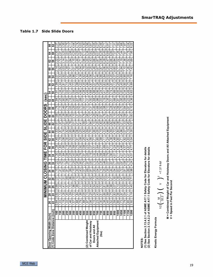
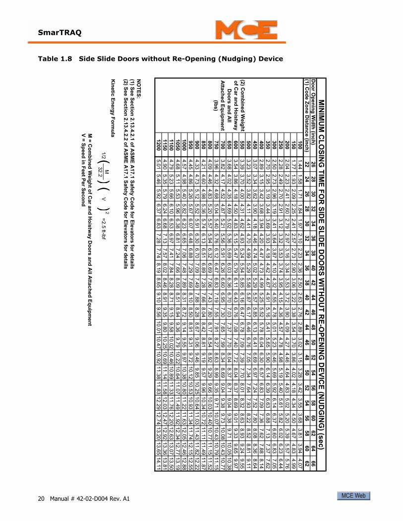
18 Manual # 42-02-D004 Rev. A1
SmarTRAQ Adjustments
Table 1.7 Side Slide Doors
26
28
30
32
34
36
38
40
42
44
46
48
50
52
54
56
58
60
62
64
66
(1)
Co
de Z
on
e D
ista
nce (
inch
)22
24
26
28
30
32
34
36
38
40
42
44
46
48
50
52
54
56
58
60
62
100
0.8
40.9
20.9
91.0
71.1
51.2
21.3
01.3
81.4
51.5
31.6
11.6
81.7
61.8
41.9
11.9
92.0
72.1
42.2
22.3
02.3
7
150
1.0
31.1
21.2
21.3
11.4
11.5
01.5
91.6
91.7
81.8
71.9
72.0
62.1
52.2
52.3
42.4
42.5
32.6
22.7
22.8
12.9
0
200
1.1
91.3
01.4
11.5
11.6
21.7
31.8
41.9
52.0
62.1
62.2
72.3
82.4
92.6
02.7
02.8
12.9
23.0
33.1
43.2
53.3
5
250
1.3
31.4
51.5
71.6
91.8
11.9
42.0
62.1
82.3
02.4
22.5
42.6
62.7
82.9
03.0
23.1
43.2
73.3
93.5
13.6
33.7
5
300
1.4
61.5
91.7
21.8
61.9
92.1
22.2
52.3
92.5
22.6
52.7
82.9
23.0
53.1
83.3
13.4
53.5
83.7
13.8
43.9
84.1
1
350
1.5
71.7
21.8
62.0
02.1
52.2
92.4
32.5
82.7
22.8
63.0
13.1
53.2
93.4
33.5
83.7
23.8
64.0
14.1
54.2
94.4
4
400
1.6
81.8
41.9
92.1
42.3
02.4
52.6
02.7
52.9
13.0
63.2
13.3
73.5
23.6
73.8
33.9
84.1
34.2
84.4
44.5
94.7
4
450
1.7
91.9
52.1
12.2
72.4
32.6
02.7
62.9
23.0
83.2
53.4
13.5
73.7
33.8
94.0
64.2
24.3
84.5
44.7
14.8
75.0
3
500
1.8
82.0
52.2
22.3
92.5
72.7
42.9
13.0
83.2
53.4
23.5
93.7
63.9
34.1
14.2
84.4
54.6
24.7
94.9
65.1
35.3
0
550
1.9
72.1
52.3
32.5
12.6
92.8
73.0
53.2
33.4
13.5
93.7
73.9
54.1
34.3
14.4
94.6
64.8
45.0
25.2
05.3
85.5
6
600
2.0
62.2
52.4
42.6
22.8
13.0
03.1
93.3
73.5
63.7
53.9
44.1
24.3
14.5
04.6
84.8
75.0
65.2
55.4
35.6
25.8
1
650
2.1
52.3
42.5
42.7
32.9
33.1
23.3
23.5
13.7
13.9
04.1
04.2
94.4
94.6
84.8
85.0
75.2
75.4
65.6
65.8
56.0
5
700
2.2
32.4
32.6
32.8
33.0
43.2
43.4
43.6
43.8
54.0
54.2
54.4
54.6
64.8
65.0
65.2
65.4
65.6
75.8
76.0
76.2
7
750
2.3
02.5
12.7
22.9
33.1
43.3
53.5
63.7
73.9
84.1
94.4
04.6
14.8
25.0
35.2
45.4
55.6
65.8
76.0
86.2
96.4
9
800
2.3
82.6
02.8
13.0
33.2
53.4
63.6
83.8
94.1
14.3
34.5
44.7
64.9
85.1
95.4
15.6
35.8
46.0
66.2
86.4
96.7
1
850
2.4
52.6
82.9
03.1
23.3
53.5
73.7
94.0
14.2
44.4
64.6
84.9
15.1
35.3
55.5
85.8
06.0
26.2
56.4
76.6
96.9
1
900
2.5
22.7
52.9
83.2
13.4
43.6
73.9
04.1
34.3
64.5
94.8
25.0
55.2
85.5
15.7
45.9
76.2
06.4
36.6
66.8
97.1
1
950
2.5
92.8
33.0
73.3
03.5
43.7
74.0
14.2
44.4
84.7
24.9
55.1
95.4
25.6
65.8
96.1
36.3
76.6
06.8
47.0
77.3
1
1000
2.6
62.9
03.1
43.3
93.6
33.8
74.1
14.3
54.6
04.8
45.0
85.3
25.5
65.8
16.0
56.2
96.5
36.7
77.0
27.2
67.5
0
1050
2.7
32.9
73.2
23.4
73.7
23.9
74.2
14.4
64.7
14.9
65.2
15.4
55.7
05.9
56.2
06.4
56.6
96.9
47.1
97.4
47.6
8
1100
2.7
93.0
43.3
03.5
53.8
14.0
64.3
14.5
74.8
25.0
75.3
35.5
85.8
46.0
96.3
46.6
06.8
57.1
07.3
67.6
17.8
7
1150
2.8
53.1
13.3
73.6
33.8
94.1
54.4
14.6
74.9
35.1
95.4
55.7
15.9
76.2
36.4
96.7
57.0
07.2
67.5
27.7
88.0
4
1200
2.9
23.1
83.4
53.7
13.9
84.2
44.5
14.7
75.0
45.3
05.5
75.8
36.1
06.3
66.6
36.8
97.1
67.4
27.6
97.9
58.2
2
NO
TE
S:
(1)
See S
ecti
on
2.1
3.4
.2.1
of
AS
ME
A17.1
Safe
ty C
od
e f
or
Ele
vato
rs f
or
deta
ils
(2)
See S
ecti
on
2.1
3.4
.2.2
of
AS
ME
A17.1
Safe
ty C
od
e f
or
Ele
vato
rs f
or
deta
ils
Kin
eti
c E
nerg
y F
orm
ula M
= C
om
bin
ed
Weig
ht
of
Car
an
d H
ois
tway D
oo
rs a
nd
All A
ttach
ed
Eq
uip
men
t
V =
Sp
eed
in
Feet
Per
Seco
nd
(2)
Co
mb
ined
Weig
ht
of
Car
an
d H
ois
tway
Do
ors
an
d A
ll
Att
ach
ed
Eq
uip
men
t
(lb
s)
MIN
IMU
M C
LO
SIN
G T
IME
FO
R S
IDE
SL
IDE
DO
OR
S
(se
c)
Do
or
Op
en
ing
Wid
th (
inch
)
M2
32.2
()
1/2
=7.3
7 ft-
lbf
)(
V
19
SmarTRAQ
Table 1.8 Side Slide Doors without Re-Opening (Nudging) Device
26
28
30
32
34
36
38
40
42
44
46
48
50
52
54
56
58
60
62
64
66
(1) C
od
e Z
on
e D
ista
nce (in
ch
)22
24
26
28
30
32
34
36
38
40
42
44
46
48
50
52
54
56
58
60
62
100
1.4
41.5
81.7
11.8
41.9
72.1
02.2
32.3
62.5
02.6
32.7
62.8
93.0
23.1
53.2
83.4
23.5
53.6
83.8
13.9
44.0
7
150
1.7
71.9
32.0
92.2
52.4
12.5
72.7
32.9
03.0
63.2
23.3
83.5
43.7
03.8
64.0
24.1
84.3
44.5
04.6
74.8
34.9
9
200
2.0
42.2
32.4
12.6
02.7
92.9
73.1
63.3
43.5
33.7
23.9
04.0
94.2
74.4
64.6
44.8
35.0
25.2
05.3
95.5
75.7
6
250
2.2
82.4
92.7
02.9
13.1
23.3
23.5
33.7
43.9
54.1
54.3
64.5
74.7
84.9
85.1
95.4
05.6
15.8
26.0
26.2
36.4
4
300
2.5
02.7
32.9
63.1
93.4
13.6
43.8
74.1
04.3
24.5
54.7
85.0
15.2
35.4
65.6
95.9
26.1
46.3
76.6
06.8
37.0
5
350
2.7
02.9
53.1
93.4
43.6
93.9
34.1
84.4
24.6
74.9
15.1
65.4
15.6
55.9
06.1
46.3
96.6
36.8
87.1
37.3
77.6
2
400
2.8
93.1
53.4
23.6
83.9
44.2
04.4
74.7
34.9
95.2
55.5
25.7
86.0
46.3
06.5
76.8
37.0
97.3
67.6
27.8
88.1
4
450
3.0
73.3
43.6
23.9
04.1
84.4
64.7
45.0
25.2
95.5
75.8
56.1
36.4
16.6
96.9
77.2
47.5
27.8
08.0
88.3
68.6
4
500
3.2
33.5
23.8
24.1
14.4
14.7
04.9
95.2
95.5
85.8
76.1
76.4
66.7
67.0
57.3
47.6
47.9
38.2
28.5
28.8
19.1
1
550
3.3
93.7
04.0
04.3
14.6
24.9
35.2
45.5
45.8
56.1
66.4
76.7
87.0
97.3
97.7
08.0
18.3
28.6
38.9
39.2
49.5
5
600
3.5
43.8
64.1
84.5
04.8
35.1
55.4
75.7
96.1
16.4
36.7
67.0
87.4
07.7
28.0
48.3
78.6
99.0
19.3
39.6
59.9
7
650
3.6
84.0
24.3
54.6
95.0
25.3
65.6
96.0
36.3
66.7
07.0
37.3
77.7
08.0
48.3
78.7
19.0
49.3
89.7
110.0
510.3
8
700
3.8
24.1
74.5
24.8
75.2
15.5
65.9
16.2
66.6
06.9
57.3
07.6
57.9
98.3
48.6
99.0
49.3
89.7
310.0
810.4
310.7
7
750
3.9
64.3
24.6
85.0
45.4
05.7
66.1
26.4
76.8
37.1
97.5
57.9
18.2
78.6
38.9
99.3
59.7
110.0
710.4
310.7
911.1
5
800
4.0
94.4
64.8
35.2
05.5
75.9
46.3
26.6
97.0
67.4
37.8
08.1
78.5
48.9
29.2
99.6
610.0
310.4
010.7
711.1
511.5
2
850
4.2
14.6
04.9
85.3
65.7
46.1
36.5
16.8
97.2
87.6
68.0
48.4
28.8
19.1
99.5
79.9
610.3
410.7
211.1
111.4
911.8
7
900
4.3
34.7
35.1
25.5
25.9
16.3
06.7
07.0
97.4
97.8
88.2
88.6
79.0
69.4
69.8
510.2
510.6
411.0
311.4
311.8
212.2
2
950
4.4
54.8
65.2
65.6
76.0
76.4
86.8
87.2
97.6
98.1
08.5
08.9
19.3
19.7
210.1
210.5
310.9
311.3
411.7
412.1
512.5
5
1000
4.5
74.9
85.4
05.8
26.2
36.6
57.0
67.4
87.8
98.3
18.7
29.1
49.5
59.9
710.3
810.8
011.2
211.6
312.0
512.4
612.8
8
1050
4.6
85.1
15.5
35.9
66.3
86.8
17.2
47.6
68.0
98.5
18.9
49.3
69.7
910.2
210.6
411.0
711.4
911.9
212.3
412.7
713.1
9
1100
4.7
95.2
35.6
66.1
06.5
36.9
77.4
17.8
48.2
88.7
19.1
59.5
810.0
210.4
610.8
911.3
311.7
612.2
012.6
313.0
713.5
0
1150
4.9
05.3
55.7
96.2
46.6
87.1
37.5
78.0
28.4
68.9
19.3
59.8
010.2
510.6
911.1
411.5
812.0
312.4
712.9
213.3
613.8
1
1200
5.0
15.4
65.9
26.3
76.8
37.2
87.7
48.1
98.6
59.1
09.5
610.0
110.4
710.9
211.3
811.8
312.2
912.7
413.2
013.6
514.1
1
NO
TE
S:
(1) S
ee S
ectio
n 2
.13.4
.2.1
of A
SM
E A
17.1
Safe
ty C
od
e fo
r Ele
vato
rs fo
r deta
il s
(2) S
ee S
ectio
n 2
.13.4
.2.2
of A
SM
E A
17.1
Safe
ty C
od
e fo
r Ele
vato
rs fo
r deta
ils
Kin
etic
En
erg
y F
orm
ulaM
= C
om
bin
ed
Weig
ht o
f Car a
nd
Ho
istw
ay D
oo
rs a
nd
All A
ttach
ed
Eq
uip
men
t
V =
Sp
eed
in F
eet P
er S
eco
nd
(2) C
om
bin
ed
Weig
ht
of C
ar a
nd
Ho
istw
ay
Do
ors
an
d A
ll
Atta
ch
ed
Eq
uip
men
t
(lbs)
MIN
IMU
M C
LO
SIN
G T
IME
FO
R S
IDE
SL
IDE
DO
OR
S W
ITH
OU
T R
E-O
PE
NIN
G D
EV
ICE
(NU
DG
ING
) (se
c)
Do
or O
pen
ing
Wid
th (in
ch
)
M2
32.2
V)
=2.5
ft-lbf
1/2(
)(
20 Manual # 42-02-D004 Rev. A1
Troubleshooting
TroubleshootingThis section is divided into two topics:
• Helpful Hints: Real world information about door operator functions that can help with adjustment, repair, or troubleshooting.
• Functional Troubleshooting: Specific information to help the installer overcome most common problems encountered during SmarTRAQ installation.
Helpful HintsHelpful Hints describes:
• Door Open and Door Close Logic• Self-Holding• Door Close Limit and Door Open Limit• Limit #1 and Limit #2• Car Door Bumpers• Belt and Chain Tension• Motor Terminal Designation• Learn Operation• Changing Parameters• Stall Protection• Door Open and Door Close Protection Timers• Temporary Operation for Evaluation• Encoder Cable• Auto Reset• Control Priority• Control Status
Door Open and Door Close LogicSmarTRAQ is designed to allow power to be applied indefinitely to hold doors open or closed. With some controller designs, Otis comes to mind, a single relay or single family of relays is energized to open doors and then that same relay or relays are de-energized to close doors.
Self-HoldingHold open torque parameter “Co” is used to hold doors open and hold close torque parameter “Cc” is used to hold doors closed. This feature is especially useful if doors tend to drift partially closed, when open command is removed, when fully open or drift partially open when fully closed, when close command is removed. Using the Co and Cc parameters, SmarTRAQ is self-holding in full open or full close positions. (If doors drift closed when controller power is removed, then some sort of door hold open device may be required.)
Door Close Limit and Door Open LimitDCL and DOL are generated electronically when doors reach full close position or full open position, up against the bumpers, and current increases. After an unobstructed “learn opera-tion”, SmarTRAQ knows the difference between an obstruction and full open or full close posi-tion. DCL and DOL can only be generated within approximately the last one half inch of travel.
DOL and DCL have loss of power memory. When power is restored after a power loss, DCL will be re-established if doors were fully closed or DOL will be re-established if doors were fully open prior to power interruption.
21

SmarTRAQ
Limit #1 and Limit #2Limit #1 and Limit #2 are outputs from SmarTRAQ to the elevator controller. Either or both may be used to provide a variety of features including:
• Bypass retiring cam contact for controllers that use a retiring cam contact paralleled with a door position contact in door open logic
• Limited door reversal
• Advance start
Either Limit output may be programmed to activate anywhere between the full open and full close positions in both directions of travel. Each limit relay is provided with a form “C” contact that can be wired in a Normal Open or Normal Closed configuration. Both Limits have loss-of-power memory of On or Off status. Position memory is restored with the first full open door operation after power is restored.
Limit #1 is adjusted using the “LP” parameter.
Limit #2 is adjusted using the “LC” parameter.
CautionLimit #1 and Limit #2 must NOT be used to remove the door open and door close signal to SmarTRAQ. Doors must reach full open position and generate DOL electronically before removing the door open signal to the drive. Doors must reach full close position and gener-ate DCL electronically before removing the door close signal to the drive.
Car Door BumpersAll door operators must have both open and close bumpers. For proper operation, it is very important that car door bumpers are in good shape and securely mounted. Doors must stop on the open door bumper at full open position and on the close door bumper in full closed position. It is also very important that car doors stop on car door bumpers at every floor. Make sure hoistway door bumpers, if provided, do not stop car doors before car door bumpers.
Belt and Chain TensionBelts and chains must be tensioned properly, much tighter than normally expected. Belts must be in good shape. If after tension adjustment, belts still slip, they must be replaced. Secondary drive V-belts on MAC and Dover Door Operators tend to slip, this is why GAL and ECI use a chain as part of their design. The belt type should be changed from a simple, inexpensive V-belt to a more robust grip type V-belt with notches and additional traction provided on the sides of the belt. With closed-loop control, power transmission from the motor/encoder to doors must have absolute minimum elasticity, slack, and slippage.
22 Manual # 42-02-D004 Rev. A1

Troubleshooting
Motor Terminal DesignationThe motor has six terminals, but only four are used. Looking down at the motor from above with the shaft facing you: Starting on the left side closest to the shaft, the first terminal is “W”, then “V” in the middle, and “U” toward the encoder end. The middle terminal on the right side is “N.”
Learn OperationThe “learn operation” can only take place if the drive thinks the doors are fully closed (indicated when “PL” is displayed and the DCL LED is lighted). Hold Open/Close switch in close direction until “PL” is displayed and the DCL LED is lighted. Reduce “C1” parameter if torque is too high in open direction. Reduce “C3” parameter if torque is too high in close direction.
Changing ParametersParameters can only be changed if the drive thinks the doors are closed. If pressing the “Enter” button changes parameter value then the doors are closed. If pressing the “Enter” button does not change the parameter, then holding the Open/Close switch until the doors are fully closed and, at the same time, pressing the “Enter” button allows you to change the parameter.
Stall ProtectionSmarTRAQ has built-in stall protection in both directions of travel. In the open direction, an internal stall timer is set for one minute. If the door open signal to the drive is activated for more than one minute, the drive will automatically shut off. The drive will not respond until the signal is removed and reapplied or the opposite direction signal is applied. The stall timer for the close direction operates in a similar manner, but is set for two minutes.
Door Open and Door Close Protection TimersDoor open and door close protection timers must be set longer than it takes the doors to open or close at the lowest speeds (first open operation after restoring power and nudging close). Door open and close protection timers are set at the elevator Controller.
Temporary Operation for EvaluationTemporary operation for evaluation can be accomplished easily by removing the existing motor and setting it aside without removing the wires. Rest the drive on the car top. Install the new motor and wire the motor and encoder to the drive. Wire the drive to a power cord with a plug. (Be certain that the outlet is providing the correct 120, 208, or 240VAC operating power and that the inverter drive input wiring has been properly set for that volt-age.) Plug the power cord into the car top electrical outlet. Turn on power and adjust the door operator. Once you’re satisfied that everything is OK, either return the door operator to its orig-inal condition or remove the old motor and temporary wiring, mount the drive, wire the new motor and encoder to the drive and wire the drive to the controller.
Note
MCE does NOT recommend permanently wiring the drive to the car lighting power circuit.
23
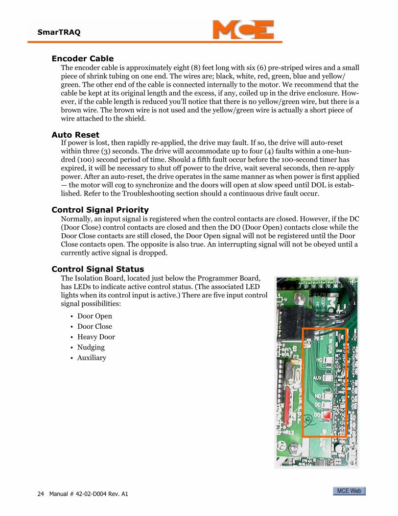
SmarTRAQ
Encoder CableThe encoder cable is approximately eight (8) feet long with six (6) pre-striped wires and a small piece of shrink tubing on one end. The wires are; black, white, red, green, blue and yellow/green. The other end of the cable is connected internally to the motor. We recommend that the cable be kept at its original length and the excess, if any, coiled up in the drive enclosure. How-ever, if the cable length is reduced you’ll notice that there is no yellow/green wire, but there is a brown wire. The brown wire is not used and the yellow/green wire is actually a short piece of wire attached to the shield.
Auto ResetIf power is lost, then rapidly re-applied, the drive may fault. If so, the drive will auto-reset within three (3) seconds. The drive will accommodate up to four (4) faults within a one-hun-dred (100) second period of time. Should a fifth fault occur before the 100-second timer has expired, it will be necessary to shut off power to the drive, wait several seconds, then re-apply power. After an auto-reset, the drive operates in the same manner as when power is first applied — the motor will cog to synchronize and the doors will open at slow speed until DOL is estab-lished. Refer to the Troubleshooting section should a continuous drive fault occur.
Control Signal PriorityNormally, an input signal is registered when the control contacts are closed. However, if the DC (Door Close) control contacts are closed and then the DO (Door Open) contacts close while the Door Close contacts are still closed, the Door Open signal will not be registered until the Door Close contacts open. The opposite is also true. An interrupting signal will not be obeyed until a currently active signal is dropped.
Control Signal StatusThe Isolation Board, located just below the Programmer Board, has LEDs to indicate active control status. (The associated LED lights when its control input is active.) There are five input control signal possibilities:
• Door Open
• Door Close
• Heavy Door
• Nudging
• Auxiliary
24 Manual # 42-02-D004 Rev. A1
Troubleshooting
Functional TroubleshootingTroubleshooting examples are provided in “installation order” specifically to help the installer through the process. The “top twelve” technical support are also listed and referenced below. (If you are looking at this on-line (in a pdf file), just click on a top twelve topic to jump to that spot in the guide. If there are multiple entries, just click on the page number.
• Closing torque too high: Please refer to “Torque Adjustment” on page 32.• Closing torque too low: Please refer to “Torque Adjustment” on page 32.• Opening torque too high: Please refer to “Torque Adjustment” on page 32.• Opening torque too low: Please refer to “Torque Adjustment” on page 32.• No DCL: Refer to page 11, page 21, page 26, and page 28.• No DOL: Refer to page 11, page 21, page 29.• Cannot learn: Refer to page 11, page 27.• Cannot change parameters: Refer to page 15, page 27.• Doors drift close: Refer to page 21.• Doors drift open: Refer to page 21.• Cut encoder cable, no yellow/green wire: Refer to page 24.• Car door bumpers: Refer to page 22.
Power UpWhen power is applied to the SmarTRAQ Drive, the GREEN LED (DLL-V) on the main board is ON. The RED LED (DL2-R) on the main board should remain OFF.
The Programmer board will display a SINGLE BAR and REMOTE or LOCAL led is ON.
IF… Programmer display and Remote or Local LEDs are off and green LED on main board is on:
1. Check connections between main board and programmer board.2. Verify connectors are inserted correctly.
IF… Programmer display and Remote or Local LEDs are off and green LED on main board is off:
1. Confirm correct AC voltage provided to terminals. 2. Check all connections between AC voltage supply from controller to transformer in the
drive.
3. Confirm main line disconnect switch is ON.
4. Confirm all fast connectors inside drive are inserted correctly.
5. Confirm that no pieces of conductive material dropped onto boards.
6. Check fuses in drive.
IF… The red LED on main board is on:
1. Confirm input voltage is correct. 2. Confirm that no pieces of conductive material dropped onto boards.
3. Confirm all fast connectors inside drive are inserted correctly.
25

SmarTRAQ
Motor SynchronizationIf power up is successful, the door operator is ready to synchronize the motor.
1. Select LOCAL on the programming board.2. Press Open/Close switch to provide a momentary OPEN or CLOSE command.
The motor will cog to synchronize the rotor. Time required for this operation varies, but should be less than 10 seconds. When synchronization is complete, the door operator is ready to accept commands.
IF… Motor does not cog and synchronize:
1. Confirm motor wires are connected correctly to main board at connector TB-2.2. Confirm encoder wires are connected correctly to main board at connector TB-3.
3. Confirm programming board is connected correctly to main board and TB-8/J2 connec-tors are inserted correctly.
IF… Motor cogs indefinitely, drive shuts down (after two minutes), and red LED is ON:
1. Confirm ENCODER WIRES are connected correctly to main board at connector TB-3, especially green wire on terminal 9.
2. Open rear cover of motor and check all connectors to make sure they are inserted cor-rectly.
First Door ClosingIf motor synchronization was successful, the next step is to CLOSE the doors. This is because programming board parameters can only be accessed after the drive detects FULL DOOR CLOSE and the DCL signal is ACTIVE. Even though doors were closed by hand, IT IS ALWAYS NECESSARY to give a close command until DCL is activated. When the first full door close position is detected and DCL is generated, “PL” will be displayed on the programmer board. Parameters can now be accessed.
IF… Motor does not rotate properly, makes noise, or vibrates:
1. Confirm encoder wires are connected correctly to main board at connector TB-3.2. Open rear cover of motor and check that all connectors are inserted correctly.
3. Confirm that the shielded wire of the encoder cable does not touch any metal part of the enclosure or door operator.
4. If previous steps are OK, cycle power and repeat procedure.
IF… On the close command, doors move in open direction, brake, and drive resets:
1. Problems in start-up procedure were encountered and the drive reset. Procedure must be repeated starting with Motor Synchronization.
2. If problems persist, cycle power and repeat entire procedure.
IF… Doors reach close position but the DCL signal is not generated, there is probably slip-page somewhere in the mechanical transmission system and the motor is still turning while the doors are stopped:
1. Check belt tension. Tighten as necessary to prevent slippage. Grip-notch type belts may be required.
26 Manual # 42-02-D004 Rev. A1
Troubleshooting
2. If tightening the belt is not effective, stop the motor by hand (minimal amount of pres-sure is usually required) so that DCL is generated. Set a lower value for “C3” and “Cc” (reduces full close torque to reduce slippage).
IF… DCL is generated but PL is not displayed:
1. Check connections between main board and programmer board.
Learn ProcessIf the first closing of the doors was completed correctly and DCL is active, the learning process can be executed:
1. With “PL” displayed, press ENTER button once; a number will be displayed.2. Press ENTER again. “PL” will be displayed.
3. Press minus (-) button to display “Lr”, then press ENTER button to start the learn pro-cess.
Doors should reach full open position, then reverse and reach full close position. During this process, it is important that doors open to their maximum width and close completely (includ-ing additional turns the motor may make when doors are fully closed).
Completing the learn process is required for proper operation.
IF… You press ENTER and no numbers are displayed:
1. More than likely, DCL was not generated. Give close command again until DCL is gener-ated.
IF… During opening, doors stop and reverse before reaching full open, the “C1” parameter may be set too low or there is too much friction:
1. Ensure that doors move freely.2. If possible, access programmer board and change value of parameter “C1” (DCL must be
generated) and repeat learning process.
3. If it is not possible to access the programmer board and change parameter “C1” because DCL was not generated, cycle power and repeat procedure beginning with learn process.
4. Change the value of “C1” and repeat learning process again.
IF… During opening, doors reach full open and push up against bumper but do not reverse, there is probably slippage somewhere in the mechanical transmission system and the motor is still turning while doors are stopped:
1. If possible, stop motor by hand. Doors should now reverse and close. If not, turn off power and attempt to open doors again.
2. Check the mechanical transmission system, tighten belts.
3. Repeat start up procedure. If problem persists, cycle power and repeat procedure begin-ning with first closing of the doors. After this, reduce value of “C1” and “Co” and execute learning process.
4. Repeat until correct values for “C1” and “Co” are found.
27

SmarTRAQ
IF… During opening, doors reach full open, push up against bumper, and stop with red LED on, a fault condition occurred (most likely due to low AC input voltage):
1. Check AC voltage using a voltmeter. Check voltage continuously during opening, espe-cially when doors push up against full open bumper. Voltage should not drop by more than 5% of nominal value (120/208/240VAC).
If voltage drop is excessive, and drive locks up, cycling power is required.
2. Excessive voltage drop may be due to a poor connection between source and drive. Wires may be undersized. Transformer in controller may be underrated.
3. As an experiment, temporarily use an alternate power source such as car lighting supply or a building convenience outlet circuit and repeat learn process. If problem is resolved in this manner, then a more robust power source from controller is required.
IF… During closing, doors reach full close, push up against bumper, and stop with red LED ON, follow steps for the problem above.
IF… During closing, doors stop before reaching full close and DCL is generated, “C3” value may be too small or there is too much friction:
1. Ensure doors move freely without excessive friction.2. If doors move freely, increase “C3” and repeat learn process.
IF… During closing, doors reach full close and push up against bumper but DCL is not gen-erated, there is probably slippage somewhere in the mechanical transmission system and the motor is still turning while doors are stopped:
1. If possible, try to stop motor by hand (only a small amount of pressure is usually required). The drive should now generate DCL. If not, turn off power.
2. Check mechanical linkage and transmission system. Tighten belts.
3. Repeat start up procedure. If problem persists, cycle power and repeat procedure through first closing of doors. After this, reduce value of “C3” and execute learn process.
4. Repeat this step until correct value for “C3” is found.
28 Manual # 42-02-D004 Rev. A1

Troubleshooting
First Open/Close After Cycling PowerAfter power is cycled, and doors are in full close position with DCL active, an OPEN command should be given using local command on programmer board. Doors will move in open direction at REDUCED SPEED. If a CLOSE command is given before DOL is generated, doors will move in close direction at REDUCED SPEED.
DOORS WILL MOVE AT REDUCED SPEED UNTIL FIRST DOL IS GENERATED.
This is necessary after having cycled power because the drive needs to determine a fixed refer-ence point for door position. (While the drive was turned off, the doors could have moved.) BE SURE CONTROLLER DOOR OPEN PROTECTION TIMER HAS SUFFICIENT TIME TO ALLOW FOR FIRST SLOW OPENING WITHOUT TRIPPING (set at elevator Controller).
IF… After reaching full open, DOL is generated but doors close at reduced speed:
1. Check value of “U3” parameter. Increase if set too low.2. Check that NUDGE speed was not inadvertently selected.
3. Check that HEAVY DOOR was not selected by controller.
4. Be sure learn process was performed correctly.
IF… After reaching full open, DOL is NOT generated and doors close at reduced speed, there is probably slippage somewhere in the mechanical transmission system and the motor is still turning when doors are stopped:
1. Tighten belts. Replace if worn. May need grip-notch type belts.2. If problem persists, decrease “C1” and “Co” parameters.
IF… DOL is generated before doors reach full open and doors stop:
1. Check for excessive friction or an obstacle in path of doors.2. If first step checks OK, increase “C1” parameter.
IF… After reaching full open, DOL is generated and doors close at correct speed but, when fully closed, DCL is not generated, there is probably slippage somewhere in the mechanical transmission system and the motor is still turning when doors are stopped:
1. Tighten belts. Replace if worn. May need grip-notch type belts. 2. Should problem persist, decrease “C3” parameter.
3. Should problem persist, repeat learn process.
IF… Red LED turns ON: Please refer to “During opening, doors stop and reverse before reaching full open, the “C1” parameter may be set too low or there is too much friction: ” on page 27.
IF… Doors move in close direction but stop before reaching full close and DCL is not gen-erated:
1. Check that there is no obstruction.2. Check that torque is sufficient to overcome friction.
3. If everything appears to be OK, increase “C3”.
29

SmarTRAQ
Opening and ClosingOpen and closing operations are accomplished by setting parameters for:
• High Speed Open and Close speeds using “U1/ U3”.
• Low Speed Open and Closing speeds using “U2/ U4”.
• Initial Open speed and distance using “U0” and “PL”.
• Open and Close acceleration using “A0/A2”.
• Open and Close deceleration and slowdown distance using “A1”and “P2/A3” and “P7”.
IF… Deceleration during opening or closing is too fast and doors jerk:
1. Parameter “A1” or “A3” is set too high. Reduce “A1” and “A3” and, consequently, reduce “P2” and “P7”.
2. Deceleration is too late and doors are approaching full open/close position too fast, safety braking action is activated, which suddenly reduces door speed. Reduce “P2” and “P7” and increase “A1” and “A3”.
3. These steps are usually sufficient to solve this problem. However, should problem per-sist and YOU ARE SURE YOU have tried all possible combinations of values for “A1”, “A3”, “P2”, and “P7”, change the value of the “Cb” parameter. Start with a value of 20, for example, and decrease gradually, checking each time until the problem is corrected.
“Cb” is a parameter which is usually kept at 00 value and is used to limit braking action of doors. We suggest it be used only if absolutely necessary and no other action is effective. Do not reduce value of “Cb” too much, otherwise there may not be enough braking action. It should be kept at the highest possible value that corrects the problem.
Setting “Cb” to 00 does not put a limit on braking torque.
IF… A high value for opening speed is set but doors move slower than expected:
1. Be sure DOL was detected.2. Acceleration parameter “A0” may be set too low.
3. Doors may be very heavy or there is excessive friction or mechanical ratio between motor and doors is low so that torque or power limit has been reached.
IF… A high value for closing speed is set but doors move slower than expected:
1. Be sure DOL was detected.2. Check that open acceleration parameter “A2” is not set too low.
3. Doors may be very heavy or there is excessive friction or mechanical gear ratio between motor and doors is low so that torque or power limit has been reached.
4. Value of “C3” parameter is too low, so that allowable closing torque is too low and not enough to move doors at desired speed. Increase value of “C3” gradually and check if this corrects problem.
30 Manual # 42-02-D004 Rev. A1

Troubleshooting
IF… Doors bump when opening or closing:
1. Slowdown points “P2” or “P7” are too near full open or close positions. Reduce “P2” or “P7”.
2. Deceleration values “A1” or “A3” are too low. Increase “A1” or “A3”.
3. Low speeds “U2” or “U4” are too high. Reduce “U2” or “U4”.
4. Opening and closing speeds “U1” or “U3” are too high and doors are heavy with low mechanical ratio so braking power required exceeds operator ratings.
5. “Cb” parameter is at a low value so braking action has been reduced too much.
IF… While opening or closing, especially during acceleration, doors stop and red LED turns ON:
1. Check AC input voltage. Be sure there is not excessive voltage drop, measured at termi-nals L1D and L2D, while opening or closing, especially during acceleration.
Note
Make certain that hoistway doors are engaged while checking for excessive voltage drop.
Reopening and Reclosing Reopening and reclosing are accomplished by setting parameters “Po”, “Pc”, “Pr”, “Ar”, “Ab”. During reopening, the function of parameters “P2” and “A1” is substituted for by “Po” and “Ar”. During reclosing (Fire Phase II “peek-a-boo” operation), the function of parameter “P7” is sub-stituted for by “Pc”. “Ab” regulates reversal braking.
Parameter “Pr” sets the transitional edge between “normal opening” and “reopening.” This parameter should be kept at 00 except in rare cases where mechanical ratio between motor and doors varies and dramatically changes speed.
IF… During reopening, doors bump, parameter “Po” is set too high and/or “Ar” is set too low.
1. Increase “Ar” and/or reduce “Po” until correct compromise is found.
IF… During reclosing, doors bump
1. Parameter “Pc” is set too high. Reduce “Pc”.
IF… During reopening, doors decelerate too rapidly, parameter “Po” is set too low and/or “Ar” is set too high.
1. Increase “Po” and/or reduce “Ar” until correct compromise is found.
IF… During reclosing, doors decelerate too rapidly, Parameter “Pc” is set too low:
1. Increase “Pc”
IF… During reopening or reclosing, deceleration point changes dramatically depending on position where reversal is commanded, parameter “Pr” has probably been set to a value other than 00 or has been set too high.
1. Reduce “Pr” until there are no inconsistencies. If not strictly necessary, set “Pr” at 00.
31

SmarTRAQ
IF… During reopening, the doors take too long to fully reopen:
1. Increase “Pr” incrementally. Remember that the more “Pr” is increased, the more the possibility of inconsistency while approaching full open.
IF… During reversals, doors stop and reverse too rapidly, producing mechanical vibrations and bumps:
1. Reduce “Ab” until reversal is smooth. 2. Check mechanical system and correct as required.
IF… During reversals, it takes too long for doors to stop and reverse:
1. Increase “Ab” until reversal is smooth.
Torque AdjustmentTorque adjustment is accomplished by setting parameters “C1”, “C3”, “Co”, “Cc”, and “Cb”.
Note
After torque adjustments are made, learn process must be repeated.
IF… In close direction, door close pressure is too high:
1. Reduce “C3” until door pressure is correct.
IF… In close direction, doors stop before reaching full close and DCL is NOT generated:
1. Check for an obstruction. 2. Check for friction in door system and, if necessary, increase “C3”.
IF… In close direction, DCL is generated slightly before doors are fully closed:
1. Make sure learn process was performed correctly.2. “C3” may be set too low. Increase “C3”.
IF… In open direction, DOL is generated slightly before doors are fully open:
1. Make sure learn process was performed correctly.2. “C1” may be set too low. Increase “C1”.
IF… After doors reach full open and DOL is generated, doors drift toward close direction:
1. If doors drift close, increase “Co”. The value of “Co” should be set to minimum necessary to keep doors from drifting close in order to minimize heating motor.
IF… After doors reach full close and DCL is generated, doors drift toward open position:
1. If doors drift open, increase “Cc”. The value of “Cc” should be set to minimum necessary to keep doors from drifting open in order to minimize heating motor.
32 Manual # 42-02-D004 Rev. A1
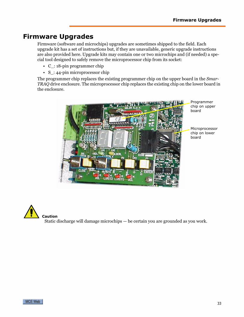
Firmware Upgrades
Firmware UpgradesFirmware (software and microchips) upgrades are sometimes shipped to the field. Each upgrade kit has a set of instructions but, if they are unavailable, generic upgrade instructions are also provided here. Upgrade kits may contain one or two microchips and (if needed) a spe-cial tool designed to safely remove the microprocessor chip from its socket:
• C_: 18-pin programmer chip
• S_: 44-pin microprocessor chip
The programmer chip replaces the existing programmer chip on the upper board in the Smar-TRAQ drive enclosure. The microprocessor chip replaces the existing chip on the lower board in the enclosure.
CautionStatic discharge will damage microchips — be certain you are grounded as you work.
Microprocessor chip on lower board
Programmer chip on upper board
33

SmarTRAQ
Replacing Microchips1. Make certain power to the SmarTRAQ inverter drive is shut off.
2. Remove the four screws securing the cover on the drive enclosure. Remove the cover. If the inverter drive is equipped with an ON/OFF switch, place it in the OFF position.
3. Remove the four screws securing the upper board to its stand-offs. Hold the stand-offs so that they do not unscrew from the lower board.
4. Using a small (preferably plastic) screwdriver, carefully lever the programmer chip out of its socket, raising first one end and then the other in stages to avoid damaging pins and socket.
5. Note that the chip must be correctly inserted in the socket with the notch at one end of the chip matched to the notch at one end of the socket. Insert the new chip gently, taking care not to bend the pins. Make certain the chip is completely seated in the socket.
6. Next, use the special tool included with this kit to carefully remove the microprocessor chip from its socket on the lower board. Be careful not to damage the socket or bend the pins on the chip.
7. Note that the microprocessor must be correctly inserted in the socket with the angled corner of the chip aligned with the angled corner of the socket. Insert the new micropro-cessor chip using EXTREME CARE not to bend the pins. If a pin is bent, the IC must be replaced. It is very easy to break a pin, so be careful. Make certain the microprocessor chip is completely seated in the socket.
8. Reinstall the upper board on its stand-offs. Take care not to overtighten the screws.
9. If the inverter drive is equipped with an ON/OFF switch, place it in the ON position. Reinstall the cover on the drive enclosure.
10. Restore power to the inverter drive. Refer to earlier sections of this guide for operating and adjusting instructions.
Stand-off
Upper board
Chip notchChip notch
Socket notch
Extraction tool jaw notchesCorrect insertion indicated by angled corner on socket and on chip
Extraction tool jaws
34 Manual # 42-02-D004 Rev. A1
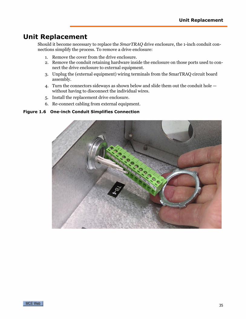
Unit Replacement
Unit ReplacementShould it become necessary to replace the SmarTRAQ drive enclosure, the 1-inch conduit con-nections simplify the process. To remove a drive enclosure:
1. Remove the cover from the drive enclosure.2. Remove the conduit retaining hardware inside the enclosure on those ports used to con-
nect the drive enclosure to external equipment.
3. Unplug the (external equipment) wiring terminals from the SmarTRAQ circuit board assembly.
4. Turn the connectors sideways as shown below and slide them out the conduit hole — without having to disconnect the individual wires.
5. Install the replacement drive enclosure.
6. Re-connect cabling from external equipment.
Figure 1.6 One-inch Conduit Simplifies Connection
35