smartsense365 installation guide rev. e - big ass...
TRANSCRIPT
INSTALLATION GUIDE
For help, call 1-877-BIG-FANS or visit www.BigAssFans.com
Big Ass Fan Company2348 Innovation DriveLexington, KY 405111-877-BIG-FANSwww.bigassfans.com
May be covered by one or more of the following United States patents:
6,244,821; 6,589,016; 6,817,835; 6,939,108; 7,252,478; 7,284,960; D587,799; D607,988; 7,654,798; D635,237; 7,934,907; D641,075; D642,674; 8,075,273; D650,893; 8,079,823; 8,147,182; 8,147,204; 8,152,453; 8,162,613; and other patents pending.
SmartSense365™ is a trademark of Delta T Corporation. All other trademarks used herein are the properties of their respective owners.
Installation Guide: Oct. 2013Rev. E
SMARTSENSE365™
ContentsIntroduction Thank You 1
About Big Ass Fans 1About the SmartSense365™ 1
Pre-Installation What’s in the Box 2Dimensions 3
Mounting the SmartSense365™ Overview 4SmartSense365 with Powerfoil®X2.0 and Powerfoil®X2.0Plus Fans 5SmartSense365 with Powerfoil®8 and Powerfoil®8Plus Fans 6Mounting the Remote Temperature Sensor 7Mounting the Wall Controller 8
Electrical Installation Electrical Installation Safety 9Power Guidelines 9Single Fan Installation for PowerfoilX2.0 and PowerfoilX2.0Plus Fans 10Multi-Fan Installation (Daisy Chaining) for PowerfoilX2.0 and PowerfoilX2.0Plus Fans 11Single Fan Installation for Powerfoil8 and Powerfoil8Plus Fans 12Multi-Fan Installation (Daisy Chaining) for Powerfoil8 and Powerfoil8Plus Fans 13Alternative Wiring Methods 14
Operating the SmartSense365 Starting and Stopping the Fan 15Modes of Operation 16
Programming the SmartSense365
Selecting a Mode 17Programming Winter Mode Maximum Fan Speed 17Programming Summer Mode Minimum and Maximum Temperatures 17Adjusting Manual Mode Fan Speed 17
Troubleshooting Wall Controller 18Remote Temperature Sensor 18
WWW.BIGASSFANS.COM ©2011 DELTA T CORP. DBA BIG ASS FANS ALL RIGHTS RESERVED
SMARTSENSE365™
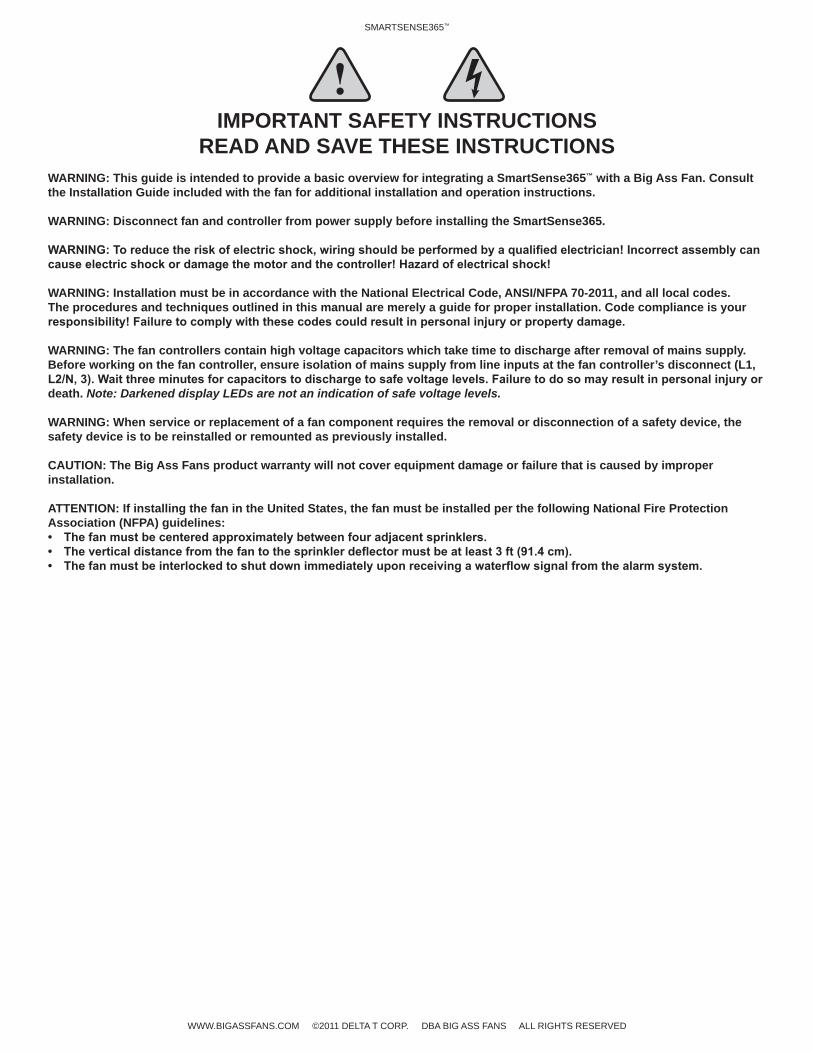
IMPORTANT SAFETY INSTRUCTIONSREAD AND SAVE THESE INSTRUCTIONS
WARNING: This guide is intended to provide a basic overview for integrating a SmartSense365™ with a Big Ass Fan. Consult the Installation Guide included with the fan for additional installation and operation instructions.
WARNING: Disconnect fan and controller from power supply before installing the SmartSense365.
WARNING: Installation must be in accordance with the National Electrical Code, ANSI/NFPA 70-2011, and all local codes. The procedures and techniques outlined in this manual are merely a guide for proper installation. Code compliance is your
WARNING: The fan controllers contain high voltage capacitors which take time to discharge after removal of mains supply. Before working on the fan controller, ensure isolation of mains supply from line inputs at the fan controller’s disconnect (L1,
death. Note: Darkened display LEDs are not an indication of safe voltage levels.
WARNING: When service or replacement of a fan component requires the removal or disconnection of a safety device, the safety device is to be reinstalled or remounted as previously installed.
CAUTION: The Big Ass Fans product warranty will not cover equipment damage or failure that is caused by improper installation.
ATTENTION: If installing the fan in the United States, the fan must be installed per the following National Fire Protection Association (NFPA) guidelines:
WWW.BIGASSFANS.COM ©2011 DELTA T CORP. DBA BIG ASS FANS ALL RIGHTS RESERVED
1SMARTSENSE365™
WWW.BIGASSFANS.COM ©2011 DELTA T CORP. DBA BIG ASS FAN CO. ALL RIGHTS RESERVED
Introduction
About the SmartSense365™
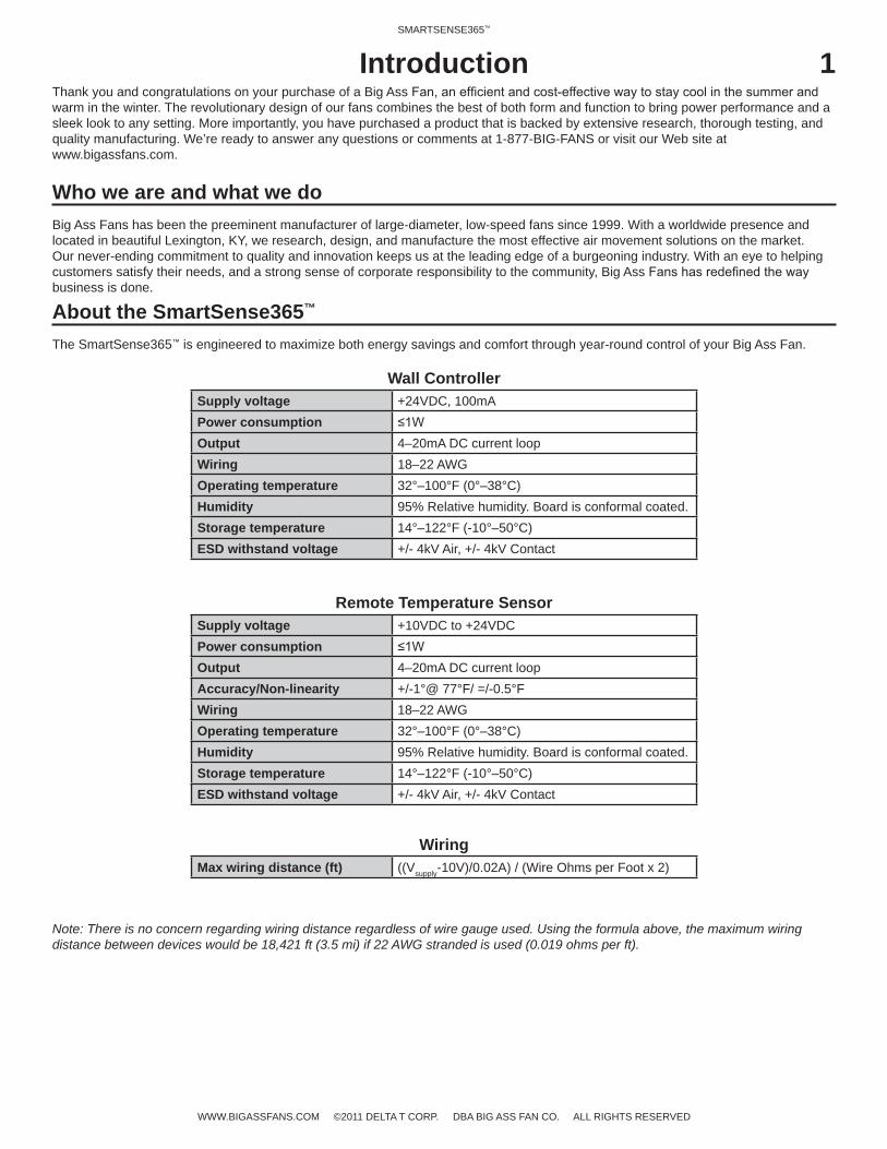
The SmartSense365™ is engineered to maximize both energy savings and comfort through year-round control of your Big Ass Fan.
Wall ControllerSupply voltage +24VDC, 100mAPower consumptionOutput 4–20mA DC current loopWiring 18–22 AWGOperating temperature 32°–100°F (0°–38°C)Humidity 95% Relative humidity. Board is conformal coated.Storage temperature 14°–122°F (-10°–50°C)ESD withstand voltage +/- 4kV Air, +/- 4kV Contact
Remote Temperature SensorSupply voltage +10VDC to +24VDCPower consumptionOutput 4–20mA DC current loopAccuracy/Non-linearity +/-1°@ 77°F/ =/-0.5°FWiring 18–22 AWGOperating temperature 32°–100°F (0°–38°C)Humidity 95% Relative humidity. Board is conformal coated.Storage temperature 14°–122°F (-10°–50°C)ESD withstand voltage +/- 4kV Air, +/- 4kV Contact
WiringMax wiring distance (ft) ((Vsupply-10V)/0.02A) / (Wire Ohms per Foot x 2)
Note: There is no concern regarding wiring distance regardless of wire gauge used. Using the formula above, the maximum wiring distance between devices would be 18,421 ft (3.5 mi) if 22 AWG stranded is used (0.019 ohms per ft).
Thank you and congratulations on your purchase of a Big Ass warm in the winter. The revolutionary design of our fans combines the best of both form and function to bring power performance and a sleek look to any setting. More importantly, you have purchased a product that is backed by extensive research, thorough testing, and quality manufacturing. We’re ready to answer any questions or comments at 1-877-BIG-FANS or visit our Web site at www.bigassfans.com.
Who we are and what we doBig Ass Fans has been the preeminent manufacturer of large-diameter, low-speed fans since 1999. With a worldwide presence and located in beautiful Lexington, KY, we research, design, and manufacture the most effective air movement solutions on the market. Our never-ending commitment to quality and innovation keeps us at the leading edge of a burgeoning industry. With an eye to helping customers satisfy their needs, and a strong sense of corporate responsibility to the community, Big Ass business is done.
2SMARTSENSE365™
WWW.BIGASSFANS.COM ©2011 DELTA T CORP. DBA BIG ASS FAN CO. ALL RIGHTS RESERVED
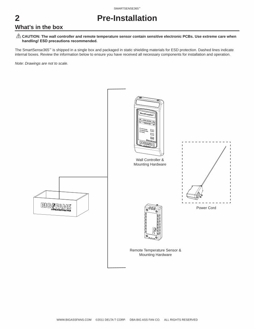
What’s in the boxCAUTION: The wall controller and remote temperature sensor contain sensitive electronic PCBs. Use extreme care when
The SmartSense365™ is shipped in a single box and packaged in static shielding materials for ESD protection. Dashed lines indicate internal boxes. Review the information below to ensure you have received all necessary components for installation and operation.
Note: Drawings are not to scale.
Pre-Installation
Wall Controller & Mounting Hardware
Remote Temperature Sensor & Mounting Hardware
Power Cord
3SMARTSENSE365™
WWW.BIGASSFANS.COM ©2011 DELTA T CORP. DBA BIG ASS FAN CO. ALL RIGHTS RESERVED
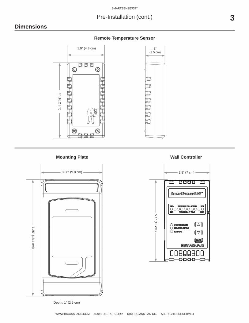
Dimensions
Wall Controller
Remote Temperature Sensor
4” (10.2 cm)
1.9” (4.8 cm) 1” (2.5 cm)
7.25” (18.4 cm)
3.86” (9.8 cm)
Depth: 1” (2.5 cm)
Mounting Plate
2.8” (7 cm)
5.1” (13 cm)
Pre-Installation (cont.)
SMARTSENSE365™
WWW.BIGASSFANS.COM ©2011 DELTA T CORP. DBA BIG ASS FAN CO. ALL RIGHTS RESERVED
Mounting the SmartSense365™
WARNING—TO REDUCE THE RISK OF FIRE, ELECTRIC SHOCK, OR INJURY TO PERSONS, OBSERVE THE FOLLOWING:
a. standards.
b. When cutting or drilling into a wall or ceiling, do not damage electrical wiring or other hidden utilities.
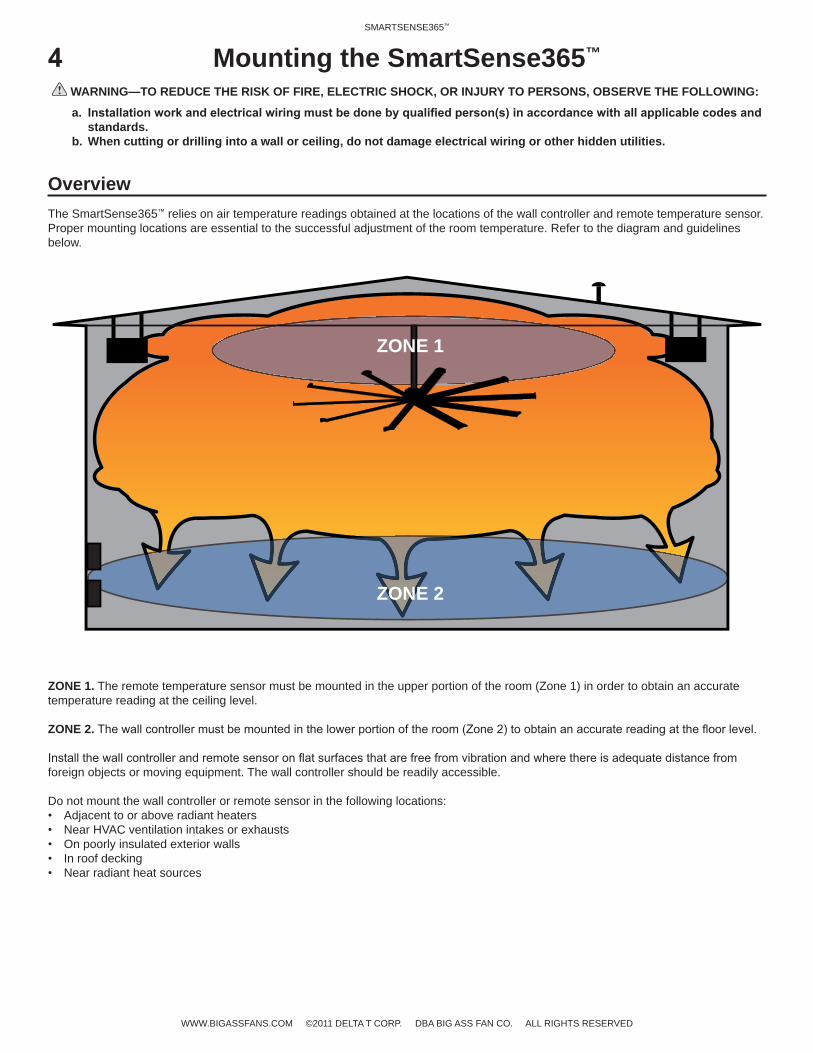
OverviewThe SmartSense365™ relies on air temperature readings obtained at the locations of the wall controller and remote temperature sensor. Proper mounting locations are essential to the successful adjustment of the room temperature. Refer to the diagram and guidelines below.
ZONE 1. The remote temperature sensor must be mounted in the upper portion of the room (Zone 1) in order to obtain an accurate temperature reading at the ceiling level.
ZONE 2.
foreign objects or moving equipment. The wall controller should be readily accessible.
Do not mount the wall controller or remote sensor in the following locations:Adjacent to or above radiant heatersNear HVAC ventilation intakes or exhaustsOn poorly insulated exterior wallsIn roof deckingNear radiant heat sources
ZONE 1
ZONE 2
5SMARTSENSE365™
WWW.BIGASSFANS.COM ©2011 DELTA T CORP. DBA BIG ASS FAN CO. ALL RIGHTS RESERVED
PU
RUN STOP FWD REV REM LOC
UH
MODE
PROGDATA
FWDREV
RUN STOPRESET
LOCALREM
F
MODE
FAN SPEED
THRESHOLD TEMPERATURE
10%
55°F
100%
100°F
WINTER MODE
SUMMER MODE
MANUAL
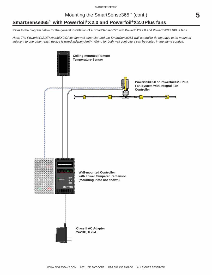
Mounting the SmartSense365™ (cont.)SmartSense365™ with Powerfoil®X2.0 and Powerfoil®X2.0Plus fansRefer to the diagram below for the general installation of a SmartSense365™ with Powerfoil®X2.0 and Powerfoil®X2.0Plus fans.
Note: The PowerfoilX2.0/PowerfoilX2.0Plus fan wall controller and the SmartSense365 wall controller do not have to be mounted adjacent to one other; each device is wired independently. Wiring for both wall controllers can be routed in the same conduit.
Class II AC Adapter
Wall-mounted Controller with Lower Temperature Sensor(Mounting Plate not shown)
Ceiling-mounted Remote Temperature Sensor
PowerfoilX2.0 or PowerfoilX2.0Plus Fan System with Integral Fan Controller
6SMARTSENSE365™
WWW.BIGASSFANS.COM ©2011 DELTA T CORP. DBA BIG ASS FAN CO. ALL RIGHTS RESERVED
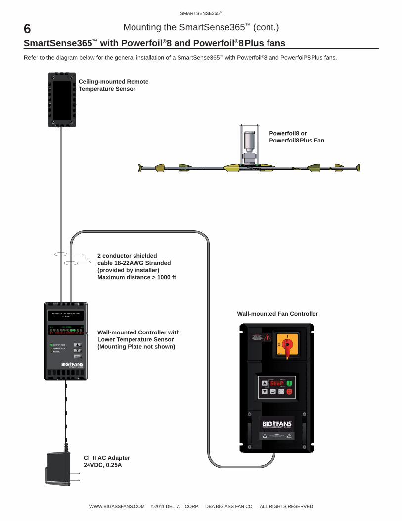
Mounting the SmartSense365™ (cont.)
SmartSense365™ with Powerfoil®8 and Powerfoil®8Plus fansRefer to the diagram below for the general installation of a SmartSense365™ with Powerfoil®8 and Powerfoil®8Plus fans.
Cl II AC Adapter
Wall-mounted Controller with Lower Temperature Sensor (Mounting Plate not shown)
Ceiling-mounted Remote Temperature Sensor
Powerfoil8 or Powerfoil8Plus Fan
2 conductor shielded cable 18-22AWG Stranded (provided by installer)Maximum distance > 1000 ft
Wall-mounted Fan Controller
MODE
FAN SPEED
THRESHOLD TEMPERATURE
10%
55°F
100%
100 °F
WINTER MODE
SUMMER MODE
MANUAL
AUTOMATIC DESTRATIFICATION SYSTEM
Wall mounted fan controller
M
R F
RUN
STOP
AUTO FWD
REV
WARNINGSafety Disconnect ONLY.
DO NOT use this disconnect to normally
operate the fan. Permanent damage may result!

7SMARTSENSE365™
WWW.BIGASSFANS.COM ©2011 DELTA T CORP. DBA BIG ASS FAN CO. ALL RIGHTS RESERVED
Mounting the SmartSense365™ (cont.)Mounting the remote temperature sensor
CAUTION: The wall controller and remote temperature sensor contain sensitive electronic PCBs. Use extreme care when
The remote temperature sensor is designed to be surface mounted in a location near the ceiling. Note: Wiring for the remote sensor must be completed at the same time the sensor is mounted.
To mount the remote temperature sensor, loosen the (4) screws and remove the cover from the remote sensor. Using the back of the sensor as a template, mark the (2) screw locations on the mounting surface. Loosely install the mounting screws on the mounting surface in the hole locations. Slide the remote over the screws, and then tighten the screws. Before reattaching the front cover, complete the wiring. See p. 9 for details and wiring diagrams. Note: The remote temperature sensor can be mounted in any orientation.
Mounting Screws
FrontCover Screws
Do not lose the rubber grommet during installation.
8SMARTSENSE365™
WWW.BIGASSFANS.COM ©2011 DELTA T CORP. DBA BIG ASS FAN CO. ALL RIGHTS RESERVED
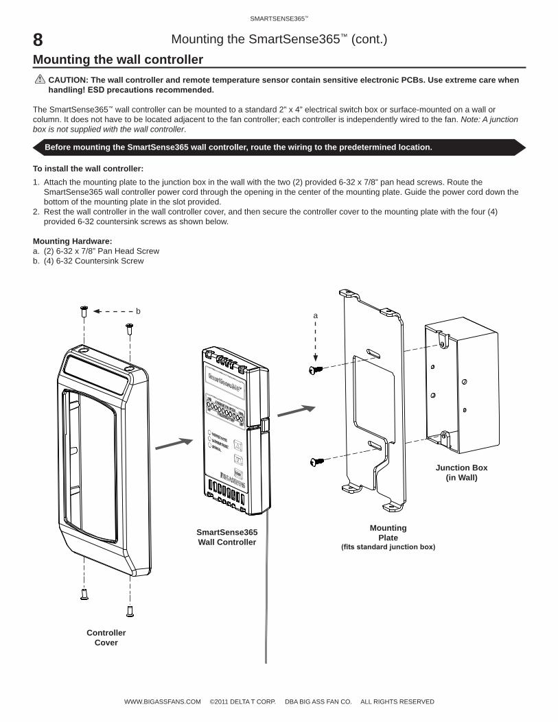
Mounting the wall controllerCAUTION: The wall controller and remote temperature sensor contain sensitive electronic PCBs. Use extreme care when
The SmartSense365™ wall controller can be mounted to a standard 2” x 4” electrical switch box or surface-mounted on a wall or column. It does not have to be located adjacent to the fan controller; each controller is independently wired to the fan. Note: A junction box is not supplied with the wall controller.
To install the wall controller:1. Attach the mounting plate to the junction box in the wall with the two (2) provided 6-32 x 7/8” pan head screws. Route the
SmartSense365 wall controller power cord through the opening in the center of the mounting plate. Guide the power cord down the bottom of the mounting plate in the slot provided.
2. Rest the wall controller in the wall controller cover, and then secure the controller cover to the mounting plate with the four (4) provided 6-32 countersink screws as shown below.
Mounting Hardware:a. (2) 6-32 x 7/8” Pan Head Screwb. (4) 6-32 Countersink Screw
Mounting the SmartSense365™ (cont.)
Before mounting the SmartSense365 wall controller, route the wiring to the predetermined location.
ab
Junction Box(in Wall)
SmartSense365Wall Controller
MountingPlate
ControllerCover

SMARTSENSE365™
WWW.BIGASSFANS.COM ©2011 DELTA T CORP. DBA BIG ASS FAN CO. ALL RIGHTS RESERVED
Electrical Installation
WARNING: Disconnect fan and controller from power supply before installing the SmartSense365™.
WARNING: Installation must be in accordance with the National Electrical Code, ANSI/NFPA 70-2011, and all local codes. The procedures and techniques outlined in this manual are merely a guide for proper installation. Code compliance is your
WARNING: The fan controllers contain high voltage capacitors which take time to discharge after removal of mains supply. Before working on the fan controller, ensure isolation of mains supply from line inputs at the fan controller’s disconnect (L1,
or death. Note: Darkened display LEDs are not an indication of safe voltage levels.
Power guidelines
Wall ControllerSupply voltage +24VDC, 100mAPower consumptionOutput 4–20mA DC current loopWiring 18–22 AWGESD withstand voltage +/- 4kV Air, +/- 4kV Contact
Remote Temperature SensorSupply voltage +10VDC to +24VDCOutput 4–20mA DC current loopAccuracy/Non-linearity +/-1°@ 77°F/ =/-0.5°FWiring 18–22 AWGESD withstand voltage +/- 4kV Air, +/- 4kV Contact
10SMARTSENSE365™
WWW.BIGASSFANS.COM ©2011 DELTA T CORP. DBA BIG ASS FAN CO. ALL RIGHTS RESERVED
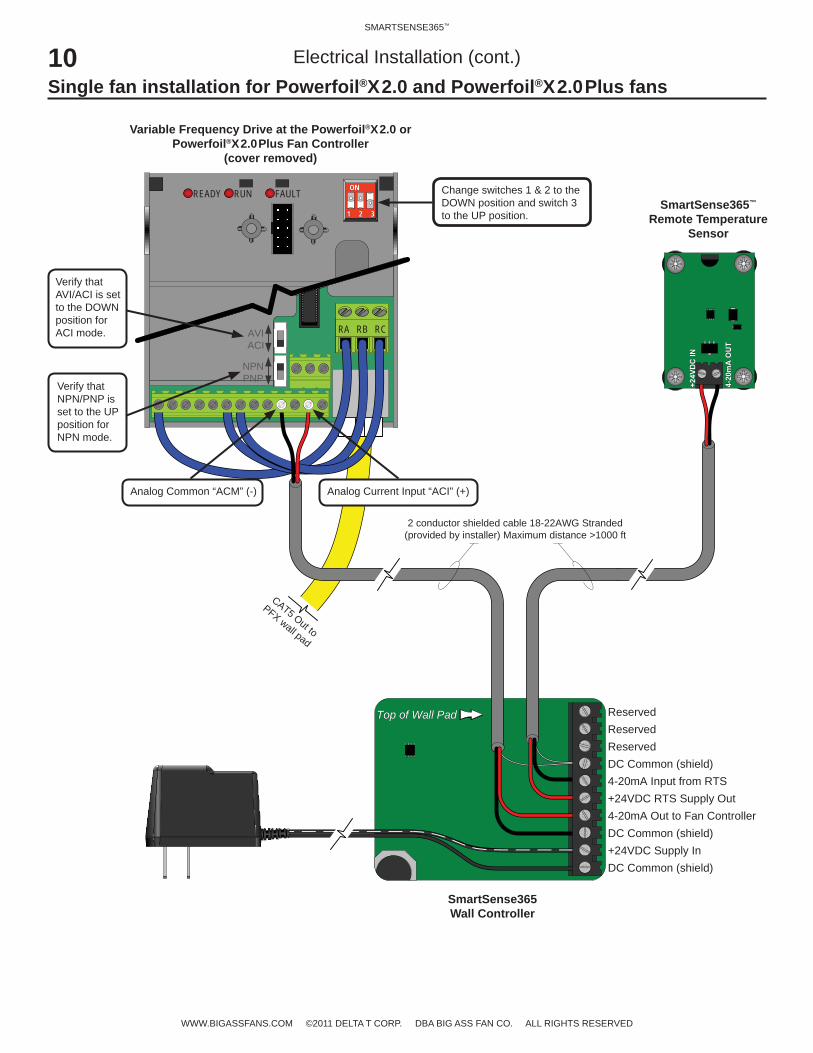
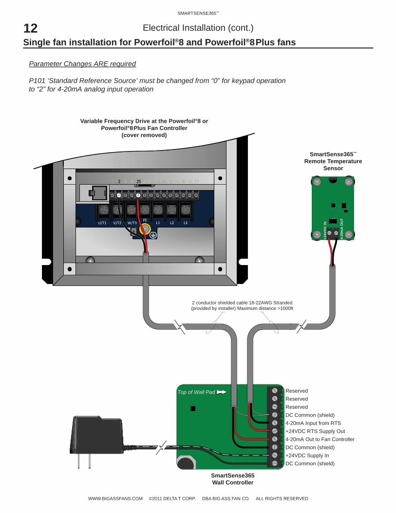
Top of Wall Pad
+24VDC Supply InDC Common (shield)
4-20mA Out to Fan ControllerDC Common (shield)
4-20mA Input from RTS+24VDC RTS Supply Out
ReservedDC Common (shield)
ReservedReserved
Top of Wall Pad
RA RB RCAVIACI
NPNPNP
CAT5 Out to
PFX wall pad
READY RUN FAULT
1 2 31 2 3
ONON
2 conductor shielded cable 18-22AWG Stranded(provided by installer) Maximum distance >1000 ft
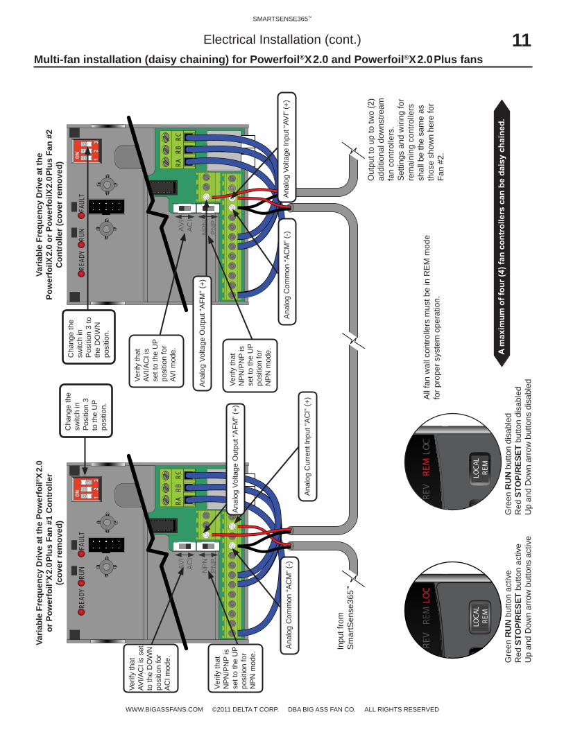
Verify that AVI/ACI is set to the DOWN position for ACI mode.
Verify that NPN/PNP is set to the UP position for NPN mode.
Analog Current Input “ACI” (+)Analog Common “ACM” (-)
Change switches 1 & 2 to the DOWN position and switch 3 to the UP position.
Variable Frequency Drive at the Powerfoil®X2.0 or Powerfoil®X2.0Plus Fan Controller
(cover removed)
SmartSense365™ Remote Temperature
Sensor
SmartSense365 Wall Controller
Single fan installation for Powerfoil®X2.0 and Powerfoil®X2.0Plus fansElectrical Installation (cont.)
11SMARTSENSE365™
WWW.BIGASSFANS.COM ©2011 DELTA T CORP. DBA BIG ASS FAN CO. ALL RIGHTS RESERVED
RA R
B R
CAV
IA
CI
NP
NP
NP
READ
YRU
NFA
ULT
1 2
3
1 2
3
ONON
RA R
B R
CA
VIAC
I
NP
NPN
P
READ
YRU
NFA
ULT
1 2
3
1 2
3
ONON
DRE
VRE
MLO
C
LOCA
LRE
M
DRE
VRE
MLO
C
LOCA
LRE
M
Electrical Installation (cont.)Multi-fan installation (daisy chaining) for Powerfoil®X2.0 and Powerfoil®X2.0Plus fans
Varia
ble
Freq
uenc
y D
rive
at th
e Po
wer
foil®
X2.
0 or
Pow
erfo
il®X
2.0P
lus
Fan
#1 C
ontr
olle
r(c
over
rem
oved
)
Varia
ble
Freq
uenc
y D
rive
at th
e Po
wer
foilX
2.0
or P
ower
foilX
2.0P
lus
Fan
#2
Con
trol
ler (
cove
r rem
oved
)
Verif
y th
at
AVI/A
CI i
s se
t to
the
DO
WN
po
sitio
n fo
r A
CI m
ode.
Verif
y th
at
NP
N/P
NP
is
set t
o th
e U
P po
sitio
n fo
r N
PN
mod
e.
Ana
log
Cur
rent
Inpu
t “A
CI”
(+)
Ana
log
Com
mon
“AC
M” (
-)
Inpu
t fro
m
Sm
artS
ense
365™
Out
put t
o up
to tw
o (2
) ad
ditio
nal d
owns
tream
fa
n co
ntro
llers
. S
ettin
gs a
nd w
iring
for
rem
aini
ng c
ontro
llers
sh
all b
e th
e sa
me
as
thos
e sh
own
here
for
Fan
#2.
Ana
log
Volta
ge In
put “
AVI”
(+)
Gre
en R
UN
but
ton
activ
eR
ed S
TOP/
RES
ET b
utto
n ac
tive
Up
and
Dow
n ar
row
but
tons
act
ive
Gre
en R
UN
but
ton
disa
bled
Red
STO
P/R
ESET
but
ton
disa
bled
Up
and
Dow
n ar
row
but
tons
dis
able
d
All
fan
wal
l con
trolle
rs m
ust b
e in
RE
M m
ode
for p
rope
r sys
tem
ope
ratio
n.
Ana
log
Com
mon
“AC
M” (
-)
Verif
y th
at
AVI/A
CI i
s se
t to
the
UP
posi
tion
for
AVI m
ode.
Verif
y th
at
NP
N/P
NP
is
set t
o th
e U
P po
sitio
n fo
r N
PN
mod
e.
Cha
nge
the
switc
h in
P
ositi
on 3
to
the
UP
posi
tion.
Cha
nge
the
switc
h in
P
ositi
on 3
to
the
DO
WN
po
sitio
n.
Ana
log
Volta
ge O
utpu
t “A
FM” (
+)
Ana
log
Volta
ge O
utpu
t “A
FM” (
+)
12SMARTSENSE365™
WWW.BIGASSFANS.COM ©2011 DELTA T CORP. DBA BIG ASS FAN CO. ALL RIGHTS RESERVED
Electrical Installation (cont.)Single fan installation for Powerfoil®8 and Powerfoil®8Plus fans
Top of Wall Pad
+24VDC Supply InDC Common (shield)
4-20mA Out to Fan ControllerDC Common (shield)
4-20mA Input from RTS+24VDC RTS Supply Out
ReservedDC Common (shield)
ReservedReserved
Top of Wall Pad
+24V
DC
IN
4-20
mA
OU
T
+24V
DC
IN
4-20
mA
OU
T
2 conductor shielded cable 18-22AWG Stranded(provided by installer) Maximum distance >1000ft
U/T1 V/T2 W/T3PE
L1 L2 L3
1 2 5 6 13A 13B 13C 14 30 16 1725 4 111 2 5 6 13A 13B 13C 14 30 16 1725 4 11
Parameter Changes ARE required
P101 ‘Standard Reference Source’ must be changed from “0” for keypad operation to “2” for 4-20mA analog input operation
Variable Frequency Drive at the Powerfoil®8 or Powerfoil®8Plus Fan Controller
(cover removed)
SmartSense365™ Remote Temperature
Sensor
SmartSense365 Wall Controller
13SMARTSENSE365™
WWW.BIGASSFANS.COM ©2011 DELTA T CORP. DBA BIG ASS FAN CO. ALL RIGHTS RESERVED
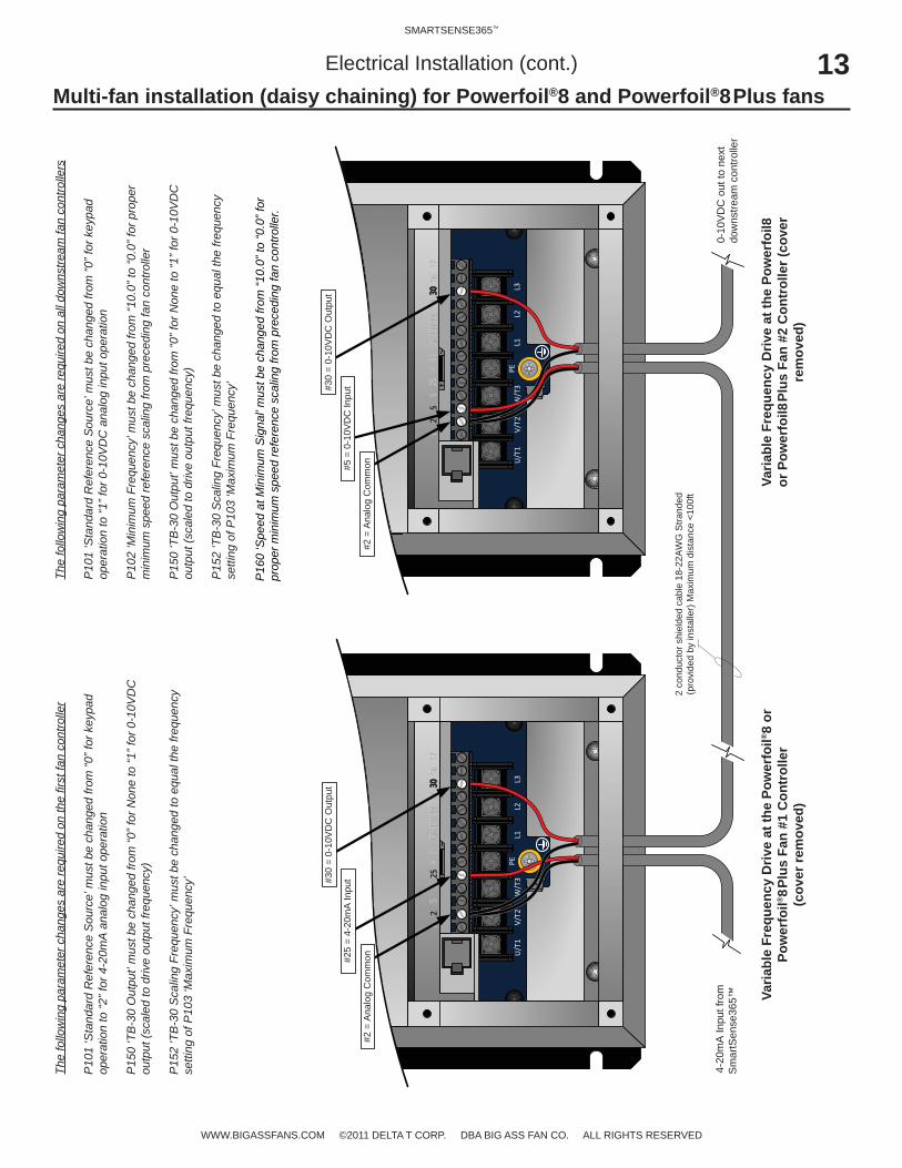
Electrical Installation (cont.)Multi-fan installation (daisy chaining) for Powerfoil®8 and Powerfoil®8Plus fans
Varia
ble
Freq
uenc
y D
rive
at th
e Po
wer
foil®
8 or
Po
wer
foil®
8Plu
s Fa
n #1
Con
trol
ler
(cov
er re
mov
ed)
Varia
ble
Freq
uenc
y D
rive
at th
e Po
wer
foil8
or
Pow
erfo
il8Pl
us F
an #
2 C
ontr
olle
r (co
ver
rem
oved
)
2 co
nduc
tor s
hiel
ded
cabl
e 18
-22A
WG
Stra
nded
(pro
vide
d by
inst
alle
r) M
axim
um d
ista
nce
<100
ft
U/T1
V/T2
W/T3
PEL1
L2L3
12
56
13A13B
13C14
3016
1725
411
12
56
13A13B
13C14
3016
1725
411
The
follo
win
g pa
ram
eter
cha
nges
are
requ
ired
on th
e fir
st fa
n co
ntro
ller
P10
1 ‘S
tand
ard
Ref
eren
ce S
ourc
e’ m
ust b
e ch
ange
d fro
m “0
” for
key
pad
oper
atio
n to
“2” f
or 4
-20m
A a
nalo
g in
put o
pera
tion
P15
0 ‘T
B-3
0 O
utpu
t’ m
ust b
e ch
ange
d fro
m “0
” for
Non
e to
“1” f
or 0
-10V
DC
ou
tput
(sca
led
to d
rive
outp
ut fr
eque
ncy)
P15
2 ‘T
B-3
0 S
calin
g Fr
eque
ncy’
mus
t be
chan
ged
to e
qual
the
frequ
ency
se
tting
of P
103
‘Max
imum
Fre
quen
cy’
4-20
mA
Inpu
t fro
m
Sm
artS
ense
365™
#2 =
Ana
log
Com
mon#2
5 =
4-20
mA
Inpu
t#30
= 0-
10V
DC
Out
put
U/T1
V/T2
W/T3
PEL1
L2L3
12
56
13A13B
13C14
3016
1725
411
12
56
13A13B
13C14
3016
1725
411
#2 =
Ana
log
Com
mon#5
= 0
-10V
DC
Inpu
t#30
= 0-
10V
DC
Out
put
0-10
VDC
out
to n
ext
dow
nstre
am c
ontro
ller
The
follo
win
g pa
ram
eter
cha
nges
are
requ
ired
on a
ll do
wns
tream
fan
cont
rolle
rs
P10
1 ‘S
tand
ard
Ref
eren
ce S
ourc
e’ m
ust b
e ch
ange
d fro
m “0
” for
key
pad
oper
atio
n to
“1” f
or 0
-10V
DC
ana
log
inpu
t ope
ratio
n
P10
2 ‘M
inim
um F
requ
ency
’ mus
t be
chan
ged
from
“10.
0” to
“0.0
” for
pro
per
min
imum
spe
ed re
fere
nce
scal
ing
from
pre
cedi
ng fa
n co
ntro
ller
P15
0 ‘T
B-3
0 O
utpu
t’ m
ust b
e ch
ange
d fro
m “0
” for
Non
e to
“1” f
or 0
-10V
DC
ou
tput
(sca
led
to d
rive
outp
ut fr
eque
ncy)
P15
2 ‘T
B-3
0 S
calin
g Fr
eque
ncy’
mus
t be
chan
ged
to e
qual
the
frequ
ency
se
tting
of P
103
‘Max
imum
Fre
quen
cy’
P16
0 ‘S
peed
at M
inim
um S
igna
l’ m
ust b
e ch
ange
d fro
m “1
0.0”
to “0
.0” f
orpr
oper
min
imum
spe
ed re
fere
nce
scal
ing
from
pre
cedi
ng fa
n co
ntro
ller.

SMARTSENSE365™
WWW.BIGASSFANS.COM ©2011 DELTA T CORP. DBA BIG ASS FAN CO. ALL RIGHTS RESERVED
Remote TemperatureSensor
Analog Common4-20mA Input
Fan ControllerAnalog Input
+24VDCDC Common
+24VDC Supply
+24V
DC
DC
Com
mon
(shi
eld)
4-20
mA
Out
put t
o Fa
nD
C C
omm
on (s
hiel
d)
RTS
Inpu
t+2
4VD
C R
TS S
uppl
y
rese
rved
DC
Com
mon
(shi
eld)
rese
rved
rese
rved
SmartSense365™Controller
+24VIN
4-20mA Out
Cable Shield Drain Leads
(if present)
Fan ControllerAnalog Input
Analog Common4-20mA Input
+24VDCDC Common
+24VDC Supply
+24V
DC
DC
Com
mon
(shi
eld)
4-20
mA
Out
put t
o Fa
nD
C C
omm
on (s
hiel
d)
RTS
Inpu
t+2
4VD
C R
TS S
uppl
y
rese
rved
DC
Com
mon
(shi
eld)
rese
rved
rese
rved
SmartSense365™Controller
+24VIN
4-20mA Out
Remote TemperatureSensor
Cable Shield Drain Leads(if present)
Temperature Sensor
Electrical Installation (cont.)
Alternative wiring methodsIf there is not a 120VAC receptacle within six (6) feet of the desired SmartSense365™ wall controller location, the installer can extend the cord of the provided power supply as needed or use one of the alternate wiring methods shown below utilizing a 3-conductor shielded cable.
15SMARTSENSE365™
WWW.BIGASSFANS.COM ©2011 DELTA T CORP. DBA BIG ASS FAN CO. ALL RIGHTS RESERVED
Operating the SmartSense365™
and the size of fan used, the minimum fan speed required to destratify can vary greatly throughout the day due to a variety of factors. In Winter Mode, the SmartSense365™ is designed to automatically adjust the fan to the optimal low speed by sampling temperature
to learn how to program your SmartSense365.
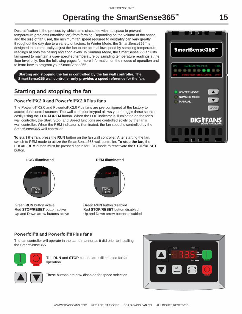
Starting and stopping the fanPowerfoil®X2.0 and Powerfoil®X2.0Plus fansThe Powerfoil®X2.0 and Powerfoil®accept dual control sources. The wall controller keypad allows you to toggle these sources easily using the LOCAL/REM button. When the LOC indicator is illuminated on the fan’s wall controller, the Start, Stop, and Speed functions are controlled solely by the fan’s wall controller. When the REM indicator is illuminated, the fan speed is controlled by the SmartSense365 wall controller.
To start the fan, press the RUN button on the fan wall controller. After starting the fan, switch to REM mode to utilize the SmartSense365 wall controller. To stop the fan, the LOCAL/REM button must be pressed again for LOC mode to reactivate the STOP/RESET button.
Green RUN button activeRed STOP/RESET button activeUp and Down arrow buttons active
Green RUN button disabledRed STOP/RESET button disabledUp and Down arrow buttons disabled
MODE
THRESHOLD TEMPERATURE
10%
55°F
100%
100°F
WINTER MODE
SUMMER MODEMANUAL
MAXIMUM FAN SPEED
LOC Illuminated REM Illuminated
Starting and stopping the fan is controlled by the fan wall controller. The SmartSense365 wall controller only provides a speed reference for the fan.
D REV REM LOC
LOCALREM
D REV REM LOC
LOCALREM
MR F
RUN
STOP
AUTO FWD
REV
Powerfoil®8 and Powerfoil®8Plus fansThe fan controller will operate in the same manner as it did prior to installing the SmartSense365.
The RUN and STOP buttons are still enabled for fan operation.
These buttons are now disabled for speed selection.
RUN STOP
16SMARTSENSE365™
WWW.BIGASSFANS.COM ©2011 DELTA T CORP. DBA BIG ASS FAN CO. ALL RIGHTS RESERVED
Operating the SmartSense365™ (cont.)
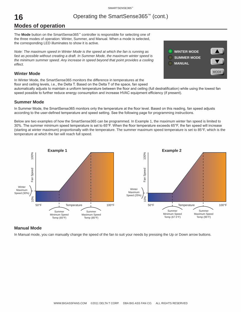
Modes of operationThe Mode button on the SmartSense365™ controller is responsible for selecting one of the three modes of operation: Winter, Summer, and Manual. When a mode is selected, the corresponding LED illuminates to show it is active.
Note: The maximum speed in Winter Mode is the speed at which the fan is running as fast as possible without creating a draft. In Summer Mode, the maximum winter speed is the minimum summer speed. Any increase in speed beyond that point provides a cooling effect.
Winter ModeIn Winter Mode, the SmartSense365 monitors the difference in temperatures at the
Summer Mode
Below are two examples of how the SmartSense365 can be programmed. In Example 1, the maximum winter fan speed is limited to
(starting at winter maximum) proportionally with the temperature. The summer maximum speed temperature is set to 85°F, which is the temperature at which the fan will reach full speed.
MODE
WINTER MODE
SUMMER MODEMANUAL
Temperature 100°F50°F
Fan
Spe
ed10
0%10
%
Winter Maximum
Speed (30%)
Summer Minimum Speed
Temp (65°F)
Summer Maximum Speed
Temp (85°F)
Temperature 100°F50°F
Fan
Spe
ed10
0%10
%
Winter Maximum
Speed (25%)
Summer Minimum Speed Temp (67.5°F)
Summer Maximum Speed
Temp (95°F)
Example 1 Example 2
Manual ModeIn Manual mode, you can manually change the speed of the fan to suit your needs by pressing the Up or Down arrow buttons.
17SMARTSENSE365™
WWW.BIGASSFANS.COM ©2011 DELTA T CORP. DBA BIG ASS FAN CO. ALL RIGHTS RESERVED
MODE
THRESHOLD TEMPERATURE
10%
55°F
100%
100°F
WINTER MODE
SUMMER MODEMANUAL
MAXIMUM FAN SPEED
Programming the SmartSense365™
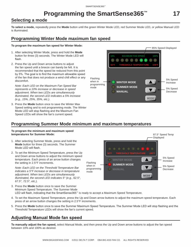
Selecting a modeTo select a mode, repeatedly press the Mode button until the green Winter Mode LED, red Summer Mode LED, or yellow Manual LED is illuminated.
Programming Winter Mode maximum fan speedTo program the maximum fan speed for Winter Mode:
1. After selecting Winter Mode, press and hold the Mode button for three (3) seconds. The Winter Mode LED will
2. Press the Up and Down arrow buttons to adjust the fan speed until a breeze can barely be felt. It is recommended that the speed be reduced from this point
of the fan that does not produce a wind chill effect or any discomfort.
Note: Each LED on the Maximum Fan Speed Bar represents a 10% increase or decrease in speed adjustment. When two LEDs are simultaneously illuminated, the second LED indicates a 5% increase (e.g., 15%, 25%, 35%, etc.).
3. Press the Mode button once to save the Winter Max Speed setting and to exit programming mode. The Winter
Speed LEDs will show the fan’s current speed.
Programming Summer Mode minimum and maximum temperaturesTo program the minimum and maximum speed temperatures for Summer Mode:
1. After selecting Summer Mode, press and hold the Mode button for three (3) seconds. The Summer
2. To set the Minimum Speed Temperature, press the Up and Down arrow buttons to adjust the minimum speed temperature. Each press of an arrow button changes the setting in 2.5°F increments.
Note: Each LED on the Threshold Temperature Bar indicates a 5°F increase or decrease in temperature adjustment. When two LEDs are simultaneously illuminated, the second LED indicates 5° (e.g., 62.5°, 67.5°, 72.5°, etc.).
3. Press the Mode button once to save the Summer Minimum Speed Temperature. The Summer Mode
™ is ready to accept a Maximum Speed Temperature.
4. To set the Maximum Speed Temperature, press the Up and Down arrow buttons to adjust the maximum speed temperature. Each press of an arrow button changes the setting in 2.5°F increments.
5. Press the ModeThreshold Temperature LEDs will show the fan’s current speed.
select Manual Mode, and then press the Up and Down arrow buttons to adjust the fan speed between 10% and 100% as desired.
MODE
WINTER MODESUMMER MODE
MANUAL
THRESHOLD TEMPERATURE50°F 100°F
Flashing when in programming mode
85% Speed Displayed
5% Speed Increase
5% Speed Decrease
Flashing when in programming mode
87.5° Speed Temp Displayed
5% Speed Increase
5% Speed Decrease
18SMARTSENSE365™
WWW.BIGASSFANS.COM ©2011 DELTA T CORP. DBA BIG ASS FAN CO. ALL RIGHTS RESERVED
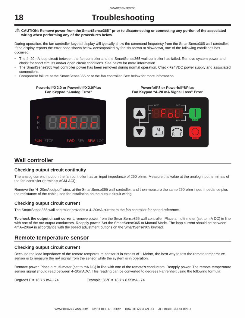
CAUTION: Remove power from the SmartSense365™ prior to disconnecting or connecting any portion of the associated wiring when performing any of the procedures below.
During operation, the fan controller keypad display will typically show the command frequency from the SmartSense365 wall controller. If the display reports the error code shown below accompanied by fan shutdown or slowdown, one of the following conditions has occurred:
The 4–20mA loop circuit between the fan controller and the SmartSense365 wall controller has failed. Remove system power and check for short circuits and/or open circuit conditions. See below for more information.The SmartSense365 wall controller power has been removed during normal operation. Check +24VDC power supply and associated connections.Component failure at the SmartSense365 or at the fan controller. See below for more information.
Wall controllerChecking output circuit continuityThe analog current input on the fan controller has an input impedance of 250 ohms. Measure this value at the analog input terminals of the fan controller (terminals ACM-ACI).
Remove the “4–20mA output” wires at the SmartSense365 wall controller, and then measure the same 250-ohm input impedance plus the resistance of the cable used for installation on the output circuit wiring.
Checking output circuit currentThe SmartSense365 wall controller provides a 4–20mA current to the fan controller for speed reference.
To check the output circuit current, remove power from the SmartSense365 wall controller. Place a multi-meter (set to mA DC) in line with one of the mA output conductors. Reapply power. Set the SmartSense365 to Manual Mode. The loop current should be between 4mA–20mA in accordance with the speed adjustment buttons on the SmartSense365 keypad.
Remote temperature sensorChecking output circuit currentBecause the load impedance of the remote temperature sensor is in excess of 1 Mohm, the best way to test the remote temperature sensor is to measure the mA signal from the sensor while the system is in operation.
Remove power. Place a multi-meter (set to mA DC) in line with one of the remote’s conductors. Reapply power. The remote temperature sensor signal should read between 4–20mADC. This reading can be converted to degrees Fahrenheit using the following formula:
Degrees F = 18.7 x mA - 74 Example: 86°F = 18.7 x 8.55mA - 74
Troubleshooting
Powerfoil®X2.0 or Powerfoil®X2.0Plus Fan Keypad “Analog Error”
Powerfoil®8 or Powerfoil®8Plus
RUN STOP FWD REV REM LOC
UHF
MR F
RUN
STOP
AUTO FWD
REV


1001240101*1001240101*
REV E