smart@unsw sustainability internationalsmart.unsw.edu.au/sites/default/files/presentations-session...
TRANSCRIPT

Innovative Waste Recycling and Energy Efficiency Solutions
Session 4 : Early Career Professionals Session
Dr Pedro Yunes
2013
Inter
natio
nal S
ustai
nabil
ity S
ympo
sium
SMaRT@
UNSW

“Overview of the waste recycling process
in the Zinc smelter at Nyrstar Port Pirie”
Presented by
Dr. Pedro Yunes
Nyrstar Port Pirie
Mobile: (+61) 0419164703
2013
Inter
natio
nal S
ustai
nabil
ity S
ympo
sium
SMaRT@
UNSW
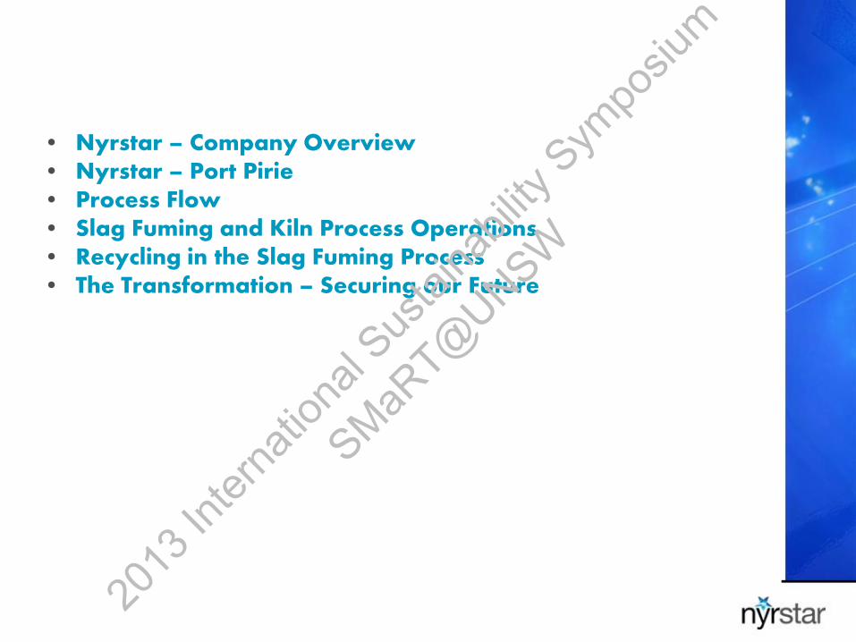
• Nyrstar – Company Overview • Nyrstar – Port Pirie • Process Flow • Slag Fuming and Kiln Process Operations • Recycling in the Slag Fuming Process • The Transformation – Securing our Future
2013
Inter
natio
nal S
ustai
nabil
ity S
ympo
sium
SMaRT@
UNSW
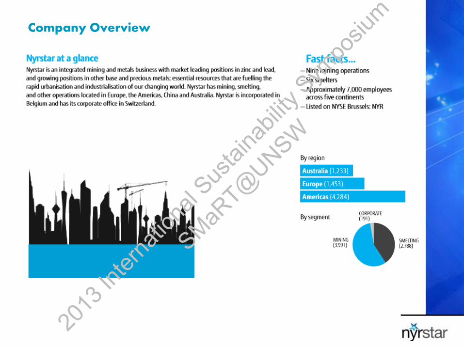
Company Overview
2013
Inter
natio
nal S
ustai
nabil
ity S
ympo
sium
SMaRT@
UNSW
2013
Inter
natio
nal S
ustai
nabil
ity S
ympo
sium
SMaRT@
UNSW

Nyrstar Port Pirie
2013
Inter
natio
nal S
ustai
nabil
ity S
ympo
sium
SMaRT@
UNSW

Nyrstar Port Pirie – Process Flow
6
CSB/SHED
Acid Plant
KDR
Clean Gas
Copper Leach
Residue
Rich Slag Mix Concentrates
Blended Cons
Sinter Feed
Raw Fume
Coke Sinter
Return Hot
Slag Spent
Slag
Coal
MIXING PLANT
CASTING SRF CADMIUM PLANT
(r)
(r)
(r)
KILN
BAGHOUSE Centrifuge(s)
COPPER PLANT
Rich Gas
Lean Gas
Fume Slurry
Refined Silver 9997 Lead Crude Gold
PM Fume
Copper
Ca Alloy
Caustic Dross
Crude Sb Alloy
Market Zinc
Cathode Zinc
Roast Fume
Zinc
Scum
Zinc
dross
CDF Slag
9999 Lead
CTB
Zinc
PCC Bullion
Bullion
Softener Slag
Effluent KDR U/F
5003 Sb Alloy
Tall Stack
LG Lead
(r)
SRF
INCIRCULATION
REFINERY
ALLOY PLANT
RESIDUE
LEAD ALLOYS
KILNS
SLAG FUMER
LEACH/ELECT
KBA
PRECIOUS METALS
MIXING PLANT
SINTER PLANT
BLAST FURNACE
CDF
Liquation
Copper Matte
VIR Zinc
HG Alloy
Sb Alloy
Zinc Leach residue (r)
ESP
CASTING
Granulated
Slag Ladle
Skull
Boiler
Ash
2013
Inter
natio
nal S
ustai
nabil
ity S
ympo
sium
SMaRT@
UNSW
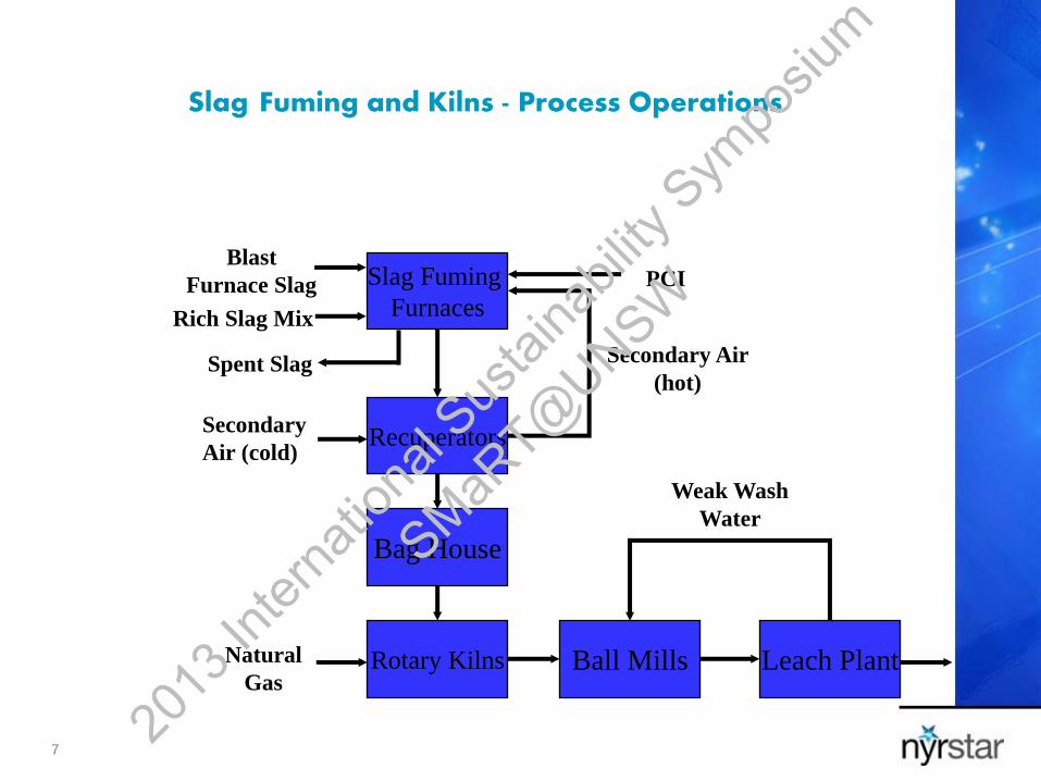
Slag Fuming and Kilns - Process Operations
7
Slag Fuming
Furnaces Rich Slag Mix
Blast
Furnace Slag
Recuperators
Bag House
Rotary Kilns Ball Mills
PCI
Secondary Air
(hot)
Natural
Gas
Weak Wash
Water
Leach Plant
Secondary
Air (cold)
Spent Slag
2013
Inter
natio
nal S
ustai
nabil
ity S
ympo
sium
SMaRT@
UNSW

Slag Fuming and Kilns Process Operations
8
WESTERN SIDE OF THE SLAG
FUMING PLANT
ROTARY KILN #2
2013
Inter
natio
nal S
ustai
nabil
ity S
ympo
sium
SMaRT@
UNSW
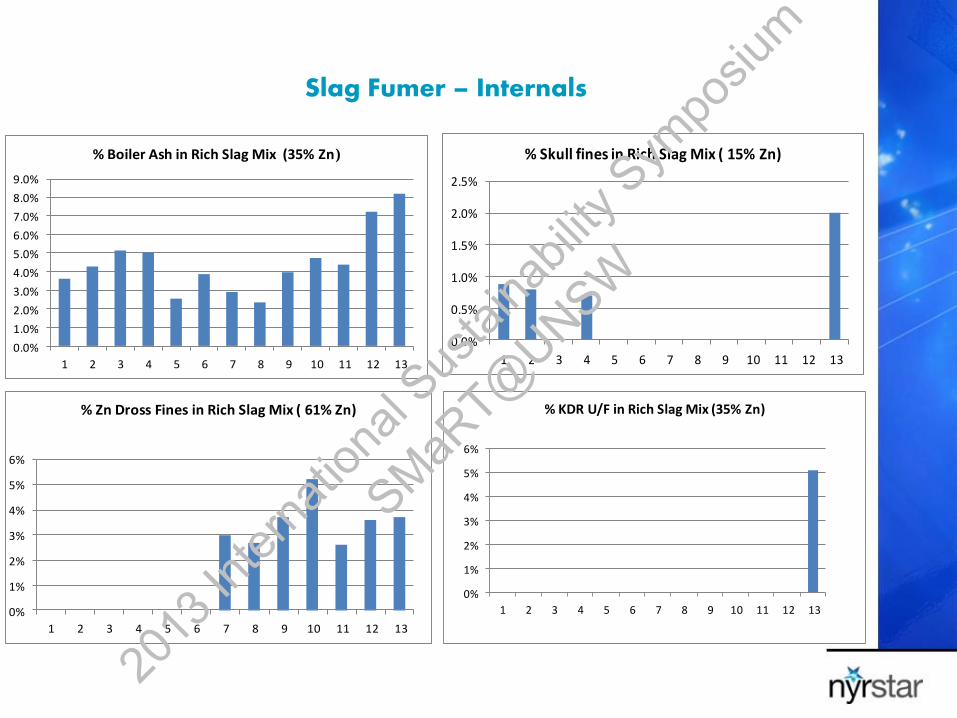
Slag Fumer – Internals
0.0%
1.0%
2.0%
3.0%
4.0%
5.0%
6.0%
7.0%
8.0%
9.0%
1 2 3 4 5 6 7 8 9 10 11 12 13
% Boiler Ash in Rich Slag Mix (35% Zn)
0.0%
0.5%
1.0%
1.5%
2.0%
2.5%
1 2 3 4 5 6 7 8 9 10 11 12 13
% Skull fines in Rich Slag Mix ( 15% Zn)
0%
1%
2%
3%
4%
5%
6%
1 2 3 4 5 6 7 8 9 10 11 12 13
% Zn Dross Fines in Rich Slag Mix ( 61% Zn)
0%
1%
2%
3%
4%
5%
6%
1 2 3 4 5 6 7 8 9 10 11 12 13
% KDR U/F in Rich Slag Mix (35% Zn)
2013
Inter
natio
nal S
ustai
nabil
ity S
ympo
sium
SMaRT@
UNSW
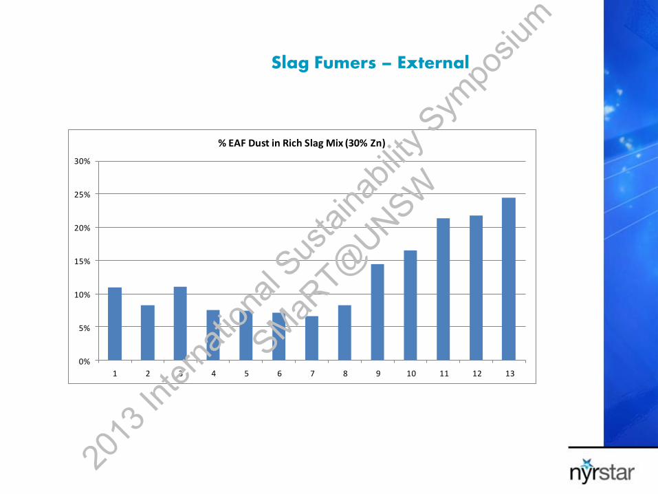
Slag Fumers – External
0%
5%
10%
15%
20%
25%
30%
1 2 3 4 5 6 7 8 9 10 11 12 13
% EAF Dust in Rich Slag Mix (30% Zn)
2013
Inter
natio
nal S
ustai
nabil
ity S
ympo
sium
SMaRT@
UNSW

From being primarily a lead smelter….
The Transformation – Today
Schematic of the sinter plant that will be phased out
2013
Inter
natio
nal S
ustai
nabil
ity S
ympo
sium
SMaRT@
UNSW
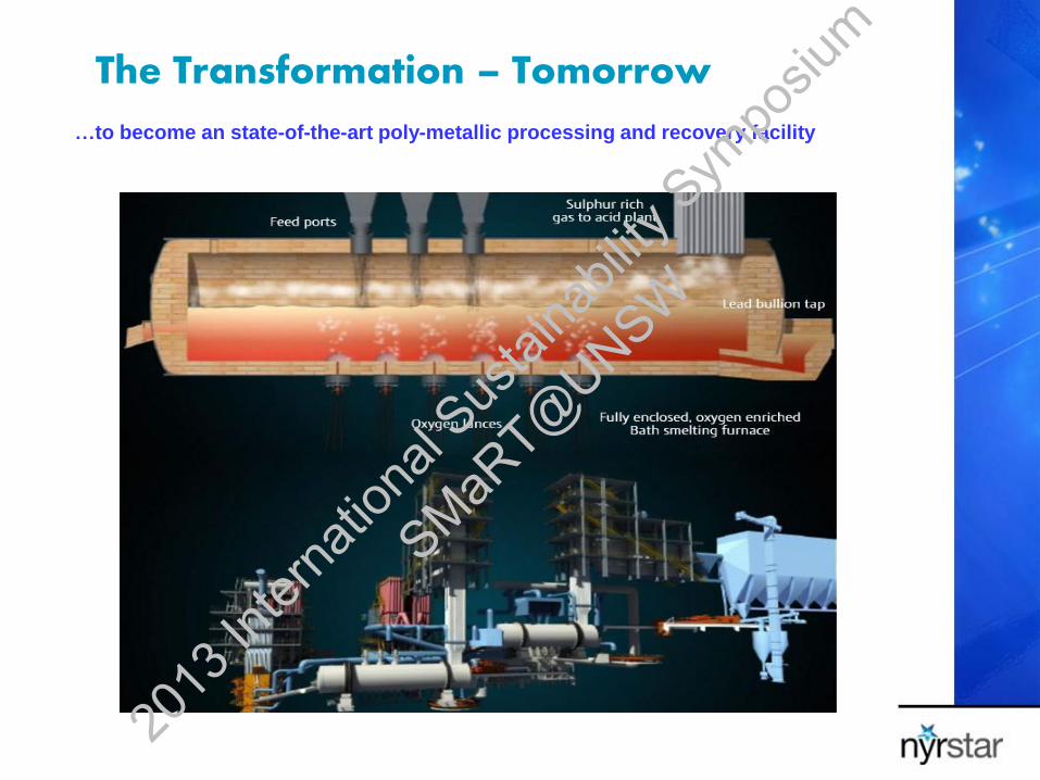
The Transformation – Tomorrow
…to become an state-of-the-art poly-metallic processing and recovery facility
2013
Inter
natio
nal S
ustai
nabil
ity S
ympo
sium
SMaRT@
UNSW
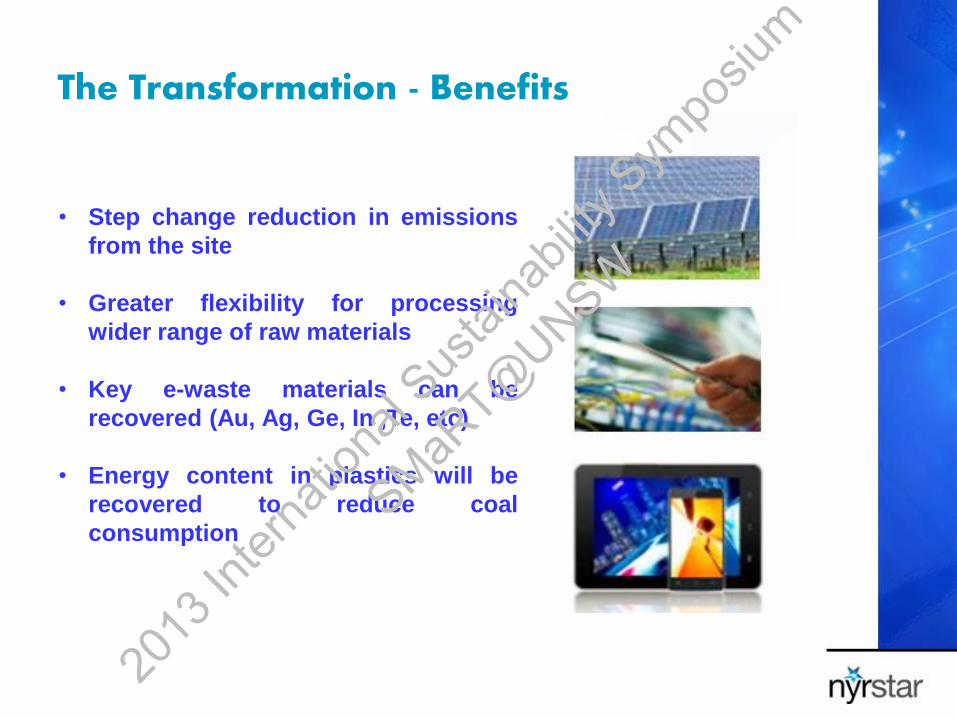
The Transformation - Benefits
• Step change reduction in emissions
from the site
• Greater flexibility for processing
wider range of raw materials
• Key e-waste materials can be
recovered (Au, Ag, Ge, In ,Te, etc)
• Energy content in plastics will be
recovered to reduce coal
consumption
2013
Inter
natio
nal S
ustai
nabil
ity S
ympo
sium
SMaRT@
UNSW
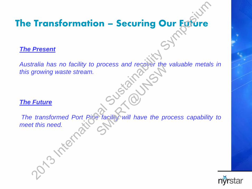
The Transformation – Securing Our Future
The Present
Australia has no facility to process and recover the valuable metals in
this growing waste stream.
The Future
The transformed Port Pirie facility will have the process capability to
meet this need.
2013
Inter
natio
nal S
ustai
nabil
ity S
ympo
sium
SMaRT@
UNSW
Questions ??
Thanks for your attention
2013
Inter
natio
nal S
ustai
nabil
ity S
ympo
sium
SMaRT@
UNSW

Innovative Waste Recycling and Energy Efficiency Solutions
Session 4 : Early Career Professionals Session
Lisa Green
2013
Inter
natio
nal S
ustai
nabil
ity S
ympo
sium
SMaRT@
UNSW
Working with Industry to
Achieve Compliance Lisa Green
Intelligence Unit
Department of Environment and Heritage
Protection
2013
Inter
natio
nal S
ustai
nabil
ity S
ympo
sium
SMaRT@
UNSW
Background to EHP
Mission:
Strong environmental regulator which supports sustainable long-
term economic development in Queensland
Enabled by:
– Building relationships with government, business, industry and
the community
– Innovative, evidence-based environmental policies, programs
and services
2013
Inter
natio
nal S
ustai
nabil
ity S
ympo
sium
SMaRT@
UNSW
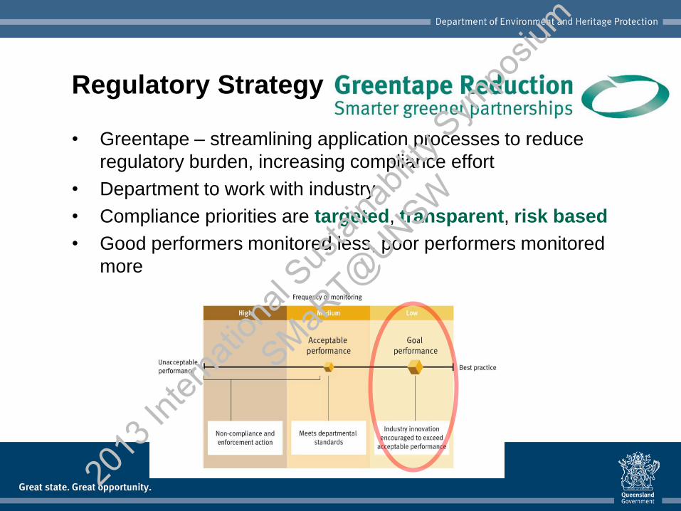
• Greentape – streamlining application processes to reduce
regulatory burden, increasing compliance effort
• Department to work with industry
• Compliance priorities are targeted, transparent, risk based
• Good performers monitored less, poor performers monitored
more
Regulatory Strategy
2013
Inter
natio
nal S
ustai
nabil
ity S
ympo
sium
SMaRT@
UNSW
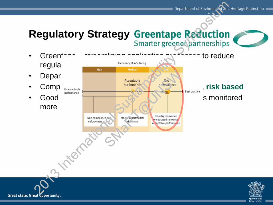
• Greentape – streamlining application processes to reduce
regulatory burden, increasing compliance effort
• Department to work with industry
• Compliance priorities are targeted, transparent, risk based
• Good performers monitored less, poor performers monitored
more
Regulatory Strategy
2013
Inter
natio
nal S
ustai
nabil
ity S
ympo
sium
SMaRT@
UNSW
Waste Industry
• Much of Queensland’s waste is sent straight to landfill –
valuable resources are being lost
• Waste levy was repealed following 2012 Queensland State
Elections
• Challenge – encourage innovation and investment in the
state’s recycled waste industry without a levy
• Queensland is currently reviewing its waste strategy through
an ‘industry-led’ process
2013
Inter
natio
nal S
ustai
nabil
ity S
ympo
sium
SMaRT@
UNSW

Compliance
• Department has increased compliance effort
• Compliance focus is risk-based, targeted and transparent
• Compliance is not intended to inhibit industry’s drive for
innovation
• It is to: understand where key risks exist, why they exist
and develop effective and appropriate strategies to
target these risks
• The department will take prompt, strong enforcement action
to those who intentionally choose not to comply
2013
Inter
natio
nal S
ustai
nabil
ity S
ympo
sium
SMaRT@
UNSW
Intelligence-Led Compliance
• Purpose:
Collate and analyse information to understand risk to inform
policy development and compliance planning
• This function:
– monitors and identifies risk
– establishes causes of non-compliance
– identifies instances of unlicensed activity
– monitors and informs management and officers of new
technologies and processes
2013
Inter
natio
nal S
ustai
nabil
ity S
ympo
sium
SMaRT@
UNSW
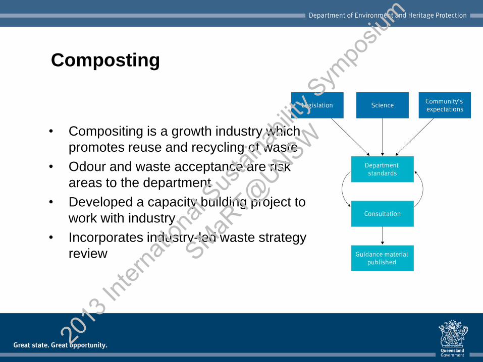
Composting
• Compositing is a growth industry which
promotes reuse and recycling of waste
• Odour and waste acceptance are risk
areas to the department
• Developed a capacity building project to
work with industry
• Incorporates industry-led waste strategy
review
2013
Inter
natio
nal S
ustai
nabil
ity S
ympo
sium
SMaRT@
UNSW
Unlined Landfills
• Leachate is a key risk of unlined landfills
• Intelligence Unit is analysing data from a variety of sources to
identify high risk unlined landfill sites
• The department will work with site operators and incorporate
new technologies to improve monitoring
2013
Inter
natio
nal S
ustai
nabil
ity S
ympo
sium
SMaRT@
UNSW
Sustainable development is a collaboration between regulators,
industry and the community
The department will increase its monitoring to ensure compliance
Business and industry are best-placed to work out how to stay
compliant
EHP will work collaboratively with industry and the community to
develop standards, polices to manage and protect environment and
heritage yet assist investment in the state’s recycled waste industry
Summary
2013
Inter
natio
nal S
ustai
nabil
ity S
ympo
sium
SMaRT@
UNSW

Innovative Waste Recycling and Energy Efficiency Solutions
Session 4 : Early Career Professionals Session
Dr Nawshad Haque
2013
Inter
natio
nal S
ustai
nabil
ity S
ympo
sium
SMaRT@
UNSW
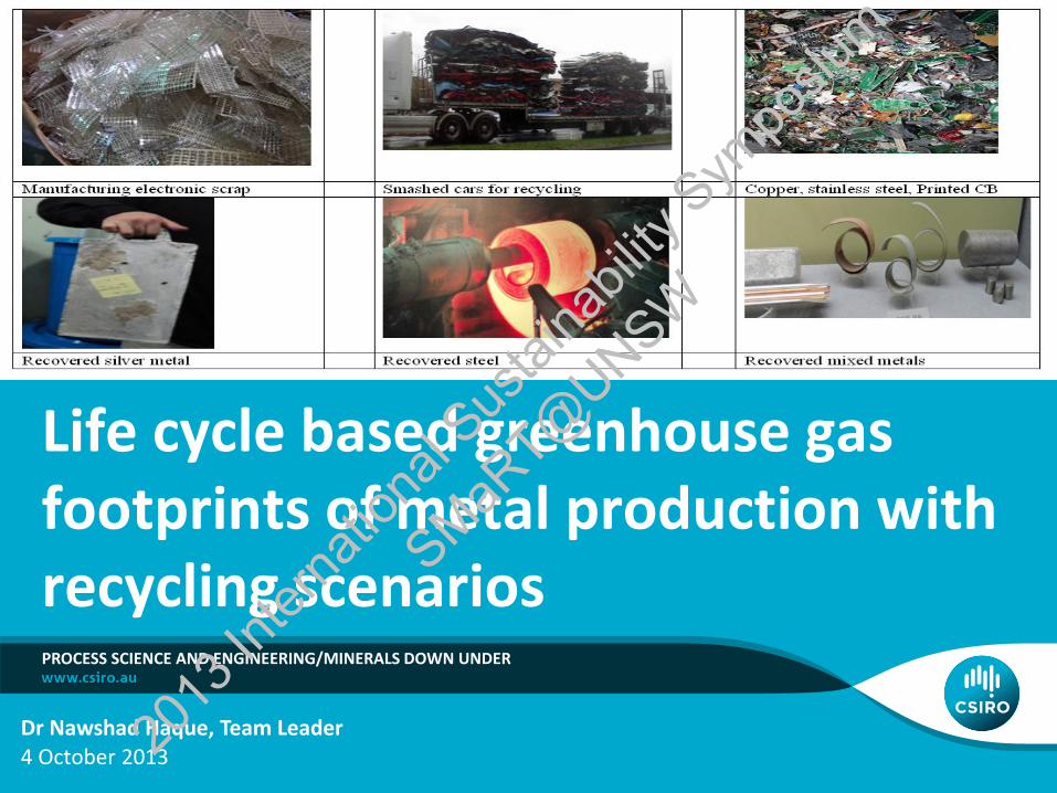
Life cycle based greenhouse gas footprints of metal production with recycling scenarios
Dr Nawshad Haque, Team Leader 4 October 2013
PROCESS SCIENCE AND ENGINEERING/MINERALS DOWN UNDER
2013
Inter
natio
nal S
ustai
nabil
ity S
ympo
sium
SMaRT@
UNSW
Outline
• Introduction to LCA •LCA of mining and metals •Material recovery facility •Boundary and assessment •Key results for steel and aluminium •Concluding remarks
Life cycle assessment | Nawshad Haque 2 | 20
13 In
terna
tiona
l Sus
taina
bility
Sym
posiu
m
SMaRT@
UNSW
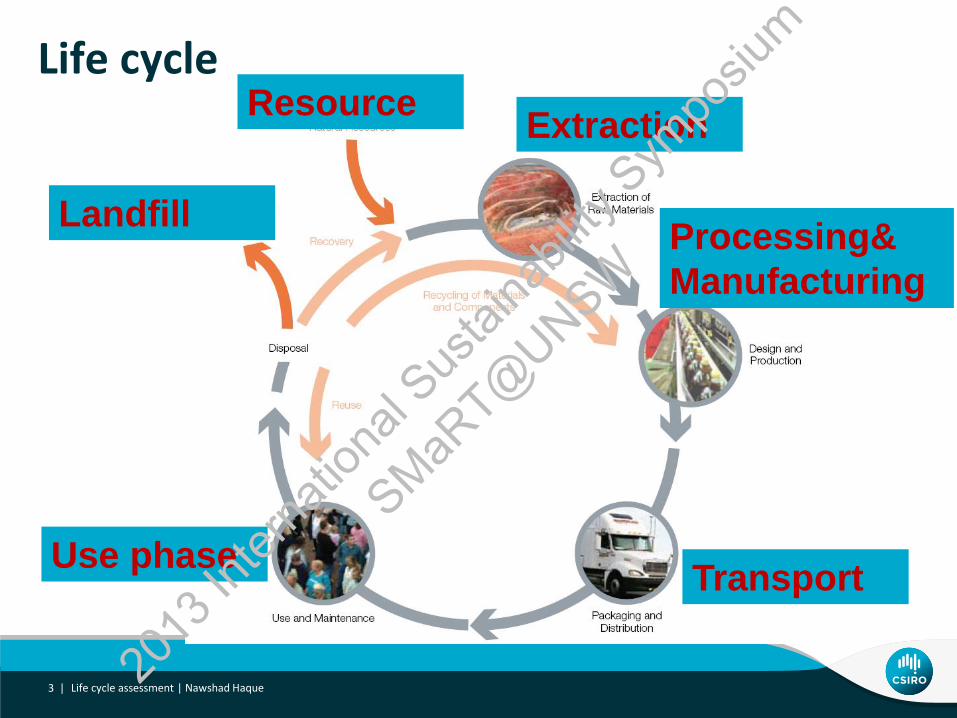
Life cycle
Extraction
Processing&
Manufacturing
Transport Use phase
Resource
Landfill
3 | Life cycle assessment | Nawshad Haque 20
13 In
terna
tiona
l Sus
taina
bility
Sym
posiu
m
SMaRT@
UNSW

Stages of LCA
• Why and for whom?
• Boundary demarcation, data collection
• Impact category selection, characterisation
• Assessment, interpretation, sensitivity analysis
• Update & improvement with new data
Goal and
scope
definition
Inventory
analysis
Impact
Assessment
Interpretation
4 | Life cycle assessment | Nawshad Haque 20
13 In
terna
tiona
l Sus
taina
bility
Sym
posiu
m
SMaRT@
UNSW
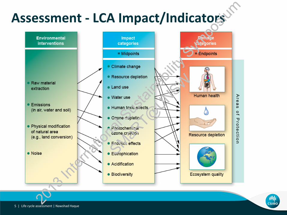
Assessment - LCA Impact/Indicators
5 | Life cycle assessment | Nawshad Haque 20
13 In
terna
tiona
l Sus
taina
bility
Sym
posiu
m
SMaRT@
UNSW

Example flowsheet
6 | Life cycle assessment | Nawshad Haque 20
13 In
terna
tiona
l Sus
taina
bility
Sym
posiu
m
SMaRT@
UNSW

Metals – “Cradle-to-Gate” – GWP
0
5
10
15
20
25
Ste
el
S/S
teel
Alum
inium
Cop
per
Cop
per
Lead
Lead
Nicke
l
Nicke
l
Zinc
Zinc
t C
O2 e
/t o
f m
eta
l
Norgate et al . (2007) J of Cleaner Production, 15:838-848.
Pyro
Hydro
o
BF
ISF
Pyro
Hydro
Electrolytic
ISF
7 | Life cycle assessment | Nawshad Haque 20
13 In
terna
tiona
l Sus
taina
bility
Sym
posiu
m
SMaRT@
UNSW

LCA works of CSIRO in Mining & Metals
8 | Life cycle assessment | Nawshad Haque 20
13 In
terna
tiona
l Sus
taina
bility
Sym
posiu
m
SMaRT@
UNSW
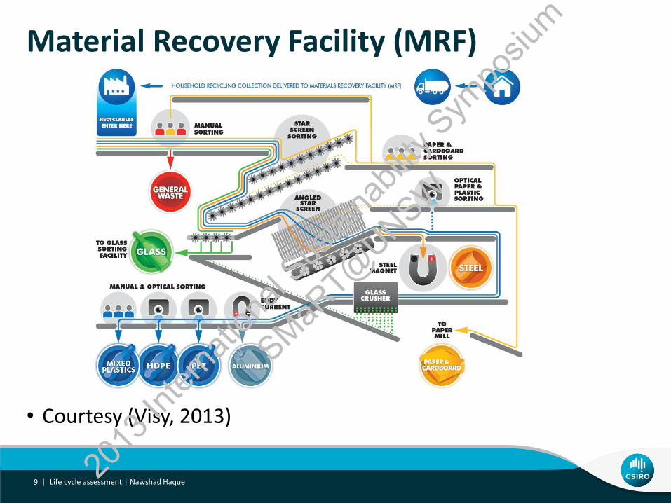
Material Recovery Facility (MRF)
• Courtesy (Visy, 2013)
Life cycle assessment | Nawshad Haque 9 | 20
13 In
terna
tiona
l Sus
taina
bility
Sym
posiu
m
SMaRT@
UNSW

Material Recovery Facility (MRF)
Life cycle assessment | Nawshad Haque 10 | 20
13 In
terna
tiona
l Sus
taina
bility
Sym
posiu
m
SMaRT@
UNSW
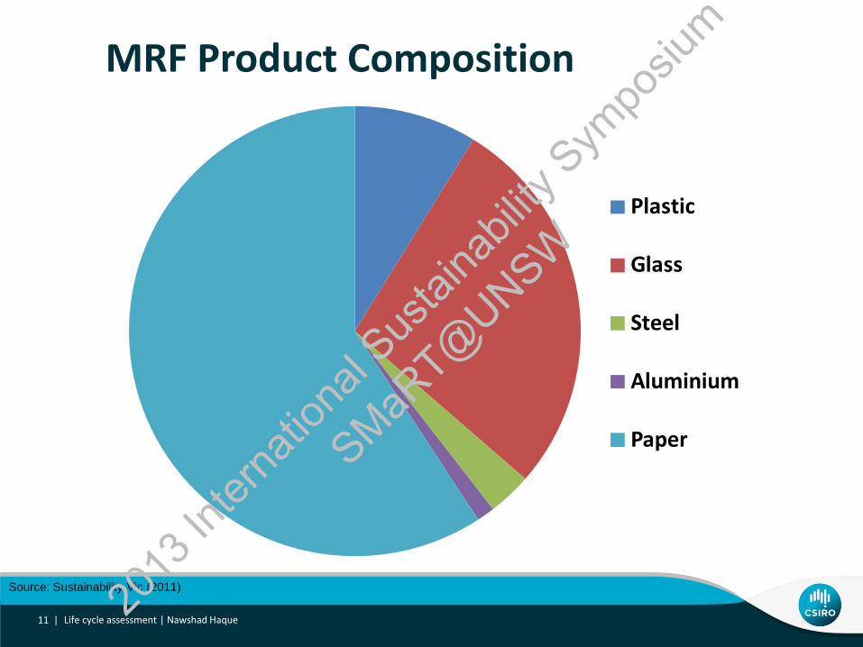
MRF Product Composition
Life cycle assessment | Nawshad Haque 11 |
Plastic
Glass
Steel
Aluminium
Paper
Source: Sustainability Vic (2011) 2013
Inter
natio
nal S
ustai
nabil
ity S
ympo
sium
SMaRT@
UNSW
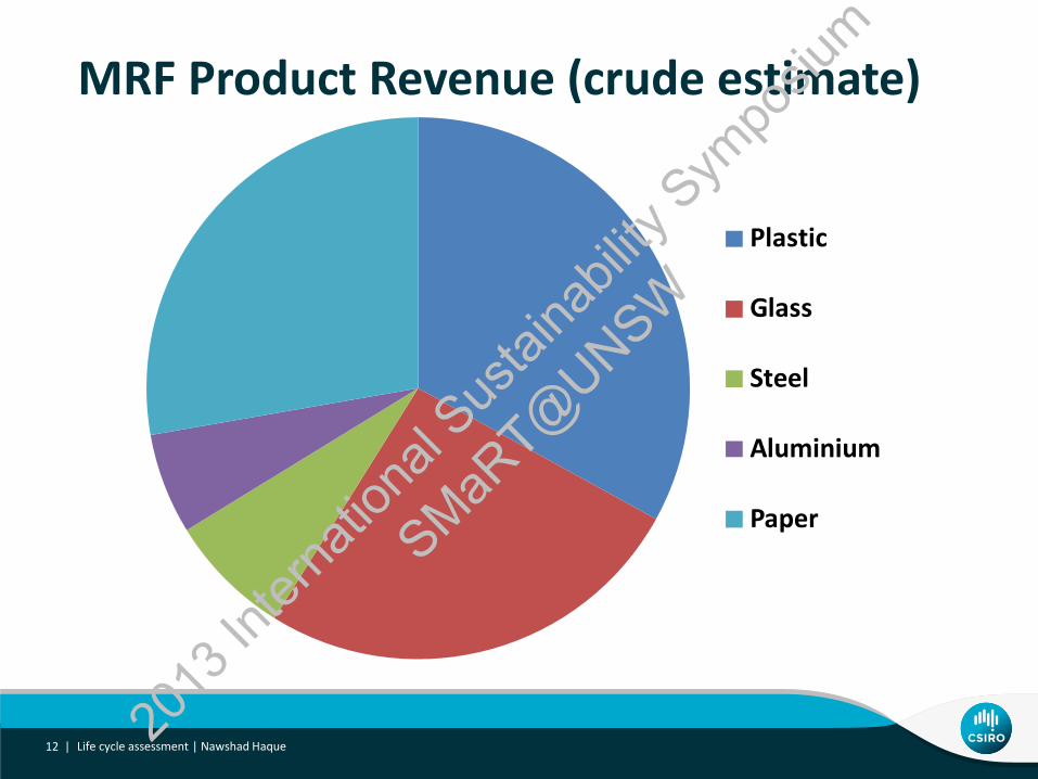
MRF Product Revenue (crude estimate)
Life cycle assessment | Nawshad Haque 12 |
Plastic
Glass
Steel
Aluminium
Paper
2013
Inter
natio
nal S
ustai
nabil
ity S
ympo
sium
SMaRT@
UNSW
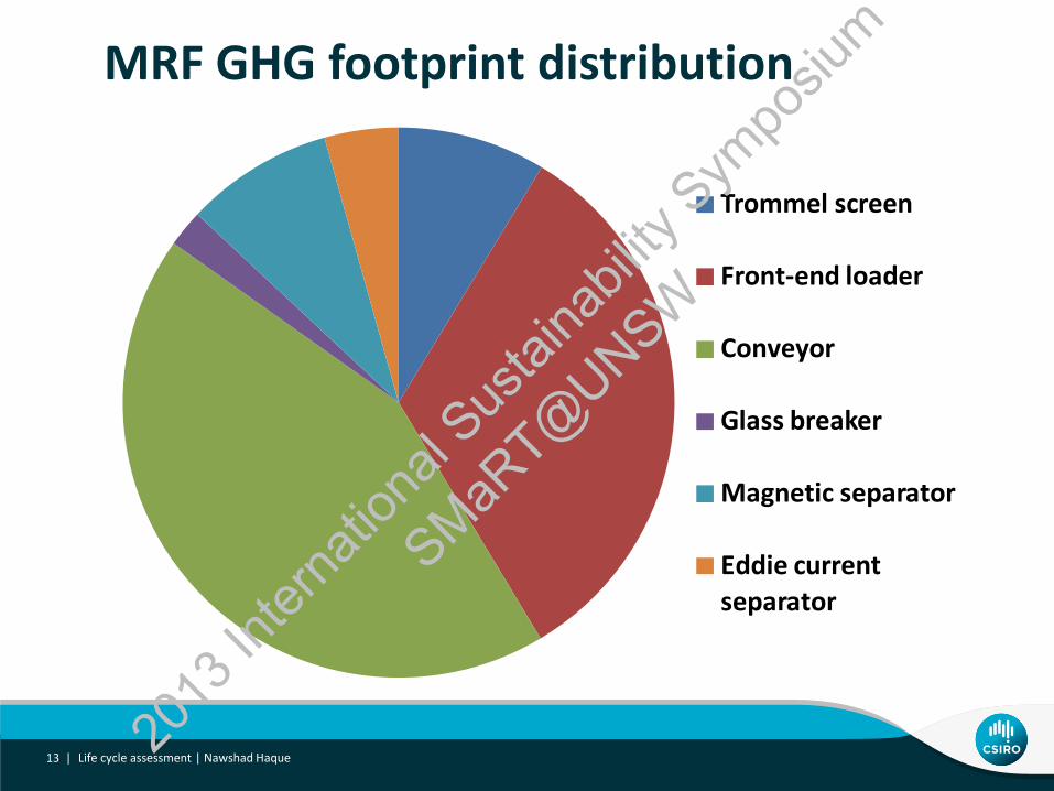
MRF GHG footprint distribution
Life cycle assessment | Nawshad Haque 13 |
Trommel screen
Front-end loader
Conveyor
Glass breaker
Magnetic separator
Eddie current
separator
2013
Inter
natio
nal S
ustai
nabil
ity S
ympo
sium
SMaRT@
UNSW

GHG footprint of recycled steel if sent overseas for reprocessing
Life cycle assessment | Nawshad Haque 14 | 20
13 In
terna
tiona
l Sus
taina
bility
Sym
posiu
m
SMaRT@
UNSW

GHG footprint of recycled aluminium if sent overseas for reprocessing
Life cycle assessment | Nawshad Haque 15 | 20
13 In
terna
tiona
l Sus
taina
bility
Sym
posiu
m
SMaRT@
UNSW
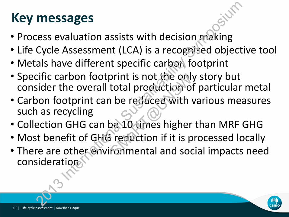
Key messages • Process evaluation assists with decision making • Life Cycle Assessment (LCA) is a recognised objective tool • Metals have different specific carbon footprint • Specific carbon footprint is not the only story but
consider the overall total production of particular metal • Carbon footprint can be reduced with various measures
such as recycling • Collection GHG can be 10 times higher than MRF GHG • Most benefit of GHG reduction if it is processed locally • There are other environmental and social impacts need
consideration
16 | Life cycle assessment | Nawshad Haque 20
13 In
terna
tiona
l Sus
taina
bility
Sym
posiu
m
SMaRT@
UNSW
International activities and engagements • Australia-India Workshop on LCA for mining, mineral processing metal making
industries
• Dates: 20 & 21 January 2014
• Will be supported by Indian School of Mines University and Australia India Council division of DFAT
• Working under CSIRO-KIGAM Korea collaboration on rare earth and recycling
• Bangladesh CSIR and CSIRO Collaboration on metals and mineral sands processing
• Hosted Ministerial delegation visit, developed list of action items about process evaluation and other studies
• Mineral samples analysed, recommendations made
• Secondment of a BCSIR staff and a joint workshop planned in January 2014
17 | Life cycle assessment | Nawshad Haque 20
13 In
terna
tiona
l Sus
taina
bility
Sym
posiu
m
SMaRT@
UNSW
• For assistance & supports: • CSIRO Colleagues (T. Norgate, Dr. S. Jahanshahi, Dr. J. Rankin, A Monch, S
Northey, A Littleboy, M Cooksey)
• An unnamed City Council
• For more information:
• Explore website csiro.au
Acknowledgements
18 | Life cycle assessment | Nawshad Haque 20
13 In
terna
tiona
l Sus
taina
bility
Sym
posiu
m
SMaRT@
UNSW
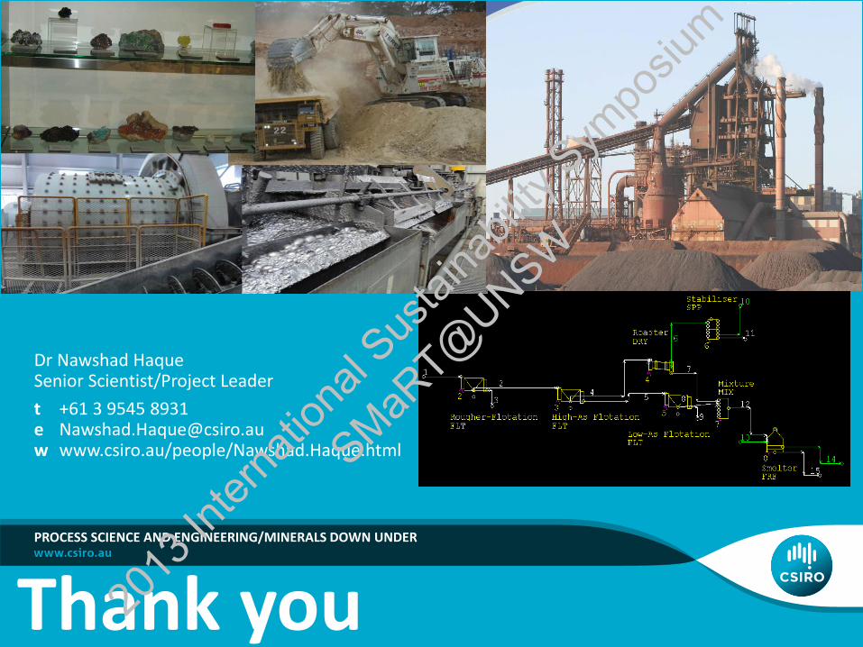
PROCESS SCIENCE AND ENGINEERING/MINERALS DOWN UNDER
Thank you
Dr Nawshad Haque Senior Scientist/Project Leader
t +61 3 9545 8931 e [email protected] w www.csiro.au/people/Nawshad.Haque.html
2013
Inter
natio
nal S
ustai
nabil
ity S
ympo
sium
SMaRT@
UNSW

Innovative Waste Recycling and Energy Efficiency Solutions
Session 4 : Early Career Professionals Session
Manudha Herath
2013
Inter
natio
nal S
ustai
nabil
ity S
ympo
sium
SMaRT@
UNSW

Structural Optimisation Using Bend-Twist
Coupling For Wind Turbine Blades
School of Mechanical and Manufacturing Engineering
Prepared By: Mr Aaron Lee
Supervisor: A/Prof. B. Gangadhara Prusty
Co-Supervisor and Presenter:
Mr Manudha (Thinu) Herath
2013 INTERNATIONAL SUSTAINABILITY SYMPOSIUM
Innovative Waste Recycling and Energy Efficiency Solutions
2013
Inter
natio
nal S
ustai
nabil
ity S
ympo
sium
SMaRT@
UNSW
Structural Optimisation Using Bend-Twist Coupling
For Wind Turbine Blades
Presentation overview
Background
Introduction of shape-adaptive blades
Past research findings
Our approach - Preliminary design framework
Differential Stiffness Bend-Twist (DSBT) Coupling
Composite material layup optimisation
Summary and future work
2013
Inter
natio
nal S
ustai
nabil
ity S
ympo
sium
SMaRT@
UNSW
Structural Optimisation Using Bend-Twist Coupling
For Wind Turbine Blades
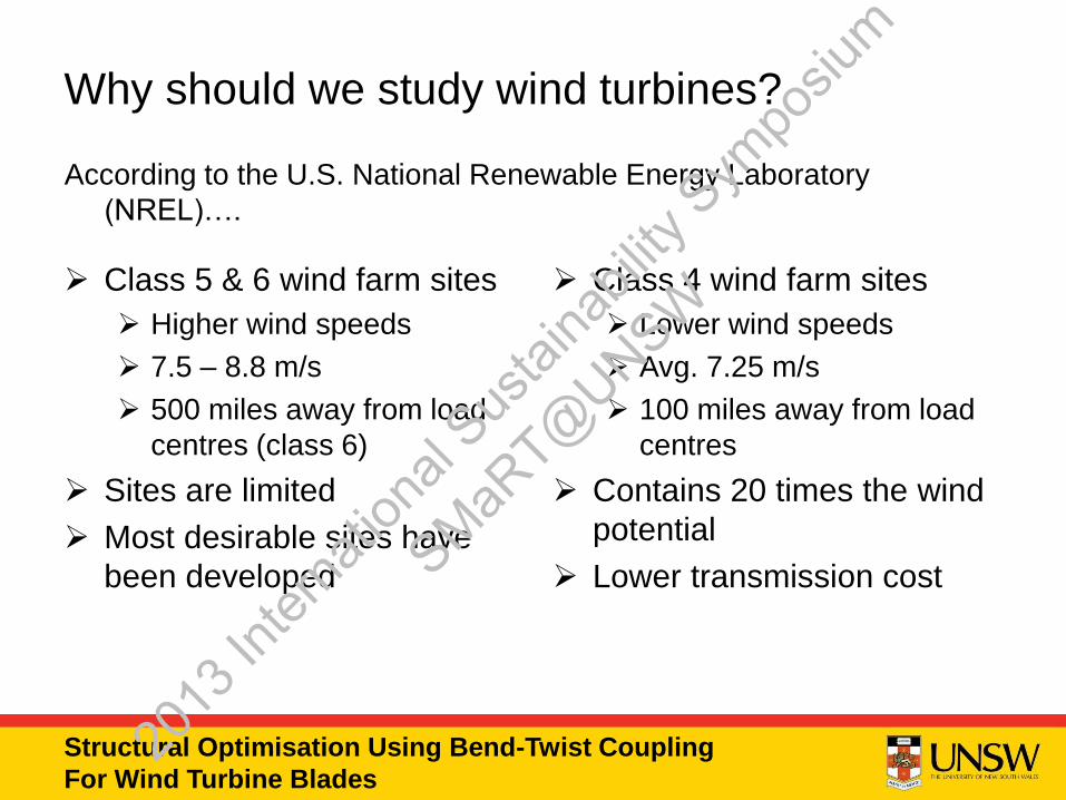
According to the U.S. National Renewable Energy Laboratory
(NREL)….
Class 5 & 6 wind farm sites
Higher wind speeds
7.5 – 8.8 m/s
500 miles away from load
centres (class 6)
Sites are limited
Most desirable sites have
been developed
Class 4 wind farm sites
Lower wind speeds
Avg. 7.25 m/s
100 miles away from load
centres
Contains 20 times the wind
potential
Lower transmission cost
Why should we study wind turbines?
2013
Inter
natio
nal S
ustai
nabil
ity S
ympo
sium
SMaRT@
UNSW
Structural Optimisation Using Bend-Twist Coupling
For Wind Turbine Blades
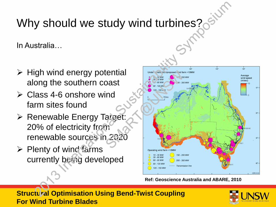
In Australia…
High wind energy potential
along the southern coast
Class 4-6 onshore wind
farm sites found
Renewable Energy Target:
20% of electricity from
renewable sources in 2020
Plenty of wind farms
currently being developed
Why should we study wind turbines?
Ref: Geoscience Australia and ABARE, 2010
2013
Inter
natio
nal S
ustai
nabil
ity S
ympo
sium
SMaRT@
UNSW
Structural Optimisation Using Bend-Twist Coupling
For Wind Turbine Blades
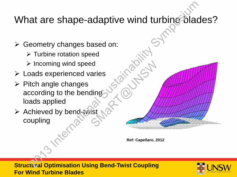
Geometry changes based on:
Turbine rotation speed
Incoming wind speed
Loads experienced varies
Pitch angle changes
according to the bending
loads applied
Achieved by bend-twist
coupling
What are shape-adaptive wind turbine blades?
Ref: Capellaro, 2012
2013
Inter
natio
nal S
ustai
nabil
ity S
ympo
sium
SMaRT@
UNSW

Structural Optimisation Using Bend-Twist Coupling
For Wind Turbine Blades
One of the passive pitch
control methods
Bending introduces
torsional deformation
Usually achieved by using
the anisotropic properties of
composites
What is bend-twist coupling?
Ref: Jones, 1999
2013
Inter
natio
nal S
ustai
nabil
ity S
ympo
sium
SMaRT@
UNSW
Structural Optimisation Using Bend-Twist Coupling
For Wind Turbine Blades
Why do we need shape-adaptive blades?
For bend-twist coupled blades that twist towards feather:
Bending load increases as wind speed increases
Induced twist lowers the pitch angle
Lower aerodynamic loads experienced
Reduced fatigue damage
Lower maintenance cost
Extended service life
Weaker, lighter structures can be use
Larger blades can then be designed
More energy can be captured
Design improvements promote the development of low-wind
speed sites
2013
Inter
natio
nal S
ustai
nabil
ity S
ympo
sium
SMaRT@
UNSW

Structural Optimisation Using Bend-Twist Coupling
For Wind Turbine Blades
Instability observed for coupled blades twisting towards stall
Lower fatigue loads for coupled blades twisting towards
feather
Past research findings
Coupled, towards feather
Coupled, towards stall
Uncoupled, baseline
Ref: Adapted from Lobitz and Laino, 1998
2013
Inter
natio
nal S
ustai
nabil
ity S
ympo
sium
SMaRT@
UNSW
Structural Optimisation Using Bend-Twist Coupling
For Wind Turbine Blades
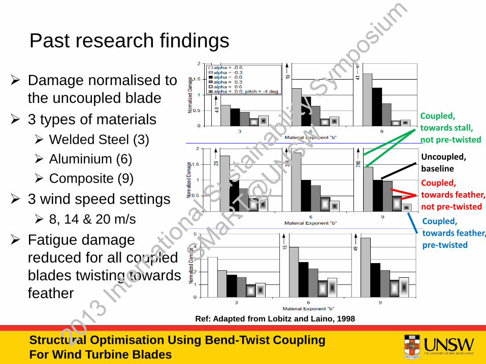
Damage normalised to
the uncoupled blade
3 types of materials
Welded Steel (3)
Aluminium (6)
Composite (9)
3 wind speed settings
8, 14 & 20 m/s
Fatigue damage
reduced for all coupled
blades twisting towards
feather
Past research findings
Uncoupled,
baseline
Coupled,
towards feather,
not pre-twisted
Coupled,
towards feather,
pre-twisted
Coupled,
towards stall,
not pre-twisted
Ref: Adapted from Lobitz and Laino, 1998
2013
Inter
natio
nal S
ustai
nabil
ity S
ympo
sium
SMaRT@
UNSW
Structural Optimisation Using Bend-Twist Coupling
For Wind Turbine Blades
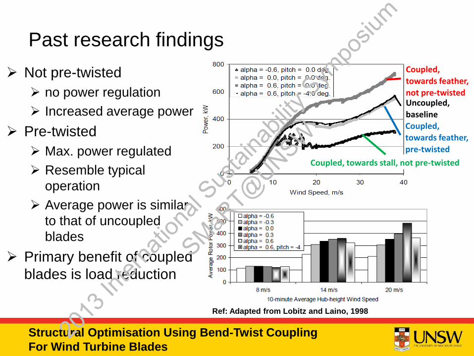
Not pre-twisted
no power regulation
Increased average power
Pre-twisted
Max. power regulated
Resemble typical
operation
Average power is similar
to that of uncoupled
blades
Primary benefit of coupled
blades is load reduction
Past research findings
Uncoupled,
baseline
Coupled,
towards feather,
pre-twisted
Coupled, towards stall, not pre-twisted
Coupled,
towards feather,
not pre-twisted
Ref: Adapted from Lobitz and Laino, 1998
2013
Inter
natio
nal S
ustai
nabil
ity S
ympo
sium
SMaRT@
UNSW

Structural Optimisation Using Bend-Twist Coupling
For Wind Turbine Blades
Conventional design
approach
Fibres placed at an angle
to the flexural axis to create
biased laminates
Biased laminates applied
either at the skin panels or
the spar caps
Strain incompatibilities
found
Upper and lower skin joint
Spar cap/web connection
Past research findings
Ref: de Goeij et al., 1999
2013
Inter
natio
nal S
ustai
nabil
ity S
ympo
sium
SMaRT@
UNSW
Structural Optimisation Using Bend-Twist Coupling
For Wind Turbine Blades
Our approach - DSBT coupling
Definition of Differential Stiffness Bend-Twist (DSBT) coupling:
“to control the bend-twist coupling of the global structure by
incorporating structural sub-components with distinctly
different stiffness values that would experience bending as
their main deformation”
Avoids the design of bend-twist coupled sub-components
Minimise/eliminate strain incompatibilities at joints
2013
Inter
natio
nal S
ustai
nabil
ity S
ympo
sium
SMaRT@
UNSW
Structural Optimisation Using Bend-Twist Coupling
For Wind Turbine Blades
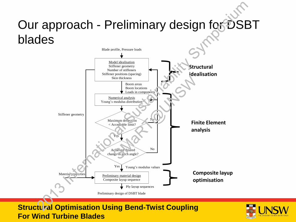
Our approach - Preliminary design for DSBT
blades
Model idealisation
Stiffener geometry
Number of stiffeners
Stiffener positions (spacing)
Skin thickness
Boom areas
Boom locations
Loads in components
Numerical analysis
Young’s modulus distribution
No
No
Yes
Preliminary material design
Composite layup sequence
Ply layup sequences
Material properties
Preliminary design of DSBT blade
Yes
Blade profile, Pressure loads
Stiffener geometry
Young’s modulus values
Maximum deflection
< Acceptable limit?
Achieved desired
change in pitch angle?
Finite Element
analysis
Structural
idealisation
Composite layup
optimisation
2013
Inter
natio
nal S
ustai
nabil
ity S
ympo
sium
SMaRT@
UNSW
Structural Optimisation Using Bend-Twist Coupling
For Wind Turbine Blades
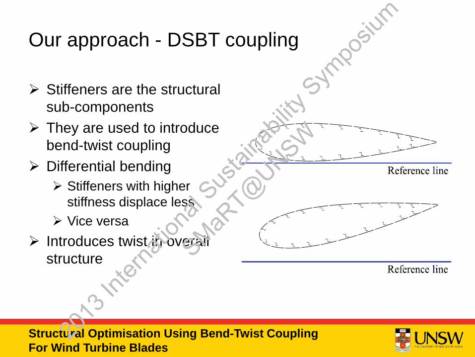
Stiffeners are the structural
sub-components
They are used to introduce
bend-twist coupling
Differential bending
Stiffeners with higher
stiffness displace less
Vice versa
Introduces twist in overall
structure
Our approach - DSBT coupling
2013
Inter
natio
nal S
ustai
nabil
ity S
ympo
sium
SMaRT@
UNSW
Structural Optimisation Using Bend-Twist Coupling
For Wind Turbine Blades
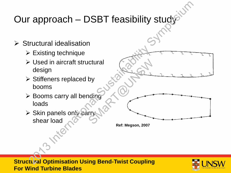
Structural idealisation
Existing technique
Used in aircraft structural
design
Stiffeners replaced by
booms
Booms carry all bending
loads
Skin panels only carry
shear load
Our approach – DSBT feasibility study
Ref: Megson, 2007
2013
Inter
natio
nal S
ustai
nabil
ity S
ympo
sium
SMaRT@
UNSW
Structural Optimisation Using Bend-Twist Coupling
For Wind Turbine Blades
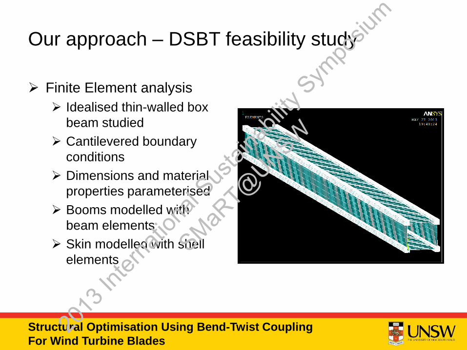
Finite Element analysis
Idealised thin-walled box
beam studied
Cantilevered boundary
conditions
Dimensions and material
properties parameterised
Booms modelled with
beam elements
Skin modelled with shell
elements
Our approach – DSBT feasibility study
2013
Inter
natio
nal S
ustai
nabil
ity S
ympo
sium
SMaRT@
UNSW
Structural Optimisation Using Bend-Twist Coupling
For Wind Turbine Blades
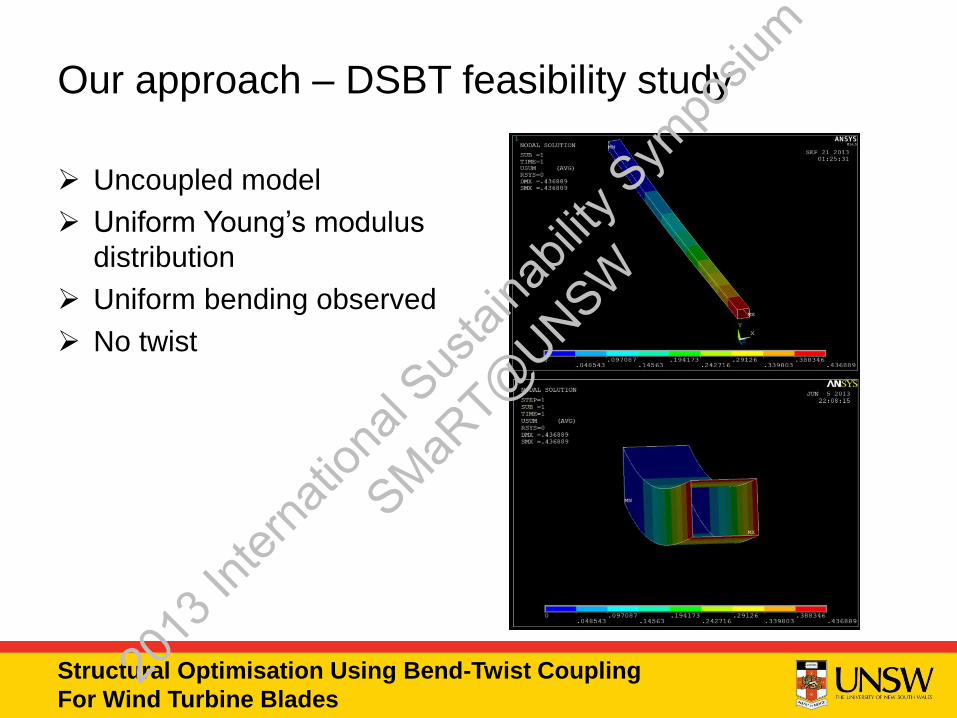
Uncoupled model
Uniform Young’s modulus
distribution
Uniform bending observed
No twist
Our approach – DSBT feasibility study
2013
Inter
natio
nal S
ustai
nabil
ity S
ympo
sium
SMaRT@
UNSW
Structural Optimisation Using Bend-Twist Coupling
For Wind Turbine Blades
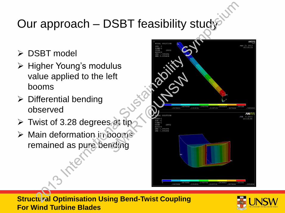
DSBT model
Higher Young’s modulus
value applied to the left
booms
Differential bending
observed
Twist of 3.28 degrees at tip
Main deformation in booms
remained as pure bending
Our approach – DSBT feasibility study
2013
Inter
natio
nal S
ustai
nabil
ity S
ympo
sium
SMaRT@
UNSW
Structural Optimisation Using Bend-Twist Coupling
For Wind Turbine Blades
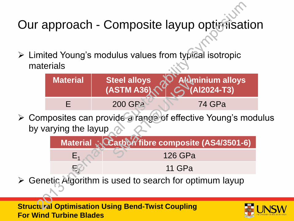
Our approach - Composite layup optimisation
Limited Young’s modulus values from typical isotropic
materials
Composites can provide a range of effective Young’s modulus
by varying the layup
Genetic Algorithm is used to search for optimum layup
Material Steel alloys
(ASTM A36)
Aluminium alloys
(Al2024-T3)
E 200 GPa 74 GPa
Material Carbon fibre composite (AS4/3501-6)
E1 126 GPa
E2 11 GPa
2013
Inter
natio
nal S
ustai
nabil
ity S
ympo
sium
SMaRT@
UNSW
Structural Optimisation Using Bend-Twist Coupling
For Wind Turbine Blades
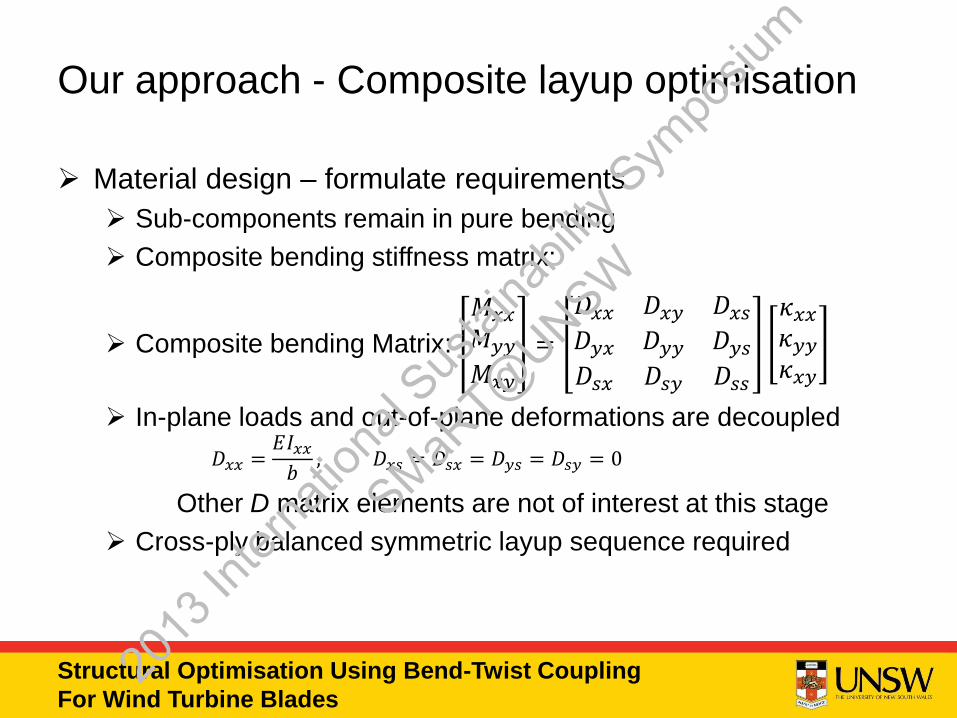
Our approach - Composite layup optimisation
Material design – formulate requirements
Sub-components remain in pure bending
Composite bending stiffness matrix:
Composite bending Matrix:
𝑀𝑥𝑥
𝑀𝑦𝑦
𝑀𝑥𝑦
=
𝐷𝑥𝑥 𝐷𝑥𝑦 𝐷𝑥𝑠
𝐷𝑦𝑥 𝐷𝑦𝑦 𝐷𝑦𝑠
𝐷𝑠𝑥 𝐷𝑠𝑦 𝐷𝑠𝑠
𝜅𝑥𝑥
𝜅𝑦𝑦
𝜅𝑥𝑦
In-plane loads and out-of-plane deformations are decoupled
𝐷𝑥𝑥 =𝐸𝐼𝑥𝑥
𝑏, 𝐷𝑥𝑠 = 𝐷𝑠𝑥 = 𝐷𝑦𝑠 = 𝐷𝑠𝑦 = 0
Other D matrix elements are not of interest at this stage
Cross-ply balanced symmetric layup sequence required
2013
Inter
natio
nal S
ustai
nabil
ity S
ympo
sium
SMaRT@
UNSW

Structural Optimisation Using Bend-Twist Coupling
For Wind Turbine Blades
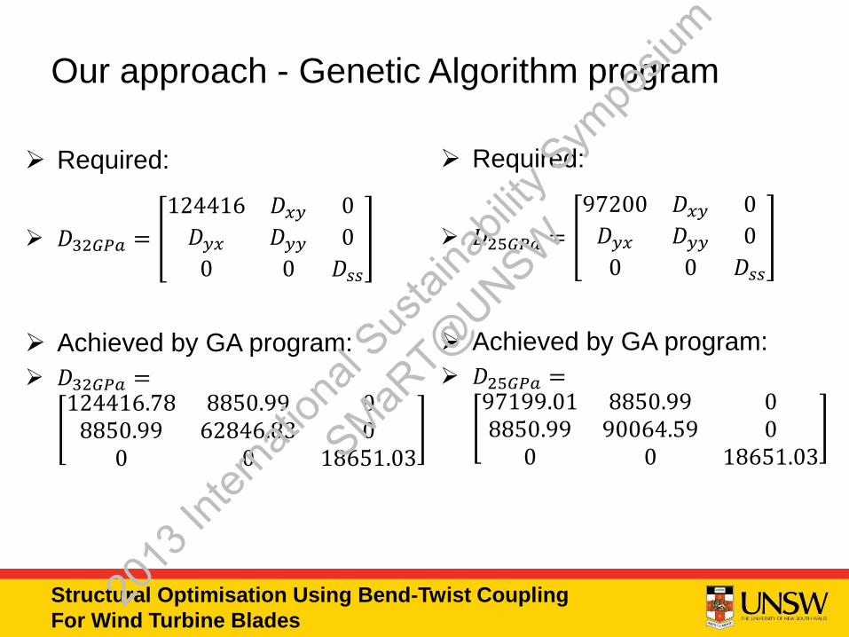
Our approach – Genetic Algorithm program
In-house Genetic Algorithm (GA) program used for
optimisation
Input variables: Fibre orientation angle of each ply
Target: Required D matrix values
𝑓 𝜽𝑚𝑖𝑛
= 𝐷𝑥𝑥𝑟𝑒𝑞 − 𝐷𝑥𝑥𝐺𝐴
GA optimisation procedure
1st generation randomly formulated
Evaluate error
Formulate next generation through natural selection, cross-over
of parent generation and mutation
Iterate until satisfactory results are obtained
2013
Inter
natio
nal S
ustai
nabil
ity S
ympo
sium
SMaRT@
UNSW
Structural Optimisation Using Bend-Twist Coupling
For Wind Turbine Blades
Required:
𝐷32𝐺𝑃𝑎 =
124416 𝐷𝑥𝑦 0
𝐷𝑦𝑥 𝐷𝑦𝑦 0
0 0 𝐷𝑠𝑠
Achieved by GA program:
𝐷32𝐺𝑃𝑎 =124416.78 8850.99 0
8850.99 62846.83 00 0 18651.03
Required:
𝐷25𝐺𝑃𝑎 =
97200 𝐷𝑥𝑦 0
𝐷𝑦𝑥 𝐷𝑦𝑦 0
0 0 𝐷𝑠𝑠
Achieved by GA program:
𝐷25𝐺𝑃𝑎 =97199.01 8850.99 08850.99 90064.59 0
0 0 18651.03
Our approach - Genetic Algorithm program
2013
Inter
natio
nal S
ustai
nabil
ity S
ympo
sium
SMaRT@
UNSW
Structural Optimisation Using Bend-Twist Coupling
For Wind Turbine Blades
Summary
Preliminary design procedure
Structural idealisation
Finite element analysis to predict twist
Genetic algorithm for layup optimisation
DSBT is a feasible concept
Achieved by applying non-uniform Young’s modulus distribution
in sub-components
Composite layup can be optimised
Provides the required Young’s modulus value
2013
Inter
natio
nal S
ustai
nabil
ity S
ympo
sium
SMaRT@
UNSW
Structural Optimisation Using Bend-Twist Coupling
For Wind Turbine Blades
Future work – where to now?
Experimental verification of the DSBT concept
Improve the design procedure by:
Adapt the procedure for complex non-symmetrical structures
Integrate the FE analysis and the GA program
Consider different load cases
Incorporate failure theories
2013
Inter
natio
nal S
ustai
nabil
ity S
ympo
sium
SMaRT@
UNSW
Structural Optimisation Using Bend-Twist Coupling
For Wind Turbine Blades
References
CAPELLARO, M. 2012. Design Challenges for Bend Twist Coupled Blades for Wind Turbines: and
application to standard blades. 2012 Sandia Wind Turbine Blade Workshop. Albuquerque, New
Mexico: University of Stuttgart.
DE GOEIJ, W. C., VAN TOOREN, M. J. L. & BEUKERS, A. 1999. Implementation of bending-torsion
coupling in the design of a wind-turbine rotor-blade. Applied Energy, 63, 191-207.
GEOSCIENCE AUSTRALIA & ABARE 2010. Australian Energy Resource Assessment.
JONES, R. M. 1999. Mechanics of composite materials, CRC Press.
LOBITZ, D. W. & LAINO, D. J. 1998. Load Mitigation with Twist-coupled HAWT Blades. ASME Wind
Energy Symposium. Reno, Nevada.
MEGSON, T. H. G. 2007. Aircraft structures for engineering students, Elsevier/Butterworth-
Heinemann.
2013
Inter
natio
nal S
ustai
nabil
ity S
ympo
sium
SMaRT@
UNSW
Structural Optimisation Using Bend-Twist Coupling
For Wind Turbine Blades
Questions??
Thank you
2013
Inter
natio
nal S
ustai
nabil
ity S
ympo
sium
SMaRT@
UNSW
Innovative Waste Recycling and Energy Efficiency Solutions
Session 4 : Early Career Professionals Session
Hewitt Park
2013
Inter
natio
nal S
ustai
nabil
ity S
ympo
sium
SMaRT@
UNSW
The influence of CaO-FexOy-Al2O3-SiO2 oxide system
on the reduction of carbon composite pellet
04/10/2013
Hewitt Park* and Veena Sahajwalla
Centre for Sustainable Materials Research & Technology (SMaRT@UNSW)
2013
Inter
natio
nal S
ustai
nabil
ity S
ympo
sium
SMaRT@
UNSW
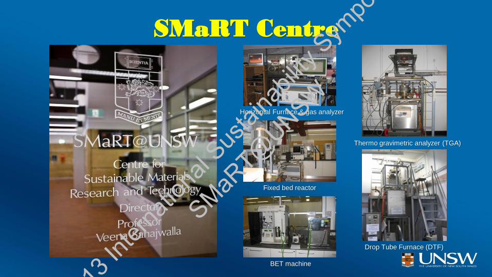
SMaRT Centre
Thermo gravimetric analyzer (TGA)
Drop Tube Furnace (DTF)
Horizontal Furnace & gas analyzer
Fixed bed reactor
BET machine
2013
Inter
natio
nal S
ustai
nabil
ity S
ympo
sium
SMaRT@
UNSW
SMaRT Centre
July 5th, 2013
2013
Inter
natio
nal S
ustai
nabil
ity S
ympo
sium
SMaRT@
UNSW
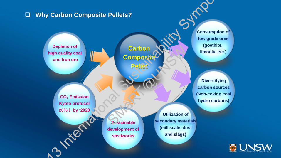
Why Carbon Composite Pellets?
Carbon
Composite
Pellet
Utilization of
secondary materials
(mill scale, dust
and slags)
Diversifying
carbon sources
(Non-coking coal,
hydro carbons)
Depletion of
high quality coal
and Iron ore
Consumption of
low grade ores
(goethite,
limonite etc.)
CO2 Emission
Kyoto protocol
20%↓ by ‘2020
Sustainable
development of
steelworks
2013
Inter
natio
nal S
ustai
nabil
ity S
ympo
sium
SMaRT@
UNSW
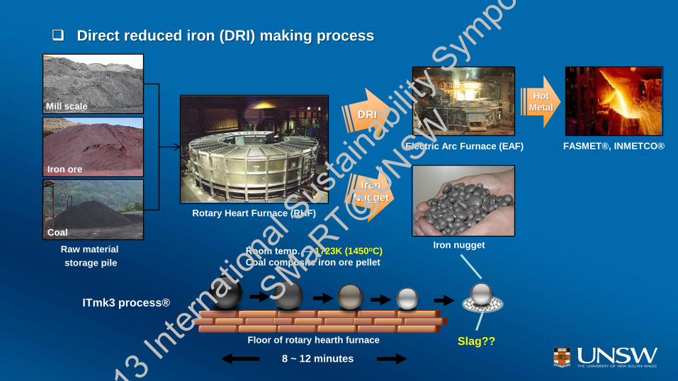
Floor of rotary hearth furnace
Room temp. → 1723K (1450oC)
Coal composite iron ore pellet
Iron nugget
Slag??
8 ~ 12 minutes
Rotary Heart Furnace (RHF)
ITmk3 process®
FASMET®, INMETCO®
Raw material
storage pile
Coal
Iron ore
Mill scale
Electric Arc Furnace (EAF)
Iron
Nugget
Hot
Metal
Direct reduced iron (DRI) making process
DRI
2013
Inter
natio
nal S
ustai
nabil
ity S
ympo
sium
SMaRT@
UNSW
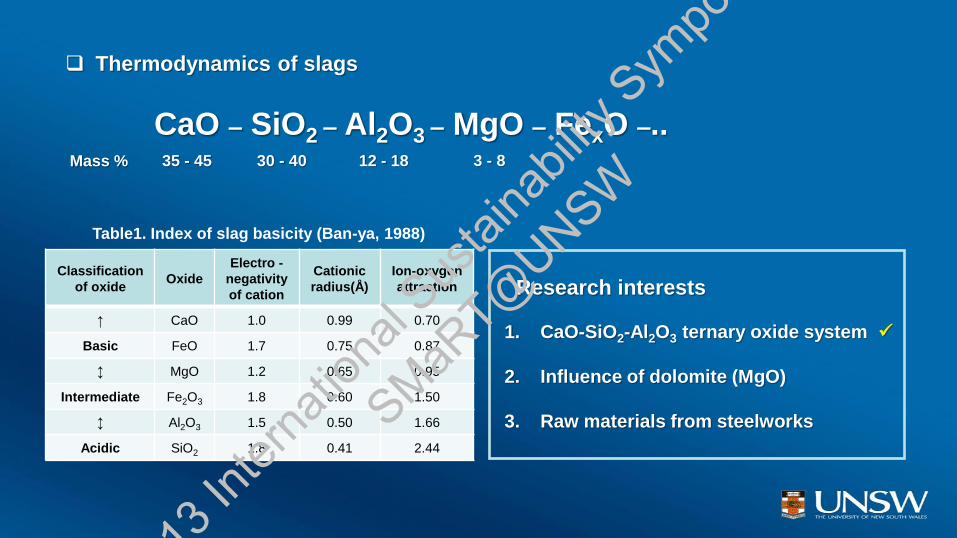
CaO – SiO2 – Al2O3 – MgO – FexO –..
Thermodynamics of slags
1. CaO-SiO2-Al2O3 ternary oxide system
2. Influence of dolomite (MgO)
3. Raw materials from steelworks
Classification
of oxide Oxide
Electro -
negativity
of cation
Cationic
radius(Å)
Ion-oxygen
attraction
↑ CaO 1.0 0.99 0.70
Basic FeO 1.7 0.75 0.87
↕ MgO 1.2 0.65 0.95
Intermediate Fe2O3 1.8 0.60 1.50
↕ Al2O3 1.5 0.50 1.66
Acidic SiO2 1.8 0.41 2.44
Table1. Index of slag basicity (Ban-ya, 1988)
Research interests
35 - 45 12 - 18 3 - 8 30 - 40 Mass %
2013
Inter
natio
nal S
ustai
nabil
ity S
ympo
sium
SMaRT@
UNSW
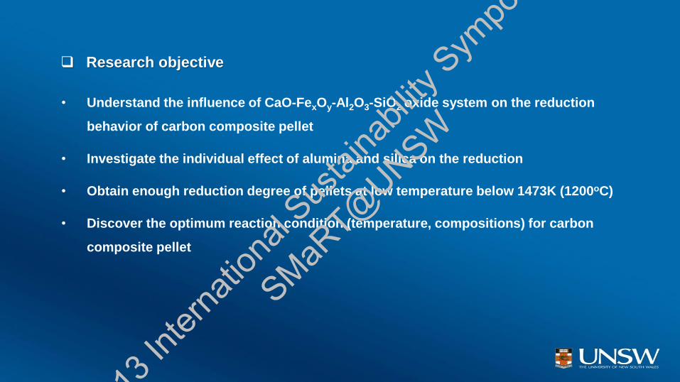
Research objective
• Understand the influence of CaO-FexOy-Al2O3-SiO2 oxide system on the reduction
behavior of carbon composite pellet
• Investigate the individual effect of alumina and silica on the reduction
• Obtain enough reduction degree of pellets at low temperature below 1473K (1200oC)
• Discover the optimum reaction condition (temperature, compositions) for carbon
composite pellet
2013
Inter
natio
nal S
ustai
nabil
ity S
ympo
sium
SMaRT@
UNSW
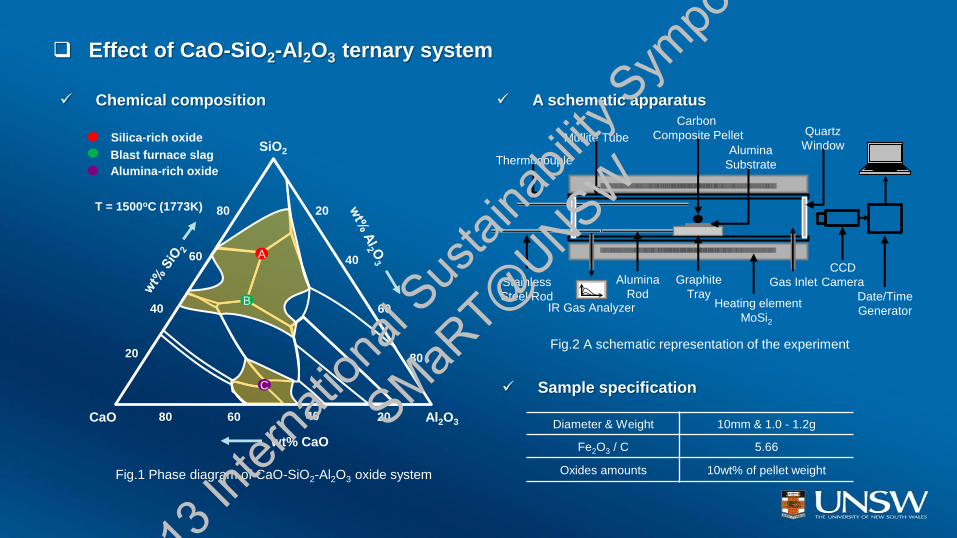
Chemical composition
Fig.2 A schematic representation of the experiment
Thermocouple
Stainless
Steel Rod
Gas Inlet Alumina
Rod
Graphite
Tray
Alumina
Substrate
Carbon
Composite Pellet Mullite Tube Quartz
Window
Heating element
MoSi2
CCD
Camera
Date/Time
Generator IR Gas Analyzer
Effect of CaO-SiO2-Al2O3 ternary system
T = 1500oC (1773K)
Silica-rich oxide
Blast furnace slag
Alumina-rich oxide
wt% CaO
20
40
60
80
80 60 20
20
40
SiO2
CaO 40
80
60
Al2O3
A
B
C
Fig.1 Phase diagram of CaO-SiO2-Al2O3 oxide system
A schematic apparatus
Sample specification
Diameter & Weight 10mm & 1.0 - 1.2g
Fe2O3 / C 5.66
Oxides amounts 10wt% of pellet weight
2013
Inter
natio
nal S
ustai
nabil
ity S
ympo
sium
SMaRT@
UNSW
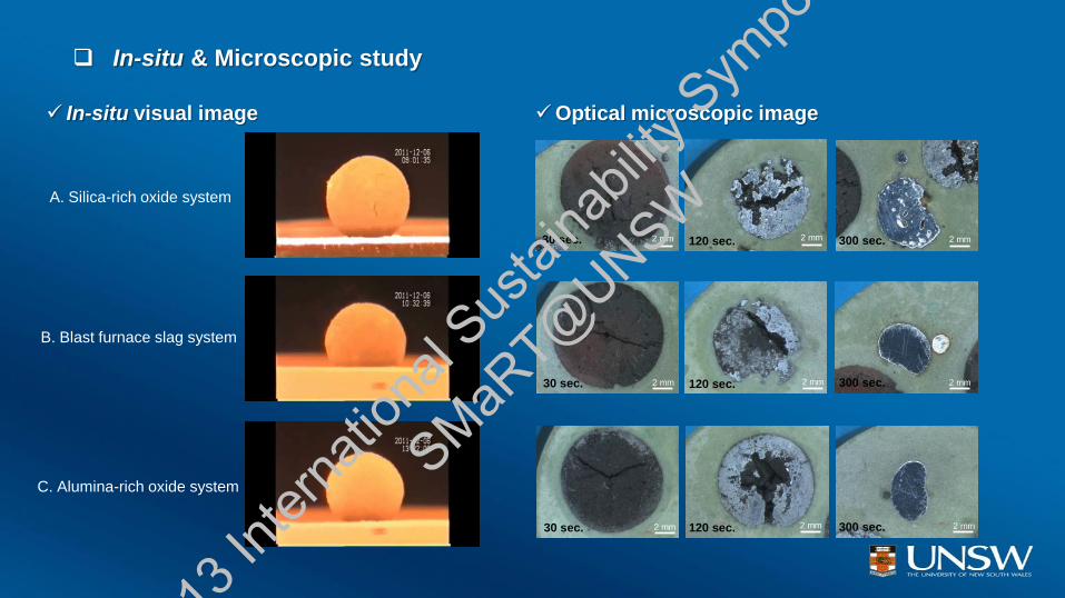
A. Silica-rich oxide system
C. Alumina-rich oxide system
B. Blast furnace slag system
In-situ visual image Optical microscopic image
120 sec. 300 sec.
30 sec. 120 sec.
30 sec. 120 sec.
30 sec.
300 sec.
300 sec.
2 mm
2 mm 2 mm 2 mm
2 mm 2 mm
2 mm 2 mm 2 mm
In-situ & Microscopic study
2013
Inter
natio
nal S
ustai
nabil
ity S
ympo
sium
SMaRT@
UNSW
25 30 35 40 45 50
30sec
0sec
120sec
Fe2O
3 Fe free C
Inte
nsity
2 theta
25 30 35 40 45 50
30sec
0sec
120sec
Fe2O
3 Fe free C
Inte
nsity
2 theta
25 30 35 40 45 50
30sec
0sec
120sec
Fe2O
3 Fe free C
Inte
nsity
2 theta
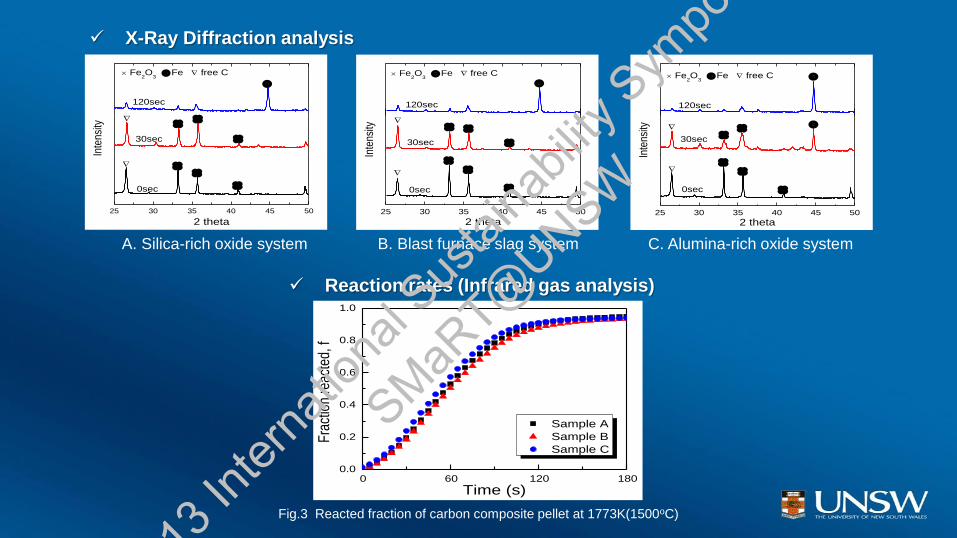
X-Ray Diffraction analysis
Reaction rates (Infrared gas analysis)
0 60 120 1800.0
0.2
0.4
0.6
0.8
1.0
Sample A
Sample B
Sample C
Fra
ctio
n re
acte
d, f
Time (s)
A. Silica-rich oxide system C. Alumina-rich oxide system B. Blast furnace slag system
Fig.3 Reacted fraction of carbon composite pellet at 1773K(1500oC)
2013
Inter
natio
nal S
ustai
nabil
ity S
ympo
sium
SMaRT@
UNSW
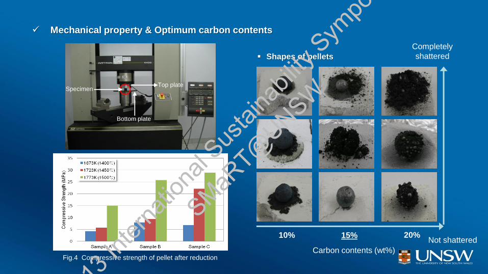
Specimen Top plate
Bottom plate
Mechanical property & Optimum carbon contents
10% 15% 20%
Carbon contents (wt%)
Completely
shattered
Not shattered
Shapes of pellets
Fig.4 Compressive strength of pellet after reduction
2013
Inter
natio
nal S
ustai
nabil
ity S
ympo
sium
SMaRT@
UNSW
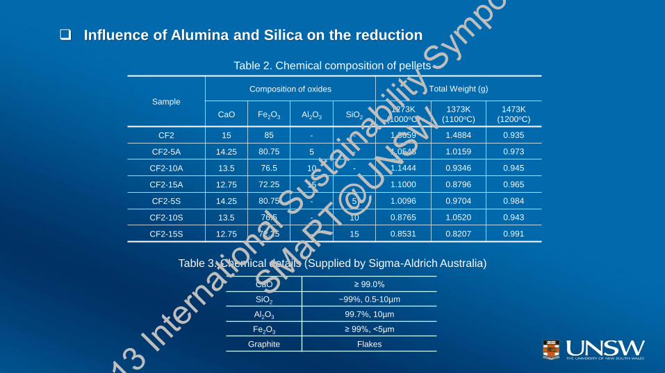
Table 2. Chemical composition of pellets
Sample
Composition of oxides Total Weight (g)
CaO Fe2O3 Al2O3 SiO2
1273K
(1000oC)
1373K
(1100oC)
1473K
(1200oC)
CF2 15 85 - - 1.3659 1.4884 0.935
CF2-5A 14.25 80.75 5 - 1.0548 1.0159 0.973
CF2-10A 13.5 76.5 10 - 1.1444 0.9346 0.945
CF2-15A 12.75 72.25 15 - 1.1000 0.8796 0.965
CF2-5S 14.25 80.75 - 5 1.0096 0.9704 0.984
CF2-10S 13.5 76.5 - 10 0.8765 1.0520 0.943
CF2-15S 12.75 72.25 - 15 0.8531 0.8207 0.991
CaO ≥ 99.0%
SiO2 ~99%, 0.5-10µm
Al2O3 99.7%, 10µm
Fe2O3 ≥ 99%, <5µm
Graphite Flakes
Table 3. Chemical details (Supplied by Sigma-Aldrich Australia)
Influence of Alumina and Silica on the reduction
2013
Inter
natio
nal S
ustai
nabil
ity S
ympo
sium
SMaRT@
UNSW
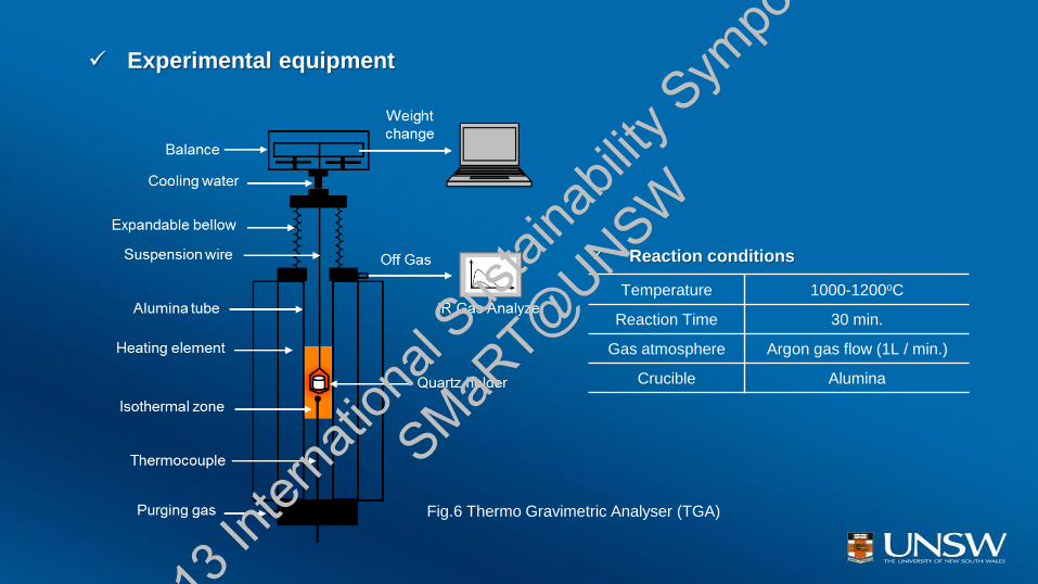
Temperature 1000-1200oC
Reaction Time 30 min.
Gas atmosphere Argon gas flow (1L / min.)
Crucible Alumina
Experimental equipment
Fig.6 Thermo Gravimetric Analyser (TGA)
Reaction conditions
2013
Inter
natio
nal S
ustai
nabil
ity S
ympo
sium
SMaRT@
UNSW

Temperature dependence
0 600 1200 1800 2400 3000 36000
20
40
60
80
100
GR-L (Graphite) - 1473K (1200OC)
CB-1 (Coke) - 1273K (1000OC)
Jeremy and Veena
CF2-1473K (1200oC)
CF2-1373K (1100oC)
CF2-1273K (1000oC)
Reduction d
egre
e (
%)
Time (sec.)
Fig.7 Temperature dependences of reduction degree for CF2
sample compared to previous research
Thermodynamic & kinetic study
0 100 200 300 400 500 6000.55
0.60
0.65
0.70
0.75
0.80
0.85
0.90
0.95
#1 CF2
#2 CF2 Al2O
3 5wt%
#3 CF2 Al2O
310wt%
#4 CF2 Al2O
315wt%
#5 CF2 SiO2 5wt%
#6 CF2 SiO210wt%
#7 CF2 SiO215wt%
Wei
ght (
g)
Time (sec.)
Fig. 8 - Effect of Al2O3 and SiO2 on the weight loss
of carbon composite pellets during reduction at 1200oC
Weight loss
2013
Inter
natio
nal S
ustai
nabil
ity S
ympo
sium
SMaRT@
UNSW
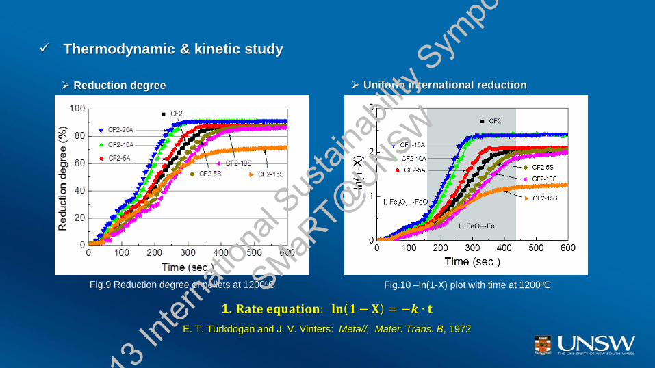
Thermodynamic & kinetic study
Reduction degree Uniform international reduction
1. 𝐑𝐚𝐭𝐞 𝐞𝐪𝐮𝐚𝐭𝐢𝐨𝐧: 𝐥𝐧 𝟏 − 𝐗 = −𝒌 ∙ 𝐭
E. T. Turkdogan and J. V. Vinters: Meta//, Mater. Trans. B, 1972
Fig.9 Reduction degree of pellets at 1200oC Fig.10 –ln(1-X) plot with time at 1200oC
2013
Inter
natio
nal S
ustai
nabil
ity S
ympo
sium
SMaRT@
UNSW
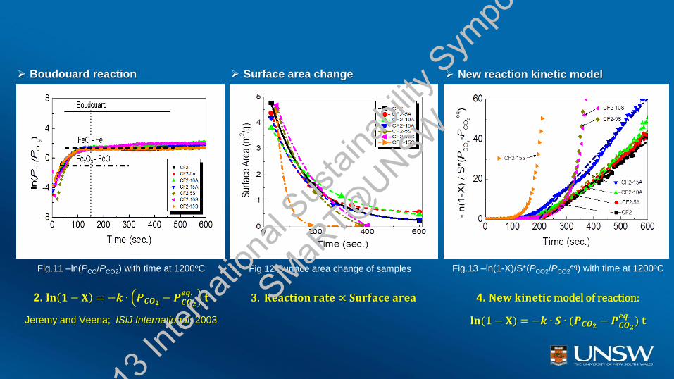
Surface area change New reaction kinetic model Boudouard reaction
2. 𝐥𝐧 𝟏 − 𝐗 = −𝒌 ∙ 𝑷𝑪𝑶𝟐− 𝑷𝑪𝑶𝟐
𝒆𝒒.𝐭
Jeremy and Veena; ISIJ International, 2003
4. 𝐍𝐞𝐰 𝐤𝐢𝐧𝐞𝐭𝐢𝐜 model of reaction:
𝐥𝐧(𝟏 − 𝐗) = −𝒌 ∙ 𝑺 ∙ (𝑷𝑪𝑶𝟐− 𝑷𝑪𝑶𝟐
𝒆𝒒.) 𝐭
𝟑. 𝐑𝐞𝐚𝐜𝐭𝐢𝐨𝐧 𝐫𝐚𝐭𝐞 ∝ 𝐒𝐮𝐫𝐟𝐚𝐜𝐞 𝐚𝐫𝐞𝐚
Fig.11 –ln(PCO/PCO2) with time at 1200oC Fig.12 Surface area change of samples Fig.13 –ln(1-X)/S*(PCO2/PCO2eq) with time at 1200oC
2013
Inter
natio
nal S
ustai
nabil
ity S
ympo
sium
SMaRT@
UNSW
20 30 40 50 60 70 80 90
Inte
nsi
ty
RD 80%
RD 30%
RD 5%
CaO Fe2O
3 Fe
2 theta
CF2 (1473K)
20 30 40 50 60 70 80 90
Inte
nsi
ty
RD 80%
RD 30%
RD 5%
CaAl2O
4 Fe
2O
3 Fe
2 theta
CF2-15A (1473K)
20 30 40 50 60 70 80 90
Inte
nsi
ty
RD 80%
RD 30%
RD 5%
Fe2SiO
4 Fe
2O
3 Fe
2 theta
CF2-15S (1473K)
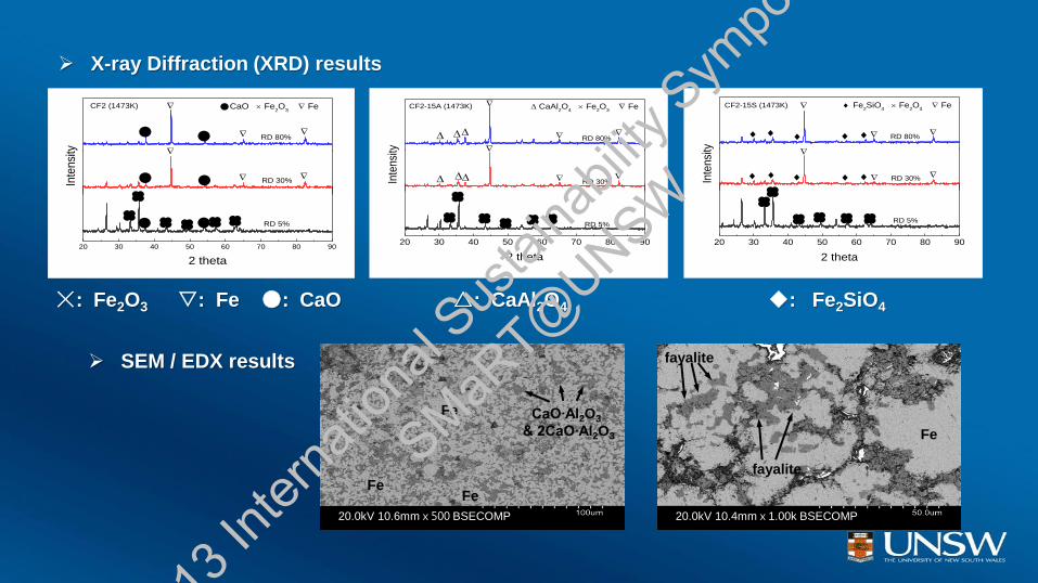
X-ray Diffraction (XRD) results
20.0kV 10.4mmⅹ1.00k BSECOMP
Fe
fayalite
fayalite
20.0kV 10.6mmⅹ500 BSECOMP
Fe CaO∙Al2O3
& 2CaO∙Al2O3
Fe
Fe
☓: Fe2O3 : Fe ●: CaO △: CaAl2O4 ◆: Fe2SiO4
SEM / EDX results
2013
Inter
natio
nal S
ustai
nabil
ity S
ympo
sium
SMaRT@
UNSW
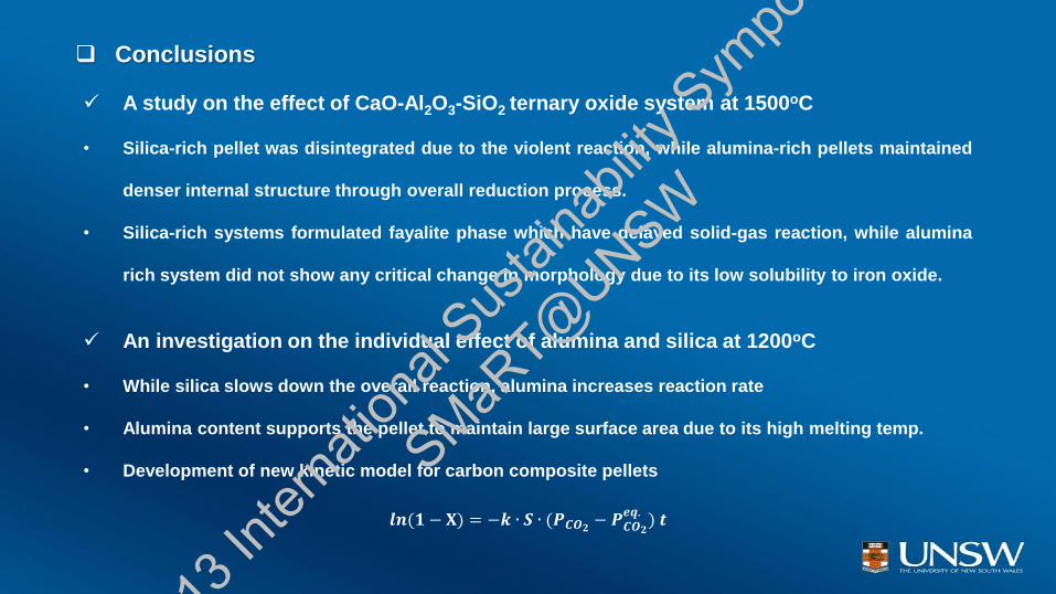
Conclusions
A study on the effect of CaO-Al2O3-SiO2 ternary oxide system at 1500oC
• Silica-rich pellet was disintegrated due to the violent reaction, while alumina-rich pellets maintained
denser internal structure through overall reduction process.
• Silica-rich systems formulated fayalite phase which have delayed solid-gas reaction, while alumina
rich system did not show any critical change in morphology due to its low solubility to iron oxide.
An investigation on the individual effect of alumina and silica at 1200oC
• While silica slows down the overall reaction, alumina increases reaction rate
• Alumina content supports the pellet to maintain large surface area due to its high melting temp.
• Development of new kinetic model for carbon composite pellets
𝒍𝒏(𝟏 − 𝐗) = −𝒌 ∙ 𝑺 ∙ (𝑷𝑪𝑶𝟐− 𝑷𝑪𝑶𝟐
𝒆𝒒.) 𝒕
2013
Inter
natio
nal S
ustai
nabil
ity S
ympo
sium
SMaRT@
UNSW
Thank you for attention
2013
Inter
natio
nal S
ustai
nabil
ity S
ympo
sium
SMaRT@
UNSW