smith-purcell free electron laser: a compact terhertz source
TRANSCRIPT

Smith-Purcell Free Electron Laser: A Compact Terhertz Source
Vinit KumarRaja Ramanna Centre for Advanced Technology
Indore
March 15, 2019
Symposium on coherence in particle and photon beams: Past, Present and FutureArgonne National Laboratory 1

In this talk, rather than making a review of Smith-Purcell
free-electron lasers, I am going to share some of the things
I learnt while working with Kwang-Je during 2003-05, and
which continued ….
2

Outline of the talk
I. Motivation for Smith-Purcell (SP) FELs
II. Surface Mode in SP-FEL
III. Beam-wave interaction in SP-FEL
IV. Example cases of SP-FEL as terahertz source
V. Conclusions3

Coherent terahertz radiation can be produced using undulator based FELs.
But, we need high energy electron accelerator (~5-10 MeV), with radiation shielding.
Can we use low energy electron beam for terahertz generation?
Undulator based FEL with low energy?
Need to use microundulators. Very low K.Gain will be low. FELs typically requirehigh peak current, so bunched beam isneeded.
𝜆𝜆𝑅𝑅 =𝜆𝜆𝑢𝑢
2𝛾𝛾2 (1 +𝐾𝐾2
2 ) 𝐾𝐾 =𝑒𝑒𝐵𝐵𝑢𝑢𝜆𝜆𝑢𝑢2𝜋𝜋𝜋𝜋𝜋𝜋
Motivation for Smith-Purcell FELs
4
Can we use slow wave structures,such as grating or dielectric basedstructures for this purpose?
If yes, why has it not been done sofar. What are the challenges.
Slow wave FEL with low energy?
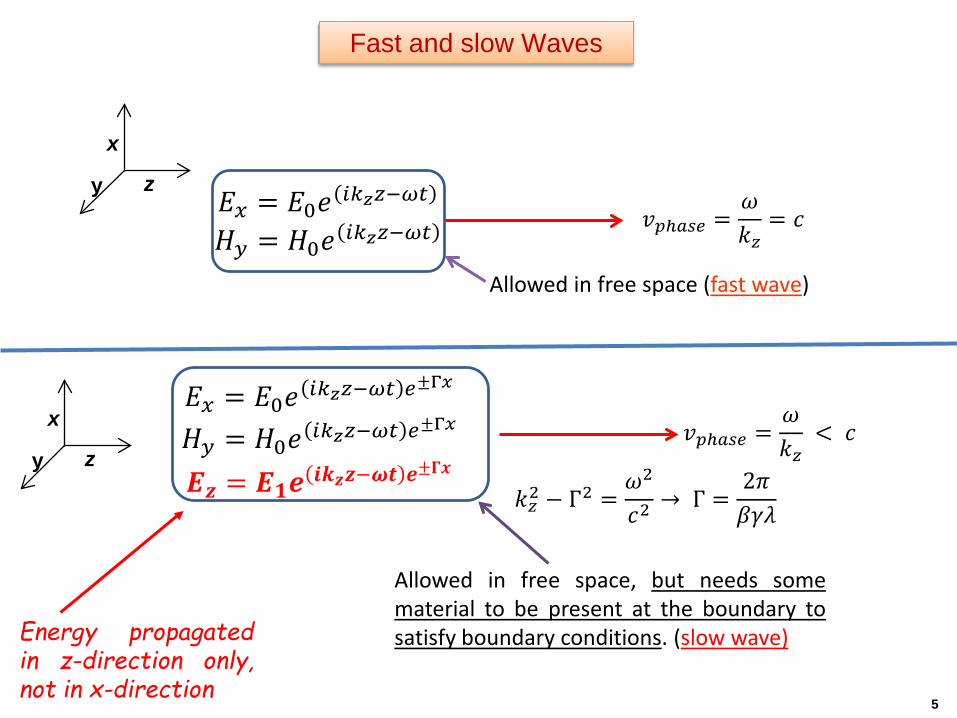
𝑣𝑣𝑝𝑝𝑝𝑝𝑝𝑝𝑝𝑝𝑝 =𝜔𝜔𝑘𝑘𝑧𝑧
= 𝜋𝜋
Allowed in free space (fast wave)
x
y z𝐸𝐸𝑥𝑥 = 𝐸𝐸0𝑒𝑒 𝑖𝑖𝑘𝑘𝑧𝑧𝑧𝑧−𝜔𝜔𝜔𝜔
𝐻𝐻𝑦𝑦 = 𝐻𝐻0𝑒𝑒 𝑖𝑖𝑘𝑘𝑧𝑧𝑧𝑧−𝜔𝜔𝜔𝜔
Fast and slow Waves
5
𝑘𝑘𝑧𝑧2 − Γ2 =𝜔𝜔2
𝜋𝜋2 → Γ =2𝜋𝜋𝛽𝛽𝛾𝛾𝜆𝜆
𝑣𝑣𝑝𝑝𝑝𝑝𝑝𝑝𝑝𝑝𝑝 =𝜔𝜔𝑘𝑘𝑧𝑧
< 𝜋𝜋
Allowed in free space, but needs somematerial to be present at the boundary tosatisfy boundary conditions. (slow wave)
𝐸𝐸𝑥𝑥 = 𝐸𝐸0𝑒𝑒 𝑖𝑖𝑘𝑘𝑧𝑧𝑧𝑧−𝜔𝜔𝜔𝜔 𝑝𝑝±Γ𝑥𝑥
𝐻𝐻𝑦𝑦 = 𝐻𝐻0𝑒𝑒 𝑖𝑖𝑘𝑘𝑧𝑧𝑧𝑧−𝜔𝜔𝜔𝜔 𝑝𝑝±Γ𝑥𝑥
𝑬𝑬𝒛𝒛 = 𝑬𝑬𝟏𝟏𝒆𝒆 𝒊𝒊𝒌𝒌𝒛𝒛𝒛𝒛−𝝎𝝎𝝎𝝎 𝒆𝒆±𝚪𝚪𝚪𝚪
Energy propagatedin z-direction only,not in x-direction
x
y z

A modulated sheet electron beam moving with constant speed produces slow waves, decaying away in the transverse direction*
0
])(exp[)(2
])(exp[)()(2
])(exp[)()(21
0000
0
0000
0
000
===
Γ−Γ−
=
Γ−=
Γ−=
Iz
Ix
Iy
Iz
Ix
Iy
HHE
xxziKiE
xxziKxE
xxziKxH
εαωωε
εαωεωεα
εαωε
ε(x) = -1 for x < 0
+1 for x > 0
βγλπβγω
ωα
/2// 222
00
==
−=Γ
cc
These are slow plane waves, propagating along z-axis with speed v, but decaying along x-axis with length scale of βγλ/2π . These are non-radiating, zeroth order evanescent wave.
Slow waves generated by a modulated sheet electron beam
* K.-J. Kim and S. -B. Song, NIMA 475 (2001) 158.
𝐽𝐽𝑧𝑧 = 𝛿𝛿(𝑥𝑥)𝐾𝐾0(𝜔𝜔) exp[ 𝑖𝑖(𝛼𝛼0𝑧𝑧 − 𝜔𝜔𝑡𝑡]
x
y z
6
Hy
Hy

Evanescent waves generated by uniformly moving charge and its reflection
1916-2011
7

),( xz kk),( xz kk −
0ne
),( ngz pnkk +00 , α=Γ−= zx kik
For some values of n (<0), kx and kz are real, those are SP radiation orders.
∑∞+
−∞=
−++
−Γ+=
nnn
Rn
Iy
tixipziA
tixziAH
)exp(
)exp( 000
ωα
ωα
x
y z
22
2
)( gzn nkkc
p +−=ω
real →propagating, radiative
imaginary→ evanescent, non-radiative
Reflection of evanescent wave by a metallic reflection grating
8
Diffraction at the grating surface
9

Phys. Rev. paper by Smith-Purcell
1912-1997
10
11
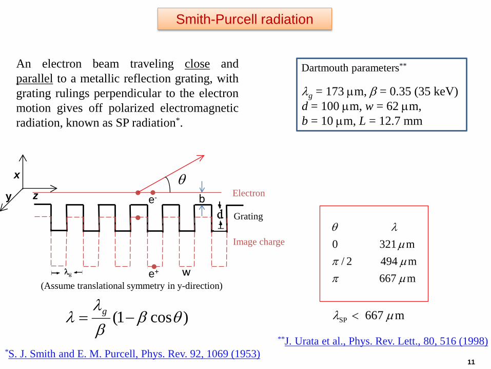
An electron beam traveling close andparallel to a metallic reflection grating, withgrating rulings perpendicular to the electronmotion gives off polarized electromagneticradiation, known as SP radiation*.
)cos1( θββλ
λ −= g m667SP µλ <
*S. J. Smith and E. M. Purcell, Phys. Rev. 92, 1069 (1953)
m667m4942/m3210
µπµπµ
λθ
**J. Urata et al., Phys. Rev. Lett., 80, 516 (1998)
x
y z
Image charge
Electron
Grating
θe-
e+
(Assume translational symmetry in y-direction)
λg = 173 µm, β = 0.35 (35 keV)d = 100 µm, w = 62 µm, b = 10 µm, L = 12.7 mm
Dartmouth parameters**
Smith-Purcell radiation
b
w

12
SEM-based Smith-Purcell FEL?
(J. Urata et al., PRL 80 (1998) 516-519)
Is it an FEL?
Phys. Rev. Lett. paper by Urata and Walsh

13
“Smith-Purcell FEL Lab” at the Univ. of Chicago following the Dartmouth set-up (O. Kapp, A. Crewe, Y.E. Sun, V. Kumar, KJK)
β= 0.35 (35 keV)Ι = 1 mΑλg = 173 µm, d = 100 mm, w = 62 µm, b = 10 µm, L = 12.7 mm
May 11-12 2015
KJK US-Korea mmW/THz Round Table
13
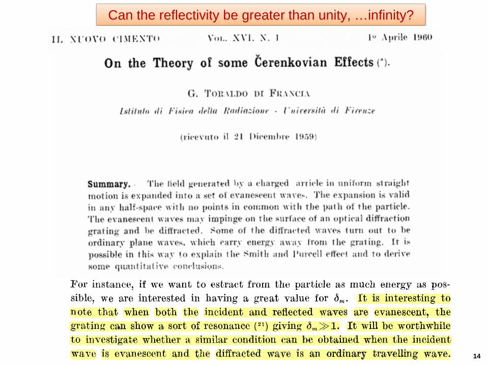
Can the reflectivity be greater than unity, …infinity?
14

•e00 blows up at λ = 690 µm which means that the zeroth order outgoing wave issupported there even in the absence of incoming wave.
∑ −Γ−= )exp( tixziCH snnnSMy ωα
λ = 690 µm
λs = βλ = 241.5 µm
*V. Kumar and K.-J. Kim, PAC05 proceedings, Phys Rev. E 73, 026501(2006)
λg = 173 µm, β = 0.35 (35 keV)
groove depth (d) = 100 µm,
groove width (w) = 62 µm,
Dartmouth parameters**
•In fact, zeroth order wave and all higher order outgoing components add up withspecific amplitude ratio to satisfy the boundary condition. This is the surface modesupported self-consistently by the grating
Singularity in reflectivity and surface mode in SP-FEL
15
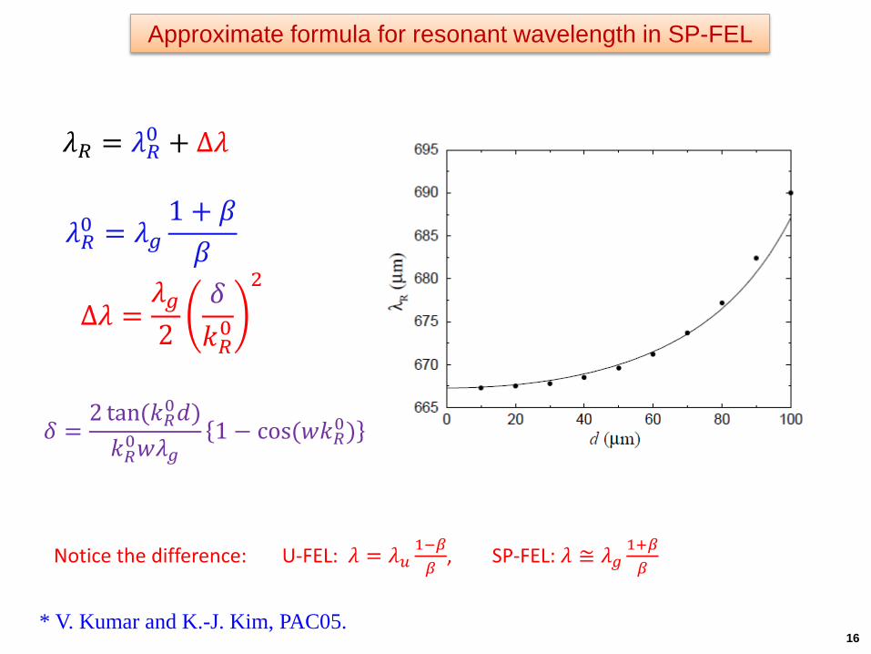
𝜆𝜆𝑅𝑅0 = 𝜆𝜆𝑔𝑔1 + 𝛽𝛽𝛽𝛽
𝜆𝜆𝑅𝑅 = 𝜆𝜆𝑅𝑅0 + Δ𝜆𝜆
Δ𝜆𝜆 =𝜆𝜆𝑔𝑔2
𝛿𝛿𝑘𝑘𝑅𝑅0
2
𝛿𝛿 =2 tan(𝑘𝑘𝑅𝑅0𝑑𝑑)𝑘𝑘𝑅𝑅0𝑤𝑤𝜆𝜆𝑔𝑔
1 − cos(𝑤𝑤𝑘𝑘𝑅𝑅0)
Notice the difference: U-FEL: 𝜆𝜆 = 𝜆𝜆𝑢𝑢1−𝛽𝛽𝛽𝛽
, SP-FEL: 𝜆𝜆 ≅ 𝜆𝜆𝑔𝑔1+𝛽𝛽𝛽𝛽
* V. Kumar and K.-J. Kim, PAC05.
Approximate formula for resonant wavelength in SP-FEL
16

Interaction between slow wave and the co-propagating electronbeam produces coherent radiation
Group velocity is typically -ve, works as abackward wave oscillator.
Beam-wave interaction
17
Boundary condition: Input field needs to beprovided at the electron beam exit!

•We observe that the singularity in Ris removed at non-zero growth rate (µ)of the incident wave.
𝐸𝐸𝑍𝑍 = 𝐸𝐸0𝑒𝑒 𝑖𝑖𝑘𝑘𝑧𝑧𝑧𝑧−𝜔𝜔𝜔𝜔 𝑒𝑒Γ𝑥𝑥𝑒𝑒𝜇𝜇𝑧𝑧
•R has a simple pole at µ = 0, and itcan be expressed as
1)( χµχµ +
−=
iR
*V. Kumar and K.-J. Kim, PRE 73 (2006)026501; Y. Kalkal and V.Kumar, PRSTAB 18 (2015)030707.
Singularity of reflection coefficient
18
χ = 10 per cm, χ1= 1.37

Surface current: ..)/( )( cceeyI tzkii ss +∆ −− ωψ
Axial electric field: ..),( )( ccetzE tzkiz
ss +−ω
scsuribbz EEeeei
yiIZE +=
−+
−∆
= −Γ−Γ− ψχµχ
βγ1
200 2
120
( ) ψ
βγib
z eRey
iIZE −Γ− −∆
= 12
020
Slow-wave structure
Maxwell-Lorentz equations - I
19

A novel approach!
20
[40]. R. J. Pierce, Traveling Wave Tubes (D. Van Nostrand Company Inc; First edition, 1950)

Time-dependent Maxwell equation:
( ) ψ
ψ
χβγ
βγχ
ibsc
ibgg
eey
iIZE
eey
vIZzEv
tE
−Γ−
−Γ−
−∆
−=
∆−=
∂∂
−∂∂
0
0
21
0
20
12
2
Lorentz equation:
( )( )
p
pisii
iscii
zv
t
cceEEmcev
zv
ti
γγγ
γβωψψ
γγ ψ
−=
∂∂
+∂
∂
++=∂∂
+∂∂
22
2 ..
No attenuation No end reflection No 3-D effects
ψ
βγχµ ibsur eey
IZE −Γ−
∆= 020
2
Replacing µ with the operator d/dz, we get
ψ
βγχ ib
suree
yIZ
dzdE −Γ−
∆= 020
2
Maxwell-Lorentz equations - II
21

Maxwell-Lorentz equations with attenuation and end reflections
Dimensionless variables:
( )
b
pp
s
A
spp
ss
pp
s
pipp
si
gpp
eLkyI
IJ
Ec
Lkmc
e
Ec
Lkmc
e
Lk
Lvvvz
Lz
0244
3
33
2
2
33
2
2
33
1
2
111
/
Γ−
−
∆=
=
=
−=
+
−=
=
γβχπ
γβε
γβε
γγγβ
η
ττ
ς
( )
( ) ψ
ψ
ψ
χχ
ε
ης
ψ
εεςη
εαςε
τε
εαςε
τε
ibsc
ii
isci
i
eeL
Ji
cce
Ld
LeJ
i
−Γ
+
+++
−−−−
−=
=∂
∂
++=∂∂
−=∂∂
+∂∂
−−=∂∂
−∂∂
021
1
..
Maxwell-Lorentz equations indimensionless variables:
Boundary conditions:
),0(),0(
),,1(),1(02 τςετςε
τςετςε
===
=−==
+−
−
−+
LkieR
*V. Kumar and K.-J. Kim, Proceedings of FEL06
gp
gp
vvvv
d−
+=
+
1
- wavebackward: waveforward:
εε
Maxwell-Lorentz equations with attenuation and end reflections
22

•Particles initialized as per Penman’salgorithm to take care of shot noise
•Particle pushing for known field usingpredictor-corrector method.
•Convert P. D. E for field to differenceequation and updated the field using thedifference equation
τ
ς
τ∆j
ς∆n
*Our algorithm is similar to N. S. Ginzburg et al., Sov. Radiophys. Electron., 21, 728 (1979).
•Grid parameters:∆τ = 0.01 ⇒ t = 2.02 ps∆ζ = 0.02, Npart = 1024
0 1
80
Numerical simulations
23
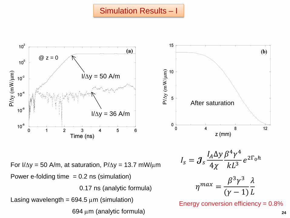
I/∆y = 50 A/m
I/∆y = 36 A/mAfter saturation
@ z = 0
Energy conversion efficiency = 0.8%
For I/∆y = 50 A/m, at saturation, P/∆y = 13.7 mW/µm
Power e-folding time = 0.2 ns (simulation)
0.17 ns (analytic formula)
Lasing wavelength = 694.5 µm (simulation)
694 µm (analytic formula)
Simulation Results – I
24
𝐼𝐼𝑝𝑝 = 𝓙𝓙𝑝𝑝𝐼𝐼𝐴𝐴Δ𝑦𝑦4𝜒𝜒
𝛽𝛽4𝛾𝛾4
𝑘𝑘𝐿𝐿3𝑒𝑒2Γ0𝑝
𝜂𝜂𝑚𝑚𝑝𝑝𝑥𝑥 =𝛽𝛽3𝛾𝛾3
(𝛾𝛾 − 1)𝜆𝜆𝐿𝐿

Bunching in Smith-Purcell FEL
Simulation Results – II
25
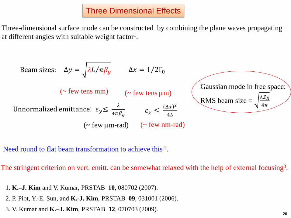
The stringent criterion on vert. emitt. can be somewhat relaxed with the help of external focusing3.
Gaussian mode in free space:
RMS beam size = 𝜆𝜆𝑍𝑍𝑅𝑅4𝜋𝜋
𝜖𝜖𝑥𝑥 ≤Δ𝑥𝑥 2
4𝐿𝐿Unnormalized emittance: 𝜖𝜖𝑦𝑦≤
𝜆𝜆4𝜋𝜋𝛽𝛽𝑔𝑔
Beam sizes: Δ𝑦𝑦 = ⁄𝜆𝜆𝐿𝐿 𝜋𝜋𝛽𝛽𝑔𝑔 Δ𝑥𝑥 = ⁄1 2Γ0
(~ few tens mm) (~ few tens µm)
(~ few µm-rad) (~ few nm-rad)
Need round to flat beam transformation to achieve this 2.
Three Dimensional Effects
Three-dimensional surface mode can be constructed by combining the plane waves propagating at different angles with suitable weight factor1.
1. K.–J. Kim and V. Kumar, PRSTAB 10, 080702 (2007).
3. V. Kumar and K.–J. Kim, PRSTAB 12, 070703 (2009).
2. P. Piot, Y.-E. Sun, and K.-J. Kim, PRSTAB 09, 031001 (2006).
26

Relaxed beam parameters with external focusing1
Grating parameters:λg = 173 µm, d = 130 mm, w = 110 µm, L = 38.06 mmλR = 761 mm
Beam parameters:β= 0.35 (35 keV)Ι = 30 mΑ∆y = 45.6 µm∆x = 7 mmβγεx = 10-5 mradβγεy = 10-7mrad
1. V. Kumar and K.–J. Kim, PRSTAB 12, 070703 (2009).
Wiggler2:λw = 2.7 mm, gap = 1 mm, Bpk = 4.7 kG
2. V. A. Papadichev V. E. Rybalchenko, NIMA 19, 407 (1998).
Similar performance can be achieved also by using a solenoid (instead of wiggler) having a field of 2.5 kG tofocus the electron beam, the flat beam in that case should be generated using a line cathode. The line cathodefollowed by a reflection grating should be immersed together in the uniform field region of the solenoid.
27

• Smith-Purcell FELs seem to be interesting and useful alternative to undulator based FELs for compact sources of terahertz radiation.
• SP-FEL can be described by Maxwell-Lorentz equations of the form similar to that ofundulator based FELs. Effect of attenuation and diffraction are particulary important,and can not be ignored.
• Main challenge in achieving successful lasing in SP-FEL is to meet the stringent critera onbeam quality. Flat beam with low emittance in vertical direction is needed.
• If the challenge on beam quality is met in future, it appears that SP-FELs will be very usefulas a compact source to generate average power of the order of Watt at terahertzwavelengths.
Conclusions
28


