smootharc elite mma 162 vrd - boc...ewm hightec welding – germany’s leading manufacturer and...
TRANSCRIPT

Operating instructions
Welding machine
Smootharc Elite MMA 162 VRD
099-002050-BOC01 30.11.2009

General instructions
CAUTION
Read the operating instructions! The operating instructions provide an introduction to the safe use of the products. • Read the operating instructions for all system components! • Observe accident prevention regulations! • Observe all local regulations! • Confirm with a signature where appropriate.
NOTE
In the event of queries on installation, commissioning, operation or special conditions at the installation site, or on usage, please contact your sales partner or our customer service department on +61 (02) 8874 4721. A list of authorised sales partners can be found at www.boc.com.au or www.boc.co.nz
Liability relating to the operation of this equipment is restricted solely to the function of the equipment. No other form of liability, regardless of type, shall be accepted. This exclusion of liability shall be deemed accepted by the user on commissioning the equipment. The manufacturer is unable to monitor whether or not these instructions or the conditions and methods are observed during installation, operation, usage and maintenance of the equipment. An incorrectly performed installation can result in material damage and injure persons as a result. For this reason, we do not accept any responsibility or liability for losses, damages or costs arising from incorrect installation, improper operation or incorrect usage and maintenance or any actions connected to this in any way.
© 2009 The copyright to this document remains the property of the manufacturer. Reprinting, including extracts, only permitted with written approval. Subject to technical amendments.

Dear Customer
Premium quality with a three-year warranty - Five year warranty on transformers and rectifiers
Congratulations on purchasing a BOC SMOOTHARC ELITE machine. You have chosen a quality product from EWM Hightec Welding – Germany’s leading manufacturer and technology expert of arc welding machines.
These machines provide results of the highest perfection thanks to their PREMIUM quality. Therefore, we are happy to provide you with a full 3-year warranty (five year warranty on transformers and rectifiers) according to the operating instructions.
In all their high-tech components, these welding machines embody future-oriented advanced technology at the utmost level of quality. Each of these products is carefully checked; EWM guarantee that the material and processing of these products is faultless.
These operating instructions contain everything about commissioning the machine, notes regarding safety, maintenance and care, technical data as well as information regarding the warranty. Please heed all these notes to ensure many years of safe operation of the machine.
Thank you for the trust that you have placed in us. We look forward to a long-term partnership with you.
Yours sincerely
Bruce Currie
Marketing Director - South Pacific
BOC Limited

Contents Notes on the use of these operating instructions
4 099-002050-BOC0130.11.2009
1 Contents
1 Contents ..................................................................................................................................................4 2 Safety instructions .................................................................................................................................6
2.1 Notes on the use of these operating instructions...........................................................................6 2.2 General...........................................................................................................................................8 2.3 Transport and installation.............................................................................................................11 2.4 Ambient conditions.......................................................................................................................12
2.4.1 In operation...................................................................................................................12 2.4.2 Transport and storage ..................................................................................................12
3 Intended use .........................................................................................................................................13 3.1 Applications..................................................................................................................................13 3.2 Documents which also apply........................................................................................................13
3.2.1 Warranty .......................................................................................................................13 3.2.2 Declaration of Conformity .............................................................................................13 3.2.3 Welding in environments with increased electrical hazards .........................................13 3.2.4 Service documents (spare parts and circuit diagrams) ................................................13
4 Machine description – quick overview...............................................................................................14 4.1 Smootharc Elite MMA 162 VRD...................................................................................................14
4.1.1 Front view .....................................................................................................................14 4.1.2 Rear view......................................................................................................................15
4.2 Machine control – Operating elements ........................................................................................16 5 Design and function.............................................................................................................................17
5.1 General.........................................................................................................................................17 5.2 Installation ....................................................................................................................................18 5.3 Machine cooling ...........................................................................................................................18 5.4 Workpiece lead, general ..............................................................................................................18 5.5 Mains connection .........................................................................................................................19
5.5.1 Mains configuration.......................................................................................................19 5.6 MMA welding................................................................................................................................20
5.6.1 Connecting the electrode holder and workpiece lead ..................................................20 5.6.2 Selecting MMA welding ................................................................................................21 5.6.3 Arcforce.........................................................................................................................21 5.6.4 Hotstart device..............................................................................................................21 5.6.5 Antistick.........................................................................................................................21
5.7 TIG welding ..................................................................................................................................22 5.7.1.1 Connecting a TIG welding torch with rotating gas valve ...............................22 5.7.1.2 Connection for workpiece lead......................................................................22 5.7.1.3 Shielding Gas Supply ....................................................................................23
5.7.2 TIG welding selection ...................................................................................................23 5.7.3 TIG arc ignition .............................................................................................................24
5.8 Voltage reducing device...............................................................................................................24 5.9 Dirt filter ........................................................................................................................................25

Contents
Notes on the use of these operating instructions
099-002050-BOC01 30.11.2009
5
6 Maintenance, care and disposal.........................................................................................................26 6.1 General ........................................................................................................................................26 6.2 Maintenance work, intervals ........................................................................................................26
6.2.1 Daily maintenance tasks ..............................................................................................26 6.2.2 Monthly maintenance tasks..........................................................................................26 6.2.3 Annual test (inspection and testing during operation) ..................................................26
6.3 Repair Work .................................................................................................................................27 6.4 Meeting the requirements of RoHS .............................................................................................27
7 Rectifying faults ...................................................................................................................................28 7.1 Machine faults (error messages) .................................................................................................28 7.2 Customer checklist.......................................................................................................................28
8 Technical data ......................................................................................................................................29 8.1 Smootharc Elite MMA 162 ...........................................................................................................29
9 Accessories, options ...........................................................................................................................30 9.1 General accessories ....................................................................................................................30

Safety instructions Notes on the use of these operating instructions
6 099-002050-BOC0130.11.2009
2 Safety instructions 2.1 Notes on the use of these operating instructions
DANGER
Working or operating procedures which must be closely observed to prevent imminent serious and even fatal injuries. • Safety notes include the "DANGER" keyword in the heading with a general warning symbol. • The hazard is also highlighted using a symbol on the edge of the page.
WARNING
Working or operating procedures which must be closely observed to prevent serious and even fatal injuries. • Safety notes include the "WARNING" keyword in the heading with a general warning
symbol. • The hazard is also highlighted using a symbol in the page margin.
CAUTION
Working or operating procedures which must be closely observed to prevent possible minor personal injury. • The safety information includes the "CAUTION" keyword in its heading with a general
warning symbol. • The risk is explained using a symbol on the edge of the page.
CAUTION
Working and operating procedures which must be followed precisely to avoid damaging or destroying the product. • The safety information includes the "CAUTION" keyword in its heading without a general
warning symbol. • The hazard is explained using a symbol at the edge of the page.
NOTE
Special technical points which users must observe. • Notes include the "NOTE" keyword in the heading without a general warning symbol. • Notes are highlighted using a "hand" symbol at the edge of the page.

Safety instructions
Notes on the use of these operating instructions
099-002050-BOC01 30.11.2009
7
Instructions and lists detailing step-by-step actions for given situations can be recognised via bullet points, e.g.: • Insert the welding current lead socket into the relevant socket and lock.
Symbol Description
Press
Do not press
Turn
Switch
01
Switch off machine
01
Switch on machine
ENTER (enter the menu)
NAVIGATION (Navigating in the menu)
EXIT (Exit the menu)
Time display (example: wait 4s/press)
Interruption in the menu display (other setting options possible)
Tool not required/do not use
Tool required/use

Safety instructions General
8 099-002050-BOC0130.11.2009
2.2 General
DANGER
Electromagnetic fields! The power source may cause electrical or electromagnetic fields to be produced which could affect the correct functioning of electronic equipment such as IT or CNC devices, telecommunication lines, power cables, signal lines and pacemakers. • Observe the maintenance instructions! (see Maintenance and Testing chapter) • Unwind welding lines completely! • Shield devices or equipment sensitive to radiation accordingly! • The correct functioning of pacemakers may be affected (obtain advice from a doctor if
necessary).
Do not carry out any unauthorised repairs or modifications! To avoid injury and equipment damage, the unit must only be repaired or modified by specialist, skilled persons! The warranty becomes null and void in the event of unauthorised interference. • Appoint only skilled persons for repair work (trained service personnel)!
Electric shock! Welding machines use high voltages which can result in potentially fatal electric shocks and burns on contact. Even low voltages can cause you to get a shock and lead to accidents. • Do not touch any live parts in or on the machine! • Connection cables and leads must be free of faults! • Switching off alone is not sufficient! • Place welding torch and stick electrode holder on an insulated surface! • The unit should only be opened by specialist staff after the mains plug has been unplugged!• Only wear dry protective clothing! • Wait for 4 minutes until the capacitors have discharged!
WARNING
Risk of injury due to radiation or heat! Arc radiation results in injury to skin and eyes. Contact with hot workpieces and sparks results in burns. • Wear dry protective clothing (e.g. welding shield, gloves, etc.) according to the relevant
regulations in the country in question! • Protect persons not involved in the work against arc beams and the risk of glare using safety
curtains!
Explosion risk! Apparently harmless substances in closed containers may generate excessive pressure when heated. • Move containers with inflammable or explosive liquids away from the working area! • Never heat explosive liquids, dusts or gases by welding or cutting!

Safety instructions
General
099-002050-BOC01 30.11.2009
9
WARNING
Smoke and gases! Smoke and gases can lead to breathing difficulties and poisoning. In addition, solvent vapour (chlorinated hydrocarbon) may be converted into poisonous phosgene due to the ultraviolet radiation of the arc! • Ensure that there is sufficient fresh air! • Keep solvent vapour away from the arc beam field! • Wear suitable breathing apparatus if appropriate!
Fire hazard! Flames may arise as a result of the high temperatures, stray sparks, glowing-hot parts and hot slag produced during the welding process. Stray welding currents can also result in flames forming! • Check for fire hazards in the working area! • Do not carry any easily flammable objects such as matches or lighters. • Keep appropriate fire extinguishing equipment to hand in the working area! • Thoroughly remove any residue of flammable substances from the workpiece before starting
welding. • Only continue work on welded workpieces once they have cooled down.
Do not allow to come into contact with flammable material! • Connect welding leads correctly!
Risk of accidents if these safety instructions are not observed! Non-observance of these safety instructions is potentially fatal! • Carefully read the safety information in this manual! • Observe the accident prevention regulations in your country. • Inform persons in the working area that they must observe the regulations!
CAUTION
Noise exposure! Noise exceeding 70 dBA can cause permanent hearing damage! • Wear suitable ear protection! • Persons located within the working area must wear suitable ear protection!

Safety instructions General
10 099-002050-BOC0130.11.2009
CAUTION
Obligations of the operator! In the European Economic Area (EEA), the relevant national version of the basic guidelines must be followed and observed! • National version of the basic guidelines (89/391/EEC) as well as the relevant individual
guidelines. • Please note that under no circumstances should any equipment or parts be altered or
changed in any way from the standard specification without written permission given by BOC. To do so, will void the Equipment Warranty.
• Further information can be obtained from Welding Institute of Australia (WTIA) Technical Note No.7 ´Health and Safety Welding` Published by WTIA, PO Box 6165 Silverwater NSW 2128 Phone (02) 9748 4443.
Damage due to the use of non-genuine parts! The manufacturer's warranty becomes void if non-genuine parts are used! • Only use system components and options (power sources, welding torches, electrode
holders, remote controls, spare parts and replacement parts, etc.) from our range of products!
• Only insert and lock accessory components into the relevant connection socket when the machine is switched off.
Electromagnetic interference! The machines are intended to be used in industrial areas, according to IEC 60974-10. If they are used in residential areas, for example, problems may occur with ensuring electromagnetic compatibility. • Check whether interference is caused to other machines!

Safety instructions
Transport and installation
099-002050-BOC01 30.11.2009
11
2.3 Transport and installation
WARNING
Incorrect handling of shielding gas cylinders! Incorrect handling of shielding gas cylinders can result in serious and even fatal injury. • Observe the instructions from the gas manufacturer and in any relevant regulations
concerning the use of compressed air! • Place shielding gas cylinders in the holders provided for them and secure with fixing
devices. • Avoid heating the shielding gas cylinder!
CAUTION
Risk of tipping! There is a risk of the machine tipping over and injuring persons or being damaged itself during movement and set up. Tilt resistance is guaranteed up to an angle of 10° (according to IEC 60974-1, -3, -10). • Set up and transport the machine on level, solid ground. • Secure add-on parts using suitable equipment.
Damage due to supply lines not being disconnected! During transport, supply lines which have not been disconnected (mains supply leads, control leads, etc.) may cause hazards such as connected equipment tipping over and injuring persons! • Disconnect supply lines!
CAUTION
Equipment damage when not operated in an upright position! The units are designed for operation in an upright position! Operation in non-permissible positions can cause equipment damage. • Only transport and operate in an upright position!
Safety instructions Ambient conditions
12 099-002050-BOC0130.11.2009
2.4 Ambient conditions
CAUTION
Installation site! The machine must not be operated in the open air and must only be set up and operated on a suitable, stable and level base! • The operator must ensure that the ground is non-slip and level, and provide sufficient
lighting for the place of work. • Safe operation of the machine must be guaranteed at all times.
CAUTION
Equipment damage due to dirt accumulation! Unusually high quantities of dust, acid, corrosive gases or substances may damage the equipment. • Avoid high volumes of smoke, vapour, oil vapour and grinding dust! • Avoid ambient air containing salt (sea air)!
Non-permissible ambient conditions! Insufficient ventilation results in a reduction in performance and equipment damage. • Observe the ambient conditions! • Keep the cooling air inlet and outlet clear! • Observe the minimum distance of 0.5 m from obstacles!
2.4.1 In operation Temperature range of the ambient air: • -20 °C to +40 °C Relative air humidity: • Up to 50% at 40 °C • Up to 90% at 20 °C
2.4.2 Transport and storage Storage in an enclosed space, temperature range of the ambient air: • -25 °C to +55 °C Relative air humidity • Up to 90% at 20 °C

Intended use
Applications
099-002050-BOC01 30.11.2009
13
3 Intended use This machine has been manufactured according to the latest developments in technology and current regulations and standards. It must only be operated in line with the instructions on correct usage.
WARNING
Hazards due to improper usage! Hazards may arise for persons, animals and material objects if the equipment is not used correctly. No liability is accepted for any damages arising from improper usage! • The equipment must only be used in line with proper usage and by trained or expert staff! • Do not modify or convert the equipment improperly!
3.1 Applications This welding machine is suitable only for MMA and TIG welding with liftarc. • MMA direct current welding for rutile, rutile/basic, basic and rutile/cellulose electrode types.
3.2 Documents which also apply 3.2.1 Warranty
NOTE
For further information, please see the accompanying supplementary sheets "Machine and Company Data, Maintenance and Testing, Warranty"!
3.2.2 Declaration of Conformity
The designated machine conforms to EC Directives and standards in terms of its design and construction: • EC Low Voltage Directive (2006/95/EC), • EC EMC Directive (2004/108/EC),
This declaration shall become null and void in the event of unauthorised modifications, improperly conducted repairs, non-observance of the deadlines for the repetition test and / or non-permitted conversion work not specifically authorised by the manufacturer. The original copy of the declaration of conformity is enclosed with the unit.
3.2.3 Welding in environments with increased electrical hazards
In compliance with IEC / DIN EN 60974, VDE 0544 the machines can be used in environments with an increased electrical hazard.
3.2.4 Service documents (spare parts and circuit diagrams)
DANGER
Do not carry out any unauthorised repairs or modifications! To avoid injury and equipment damage, the unit must only be repaired or modified by specialist, skilled persons! The warranty becomes null and void in the event of unauthorised interference. • Appoint only skilled persons for repair work (trained service personnel)!
Original copies of the circuit diagrams are enclosed with the unit. Spare parts can be obtained from the relevant authorised dealer.
Machine description – quick overview Smootharc Elite MMA 162 VRD
14 099-002050-BOC0130.11.2009
4 Machine description – quick overview 4.1 Smootharc Elite MMA 162 VRD 4.1.1 Front view
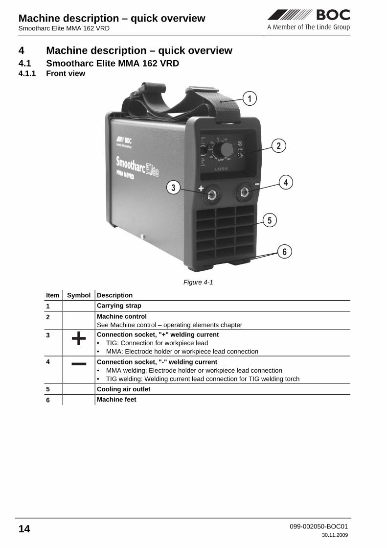
Figure 4-1
Item Symbol Description 0
1 Carrying strap
2 Machine control See Machine control – operating elements chapter
3
Connection socket, "+" welding current • TIG: Connection for workpiece lead • MMA: Electrode holder or workpiece lead connection
4 Connection socket, "-" welding current • MMA welding: Electrode holder or workpiece lead connection • TIG welding: Welding current lead connection for TIG welding torch
5 Cooling air outlet
6 Machine feet

Machine description – quick overview
Smootharc Elite MMA 162 VRD
099-002050-BOC01 30.11.2009
15
4.1.2 Rear view
Figure 4-2
Item Symbol Description 0
1 Mains connection cable
2
Main switch, machine on/off
3 Cooling air inlet
Machine description – quick overview Machine control – Operating elements
16 099-002050-BOC0130.11.2009
4.2 Machine control – Operating elements
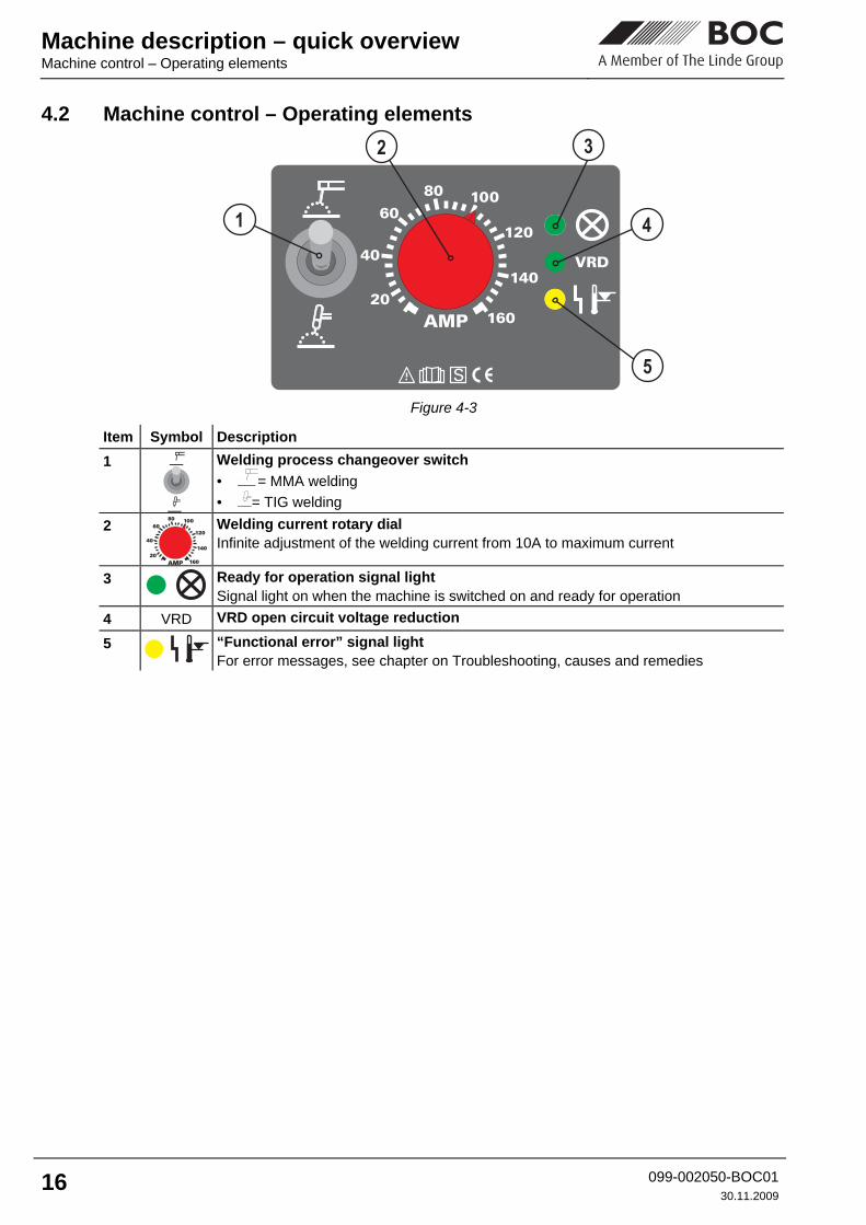
Figure 4-3
Item Symbol Description 0
1
Welding process changeover switch • = MMA welding • = TIG welding
2
20
40
6080 100
120
140
160AMP
Welding current rotary dial Infinite adjustment of the welding current from 10A to maximum current
3
Ready for operation signal light Signal light on when the machine is switched on and ready for operation
4 VRD VRD open circuit voltage reduction
5
“Functional error” signal light For error messages, see chapter on Troubleshooting, causes and remedies
Design and function
General
099-002050-BOC01 30.11.2009
17
5 Design and function 5.1 General
DANGER
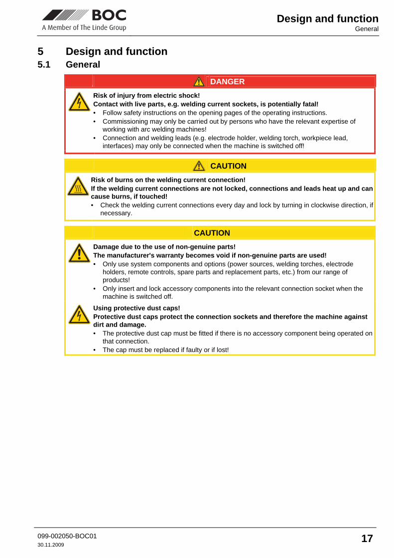
Risk of injury from electric shock! Contact with live parts, e.g. welding current sockets, is potentially fatal! • Follow safety instructions on the opening pages of the operating instructions. • Commissioning may only be carried out by persons who have the relevant expertise of
working with arc welding machines! • Connection and welding leads (e.g. electrode holder, welding torch, workpiece lead,
interfaces) may only be connected when the machine is switched off!
CAUTION
Risk of burns on the welding current connection! If the welding current connections are not locked, connections and leads heat up and can cause burns, if touched! • Check the welding current connections every day and lock by turning in clockwise direction, if
necessary.
CAUTION
Damage due to the use of non-genuine parts! The manufacturer's warranty becomes void if non-genuine parts are used! • Only use system components and options (power sources, welding torches, electrode
holders, remote controls, spare parts and replacement parts, etc.) from our range of products!
• Only insert and lock accessory components into the relevant connection socket when the machine is switched off.
Using protective dust caps! Protective dust caps protect the connection sockets and therefore the machine against dirt and damage. • The protective dust cap must be fitted if there is no accessory component being operated on
that connection. • The cap must be replaced if faulty or if lost!
Design and function Installation
18 099-002050-BOC0130.11.2009
5.2 Installation
CAUTION
Installation site! The machine must not be operated in the open air and must only be set up and operated on a suitable, stable and level base! • The operator must ensure that the ground is non-slip and level, and provide sufficient
lighting for the place of work. • Safe operation of the machine must be guaranteed at all times.
5.3 Machine cooling To obtain an optimal duty cycle from the power components, the following precautions should be observed: • Ensure that the working area is adequately ventilated. • Do not obstruct the air inlets and outlets of the machine. • Do not allow metal parts, dust or other objects to get into the machine.
5.4 Workpiece lead, general
CAUTION
Risk of burns due to incorrect connection of the workpiece lead! Paint, rust and dirt on the connection restrict the power flow and may lead to stray welding currents. Stray welding currents may cause fires and injuries! • Clean the connections! • Fix the workpiece lead securely! • Do not use structural parts of the workpiece as a return lead for the welding current! • Take care to ensure faultless power connections!

Design and function
Mains connection
099-002050-BOC01 30.11.2009
19
5.5 Mains connection
DANGER
Hazard caused by improper mains connection! An improper mains connection can cause injuries or damage property! • Only use machine with a plug socket that has a correctly fitted protective conductor. • If a mains plug must be fitted, this may only be carried out by an electrician in accordance
with the relevant national provisions or regulations (any phase sequence for three-phase machines)!
• Mains plug, socket and lead must be checked regularly by an electrician!
5.5.1 Mains configuration
NOTE
The machine may be connected and operated on all TN or TT networks with a neutral conductor and a protective conductor.
L1NPE
Figure 5-1 Legend Item Designation Colour code L1 Outer conductor brown
N Neutral conductor blue
PE Protective conductor green-yellow
CAUTION
Operating voltage - mains voltage! The operating voltage shown on the rating plate must be consistent with the mains voltage, in order to avoid damage to the machine! • For mains fuse protection, please refer to the “Technical data” chapter!
• Insert mains plug of the switched-off machine into the appropriate socket.

Design and function MMA welding
20 099-002050-BOC0130.11.2009
5.6 MMA welding
CAUTION
Risk of being crushed or burnt. When replacing spent or new stick electrodes • Switch off machine at the main switch • Wear appropriate safety gloves • Use insulated tongs to remove spent stick electrodes or to move welded workpieces and • Always put the electrode holder down on an insulated surface.
5.6.1 Connecting the electrode holder and workpiece lead
Figure 5-2
Item Symbol Description 0
1
Connection socket, "+" welding current • TIG: Connection for workpiece lead • MMA: Electrode holder or workpiece lead connection
2 “-” Welding current connection socket Electrode holder or workpiece lead connection
• Insert cable plug of the electrode holder into either the "+" or "-" welding current connection socket and lock by turning to the right.
• Insert cable plug of the workpiece lead into either the "+" or "-" welding current connection socket and lock by turning to the right.
NOTE
Polarity depends on the instructions from the electrode manufacturer given on the electrode packaging.
Design and function
MMA welding
099-002050-BOC01 30.11.2009
21
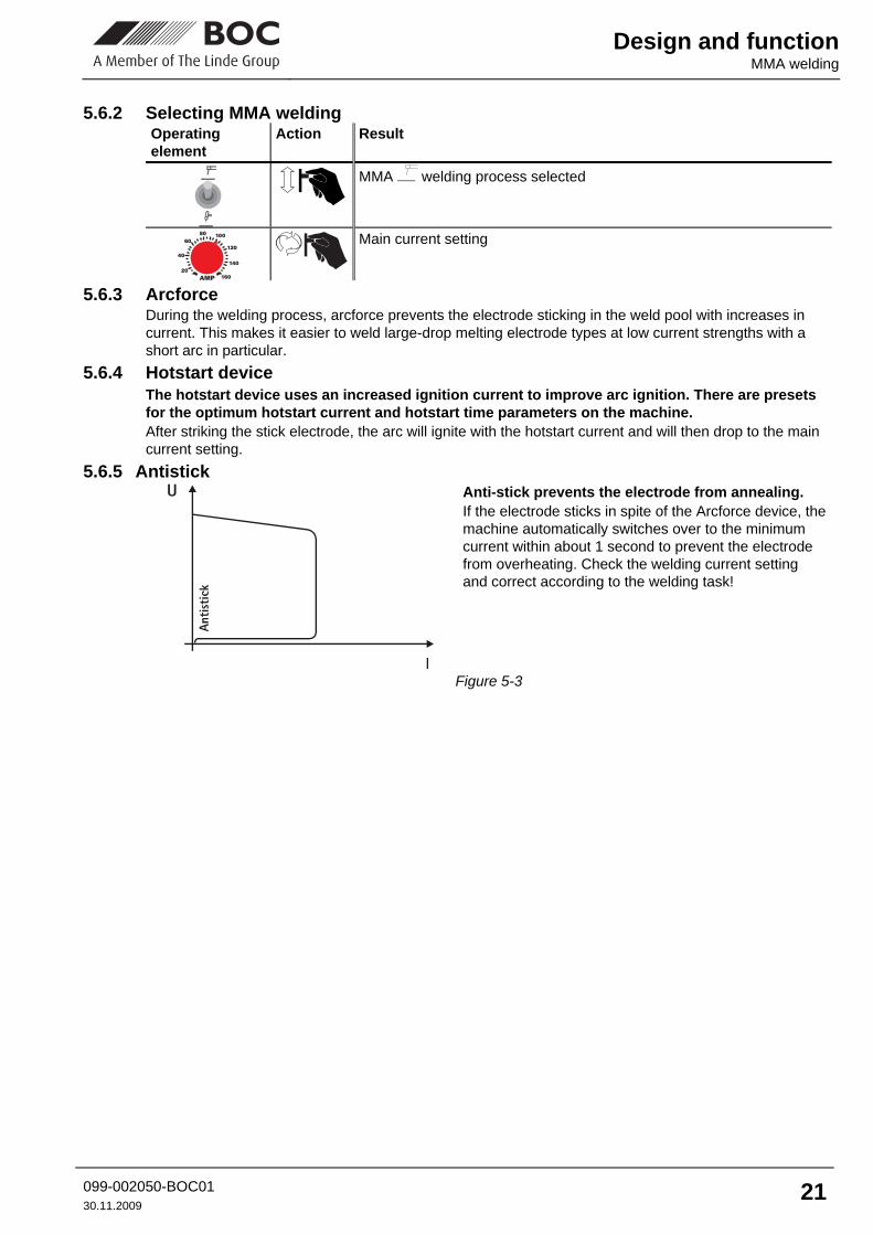
5.6.2 Selecting MMA welding Operating element
Action Result
MMA welding process selected
20
40
6080 100
120
140
160AMP
Main current setting
5.6.3 Arcforce During the welding process, arcforce prevents the electrode sticking in the weld pool with increases in current. This makes it easier to weld large-drop melting electrode types at low current strengths with a short arc in particular.
5.6.4 Hotstart device The hotstart device uses an increased ignition current to improve arc ignition. There are presets for the optimum hotstart current and hotstart time parameters on the machine. After striking the stick electrode, the arc will ignite with the hotstart current and will then drop to the main current setting.
5.6.5 Antistick
Anti-stick prevents the electrode from annealing. If the electrode sticks in spite of the Arcforce device, the machine automatically switches over to the minimum current within about 1 second to prevent the electrode from overheating. Check the welding current setting and correct according to the welding task!
Figure 5-3

Design and function TIG welding
22 099-002050-BOC0130.11.2009
5.7 TIG welding
NOTE
Prepare welding torch according to the welding task in hand (see operating instructions for the torch).
Figure 5-4
Item Symbol Description 0
1
Connection socket, “+” welding current Connection for workpiece lead
2 “-” Welding current connection socket TIG welding torch welding current lead connection
5.7.1.1 Connecting a TIG welding torch with rotating gas valve When pausing work, always place the welding torch on an insulated surface. Prepare the welding torch according to the welding task in hand (see torch operating instructions). The welding torch shielding gas is supplied directly from the shielding gas cylinder. • Fit the tungsten electrode and gas nozzle onto the welding torch (observe current load, see torch
operating instructions). • Insert the welding current plug into the “-” welding current connection socket and lock by turning to the
right. 5.7.1.2 Connection for workpiece lead
• Insert the cable plug on the work piece lead into the "+" welding current connection socket and lock by turning to the right.

Design and function
TIG welding
099-002050-BOC01 30.11.2009
23
5.7.1.3 Shielding Gas Supply
WARNING
Incorrect handling of shielding gas cylinders! Incorrect handling of shielding gas cylinders can result in serious and even fatal injury. • Observe the instructions from the gas manufacturer and in any relevant regulations
concerning the use of compressed air! • Place shielding gas cylinders in the holders provided for them and secure with fixing
devices. • Avoid heating the shielding gas cylinder!
CAUTION
Faults in the shielding gas supply. An unhindered shielding gas supply from the shielding gas cylinder to the welding torch is a fundamental requirement for optimum welding results. In addition, a blocked shielding gas supply may result in the welding torch being destroyed. • Always re-fit the yellow protective cap when not using the shielding gas connection. • All shielding gas connections must be gas tight.
NOTE
Before connecting the pressure reducer to the gas cylinder, open the cylinder valve briefly to expel any dirt.
• Tighten the pressure reducer screw connection on the gas bottle valve to be gas-tight. • Tighten gas hose on pressure reducer to be gas tight.
• Slowly open the gas cylinder valve. • Open the rotating valve on the welding torch Before each welding process, the rotating valve must be opened; after the welding process, it must be closed. • Set the required amount of shielding gas on the pressure reducer, about 4 - 15 l/min depending on the
current strength and the material. Rule of thumb for gas flow rate: Diameter of gas nozzle in mm corresponds to gas flow in l/min. Example: 7 mm gas nozzle corresponds to 7 l/min gas flow
5.7.2 TIG welding selection Operating Element
Action Result
TIG welding process selected
20
40
6080 100
120
140
160AMP
Main current setting

Design and function Voltage reducing device
24 099-002050-BOC0130.11.2009
5.7.3 TIG arc ignition
a) b) c)
Figure 5-5 The arc is ignited on contact with the workpiece: a) Carefully place the torch gas nozzle and tungsten electrode tip onto the workpiece (liftarc current
flowing, regardless of the main current set). b) Incline the torch towards the torch gas nozzle until there is a gap of approx. 2-3mm between the tip of
the electrode and the workpiece (arc ignites, current increases to the main current set). c) Lift off the torch and swivel to the normal position. Ending the welding process: Remove the torch from the workpiece until the arc goes out.
5.8 Voltage reducing device The signal light (VRD open circuit voltage reduction) indicates when the voltage reduction device has been activated. This then ensures that the open circuit voltage between the electrode holder and the workpiece is reduced to the permissible values. The voltage reducing device is a requirement in some countries and in many internal company safety guidelines for power sources.
Design and function
Dirt filter
099-002050-BOC01 30.11.2009
25
5.9 Dirt filter
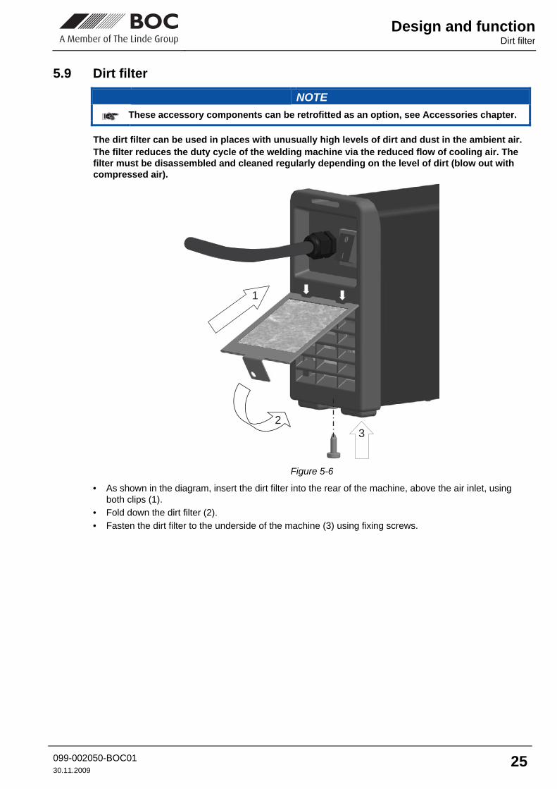
NOTE
These accessory components can be retrofitted as an option, see Accessories chapter.
The dirt filter can be used in places with unusually high levels of dirt and dust in the ambient air. The filter reduces the duty cycle of the welding machine via the reduced flow of cooling air. The filter must be disassembled and cleaned regularly depending on the level of dirt (blow out with compressed air).
2
3
1
Figure 5-6 • As shown in the diagram, insert the dirt filter into the rear of the machine, above the air inlet, using
both clips (1). • Fold down the dirt filter (2). • Fasten the dirt filter to the underside of the machine (3) using fixing screws.

Maintenance, care and disposal General
26 099-002050-BOC0130.11.2009
6 Maintenance, care and disposal
DANGER
Risk of injury from electric shock! Cleaning machines that are not disconnected from the mains can lead to serious injuries!• Disconnect the machine completely from the mains. • Remove the mains plug! • Wait for 4 minutes until the capacitors have discharged!
6.1 General When used in the specified environmental conditions and under normal operating conditions, this machine is largely maintenance-free and requires a minimum of care. There are some points, which should be observed, to guarantee fault-free operation of your welding machine. Among these are regular cleaning and checking as described below, depending on the pollution level of the environment and the length of time the unit is in use.
6.2 Maintenance work, intervals 6.2.1 Daily maintenance tasks
• Mains supply lead and its strain relief • Welding current cables (check that they are fitted correctly and secured) • Operating, message, safety and adjustment devices • Other, general condition
6.2.2 Monthly maintenance tasks • Casing damage (front, rear and side walls) • Transport elements (strap, lifting lugs, handle) • Selector switches, command devices, emergency stop devices, voltage reducing devices, message
and control lamps
6.2.3 Annual test (inspection and testing during operation)
NOTE
The welding machine may only be tested by competent, capable personsl. A capable person is one who, because of his training, knowledge and experience, is able to recognise the dangers that can occur while testing welding power sources as well as possible subsequent damage and who is able to implement the required safety procedures.
The former term of repetition test has been replaced due to a change in the corresponding standard with “Inspection and testing during operation”. In addition to the regulations on the test given here, the relevant local laws and regulations must also be observed.
NOTE
For further information, please see the accompanying supplementary sheets "Machine and Company Data, Maintenance and Testing, Warranty"!
Maintenance, care and disposal
Repair Work
099-002050-BOC01 30.11.2009
27
6.3 Repair Work
DANGER
Do not carry out any unauthorised repairs or modifications! To avoid injury and equipment damage, the unit must only be repaired or modified by specialist, skilled persons! The warranty becomes null and void in the event of unauthorised interference. • Appoint only skilled persons for repair work (trained service personnel)!
Repair and maintenance work may only be performed by qualified authorised personnel; otherwise the right to claim under warranty is void. In all service matters, always consult the dealer who supplied the machine. Return deliveries of defective equipment subject to warranty may only be made through your dealer. When replacing parts, use only original spare parts. When ordering spare parts, please quote the machine type, serial number and item number of the machine, as well as the type designation and item number of the spare part.
6.4 Meeting the requirements of RoHS We, EWM HIGHTEC Welding GmbH Mündersbach, hereby confirm that all products supplied by us which are affected by the RoHS Directive, meet the requirements of the RoHS (Directive 2002/95/EC).
Rectifying faults Machine faults (error messages)
28 099-002050-BOC0130.11.2009
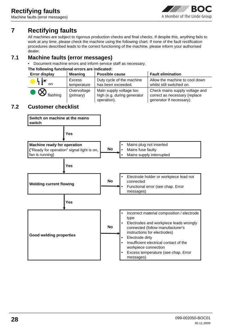
7 Rectifying faults All machines are subject to rigorous production checks and final checks. If despite this, anything fails to work at any time, please check the machine using the following chart. If none of the fault rectification procedures described leads to the correct functioning of the machine, please inform your authorised dealer.
7.1 Machine faults (error messages) • Document machine errors and inform service staff as necessary. The following functional errors are indicated: Error display Meaning Possible cause Fault elimination
on Excess temperature
Duty cycle of the machine has been exceeded.
Allow the machine to cool down whilst still switched on.
flashing Overvoltage (primary)
Main supply voltage too high (e.g. during generator operation).
Check mains supply voltage and correct as necessary (replace generator if necessary).
7.2 Customer checklist
Switch on machine at the mains switch
Yes
Machine ready for operation ("Ready for operation" signal light is on, fan is running)
No
• Mains plug not inserted • Mains fuse faulty • Mains supply interrupted
Yes
Welding current flowing
No
• Electrode holder or workpiece lead not connected
• Functional error (see chap. Error messages)
Yes
Good welding properties
No
• Incorrect material composition / electrode type
• Electrodes and workpiece leads wrongly connected (follow manufacturer’s instructions for electrodes)
• Electrode dirty • Insufficient electrical contact of the
workpiece connection • Excess temperature (see chap. Error
messages)

Technical data
Smootharc Elite MMA 162
099-002050-BOC01 30.11.2009
29
8 Technical data 8.1 Smootharc Elite MMA 162
MMA TIG
Setting range Welding current 10 A to 150 A 10 A to 160 A
Setting range Welding voltage 20.4 V to 26.0 V 10.4 V to 16.4 V
Duty cycle at 25 °C 45 % 50 % 100 %
-
150 A 120 A
160 A
- 120 A
Duty cycle at 40 °C 30 % 35 % 60 % 100 %
-
150 A 120 A 100 A
160 A
- 130 A 100 A
Load alternation 10 min (60% DC ∧ 6 min welding, 4 min idle)
Open circuit voltage 105 V
Open circuit voltage (VRD) 33 V
Mains voltage (tolerances) 1 x 230 V (-40% to +15%)
Frequency 50/60 Hz
Mains fuse (safety fuse, slow-blow) 16 A
Mains connection lead H07RN-F3G2.5
Max. connected power 5,5 kVA 3,7 kVA
Recommended generator rating 7,5 kVA
cosϕ at Imax 0.99
Insulation class / protection classification H / IP 23
Ambient temperature -20°C to +40°C
Machine cooling / torch cooling Fan / Gas
Workpiece lead 16 qmm
Dimensions L/W/H 430 x 116 x 224 mm
Weight 4.8 kg
Constructed to standards IEC 60974-1, -3, -10 /

Accessories, options General accessories
30 099-002050-BOC0130.11.2009
9 Accessories, options 9.1 General accessories
Type Description / Name ADAP 16/25-35 QMM Welding current socket adapter
from 16/25 to 30 QMM
ON FILTER Retrofit option, dirt filter for air inlet