smos esa/cnes operations: multiplying two agencies’ efforts
TRANSCRIPT

1
SMOS ESA/CNES operations: Multiplying two agencies’ efforts
Guillermo Buenadicha1 ESA‐ESAC, European Space Agency, European Space Astronomy Centre, Villanueva de la Cañada, Madrid, 28691
Spain
Sandrine Burgaud2, Bertrand Raffier3, CNES, French Space Agency, Operations Entity, Toulouse, 31401, France
and
Blanca Sánchez Rojo4 INSA‐ESAC, Ingeniería y Servicios Aeroespaciales S.A. Paseo Pintor Rosales 34, 28008, Madrid, Spain
SMOS is the second ESA Earth Explorer mission, and was developed in collaboration with the French Space Agency, (CNES) and the Spanish Centro para el Desarrollo Tecnológico Industrial (CDTI). This collaborative approach continues in the operations phase: ESA is responsible for the overall mission operations, instrument and ground segment operations whereas CNES is responsible for the space segment operations including satellite platform and satellite operations ground segment (SOGS). The payload of SMOS consists of the Microwave Imaging Radiometer using Aperture Synthesis (MIRAS) instrument. The mission and payload design is such that the interactions and dependencies of MIRAS and the PROTEUS platform are highly reduced to power, time synchronisation, TM and TC routing, plus attitude and orbit control at platform side and some high level safety mechanisms. Both the payload and the platform implement their own independent sets of services. The paper presents the operational concept for the SMOS mission, and how it has evolved from the pre‐launch concept into a matured one after more than 2 years into the mission. SMOS operations and success are linked to the merge of operational cultures of two Agencies, and this mixture of different mechanism, systems, procedures and organizations has demonstrated to be more productive than just the simple sum of its terms. The paper also gives some operational examples along the SMOS lifetime, and aims to extract some set of lessons learnt for future cooperation inter agencies.
I. SMOS Mission HE Soil Moisture and Ocean Salinity (SMOS) mission, launched on 2 November 2009 from the Plesetsk
Cosmodrome (Russia), is the European Space Agency’s (ESA) second Earth Explorer Opportunity mission within its Living Planet Programme1. The SMOS mission is the Explorer devoted to gain a better understanding of the water cycle. Its objectives are : (1) To provide global volumetric soil moisture estimates with an accuracy of 0.04 m3m-3 at a spatial resolution of 35-50 km and a temporal sampling of 1-3 days and (2) To provide global ocean salinity estimates with an accuracy of 0.1 practical salinity scale units for a 10-30 day average for an open ocean area of 200 x 200 km22. The SMOS mission is based on a sun-synchronous orbit (dusk-dawn 6 am/6 pm) with a mean altitude of 758 km and an inclination of 98.44◦. SMOS has a 149-day repeat cycle with a 3-day sub-cycle1.
1 SMOS Payload Operations Manager, ESA HSO-OEX, [email protected]. 2 SMOS Spacecraft Operations Manager, CNES DCT-OP-M2, [email protected]. 3 SMOS Spacecraft Operations Engineer, CNES DCT-SB-PS, [email protected]. 4 SMOS Payload Mission Planning Engineer, ESA EOP-GTA, [email protected].
T

2
SMOS was developed in collaboration with the French Space Agency, the Centre National d'Etudes Spatiales (CNES), and the Spanish Centro para el Desarrollo Tecnológico Industrial (CDTI). This collaborative approach continues in the operations phase: ESA is responsible for the overall mission operations, instrument and ground segment operations whereas CNES is responsible for the operations of the satellite3.
II. Operations Concept ESA is primarily responsible for the overall mission and ground segment operations. CNES is primarily
responsible for the operations of the satellite, the SOGS, and the French CATDS. The ESA Payload Operations Team is responsible for the payload operations and coordinates the interface between the platform operations led by CNES and the payload operations led by ESA. The CNES team is responsible for the overall space segment operations (including satellite and SOGS). CNES is also in charge of the control, trend analysis and maintenance as well as performance assessments of the platform3.
A. Platform and Instrument The SMOS platform was the 5th element of the PROTEUS series
jointly developed by Thales Alenia Space and the CNES. This platform, already used for Oceanography, Cloud Aerosol Observation, Astroseismology and Exoplanets Detection since more than 20 cumulated years in orbit, is based on the following generic principles as: (1) Large range of accessible low orbits (500km < a < 1500 km and 15°< i < 14°) and pointing (inertial, geocentric, yaw-steering). (2) Payload characteristics in the range 100 – 300 kg. (3) High independence between platform and payload management, allowing a decoupled approach between mission centers and control center. (4) Good level of redundancy and availability, with a large autonomy. And (5) delivery of several services to a given number of different payload units: power, precise datation (PPS at 5 ms), thermal control, monitoring, telemetry storage (2 Gbit dedicated to the payload), command ability.
The SMOS instrument, MIRAS, comparable in size and weight to that of the platform, is an innovative L Band radio-interferometer3,4 with a Y shape antenna array (8 meters diameter), manufactured by EADS-CASA Spain5. It is composed by an array of 69 passive antennas located along the arms and the central hub, and electronic processing units that perform the correlations along the different antenna measures of the scene4. It weights over 360 Kg., and it is designed to scan the Earth, achieving both a wide image swath (800 Km.) and fine resolution (pixel of 30 Km2 at Equator).
From an operational perspective, the main peculiarity of the MIRAS instrument is the internal implementation of most of its operational services. The CCU unit implements a suite of PUS services as the complete handling and acceptance of TC’s, and On
Board Time Tagged queue management, the On Board Operational Procedures (OBOP), generation and management of TM, event and action services, and furthermore, its own Mass Memory and a link to its own X Band transponders. The instrument also takes care of its own thermal control in nominal operations.
The interfaces between the Platform and the Instrument are reduced to : 16 power lines for 8 units and 8 heater lines (with a FDR mechanism monitoring high currents), 2 links 1553 allowing the communication with each remote terminal (with a FDIR mechanism monitoring the
dialog quality), 36 thermal acquisition on different points of the Instrument (with a FDIR mechanism for 32 of them,
monitoring high temperatures), 24 pyro lines, allowing the deployment of the 3 arms of the Instrument with 16 relays status and 12
deployment switch status.
Figure 1 PROTEUS Platform during Assembly, integration and Testing
Figure 2 One of the arms of MIRAS and LICEF decomposition

3
The dependencies of the instrument from the Platform are therefore solely reduced to power (distributed along a non-regulated bus), reception over a MILBUS 1553of TC’s and a bulletin containing PVT-AAV information to ensure position and time synchronization, plus FDIR. The platform also provides with the adequate attitude to maintain the canonical attitude towards the Earth or at the required external calibrations.
B. Commanding and HKTM monitoring From a point of view of the commanding, three types of TCs are used : Platform immediate or time-tagged TCs to modify the platform configuration or given Instrument relays, Instrument immediate TCs transmitted without delay by the platform OBSW through the 1553 link to the
Instrument (that can store them in its time-tag queue if needed), Instrument time-tagged TCs stored in the platform time-tag queue and transmitted at the specified time
through the 1553 link to the Instrument (who cannot store them in its time-tag queue to avoid any time conflict).
Corresponding to these different way of commanding, different approaches are implemented : For Platform only sequences, TC plans are prepared at CNES level, either with an automatic generation for
routine activities (for example daily routine guidance profile upload), or with a manual generation for exceptional activities (for example anomaly investigation).
For Instrument only sequences, TCs plans are prepared at ESAC level, transmitted to CNES and uploaded with an automatic process to the Platform (for example weekly routine programming upload),
For combined Platform-Instrument sequences, some generic skeletons have been developed at CNES level and are instantiated according the ESAC request in terms of execution date or of complementary Instrument TCs (for example orbital control maneuver upload). SMOS mission is commanded from the CNES S-Band ground station network, with all the TC’s received by the PROTEUS Platform and routed if required to the payload.
The payload TC’s are directly wrapped at FOS in the adequate PROTEUS format, becoming a special type of platform command that is intended to be routed to the MILBUS 1553. These TC’s, packed in binary files for sftp transfer to CNES. All the requests to command the payload originated from the FOS are backed up by a formal request issued via e-mail, including a Command Request Form describing the involved procedures and TC groups, as well as required uplink times if applicable.
The situation for the mission TM relies in the fact that 2 different TM links are established from SMOS to ground. One, in S-Band, is initiated from the platform, downlinking real-time TM, as well as stored Platform and Payload HKTM stored in the PROTEUS Mass Memory. The other link is the X-Band downlink, initiated from the instrument, and downlinking payload HKTM, and science and ancillary data.
The payload HKTM values are therefore generated once On Board, but then copied into the Platform Mass Memory, into the Instrument Mass Memory, and most of it also replicated into the scientific ancillary data. This On Board duplicity eases a lot the ground TM handling and the dependencies among different ground segment entities.
CNES takes care of the overall mission safety monitoring, ensuring that no main deviation of the platform parameters take place, and also ensuring monitoring over the payload (thermal, power and status). Both data are monitored thanks to an automatic ground process activated after each S-band downlink at SOGS level, which delivers yellow and red alarms. Yellow alarms are analyzed every morning in working days and allow to detect abnormal trend. Red alarms provoke an automatic hotline call with an immediate intervention of the on-board engineer, in order to process the corrective actions.
Concerning the payload data, the monitoring thresholds are jointly defined by CNES and ESA in a joint reference document, and implemented in both ESA and CNES databases. ESA monitors the behavior and reaction to
Figure 3 Platform Commands Uploaded in one typical week of SMOS. The vertical axis displays the On Board queue occupancy. No uplink of the PLM commands is reflected here, since they are not stored in the platform queue, although an average of 210 TC’s are uplinked to it weekly

4
commands of the payload internal HKTM, and, thanks to the reception and process of other applicable TM from the platform (so called EHKTM) also performs a second monitor on the instrument safety.
C. Mission Planning The mission planning of
SMOS mission is driven by two sets of inputs. One is the set of requirements to maintain the mission orbit and also to perform the platform routine maintenance activities, plus the TM transmission from the platform Mass Memory over the CNES S-Band selected stations. This planning is performed at CNES SOGS. The second is the execution of the payload activities, that are based in nominal mission in a Routine Calibration Plan6, and the transmission of the instrument X Band data over ESAC or Svalbard ground stations.
Thanks to the clear split in the mission these two activities can be executed with a highly reduced set of interactions and cross verifications among the SOGS and the FOS.
SMOS scans the Earth underneath maintaining a
canonical attitude with its antenna plane tilted 32 degrees in pitch towards the translational direction This attitude is the nominal science acquisition mode, when the instrument performs scene acquisitions gathering every 1.2 seconds the correlations among different antennae in different polarizations5. This multi-polarized mode is called Full Polarimetric Mode (Full Pol).
Some of the calibrations7 shown in Fig. 4 require from special orbital position conditions, given Sun angles, or avoidance of certain ground zones. Thus, the Power Monitoring System Offset calibration requires execution over the South Pole, the NIR8 and the Flat Target Calibrations9 require as prerequisite to find a cold sky pointing with as little as possible brightness temperature emissivity and dispersion, have the Sun behind the antenna plane, avoid areas where Ground RFI emissions could happen (typically from Land), and meeting also requirements if possible on the Moon position. This type of calibrations requires as part of its planning and execution the request to CNES of a spacecraft change in attitude.
D. Science Data Transmission SMOS scientific data is, as stated in section B, stored in the MIRAS Mass Memory. This is implemented as a 20
Gbit Solid State Memory, that in nominal mission (Full Pol acquisition) allows for up to 27 hours of mission storage. The Mass Memory implements a set of write and read pointers, used to support given modalities of dumps.
Figure 4 Calibration activities driving the SMOS mission planning. The epoch referred in the plot is 1.2 seconds. The LO (local oscillator) calibration is automatically started by an On Board function. Both the NIR Calibration and the Flat Target Response require the Spacecraft to be pointing to the cold sky, in inertial attitude with central point at zenith of the Earth, in order to measure the antenna against a known cold reference in L Band. This is achieved through a slew in pitch.

5
The mission nominal mechanism for dumping the science data is called Dump Packet Store. Upon reception of a dump TC, the MIRAS SW instructs transmission from the last read position to the current write position, after which, irrespective of the correct reception of the data on ground, the pointers are updated (read becomes write). This is an open loop mechanism that trades data completeness versus simplicity. In order to make this mechanism more robust, the concept of overlap has been added. This allows to dump from the last read position minus a programmable number of Mass Memory packets, thus re-dumping the data on each pass. The current mission scenario is to dump the last and the 2 previous orbits on each pass.
In Full Pol mode, the generation rate On Board is of 159 kbps. The X band transmission rate is 16.8 Mbps, this allowing to dump the last 100 minutes acquired (one orbit) in about one minute. Therefore, to cope with the overlap concept, a minimum pass duration of 3 minutes is required. In order to avoid data ageing and also to satisfy a NRT requirement1 on the mission (data processed less than 3 hours from sensing), two ground stations are used, one located at ESAC, and fully devoted to SMOS, covering 3-4 passes per day, and one in Svalbard, Norway, that completes the remaining passes up to 14 per day.
One interesting feature implemented in SMOS, that cooperates to avoid data loss in case of anomalies is the so called “Auto-downlink” feature. This is a function implemented in the MIRAS On Board SW as default instrument configuration after a reset or a power on, that basically starts and stops autonomously transmissions over a selected Ground Station, without the need of ground commanding to do so. It works using the position information provided to the instrument from the PROTEUS GPS, computing the angular visibility over the Ground Station, and allowing to program altitude masks above which transmission can start and stop.
III. Operational Means The split design among platform and payload allows, as can be seen below, to design operations respecting the
concepts and means of both CNES and ESA, and requiring little overheads. The nature of the design drivers was to reuse and optimize as much as possible the available operational resources on each agency, and to avoid whenever possible the need for SMOS-specific items being developed.
A. CNES Means to Operate the Platform The operational means implemented at CNES
level are the generic ones used for both PROTEUS and MYRIADE missions10 and based on the generic architecture described in Fig. 6.
Each component of the ground segment has its own configuration (managed through databases), user procedures, documentation: the major part is PROTEUS generic and follows the upgrade process in the PROTEUS family framework. Only a small part is mission dependent, mainly linked to the payload specificity : for SMOS, for example, the
Figure 5 Data transmitted by the MIRAS payload along 6 months (Nov 2011 to May 2012) in the different visibilities. The vertical axis represents 106 Mass Memory packets dumped, each packet being 512 words of 32 bits. It can be seen that the average dumped data is around 800000 packets per visibility, but that there are cases when this changes. This is mainly due to sorter visibilities that force the missed data to be accumulated for the following pass (smaller spikes) or big On Board accumulation of data being the instrument in Auto-Downlink mode, tipically following a CCU reset (bigger spikes)
Figure 6 CNES telemetry, orbit and guidance viewing means
6
external calibration maneuvers has introduced a new type of exchange with the mission center, a new type of guidance profile generation and a new set of FCP (Flight Control Procedures). The only dependency between ESAC and CNES are the part of the FCP and of the Satellite Monitoring Database dedicated to the payload.
The teams (ground, satellite, flight dynamics and coordination) are spread across PROTEUS and MYRIADE missions, thanks to the generic operational approach, with one person of each team as responsible for the SMOS mission. Such an human organization allows to optimize the number of people and implement an efficient on-call service for each part of the operational system : the only specificity concerns the payload (MIRAS) for the satellite team and the mission center (ESAC) for the coordination team.
So, the qualification of the means and of the teams for the 5th PROTEUS mission was highly simplified by the experience acquired since the first launch in 200111. This qualification, as the team’s training process, uses especially the satellite numeric simulator (PRESTO) emulating the platform On Board Software with a high flexible approach. This simulator has a large generic part, with only specificity linked to the payload, which is however very simply modeled.
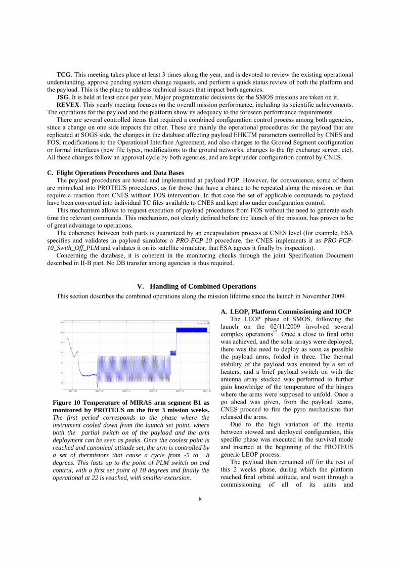
B. ESA FOS Instrument Operational Means The payload MIRAS is on itself a flying entity that implements most of the standard PUS services in ESA
missions. Since it was ESA responsibility its operations and control, the most evident approach was to reuse as much as possible existing ESA infrastructure, as it is reflected in Fig. 8. In this respect, the Mission Control System
(in charge of TC generation and TM monitoring) selected was based on the SCOS-2000. The TM Trend Analysis system, MUST, also ESOC-based, has been enlarged in SMOS to cover also some scientific data.
The MIRAS simulator is a tool that allows end to end validation of MIRAS operations, including a simulation of the CNES SOGS layer. It includes an emulator of the On Board computer, thus allowing to run the real SW. It is also based in an ESA standard SIMSAT environment.
The MIRAS FOP is written and maintained using the ESA MOIS procedure writing tool. Furthermore, it is based remotely at ESOC, in order to allow a combined maintenance with the rest of the other missions.
The only non-ESA standard tool used in the MIRAS operations is the mission planning, being the scientific mission planning not a traditional ESOC activity. It is implemented for SMOS tailoring the Flex Plan generic tool, based in Oracle DB and ILOG rules check.
The operational team at ESAC in routine phase for the payload is composed by 3 persons, that cover the management, HKTM monitor, Mission Planning and ground segment configuration activities. The reuse of a big part of infrastructure allows that other maintenance or recurrent tasks can be handled remotely, with minimum or negligible effort.
This team was augmented with 2 extra persons during the LEOP and IOCP phases of the mission, mainly dealing with Ground Segment SW support and Mission Planning support.
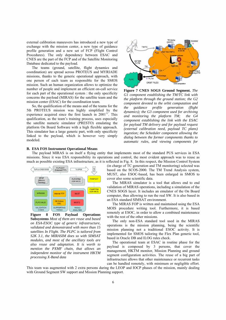
Figure 7 CNES SOGS Ground Segment. The G1 component establishing the TM/TC link with the platform through the ground station; the G2 component devoted to the orbit computation and the guidance profile generation (flight dynamics); the G3 component used for archiving and monitoring the platform TM; the G4 component establishing the link with the ESAC for payload TM delivery and for payload request (external calibration need, payload TC plans) ingestion; the Scheduler component allowing the dialog between the former components thanks to automatic rules, and viewing components for
Figure 8 FOS Payload Operations Subsystems Most of them are reuse and based on ESA-ESOC type of generic infrastructure, validated and demonstrated with more than 15 satellites In Flight. The PLPC is tailored from S2K 3.1, the MIRASIM does so with SIMSAT modules, and most of the ancillary tools are also reuse and adaptation. It is worth to mention the PXMF chain, that allows an independent monitor of the instrument HKTM processing X-Band data

7
It must be noted that the selection of the MIRAS payload operations to be collocated at ESAC together with the DPGS, Quality and Calibration teams, has created a big amount of synergies, and has proven much more effective than a natural colocation with other platform operations. The fact that the Mission Planning is handled from the FOS requires many activities to be coordinated with the scientific teams.
IV. Interfaces This section addresses only the interfaces n the mission among the FOS (Payload Operations) and the SOGS
(Platform Operations at CNES)3.
A. Formal Interfaces The main products exchanged among FOS
and SOGS are the Payload TM and TC and the Mission Planning related files. For design simplicity and considering that payload operations did not require Real-Time TM, al the interchanges are based on files (binary or ASCII), the interchange is based on sftp among servers.
Fig. 9 describes the main exchange of files from CNES to ESA and from ESA to CNES. There is a regular release of S-Band TM and EHKTM telemetry (set of PROTEUS TM useful for the payload provided by CNES after each S-Band pass), typically 4 or 5 times per day. Also, a daily release of orbit files (predicted and restituted), and of the PROTEUS events file containing relevant information for the SPGF Mission Planning to understand platform constraints. Finally, CNES issues an acknowledgement of the received commands and a log of its uplink status.
In turn, ESA generates when required (at least once per week) the commands for the payload. The PLPC system groups them in one or several files, which are placed in the ftp server. CNES fetches this files following explicit instructions from the Payload Operations Team (no automatic commanding is intended, although could be possible). The acceptance and execution reports of the payload commands are provided in the payload TM itself.
Once the SPGF generates the planning for the next week, it generates several products, among them a file to be issued to CNES weekly called the Service Request File, that contains relevant X-Band passes for the payload (those over ESAC) and also the request for maneuvers from the payload side.
The formal interfaces in this process are covered by the OIA, Operational Interface Agreement, a living document that describes the understanding at any given point in the mission of the ESA-CNES combined operations. It performs a functional description of the file interchange (not being on itself an ICD) and the mission planning process and also contains inter-agency agreements regarding management of some pre-defined contingencies, including overall operational constraints and capabilities (on call support, reaction times, and description of the interchanges not based on file exchanges as expected e-mails, phone calls or other document communication).
B. Combined meetings and reviews and System Change mechanism The interagency coordination and activities are managed through set of periodic teleconferences and meetings:
OCG. Weekly teleconference that reviews the status of operations, confirms the go ahead for uplink of the payload mission planning, and reaches agreements for any special operation to happen in the next week. This meeting also addresses platform and payload anomalies.
Figure 9 File exchanges along a day and a week among SOGS and FOS The main inputs from CNES to ESA are the orbital and spacecraft event information, and the S-Band TM. In the opposite direction, ESA provides with TC files for the payload, and also with a Service Request defining the attitude modification needs
8
TCG. This meeting takes place at least 3 times along the year, and is devoted to review the existing operational understanding, approve pending system change requests, and perform a quick status review of both the platform and the payload. This is the place to address technical issues that impact both agencies. JSG. It is held at least once per year. Major programmatic decisions for the SMOS missions are taken on it. REVEX. This yearly meeting focuses on the overall mission performance, including its scientific achievements. The operations for the payload and the platform show its adequacy to the foreseen performance requirements.
There are several controlled items that required a combined configuration control process among both agencies, since a change on one side impacts the other. These are mainly the operational procedures for the payload that are replicated at SOGS side, the changes in the database affecting payload EHKTM parameters controlled by CNES and FOS, modifications to the Operational Interface Agreement, and also changes to the Ground Segment configuration or formal interfaces (new file types, modifications to the ground networks, changes to the ftp exchange server, etc). All these changes follow an approval cycle by both agencies, and are kept under configuration control by CNES.
C. Flight Operations Procedures and Data Bases The payload procedures are tested and implemented at payload FOP. However, for convenience, some of them
are mimicked into PROTEUS procedures, as for those that have a chance to be repeated along the mission, or that require a reaction from CNES without FOS intervention. In that case the set of applicable commands to payload have been converted into individual TC files available to CNES and kept also under configuration control.
This mechanism allows to request execution of payload procedures from FOS without the need to generate each time the relevant commands. This mechanism, not clearly defined before the launch of the mission, has proven to be of great advantage to operations.
The coherency between both parts is guaranteed by an encapsulation process at CNES level (for example, ESA specifies and validates in payload simulator a PRO-FCP-10 procedure, the CNES implements it as PRO-FCP-10_Swith_Off_PLM and validates it on its satellite simulator, that ESA agrees it finally by inspection).
Concerning the database, it is coherent in the monitoring checks through the joint Specification Document described in II-B part. No DB transfer among agencies is thus required.
V. Handling of Combined Operations This section describes the combined operations along the mission lifetime since the launch in November 2009.
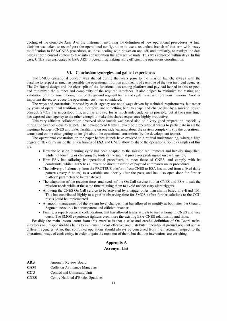
A. LEOP, Platform Commissioning and IOCP The LEOP phase of SMOS, following the
launch on the 02/11/2009 involved several complex operations12. Once a close to final orbit was achieved, and the solar arrays were deployed, there was the need to deploy as soon as possible the payload arms, folded in three. The thermal stability of the payload was ensured by a set of heaters, and a brief payload switch on with the antenna array stocked was performed to further gain knowledge of the temperature of the hinges where the arms were supposed to unfold. Once a go ahead was given, from the payload teams, CNES proceed to fire the pyro mechanisms that released the arms.
Due to the high variation of the inertia between stowed and deployed configuration, this specific phase was executed in the survival mode and inserted at the beginning of the PROTEUS generic LEOP process.
The payload then remained off for the rest of this 2 weeks phase, during which the platform reached final orbital attitude, and went through a commissioning of all of its units and
Figure 10 Temperature of MIRAS arm segment B1 as monitored by PROTEUS on the first 3 mission weeks. The first period corresponds to the phase where the instrument cooled down from the launch set point, where both the partial switch on of the payload and the arm deployment can be seen as peaks. Once the coolest point is reached and canonical attitude set, the arm is controlled by a set of thermistors that cause a cycle from -5 to +8 degrees. This lasts up to the point of PLM switch on and control, with a first set point of 10 degrees and finally the operational at 22 is reached, with smaller excursion.

9
functionalities. This phase involved the collocation at CNES of ESA payload teams, in order to closely follow the deployment of
the arms, and also to assess the thermal situation. The IOCP phase lasted around 6 months for SMOS, and involved the qualification of the payload and also the definition and characterization of its use in routine phase, as well as the identification of the calibration needs for the mission13. In terms of operations, it meant a variable planning (each week the planning criteria were changed), more frequent calibrations, among them more frequent ones involving a maneuver of the platform, some combined characterizations platform/payload to understand radio electric impact of the S Band transmitter or to define the solar array reflection, and finally, a wider use of the payload commanding and several changes to the pre-defined sequences and On Board Operational Procedures. For this phase, also the reaction time and the planning cycle was shortened. At the beginning, it was temporarily enabled the capability for the FOS to place TC’s to be automatically uplinked on the next S-Band pass, even if in not working hours. Also, the planning cycle was shortened to allow to perform planning and re- planning within three days.
B. Routine Phase The SMOS routine phase is characterized by the activities being driven by a fixed and agreed routine calibration
plan on the payload side, and by also a PROTEUS generic routine (daily update of the guidance profile, weekly update of the S-Band downlinks, periodic checks and calibrations of platform units) on the platform side, together with the relevant orbital correction maneuvers to maintain SMOS orbit within given dead bands. The nominal planning cycle is a week, and activities to be conducted are predefined, converted into stacks of time tagged commands (platform or payload level) and uplinked before Thursday on the previous week. Some weeks involve so called External Maneuvers, where the calibration of the instrument is performed in not-canonical attitude, requesting a good coordination between payload programming and platform guidance level.
C. Contingencies and not nominal operations After 2 years in flight, there have been many cases where either anomalies14 On Board or special operations have
required special interactions among FOS and SOGS. The following is a subset of them, selected with the aim to show the combined operational handling of the event more than the root cause of the anomaly itself.
1. CAM
SMOS has been forced to execute 7 Collision Avoidance Maneuvers in 30 months of mission (SMOS orbit is particularly polluted by debris). CAM are identified at CNES side, as a forecast of a possible collision risk of the spacecraft with space debris. Once such an event is identified, the FOS on call support is immediately informed and an avoidance maneuver is planned. No further interaction was foreseen in the original pre-launch operational definition, thus leading that the first such maneuvers created regular science data from the instrument in a not canonical attitude. This was thereafter modified, and currently a CAM alert triggers the execution by CNES of a set of payload procedures in order to ensure that the data out of canonical attitude is flagged so, and also to prevent X-Band transmissions in the period. This approach causes that the mission impact of one of this events is reduced to around half an hour of degraded science data, and avoids the need of mission re-planning afterwards.
2. CCU Reset
A few weeks after instrument switch on, 17/11/2009, it was found that autonomous resets of the instrument computer (CCU) took place, always, but not systematically, at the finalization of X-Band transmissions. This has occurred 19 times in 30 months of mission, and was during the first year of mission the main contributor to data loss and degradation of transmitted data. Following such reset, the instrument losses all its configuration and programming, including the commands stored on its On Board queue that manage the transmissions to ground. Also, the non-transmitted data in the Mass Memory is lost, given the operational concept for SMOS retransmissions.
Figure 11 Distance at equator from the ideal track, in meters. The periodic orbital maintenance corrections can be seen, to ensure a track error of less than 10 Kms. The CAM maneuvers are not noticed, being smaller in size, they tend to be perform to minimize the needs of other corrections. There is an increase in maneuvers along the mission, due to the increase of the solar activity.

10
A dedicated procedure to reconfigure the payload was implemented, and has been updated to reflect the latest understanding of the required settings On Board.
The typical sequence of events for a management of a reset originally was: (1) CCU reset (2) Reception at CNES of the next available S-Band TM (it could go up to 8 hours away) (3) Triggering of the automatic alarm and On Call alert (4) On Call service attending physically to CNES to verify the anomaly (5) FOS being contacted thereafter, and giving the go ahead for recovery (6) Uplink of instrument configuration in the next available S-Band pass (could be up to 8 hours away).
It can be seen that some of the activities were linked to the availability to TM in S-Band, typically gathered 4 or 5 times per day. In turn, the X-Band data is available
every 100 minutes, but no automatic mechanism is available at FOS at nights, and only an operator is available in the DPGS in working hours weekends. A refinement of this strategy led to the capability of the CNES On Call being alerted also from the FOS or DPGS if the CCU reset signature was identified on their side before S-Band data was received. This allowed in several cases to gain hours of science data speeding up the recovery.
Following the SW implementation in October 2011 (that implemented as default mode Full Pol, and started automatically the Local Oscillator calibration upon a reset, thus making the science data meaningful), the reconfiguration of the instrument does not become essential for science data quality, therefore the OIA has been adapted to relax the need of reaction time of the On Call service to the next working hour seven days a week. 3. B1 thermal control anomaly
This is an example of an anomaly that repeated twice along the mission (May 2010 and December/January 2011) that caused the first and only so far triggering of the PROTEUS FDIR in the mission. The Thermal Control (around 22 degrees) of the segments of the instrument arms is performed by the own instrument through a majority vote among a selection of measurement nodes, and setting on or off a heater for each one of the 12 segments in which the instrument is divided. In this case, a failure in the acquisition of the measured temperatures in the node B1 caused the heater to be wrongly switched ON or OFF. A set of PROTEUS thermal nodes are in charge of monitoring externally to the instrument thermal set points for the segments, and are On Board associated with a platform FDIR function to power off the internal heater line in case exceeding a given threshold (45 degrees). This happened on the 04/01/11, leaving therefore this unit in a cool down situation down to the point where its temperature was controlled by a set of safety lines and thermistors.
This has been by far the most impacting anomaly of SMOS, leading to more than 300 hours of degraded data (science is only possible with a stable and comparable thermal setting of all the LICEFs). Several mitigation strategies similar to those implemented in the shorter event in May 2010 were tried. Among them were the power
Figure 12 Time lost in hours due to CCU resets during the SMOS routine mission. It can be clearly noticed the effect of the two operational decisions, specially the modification of the MIRAS OBSW
Figure 13 Sequence of events during the B1 anomaly The figure shows the acquired temperature by PROTEUS of the 3 arm segments of arm B. It can be seen how the B1 segment (in red) changed due to erroneous acquisitions triggering erroneous heater cycles and finally how it lead eventually to an FDIR at 45 degrees, after which equilibrium was reached in the cold side under the control of the survival heaters. After resetting the FDIR the anomaly persisted.
11
cycling of the complete Arm B of the instrument involving the definition of new operational procedures. A final decision was taken to reconfigure the operational configuration to use a redundant branch of that arm with heavy modification to ESA/CNES procedures, as those dealing with power on and off, and similarly, to readapt the data bases at both control centers to take into consideration the new active units. This was achieved within days. In this case, CNES was associated to ESA ARB process, thus making more efficient the operations coordination.
VI. Conclusion: synergies and gained experiences The SMOS operational concept was shaped during the years prior to the mission launch, always with the
baseline to respect as much as possible the operational tradition and means of each one of the two involved agencies. The On Board design and the clear split of the functionalities among platform and payload helped in this respect, and minimized the number and complexity of the required interfaces. It also helped to minimize the testing and validation prior to launch, being most of the ground segment teams and systems reuse of previous missions. Another important driver, to reduce the operational cost, was considered.
The ways and constraints imposed by each agency are not always driven by technical requirements, but rather by years of operational tradition, and therefore, are something hard to shape and change just by a mission design concept. SMOS has understood this, and has allowed for as much independence as possible, but at the same time, has exposed each agency to the other enough to make this shared experience highly productive.
This very efficient collaboration observed since launch was based also on a very good preparation, especially during the year previous to launch. The development teams allowed both operational teams to participate in all the meetings between CNES and ESA, facilitating on one side learning about the system complexity (by the operational teams) and on the other getting an insight about the operational constraints (by the development teams).
The operational constraints on the paper before launch have evolved to a mutual understanding, where a high degree of flexibility inside the given frames of ESA and CNES allow to shape the operations. Some examples of this are:
How the Mission Planning cycle has been adapted to the mission requirements and heavily simplified, while not touching or changing the tools or the internal processes predesigned on each agency.
How ESA has tailoring its operational procedures to meet those of CNES, and comply with its constraints, while CNES has allowed the direct insertion of payload commands on its procedures.
The delivery of telemetry from the PROTEUS platform from CNES to ESA has moved from a fixed daily pattern (every 6 hours) to a variable one shortly after the pass, and has also open door for further platform parameters to be transferred.
The adaptation of the reaction times and needs of the On Call service both at CNES and ESA to suit the mission needs while at the same time relaxing them to avoid unnecessary alert triggers.
Allowing the CNES On Call service to be activated by a trigger other than alarms based in S-Band TM. This has contributed highly to a gain in observing time for SMOS before further solutions to the CCU resets could be implemented.
A smooth management of the system level changes, that has allowed to modify at both sites the Ground Segment networks in a transparent and efficient manner.
Finally, a superb personal collaboration, that has allowed teams at ESA to feel at home in CNES and vice versa. The SMOS experience tightens even more the existing ESA-CNES relationship and links.
Possibly the main lesson learnt from this exercise is that a wise and careful definition of On Board tasks, interfaces and responsibilities helps to implement a cost effective and distributed operational ground segment across different agencies. Also, that combined operations should always be conceived from the maximum respect to the operational ways of each entity, in order to gain the most out of them, but that the interactions are enriching.
Appendix A
Acronym List
ARB Anomaly Review Board CAM Collision Avoidance Maneuver CCU Control and Command Unit
CNES Centre National d’Etudes Spatiales

12
CRF Command Request Form
DPGS Data Processing Ground Segment EHKTM Engineering Housekeeping Telemetry ESA European Space Agency
ESAC European Space Astronomy Centre ESOC European Space Operations Centre FDIR Failure Detection, Identification and Recovery FOP Flight Operations Procedures FOS Flight Operations Segment HKTM House-Keeping Telemetry ICD Interface Control Document IOCP In Orbit Commissioning and Performance JSG Joint Steering Group LEOP Launch and Early Orbit Phase LICEF Lightweight Cost Effective Front-End Receiver MIRAS Microwave Imaging Radiometry using Aperture Synthesis MIRASIM MIRAS Simulator
MM Mass Memory NIR Noise Injection Radiometer NRT Near Real Time
OBOP On Board Operations Procedure OCG Operation Control Group OIA Operational Interface Agreement
PLM Payload Module PLPC Payload Programming Center PROTEUS Plate-forme Reconfigurable pour l'Observation, les Télécommunications Et les Usages
Scientifiques PUS Packet Utilization Standard REVEX Revue d’Exploitation RFI Radio Frequency Interference S2K SCOS-2000
SAA South Atlantic Anomaly SCOS Spacecraft Control Operating System SMOS Soil Moisture and Ocean Salinity
SOGS Spacecraft Operations Ground Segment SPGF SMOS Planning Generation Facility TC, TM Tele-command, Telemetry
TGC Technical Coordination Group
Acknowledgments The authors thank the support from all the colleagues involved in the past and present operations of SMOS,
particularly Juan Piñeiro, Michele Zundo, Massimiliano Mazza, Stephen Cooke, Amparo Garrigues, Roger Oliva, Fernando Martin-Porqueras, Remi Canton, François Bermudo, Didier Pradines, Michel Venet and Michel Le Du.
13
References 1Mecklenburg, S., Drusch, M., Kerr, Y.H., Font, J., Martin-Neira, M., Delwart, S., Buenadicha, G., Reul, N., Daganzo-
Eusebio, E., Oliva, R. and Crapolicchio, R., ESA’s Soil Moisture and Ocean Salinity Mission: Mission Performance and Operations TGARS May 2012, Pg. 1354 – 1366.
2McMullan, K.D.; Brown, M.A.; Martin-Neira, M.; Rits, W.; Ekholm, S.; Marti, J.; Lemanczyk, J.; SMOS: The Payload, IEEE Transactions on Geoscience and Remote Sensing, vol. 46, pp. 594 – 605 (2008).
3Barre, H.M.J.; Duesmann, B.; Kerr, Y.H.; SMOS: The Mission and the System, IEEE Transactions on Geoscience and Remote Sensing, vol. 46, pp. 587 – 593 (2008).
4Martín-Neira, M., Goutoule, J.M., “MIRAS: A two dimensional aperture-synthesis radiometer for soil moisture and ocean salinity observations,” ESA Bull., vol. 92, pp. 95–104, Nov. 1997.
5Corbella, I., Torres, F., Camps, A., Bará, J., Duffo, N.,, and Vallllossera, M., L-band aperture synthesis radiometry: hardware requirements and system performance, International Geoscience and Remote Sensing Symposium, IGARSS 2000, vol. 7. Honolulu (Hw), USA: IEEE, 24-28 July 2000, pp. 2975 – 2977.
6Martín-Neira, M., Corbella, I., Torres, F., Kainulainen, J., Oliva, R., Closa, J., Cabot, F., Castro, A., Barbosa, J., Gutierrez, A., Anterrieu, E., Tenerelli, J., Martín-Porqueras, F. and Buenadicha, G., SMOS Instrument Performance and Calibration, IGARSS 2012
7Lemmetyinen, J., Uusitalo, J., Kainulainen, J., Rautiainen, K., Fabritius, N., Levander, M., Kangas, V., Greus, H., Pihlflyckt, J., Kontu, A., Kemppainen, S., Colliander, A., Hallikainen, M.T., Lahtinen, J.; SMOS Calibration Subsystem, IEEE Transactions on Geoscience and Remote Sensing, vol. 45, pp. 3691 – 3700 (2007).
8Colliander, A., Ruokokoski, L., Suomela, J., Veijola, K., Kettunen, J., Kangas, V., Levander, M., Greus, H., Hallikainen, M., Lahtinen, J., Reference Radiometer of SMOS: Development and Calibration , IGARSS 2006, Geoscience and Remote Sensing Symposium, July 31 2006 - Aug. 4 2006, pp. 3972 – 3975 (2006).
9Martín-Neira, M.; Suess, M.; Kainulainen, J.; Martín-Porqueras, F.; The Flat Target Transformation, IEEE Transactions on Geoscience and Remote Sensing, vol. 46, pp. 613 – 620 (2008).
10Maléchaux, N., Perlik, F., Zaouche, G., Lier, P. “Operations on the new Jason Control Center” SpaceOps 2002, AIAA-2002-T3-31-676
11Sérène, F., Corcoral, N. “Parasol and Calipso : experience feedback of micro and small satellites” SpaceOps 2006, AIAA-2006 5919
12Closa, J., Benito, J., Bergada, M., Borges, A., Cortes, D., Garcia, Q., Olea, A., Lamela, F., Rubiales, P., Sancho, L., Sanz, J.A., Solana, A. and Martin Neira, M., First Assessment of the MIRAS In-Orbit Instrument Verification, ESA Living Planet Symposium 2010
13Martín-Neira, M., Corbella, I., Torres, F., Cabot, F., Closa, J., Kainulainen, J., Castro, R., Barbosa, J., Gutierrez, A., Martín-Porqueras, F., Oliva, R., Anterrieu, E., Brown, M. and McMullan, K., SMOS Payload Performance Assessment, Proceedings of the 2010 IEEE International Geoscience and Remote Sensing Symposium, July 25, 2010, pp. 3150-3153
14Kornberg, M., Buenadicha, G., Closa, J. and Canela., M., SMOS Payload performance maintenance: Impact of anomalies and operational strategies; SPACEOPS Conference 2012.
.