sn standard-ins 0319
TRANSCRIPT

Installation Instructions
www.SimplyNeu.com

2
HOW TO USE THESE INSTRUCTIONS
Thank you for your purchase!Please read each step of this manual thoroughly to ensure proper installation of your new SimplyNeu organizational solution.
These instructions are for informational purposes only. Your wall, any hidden wiring or plumbing, and overall work conditions may not be the same as those shown in the illustrations. It is your responsibility to ensure proper installation and, if in doubt, contact Customer Service. While our products are designed for homeowner installation, you assume all risk associated with the installation process.
These instructions assume that you are installing our standard units (unmodified heights and depths) onto a wall with drywall over standard wood frame or steel stud construction (i.e. 2" x 4" or 2" x 6" framing), or onto a masonry wall. If any aspect of your installation does not apply to these standard construction methods, contact Customer Service (800-218-2493).
Our limited lifetime warranty* is based on following proper installation techniques. Installing your SimplyNeu system in any manner other than the steps outlined in this manual may lead to structural failure of the system.
We want you to be fully satisfied with your purchase. If you discover any parts from your order are damaged, missing or incorrect, please keep all packing material and contact Customer Service at 800-218-2493.
WE APPRECIATE YOUR FEEDBACK We constantly strive to create the best possible experience, and valuable feedback from customers like you helps us understand how we are doing. Please take a few minutes to complete a brief survey and tell us about your experience with our company and products. To complete the survey, visit www.SimplyNeu.com/CustomerSurvey
* For complete warranty information, visit SimplyNeu.com
IMPORTANT HEALTH NOTICE.Some of the building materials used in this home (or these building materials) emit formaldehyde. Eye, nose, and throat irritation, headache, nausea and a variety of asthma-like symptoms, including shortness of breath, have been reported as a result of formaldehyde exposure. Elderly persons and young children, as well as anyone with a history of asthma, allergies, or lung problems, may be at greater risk. Research is continuing on the possible long-term effects of exposure to formaldehyde.
Reduced ventilation may allow formaldehyde and other contaminants to accumulate in the indoor air. High indoor temperatures and humidity raise formaldehyde levels. When a home is to be located in areas subject to extreme summer temperatures, an air-conditioning system can be used to control indoor temperature levels. Other means of controlled mechanical ventilation can be used to reduce levels of formaldehyde and other indoor air contaminants.
If you have any questions regarding the health effects of formaldehyde, consult your doctor or local health department.

3
1. Getting Starteda. Required & Recommended Tools ............................................................4b. Inventory Your Shipment ...........................................................................5c. Installation Overview ..................................................................................6
2. Installation Instructionsa. Wall-mounted System Installation ...........................................................7b. Install Rail for Hanging Vertical Panels .................................................10c. Cam Shelf Installation .............................................................................11d. Recommended Shelf Locations .............................................................12e. Floor-based System Installation .............................................................14f. Installing Toe Kicks ...................................................................................15g. Installing L-Brackets .................................................................................16h. Installing Cleats .........................................................................................17i. Installing Tops ...........................................................................................18
3. Installing Add-onsa. Full-extension Glides.................................................................................19b. Soft-close Glides........................................................................................20c. Drawers .......................................................................................................21d. Baskets ........................................................................................................22e. Slanted Shoe Shelves ...............................................................................23f. Doors ...........................................................................................................24g. Pantry Items ..............................................................................................25h. Laundry Items ............................................................................................26
4. Final Stepsa. Rail Cover ....................................................................................................27b. Hanging Rods ............................................................................................27c. Accessories ................................................................................................28e. Care and Use ..............................................................................................30 5. Vertical Panel Worksheet ......................................................... 31
SECTION GUIDE
SECTION 1: GETTING STARTED Take an inventory of your shipment before beginning installation to ensure your order is complete and correct.
SECTION 2: INSTALLATION INSTRUCTIONSThis section provides detailed instructions for assembling and installing your SimplyNeu system.
SECTION 3: INSTALLING ADD-ONSThis section provides detailed instructions for installing items such as drawers, doors and baskets.
SECTION 4: FINAL STEPSThis section covers installation of rail cover, rods and other finishing steps.

4
REQUIRED AND RECOMMENDED TOOLS
REQUIRED TOOLS:
Drill/Driver
#2 Phillips ScrewdriverLevel
Tape Measure
Hacksaw (28-32 teeth per inch)
HARDWARE INCLUDED PER YOUR ORDER:
Single Cam Screw
2" Rail Screw
Double Cam Screw
Euro Screw
Shelf Pin
E-Z Toggle
Hinge
Adjuster Washer Toe Kick Cam
(#6) 5⁄8" Screw 1" Pin
Drawer Front Screws
1" and 1 ¼" Toe Kick Screws
L-Bracket
2 ¾" Masonry Screw
RECOMMENDED TOOLS (MAY BE HELPFUL FOR SOME INSTALLATIONS):
Square 3/8" Drill BitHammer / Pry Bar /
MalletStep
LadderStud
Finder
Stubby/Offset#2 Phillips
Screwdriver
This unit contains small parts which could be a choking hazard for small children. Children should be under adult supervision at all times or serious injury could occur.

5
INVENTORY YOUR SHIPMENT & REMOVE OLD STORAGE MATERIAL PRIOR TO INSTALLATIONA. CHECK YOUR INVENTORY BEFORE BEGINNING INSTALLATION
1. Check Boxes: Ensure that you have received all boxes in your shipment. Each box is labeled with a company packing label. Note each box as well as the total number of boxes in the shipment.
2. Compare Box Contents to Packing Label: Open each box and compare the contents against the itemized list on the packing label.
3. Organize Material: Organize the material by size and part type.
4. Take an Inventory of the Contents: Take a full inventory. Use the complete parts list or “Order Summary,” as a checklist. If any pieces are damaged, missing or incorrect, please keep all packing material and contact Customer Service at 800-218-2493.
B. REMOVE OLD SHELVING
1. Remove any existing shelving or cabinets.
C. PREPARE WALLS
1. Spackle and Repaint: If desired, fill holes with spackling and repaint wall(s). As you fill in the holes, note these locations, as they often mark the locations of the studs.
p. 1
Name Your Name Here
Invoice Number N1033
CleatQty Description Height Depth Width Color3 Cleat 3 x 24.61 3 3/4 24 5/8 Cognac Cherry1 Cleat 3 x G 3 3/4 27 5/8 Cognac Cherry1 Cleat 3 x 30.63 3 3/4 30 5/8 Cognac Cherry2 Cleat 3 x G 3 3/4 22 1/4 Cognac Cherry
Drawer BoxQty Description Height Depth Width Color3 Drawer Box 8x24x141 Drawer Box 12x24x14
Drawer FrontQty Description Height Depth Width Color1 Drawer 11.22 x 24.49 MD Knob 11 1/4 3/4 24 1/2 Cognac Cherry3 Drawer 7.44 x 24.49 MD Knob 7 7/16 3/4 24 1/2 Cognac Cherry
ShelfQty Description Height Depth Width Color2 Shelf 14 x 29.88 Fix 3/4 14 29 7/8 Cognac Cherry9 Shelf 14 x 23.86 Fix 3/4 14 23 7/8 Cognac Cherry10 Shelf 14 x 23.86 Adj 3/4 14 23 7/8 Cognac Cherry2 Shelf 14 x 26.89 Fix 3/4 14 26 7/8 Cognac Cherry4 Shelf 14 x 21.50 Fix 3/4 14 21 1/2 Cognac Cherry
Vertical - RectangleQty Description Height Depth Width Color2 Vert 14 x 47.40 HDN RH 47 3/8 14 3/4 Cognac Cherry1 Vert 14 x 71.34 HDN RH 71 5/16 14 3/4 Cognac Cherry2 Vert 14 x 47.40 FDN 47 3/8 14 3/4 Cognac Cherry5 Vert 14 x 71.34 FDN 71 5/16 14 3/4 Cognac Cherry
HardwareQty Part Number68 2101726 2103532 AR6-CH16 17007 2101964 210197
DescriptionCam Cover Cognac Cherry Single Cam Screw (12/bag) Oval Rod 1 x S Chrome Oval Rod Ends Zinc Double Cam Screw (6/bag) Shelf Pin (12/bag)
Example of packing label: Example of complete parts list:
IMPORTANT: Checking all of your inventory will ensure that you have all the materials you need before you start. It will help the installation process run smoothly and will help to prevent delays.

6
WALL-MOUNTED INSTALLATIONS 1. Anchor steel rail to wall: The key to installing your system is a well-anchored, level steel rail. Take your time to get this step right, and the rest of the installation will proceed quickly and smoothly. For a summary video showing the rail installation, visit www.SimplyNeu.com/ installation. Note: Since steel rail length is frequently determined by wood stud locations, you must cut the rail with a hack saw. This is usually the only cutting that is required. If you discover steel studs or masonry walls, please call for proper fasteners. Our sturdy systems are designed to support up to 1,200 lbs. per 8 foot section when properly designed and installed. Please follow the rail installation instructions carefully. 2. Hang vertical panels on steel rail: Vertical panels are notched on the rear edge near the top to mate with the angled steel rail. Simply hang the vertical panels on the steel rail in their approximate final locations based on your design.
Note: The vertical panels must be hung directly on the steel rail. Plastic rail cover is provided to conceal any exposed rail after your system has been completely assembled. Occasionally, a vertical panel will be positioned where a rail screw is located. In this case, cut a small amount from the vertical panel to accommodate the screw head. Your hacksaw can be used for this.
FLOOR-BASED INSTALLATIONS
ALL INSTALLATIONS Connect vertical panels and cam shelves with cam locks and cam screws: Cam shelves are semi-permanent. They connect vertical panels and lock in place with cam and bolt hardware. This creates a rigid system frame in which to install adjustable shelves, hanging rods and numerous other components.
INSTALLATION OVERVIEW
Tall, floor-based systems are anchored to the wall by the L-brackets.
Short floor-based systems are anchored to the wall with L-brackets.
7
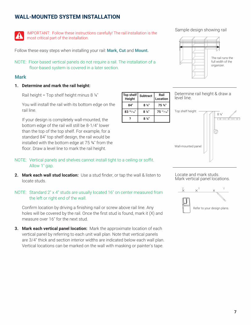
Mark
Follow these easy steps when installing your rail: Mark, Cut and Mount. NOTE: Floor-based vertical panels do not require a rail. The installation of a floor-based system is covered in a later section.
1. Determine and mark the rail height:
Rail height = Top shelf height minus 8 ¼"
You will install the rail with its bottom edge on the rail line.
If your design is completely wall-mounted, the bottom edge of the rail will still be 8-1/4" lower than the top of the top shelf. For example, for a standard 84" top shelf design, the rail would be installed with the bottom edge at 75 ¾" from the floor. Draw a level line to mark the rail height.
NOTE: Vertical panels and shelves cannot install tight to a ceiling or soffit. Allow 1" gap.
2. Mark each wall stud location: Use a stud finder, or tap the wall & listen to locate studs.
NOTE: Standard 2" x 4" studs are usually located 16" on center measured from the left or right end of the wall.
Confirm location by driving a finishing nail or screw above rail line. Any holes will be covered by the rail. Once the first stud is found, mark it (X) and measure over 16" for the next stud.
3. Mark each vertical panel location: Mark the approximate location of each vertical panel by referring to each unit wall plan. Note that vertical panels are 3/4" thick and section interior widths are indicated below each wall plan. Vertical locations can be marked on the wall with masking or painter's tape.
WALL-MOUNTED SYSTEM INSTALLATION
IMPORTANT: Follow these instructions carefully! The rail installation is the most critical part of the installation.
Locate and mark studs.Mark vertical panel locations.
Refer to your design plans.
Sample design showing rail
The rail runs the full width of the organizer.
Determine rail height & draw a level line.
Top shelf height
Wall-mounted panel
8 ¼"
Top shelfHeight
RailLocation
Subtract
84" 8 ¼" 75 ¾"
83 15⁄16" 8 ¼" 75 11⁄16"
? 8 ¼"

8
4. Establish rail lengths: Walk-in spaces generally have some sections that run corner-to-corner and other sections that do not. Some vertical panels may also be “finished” end panels. These aspects of a walk-in space must be considered when establishing rail lengths.
It is strongly recommended that the steel rail ends be anchored to studs, whenever possible. This means running the rail past some end panels.
Finished end panels will require the rail to end ¼" short since the vertical panel notch is not cut completely through the vertical panel.
If your wall is wider than 72", cut two or more pieces of rail so that they meet at a wood stud location. Each piece of rail should be long enough to be anchored into a minimum of two studs for adequate strength. Choose an appropriate stud at which to have two pieces of rail meet. Therefore each piece of rail may need to be cut rather than using any full 72" pieces. The can be cut using a hack saw, a sawzall, or a jig saw.
Subtract ¼" from the rail length for each finished end panel. Finished end panels are not notched completely through.
Establish rail lengths.
Two rail pieces could meet at a stud.
Cut your rail(s) to length using a hacksaw.
Sample plan & rail layout
Rail runs from corner on left to stud on right, and stops short of the Wall B organizer.
Wall A
Wall B
Rail runs from corner to corner. Rail runs from corner on right to stud on left, and stops short of the Wall B organizer.
Wall C
Rail runs from finished end panel less ¼" on right, to stud on left, and stops short of the Wall C organizer.
Finished verticalpanel
Wall D
INSTALL RAIL FOR HANGING VERTICAL PANELS
Cut

9
5. Anchor your rail with screws and E-Z Toggles:
a. Position rail into the correct location. Make sure the bottom of the rail lines up with the hang line and screw into the wall stud that's nearest to the center of the rail.
b. Level the rail and mark a line along the bottom edge.
c. Determine where E-Z Toggles may be needed
E-Z Toggles are required whenever
• a vertical panel is more than 3" from a wood stud or
• a rail end does not coincide with a wood stud location.
Mark the E-Z Toggle locations by holding the rail with the bottom edge on the rail height line on the wall. Mark the wall through the rail holes where E-Z Toggles are required.
Rotate the rail out of position, then install E-Z Toggle anchors as shown in the nearby illustrations.
Rotate the rail back into position. Bolt the rail to the wall using the toggle screws. Ensure the raiL is level when attaching it to the wall.
TIP: Examine a Toggle closely and push a screw into it to understand how it functions.
IMPORTANT: Never use substitutes for our Toggles! Plastic anchors or “Molly Bolts” will not work!
d. Drive black rail screws into available studs at all locations. We recommend two screws per stud where possible. Angle screws if necessary.
IMPORTANT: Do not use substitute toggle hardware! IMPORTANT: Toggles only work with ½" and 5⁄8" thick drywall.
x x
Install E-Z Toggle anchor.
Install E-Z Toggle screw.
Install rail screws.
We recommend two screws per stud, where possible.
Add E-Z Toggles between studs, where required.
Shim rail, if necessary.
Add E-Z Toggles when rail does not end at a stud
Wavy wall
Add shims behind rail to ensure it is straight.
E-Z Toggles at 2" & 5" from rail end
Top View
INSTALL RAIL FOR HANGING VERTICAL PANELS
Mount
IMPORTANT: Failure to shim the rail on a wavy wall will cause the vertical panel notches to break!
IMPORTANT: Do not install rail cover at this time! The rail cover will be installed after vertical panels are hung.
If a vertical panel is more than 3" from the nearest stud, add an E-Z Toggle close to but not under vertical panel.
TAP
Drive anchor into drywall until the flange is flush with the wall surface or slightly countersunk, and arrows point up and down.
Tap screw to deploy clamp. Turn screw 20-25 complete revolutions to tighten. Do not over-tighten or the drywall will be weakened.
E-Z Togglelocation options
Vertical panel
Metal studs? If you indicated that you have metal studs, we would have provided only E-Z Toggles. Avoiding the metal studs, install E-Z Toggles every 6"-8" and two at each rail end as shown nearby.
Masonry Walls? If you indicated that you have masonry walls, we would have provided only 2 3⁄4" masonry screws plus a masonry drill bit. Drill pilot holes at least 1⁄4" deeper than the screw penetration and install masonry screws every 6"-8" and two at each rail end.
6. Make sure the rail is straight: It is important to ensure that the rail is straight. The rail must conform to our shelving system and not to an imperfect wall. Use a long straight edge, such as a 4 foot level or a vertical panel, to locate any hollows or bulges in the wall.
Wherever the wall hollows, loosen the rail screws, insert shims between the rail and the wall and retighten the rail screws. Shims may be any solid, thin material. Another sign indicating that shimming is necessary is if you experience difficulty drawing the cam shelves and vertical panels together later in the installation.

10
23 23 7/8
74 5/8"
24 3/4
23 23 7/8 24 3/4
HANG VERTICAL PANELS
TIP: Install cam screws in top holes before hanging vertical panels. Be sure to use single and double cam screws as indicated. See cam shelf instructions.
Hang notched vertical panels from steel rail, leaving as much space between them as your design plans indicate.
WA
LL
Screwhead
Rail
BrokenNotch
IMPORTANT: If the panel must rest on a screw or bolt head, drill away a small area below the vertical panel notch. A 3/8" drill bit can be used for this. The rail cover will later conceal this modification.
IMPORTANT: Hang vertical panel directly on steel rail, not on rail cover.
CAUTIONS: Do not install rail cover before hanging vertical panels.Do not slide or push vertical panel along steel rail.Do not place vertical panel directly on top of a screw or bolt head. Notch breaks when panel is hung over screw head.
Mark hole location with pencil.
Using a 3/8" drill bit, remove a small amount of material to accomodate screw head.
Place vertical panel onto rail.
A correctly hung vertical panel will be fully seated and close to the wall.
WA
LL
Screwhead
RailPencil
Notch
3/8”Drill bit
Drilled hole toaccomodate
screw head
WA
LL
WA
LL
Screwhead
1 3
2

11
CAM SHELF INSTALLATION (FIXED SHELVES)
Cam shelves are installed with cam and bolt connectors which makes them semi-permanent and creates a more rigid structure.
Some cam shelf locations are exactly determined… by drawers, for example. Other cam shelves may be positioned according to personal needs or preferences.
Recommended locations are made for all of your cam shelf locations.
1. Understand the hardware: Use double cam screws where cam shelves are installed at the same height on the left and right side of a vertical panel. Use single cam screws everywhere else. Do not use single cam screws back-to-back.
2. Installtopcamshelvesfirst:Some designs include connector shelves. Install double cam screws for these.
3. Install cam screws. TIPS: • Use a #2 Phillips bit that is in good condition. • Turn cam screw in slowly to avoid breakage. • Do not spin screwdriver tip in screw head.
4. Place cam shelf onto cam screws.
5. Lockcamfittings: Use a #2 Phillips screwdriver.
6. Layout remaining cam shelf positions: As you continue your installation, some cam shelf positions are exactly determined by the components which will be clearly explained for each component.
For other cam shelves, recommended locations are shown.
¼ - ½ clockwise turn only. Do not force.
IMPORTANT: Hard-to-close gaps between cam shelves and vertical panels indicate that the rail needs to be shimmed straighter. Review rail instructions.
Double cam screwSingle cam screw
Do not use single cam screws directly across from each other.
Install cam screw.
Place cam shelf.
Lock cam fitting.
12
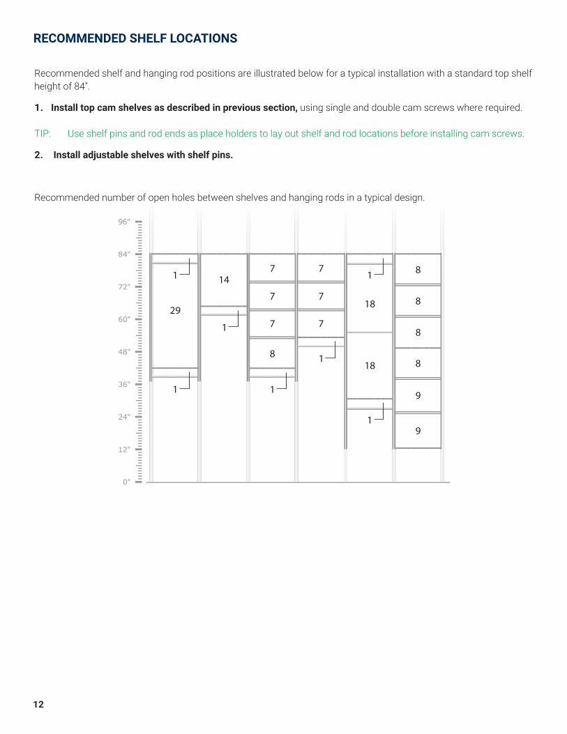
Recommended shelf and hanging rod positions are illustrated below for a typical installation with a standard top shelf height of 84".
1. Install top cam shelves as described in previous section, using single and double cam screws where required.
TIP: Use shelf pins and rod ends as place holders to lay out shelf and rod locations before installing cam screws.
2. Install adjustable shelves with shelf pins.
Recommended number of open holes between shelves and hanging rods in a typical design.
RECOMMENDED SHELF LOCATIONS
29
147
718
18
7
7 8
8
8
8
9
9
7
7
8
1
1
1
1
1
1
1

13
Cam shelves at the top of a stack of drawers are easy to position and install. It just requires a little math and counting.
1. Install the bottom cam shelf according to your design.
a. Wall-mounted system with drawer sections: Position the bottom cam shelf in the bottom-most vertical panel holes.
b. Floor-based system with drawer sections and a toe kick: Position the bottom cam shelf in the 3rd holes up from the bottom of the vertical panel.
2. Use the worksheet here to determine the position of the cam shelf at the top of a stack of drawers.
3. Refer to drawer instructions to complete your drawer sections.
TIP: Use shelf pins as place holders to lay out shelf and drawer glide locations before finally installing screws.
CAM SHELF WORKSHEET EXAMPLE CALCULATION
YOUR CALCULATION
1. Multiply the number of 5" drawers by 4 and enter the value. (Example: For zero - 5" drawers, enter 0x4 = 0)
0
2. Multiply the number of 8" drawers by 6 and enter the value. (Example: For three 8" drawers, enter 3x6 = 18)
18
3. Multiply the number of 12" drawers by 9 and enter the value. (Example: For one 12" drawer, enter 1x9 = 9)
9
4. Add lines 1 thru 3 27
5. Subtract 1 from line 4 -1 -1
6. Number of open holes between cam shelf below drawer(s) and cam shelf above drawer(s) 26
INSTALL CAM SHELVES IN DRAWER SECTIONS
TOE KICK CAM SHELFHEIGHT POSITION
Example:
Zero 5" drawers,three 8" drawers,one 12" drawer.
26 open holesbetween camshelves for this example.
2 ½" 3rd Hole

14
VERTICAL PANELS AND BASEBOARD MOLDINGTo accommodate your baseboard molding, you must either (1) remove it during installation, or (2) cut our vertical panels and possibly bottom cam shelves.
Floor-Based Vertical Panel
Note: We recommend that you remove your baseboard molding if you have floor-based units. After installing your system, reinstall pieces of the molding in any areas not covered by the units.
Cam shelf
Toe kick
Cut panel and shelffor base molding.
The following instructions apply to 84" tall floor-based units, hutch units and mid-height 30" storage units.
Tip: Before beginning, lay cardboard or other protection on your floor, if uncarpeted, near the intended location of your units.
1. Install cam screws in top holes of vertical panels, taking care to use single or double cam screws as called for.
2. Install cam screws for lower/bottom cam shelves according to your design. Follow cam shelf instructions from previous page.
3. Connect cam shelves to a pair of vertical panels, with the parts standing on their back edge.
Note: Install the bottom cam shelf in the 3rd hole from the bottom of the vertical panel.
4. Carefully tip unit into an upright position and move into place.
5. Add remaining cam shelves and vertical panels, if the unit has more than one section.
Tip: Bottom cam shelves can be installed easily by locking the rear cam fittings while the shelf is tilted up like a theater seat. You may need to pull the unit away from the wall slightly to avoid scraping the wall as you lower the front of the shelf. A stubby or offset screwdriver is needed to lock the front cam fittings.
6. Using a level, shim vertical panels, if necessary, to ensure the top is straight and level.
FLOOR-BASED SYSTEM INSTALLATION

15
INSTALLING TOE KICKS
Install toe kicks:
1. Use mallet to pound toe-kick cams into the pre-drilled holes in the toe-kick.
2. Orient the toe-kick so the cam is closer to the top edge.
3. Slide the toe-kicks under the bottom shelf until it snaps onto the cam screws.
1
2
3
CAM
TOE-KICK
ORIENT TOE-KICK SO THE CAM IS CLOSER TO THE TOP EDGE

16
L-brackets are supplied to stabilize or anchor units.
1. Anchor L-brackets to the wall with the appropriate fastener. • Use a 2" drywall screw into a wood stud. • Use a toggle bolt to clamp to drywall when no wood stud is available. • Use a masonry screw to attach to masonry wall.
2. Fasten L-bracket to shelf top with two 5⁄8" screws.
NOTE: Install (1) L-bracket on the top side of the top shelf for all hanging and tall floor-based units. The L-bracket will be installed under the top shelf in a mid-height (30" tall) unit.
INSTALLING L-BRACKETS
A. B. C.

17
INSTALLING CLEATS
All wall-mounted 72" units with a shelf installed in the bottom holes must be cleated for additional support. A cleat is 3" high and the width of the bottom shelf plus ¾". The extra ¾" extends the cleat halfway under each vertical panel.
1. Install unit(s) to be cleated: Install unit(s) to be cleated using the Basic Installation Instructions at the beginning of this manual. Use a level to ensure the sides are plumb.
2. Attach cleat to wall studs: Position the cleat flat against the wall beneath the unit. The cleat must be in contact with the bottom of the vertical panels. Attach cleat to wall studs using rail screws or toggle bolts.
(Steps 3 & 4 are recommended.)
3. Pre-drill holes in bottom cam shelf: Drill 3⁄16" diameter holes near the rear edge through the bottom cam shelf only.
4. Attach unit to cleat: Attach unit to cleat with 2" screws, driving them through pilot holes in cam shelf into cleat.

18
OPTION 1: SCREW THE COUNTERTOP IN PLACE.
1. Drill 3⁄16" diameter holes in the top cam shelves over which the countertop will be placed.
2. Position the countertop and fix in place with clamps, weights or tape, or have a helper hold it.
3. Drive 1 ¼" screws through the cam shelves from beneath into the underside of the countertop or bench top.
CAUTION: Do not drive the screws through the top surface of the countertop.
OPTION 2: ADHERE THE COUNTERTOP TO THE TOP CAM SHELVES WITH CAULKING OR ADHESIVE (WHICH YOU PROVIDE):
IMPORTANT: Follow manufacturer’s instructions on caulk or adhesive product.
1. Lay squiggly lines or dots of caulking or adhesive on the top cam shelves around the perimeter and remaining surface so that no area greater than one square foot is without some caulking or adhesive.
NOTE: It is not necessary to apply large amounts of caulking or adhesive.
2. Position the countertop and fix in place with clamps, weights or tape.
IMPORTANT: Check to ensure that the countertop does not move or slide out of position when clamping, weighting or taping in place.
3. Remove clamps, weights or tape after the caulk or adhesive has set.
Countertops for mid-height storage units may be installed in a variety of ways.
NOTE: The screws will draw the countertop tight to the cam shelves.
INSTALLING TOPS
IMPORTANT: Do not overload unit. If any shelf, top, or bottom of unit bows or bends greater than 1/2", it is overloaded. The shelf, top, or bottom could collapse and cause serious bodily injury and/or damage to personal belongings.

19
INSTALLING ADD-ONS
ATTACH FULL-EXTENSION GLIDESTO VERTICAL PANELSDrawer locations are determined by your design. Follow the guidelines in the nearby illustration to install the cabinet section of the glides, beginning with the glides for the bottom drawer. 1. Glides for the bottom drawer are installed in the 2nd open hole above the cam shelf. 2. Glides for 12" drawers have 8 open holes above before the next set of glides. 3. Glides for 8" drawers have 5 open holes above before the next set of glides. 4. Glides for 5" drawers have 3 open holes above before the next set of glides. 5. Cam shelf above top drawer is installed one hole lower than if it were another set of glides.
Space for5" drawer
Space for5" drawer
Space for8" drawer
Space for12" drawer
Front ofvertical panel
Attach drawer glide cabinet panel sections to vertical panels using Euro screws.
3 open holes
8 open holes
5 open holes
Drawer boxes and drawer fronts are packed separately. Drawer pulls, glides and screws are found in your hardware box. Orders with more than five drawers may have a separate box of glides.
ASSEMBLE DRAWER WITHFULL-EXTENSION GLIDESNOTE: The glides consist of drawer box sections andunit panel sections. Separate them by sliding the plastic lever and pulling apart.
1. Separate the drawer box section by holding the black lever up (1a) and extend out (1b).2. Locate and align. Align the closed end of the drawer box glide flush with the front edge of the drawer box. The side of the drawer box includes dimples to help you align the glide location top to bottom. When the glide is in the proper installation location, the dimples will be visible through the holes in the glide.3. Attach glide to the drawer box using three (3) #6 x 5/8" screws on each side. Install a screw through the glide hole and into the dimple closest to the front of the drawer box first, then into the dimple closest to the back of the box next, and finally into any slide hole near the middle of the box last.4. Drill for the knob using a 5mm or 3/16" drill bit through the countersunk hole located on the back side of the drawer front. Using screw paired with the knob, attach to drawer front tightly though holes.5. SHAKER method for attaching drawer fronts. Pound drawer adjuster inserts flush into shaker front (5a). Using two (2) drawer front screws and washers, attach front to box (5b). Do not fully tighten. Use hand screwdriver only.6. STANDARD method for attaching drawer fronts. Using two (2) drawer front screws, attach front to box. Do not fully tighten. Use hand screwdriver only.
1b
1a
Drawer boxsection
Unit panelsection
PULLFORWARD
PUSHLEVER
2 3
4
5a
5b 6

20
5. SHAKER method for attaching drawer fronts. Pound drawer adjuster inserts flush into shaker front (5a). Using two (2) drawer front screws and washers, attach front to box (5b). Do not fully tighten. Use hand screwdriver only.6. STANDARD method for attaching drawer fronts. Using two (2) drawer front screws, attach front to box. Do not fully tighten. Use hand screwdriver only.
Drawer locations are determined by your design. Follow the guidelines in the nearby illustration to install the cabinet section of the glides, beginning with the glides for the bottom drawer.
• Glides for the bottom drawer are installed in the 2nd open hole above the cam shelf.
• Cam shelf above top drawer is installed one hole lower than if it were another set of glides.
ASSEMBLE DRAWER WITHSOFT-CLOSE GLIDES
1. Install Euro screw into front panel hole. 2. Level or use square to position glide on vertical panel. 3. Use (#6) 5⁄8" screw.
Soft-Close, Full-Extension Glides
ATTACH SOFT-CLOSE GLIDES TO VERTICAL PANELS
Drawer boxes and drawer fronts are packed separately. Drawer pulls, glides and screws are found in your hardware box. Orders with more than five drawers may have a separate box of glides.
NOTE: The glides consist of drawer box sections and cabinet panel sections. Separate them by pushing the plastic lever and pulling apart.
1. Separate the drawer box section by holding the black lever up (1a) and extend out (1b).2. Locate and align. Align the closed end of the drawer box glide flush with the front edge of the drawer box. The side of the drawer box includes dimples to help you align the glide location top to bottom. When the glide is in the proper installation location, the dimples will be visible through the holes in the glide.3. Attach glide to the drawer box using three (3) #6 x 5/8" screws on each side. Install a screw through the glide hole and into the dimple closest to the front of the drawer box first, then into the dimple closest to the back of the box next, and finally into any slide hole near the middle of the box last.4. Drill for the knob using a 5mm or 3/16" drill bit through the countersunk hole located on the back side of the drawer front. Using screw paired with the knob, attach to drawer front tightly though holes.
1b
1a
Drawer boxsection
Unit panelsection
PULLFORWARD
PUSHLEVER
45a
5b
23
6
Space for5" drawer
Space for5" drawer
Space for8" drawer
Space for12" drawer
Front ofvertical panel
Attach drawer glide cabinet panel sections to vertical panels using Euro screws and (#6) 5⁄8" screws.
3 open holes
8 open holes
5 open holes
Vertical Panel
Square
(#6) 5 ⁄8 " screw
Euro screw
1
2
3

21
1
2
DRAWERS
1. To install drawers, move drawers into position so that the glide sections on the drawer box are aligned with the glide sections on the system.
TIP: When installing, you can pull the cabinet glides out to better align the sections.
2. After positioning the drawers, hold them level, and slide them into the system.
NOTE: You will experience some resistance when closing the drawers for the first time. They will operate smoothly afterwards.
ADJUST DRAWER FRONTS
Oversized drawer box mounting holes allow the drawer front to be adjusted upwards, downwards, sideways and even rotated.
Loosen the drawer front adjuster screws from inside the drawer box and adjust the top drawer front so that it is parallel to the top cam shelf. Once aligned, fully tighten the drawer front adjuster screws.
IMPORTANT: Never use a power drill to tighten drawer front screws! Always use a manual screwdriver.
For any drawers below the top drawer, adjust the lower drawer fronts so that the gaps between drawers are uniform across the width of the fronts—approximately 1⁄8".

22
BASKETS
TO ATTACH FULL-EXTENSION GLIDES (STEEL):
1. Thefirststepinattachingyourfull-extensionglidesisdisassembling the glide. To disassemble the glide, first fully extend the glide. Then press the black plastic tab between the arrows with your thumb, and pull the smallest section completely out. (See Figure 1.)
2. Install smaller glide section onto vertical panel with the closed end toward wall. The black release tab is towards the front of the glide section. Set the glide 7⁄8" back from the front of the vertical panel and attach the glide using two Euro screws in the pre-drilled holes.
NOTE: Basket glides are compatible with the pre-drilled holes in 14" vertical panels only. For other depths, you are required to drill at least the rear mounting holes for the basket glides in the vertical panels.
3. Hook glide onto basket. Hook the large glide section onto the basket with the bumper towards the front. (See Figure 2.)
4. Insert basket. Insert basket section into the installed glides on the vertical panels.
ADDITIONAL GUIDELINES FOR BASKETS:
Baskets may be installed according to your preferences with regard to height and spacing. However, we can offer the following guidelines:
A. If a basket is installed just below a cam shelf, allow at least 2 open holes between the basket glide and the cam shelf.
B. If a basket is installed directly over the floor or a cam shelf, 1. allow at least 10 1⁄8" or 7 open holes below the center of glide for an 11" basket 2. allow at least 3 ¾" or 2 open holes below the center of glide for a 6" basket
C. If a basket is installed directly over another basket, 1. allow at least 9 open holes between glides for an 11" basket 2. allow at least 5 open holes between glides for a 6" basket
Figure 1.
Basket Section Vertical Panel Section
PULL
Press black tab and pull apart.
A.
B.
C.
B.
Figure 2.
2nd Rail
1st Rail
2nd Rail

23
TO ATTACH SLANTED SHOE SHELVES:
1. Insert fences into the shelves. Insert the fences into the pre-drilled holes in the front of the slanted shoe shelves.
2. Slanted shoe shelf hardware. The back of the slanted shoe shelf has pre-inserted cams to allow it to lock to the verticals using single cam bolts. These single cam bolts will be screwed into the back holes. The shoe shelf will need to be slanted upward during installation to allow for tightening the back cams. The shoe shelf can then be lowered down, where the front of the shoe shelf will rest on shelf pins.
SLANTED SHOE SHELVES
3. Install bottom shoe shelf. For the lowest slanted shoe shelf, install with the front shelf pins in the 2nd hole from the bottom and the back in the 5th hole from the bottom.
4. Install remaining slanted shoe shelves. Install the slanted shoe shelves with the spacing shown below.
2 open holes above level.
Fence & slanted cam shelf
5 open holes between shelves
Level
Level
Single Cam Screw
Shelf Pin

24
Our doors are half overlay doors with European hinges. All doors are pre-drilled to receive our door hinges. We do not pre-drill for knobs since knob location is based on personal preference.
ASSEMBLING HINGES & INSTALLING DOORS:
1. Assemble hinges: Assemble hinges using Figure 1.
2. Position door plate onto back of door. Make sure that the hinge is square to the edge of the door and not crooked.
3. Use two (#6) 5⁄8" screws to attach.
4. Position the door. Hold door against unit and position it so that the top and bottom cam shelves are partly covered by the door.
5. Attach cabinet plate. Screw the pre-installed hinge screws on the cabinet plate into the closest pre-drilled holes at the front of the vertical panel.
6. Adjustinghinges:The hinges can be adjusted slightly using screws a & b as noted in figure 2.
7. Each door hinge comes with a set of metal hinge covers. The metal hinge covers consist of two pieces that each snap onto the door plate to conceal the installation and adjustment hardware.
DOORS
Pivot top sectiondown and push ontolever to snap together.
Insert notch over hinge pin.
Figure 1.
Figure 2.
Door PlateCabinet Plate
Screw B: Moves hinge left to right along cam shelves.
Screw A: Moves hinge forward and backwards along vertical panel.
1
A B
INSTALLING KNOBS:
Determine door knob locations according to your preference, using other cabinetry in your home as a guide. If you have several knobs to install, consider making a template. Pre-drill the knob hole(s) from the front side of the door using a 5mm or 3⁄16" drill bit. We recommend this drilling direction to avoid the drill bit from chipping out the material on the front side of the door.
TIP: Clamp or hold a scrap board on the back of the door to minimize chip out when the drill bit breaks through.

25
PANTRY ITEMS
WINE RACK: Wine racks are paired with a pre-drilled cam shelf and held in place with 25x5mm pins.
STEMWARE RACK:
Stemware rack attaches to the underside of a shelf.
1. Position stemware rack and mark screw hole locations.
2. Remove rack and drill 1/16" pilot holes on the marks.
CAUTION: Be careful not to drill completely through shelf.
3. Fasten in place using mounting screws provided.
Wine Rack Cradle
Wine Rack Cam Shelf

26
LAUNDRY ITEMS
IRONING BOARD HANGER
Attach ironing board hanger to the vertical panel holes with 2 Euro screws. NOTE: If you are attaching the ironing board hanger to the side of a vertical panel that has no holes, you can drill through 2 holes using a 5mm drill bit on the other side of the vertical panel.
SHELF LINER
The shelf liner simply rests on a cammed or adjustable shelf.
1
2
FrontFront
Front
Back Back
Back

27
FINAL STEPS
RAIL COVER
NOTE: All rail covers are white. The cover is usually concealed by items stored on the shelves and hanging rods, and it is paintable.
1. Cut rail cover to length: Using the interior measurements of each unit, cut the rail cover to length with a hacksaw.
2. Slip cut sections into place: Slip these sections into place over the rail.
VERY IMPORTANT: Never hang vertical panels on top of the rail cover. This will cause the notches to crack.
HANGING RODS
1. Install rod end pairs: Install rod end pairs per design. If the design includes a cam shelf above the hanging rod, leave one open hole between rod end and cam shelf.
2. Insert pre-cut rods into rod ends: The hanging rods are pre-cut ¼" less than the shelf width to allow for the thickness of the rod ends. The fit should be snug, and no screws are required.

28
BELT AND TIE RACKS
1. Extend the Belt/Tie Rack glide. Hold rack at desired height and align the 5th hole from the end of the glide in the back of the vertical panel. Attach using Euro screw.
2. Level the Belt/Tie Rack. Drive a #6 x ½” flat head screw through the front hole of the glide into the vertical panel. Hole in vertical panel is not pre-drilled.
TIP: The Belt/Tie Rack can also be mounted to a wall or door using a different screw.
VALET ROD NOTE: Best placement is within or against a shelf unit at a minimum of 65" from the floor.
1. Mount Valet Rod to vertical panel with four Euro screws.
2. Extend Valet Rod.
1
1
2
2
Belt Rack
Front
Belt Rack
Glide
Euro Screw
#6 x ½" Flat Head Screw
Tie Rack
Back
ACCESSORIES

29
PULL-OUT MIRROR
1. Determine the side of the vertical panel to which you wish to mount the mirror, and ensure that side has 6.5" of clearance from obstruction to allow for installation and proper use.
2. Pull glides back so that the front of the glide is within the black sliding plate.
3. Pivot the sliding plate so that the glides are now perpendicular to the mirror.
4. Pull the glides out until they snap into the fully locked position. You should see two open holes through the black sliding plate.
5. Determine the required top glide height based on the reference chart.
6. Hold mirror up to the vertical panel and align the first open hole in the top glide and mounting plate with the front holes in the vertical panel. Use a Euro screw to attach the glide and mounting plate to the vertical panel.
7. Attach the back of glide with a euro screw through the first oblong hole.
8. Repeat steps 6 & 7 with the bottom glide.
VERTICA
L
ACCESSORIES
Customer Height
Top Glide Height
6' 2" 58"
6' 0" 56"
5' 10" 54"
5' 8" 52"
6.5"
Black Sliding Plate
Two open holes visible through black sliding plate.
The first open hole in the top glide and mounting plate with the front holes in the vertical panel.
Glide
Front
Back Back
Glide
Back of Mirror
6.5"
1"
1
4
5
6 7
2 3

30
CARE AND USE OF YOUR SIMPLYNEU ORGANIZATION SYSTEM
Cleaning Your SimplyNeu System
The surface of your SimplyNeu system can be cleaned by wiping with a damp cloth. If a damp cloth does not adequately clean an area, a non-detergent, nonabrasive household cleaner is recommended. For stubborn stains, use mineral spirits.
Do not use cleaning products containing acetone, acetate or ethyl alcohol. Harsh solvents and/or abrasives such as turpentine may break down the material bonds and should be avoided. Ammonia cleaners should be diluted. Certain waxes may lead to discoloration and are not recommended.
IMPORTANT: Apply solvents to a clean cloth and never directly to the product. Never leave a cloth moistened with solvents on a surface for any length of time.
Adjusting Your SimplyNeu System
Hanging rods, shelves and shoe shelves are adjustable up or down in 1.25 inch increments. Regular shelves rest on pins and can be moved easily. Fixed cam shelves and hanging rods can be moved with a just screwdriver. It’s also simple to move accessories or add them at any time to your organization system after it is installed.
Should you have questions about modifying your organization system after it has been installed, please contact Customer Service at 800-218-2493.

31
VERTICAL PANEL WORKSHEET
The common size vertical panels shown on this page are drawn to scale, including the correct number of 5 mm holes. Use these diagrams to lay out your components and better understand the 32 mm system. Mark the holes where cam screws, drawer & basket glides and rod ends are required. Every fifth hole from the bottom of each panel is marked for your convenience. Print more copies of this worksheet from our online installation manual.
CAM
GLIDE
GLIDE
5"DRAWER
8"DRAWER
12"DRAWER
12 ½"DRAWER
GLIDEGLIDE FOR
12 ½” DRAWER CAM
GLIDE FOR12” DRAWER
GLIDE FOR8” DRAWER
GLIDEGLIDE FOR5” DRAWER
84"
72"
60"
48"
36"
24"
12"
84"
72"
60"
48"
36"
24"
12"
84" HutchVertical Panel
84" StandardVertical Panel
30" Floor Vertical
72" StandardVertical Panel
48" StandardVertical Panel
24" StandardVertical Panel
EXAMPLE PANEL MARKED FOR 4 DRAWERS AND 2 CAM SHELVES(BOTTOM RIGHT OF DIAGRAM)

HAVE ANY QUESTIONS? Give us a call 800-218-2493Monday to Friday: 8:00 AM to 5:00 PM E.S.T.
Se habla Español
IDEAS? COMMENTS?Email to: [email protected]
SimplyNeu130 Central Ave. Holland, MI 49423
www.SimplyNeu.com
© SimplyNeu | ITEM #NSINS | REV. 03/19