snake: an asynchronous pipeline for ultra-low-power
TRANSCRIPT

LETTER
Snake: An asynchronous pipeline for ultra-low-power applications
Zhi-jiu Zhu1,2a), Yi Yu1,2, Xu Bai1,2, Shu-shan Qiao1,2b), and Yong Hei2
Abstract Voltage scaling is an effective technique for ultra-low-powerapplications. However, PVT variation degrades the robust of traditionalsynchronous pipelines severely when voltage scales into the sub-thresholdregion. In this paper, we propose a register-based bundled-data asynchro-nous pipeline that can operate robustly in sub-threshold, called Snake. Bylooping the match delay line, the Snake halves the design overheadcompared to other asynchronous pipelines. We also propose a practicalasynchronous design methodology which is compatible with commercialEDA and needs only a few modifications to synchronous design flow.Monte-Carlo SPICE simulation shows that the pipelined multiplier apply-ing the proposed techniques operates stably in 0.2V and achieves mini-mum power 1.3 nW in 0.2V, minimum energy 1.07 pJ per cycle in 0.3V. Itprovides 6.7 times superiority over synchronous baseline design with 22%area overhead. Comparison with other works in the state of art shows theproposed techniques are quite competitive.Keywords: asynchronous, sub-threshold, ultra-low-power, design meth-odologyClassification: Integrated circuits
1. Introduction
Striding toward the world of IOT and AI, it is indispen-sable to transfer and compute a mass of data, which posesgreat challenges to integrated circuits in terms of perform-ance and energy [1, 2]. In many applications confined bythe battery, energy exceeds performance to become themajor concern in design trade-off. The demand for energyefficiency has motivated designers to scale voltage to thesub-threshold region due to the quadratic relation betweendynamic power and supply voltage [3, 4]. However, alongwith the voltage scaling down to sub-threshold, the circuitdelay degrades severely and become extremely sensitive toprocess, voltage and temperature (PVT) variation, whicheasily leads to timing errors.
The traditional method of sparing timing margin tocover the PVT variation is no longer feasible because of theunacceptable overhead. To deal with the problem, resilientdesign techniques are proposed [4, 5, 6]. Their basicprinciple is to monitor the critical path timing and reactto the timing situation in situ. Once the timing is violated,
it is corrected by error detection logic before error processlogic increases the supply voltage to relieve the workload.However, these synchronous resilient techniques have de-fects in common. First, they are susceptible to metastabilityif data arrives near the clock transition, rather than after[7, 8]. Second, error detection window requires a largenumber of padding in short paths to avoid misdetection,which may introduce more power consumption than saving[6]. Third, error correction usually requires architecturemodification [8]. Last, it requires error detection and cor-rection within one clock cycle in the presence of degradeddelay and slow LDO reaction [9].
Recently, researchers have shown great interest in thepotential of asynchronous circuits being applied for varia-tion tolerance [8, 10, 11]. Different from synchronouscircuits, asynchronous circuits use local clocks to syn-chronize between neighbor registers. The meticulousneighbor handshaking renders the circuits inherently resil-ient, thus more variation-tolerant, energy-efficient andspeed-fast. Nevertheless, asynchronous designs face threemain challenges. First, the design overhead may outbalancethe benefit. Second, asynchronous designs are much morecomplicated, especially the asynchronous timing con-straint. Third, they lack commercial EDA supporting.
In this paper, we present two contributions with respectto the challenges. First, we propose a novel bundled-data[12] asynchronous pipeline for sub-threshold operation,called Snake. It is characterized by a looped request delayline (LRDL), which almost halves the design overheadcompared to other asynchronous pipelines. In addition,the asynchronous pipeline is based on registers rather thanlatches, which simplifies the relative timing constraint(RTC) [13]. Second, we propose a practical design method-ology perfectly compatible with commercial EDA, withonly a few modifications to synchronous flow.
To demonstrate the effectiveness of the proposed tech-niques, we study a case using a 16 � 16 pipelined multi-plier targeting SMIC 55 nm CMOS technology. The post-layout SPICE simulation and Monte-Carlo iterationsshow that the multiplier operates successfully in 0.2V withminimum power 1.3 nW, and achieves minimum energy1.07 pJ per cycle in 0.3V.
The rest of this paper is organized as follows.Section 2 reviews the related work of asynchronous de-signs in sub-threshold and methodology. Section 3 presentsthe proposed Snake pipeline, its RTC, and performance.Section 4 introduces the asynchronous design methodol-ogy. Section 5 shows the experiment results and analysis.Section 6 concludes the paper.
DOI: 10.1587/elex.16.20190293Received May 3, 2019Accepted May 22, 2019Publicized June 4, 2019Copyedited June 25, 2019
1University of Chinese Academy of Science, No. 19(A)Yuquan Road, Shijingshan District, Beijing 100029, China2Institute of Microelectronics of Chinese Academy ofSciences, Beitucheng West Road, Chaoyang District, Beijing100049, Chinaa) [email protected]) [email protected]
IEICE Electronics Express, Vol.16, No.12, 1–6
1
Copyright © 2019 The Institute of Electronics, Information and Communication Engineers
2. Related work
2.1 Asynchronous sub-threshold designIn [10], Chang employs piecewise paralleled delay line ascritical path replica (CPR) to alleviate the variation-inducedmismatch between CPR and logic delay in a bundled-dataasynchronous pipeline. To further decrease performanceand energy penalty due to return-to-zero time in four-phasehandshaking, he substitutes CPR buffers with And-gatetype buffers skewed toward pulling down.
In [11], Liu adapts the MOUSETRAP asynchronouspipeline [14] to sub-threshold operation. He adds an extradelay to the control paths that make the latches opaque,thus widening the capture window and improving theability to capture data delayed by random PVT variation.
In [8], Hand introduces an asynchronous templatecalled Blade, which incorporates error detection conceptfrom synchronous resilient techniques. Variation-inducedviolation is notified to previous and successive stages totrigger the recovery mechanism between neighbor stages.Owing to the meticulous handshaking, metastability andarchitectural modification in synchronous counterpart areavoided.
2.2 Asynchronous methodologyIn general, Asynchronous design methodology can beclassified into two groups [15]. One is to design dedicatedlanguages that best capture the fine-grain concurrency anddistributed synchronization of asynchronous pipelines,along with the synthesis and optimization tools [16, 17,18]. Although it is a more ideal method, it requires redesignusing new languages and conflicts with existing RTLdesigns. Moreover, the readily-available synthesis toolsare at a higher level, leaving little optimization opportunityfor designers. The other is to provide compatibility withexisting synchronous languages and EDA tools. [19, 20,21] redesign asynchronous standard cell (ASTC) librariesin NCL [22] style. After synchronous synthesis, they trans-late the netlists to ASTC. In [23], Cortadella utilizes abundled-data template for the translation, allowing the useof commercial optimized STC. However, he fails to opti-mize the RTC during the synthesis and placement, thus theRTC may not be met.
3. Asynchronous template
This section first introduces the asynchronous control unitand a simple FIFO to exemplify the operation of Snake.Then we present two primitives, JOIN and FORK, toextend the applications in complicated nonlinear pipelines.Last, we elaborate the timing constraint and performance ofSnake.
3.1 Asynchronous FIFOIn a classical bundled-data control unit [12], the requestsignal indicates the arrival of data while the acknowledg-ment signal denotes the success of receiving data. There isa one-sided timing constraint for bundled-data: data mustarrive before request. Therefore, a delay line propagatingthe request is required to match the combinational logic of
data, which is the main overhead of asynchronous tem-plates.
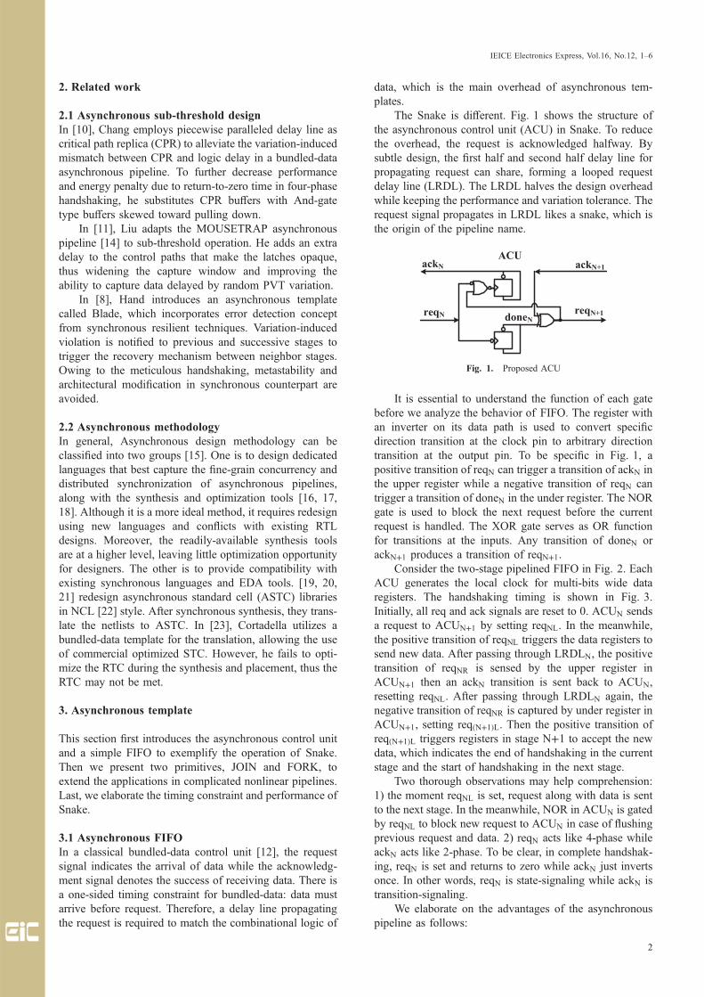
The Snake is different. Fig. 1 shows the structure ofthe asynchronous control unit (ACU) in Snake. To reducethe overhead, the request is acknowledged halfway. Bysubtle design, the first half and second half delay line forpropagating request can share, forming a looped requestdelay line (LRDL). The LRDL halves the design overheadwhile keeping the performance and variation tolerance. Therequest signal propagates in LRDL likes a snake, which isthe origin of the pipeline name.
It is essential to understand the function of each gatebefore we analyze the behavior of FIFO. The register withan inverter on its data path is used to convert specificdirection transition at the clock pin to arbitrary directiontransition at the output pin. To be specific in Fig. 1, apositive transition of reqN can trigger a transition of ackN inthe upper register while a negative transition of reqN cantrigger a transition of doneN in the under register. The NORgate is used to block the next request before the currentrequest is handled. The XOR gate serves as OR functionfor transitions at the inputs. Any transition of doneN orackN+1 produces a transition of reqN+1.
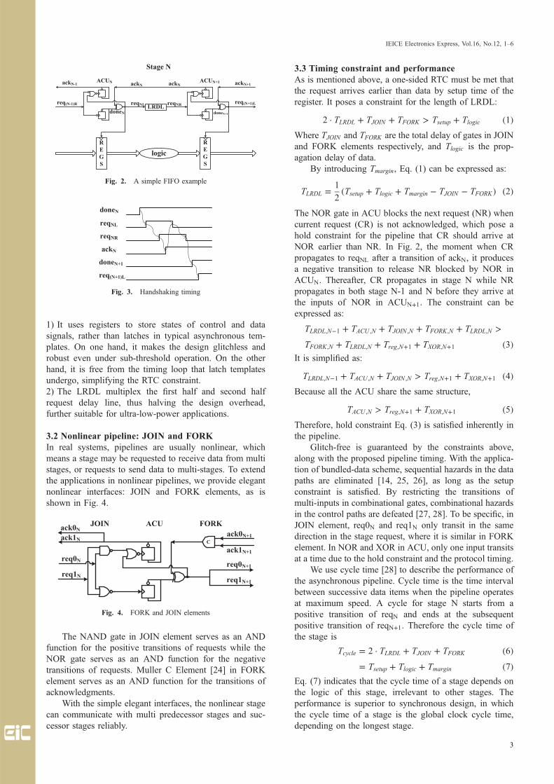
Consider the two-stage pipelined FIFO in Fig. 2. EachACU generates the local clock for multi-bits wide dataregisters. The handshaking timing is shown in Fig. 3.Initially, all req and ack signals are reset to 0. ACUN sendsa request to ACUN+1 by setting reqNL. In the meanwhile,the positive transition of reqNL triggers the data registers tosend new data. After passing through LRDLN, the positivetransition of reqNR is sensed by the upper register inACUN+1 then an ackN transition is sent back to ACUN,resetting reqNL. After passing through LRDLN again, thenegative transition of reqNR is captured by under register inACUN+1, setting reqðN+1ÞL. Then the positive transition ofreqðN+1ÞL triggers registers in stage N+1 to accept the newdata, which indicates the end of handshaking in the currentstage and the start of handshaking in the next stage.
Two thorough observations may help comprehension:1) the moment reqNL is set, request along with data is sentto the next stage. In the meanwhile, NOR in ACUN is gatedby reqNL to block new request to ACUN in case of flushingprevious request and data. 2) reqN acts like 4-phase whileackN acts like 2-phase. To be clear, in complete handshak-ing, reqN is set and returns to zero while ackN just invertsonce. In other words, reqN is state-signaling while ackN istransition-signaling.
We elaborate on the advantages of the asynchronouspipeline as follows:
Fig. 1. Proposed ACU
IEICE Electronics Express, Vol.16, No.12, 1–6
2
1) It uses registers to store states of control and datasignals, rather than latches in typical asynchronous tem-plates. On one hand, it makes the design glitchless androbust even under sub-threshold operation. On the otherhand, it is free from the timing loop that latch templatesundergo, simplifying the RTC constraint.2) The LRDL multiplex the first half and second halfrequest delay line, thus halving the design overhead,further suitable for ultra-low-power applications.
3.2 Nonlinear pipeline: JOIN and FORKIn real systems, pipelines are usually nonlinear, whichmeans a stage may be requested to receive data from multistages, or requests to send data to multi-stages. To extendthe applications in nonlinear pipelines, we provide elegantnonlinear interfaces: JOIN and FORK elements, as isshown in Fig. 4.
The NAND gate in JOIN element serves as an ANDfunction for the positive transitions of requests while theNOR gate serves as an AND function for the negativetransitions of requests. Muller C Element [24] in FORKelement serves as an AND function for the transitions ofacknowledgments.
With the simple elegant interfaces, the nonlinear stagecan communicate with multi predecessor stages and suc-cessor stages reliably.
3.3 Timing constraint and performanceAs is mentioned above, a one-sided RTC must be met thatthe request arrives earlier than data by setup time of theregister. It poses a constraint for the length of LRDL:
2 � TLRDL þ TJOIN þ TFORK > Tsetup þ Tlogic ð1ÞWhere TJOIN and TFORK are the total delay of gates in JOINand FORK elements respectively, and Tlogic is the prop-agation delay of data.
By introducing Tmargin, Eq. (1) can be expressed as:
TLRDL ¼ 1
2ðTsetup þ Tlogic þ Tmargin � TJOIN � TFORKÞ ð2Þ
The NOR gate in ACU blocks the next request (NR) whencurrent request (CR) is not acknowledged, which pose ahold constraint for the pipeline that CR should arrive atNOR earlier than NR. In Fig. 2, the moment when CRpropagates to reqNL after a transition of ackN, it producesa negative transition to release NR blocked by NOR inACUN. Thereafter, CR propagates in stage N while NRpropagates in both stage N-1 and N before they arrive atthe inputs of NOR in ACUN+1. The constraint can beexpressed as:
TLRDL;N�1 þ TACU ;N þ TJOIN ;N þ TFORK;N þ TLRDL;N >
TFORK;N þ TLRDL;N þ Treg;Nþ1 þ TXOR;Nþ1 ð3ÞIt is simplified as:
TLRDL;N�1 þ TACU ;N þ TJOIN ;N > Treg;Nþ1 þ TXOR;Nþ1 ð4ÞBecause all the ACU share the same structure,
TACU ;N > Treg;Nþ1 þ TXOR;Nþ1 ð5ÞTherefore, hold constraint Eq. (3) is satisfied inherently inthe pipeline.
Glitch-free is guaranteed by the constraints above,along with the proposed pipeline timing. With the applica-tion of bundled-data scheme, sequential hazards in the datapaths are eliminated [14, 25, 26], as long as the setupconstraint is satisfied. By restricting the transitions ofmulti-inputs in combinational gates, combinational hazardsin the control paths are defeated [27, 28]. To be specific, inJOIN element, req0N and req1N only transit in the samedirection in the stage request, where it is similar in FORKelement. In NOR and XOR in ACU, only one input transitsat a time due to the hold constraint and the protocol timing.
We use cycle time [28] to describe the performance ofthe asynchronous pipeline. Cycle time is the time intervalbetween successive data items when the pipeline operatesat maximum speed. A cycle for stage N starts from apositive transition of reqN and ends at the subsequentpositive transition of reqN+1. Therefore the cycle time ofthe stage is
Tcycle ¼ 2 � TLRDL þ TJOIN þ TFORK ð6Þ¼ Tsetup þ Tlogic þ Tmargin ð7Þ
Eq. (7) indicates that the cycle time of a stage depends onthe logic of this stage, irrelevant to other stages. Theperformance is superior to synchronous design, in whichthe cycle time of a stage is the global clock cycle time,depending on the longest stage.
Fig. 2. A simple FIFO example
Fig. 3. Handshaking timing
Fig. 4. FORK and JOIN elements
IEICE Electronics Express, Vol.16, No.12, 1–6
3

4. Design methodology
The design flow is automated by Synopsis EDA toolsthrough some homemade TCL scripts. The scripts includeEDA built-in commands for circuit analysis, and commonprogram code for information process, such as set, if,foreach. The flow is shown in Fig. 5.
It starts from a synthesizable RTL design. After syn-thesized to a synchronous netlist, it is imported in Prime-Time (PT) for topology analysis. The needed topologyinformation includes stage critical paths and stage connec-tions. A stage is the abstract terminals of a multi-bits widedata path, represented by multi-bits widen registers in thecircuits. The registers in the same stage are identified bysetting a stage name using built-in command set_user_at-tribute. Stage critical paths are acquired by iterating everypipeline between two stages using built-in command get_timing_paths. By analyzing the startpoins and endpoints ofthe stage critical paths further, we can get the stage con-nection information, which is stored in arrays, a TCL datastructure. For each stage, one array stores its predecessorstages and the other array stores its successor stages.
The netlist is then imported in Verdi for ECO. Byiterating every stage, the clock in netlist is replaced withdistributed asynchronous templates according to the stageconnection information acquired in the topology analysis.In detail, the clock net is removed by built-in command_ecoDeleteConnection. The ACU, JOIN, and FORK areinserted by built-in command _ecoAddInst. The connectionbetween asynchronous units and data registers is done bybuilt-in command _ecoMakeConnection. As an example,the following code shows the ACU insertion and theconnection with stage registers.foreach stage $all_stages {
_ecoAddInst –master ACU –inst ACU_$stageforeach register $stage_registers {
_ecoDeleteConnection –instport $register CK_ecoMakeConnection –instport $register CK
ACU_$stage reqr}
}The raw netlist from ECO does not meet constraint inEq. (1) in the absence of LRDL. Therefore we insert LRDLin the pipeline to optimize the timing in DsignCompiler(DC) by built-in command set_min_delay. The length ofeach LRDL is determined through Eq. (2), with the timinginformation of stage critical paths.
In the back-end, the clock tree synthesis in regular flowis replaced with asynchronous timing optimization, wherethe timing constraint is the same as that in front-end. Apartfrom this, other steps keep the same with regular backendflow.
As can be seen, the proposed design methodology hasthe following merits:
1) It is compatible with existing RTL design. It is crucialbecause commercial designs are based on IP, which doesnot allow designers to modify the design.2) It is compatible with commercial EDA. The added stepsare automated by Synopsis EDA using built-in commands.3) RTC optimization is simple because it is derived fromthe register-based template.
5. Experiment results
We use a 16 � 16 pipelined multiplier as a benchmark toevaluate the proposed techniques. The initial RTL is syn-thesized at 200MHZ, in 1.08V, SS corner, and 125°Ctargeting SMIC 55 nm process. Thereafter, the asynchro-nous design is implemented as a layout through the pro-posed flow. For comparison, a synchronous baseline designis also implemented at the same condition through tradi-tional design flow. Then the layouts are extracted withparasitic RC for accurate SPICE simulation.
We run 100 Monte-Carlo iterations for each supplyvoltage. The results show that the circuit operates robustlyin 0.2V, almost the breakdown voltage of STC. Fig. 6shows the timing diagram for a multiply operation in 0.3V,SS corner and 0°C. Fig. 7 shows the distribution of energyand cycle time over 100 Monte-Carlo iterations in 0.3V.We investigate the energy consumption and performancefurther by operating the pipeline at maximum throughput,fed with the random operands. The performance is eval-uated by cycle time while the energy is evaluated by energyconsumption per cycle or average power consumption overa cycle. Fig. 8 shows the relation of the energy and cycletime with supply voltage. As can be seen, the minimumpower point is 0.2V with 1.3 nW, while the minimumenergy point is 0.3V with 1.07 pJ.
Fig. 5. Design flow
Fig. 6. Simulation waveform in 0.3V, SS corner, 0°C
Fig. 7. Energy and cycle time distribution over 100 Monte-Carloiterations in 0.3V
IEICE Electronics Express, Vol.16, No.12, 1–6
4

Compared to synchronous baseline design, the asyn-chronous design occupies 22% more area, which is ex-pected to be even less if the data width is bigger or theclock distribution in the original design is more compli-cated. As for energy, the proposed technique reduces theenergy, which is 8.24 pJ per cycle in the baseline, by 6.7times. The energy efficiency comes in three ways: 1) thetolerance for variation in sub-threshold supply voltage;2) eliminated unnecessary transitions in clock paths; 3)resilient cycle time for each stage.
The comparison of our work with other state of artis summarized in Table I. It indicates that the proposedtechniques are superior over other works in the state of artin sub-threshold ultra-low-power applications.
6. Conclusion
In this paper, we propose a novel asynchronous pipeline,called Snake, for ultra-low-power applications. The inher-ent resilience of the asynchronous template makes it var-iation-tolerant in sub-threshold. Based on registers ratherthan latches, the template simplifies the timing constraintand makes the design more robust in sub-threshold. Byacknowledging halfway and looping the delay line, thepipeline halves the design overhead. In addition, we pro-pose a practical asynchronous design methodology withonly a few modifications to synchronous flow. It is com-patible with existing RTL design and commercial EDA.Besides, the RTC optimization in the flow is quite simple.
Monte-Carlo SPICE simulation manifests that the mul-tiplier applying the proposed techniques works robustly in0.2V. It achieves minimum power 1.3 nW in 0.2V, andminimum energy 1.07 pJ per cycle in 0.3V at maximumthroughput. Compared to synchronous baseline design, it
decreases energy by 6.7 times with 22% area overhead. It isalso quite competitive compared to other works in the stateof art.
Acknowledgments
This work is supported by National Natural Science Foun-dation of China (61474135).
References
[1] L. Atzori, et al.: “The internet of things: A survey,” Comput. Netw.54 (2010) 2787 (DOI: 10.1016/j.comnet.2010.05.010).
[2] D. Shin, et al.: “DNPU: An energy-efficient deep-learningprocessor with heterogeneous multi-core architecture,” IEEE Micro38 (2018) 85 (DOI: 10.1109/MM.2018.053631145).
[3] L. Lin, et al.: “A 595 pW 14pJ/cycle microcontroller with dual-mode standard cells and self-startup for battery-indifferent distrib-uted sensing,” 2018 IEEE International Solid-State Circuits Con-ference - (ISSCC) (2018) 44 (DOI: 10.1109/ISSCC.2018.8310175).
[4] Y. Zhang, et al.: “8.8 iRazor: 3-transistor current-based errordetection and correction in an ARM Cortex-R4 processor,” 2016IEEE International Solid-State Circuits Conference (ISSCC) (2016)160 (DOI: 10.1109/ISSCC.2016.7417956).
[5] K. Chae and S. Mukhopadhyay: “A dynamic timing errorprevention technique in pipelines with time borrowing and clockstretching,” IEEE Trans. Circuits Syst. I, Reg. Papers 61 (2014) 74(DOI: 10.1109/TCSI.2013.2268272).
[6] S. Kim and M. Seok: “Variation-tolerant, ultra-low-voltage micro-processor with a low-overhead, within-a-cycle in-situ timing-errordetection and correction technique,” IEEE J. Solid-State Circuits50 (2015) 1478 (DOI: 10.1109/JSSC.2015.2418713).
[7] S. Beer, et al.: “Metastability in better-than-worst-case designs,”2014 20th IEEE International Symposium on AsynchronousCircuits and Systems (2014) 101 (DOI: 10.1109/ASYNC.2014.21).
[8] D. Hand, et al.: “Blade – A timing violation resilient asynchronoustemplate,” 2015 21st IEEE International Symposium on Asyn-chronous Circuits and Systems (2015) 21 (DOI: 10.1109/ASYNC.2015.13).
[9] D. Ernst, et al.: “Razor: A low-power pipeline based on circuit-level timing speculation,” 22nd Digital Avionics Systems Confer-ence. Proc. (2003) 7 (DOI: 10.1109/MICRO.2003.1253179).
[10] I. J. Chang, et al.: “Exploring asynchronous design techniques forprocess-tolerant and energy-efficient subthreshold operation,” IEEEJ. Solid-State Circuits 45 (2010) 401 (DOI: 10.1109/JSSC.2009.2036764).
[11] J. Liu, et al.: “Soft MOUSETRAP: A bundled-data asynchronouspipeline scheme tolerant to random variations at ultra-low supplyvoltages,” 2013 IEEE 19th International Symposium on Asyn-chronous Circuits and Systems (2013) 1 (DOI: 10.1109/ASYNC.2013.29).
[12] C. L. Seitz: “System timing,” Introd. VLSI Syst. (1993) http://ai.eecs.umich.edu/people/conway/VLSI/VLSIText/PP-V3/2s/V3.Ch7-2s.PDF.
[13] K. Stevens, et al.: “Relative timing,” Proc. Fifth InternationalSymposium on Advanced Research in Asynchronous Circuits andSystems (1999) 208 (DOI: 10.1109/ASYNC.1999.761535).
[14] M. Singh and S. M. Nowick: “MOUSETRAP: High-speed tran-sition-signaling asynchronous pipelines,” IEEE Trans. Very LargeScale Integr. (VLSI) Syst. 15 (2007) 684 (DOI: 10.1109/TVLSI.2007.898732).
[15] S. M. Nowick and M. Singh: “Asynchronous Design—Part 2:Systems and methodologies,” IEEE Des. Test 32 (2015) 19 (DOI:10.1109/MDAT.2015.2413757).
[16] J. C. Ebergen: “A formal approach to designing delay-insensitivecircuits,” Distrib. Comput. 5 (1991) 107 (DOI: 10.1007/BF02252954).
[17] D. Edwards: “Balsa: An asynchronous hardware synthesis lan-guage,” Comput. J. 45 (2002) 12 (DOI: 10.1093/comjnl/45.1.12).
[18] P. A. Beerel, et al.: “Proteus: An ASIC flow for GHz asynchronous
Fig. 8. Energy and cycle time VS VDD
Table I. Comparison with other works
[29]ISSCC’11
[30]VLSI’17
[31]LSSC’18
[32]JSSC’19
This work
Technology 0.13 um 65 nm 0.18 um 28 nm SOI 55 nm
Architecture8-bit
Multiplier16-bit
Multiplier16-bitFIR
8-bitMAC
16-bitMultiplier
Voltage 84mV 0.8V 0.85V 0.4V 0.3V
Area 0.019mm2 N/A 1.32mm2 2048 um2 0.0441mm2
Cycle time 66 us 2.7 ns 971 us 50 ns 16 us
Power 29.9 nW 1.4mW 99.1 nW 2.2 uW 1.3 nW
Energy 1.97 pJ 3.8 pJ 96 pJ 0.11 pJ 1.07 pJ
IEICE Electronics Express, Vol.16, No.12, 1–6
5
designs,” IEEE Des. Test Comput. 28 (2011) 36 (DOI: 10.1109/MDT.2011.114).
[19] R. B. Reese, et al.: “Uncle - An RTL approach to asynchronousdesign,” 2012 IEEE 18th International Symposium on Asynchro-nous Circuits and Systems (2012) 65 (DOI: 10.1109/ASYNC.2012.14).
[20] M. Moreira, et al.: “Semi-custom NCL design with commercialEDA frameworks: Is it possible?” 2014 20th IEEE InternationalSymposium on Asynchronous Circuits and Systems (2014) 53(DOI: 10.1109/ASYNC.2014.15).
[21] Z. Shin, et al.: “Design of a clockless MSP430 core using mixedasynchronous design flow,” IEICE Electron. Express 14 (2017)20170162 (DOI: 10.1587/elex.14.20170162).
[22] K. M. Fant and S. A. Brandt: “NULL convention logic: A completeand consistent logic for asynchronous digital circuit synthesis,”Proc. of International Conference on Application Specific Systems,Architectures and Processors (1996) 261 (DOI: 10.1109/ASAP.1996.542821).
[23] J. Cortadella, et al.: “Desynchronization: Synthesis of asynchro-nous circuits from synchronous specifications,” IEEE Trans.Comput.-Aided Des. Integr. Circuits Syst. 25 (2006) 1904 (DOI:10.1109/TCAD.2005.860958).
[24] I. E. Sutherland: “Micropipelines,” Commun. ACM 32 (1989) 720(DOI: 10.1145/63526.63532).
[25] S. M. Nowick and M. Singh: “High-performance asynchronouspipelines: An overview,” IEEE Des. Test Comput. 28 (2011) 8(DOI: 10.1109/MDT.2011.71).
[26] S. H. Unger: “Hazards, critical races, and metastability,” IEEETrans. Comput. 44 (1995) 754 (DOI: 10.1109/12.391185).
[27] S. H. Unger: Asynchronous Sequential Switching Circuits (Wiley,New York, NY, 1969).
[28] T. E. Williams: “Self-timed rings and their application to division,”Ph.D Dissertation, Stanford University, Stanford, CA, USA (1991).
[29] N. Lotze and Y. Manoli: “A 62mV 0.13µm CMOS standard-cell-based design technique using Schmitt-trigger logic,” 2011 IEEEInternational Solid-State Circuits Conference (2011) 340 (DOI:10.1109/ISSCC.2011.5746345).
[30] J. P. Cerqueira and M. Seok: “Temporarily fine-grained sleeptechnique for near- and subthreshold parallel architectures,” IEEETrans. Very Large Scale Integr. (VLSI) Syst. 25 (2017) 189 (DOI:10.1109/TVLSI.2016.2576280).
[31] J. P. Cerqueira, et al.: “A fW- and kHz-class feedforward leakageself-suppression logic requiring no external sleep signal to enter theleakage suppression mode,” IEEE Solid-State Circuits Lett. 1(2018) 150 (DOI: 10.1109/LSSC.2018.2883827).
[32] R. Taco, et al.: “An 88-fJ/40-MHz [0.4V]–0.61-pJ/1-GHz [0.9V]dual-mode logic 8 × 8 bit multiplier accumulator with a self-adjustment mechanism in 28-nm FD-SOI,” IEEE J. Solid-StateCircuits 54 (2019) 560 (DOI: 10.1109/JSSC.2018.2882139).
IEICE Electronics Express, Vol.16, No.12, 1–6
6