snohomish county pud #1 · 2018-04-05 · snohomish county pud #1 weatherization specifications...
TRANSCRIPT

1
Snohomish County PUD #1
WEATHERIZATION
SPECIFICATIONS
REVISED
April 2018

2
PUBLIC UTILITY DISTRICT NO. 1 OF SNOHOMISH COUNTY
WEATHERIZATION SPECIFICATIONS
Table of Contents
100.000 GENERAL PROCEDURES................................ 4 .015 Codes........................................ 4 .020 Asbestos .................................... 4 .025 Pre-Installation Inspections................. 4 .030 Customer Contact............................. 5 .035 Materials and Equipment ..................... 5 .040 Workmanship and Warranties................... 5 .045 Use of Premises.............................. 5 .050 Cutting and Patching......................... 6 .055 Protection of Work and Property.............. 6 .060 Post-Installation Procedures................. 6
.070 Insulation R-Value Allowed................... 7 101.000 INSULATION........................................ 8 .100 Material Requirements........................ 8 .200 Installation Requirements for Ceilings under Attic Space.................................. 9 .390 Prescriptive Attic Air Sealing............... 16 .500 Installation Requirements for Underfloor..... 18 .600 Mobile Home Blown in Floor Insulation........ 21 .700 Mobile Home Floor Insulation with No Rodent Barrier...................................... 22 .750 Prescriptive Crawlspace Air Sealing.......... 22 Floor Support Matrix......................... 22
.800 Installation Requirements for Unfinished Walls-Interior............................... 24 .900 Installation Requirements for Walls Blown-In
Insulation .................................. 24 .1000 Duct Sealing and Insulation, Prescriptive.... 26 .1175 Filters...................................... 28 .1180 Combustion Appliance Requirements............ 28 102.000 WINDOWS........................................... 28 .100 General Material Requirements for all
Windows...................................... 28 .145 Sealed Insulating Glass Replacements (Unframed)................................... 28 .150 Replacement Prime Windows (Framed Units)..... 29
.400 Skylights (Glass Glazing).................... 30 .445 Additional Requirements for Skylights........ 31
.500 General Installation Requirements for Window Products..................................... 31 .530 Safety Glass shall be used under the
Following conditions......................... 32 .600 Installation Requirements for Prime Window
Replacements................................. 33 .610 Installations of Replacement Windows with Nailing Flange Removed....................... 33
3
.660 Installations of Replacement Windows with Nailing Flange Intact........................ 35 103.200 SLIDING GLASS DOORS............................... 37 .205 Material Requirements........................ 37 .300 Installation Requirements ................... 38
104.000 INSTALLATION REQUIREMENTS FOR Skylights........... 39 106.000 INSTALLATION REQUIREMENTS FOR HYDRONIC AND WATER PIPE INSULATION................................... 39 GLOSSARY.................................................... 40 INDEX....................................................... 48

4
100 .000 GENERAL REQUIREMENTS
.005 These requirements apply to existing residential (retrofit) weatherization
measures for electrically heated single family 1-4 attached dwellings up to
three stories in height, manufactured homes, and multifamily buildings with
5 or more attached dwellings up to three (3) stories in height. (Individual
Condo units in a five-plex or greater ARE considered multifamily)
.010 Each contractor shall be responsible for informing their installers of the
procedures in this handbook and ensuring the procedures are followed.
100 .015 Codes
Contractors must comply with all applicable state and local codes, HUD
code, and federal regulations as appropriate. When a federal, state or local
code or regulation exceeds the requirements provided here, that code or
regulation applies. If the federal, state or local codes or regulations don’t
exceed these requirements, then these requirements apply. The Utility will
reject any work that is found to be not in compliance with current codes, to
include current state energy codes. This also pertains to any
permits/certifications that may be required for weatherization work to be
performed.
In manufactured homes, all combustion appliances except gas cooking
appliances and gas clothes dryers must be sealed-combustion or have
supply-air ducted from outdoors directly to the appliance. Fireplaces and
wood burning stoves must have tight-fitting glass or metal doors that cover
the entire opening of the firebox.
100 .020 Asbestos
In cases where asbestos materials are found to be present, by the contractor
or anyone in the contractors employ, the contractor shall comply with all
federal, state, and local codes and regulations regarding the handling and
disposal of the asbestos material.
In no case shall the contractor allow anyone in their employ to disturb, in
any way, asbestos materials that are found to be present on the customer’s
property. Asbestos handling and removal shall be performed only by
certified asbestos workers, per current Washington Administrative Code
(WAC).
100 .025 Pre-Installation Inspections
Before any work is started, the contractor shall make a thorough inspection
of the residence and inform the customer of any existing conditions that
would adversely affect the performance of the measures to be installed.
Personal effects stored by the customer in locations that hinder the efficient
application of any weatherization measure must be moved by the customer
before weatherization of that area can commence.

5
100 .030 Customer Contact
All critical measurements, installations and repairs must be made by
prearranged appointment with the customer.
100 .035 Materials and Equipment
Unless otherwise stipulated, the contractor shall furnish all materials, labor,
tools, services, and equipment necessary for the execution and completion
of all work under these specifications.
All materials shall be new, and both workmanship and materials shall be of
good quality.
The Utility reserves the right to identify and disapprove for use in this
program any weatherization product at any time when it deems the product
not satisfactory for the requirements of this program.
100 .040 Workmanship and Warranties
All work shall be done in a workmanlike manner, using craftsmen skilled in
their trades. The contractor shall be prompt and on schedule and complete
work in the time frame agreed upon with the customer.
The installer (against failure due to manufacturing and installation defects)
shall warrant weatherization materials and labor (for both insulation and
windows) for a minimum period of at least two (2) years from the
installation date. Exception: sealed insulated glass units shall be warranted
against failure of the seal for a minimum of ten (10) years. The contractor
must provide a written warranty, including the installation date, to the
Homeowner or Homeowner Designee. Contractors may supply
manufacturers’ printed warranties to satisfy a part of this requirement.
All warranties issued under this Program shall be fully transferable for the
periods stated above.
100 .450 Use of Premises
The contractor shall confine their apparatus, the storage of materials, and the
operations of their workers to limits indicated by law, permits, ordinances,
and/or directions of the customer and shall not unreasonably encumber the
premises with their materials.
100 .050 Cutting and Patching
6
The contractor shall do all cutting, patching, or fitting on the existing
structure that may be required to complete the work in a workmanlike
manner acceptable to the customer and Utility. However, the contractor
shall not endanger the existing structure by cutting or otherwise altering the
structure and shall not cut or alter the structure without the written consent
of the customer.
100 .055 Protection of Work and Property
The contractor shall continuously maintain adequate protection of all their
work from damage and shall protect the customer’s property from injury and
loss arising in connection with their work. They shall make good any such
damage, injury, or loss, except such as may be caused by the customer or
due to causes beyond the contractors control and not to their fault or
negligence.
100 .060 Post-Installation Procedures
The contractor shall keep the premises from accumulation of waste
materials and rubbish caused by their employees or work. At the completion
of the work they shall remove all their rubbish from and about the residence
and all their tools, scaffolding, and surplus materials and shall leave their
work area "broom clean" or its equivalent, unless more exactly specified in
writing.

7
Insulation R-Values allowed under PUD program are as follows:
Home Type Insulation
Observed Existing
Insulation
Post Insulation
Fill Cavity or
Maximum Achievable
Single Family Attic < R-11 R-49
(1-4 dwellings) R-11 to R-19 R-49
Floor < R-11 R-19, 25 or 30
R-11 to R-19 R-30
R-0 closed cavity Minimum R-11
Wall R-0 closed cavity Minimum R-11
Ducts Strip and Seal R-8
Manufactured Floor < R-11 R-22
Home R-11 R-22
Multifamily Attic < R-11 R-49
(5+ dwellings) Floor < R-11 R-30
Wall R-0 closed cavity Minimum R-11
Minimum insulation requirements for exposed walls:
2x4 construction R-13.
2x6 construction R-21.

8
101 .000 INSULATION
This section covers the requirements for the selection of materials,
ventilation, and installation of thermal insulation into existing residences.
.020 Insulation shall be installed in areas of the residence envelope that separate
the conditioned living space from unconditioned or outside space in the
following locations (as specified in this specification where no insulation
exists or the R-value is less than that prescribed in this specification):
.1 Ceilings under attic spaces in permanent housing.
.2 Under floors over unheated spaces in permanent housing.
.3 Unfinished exterior walls in permanent housing bordering living
spaces (exterior garage walls are excluded; garage/house common
walls are included).
.4 Finished exterior walls in permanent housing.
.5 Heating ventilating and air conditioning (HVAC) ducts located in
unconditioned spaces in permanent housing.
101 .100 Material and Installation Requirements
.110 Weatherization contractors must install all measures in a safe, durable, and
effective manner. The following are minimum requirements for selecting
and installing weatherization materials.
.115 Contractors must install all materials according to the manufacturer’s
instructions.
.120 All materials must resist environmental degradation according to how
they’re used and their exposure to environmental factors.
Materials used in weatherization must resist or be;
Corrosion if exposed to corrosive materials.
Mold and rot if exposed to ground moisture or a foundation.
Degradation from ultraviolet light if exposed to ultraviolet light.
Compatible with other elements and materials for the sake of
durability (for example: won’t react chemically).
.125 Structural members and building components must be free of decay and
must be structurally sound before weatherization measures are installed in
their vicinity.
9
.135 The American Society of Heating, Refrigeration, and Air Conditioning
Engineers (ASHRAE) Handbook of Fundamentals is the accepted standard
for R-value/U-factor of materials used by contractors. Products that vary
from ASHRAE are acceptable if they comply with current Federal Trade
Commission (FTC) certifications, testing and labeling rules, and have
independent laboratory testing that indicates the product’s R-value/U-factor.
.140 All insulation materials installed shall meet the requirements of the FTC’s
most current labeling Rules. When unusual conditions exist which indicate
the use of foam plastics, or their combinations with other materials, such
applications shall comply with the IBC, and be approved by the Customer
and the Utility in writing.
.150 The use of insulation materials containing Urea-Formaldehyde is expressly
forbidden on this program.
.155 Duct insulation for use in unconditioned areas on ducts not subject to
routine human contact shall meet the requirements of all current Federal
Specifications. For ducts subject to routine human contact (e.g., in garages,
basements, attics used for storage) the insulation shall also meet all current
requirements, and either be classified as Type 2 or 3, Class A (reflective or
non-reflective, flame rated, faced batts) material or have a covering which
provides physical protection to the insulation and has a flame spread of 25
or less when tested in accordance with the most current ASTM
requirements.
101 .200 Installation Requirements for Ceilings under Attic Space
.210 Insulation shall be installed according to the provisions of the IBC and shall
include the requirements listed below.
.212 Install one insulation depth ruler for every 300 square feet of attic area.
Depth rulers should face the attic entrance.
.220 Ceilings shall be insulated to a minimum of R-49 or the highest R-value
approaching R-49 which is practical, while maintaining the requirements of
this specification.
.230 Attic spaces with floors shall be insulated to the highest practical R-value
approaching R-49.
.240 Knee walls adjoining attic spaces shall be insulated to a minimum of R-13 in
a 2x4 cavity, and R-21 in a 2x6 cavity. If installed, a vapor barrier shall be
installed facing the conditioned, living space. Cover new or existing attic
wall insulation with a durable, vapor-permeable air barrier material to
prevent air penetration of the insulation and to ensure that the insulation is
held in full contact with the wall. Fasten the air-barrier material so that it
10
permanently supports the knee wall insulation.
.245 The installer is responsible for determining that the ceiling system is
structurally adequate to support the combined weight of all materials
imposed on the ceiling structure. Structural damage can be caused by
excessive pressures imposed during installation or by installing insulation in
structures too weak to support the added load. The installer shall be
responsible for ceiling damage incurred during the installation of ceiling
insulation and associated work.
.250 Insulation shall not be installed within 3 inches of the sides nor, when
installed directly over a recessed lighting fixture, within 24 inches of the top
of the recess lighting fixture unless the fixture is labeled for direct cover
(IC) by insulation. A metal, open topped enclosure shall be placed around
recessed lighting fixtures to provide required clearance to the side, and to
prevent loose fill material from blowing into or sloughing onto the fixture.
Such enclosures shall be attached to the ceiling structure to prevent their
displacement during or after application of insulation. Tops of such
enclosures or dams shall extend a minimum of 4 inches vertically above the
final insulation level.
.253 All holes and penetrations through the ceiling (fans, ducting, and recessed
lights) shall be sealed with a non-flammable sealant.
.255 When insulation is to be installed over a heat producing fixture, a solid,
flame resistant, closed-top box shall be used which provides the 3-inch side
clearance and a vertical clearance overhead of at least 24 inches above the
highest point of the fixture. Such enclosures shall be attached to the ceiling
structure to prevent their displacement during or after application of
insulation.
.260 Metal recessed lighting fixtures with enclosed tops may be insulated around
and over without additional protection when certified by an independent
laboratory as being capable of dissipating fixture heat (e.g., UL listed
fixtures will be marked "Recessed Fixture Type IC").
.265 Proper protections are required for all miscellaneous electrical devices (e.g.,
doorbell transformers, ventilating fans, and other motors) in accordance with
current State and local codes.
.270 Insulation shall not be introduced into recessed soffits which contain
lighting, electrical devices (e.g. doorbell transformers, ventilating fans, and
other motors) or flues.
.271 Recessed lighting fixtures and fan/light combinations that are Type-IC rated
by UL may be covered with insulation. Fan/heater, fan/light/heater, and
light/heater combinations may be covered with insulation ONLY IF they
are rated "Heater" or "Air Heater".

11
.272 Ventilation only fans may be covered with insulation. If this method is used
in lieu of baffling, then all holes and penetrations are to be sealed with a
nonflammable sealant. In addition, the fan box must be surrounded with R-
38 unfaced batts and an R-38 unfaced batt placed over the top of the unit.
.273 Only fluorescent fixtures with appropriate thermal protection shall be
covered with insulation.
.275 All insulation materials shall be kept a minimum of 3 inches from all metal
flues. This can be done by installing a solid, non-combustible retaining wall
extending a minimum of 4 inches above the level of loose fill insulation.
.277 All combustible insulation materials shall be kept a minimum of 3 inches
from masonry chimneys. This can be done by installing a solid, non-
combustible retaining wall extending a minimum of 4 inches above the level
of loose fill insulation. Non-combustible insulation may be installed in
contact with masonry chimneys.
.280 Ceiling duct systems (whether supply or return air ducts of a functioning,
circulating air system) shall be stripped of any existing insulation and sealed
with mastic before any additional insulation is applied.
.285 Knob and tube wiring shall be treated with special care. In any case where
installation of insulation is in areas where knob and tube wiring exists, the
following conditions shall be met prior to installing the insulation:
.1 The wiring shall be inspected by an appropriately licensed and
bonded electrical contractor who shall certify that the wiring is in
good condition with no evidence of improper overcurrent protection,
conductor insulation failure or deterioration, and with no improper
connections or splices.
The contractor is responsible for informing the customer of the
requirement to have the knob and tube inspection performed. This
notification must be made to the customer at the time of bid, and
proper arrangements made for payment of the inspection costs
should it be found that the ceiling could not be insulated due to the
condition of the wiring.
.2 Two copies of a knob & tube inspection certificate filled out
completely and signed off by the electrician will be required before
installing the insulation. One copy shall remain attached to the
electrical service panel until the job has been inspected by the
Utility. The other copy shall be sent to the PUD when request for
final inspection is made.
In the event that the insulation is installed prior to the electrical
12
inspection, the contractor shall be liable for the cost of the electrical
inspection as well as any consequential repairs needed to pass the
inspection, or for the costs of removing the installed insulation.
.3 The insulation shall meet Class I specifications as identified in the
IBC, with a flame spread factor of 25 or less as tested in accordance
with current ASTM requirements.
.4 All knob and tube circuits shall have overcurrent protection in
compliance with the most current National Electrical Code.
Overcurrent protection shall be either circuit breakers or Type S
fuses with ampacities no greater than 15 amperes (or as certified as a
safe ampacity, on the inspection certificate signed by the inspecting
electrician.)
.290 Provided all of the above conditions are met, insulation may be installed
directly around and over wiring to the desired level. If batts are used they
shall be unfaced. However, a more stringent local or state code may
preclude the use of the above method. It is highly advisable that the
contractor checks with the jurisdictions in his service areas to insure that the
appropriate codes are adhered to.
.295 Attic entry access openings shall be framed to prevent loose fill insulation
from falling or sloughing through the opening. Alternately, a 14 inch or
wider insulation batt, with an R-value equal to that specified for the attic,
may be placed around the perimeter of the attic access opening to contain
the loose fill insulation.
.300 Attic access doors that open to a heated space shall be insulated to the same
R-value as the attic insulation for horizontal openings, and to at least R-13
for vertical openings.
.305 Access doors (in heated spaces) which incorporate retractable ladders or
similar devices are required to be insulated by installing an insulated cover
(minimum R-30) over the opening in the attic. Insulation shall be secured so
that operation of the retractable ladder will not disturb the insulation.
.310 Attic access doors shall be weather-stripped with appropriate materials if
they open to a heated, living space. Horizontal openings require felt or foam
backed, self-adhering tape. Vertical openings require door weather-
stripping.
.312 Water pipe insulation shall be part of attic insulation. After installation a
minimum of R-3 shall be present on any water pipes, not enclosed within
the attic insulation. The insulation shall be permanently attached to the pipe
with wire, cable ties or twine wrapped around the insulation (support
13
method shall not compress the insulation to less than R-3). Water pipes that
are protected by (enclosed within) installed attic insulation are not required
to be separately wrapped. Pre-formed material specifically designed for
water pipes shall have a flame spread rating of 25 or less when tested in
accordance with the most current ASTM standards. If fiberglass batts are
used, then the batts shall be at least R-7 when flat.
.313 All water shut off valves that are covered by attic insulation shall be so
identified using a method that allows the valve to be readily located by the
customer.
.315 Exhaust fans {except kitchen range exhaust fans (see 101.320)} that vent
any living space directly into the attic space (or to an unsealed vent cap)
shall be extended through to the outside and shall be mechanically attached
to a vent cap. Attachment to the vent cap shall be substantially airtight.
Tape shall not be acceptable for use as a fastener.
Extension material shall be made of metal, be mounted in a secure manner,
and of appropriate diameter for the vent opening. Its configuration shall be
such that no traps or reversing horizontal runs are present. Plastic/vinyl flex
duct shall not be used. If plastic or vinyl flex duct is evident on an existing
exhaust fan, it shall be replaced with metal or HVAC flex-duct and insulated
to a minimum of R-4. Dampered vent caps shall be installed on fans not
containing dampers as part of the housing. Exhaust fans assemblies shall
have only 1 damper per unit (either in the fan unit itself or in the vent cap).
There shall be no more than a 2 foot horizontal run in ducting. The exhaust
cap shall not terminate within two feet of any attic intake or exhaust vent.
.320 Kitchen hood range exhaust fans shall be connected to a rigid duct of not
less than 28 gauge galvanized steel which is substantially airtight throughout
and which terminates directly to the outside in a metal vent cap with no
more than a 2 foot horizontal run. Combustible insulation must be kept a
minimum of 2 inches from the duct (baffled). There shall be one damper per
unit, either in the fan hood unit itself or in the metal vent cap. Exposed duct
runs shall be wrapped with insulation at least R4 in value. The exhaust cap
shall not terminate within two feet of any attic intake of exhaust vent.
.325 If clothes dryers are found to be vented directly into the attic space, ceiling
insulation shall not be installed until the vent is extended directly to the
outside of the structure. The vent ducting shall not exceed 25 feet and shall
terminate in a non-screened vent cap with a damper. Extension material in
excess of 6 feet must be metal with a non-ribbed interior and must be
mounted in such fashion that no traps or reversing horizontal runs are
present. Clothes dryer vent caps shall not be screened. Ducting shall be
insulated to at least an R-4 in value. The exhaust cap shall not terminate
within two feet of any attic intake or exhaust vent.
14
.330 If a vapor barrier is installed with ceiling insulation, it must be placed next
to the ceiling (between the insulation material and the conditioned, living
space). Existing vapor barriers within the first 1/3 of the final R-Value
(depth) are acceptable. A vapor barrier shall not be installed over the top of
existing insulation. Slashing of existing or added vapor barriers shall not
be allowed.
.335 The total net free ventilating area in attic spaces shall be determined to meet
the following requirements or shall be modified to meet these requirements
as an integral part of any ceiling insulation installation. Where adequate
ventilation cannot be obtained, ceiling insulation shall not be installed.
.1 Enclosed attics shall have cross ventilation (over the top of all
insulation) for each separate space provided by ventilating openings
protected against the entrance of rain and snow. The total net free
ventilating area of these openings shall be 1 square foot per 150
square feet of attic area (1:150). If there is a 3-foot vertical distance
from low to high vents, or if a vapor barrier is present, venting can
be reduced to 1 square foot (net free area) per 300 square feet of attic
area (1:300). In either case, 50-60% of the ventilation shall be
installed as exhaust (high) and 40-50% shall be installed as intake
(low).
Alternative vent placement requests must be submitted to the
appropriate Utility inspector in writing. If approved, approval by the
Utility will be issued in writing and must be in hand prior to the
installation of any alternate means of ventilation. Any alternative
venting requests will be on a case by case basis.
.2 Net free ventilating areas is the net effective area of a ventilator after
adjusting for its gross ventilating area. Screens and/or louvers can
reduce net free area by as much as two-thirds. To determine the net
free ventilating area of a vent, divide the gross ventilating area of the
ventilator by the Area Factor in the following table:
Covering Area Factor 1/4 inch hardware cloth 1.0
1/4 inch hardware cloth w/rain louvers 2.0
#8 mesh screen 1.25
#8 mesh screen w/rain louvers 2.25
#16 mesh screen 2.0
#16 mesh screen w/rain louvers 3.0
Rain louvers only 2.0
.3 Roof vents shall be installed with sufficient spacing between the
vents to prevent localized circulation or short-circuiting of
ventilation.
15
.4 Roof Jacks shall not be used to provide intake (low) ventilation
unless the situation has been evaluated and low roof jack installation
has been approved, in writing, by the Utility.
.340 Eave or soffit vents alone shall not be considered as providing adequate
“cross ventilation." Additional means of establishing ventilation by natural
convection shall be incorporated.
.345 Ventilation baffling shall be provided so that at least two and one half (2 ½)
inches measured perpendicular to the sheathing over the full joist/truss
spacing is available for incoming air from the soffit or eave openings. A
shorter distance may be used if the opening defined by the baffle, sheathing,
and joist/trusses has a net free ventilating area equal to or greater than the
net free ventilating area of the soffit or eave openings.
.350 Ventilation baffles shall be of weather-resistant cardboard, or other
approved materials. Mineral wool batts of sufficient thickness to adequately
baffle, and yet maintain the free air clearances are acceptable. All baffles
must extend out over the wall top plate. Baffles shall be visible above the
final insulation level. Face stapling of baffles is not allowed.
.355 All soffit or eave openings shall be left free of any blockage by insulation or
other materials, and such eave systems must remain effective following
weatherization.
.360 Sloping ceilings shall be ventilated by maintaining a minimum space of one
(1) inch between the top of any insulation material and the bottom of the
roof sheathing. Cross ventilation shall be provided by openings at the top
and bottom of the space.
.365 Air turbines shall not be installed on a residence to provide for required
ventilation. Ventilation provided by existing air turbines may be included
by calculating the net free ventilating area of the air turbine in a locked
(non-rotating) position.
.370 If ventilation for the attic is supplied through an attached garage. Then the
net free ventilating area supplied through the garage shall be considered the
smallest of either the ventilating area between the attic space and garage
(attic opening) or the ventilating area between the garage and the exterior
(outside). In this situation, the calculation for the total ceiling area to be
ventilated shall include the garage floor area
.385 Upon completion of the insulation of the ceiling, one empty bag or the
wrapper of the insulation material used shall be left in a convenient location
near the access opening in the attic.
16
Upon completion of insulating the ceiling, two insulation certificates shall
be completely filled out by the installer. One shall be attached to the interior
of the attic space in a convenient location nearby and visible from the attic
access opening. The other shall be mailed to the UTILITY along with other
inspection request papers.
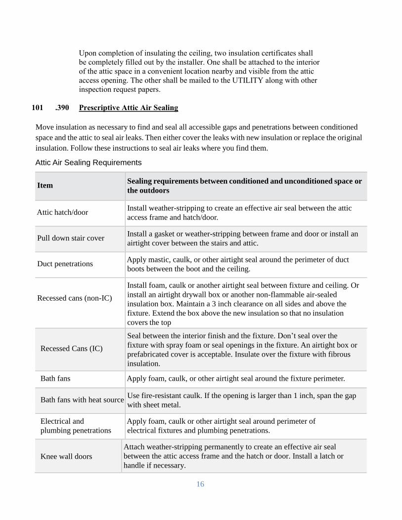
101 .390 Prescriptive Attic Air Sealing
Move insulation as necessary to find and seal all accessible gaps and penetrations between conditioned
space and the attic to seal air leaks. Then either cover the leaks with new insulation or replace the original
insulation. Follow these instructions to seal air leaks where you find them.
Attic Air Sealing Requirements
Item
Sealing requirements between conditioned and unconditioned space or
the outdoors
Attic hatch/door
Install weather-stripping to create an effective air seal between the attic
access frame and hatch/door.
Pull down stair cover
Install a gasket or weather-stripping between frame and door or install an
airtight cover between the stairs and attic.
Duct penetrations
Apply mastic, caulk, or other airtight seal around the perimeter of duct
boots between the boot and the ceiling.
Recessed cans (non-IC)
Install foam, caulk or another airtight seal between fixture and ceiling. Or
install an airtight drywall box or another non-flammable air-sealed
insulation box. Maintain a 3 inch clearance on all sides and above the
fixture. Extend the box above the new insulation so that no insulation
covers the top Recessed Cans (IC)
Seal between the interior finish and the fixture. Don’t seal over the
fixture with spray foam or seal openings in the fixture. An airtight box or
prefabricated cover is acceptable. Insulate over the fixture with fibrous
insulation.
Bath fans Apply foam, caulk, or other airtight seal around the fixture perimeter.
Bath fans with heat source
Use fire-resistant caulk. If the opening is larger than 1 inch, span the gap
with sheet metal.
Electrical and
plumbing penetrations
Apply foam, caulk or other airtight seal around perimeter of
electrical fixtures and plumbing penetrations.
Knee wall doors
Attach weather-stripping permanently to create an effective air seal
between the attic access frame and the hatch or door. Install a latch or
handle if necessary.
17
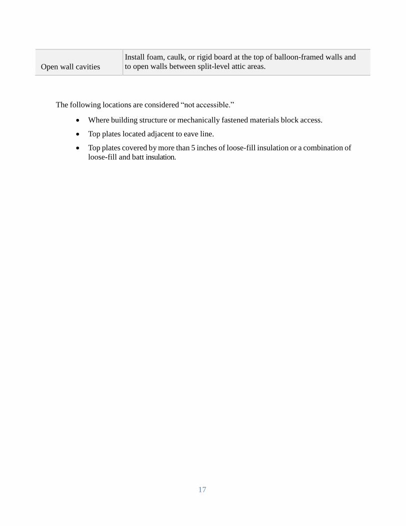
Open wall cavities
Install foam, caulk, or rigid board at the top of balloon-framed walls and
to open walls between split-level attic areas.
The following locations are considered “not accessible.”
Where building structure or mechanically fastened materials block access.
Top plates located adjacent to eave line.
Top plates covered by more than 5 inches of loose-fill insulation or a combination of
loose-fill and batt insulation.
18
101 .500 Installation Requirements for Under Floors
.505 Insulation shall be installed according to the IBC and shall include the
requirements listed below.
.510 Floor insulation shall be a minimum of R-30 or fill the joist cavity fully. The
insulation shall be installed in substantial contact with the under floor.
.515 If any indication of fungal decay, or insect infestation is found before or during
installation of underfloor insulation, appropriate action shall be taken at the
homeowner’s expense before any further installation of insulation is done.
.520 If any wet areas of the subfloor or wood supporting members are found, then the
source of the moisture shall be eliminated and wet areas dried out at the
customer’s expense before floor insulation is installed.
.525 Crawl space ventilation shall be 1:150 Net Free area unless the crawl space is dry,
in which case 1:300 is acceptable. Place vents as close to corners as practical,
with balance evenly distributed along the walls. Place vents on opposing walls
for cross ventilation. Where adequate ventilation cannot be obtained, the
contractor shall contact the Utility (inspector) for approval prior to installing
any insulation. The presence of a sump pump will constitute a wet crawl.
.527 All newly installed crawlspace vents shall be covered with 1/4 inch mesh. All
added crawl space vents shall provide at least 50 square inches and not more than
144 square inches of net free area. Louvered vents designed for use in soffits (or
similar vents) shall not be used as crawl space ventilation except when requested
by the customer and approved in writing by the Utility.
.530 A ground cover moisture barrier shall be in place upon job completion. The new
ground cover shall be 6 mil black polyethylene and all joints shall be overlapped
with sufficient material so that all ground surface area is covered. Ground cover
shall not contact wood members of the structure.
.535 If underfloor insulation is installed over an unheated basement and the basement
has no exposed soil then the provisions for a ground cover and ventilation are not
required. Any basement with exposed soil shall be treated as a crawl space and
the provisions for ventilation shall be required. In addition, a ground cover shall
be present which covers the entire area of exposed soil.
.540 If clothes dryers (or other exhaust systems) are found vented directly into the
crawl space, underfloor insulation shall not be installed until the vent is extended
directly to the outside of the structure. The vent shall terminate in a non-screened
vent cap with a damper and ducting shall not exceed 25 feet. Extension material
in excess of six feet must be metal with a non-ribbed interior and mounted in such
fashion that no traps or reversing horizontal runs are present. All exposed ducts
shall be insulated to an R-4. The dryer exhaust shall not terminate within two feet
of any existing crawlspace vents so chances of moisture from exhaust getting
19
back into crawlspace are minimized.
.543 Kitchen range exhaust fans that are vented to the crawl space shall be ducted
through to the exterior of the building in accordance with local codes and the
manufacturer’s instructions. (See spec 101.320) Kitchen exhaust ducts shall not
terminate within two feet of any existing crawlspace vent.
.545 Support of floor insulation shall be provided in accordance with the floor matrix
shown in the chart on the following page. Batt insulation encapsulated with a
poly-wrap system may be installed by stapling through the triple reinforced
flanges. Additional support is not required with the use of this product.
.550 Support systems for floor insulation shall not compress the insulation material
more than 10 percent or otherwise alter the insulation value of the material except
where necessary around the perimeter. Support systems will be allowed to
compress floor insulation greater than 10 percent in those cases where an
insulation batt of greater R-value is used to fill a joist cavity which requires a batt
of lesser R-value (i.e. installation of an R-30 batt in place of R-25 in a 2 x 8 joist
cavity).
.551 Support of insulation shall be provided within 3 inches of the end of each batt.
.555 Vapor barriers, when installed, shall have a perm rating of 1.0 or less and shall be
located between the insulation material and the conditioned, living space.
.560 Crawlspace access openings must be provided by the customer. Any access door
adjacent to a conditioned space shall be insulated to the same R-value as the floor
insulation for horizontal openings and to at least R-13 for vertical openings.
.565 Crawlspace access doors that are adjacent to a conditioned space shall be weather-
stripped with appropriate materials.
.570 Crawlspaces must be properly enclosed to prevent entry of animals that may
damage the insulation. Exterior access doors shall be installed in such a manner
so as to prevent entry by animals. If new wood material is required to be added,
then it shall consist of treated materials.
.575 Water pipe insulation shall be part of underfloor insulation. After installation a
minimum of R-3 shall be present on any water pipes, including piping for
refrigerator ice makers not enclosed within the floor insulation. The insulation
shall be permanently attached to the pipe with wire, cable ties, twine, strapping
tape, or other Utility approved methods. Waste or drainpipes are excluded from
this insulation requirement. Water pipes that are protected by (enclosed within)
installed floor insulation are not required to be separately wrapped. Pre-formed
material specifically designed for water pipes shall have a flame spread rating of
25 or less when tested in accordance with the most current ASTM standards. If
fiberglass batts are used, then the batts shall be at least R-7 when flat.
.580 All water shut off valves that are covered by floor insulation shall be identified
with attached tags that hang below the insulation.
20
.590 Underfloor insulation in areas which are exposed to environmental elements
(wind, rain, etc.) shall be protected after installation with a breathable cover or
some type of perimeter system (e.g. skirting).
.591 Foam insulations must meet thermal and ignition barrier requirements for “foam
plastics,” as detailed by the local building code and enforced by local building
officials. Spray foam insulation typically needs no support. When installing
fiberglass batts or blown fiberglass underneath foam, as additional floor insulation
or as an ignition barrier, support the fiberglass insulation.
.595 Enclosed floor cavities, such as a finished ceiling over a garage may be insulated
by drilling holes a minimum of one (1) inch in diameter for cellulose, or (2)
inches for mineral wool into the floor cavity between the joists from the underside
of the floor and blowing the cavities full. When the cavities are blown full, and
after an in-progress inspection has been made, plug and spackle the holes.
Insulation shall not be blown more than 3 feet in any direction unless the insert
tube method is used.
.597 When insulating open floors above garages or unheated basements, follow
standard support methods. An alternative temporary support system may be used
provided the customer agrees, in writing, to cover the insulation with sheetrock or
in accordance with local codes.
.598 Underfloor areas insulated with fiberglass batts subject to routine human contact
shall be covered with a breathable material that inhibits the movement of
insulation particles but allows water vapor to pass through. The material must
have a flame spread rating of 25 or less as tested in accordance with the most
current ASTM standards.
101. .600 Mobile Home Blown In floor Insulation
.605 Obtain any permits required by the Department of Labor, City or County that may
be necessary to work on mobile home.
.610 Inspect underfloor for leaks, rot or pest infestation. If any problems exist, repairs
shall be made prior to beginning any weatherization work is started.
.615 The skirting on the mobile home shall be continuous around the home without
gaps. If gaps exist, repairs shall be made.
.620 For insulation installed through an existing rodent barrier, there shall be access
holes drilled for every joist run. The first hole shall be made within 3 feet of the
exterior edge of the mobile home. The holes shall be spaced no more than 72
inches (6 feet) apart. On double wide mobile homes the center beam shall also be
considered as an exterior edge.
.625 Each cavity shall be filled using a 90 degree directional nozzle.
21
.630 All insulation access holes shall be patched and sealed with a material of
sufficient strength to insure it will not tear, come loose, or create an easy access
for rodents.
.635 A 6 mil ground cover shall be installed under homes where none exists or the
existing is damaged beyond repair. The ground cover shall cover the entire area
under the home including all structures connected to the mobile home and open to
the crawlspace (e.g. enclosed porches, laundry room add-ons).
.640 The crawlspace shall be vented at a ratio of 1 square foot of ventilation for every
150 square feet of floor area if wet. If dry than 1 square foot for every 300 s/f.
When calculating the required ventilation, include all enclosed areas that open into
the crawlspace (e.g. porches and any other add-ons).
.645 Water pipes exposed below the level of the rodent shall be wrapped with
insulation with an R-value of at least R-3.
.650 If clothes dryers (or other exhaust systems) are found vented directly into the
crawlspace they shall be extended out of crawlspace in accordance with
specification #101.540 & 101.543.
.655 A certificate of insulation shall be provided to both homeowner & PUD.
101 .700 Mobile floor Installation with missing Rodent Barrier
.705 In applications where the rodent barrier is removed or is damaged beyond
reasonable repair, the contractor shall install batt insulation.
.710 The batts shall be installed using any of the methods allowed under the floor
installation methods under specification 101.500.
.715 All applicable areas of the Weatherization specifications shall be adhered to,
including floor support, heating ducts, exhaust ducts, water pipes, ground cover
and venting.
.720 The contractor shall inform the homeowner, prior to insulating, that a rodent
barrier cover is required by Labor & Industries.
.725 A certificate of insulation shall be provided to both homeowner & PUD.
101 .750 Prescriptive Crawlspace Air Sealing
.755 Comply with the following table when performing air sealing in a crawlspace.
Crawlspace Air Sealing Requirements

22
Item
Sealing requirements between conditioned space and unconditioned
space or the outdoors
Crawlspace hatch/door Permanently attach weather-stripping to create an effective air seal between
the crawlspace hatch door and its frame. Install rigid framing material and
weather-stripping if the hatch isn’t supported by a frame on all 4 sides.
Duct penetrations Seal with mastic, caulk, or other airtight seal around perimeter of duct
boots between the boot and the subfloor.
Plumbing and electrical
penetrations Seal with foam or caulk. Use a rigid, moisture resistant material to span
gaps larger than 1”.
Other open cavities Use rigid material to cover openings greater than 1”. Seal rigid material to the floor with caulk.

23
FLOOR SUPPORT MATRIX
FLOOR SUPPORT MATERIAL MAXIMUM ACCEPTABLE MINIMUM FASTENER MINIMUM FASTENER
TYPE MATERIAL REQUIREMENT SPACING PATTERN TYPE DEPTH INTO JOIST/BEAM
JOISTS LATH 1/4" X 1.5" 20" O.C. Across floor joists Corrosion resistant 5/8"
UP TO nail/staple 1/4" crown
32'' 18 AWG
TWINE 150 lbs. polyeaster, 12" O.C. Shoelace/ Zig Zag Corrosion resistant 5/8"
polypropolene, or staple 3/8" crown
nylon 18 AWG
WIRE Corrosion Resistant 18" O.C. Shoelace/ Zig Zag Corrosion resistant 5/8"
20 AWG. Wire staple 3/8" crown
18 AWG
POST & LATH 3/8" X 1.5" 20" O.C. Across floor beams Corrosion resistant 5/8"
BEAM up to 48", over 48" staple 3/8" crown
OVER needs center support 18 AWG
32" O.C. TWINE 150 lbs. polyeaster, 12" O.C. Shoelace with Corrosion resistant 5/8"
polypropolene, or center support staple 3/8" crown
nylon 18 AWG
WIRE Corrosion Resistant 18" O.C. Shoelace with Corrosion resistant 5/8"
20 AWG. Wire center support staple 3/8" crown
18 AWG
24
101 .800 Installation Requirements for Unfinished Walls - Interior
.805 Only unfinished walls located between unheated spaces and heated living spaces
shall be insulated.
.810 Insulation shall be installed according to the provisions of the IBC and shall
include the requirements listed below.
.815 Insulate walls to a minimum of R-13 for masonry or for nominal 4 inch walls and
to a minimum of R-21 for nominal 6 inch walls.
.820 If a vapor barrier is installed it shall be installed toward the heated living area.
.825 The cost of any electrical wiring, installation, taping, and painting of sheetrock; as
well as other finishing, shall be at the homeowners expense.
.830 A cover shall be installed which has a fire rating of not less than 15 minutes, as
tested in accordance with the most current ASTM standards. However, if the
insulation is noncombustible and the facing/vapor barrier has a flame spread of 25
or less as tested in accordance with current ASTM standards, then the cover
required above need not be installed.
101 .900 Installation Requirements for Walls Blown-in Insulation
.910 Normal applications of insulation materials in walls assume drilling through the
siding and wall material. However, if the customer specifically asks that the
siding be removed before drilling, the additional cost shall be included in the
Uniform bid. The contractor will advise the customer in cases wherein, in the
contractor’s opinion, the siding cannot be removed without probable damage.
.915 When bidding blown-in wall insulation for homes with cedar shake siding, it is
advisable to include the cost for removal and reinstallation of applicable shakes.
Drilling holes through cedar shake siding shall not be allowed unless grooved
cedar wall plugs that are compatible with the grooves in the existing shakes are
used. If using this method, the bid shall explicitly state that drilling through
shakes will be done, and that grooved plugs/spackle may not exactly match
existing shakes. This must be initialized by owner on the bid form.
.916 An alternative method that is equally suitable and has been approved by both the
customer and the Utility PRIOR to drilling the holes may be used.
.920 The homeowner shall be responsible for and shall eliminate the source of, and
repair structural damage from insect infestation, dry rot, or water leaks, prior to
the installation of wall insulation.
.925 Before drilling exterior walls, check the house structure for sections of balloon
type framing (where top or bottom wall plates do not exist).
.930 A minimum of two holes per cavity in vertical spans greater than 48 inches shall
be used. The lower-hole shall be drilled no higher than 48 inches above the floor
level and the upper-hole no lower than 12 inches from the top of the wall. Use a

25
chalk line to assure the holes will be in a straight line. For Foam insulation refer
to specification number 101.935.
.940 The hole diameter shall be at least 2 inches for mineral wool insulation and at
least 1 inch for cellulose. After drilling, probe for fire stops or other obstructions.
All wall cavities shall be pressure-filled.
.942 Only non-combustible insulation (per current ASTM standards) shall be installed
in wall cavities adjoining fireplaces and/or chimneys.
.943 Insulation shall not be installed in wall cavities that contain electric space heaters
unless fire stops are present which isolate the heater from all contact with the
insulation material. Verification shall be accomplished by removal of the heater
before insulation is installed.
.944 Exterior wall cavities that contain water pipes shall not be insulated except when
using Foam insulation
.945 If Knob and Tube wiring is evident in the wall structure, loose-fill insulation may
be installed following one of the following methods:
.1 By maintaining clearance on all sides of the wire for free air circulation.
.2 In Washington, if the local code jurisdiction adopts current WAC Rules,
wiring may be covered with insulation IF:
The wiring is inspected by an appropriately licensed and bonded electrical
Contractor who shall certify that the wiring is in good condition with no
evidence of improper overcurrent protection, conductor insulation failure
or deterioration, and with no improper connections or splices.
The contractor is responsible for informing the customer of the
requirement to have the knob and tube inspection performed. This
notification must be made to the customer at the time of bid, and proper
arrangements made for payment of the inspection costs should it be found
that the walls could not be insulated due to the condition of the wiring
Two copies of a knob & tube inspection certificate signed by the
electrician will be required prior to installing the insulation. One copy
shall remain attached to the electrical service panel until the job has been
inspected by the Utility. The other copy shall be sent to the UTILITY
when request for final inspection is made.
In the event that the insulation is installed prior to the electrical inspection,
the contractor shall be liable for the cost of the electrical inspection as well
as any consequential repairs needed to pass the inspection, or for the costs
of removing the installed insulation.
The insulation shall meet the most current specifications as identified in
26
the IBC, with a flame spread factor of 25 or less as tested in accordance
with current ASTM requirements. Foam insulation shall not be used
where knob and tube wiring exists without written approval by local City
or County code officials.
All knob and tube circuits shall have overcurrent protection in compliance
with the most current National Electrical Code. Overcurrent protection
shall be either circuit breakers or Type S fuses with ampacities not greater
than 15 amperes (or as certified as a safe ampacity, on the inspection
certificate signed by the inspecting electrical contractor.)
.950 All Holes drilled through walls shall be plugged and spackled. Use only wooden
plugs that have been recessed and finished with a spackling compound (including
holes hidden by shake, aluminum, or vinyl siding) flush with the exterior surface
of the siding (or sheathing if pulling siding). In no case shall silicone sealants be
used when installing wall plugs.
.955 After installation, wall plugs/spackling must provide a weatherproof seal and shall
remain in place for the expected life of the installed insulation.
.960 All electrical wall outlets and switch boxes shall be clear of any insulation
material.
.970 The contractor shall provide the homeowner and utility with an insulation
certificate. One copy shall be left with the owner and the other copy shall be sent
to the UTILITY when request for final inspection is made.
.980 The contractor will be required to return to the job site to fill any voids in wall
cavities found during the inspection, or warranty period
101 .1000 Duct Sealing & Insulation
Prescriptive Duct Sealing - This specification outlines the requirements for prescriptively
repairing and sealing new or existing ductwork in existing single family homes and existing
manufactured homes, heated with an electric forced air furnace or a heat pump.
1. Ducts in Unconditioned Space:
a) For new duct systems, the entire duct system is considered to be accessible.
b) Ducts in basements are considered to be in conditioned space; while vented crawlspaces, attics
with floor insulation, and unheated garages are considered unconditioned.
c) The inner liner on manufactured home crossover ducts is considered accessible; while all other
flexible duct connections, including those on single family homes, which have properly secured
exterior liners, may be considered to have interior liners that are not accessible.
d) The belly of manufactured homes is considered accessible if a visual inspection via non-intrusive
methods (mirrors, digital cameras etc.) identifies large holes/leaks.
e) The furnace to plenum connection is considered accessible.
2. Previously Sealed Ducts: Cannot be treated through the Program, unless a PUD pre-inspection
confirms that additional duct sealing is required.

27
3. Duct Repair
a) All accessible portions of the duct system shall be repaired and mechanically fastened, where
needed.
b) Inferior sections of duct—such as rusted, crushed, disconnected or sections otherwise
ineffective—shall be repaired or replaced before duct sealing is performed.
c) When there are large gaps in sheet metal or duct connections, repairs shall be made using sheet
metal, sheet metal screws, and/or mastic with mesh-reinforcing tape. Gaps greater than 1/4 inch
shall be reinforced using mesh-reinforcing tape before applying mastic.
d) All metal ducts shall be secured using at least three sheet metal screws at each connection and an
attempt be made to have them be equally distributed around the ducts.
e) All flexible ducts shall be joined to a section of rigid duct of matching diameter, including
locations where two separate sections of flex duct meet. Both the inner and outer lining shall be
tightly fastened using a compression strap tightened with a tool designed for that purpose. Tape
may remain as long as a compression strap is installed to maintain a permanent connection.
f) In manufactured homes with two or more sections, defective or missing cross-over ducts shall be
repaired or replaced.
4. Duct Support
a) All accessible portions of the duct system which require support shall be supported.
b) To minimize the possibility of disconnection, flexible ducts shall be supported every 4 feet and
within 3 feet of each connection to a rigid duct, with straps that are not less than 1 1/2 inches wide
each and that do not restrict airflow.
c) Ducts shall be supported above the ground. When contact with the ground is unavoidable, a
minimum of R-4 closed-cell rigid insulation shall be placed between the duct and the ground. This
duct shall not come in contact with standing water.
5. Duct Sealing and Acceptable Materials
a) All accessible portions of the duct which require sealing shall be exposed and sealed with
approved materials. The following are examples of sealing opportunities: Plenum; Air-handler
cabinet to plenum; Plenum-to-take-off connections; Finger/dovetail joints; Branch T’s, Y’s and
L’s; Supply and Return Boots; Duct-to-duct connections; Gores on Adjustable Elbows; and End
Caps.
b) Loose tape shall be removed from rigid metal ducts prior to sealing. Secured tape that remains
must be completely covered with mastic which shall extend at least 1/2 inch beyond the tape edge
on either side and be at least 1/8 inch thick.
c) Non-flex duct joints, connections and seams shall be sealed with UL-181 listed mastic.
d) The application of mastic shall be done according to manufacturer specifications.
e) Take offs and crimped fitted joints shall be mechanically secured with screws and sealed with
mastic. Non-leaking seams such as S-drive and snappies are exempt from being sealed with
mastic.
f) On the air handler, only foil or mastic HVAC tape labeled as meeting UL-181 standards may be
used.
g) Cloth-backed duct tape shall not be used to seal, secure, or fasten ducts.
h) Boots shall be mechanically fastened to the subfloor and properly sealed with UL-181 mastic or
UL-181 sealant.
i) Flexible duct connections shall have the interior and exterior liners secured and air-sealed with
nylon straps (Panduit or equivalent) and tightened with a manufacturer-approved tensioning tool.
Steel band clamps with worm drive tension adjusters are also acceptable.
j) The return should be sealed if it is easily accessible and in unconditioned space
k) End caps must be made of either sheet metal or a UL-181 approved rigid product.

28
101 .1100 Duct Insulation
Any existing insulation shall be removed and upon completion, all accessible supply and return
ductwork, both existing and new, running through unconditioned spaces shall have a final R-
value not less than R-8 (bubble wrap material is not allowed). (existing vinyl covered and bubble
wrap insulated ducting in good condition with all seams taped are the only exceptions and do not
need to be removed). Ducts subject to routine human contact (e.g., in garages, basements, attics
used for storage) Shall have a covering which provides physical protection to the insulation and
has a flame spread of 25 or less when tested in accordance with the most current ASTM
requirements.
101 .1180 Combustion Appliance Requirements
.1182 Whenever there is a Combustion Appliance present in the house, garage, or other
attached space, a UL listed, C-UL listed, or equivalent carbon monoxide alarm
shall be installed.
102 .000 WINDOWS
.010 This section covers the requirements for the selection of window types,
construction of windows, and installation of the various window types. Section
102 .500 covers general installation requirements which apply for all window
types.
102 .100 General Material Requirements for all Windows
.110 Only window types that comply with applicable provisions listed below shall be
acceptable for installation under this Program. The Utility may require additional
data not shown below to indicate the products conformance to other applicable
standards and test methods.
.120 Vinyl framed products shall be of ultraviolet-resistant rigid vinyl. Other materials
are not acceptable unless approved in writing by the Utility.
102 .145 Sealed Insulating Glass Replacements (Unframed)
.1 Shall incorporate sealed insulating glass that is approved under this
program. This means the manufacturer is participating in a continuing
quality assurance program, which requires compliance with current ASTM
requirements. Certified units shall be clearly marked by the manufacturer.
Such marking shall indicate the manufacturers A.L.I. (or I.G.C.C.) assigned
code number or name, certifying agency (e.g., ALI or IGCC), the class or
classes which the unit meets and the date manufactured.
.2 Sealed insulating glass units shall have a minimum of 1/2-inch air space
between the panes of glass and shall be argon/krypton filled. Units shall
have a Low Emissivity coating and a warm edge spacer bar. Conversion
units shall only be installed in wood stop frame applications. Aluminum
frame conversion kits are not approved.
29
.3 Prime window inserts (stucco bar applications) are not considered
conversions and may be installed as a replacement window only where
allowed. (See specification 102.522)
102 .150 Replacement Prime Windows (Framed Units)
.152 Shall have written documentation indicating satisfactory compliance with
the most current version of the following window test standards:
a. ANSI/AAMA
b. ANSI/AAMA (ASTM)
c. ANSI/NWWDA and shall have current acceptance from the Utility
in writing, and must have NFRC thermal certification of Class 30 or
better.
.155 .1 The Utility may require that the manufacturer provide a non-returnable
sample of the window unit for evaluation. The Utility shall evaluate the
products according to the requirements contained in this section.
.2 Shall incorporate sealed insulating glass that is certified under an approved
program. This certification means the manufacturer is participating in a
continuing quality assurance program which requires compliance with the
most current ASTM requirements. Certified units shall be clearly marked
by the manufacturer. Such marking shall indicate the manufacturers A.L.I.
(or I.G.C.C.) assigned code number or name, certifying agency (e.g., ALI
or IGCC), the class or classes which the unit meets and the date
manufactured.
.3 Shall have a tested U-factor of .30 or better, when tested in accordance with
the most current NFRC test procedure.
.4 Shall have a label attached to the window that indicates the manufacturer,
model name, and/or number of the window.
.165 Framing and sliding members of all window products shall be wood, composite or
ultraviolet-resistant rigid vinyl. Other materials are not acceptable unless approved
in writing by the Utility.
.170 All materials shall be of sufficient strength and durability so as to resist damage or
distortion from wind loads, thermal stress (including that due to solar gain), or
induced installation stresses.
.175 No windows shall have exposed burrs, sharp corners or other potential hazardous
conditions that could be encountered by the customer during normal use.
.180 All operable windows shall be of sufficient combinations of glass/slider-frame
rigidity to prevent bowing after installation.
.185 Glazing for windows is restricted to glass. All lites shall be of good quality glazing
materials, and shall meet Federal Quality Control Specifications.
30
.190 Low Emissivity (Low-E) coated glass may be used in conjunction with sealed
insulating glass products installed on this Program, provided that:
The coating is located on the second or third surface of the insulated glass
unit installed in the residence.
.205 Meeting rails of operable windows shall incorporate a durable, effective infiltration
barrier and shall include a mechanical interlock or equivalent as deemed
appropriate by the Utility. In no case shall the glazing in sliders contact other
glazing in any position.
.215 Locks or latches (or spring tension in pressure/friction channels) on vertical
operating windows shall be designed to hold the sash secure and level in ventilating
positions. The upper sash of double hung windows shall remain in position when
the lower insert screen is removed.
.220 Pressure/friction controlled sliders shall effectively prevent "free fall."
.230 Security locking mechanisms are required on all prime window replacements.
Secondary latches are not required except where mandated by local jurisdictions.
.235 Screens shall be supplied with all operable Prime window replacements.
.240 Notwithstanding the above paragraph (.235), the provision of screens may be
waived provided the waiver is in writing on the original invoice and is signed and
dated by the customer.
102 .400 Skylights (Glass Glazing)
.1 Existing single and some double glazed skylights may be replaced with
multi-glazed skylights which meet the requirements of the IBC, and when
the contractor/manufacturer warrants the installation for a minimum of two
years for labor and 10 years for materials.
.2 Shall have Low-E, argon/krypton filled and a warm edge spacer bar
minimum.
.3 Shall be NFRC Rated.
.4 Shall have a label attached to the skylight which indicates the manufacturer,
model name, and/or number of the window.
.5 Shall have independent test data from a mutually acceptable laboratory
indicating air infiltration rates per lineal foot of curb, at determined static
pressure differences within the allowable pounds per square foot, when
tested in accordance with the most current ASTM requirements.
.6 Shall have independent test data from a mutually acceptable laboratory
indicating satisfactory test results for water penetration tests conducted in
accordance with the most current AAMA requirements.

31
.7 Shall have independent test data from a mutually acceptable laboratory
indicating satisfactory uniform load structural test results at minimum test
pressures. (Failure shall be defined as any visible evidence of permanent
change. This may be in the form of cracking, crazing, creasing, strain
marring, permanent buckling, etc.).
The Utility may require that the manufacturer provide a non-returnable
sample of the skylight for evaluation. The Utility shall evaluate the products
according to the requirements contained in this section.
102 .445 Additional Requirements for Skylights.
.1 The glazing shall be self-supporting with a minimum thickness of .125
inches. Thickness of glazing shall be in accordance with the most current
AAMA requirements.
.2 The glazing shall meet the weather ability requirements contained in the
most current AAMA requirements.
.3 The glazing shall not soften or deform up to a temperature of 180° F.
.4 The glazing shall have an initial Rockwell hardness of at least M-90 or
better, as measured by current ASTM requirements.
.5 The glazing shall be virtually free of objectionable visual aberrations,
inclusions or distortions.
.6 The edges of the lites shall be protected by framing materials with a
minimum two inch skirt.
.7 Condensation run-off gutters shall be an integral part of the skylight unit.
Such gutters shall provide a means of relieving moisture accumulation to
the outside.
.8 The seal located between the glazing and the framing shall be of a closed
cell glazing tape
102 .500 General Installation Requirements for Window Products
.510 Installations shall not increase the existing rough opening area, (without prior
approval by the UTILITY Residential Energy Efficiency Department). Repairs to
the window surround, painting, or staining of new or existing materials are not
considered part of the window replacement except as a weatherproofing on exterior
trim work.
.515 After installation, units shall operate properly and smoothly. Hardware shall be
durable, function properly and not create interference. When closed, the entire
assembly shall provide a complete weather barrier.
.520 Glazing sealants shall be resilient, non-hardening compounds, tapes or gaskets with
an established long life expectancy.
.522 "Stucco Bar” style windows can be used in conjunction with metal frames only
32
when used on stucco or masonry/brick building exteriors.
.523 Any damage to window liners, sills, surrounds, walls or exterior siding shall be
repaired by the contractor to pre-installation condition.
.525 Windows shall have no exposed burrs, sharp corners, or other potentially hazardous
condition.
102 .530 Safety Glass shall be used under the following conditions:
.1 Glazing in ingress and egress doors except jalousies.
.2 Glazing in fixed and sliding panels of sliding door assemblies and panels in
swinging doors.
.3 Glazing in storm doors.
.4 Glazing in all unframed swinging doors.
.5 Glazing in doors and enclosures for hot tubs, whirlpools, saunas, steam
rooms, bathtubs, and showers. Glazing in any portion of a building wall
enclosing these compartments where the bottom edge of the glazing is less
than 60 inches (5 ft.) above a standing surface and drain inlet.
.6 Glazing in fixed or operable panels adjacent to an interior or exterior door
(same wall plane) where, the nearest exposed edge of the glazing is within
a 24 inch arc of either vertical edge of the door in a closed position. And
where the bottom exposed edge of the glazing is less than 60 inches (5 ft.)
above the walking surface.
.7 Glazing in an individual fixed or operable panel, other than those locations
described in .5 and .6 above, that meets all of the following conditions:
a. Exposed area of an individual pane greater than 9 square feet.
b. Exposed bottom edge is less than 18 inches above the floor.
c. Exposed top edge greater than 36 inches above the floor.
d. One or more walking surfaces within 36 inches horizontally of the
plane of the glazing.
.8 Glazing in railings regardless of height above a walking surface. Included
are structural baluster panels and nonstructural in-fill panels.
.9 Glazing in walls enclosing stairway landings or within 5 feet of the bottom
and top of stairway steps and landing where the bottom edge of the glass is
less than 60 inches above a walking surface.
.10 Glazing within 24 inches of operable lite of Sliding glass Door.
.11 Glazing within 24 inches of the hinged side of a swinging door when on
adjacent wall.

33
All safety glass shall be permanently marked (etched or sand-blasted) with the
name of the manufacturer (or tempering facility) and place of manufacture, and
shall certify compliance with all applicable standards for making and testing safety
glass.
102 .535 EXCEPTION:
The following products and applications are exempt from the safety glazing
requirements listed in items 1 through 9:
A. Glazing in Item .6 when there is an intervening wall or other permanent
barrier between the door and the glazing.
B. Glazing in Item .7 when a protective bar is permanently installed with "one
way" screws or lag bolts, on the accessible sides of the glazing 34 to 38
inches above the floor. The bar shall be capable of withstanding a
horizontal load of 50 pounds per linear foot without contacting the glass and
be a minimum of 1 inch in height (vertical width).
C. Outboard pane in insulating glass units and in other multiple glazed panels
in Item .7 when the bottom exposed edge of the glass is 25 feet or more
above any grade, roof, walking surface or other horizontal or sloped (within
45 degrees of horizontal) surface adjacent to the glass exterior.
D. Openings in a door through which a 3 - inch diameter sphere will not pass.
E. Assemblies of leaded, faceted, or carved glass in Items .1, .2, .6, and .7 when
used for decorative purposes.
102 .600 Installation Requirements for Prime Window Replacements
.605 Prime window replacements shall meet the general material and installation
requirements for all window types as noted elsewhere in this specification manual.
102 .610 Installation of Replacement Windows with Nailing Flange Removed
.615 For replacement windows being installed with the nailing flange removed. A
flashing shall be installed along the top edge of all windows that are not protected
by a solid porch roof, soffit overhang, or eave overhang extending at least 12 inches
beyond the header and within 25 inches above the window. Such flashing shall be
chemically compatible with the framing material of the window so as to not cause
future staining (i.e. aluminum or vinyl flashing material is normally acceptable).
Flashing shall overhang the window frame a minimum of 1/4 inch and a maximum
of ½ inch with a downward angle to ensure water runoff. Alternative methods of
flashing, or in lieu of, may be used only if approved by the Utility (in writing) prior
to installation. The flashing shall be caulked on both the top (between the flashing
and siding) and bottom edge (between the flashing and window frame).
.620 Replacement windows shall be attached with at least #8 pan-head screws through
the jamb, perpendicular (90 degrees) to the window track. All screw holes shall be
pre-drilled one size larger than the screw being installed, particularly in vinyl

34
extrusion material. Drywall/Sheetrock or any "bugle head” type screws shall not
be used in vinyl or aluminum extrusions or flanges.
.621 If support screw heads are to go through the outer channel of the vinyl frame, the
screw holes must be pre-drilled. The support screws shall be pan-head screws. A
vinyl cap matching the color of the window frame shall be installed to cover the
screw holes.
.622 Replacement windows into existing wood frames; windows shall be installed by
one of the following methods: A) Windows shall be wood stopped in place on each
rail of the window with full-length stops. OR B) Windows shall be installed with
#8 “pan head” screws applied through the replacement window frame directly into
the existing wood frame. Sill expanders may be used as part of the installation.
.625 When fastening the window to the jamb, the screws shall be snug but not so as to
cause deflection of the profile (in particular when installing vinyl windows). Do
not use nails, or install screws at a 45 degree angle in vinyl frame/extrusion to pull
the window into the rough opening.
.630 Screws shall not be introduced into the exterior sill extrusion from the top down. It
is however, permissible to penetrate the sill extrusion from the lower (bottom) side,
provided that the screw used does not penetrate the upper surface of the sill.
.635 Support screws shall be installed within five (5) inches of the vertical frame corners
and a maximum of 12 inches on center along the remainder of the vertical frame
length.
.640 All screw penetrations through extrusions shall be sealed to prevent any water
leakage.
.645 The bottom horizontal edge of exterior replacement window frame shall not
overhang the exterior siding of the structure more than one inch. Windows shall be
supported to within at least 1 inch of the exterior vertical edge of the window frame.
Screws attached only through the siding, sheathing, or trim, or screws installed at
an angle to penetrate the structure framing member shall not be allowed.
Exceptions shall be approved by the Utility, in writing, prior to installation (and
would be considered on a case by case basis). All screws shall penetrate the wood-
framing members of the structure to a minimum depth of 1/2 inch.
.648 Any gaps of ¼” or more between rough opening and window frame shall be filled
with either backer rod, or non-expanding foam before trim work or caulking is
installed. This can be verified by either homeowner or an in-progress inspection by
the utility. This pertains to all window installations.
.650 An exterior quality caulk with a minimum 15 year product life shall be used to seal
the exterior trim to its contact point with the window frame to prevent water
leakage. Caulking shall not shrink or “pull away” from the surfaces to which it is
applied. Caulking used shall be paintable. Latex and/or Acrylic Latex caulking
shall not be used for exterior sealing.
35
.652 When installing stucco style windows (on stucco or masonry buildings only) where
the existing window frames are left intact the original window frame should have
old caulking removed and new caulking installed prior to installing the stucco
window frame. Before the interior trim cap is installed the gap between the stucco
window and rough opening shall be filled with either non-expanding foam or
backer rod. This can be verified by either the homeowner or by an in-progress
inspection by the utility. Once the interior trim is installed it will be caulked
between the trim edge and the sill/liner edge.
.655 Caulking shall be installed around the interior blind stop prior to inserting the
window into the rough opening.
.657 Any exterior wood installed shall be caulked on all edges and seams with nail heads
set and covered/sealed
102 .660 Installation of Replacement Windows with Nailing Flange Intact
.665 Comply with these requirements to install a nailing-fin window securely in the
rough opening.
1. At the sill, insert the flashing underneath the existing siding and on top of
existing building paper. The bottom nailing fin of the window will cover
this flashing.
2. Install the window by sliding the top fin under the building paper. Side and
bottom fins should rest on top of the building paper. Use flat shims to
provide a level surface and support under the vertical structural members of
the new window frame. Don’t allow the fins to support the window’s
weight.
3. Use fasteners with heads wide enough in diameter to span the holes or slots
in the window fin. Avoid over-driving the fasteners or otherwise deforming
the window fin. Drywall/Sheetrock or any "bugle head” type screws shall
not be used
4. Flash the window with house wrap, or a peel-and-stick membrane.
a) First, flash the side fins of the window, overlapping the sill flashing;
b) Then, flash the top fin of the window, overlapping the side flashing.
5. Windows that are exposed to wind-driven rain or without overhangs above
them should have a rigid head flashing to prevent rainwater from draining
onto the window.
a) If the tops of the windows are already protected by an overhanging
metal head flashing, tuck the new flashing behind this head flashing.
b) If the tops of exposed windows aren’t protected by head flashing,
insert new metal head flashing behind the existing siding and
building paper at the top of the window and over the head trim piece.
The head flashing should extend beyond the sides of the window
36
enough to divert water away from vertical joints of the window.
c) Tuck the head flashing up behind the exterior siding at least 1 inch.
Metal head flashing must have a downward bending lip of at least
1/4 inch on the front and ends.
6. Thoroughly caulk all filler and trim pieces surrounding the replacement
window. When installing windows using the nailing flange, install
polyurethane (or equivalent) caulking between the nailing flange and the
rough opening and nail or screw the windows in place in strict accordance
with the manufacturers recommended installation instructions. Sufficient
nails or screws shall be used to hold the windows in place without the aid
of the trims support.
.670 When using "build-out" material to fill the gap between the nailing flange and the
sheathing, the "build-out" material shall be of one piece construction and shall fill
the cavity in its entirety. Fasteners through the nail flange shall penetrate beyond
the sheathing not less than 1 1/2 inches.
.672 Any installation where the nailing flange is left exposed, the fin will be caulked
along all edges and all screw/nail holes will also be caulked.
.675 An exterior quality caulk shall be used to seal the exterior trim to its contact point
with the window frame and the exterior trim to siding to prevent water leakage.
Caulking material shall be paintable. Polyurethane caulk shall not be used for
interior caulking.
.680 Caulking around the perimeter of replacement frames must adhere to both the frame
material as well as the siding and/or trim material. Caulking used shall have a
minimum product life of 15 years and shall not shrink or "pull away" from the
surfaces to which it is applied.
.693 All waterproofing materials shall be chemically compatible with the glazing seal.
.695 When installed, all clearances and normal "bite" (containment of the glass) shall be
as specified by the manufacturer. Setting blocks shall be installed at quarter points
or as specified in the manufacturer’s installation instructions.
.697 The final step of the installation process shall be the cleaning of all glass (inside
and out) on the installed window.
103 .200 Sliding Glass Doors
103 .203 Material Requirements for Sliding Glass Doors
.205 Only sliding glass doors that comply with the requirements listed below shall be
acceptable for installation under this program.

37
.1 Complete sliding glass door replacements shall be provided with a durable,
effective, infiltration barrier and shall include a mechanical interlock at the
meeting rail.
.2 Glazing shall be restricted to safety/tempered glass. The thickness, strength,
and quality of glass shall meet with the requirements of the IBC. All lites
shall be of good quality glazing, and shall meet Federal Quality Control
Specifications.
.3 "Fin Bar" adapted conversions and standard "Raw Unit" conversions shall
not be allowed for sliding glass doors.
.4 Replacement sliding glass doors shall have a tested U-factor of .30 or better,
when tested in accordance with the most current NFRC test procedure.
.5 All sealed insulating glass used shall be certified when tested in accordance
with the most current ASTM standards. Certified units shall be marked by
the manufacturer. The mark shall indicate the manufacturers assigned I.D.
number, the certifying agency, the class which the unit meets, and the
quarter and year of manufacture.
.6 Screens shall be provided with all door replacements unless waived, in
writing, by the homeowner.
.7 Shall have written documentation indicating satisfactory compliance with
the most current version of one of the following standards:
a. ANSI/AAMA
b. ANSI/AAMA
c. NWWDA I.S
.8 Shall have a label attached to the door or frame, which indicates the
manufacturer and model name/number of the door.
103 .300 Installation Requirements for Sliding Glass Doors
.305 Prime-opening members shall be free of decay and be structurally sound to provide
anchorage and support for the new slider. The customer separately from this
program shall correct any deficiencies.
.307 All sliding glass door installations shall incorporate solid threshold support from
the inside edge of the threshold to the outside edge. The threshold shall not bow,
sag or distort under normal use conditions.
.310 Any bare wood, whether exposed or added, shall be treated with a sealer to prevent
future swelling or warping. Customers shall be advised that color matched painting
must be arranged separately from this program.
.315 Gaps and cracks exposed to the elements shall be caulked on both existing and
added framing members.

38
.318 Any gaps of ¼” or greater between the rough opening and SGD frame will be filled
with either non-expanding foam or backer rod.
.325 Materials damaged in shipment or during installation shall not be used.
.335 The final step of the installation process shall be the cleaning of all glass (inside &
out) on the installed sliding glass door.
104 .000 INSTALLATION REQUIREMENTS FOR SKYLIGHTS
.010 Skylights shall meet all of the requirements as noted in sections 102.440 through
102.450 of this specifications manual.
.015 Correct size, shape, and type of skylight for the openings shall be assured by the
installer. Each one shall be measured for appropriate clearances and "out-of-
squareness" to match the existing skylight opening.
.020 Skylights shall be mounted at least four (4) inches above the plane of the roof by a
curb constructed consistent with the requirements for the type of construction
classification.
.025 Skylights shall be anchored at points not greater than three (3) inches from each
corner and thereafter every twelve (12) inches on center. No single side of the
frame shall in any case, contain fewer than 3 anchor points.
.030 A weather tight, infiltration tight caulking or gasket shall be applied between the
skylight frame and the curb. Such material shall be non-hardening, have an
established product life of no less than 15 years and shall have the thickness and
resiliency to adjust to and fill any voids between the frames and curb. This seal
shall be continuous on all sides.
.035 Distortion of skylight frames, empty drill holes, makeshift innovations to mask size
mismatches, and all similar evidences of nonprofessional application, shall be
corrected by the installer.
.040 Any bare wood, whether exposed or added, shall be finished with a sealer to prevent
future swelling or warping.
.045 Materials damaged in shipping or during assembly and installation shall not be
used.
.050 Installed skylights shall not rattle in the wind.
.055 The final step of the installation process shall be the cleaning of the glazing inside
and out with the appropriate cleaning solvents recommended for use on these
products.
106 .000 INSTALLATION REQUIREMENTS FOR HYDRONIC AND
WATER PIPE INSULATION

39
.010 Pipe insulation shall be installed to minimum R-values determined in accordance
with the following:
Hydronic pipes having a nominal diameter of:
1 inch or less shall be insulated to a minimum R-value of 3.6.
Greater than 1 inch shall be insulated to a minimum R-value of 5.4
Water pipes shall be insulated to a minimum R-value of 3.0.
All pipe insulation shall be tested in accordance with the most current ASTM
standards at a mean temperature of 75 degrees Fahrenheit.
.015 The piping shall be free from water leaks and properly secured to support the weight
of the piping and insulation.
.020 The product may either be flat and capable of being molded to the outside surface
of common pipe sizes, or preformed to fit standard pipe diameters. If the product
is preformed, dimensions shall be specified by the Utility and be appropriate for the
pipe size intended to be insulated.
.025 Pipe insulation shall be installed on piping, joints, elbows, valve bodies, etc. except
those sections of the system, which are obstructed by existing wood framing
members or other residence components. Insulation material shall be cut and folded
or otherwise molded to completely cover all sections of the system without
compressing the insulation or allowing gaps to occur in the insulation.
.030 Insulation shall be firmly secured to the piping system using adhesive, tape, or
plastic or galvanized wire ties.
.035 All slits and joints in the material shall be sealed on hydronic heating system pipes.
.040 If insulation is installed on piping exposed to the weather, then such insulation shall
be resistant to degradation from moisture, ultra-violet light, and extremes in
temperature, or a protective facing shall be installed that protects the insulation
from these conditions. Manufacturer requirements for exterior installations shall be
followed.

40
GLOSSARY
Air to Air Heat Exchanger - A mechanical ventilation device which exchanges air inside a
Conditioned Space with outside air and transfers the heat contained in one airstream to the other
airstream.
Air Turbine - Attic ventilator with attached blades which allows prevailing winds to spin a
turbine, which in theory, increases the volume of air removed from the attic space.
Argon Gas - An inert gas used to fill the air space in sealed insulating glass to increase the U-
factors.
Atrium Door also known as Swinging Patio Door - A door that has the appearances of a French
door but is hinged on only one leaf. The second leaf is a fixed panel that cannot operate.
Attic Exhaust Fan - A ventilating device connecting the attic space to the Residences Conditioned
Space that ventilates by drawing cool outside air into the Residence and exhausting warm inside
air through attic vents. Also known as a whole-house fan.
Awning Window - A window that the operable vent is hinged along the top edge, and opens in an
outward fashion similar to an awning.
Backer Rod - A material that is placed into a joint primarily to control the depth of applied sealants
or caulking compounds.
Batt/Blanket Insulation - Flexible strips or rolls of pre-formed insulation, with or without a vapor
barrier facing.
Bay Window - A window that projects outward from the wall of a structure, typically composed
of three or more windows joined at a 45-degree angle.
Bite - The distance the edge of any glazing material penetrates the frame supporting the glazing in
windows or doors.
Blown Insulation - Loose-fill insulation blown in by special pneumatic equipment.
Boiler - A closed vessel used for heating water or liquid or for generating steam or vapor by direct
application of heat from combustible fuels or electricity.
Bottom Expander - The bottom horizontal portion of a doorframe used for adjusting its overall
height to fit an existing doorjamb. A bottom expander usually includes some type of weather-
stripping.
Bow Window - A window which projects outward from the rough opening with a gentle curve.
Usually divided by 4 or 5 vertical lites.
Brick Mould - An exterior trim treatment applied to a window to give a more traditional look.
Building Permit - An authorization issued by county, city, or state officials allowing a specific

41
type of construction at a particular location.
Casement Window - A window that the operable vents are hinged at the side for either right or
left operation. Vents operate similar to that of a door.
Caulking - A compound used to provide an airtight seal at the points of contact between different
types of building materials, thereby preventing infiltration and heat loss.
Cellulose Insulation - An insulation material treated with flame retardant and made from used
newsprint or virgin wood fiber.
Class 30 Window - A Prime window (or replacement window) which has been thermally tested
and shown to have a U-factor of .30 as a total unit.
Clock Setback Thermostat - A device that regulates the demand on the heating or cooling system
by automatically switching from one temperature or control level to another.
Cold Weather Vinyl (Weather-stripping) - Vinyl that is designed to remain pliable under cold
weather conditions.
Coverage Chart - The chart from a bag of loose fill insulation describing the size of area, depth,
weight, and R-Value that the material will provide.
Crawl Space - That space between the ground and the first floor of a structure that is enclosed by
perimeter foundation walls.
Cross Ventilation - Placement of vent openings so that air flows in one vent, over the insulated
space and out the other. Occurs naturally due to wind or thermal convection.
Dehumidifier - A mechanical device that removes moisture vapor from the air.
Dormer - A window set upright in a sloping roof; or, the roofed projection in which this window
is set.
Double Hung Window - A window containing two vertically sliding sash which slide by each
other in a single frame.
Double Strength Glass - Glass of higher physical strength than single strength glass, usually 1/8
inch in thickness.
Dry Rot - A degradation of wood caused by wood destroying fungus.
Egress - A required amount of clear open area in a window vent (usually specified by IBC)
necessary for emergency egress or rescue. Egress is required for all sleeping areas.
Fin-bar Conversion also known as "H" or "Y"-bar Conversion - The installation of a sealed
insulating glass panel, surrounded (wrapped) by an extruded frame that resembles an “H” or “Y”
shape (when viewed in cross section) into an existing sash in place of the original single glass
pane. This is considered to be a multi-glazed replacement. (Not allowed under UTILITY program.)
42
Finish Materials - A building material such as sheet rock or wood paneling exposed to the heated
living space and used to contain or conceal construction components.
Flame Spread Rating - Used to indicate the rate at which flame will spread across the surface of
a given material. The higher the number, the faster the flame spread. The rating is determined by
performing the test standard as listed in the most current ASTM guide.
Flashing - Sheet metal or vinyl strips installed to prevent leakage over windows, doors, etc. also
used around chimneys and other roof penetrations or protrusions.
French Door - A double swinging prime door set, hinged at the outer perimeter of each door leaf.
Frost Line - The maximum depth in the ground at which freezing will typically occur in a given
geographical area.
Furring - Thin strips of board (typically 2x4 or 2x2) fastened to the wall to provide an air space
for insulation and support for wall materials (such as sheet rock) to be installed over the insulation.
Gable - That part of a structure consisting of a 90° wall which is normally peaked and is located
at the terminal end of a sloping roof structure.
Gable Vents - Vent openings located in the gable wall section of the attic, typically at or near the
peak of the roof.
Garden Window - A projecting window with sloped glass top and plywood base. Commonly
used in kitchens or baths as a plant window.
Glazing - Glass or other transparent material (such as acrylic) used in windows and doors. Also,
the act of fitting a window with glass or similar material.
Grids - Metal or wood bars (muttins) placed either between panes of glass or on the surface of
glass to simulate the look of divided lites of glass.
Ground Cover - A polyethylene sheet or similar material having a low water vapor permeance
overlaying the ground within a crawl space.
Gypsum Board - Rigid sheets constructed of hydrated sulfate of calcium (which occurs naturally
in sedimentary rock) which are normally attached to the interior framing of a structure to provide
a surface suitable for painting or finishing. Also known as Sheetrock, Drywall, and "Gypboard".
Humidistat - A device which measures the relative humidity present in the surrounding air and
controls the operation of a dehumidifier, similar to the way a thermostat works to control
temperature.
HVAC - Abbreviation for Heating Ventilating and Air Conditioning.
Infiltration - Uncontrolled (or controlled) inward air leakage through cracks or other openings in
building elements, windows, and doors.
43
Insulated Door - An exterior door containing some type of effective insulation and designed
specifically to reduce heat loss through conduction.
Insulation - A material which restricts heat transfer from a hot object to a cold object.
Interior Glazed - Glass that is set from the interior of the structure.
Interlocking Metal Weather-Stripping - A two piece unit comprised of a metal strip and an
interlocking metal retainer which creates an interlocking airtight seal when the door is closed.
Jalousie Window - A window consisting of several slats of glass that open simultaneously by
means of a crank.
Jamb Extension - Trim board attached to the perimeter of a wood window frame; designed to fit
within the rough opening to cover up rough framing for a more finished look.
Joists - Evenly spaced parallel beams supporting a floor or ceiling.
Knee Wall - A short wall between an attic floor and the sloping roof.
Knob and Tube Wiring - A wiring method using knobs and tubes (usually made of ceramic) for
the support of simple insulated conductive wiring concealed in walls and ceilings.
Krypton - An inert gas that can be used to increase the U-factors in sealed insulating glass units.
Krypton is not normally the filler of choice due to its excessive cost.
Laminated Glass - A type of safety glass consisting of two layers of glass laminated together with
a plastic sheeting between the layers to help prevent a piece of glass from falling when broken.
This type of glass meets the CPSC class 2 rating.
Liner (window) - Similar to a Jamb Extension, although not necessarily attached to the window
as an integral piece.
Lite - Another term for a pane of glass used in a window. Frequently spelled "light" in the window
industry literature, but spelled "lite" in this text to avoid confusion with light as in "visible light."
Loose Fill Insulation - Insulation material (cellulose, fiberglass, perlite, rock wool, etc.)
manufactured in a loose form that is usually blown or poured into place.
Low-E (emissivity) Glass - A coating applied to glass that allows high solar heat gain and a low
heat loss.
Low-Pressure Hot Water Heating Boiler - A boiler in which water is heated for the purpose of
supplying heat at pressures not exceeding 160 psi and temperatures not exceeding 250 degrees
Fahrenheit.
Low-Pressure Steam Heating Boiler - A boiler operated at temperatures not exceeding 15 psi for
steam.
Low Voltage - Typically less than 50 volts. Frequently used in control signaling circuits (such as
44
thermostats) and landscape lighting.
Mechanical Ventilator - A fan or other motor driven unit used for ventilating purposes.
Meeting Rail (window) - The frame located on one edge of an operable glazed lite which forms
the center rail of a window or sliding glass door system. Usually interlocks with a companion rail
on the fixed lite sash.
Mineral Fiber (Wool) - Thermal insulation materials composed of mineral substances such as
slag, rock, and glass.
Mullion - The vertical or horizontal bar or extrusion dividers in window combinations.
Multi-Glazing - An arrangement of two or more layers of glass used to reduce heat loss by
providing one or more insulating air spaces between them. (See also sealed insulating glass.)
Net Free Area - The net area of unencumbered vent (without screens or louvers) which provides
free air access.
Noncombustible Insulation - Insulation of which no part will ignite and burn when subjected to
flame, and conforms to current ASTM guidelines.
Passive Ventilation - Natural ventilation (without the aid of fans or blowers) caused by
temperature differences and convection.
Perimeter Insulation - Insulation installed on the sidewalls (foundation walls) of crawl spaces.
Perlite - Loose fill insulation material that is made from expanded volcanic rock.
Perm Rating - The unit of measurement of permeance to water vapor. It is equivalent to one grain
of water passing through a membrane one square foot in area when the vapor pressure across the
area is one inch of mercury. The lower the number the smaller the amount of water vapor that can
pass through the membrane. The rating is determined by performing the test standard as listed in
the most current ASTM guidelines
Polyisocyanurate - A closed cell polymer foam, pale yellow in color, containing refrigerant gases
instead of air, Similar to Polyurethane.
Polystyrene - A closed cell polymer foam containing a mixture of air and polymer gases. White
or pale blue in color.
Polyurethane - A closed cell polymer foam containing gases instead of air.
Poured Insulation - Loose insulation installed by spreading over a surface.
Preformed Pipe Insulation - Insulation material that is manufactured in cylindrical form and
designed to fit directly around the outer pipe surface. It is either a single tube with a lengthwise
slit that slips over the pipe or two half cylinders that are installed together. The diameter of the
center hole is sized to fit a specific pipe diameter.
45
Prehung - A window or door unit manufactured with the framing already fitted.
Pressure/Friction Channels - Spring or tension-loaded channels in the moving parts of a window.
Allows window openings to be variable without latches or other supports.
Prime Window - A window assembly that is installed in a rough opening in the framing of the
dwelling and which is secured to the structure framing.
R-Value - Unit of resistance to heat flow, expressed as temperature difference required to cause
heat to flow through a unit area of a building component or material at a rate of one heat unit per
hour.
Ramada - A stationary structure having a roof extending over a mobile home which may also
extend over a patio or parking space for motor vehicles and is used principally for protection from
the sun and rain.
Recessed Fixture - An electrical fixture (usually a light) mounted in such a fashion as to be
recessed into a wall or ceiling.
Recess Soffit - A ceiling soffit containing recessed fixtures (in most cases).
Residential Type Water Heater - An electric water heater with the following characteristics:
electric capacity of 10 kW or less, tank size of 125 gallons or less, and a pressure rating of 150 psi
or less.
Rock Wool - Thermal insulation material composed of threads or filaments of slag, produced by
reprocessing the residual materials from metals smelting.
Safety Glass - Either laminated or tempered glass.
Sash - That part of a window, generally movable, into which panes of glass are directly set. The
sash is then fitted into tracks of the master frame of the window.
Sealed Insulating Glass - Two or more panes of glass that are hermetically sealed together.
During the process the air between the panes is dried, so condensation is prevented from forming
inside the unit.
Sealer - A paint, lacquer, varnish, or similar material applied to exposed wood to prevent
degradation from exposure to weather elements.
Set Back Period - The period of time during which time-controlled thermostats reduce the demand
on heating or cooling systems, by changing the set-point temperatures.
Single Hung Window - A vertically operating window in which the top lite is fixed with the
bottom sash operating vertically on spring or spiral lifts.
Single Strength Glass - Standard 3/32 inch thick pane of glass
Slab on Grade - A concrete floor poured directly on the ground.

46
Sliding window - A horizontally operating window in which one lite is fixed with a horizontally
moving sash.
Sloped Ceiling - That portion of a ceiling which normally slopes from the top of the knee wall to
the peak of the roof in "story and a half" structures.
Soffit - The area between the edge of the roof and the top plate of the adjacent wall.
Soffit Vent - An attic vent located in the soffit under the eaves of the roof overhang. Also referred
to as "intake venting."
Storm Window - An add-on window unit typically consisting of a single pane of glass in a frame
which is installed over a Prime window, thus creating an insulating air space to reduce heat flow.
Storm windows can be installed on either the inside or the exterior of the Prime window. (Not
allowed under UTILITY program)
Sweep - A horizontal, flat, flexible weather-stripping attached to the base of a door.
Tempered Glass - Glass that has been heated to its molten state and then cooled at a controlled
rate, after which the glass will shatter into very small pieces without sharp or jagged edges. This
is one of the categories of safety glass and meets the CPSC class 2 rating.
Thermal Break or Barrier - A nonmetallic material positioned between metallic components of
windows or doors to prevent a direct path of heat loss through thermal conduction.
Thermal Conductance - See “U-factor.”
Thermostat - A device for automatically controlling a heating or cooling system through
regulation of interior air temperature.
Threshold - A piece of wood, stone, metal, etc., placed at the bottom edge of a door as a door sill.
U-factor (also known as U-Value) - A measurement of the thermal conductive capacity of a
material. It is the reciprocal of the R-Value. The amount of heat flow in Btu's per hour/per square
foot/per degree Fahrenheit temperature difference on either side of a body.
Unconditioned Space - A space within a structure that is neither heated nor cooled by a
mechanical system. Also the exterior of the structure.
Vapor Barrier - A film laminated duplex paper, aluminum foil, paint coating, or other material
which restricts the movement of water vapor from an area of high vapor pressure to one of lower
pressure. Material with a perm rating of 1.0 or less is normally considered as a vapor barrier.
Vent (window) - The moving or operable portion of any window.

47
Vent Conversion - A window unit that replaces an existing sash and lite combination with a new
sash and lite that is a sealed insulating glass unit. This type of conversion is most commonly done
for horizontal slider windows with one movable lite (including sash) and one fixed lite usually set
into the frame with a vinyl or metal snap bead fastener. The movable lite and sash is replaced with
a similar unit containing rollers, latches, interlocks, etc. The fixed lite is replaced with a sealed
insulating glass unit having a new specifically designed plastic or vinyl snap bead fastener that can
accommodate the thicker glass unit. (Not allowed under UTILITY program)
Ventilation Baffling - Rigid material installed at intake ventilation points in the attic to prevent
loose insulation from blocking or sloughing into the area.
Vermiculite - An expanded mineral insulation consisting of a mica-like substance which expands
when heated. The resulting granules are generally used as loose-fill insulation.
Water Pipe Heaters - Electric resistance wire encased in plastic which can be wrapped around
water pipes in unconditioned spaces to prevent freezing.
Weather-stripping - Material such as vinyl, foam, or metal strips installed to prevent air
infiltration through cracks around movable portions of windows and doors.
Whole House Plenum - An enclosed crawlspace used in lieu of return or supply ducts in a forced
air heating/cooling system.
Wind Loads - The pressure exerted on windows and other large areas from the force of the wind.
Window Frame - The outer pieces of a window assembly that define the window size, used to
attach the window to the residence structure and into which the sashes fit and operate.

48
INDEX
SECTION PAGE
Access openings - attics.....................................101.295-310 12
Access openings - Underfloor...........................101.560-570 21
Argon gas - use of..............................................102.145.2 30
Asbestos.............................................................100.020 4
Baffling - Chimneys & Flues.............................101.275-277 11
Baffling - Intake ventilation...............................101.345-355 15
Baffling - Lights.................................................101.250-260 10, 11
Baffling - Misc. Elec. Devices, Fans..................101.265-273 10, 11
Bugle Head screws - use of................................102.620 & 665 35, 36
Caulking requirement (windows).......................102.650, 672-680 36, 37
Clothes dryer ventilation - Attics.......................101.325 13
Clothes dryer ventilation - Underfloor...............101.540 20
Conversion window - Materials requirements...102.145 29
Dry Rot - (see Pest/Dry-rot)
Drywall screws - use of.......................................102.620 & 665 35, 37
Duct Insulation Material requirements...............101.1000 27-29
Duct repair...........................................................101.1000.4 28
Duct joint sealing material required....................101.1000.5 28
Electric wall heaters & wall insulation...............101.943 26
Exhaust fans - Bathroom & kitchen in attics…..101.315-320 13
Exhaust fans - Kitchen, in underfloor areas…....101.543 20
Fans - ventilation only.........................................101.272 11
Fin Bar glass conversions (SGD)........................103.205.3 38
Fluorescent fixtures.............................................101.273 11
Foam Wall Insulation..........................................101.930-935 26
Glossary............................................................... 41-48
Guard Rails (see Safety Rails)
Hydronic pipe insulation requirements................106.000 40
Insulation..............................................................101.000 8
Insulation Material requirements.........................101.100 8, 9
Insulation Certification Tag.................................101.385 16
Insulation - Roof exterior.....................................101.400 18
Insulation - Roof interior......................................101.450 18, 19
Insulation installation - Attics..............................101.200 9
Insulation installation - Underfloor......................101.500 19
Insulation installation - HVAC Ducts..................101.1000 27
Insulation installation - Open Walls.....................101.800 25
Insulation installation - Enclosed Walls..............101.900 25
Insulation - floors above garage/basement……..101.595-597 21, 22
Insulation support matrix - Underfloor................101.545 20, 24
49
Knob & Tube wiring - Attics...............................101.285 11, 12
Knob & Tube wiring - Walls...............................101.945 26, 27
Krypton gas - use of.............................................102.145.2 30
Low-E Glass requirements..................................102.190 31
Mechanical interlocks for windows....................102.205 31
Pest/Dry Rot damage - Underfloor.....................101.515 19
Pest/Dry Rot damage - Walls.............................101.920 25
Protection of work & property...........................100.055 6
Recessed lighting fixtures..................................101.271 11
Replacement Windows-Materials requirement..102.150 30
Safety Glazing requirements..............................102.530 33, 34
Safety Rails (use of)...........................................102.535 B 34
Screw spacing requirements - windows.............102.635 35
Sealed Ins. Glass - Materials requirement…...102.145 29
Sealed Ins. Glass - Air space requirement…...102.145.2 30
Setting Blocks - use of........................................102.695 37
Skylights.............................................................102.400 31, 32
Skylights (glass) - Materials requirements….....102.445 32
Sliding Glass Doors - Material requirements….103.203 38
Sliding Glass Doors - installation.......................103.300 38
Stucco Bar Windows..........................................102.522 33
.
Vapor Barriers - existing in attics.....................101.330 14
Ventilation - Attics...........................................101.335-370 14, 15
Ventilation - Net Free area tables.....................101.335.2 14
Ventilation - Underfloor...................................101.525-527 19, 20
Ventilation only fans........................................101.272 11
Visqueen (ground cover)..................................101.530 20
Wall plugs .......................................................101.950-955 27
Warranty requirements....................................100.040 5
Water pipes - in walls......................................101.944 26
Water pipe insulation material requirements...106.000 40
Water pipe insulation - Attics..........................101.312 13
Water pipe insulation - Underfloor..................101.575 21
Windows...........................................................102.000 29
Window - General materials requirements.......102.100 29
Window - General installation requirements....102.500 32
Window installation - Prime replacements.......102.600 34
With nail flange removed.................................102.610 34
With nail flange intact......................................102.660 36
Window screw spacing requirements...............102.635 35
Window-Safety Glazing requirements.............102.530 33

50