society for underwater technology · pdf fileprevent waxing, etc) and on-bottom stability...
TRANSCRIPT
Subsea Infrastructure(Some pictures removed to limit file size)

Early History
• OPEC Oil Crisis of 1973/4 encourages search for indigenous oil and gas
• Early offshore platforms installed in water 20 – 40m deep, and relatively close to shore
• Multiple, simple, bridge-linked platforms are economic
• Christmas trees installed on platforms – dry trees
• Predominantly gas production

Typical shallow water platform arrangement, southern North Sea
ConocoPhillips Murdoch platform complex in 37m water depth

Early history continued
• Soon exploration companies were looking further afield
• Typical water depths in Central North Sea (latitude of Aberdeen) are 100m
• Typical water depths in Northern North Sea (latitude of Shetland) are 160m
• Support structure (steel jacket or concrete caisson) required is massive
• Only single platform economic – all modules piled up
• Huge fields – Brent, Statfjord – still multiple platforms
• Drillers start to develop deviated drilling but reach from a platform was limited

Typical deep water platform, northern North Sea
Jacket during tow-out
BP Magnus platform, depth 186m

Christmas trees
• During drilling of a well, it must be possible to isolate it
• On completion, isolation by means of a sequence of valves
• Early valve stacks deemed to look like Christmas trees
• The name has stuck!

Schematic of well – dry treeTree
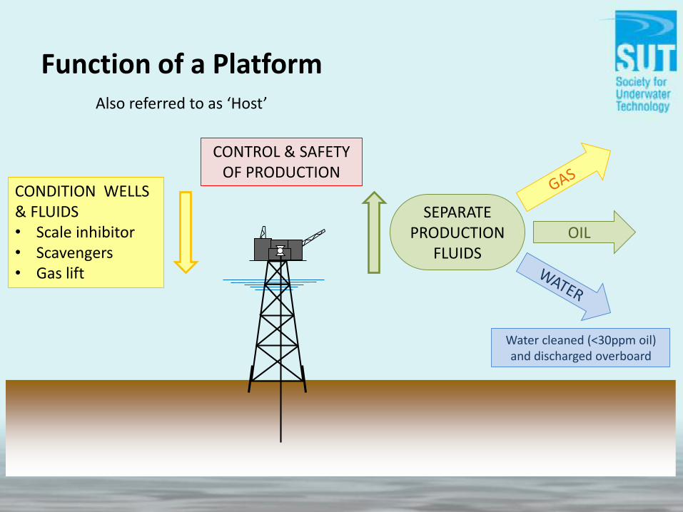
Function of a Platform
CONDITION WELLS & FLUIDS• Scale inhibitor• Scavengers• Gas lift
SEPARATE PRODUCTION
FLUIDSOIL
Water cleaned (<30ppm oil) and discharged overboard
CONTROL & SAFETY OF PRODUCTION
Also referred to as ‘Host’
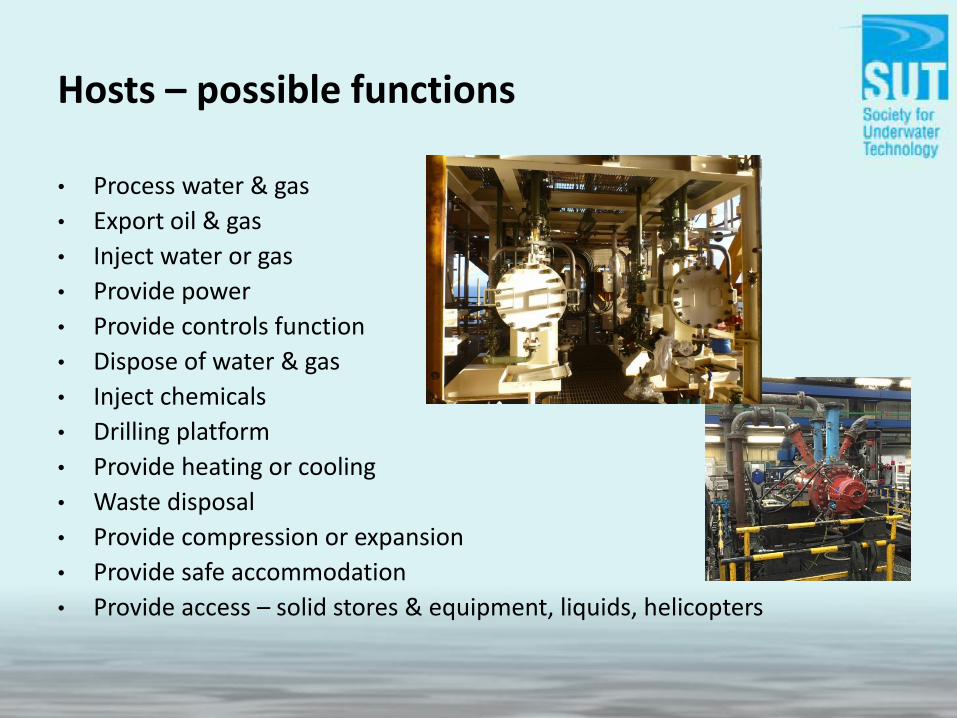
Hosts – possible functions
• Process water & gas
• Export oil & gas
• Inject water or gas
• Provide power
• Provide controls function
• Dispose of water & gas
• Inject chemicals
• Drilling platform
• Provide heating or cooling
• Waste disposal
• Provide compression or expansion
• Provide safe accommodation
• Provide access – solid stores & equipment, liquids, helicopters

Platforms
Subsea christmas trees
• Range of platform wells was limited
• Large reservoirs required multiple sites
• Multiple platforms uneconomic
• Why not drill remote from platform, with tree on seabed?
• Shell experimented with single well and wet tree close to Brent Bravo in early 1980s
• The beginning of subsea engineering as we know it today
• Safe isolation requires a minimum of two valves in sequence
• Pressures of 150 – 200 bar common; some are over 700 bar
• Modern wet tree looks nothing like Christmas tree…

Typical subsea tree

Simplified schematic of well – wet tree
Note: deviated well (can now be drilled from platforms too)

Subsea manifolds
• Platforms support many wells
• If this is to be replicated subsea, multiple wells must be tied back
• One way would be to connect each tree back to the host by individual pipelines
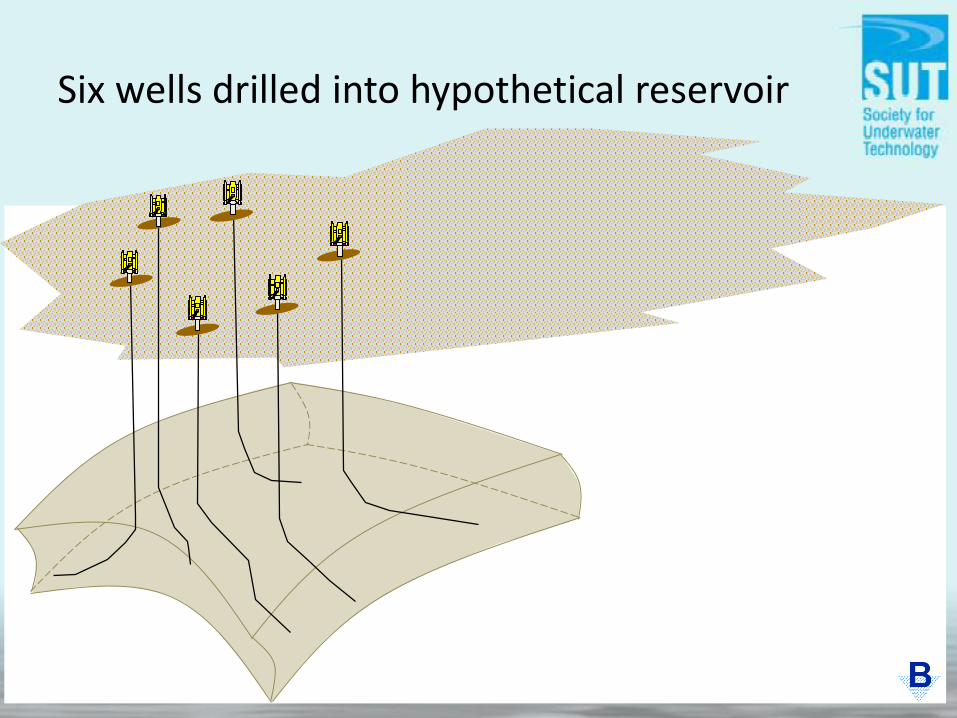
Six wells drilled into hypothetical reservoir

One pipeline per well… a very expensive solution
• Problem: all trees also require control umbilicals, and many require gas lift to initiate, and possibly maintain, flow
• Many pipelines – simply not economic• Therefore we employ subsea manifolds

Wells tied into subsea manifold

Schematic of subsea tie-back
TREE
UPMV
LPMVPWV
CHOKE
PIV
SCSSSV
MANIFOLD
MANUAL ISOLATION
VALVE
REMOTELY ACTUATED ROUTING
VALVE
FLOWLINE ISOLATION
VALVE
REMOTELY ACTUATED PIGGING
VALVE
SUBSEA ISOLATION
VALVES (SSIV)
RISER EMERGENCY SHUTDOWN
VALVES (RESDV)
HOST
NOTE: MANIFOLD SCHEMATIC SHOWS ONLY THE PRODUCTION, GAS LIFT AND WATER INJECTION SYSTEMS. NO CONTROL SYSTEM OR CHEMICAL INJECTION COMPONENTS ILLUSTRATED.
WATER INJECTION
SYSTEM
GAS LIFT SYSTEM

Control systems
• Manifolds contain pipework for routing production
• Also pipework for gas injection and water injection
• Flow rates, pressures and temperatures must be monitored
• Valves used to isolate or divert flow – must be controlled
• Chemicals may need to be injected to condition the flow
• The trees require similar control and monitoring
• All must be done from the surface – from the host
• Electro-hydraulic control system– Master Control Station topsides
– Subsea Control Modules subsea
– Linked by control umbilical

Control communications

Subsea production control system
Subsea Infrastructure (including trees)
SCM Actuators CIUComms
SUTU
MCS EPU
DCS
Hydraulic fluid Electrical supply Inhibitors, etc
HPU CI skid
TUTU
Umbilical

Umbilical Components
Steel TubeThermoplastic Hose Integrated Power & Service
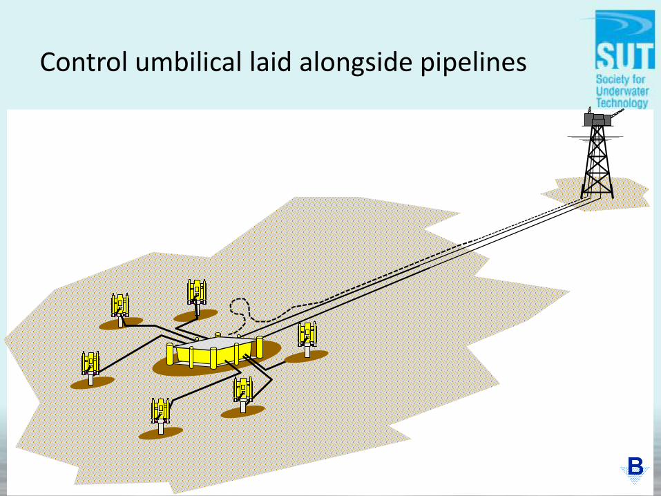
Control umbilical laid alongside pipelines

Water Injection trees
Production trees
Manifold
Umbilical
Production flowline A
Production flowline B
Water Injection flowline
Gas Lift flowline
POSSIBLE SUBSEA FACILITIES• Booster pumps• Separation (water, multiphase)• Power• Water winning• HIPPS • FSM (corrosion monitoring)Could be incorporated into the manifold, or on separate skids
Subsea facilities

Flowlines
• Pipelines required to carry produced fluids from manifolds to hosts –unprocessed multiphase fluids
• Referred to as production flowlines
• Pipelines also required to carry lift gas and injection water out to manifolds – also referred to as flowlines for consistency
• Production flowlines usually insulated and buried for both insulation (to prevent waxing, etc) and on-bottom stability
• Gas lift (GL) and water injection (WI) flowlines typically buried for protection if small diameter (<12”)
• Service flowlines (e.g. methanol) may be piggybacked on larger flowlines
• All these may be incorporated, together with control and chemical elements, within a single carrier – Pipeline Bundle

Piggyback flowline and pipeline bundle

Flexible pipes and risers
Brief Early History
1943 PLUTO – fuel pipelines laid across the Channel
1968 flexible flowlines laid between Vestmanna Islands and Iceland to provide drinking water after volcanic eruption
1973 first HP flexible flowline (Elf, Emeraude, Congo)
1974 Le Trait facility opened; first flexible flowline in North Sea (Mobil, Beryl)
1986 first dynamic production riser system installed (Sun Oil, Balmoral)
1991 flexibles reach 1000m water depth
2000 flexibles reach 1883m water depth - 6’’ Flowline (Petrobras, Roncador, Brazil)
2006 7.5” WI riser, 10,000psi, 1900m (BP Thunder Horse, GoM)
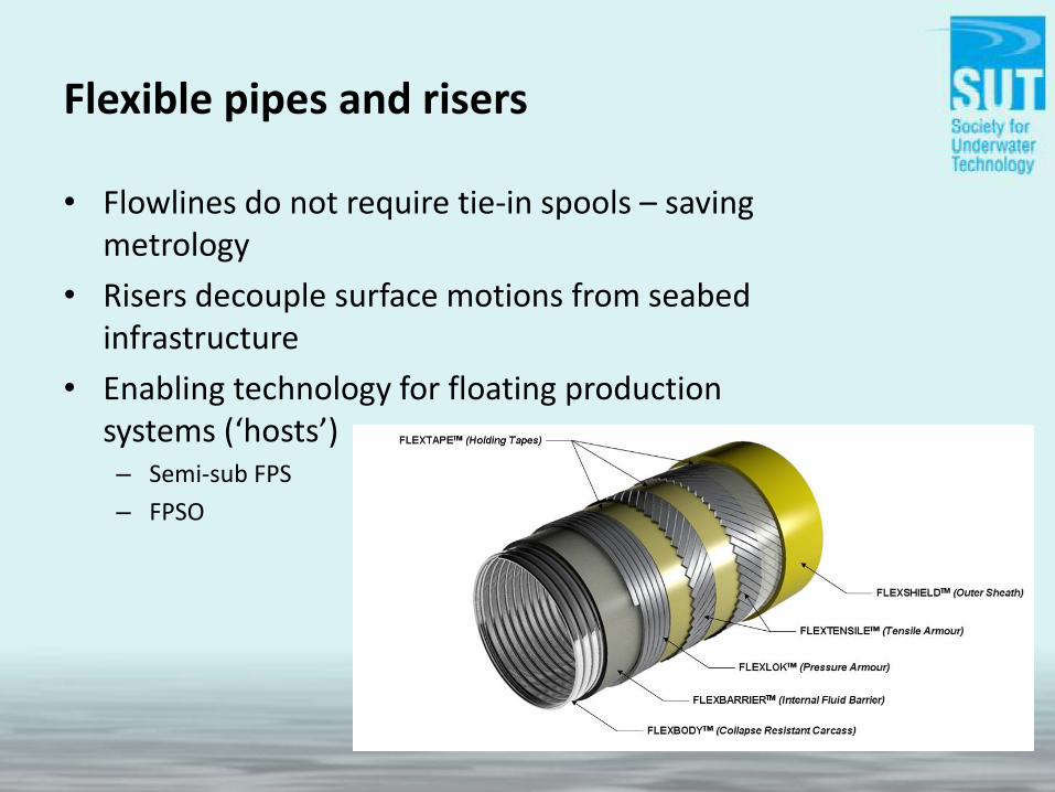
Flexible pipes and risers
• Flowlines do not require tie-in spools – saving metrology
• Risers decouple surface motions from seabed infrastructure
• Enabling technology for floating production systems (‘hosts’)– Semi-sub FPS
– FPSO

FPSOs
• The FPSO had a huge impact on the North Sea
• FPSO + subsea = cost-effective alternative to fixed platforms
• Subsea facilities became much more common
• Subsea step-outs from platforms where suitably located

Intervention
• Subsea systems are complex
• Subsea environment is aggressive – loads and corrosion
• Production fluids potentially corrosive and contain waxes, etc
• Damage through operations
• Third party damage – trawling, anchors
• Reliability and obsolescence of components
• Design for operational interventions – operate, test, replace
• For all these reasons, intervention is fundamental to subsea operations

Intervention
Installation DecommissioningOperations
Metrology
Location Condition
Commissioning
Survey, Inspection
Isolation, Cleaning
Well Workover
Tree / Manifold Intervention
Location, Condition
Isolation, Cleaning
Strategy“Will it work?”
Condition
Deformation
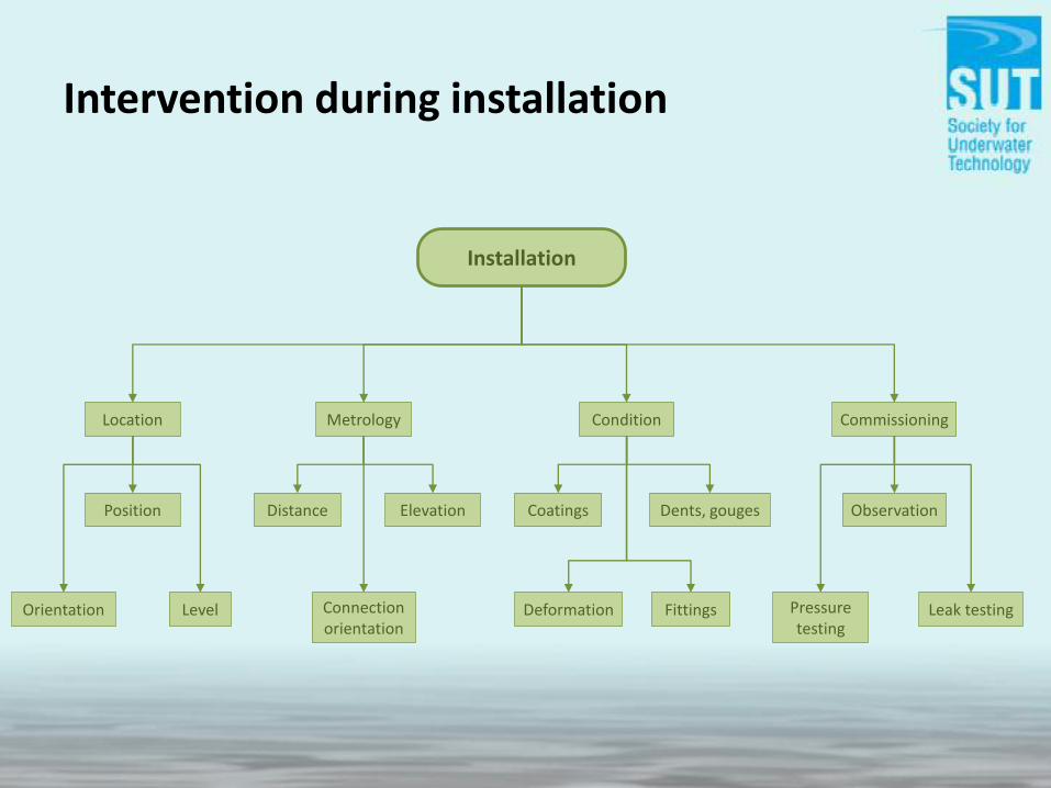
Intervention during installation
Installation
Location
Position
LevelOrientation
Distance Elevation
Metrology
Connection orientation
Dents, gougesCoatings
Pressure testing
Leak testing
Commissioning
Observation
Fittings

Intervention during operations
Operations
Survey, Inspection
Isolation, Cleaning
Well Workover
Tree / Manifold Intervention
What:• Structures•Moorings•Manifolds• Trees• Pipelines
What for:• Corrosion• Damage• Displacement• Leaks
Internal:• FMD• Pigging
External:• Visual: Diver, ROV• Sonar: SSS, MBES• AUV
Planned changes:• Choke• SCM
Unplanned changes:• Sensors, MPFM• Jumpers• Valves• Control components
Support:•Observation•Operation• Testing
What:• Pipelines, flowlines• Spools, jumpers•Manifold segments
Support:•Observation•Operation• Testing
What for:• Inspection• Repair• Replacement• Step-outs

Intervention during decommissioning
Decommissioning
Location, Condition
Plan for lifting:• Position•Orientation• Level• Lift points
Can it be lifted:• Corrosion• Damage• Deformation• Proof of lift points
Isolation, Cleaning
What:• Pipelines, flowlines• Spools, jumpers•Manifold segments•Umbilical cores
What for:• Partial removal• Prior to recovery
Strategy“Will it work?”
Why:• Pipeline removal methods• Spools with doglegs•Manifolds, structures
installed in multiple lifts