society of amateur radio astronomers - stray voltage ... of amteur radio astronomers 408 mhz...
TRANSCRIPT

Society of Amateur RadioAstronomers
408 MHz Radio Telescope SystemConstruction and Operations Manual
The receiver project described below was designed by SARA member JimCarroll and developed by other SARA members. We would like to thankthe following volunteers that helped bring this project to realization:
Receiver design: Jim CarrollPrototype construction: Chuck ForsterAntenna development: Hal BraschwitzSchematic artwork: Mike GingellThis manual: Chuck Forster
Thanks to members like Ken Watts who donated components for theprototype units and all the SARA members that provided the seed money tobegin this project.
This project is not completed, so additions, revisions and improvementswill occur from time-to-time. Please be sure you have the latest version ofthe manual and exhibits before beginning construction.
Please note that all the drawings and exhibits have been provided asseparate Adobe .pdf files. Note the date of the revision and the small letterafter the sheet number, i.e. RAc is the third revision to the sheet “RA”. Bymaking separate files, you can update you manual with a minimum ofdownloading and/or printing.
This manual and the information contained hereinremain the property of the Society of AmateurRadio Astronomers(SARA). All portions of themanual may be duplicated providing credit to theSociety of Amateur Radio Astronomers is givenand your readers are directed to the currentmembership director of our organization.

_________________________________________________ Society of Amteur Radio Astronomers
408 Mhz Reciever Project 2 Version9.0
Table of Contents
A. Description of the Receiver Project
B. Receiver Circuit Operation
C. Receiver Construction Techniques
D. Receiver Tuning and Alignment
E. Hints and Kinks:
F. Bill of Materials
G. Assistance:

_________________________________________________ Society of Amteur Radio Astronomers
408 Mhz Reciever Project 3 Version9.0
Antenna ExhibitsAA. Antenna Design ArticleAB. Antenna Construction Article
Hints for ConstructionHAa. Using “Z-wires”
Receiver ExhibitsRXb. System Block DiagramRAa. Receiver circuit board photo’s - Component sideRBb. Receiver circuit board photo’s - Foil sideRC. Receiver circuit board artwork - RF&IF moduleRD. Receiver component placement - RF moduleRE. Receiver component placement - IF/Det moduleRFb. Receiver circuit diagramRGb. Receiver power supply pre-regulator
Post Processor ExhibitsPAa. Post processor circuit board photo’s - Component sidePBa. Post processor circuit board photo’s - Foil sidePCa. Post processor circuit board artworkPDa. Post processor component placementPEb. Post processor circuit diagram - Page P1PFb. Post processor circuit diagram - Page P2PG. ReservedPHb. Post processor front panelPIa. Post processor front photoPJa. Post processor back of front panel photo
Temperature Stabilizer ExhibitsSA. Stabilizer circuit board photo’s - Foil sideSBa. Stabilizer circuit board photo’s - Component side*SC. Stabilizer circuit board artwork*SD. Stabilizer component placementSEb. Stabilizer circuit diagramSFa. Stabilizer internal parts layout photo*SG. Stabilizer front panel
Interconnection ExhibitsIA. Interconnection diagram
* indicates item was not produced at this time

_________________________________________________ Society of Amteur Radio Astronomers
408 Mhz Reciever Project 4 Version9.0
A. Description of the Receiver Project
For several years, a number of SARA members have sought to establish asimultaneous observation program as a means of doing constructivescience. With such a diverse range of expertise and observation interestscoupled with a very wide geographical dispersion of the membership, thisis yet to be accomplished. A major key to making useful simultaneousobservations is to employ equipment with similar and accurately knowncharacteristics at each site. The SARA Receiver addresses this requirementas well as providing a "plug-and-play" system for those unable to designand/or construct their own observatory.
From the beginning it was realized that a total system approach wasneeded, addressing not only the receiver itself but also packaging, gainstabilization, and interface with display and recording devices. Also,because this system is intended to fulfill the needs of an entry leveltelescope, cost and ease of installation and operation was consideredimportant. Lastly, because most users live in urban areas where RFinterference is often severe, portability to facilitate observation in moreremote and hopefully quieter locations was a design requirement.
The operating frequency of 406 to 410 MHz was chosen because RFcomponents for this frequency range are inexpensive, construction isstraight forward, relatively small antennas provide reasonable directivityand there are a fair number of high flux density sources to observe. Also,there is a lot of professional data available on observations made in thisfrequency band to compare amateur results with.
Over the five year evolution period, the receiver has taken three distinctforms. It began as a TRF receiver using printed circuit board strip lineresonators which made for a very low parts count, easy assembly and tune-up but the >20 MHz 3 dB bandwidth was just too broad for the amount ofclose-in interference encountered in the real world. The second model wasa superhet with a 70 MHz IF and used helical resonators for the RFfiltering. Though performance was excellent, construction of the RF filterswas rather difficult, which is not good for a low cost relatively highvolume unit.
The current design, also a superhet, uses discrete, LC RF filters withsufficient bandwidth to allow remote receiver tuning from 398 to 418MHz, a distinct advantage when escaping interference. The 2.5 MHz IFbandwidth is a compromise between interference avoiding selectivity and

_________________________________________________ Society of Amteur Radio Astronomers
408 Mhz Reciever Project 5 Version9.0
sensitivity which is proportional to the square root of the pre-detectionbandwidth. Except for some surface mount components in the RF circuits,the majority of the parts require no special handling. All components areavailable from a number of suppliers.
The complete system is composed of four assemblies; Antenna, Receiver,Post-detection Pre-processor, and the Receiver Housing TemperatureStabilizer. In addition, a source of 12 to 15V DC power at 2 amperesmaximum is needed to power the entire system. It has been designed suchthat the antenna and receiver can be used as a stand alone bare bones systemdriving a DVM or other type of digitizer or a strip chart recorder.External means of temperature stabilization such as Peltier heated/cooledchests or burying in the ground can be employed to reduce gain drift withtemperature. Later, the Receiver Housing Temperature Stabilizer can beadded, a must if truly portable operation is desired. Likewise, the Post-detection Pre-processor can be added to enhance interface flexibility andfacilitate system adjustments. At this time, it is envisioned that the lattertwo units will be constructed by the user from kits.
Electrical connections between the receiver and the rest of the system arevia standard hook-up wire for the power and heater/sensor wiring andshielded pair for the receiver and internal temperature sensor outputs.Power and heater wires should be sized for no more than 1V drop at thereceiver. Antenna connection is via 50 ohm coax with as short a length aspractical. Wire routing is users choice, but housing penetration must notcompromise weather resistance. A garden hose and associated fittingmounted on the outer housing end cap make an excellent conduit forinterface wiring and allows the housing to be pressurized through the hosefor further protection from water ingress, a definite consideration if thereceiver is to be buried to stabilize internal temperature. A waterproofbulkhead connector, mounted through the PVC end cap, can be used in thecoax path to maintain a weatherproof seal or the antenna coax can beconnected to the connector on the inner housing and the cable routedthrough a compression fitting on the end cap.
Construction is straight forward. A printed circuit board such as that to beprovided with the kit would look best but a perf-board will givesatisfactory electrical and mechanical performance. Grounding isimportant; use a well defined node to keep U5 and speaker ground currentsfrom getting into the signal path via C1, 2, 4 and 5. Either a plastic boxwith a metal panel or a metal chassis is acceptable just ground the metal tothe ground terminal of U8.

_________________________________________________ Society of Amteur Radio Astronomers
408 Mhz Reciever Project 6 Version9.0
Constructed as designed, this system meets all design objectives asdemonstrated in tests at NRAO and several locations in North Carolina.The major problem to be expected in real world operation will besusceptibility to interference caused by the relatively broad RF bandwidth.The ability to shift operating frequency to escape such interference willsolve most problems but there may be instances where the fourth harmonicof strong FM stations or the second harmonic of upper VHF band TVstations, especially Channels 11 and 12, will overpower the front end andmake operation impossible. The addition of a narrow band pass filterbetween the antenna and the receiver will greatly improve resistance to outof band interference but in band interference will still do its dirty work.When all else fails, do what the optical astronomers do, go portable.
Possible next steps to increase the capabilities of this system in the antennaarea include combining antennas in arrays to increase effective area, usingtwo or more antennas or arrays of antennas as an interferometer, andrepetitively switching between two collocated antennas, one looking at coldsky and the other pointed at the source under study. This latterconfiguration is quite helpful in overcoming interference as long as the twoantennas receive identical amounts of interference. In the receiver area,extensive processing of the output from the receiver or the Post-detectionpre-processor so as to dig deeper into the noise and interference to ferretout weak sources can greatly increase the sensitivity and dynamic range ofthis system.

_________________________________________________ Society of Amteur Radio Astronomers
408 Mhz Reciever Project 7 Version9.0
12 volt dcSupply
PostProcessor
Temp.Regulator
Radio Receiver
Antenna
50 ohm coax
Multi-conductrcable
SARA 408 Mhz Radio TelescopeOverall System Layout
Antenna
The antenna recommended as a minimum for this system is a single 15element Quagi. Larger antennas can certainly be used, in fact, the biggerthe better is usually the goal. However, as the antenna size increases, thecontribution of back and side lobes can becomes quite significant such thatmoderate sources like Cass A in a side lobe can obliterate the signal from aweak source being observed in the main beam.
Of course the Sun can play havoc with just about any size antenna. Anaccurate knowledge of the total antenna pattern and the affects of motion inazimuth and elevation on the shape and relative location of pattern artifactsis necessary before consistently usable data can be recorded. Antennas

_________________________________________________ Society of Amteur Radio Astronomers
408 Mhz Reciever Project 8 Version9.0
paired as an interferometer can also be used and are often quite effective inrejecting terrestrial interference.
The Quagi antenna is a hybrid combination of loop and cylindricalelements in a Yagi array. It consists of loop reflector and a loop drivenelement along with a number of cylindrical director elements. The loopdriven element was chosen as it presented fewer problems of matching andfeeding a transmission line.
Jim Carroll scaled the Overbeck1 design from 432 MHz to 408 MHz. Thisantenna has functioned very well for Jim Carroll in his radio astronomyefforts.
Hal Braschwitz optimized the Jim Carroll’s design with a computermodeling program to improvement in the design at our operatingfrequency.
B. Receiver Circuit Operation
The SARA Receiver is a single conversion superhet constructed on twomain printed circuit boards; one containing the RF amplifier, mixer, andlocal oscillator and the second the IF amplifier, detector, DC amplifier,temperature sensor, and voltage regulator. A thermostat is mounted on athird board which also has some room for future circuit additions. BrassU-rails mechanically interconnect the individual boards and ensure goodelectrical bonding between the top and bottom ground planes.
The entire receiver in contained within a 24 inch long piece of one inchschedule L copper pipe which serves as an inner housing, an electricalshield, and a temperature stabilizing thermal mass. Completelysurrounding the pipe are two overlapping coils of copper wire, one servingas a heater and the other as a temperature sensor. These are used tostabilize the receiver operating temperature and interface with the optionalReceiver Housing Temperature Stabilizer. The copper pipe is surroundedby foam pipe insulation and the assembly is inserted in a 36 inch long pieceof two inch schedule 40 PVC pipe which serves as a rugged weatherproofouter housing.
The RF amplifier uses an ATF-21186 GaAsFET for the front end followedby a MAR-6 MMIC in a configuration popularized by Al Ward for LNAsfor ham applications. Inductor L2 together with Q1's input capacitance 1 Wayne Overbeck

_________________________________________________ Society of Amteur Radio Astronomers
408 Mhz Reciever Project 9 Version9.0
form a low Q series tuned circuit which serves as the input RF band passfilter. The other components in the vicinity of Q1 and U2 serve ascoupling, biasing, and bypass elements. A regulated voltage source for Q1is provided by U1. An attenuator, formed by R6-8, allows the total gain ofthis board, from RF in to mixer out, to be set to 40 dB in all receivers. Asecond RF band pass filter is formed by L3, L4, and C12-15. AdditionalRF gain is provided by U3 with the surrounding components serving ascoupling, biasing, and bypass elements. Two test points facilitate test andtune-up.
Module U5 is a voltage controlled oscillator that serves as the localoscillator. The associated resistor network biases the frequency adjustmentinput such that with a 0 to +10V control voltage, the oscillator can beremotely tuned from 328 to 348 MHZ which corresponds to a 398 to 418MHz receive frequency. Module U4 is a balanced mixer that receives lowside local oscillator injection from U5 and RF from U3 and produces sumand difference frequency outputs. The difference, 70 MHz, is used as thereceiver IF.
The IF is applied to a low pass filter made from L5 and C23-26 whichrejects signals above 75 MHz and also functions as a capacitive terminationfor the mixer IF port at local oscillator frequencies and above. The firstIF stage uses U6, a MAR-6 MMIC, for gain and L6, 7 and C29-35 as a 70mHZ double-tuned band pass filter with 2.5 mHz bandwidth. The othercomponents serve for coupling, biasing and bypassing. The remaining twotuned IF stages are identical to U6 except that MAR-1 MMICs are used.Attenuator R19-21 is used to set the total IF gain to a nominal 65 dB whichproduces approximately -10 dBm drive to the detector with a 50 ohmreceiver input termination at 20 degrees C.. The fourth stage, U9 andassociated components, completes the IF amplifier.
Germanium diode D1 functions as a square law detector and R24,25 andC55, 56 provide termination and post-detection filtration. Op-amp U10/Aand R26, 27 form a X100 DC amplifier which amplifies the nominal 10mV from the detector to around 1V for feeding external equipment.Precision temperature sensor U11 is physically mounted in the vicinity ofthe most temperature sensitive element in the receiver, the detector, andproduces an output of 10 mV per degree C. Op-amp U10/B with R29, 30amplify U11's output X10 such that if the internal temperature is 50degrees C, a +5V DC signal is produced. Low drop-out voltage regulatorU12 and voltage setting components R29-31 provides stable +10.5V powerfor the receiver electronics. A second low drop-out voltage regulator,external to the inner housing but within the outer housing, regulates the

_________________________________________________ Society of Amteur Radio Astronomers
408 Mhz Reciever Project 10 Version9.0
incoming raw 12 to 15V DC to 11V which feeds U12. This also assists intemperature stabilization as the power dissipation within the inner housingis kept constant for a wide range of raw DC supply voltages.
Post Processor
The Post-detection Pre-processor serves as an interface between thereceiver and the analysis and recording equipment that follows as well asproviding a simple means of tuning the receiver and monitoring itsperformance. A differential amplifier with a voltage gain of two, U1 andassociated components, accepts the amplified detector output from thereceiver and produces an unbalanced output for external processing via theterminal AMP OUT 1, feeds the internal audio amplifier/speaker throughswitch S4, and drives the limiter U2/A. It should be noted that a separatesignal ground is routed from the receiver and is to be connected to the - INterminal on the processor while the amplified detector output goes to the +IN terminal. If the power ground connection were to be used, the voltagedrop in this ground wire will be algebraically added to the desired signaland any changes in this voltage drop will cause a corresponding change inthe desired signal.
Limiter U2/A is activated by switch S1 and provides a means ofsignificantly reducing the effects of impulse noise such as ignitioninterference or lightning. Components R8, 9 and C4, 5 form an RC lowpass filter with time constants of 1, 4, and 16 seconds as selected by switchS2. Op-amp U2/B and R11, 12 form a DC amplifier with a voltage gain of1.16 which buffers the RC filter and provides a dynamic voltage referenceto the limiter such that signals more than 16% in voltage above the RCfilter output are clipped. Filter R10, C6 and steering diode D2 ensureproper start up of the limiter circuit.
The output of U2/B passes through R17 to the inverting input of op-ampU3/A which serves as a summing node also fed by the coarse and fineoffset controls R13 and R14 through R15 and R16 and has a voltage gain of1.72. This allows the residual output caused by receiver noise to be nulledout and makes changes in the receiver output due to received signals moreprominent. Op-amp U3/B and associated components provides DC voltagegains of 1, 5, and 25 as selected by switch S3. This results in total gains of4, 20, and 100 for the entire processor signal path. The output of U3/B isavailable for further processing or direct recording through terminal AMPOUT 2 and also drives the voltage controlled oscillator U4 whose squarewave output frequency is directly proportional to the input voltage. Thissignal is available at terminal VCO OUT and can drive a PC sound card, a

_________________________________________________ Society of Amteur Radio Astronomers
408 Mhz Reciever Project 11 Version9.0
DSP unit or an external frequency counter which can serve as a digitalsignal strength integrator. This same signal, attenuated by R25, 26, feedsthe audio amplifier/speaker via S4.
Audio amplifier U5 and associated components and the internal speakerallows audible monitoring of the receiver. With the AUDIO SEL switch inthe VCO position, offset adjustments are made by using the tone pitch as anaudible voltmeter. An external speaker, connected to SPKR OUT andlocated at the antenna site, can facilitate antenna positioning when theAUDIO SEL switch is in the VCO position and locating interferencesources in the AMP position.
Low drop-out voltage regulator U8 provides +10V for all processorcircuits. Multivibrator U7, voltage regulator U6, and associatedcomponents produces a source of regulated -5V for the op-amps and theoffset potentiometers. Remote receiver tuning is provided by R33 viaterminal REM TUNE.
Temperature Stabilizer
Because of the relatively broad beam widths of the antennas we as amateurscan afford to build or buy, it takes a long time for a source to drift throughthe beam. During this time any gain changes caused by temperature,supply voltage, or other parameter variations will become painfullyevident, especially when the equipment is operated at high sensitivity, andcan distort or totally obscure the desired signals. Using two or moreantennas in an interferometer configuration will help significantly butmany observers don't have the necessary real estate to set up such a systemand large antenna separation will require pre-amps.
To minimize drift due to supply voltage variations in the SARA Receiver,double voltage regulation is used in feeding the +10.5V DC bus that powersall of the receiver electronics. Temperature related drift can best beaddressed by stabilizing the operating temperature of all temperaturesensitive components in the receiver. In addition to the external means oftemperature stabilization mentioned earlier, maintaining a constanttemperature within the inner housing will accomplish the same resultwithout sacrificing portability or consuming excessive electrical power.
The Receiver Housing Temperature Stabilizer utilizes the twoaforementioned coils of copper wire surrounding the inner housing tocreate a proportionally controlled oven. This technique was chosen over acyclic controller to eliminate oven heater switching transients which could

_________________________________________________ Society of Amteur Radio Astronomers
408 Mhz Reciever Project 12 Version9.0
magnetically couple into the received signal wire if the oven power leadsare in close proximity. One coil, wound with #24 wire and having aresistance of approximately seven ohms, serves as the heater and the secondcoil using #38 wire has about 200 ohms of resistance and is the temperaturesensor. The regulation stiffness is greater than 50, that is a 50 degree Cchange in outside temperature results in less than one degree change ininternal temperature.
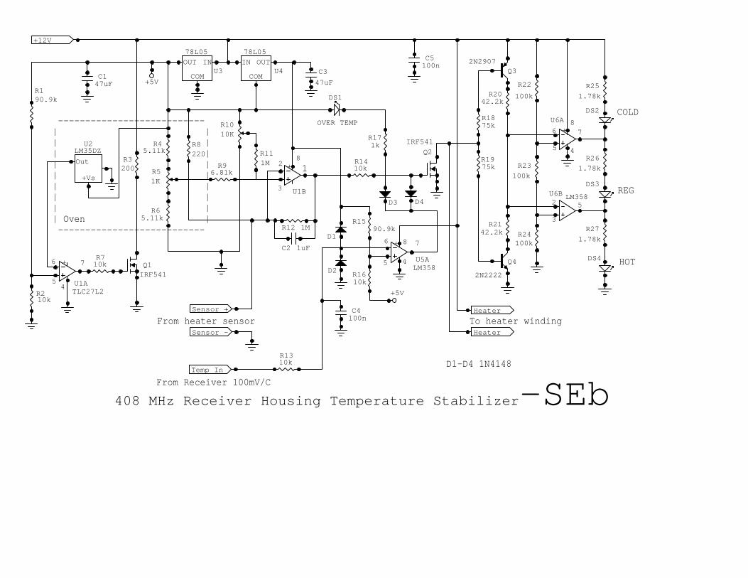
Looking at the Stabilizer schematic, it can be seen that the temperaturesensor is one arm of a Wheatstone bridge with R8 the second arm, R4 plusthe top part of R5 the third arm, and the bottom part of R5 plus R6 makingup the fourth arm. Regulated power for the bridge is furnished by U3.Op-amp U1/B and associated components form a DC amplifier whichamplifies voltages due to bridge unbalance and drives power MOSFET Q2which in turn drives the heater. The operating temperature is set by R5and R10. The temperature regulation status of the stabilizer is derivedfrom the heater voltage such that if there is no voltage across the heater thetemperature exceeds the set point. If the full supply voltage is across theheater the temperature is below the set point. If the heater voltage isbetween the above limits the temperature is in regulation. Op-amps U6/Aand B, functioning as comparators, along with Q3, 4 determine the heatervoltage range and drive the appropriate indicator DS2-4.
To reduce the effects of Stabilizer ambient temperature changes on thebridge components, arms two through four are enclosed in a small ovenstabilized at 50 degrees C. Precision temperature sensor U2, which isthermally coupled to the bridge components and to heater R3 with lowthermal resistance epoxy, drives op-amp U1/A which compares U2's outputwith the set point voltage produced by R1, 2 and drives MOSFET Q1which in turn drives the heater.
Op-amp U5/A and associated components compare the output of theprecision temperature sensor in the receiver with a reference voltageproduced by R15, 16 and, through D4, turns off Q2 if the internaltemperature exceeds 55 degrees C. At the same time, flashingOVERTEMP indicator DS1 is activated through D3. This protects thereceiver components from thermal damage if the operating temperature isinadvertently set too high. A thermostat, designed to open at 60 to 70degrees C, is mounted within the inner housing and electrically connectedin series with the heater winding and serves as a backup shut-down if afailure within the Stabilizer locks Q2 permanently on.
Power

_________________________________________________ Society of Amteur Radio Astronomers
408 Mhz Reciever Project 13 Version9.0
The entire system will run all evening on a 12 volt motorcycle battery.This allows operation in a remote location without costly and timeconsuming setup.
C. Receiver Construction Techniques
The copper receiver is covered with a section of 1 inch water pipe foamavailable at any hardware center. The foam covered receiver and foam isslipped into a PVC pipe also commonly available.
Copper pipe end caps are used on each end of the radio unit and PVC pipeend caps are used on the outer PVC pipe housing. Holes are bored in eachend cap to facilitate input/output connections.
PVC cap
FoamReceiver
RF InputPVC pipe
Receiver HousingCut-a-Way View
(Input end)
_________________________________________________ Society of Amteur Radio Astronomers
408 Mhz Reciever Project 14 Version9.0
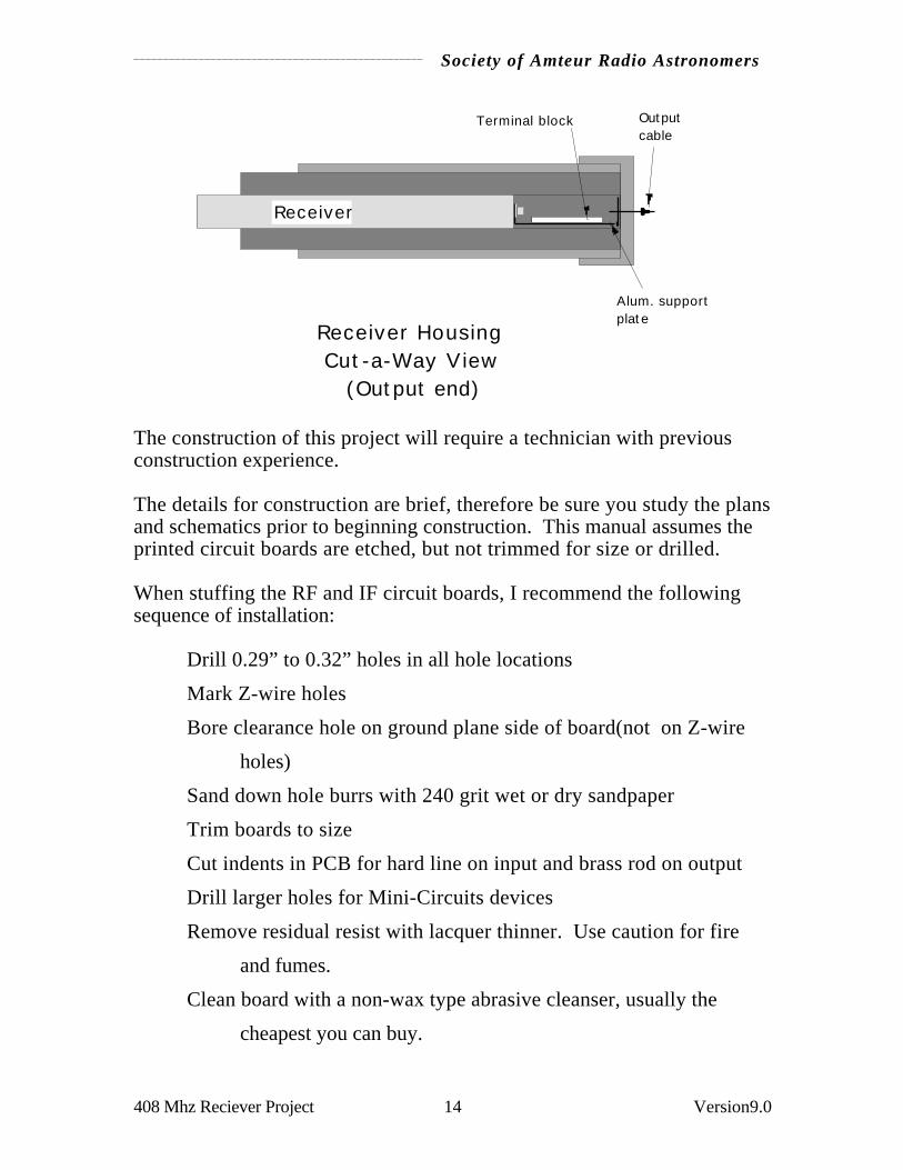
Receiver
Alum. supportplate
Receiver HousingCut-a-Way View
(Output end)
Terminal block Outputcable
The construction of this project will require a technician with previousconstruction experience.
The details for construction are brief, therefore be sure you study the plansand schematics prior to beginning construction. This manual assumes theprinted circuit boards are etched, but not trimmed for size or drilled.
When stuffing the RF and IF circuit boards, I recommend the followingsequence of installation:
Drill 0.29” to 0.32” holes in all hole locations
Mark Z-wire holes
Bore clearance hole on ground plane side of board(not on Z-wire
holes)
Sand down hole burrs with 240 grit wet or dry sandpaper
Trim boards to size
Cut indents in PCB for hard line on input and brass rod on output
Drill larger holes for Mini-Circuits devices
Remove residual resist with lacquer thinner. Use caution for fire
and fumes.
Clean board with a non-wax type abrasive cleanser, usually the
cheapest you can buy.

_________________________________________________ Society of Amteur Radio Astronomers
408 Mhz Reciever Project 15 Version9.0
Solder Z-wires
Install variable capacitors
Install other low height devices
Install active RF and IF devices last
D. Receiver Tuning and Alignment
Tuning and alignment will require the use of a stable signal generator. Asweep generator and spectrum analyzer will be very useful.
Install a potentiometer (20k) in place of the resistor R34. Be sure the potis set at mid-range. Apply 12 volt power to the unit and adjust R34 until+10.5 vdc is measured along the 10.5 vdc bus on the receiver. Replace thepot with a fixed resistor R34 equal to the pot value.
Input 5.0 vdc into the remote tune wire (yellow).
Turn off power and install a potentiometer (10k) in place of the resistorR12. Be sure the pot is set at mid-range. Apply 12 volt power to the unitand adjust R12 until the local oscillator output is 338 mHZ. (338 mHZ +70 mHZ = 408 mHZ) Replace the pot for R12 with a resistor equal to thepot value. Consider the use of 2 resistors in series to total the exact potvalue.
Apply a 70 mHZ signal at the input to the IF module and tune the six (6)variable capacitors for a double tuned passband centered about 70 mHZ. Ifa sweep generator is not available, use a signal generator and tune formaximum output at the receiver dc output. Keep the input 70 mHZ signallow so the IF stages do not overload.
Apply a 408 mHZ signal at the input to the RF module and tune inputinductor “L2” for a peak. Detect the input tuning with an RF detectorprobe connected to the test point near U1.
Tune the two (2) “L3” coils for a double tuned passband at 408 mHZ.Detect the tuning with an RF detector probe connected to the test point nearU4.
Tuning is accomplished by spreading and compressing the coil windingswith a non-metallic tool.
_________________________________________________ Society of Amteur Radio Astronomers
408 Mhz Reciever Project 16 Version9.0
If a sweep generator is not available, use a signal generator and tune formaximum output at the receiver dc output. Keep the input 408 mHZ signallow so the RF and IF stages do not overload.
Apply power to the unit and measure the tuning voltage required to tune408 mHZ (338 mHZ out of the local oscillator).
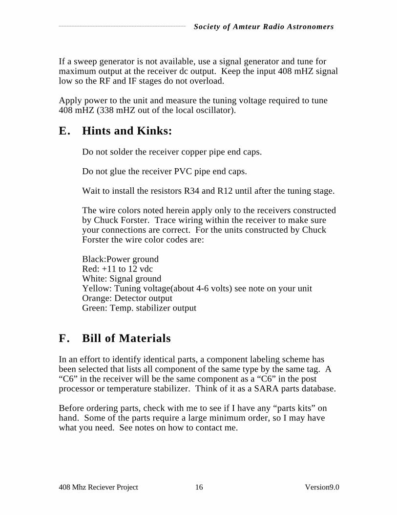
E. Hints and Kinks:
Do not solder the receiver copper pipe end caps.
Do not glue the receiver PVC pipe end caps.
Wait to install the resistors R34 and R12 until after the tuning stage.
The wire colors noted herein apply only to the receivers constructedby Chuck Forster. Trace wiring within the receiver to make sureyour connections are correct. For the units constructed by ChuckForster the wire color codes are:
Black:Power groundRed: +11 to 12 vdcWhite: Signal groundYellow: Tuning voltage(about 4-6 volts) see note on your unitOrange: Detector outputGreen: Temp. stabilizer output
F. Bill of Materials
In an effort to identify identical parts, a component labeling scheme hasbeen selected that lists all component of the same type by the same tag. A“C6” in the receiver will be the same component as a “C6” in the postprocessor or temperature stabilizer. Think of it as a SARA parts database.
Before ordering parts, check with me to see if I have any “parts kits” onhand. Some of the parts require a large minimum order, so I may havewhat you need. See notes on how to contact me.

_________________________________________________ Society of Amteur Radio Astronomers
408 Mhz Reciever Project 17 Version9.0
Most parts suppliers are on the internet. Contact the supplier for a freecatalog:
Amidon Corp http://www.amidoncorp.comDigi-Key Products http://www.digikey.com/HP Device Information http://hpcc920.external.hp.com/HP-COMPMECI http://www.meci.com/mecihome.htmMouser Products http://www.mouser.com/Penstock http://www.penstock.avnet.com/
From Digi-key:SARAPart Qty DescriptionC1 4 120pF 50V 5% NPO Ceramic Chip 0805 Digi-Key PCC121CGCT-NDC2 2 10nF 50V 5% X7R Ceramic Chip 0805 Digi-Key PCC1O3BNCT-NDC3 2 1nf 50V 5% X7R Ceramic Chip 0805 Digi-Key PCC1O2BNCT-NDC6 9 1nf 100V 10% X7R Monolithic Ceramic Digi-Key P4898-NDC9 2 100pf 100V 5% COG Monolithic Ceramic Digi-Key P4849-NDC10 6 l0nF 63V 10% X7R Monolithic Ceramic Digi-Key P4881-NDC20 2 luF35V 10% Dipped Tantalum Digi-Key P2059-NDC23 2 68pf 100V 5% COG Monolithic Ceramic Digi-Key P4847-NDC24 2 22pF 1OOV 5% COG Monolithic Ceramic Digi-Key P4841-NDC30 6 3.5-l0pF 100V NPO +/- 200 Plastic Var. Digi-Key SG1029-NDC31 6 27pF 100V 5% COG Monolithic Ceramic Digi-Key P4842-NDC57 1 100 nF 63V 20% ZSU Monolithic Ceramic Digi-Key P4917-NDC58 1 22uF 16V 10% Dipped Tantalum Digi-Key P2040-NDL1 1 220nH 20% Surface Mount Inductor Digi-Key TKS1O17CT-NDFL1 2 Low Pass Power Buss Filter lOOpF T Digi-Key P9803CT-NDFL3 4 Low Pass Power Buss Filter lOnF T Digi-Key P9809CT-NDR1 3 100 1/l0W 5% Thick Film Chip 0805 Digi-Key P100ACT-NDR2 1 47 1/l0W 5% Thick Film Chip 0805 Digi-Key P47ACT-NDR3 1 150 1/l0W 5% Thick Film Chip 0805 Digi-Key P15OACT-NDR4 1 10 1/4W 1% Metal Film Digi-Key 10. OXBK-NDR5 2 330 1/lOW 5% Thick Film Chip 0805 Digi-Key P33OACT-NDR7 1 68 1/lOW 5% Thick Film Chip 0805 Digi-Key P68ACT-NDR10 1 42.2K 1/4W 1% Metal Film Digi-Key 42. 2KXBK-NDR11 3 6.81K 1/4W 1% Metal Film Digi-Key 6. 8lKXBK-NDR12 1 about 10 k Metal Film Digi-Key ???K XBK-NDR34 1 about 10 k Metal Film Digi-Key ???K XBK-NDR13 1 2.21K 1/4W 1% Metal Film Digi-Key 2. 21KXBK-NDR14 3 100k 1/4W 1% Metal Film Digi-Key 100KXBK-NDR16 4 332 1/4W 1% Metal Film Digi-Key 332XBK-NDR19 1 100 1/4W 1% Metal Film Digi-Key 100 XBK-NDR20 1 68.1 1/4W 1% Metal Film Digi-Key 68.1 XBK-NDR21 1 100 1/4W 1% Metal Film Digi-Key 100 XBK-NDR23 1 46.4 1/4W 1% Metal Film Digi-Key 46. 4XBK-NDR24 1 1M 1/4W 1% Metal Film Digi-Key 1MXBK-NDR25 1 10K 1/4W 1% Metal Film Digi-Key 1OKXBK-NDR26 2 1k 1/4W 1% Metal Film Digi-Key 1KXBK-NDR28 2 237 1/4W 1% Metal Film Digi-Key 237XBK-NDR29 1 61.9K 1/4W 1% Metal Film Digi-Key 61. 9KXBK-NDU10 1 CMOS Op-Amp National LMC662CN Digi-Key LMC662CN-NDU11 1 Celsius Tempe. Sensor National LM35DZ Digi-Key LM35DZ-ND

_________________________________________________ Society of Amteur Radio Astronomers
408 Mhz Reciever Project 18 Version9.0
U12 1 Adj. Low Dropout Reg. National LM2941CT Digi-Key LM2941CT-ND
From Mouser:SARAPart Qty DescriptionC12 2 3pF 50V 10% NPO Ceramic Disc Mouser 140-CD5ON6-003KC13 8 6.8pF 500V 5% NPO Ceramic Disc Mouser 141-500N2-6. 8JC32 3 2pF 100V 5% NPO Ceramic Disc Mouser 141-100N2-002JD1 1 Germanium Diode 1N60 Mouser 333-1N60Ul 1 +5V Regulator National LM78L05AC Mouser 511-L78L05ACZ
From Amidon:SARAPart Qty DescriptionFB1 7 "Single Hole Ferrite Bead 0.138 X 0.236""; Type 43 Material"
Amidon FB-43-301L5 1 90nH Toroidal Inductor 6T #22 on T-25-10 core Amidon T-25-1OL6 6 l20nH Toroidal Inductor 9T #24 on T-25-12 core Amidon T-25-12
From Penstock: ($100 minimum order)SARAPart Qty DescriptionQ1 1 GaAs FET RF Amplifier HP ATF-21186 Penstock(770-734-9990)
From MECI:SARAPart Qty DescriptionS01 1 TNC Female Crimp-On Bulkhead Conn. MECI 240-1454 (1-800-344-4465)
From Mini-Circuits:SARAPart Qty DescriptionU2 2 MMIC RF Amplifier MOL MAR-6 Mini-CircuitsU3 4 MMIC RF Amplifier MCL MAR-1 Mini-CircuitsU4 1 Double Balanced Mixer MCL SBL-1 Mini-CircuitsU5 1 Voltage Cont. Oscillator MCL POS-535 Mini-Circuits
From Chuck Forster if a “Parts Kit” is availableWire stock 1 lot #24 copper wireWire stock 1 lot #22 copper wire0.141 rigid coax 7 inchesBrass edge channel 3 ft. "3/32"" O.D. square brass tube""0.286"" O.D. brass tube" 5 ft."1.2"" x 0.29"" springs" 1Threaded lamp rod 4 inchesRod nuts 2Rg-174 mini coax 1 ft.PC board - RFPC board - IFPC board - Post processorPC board - Temperature stabilizer22 ga. solder
_________________________________________________ Society of Amteur Radio Astronomers
408 Mhz Reciever Project 19 Version9.0
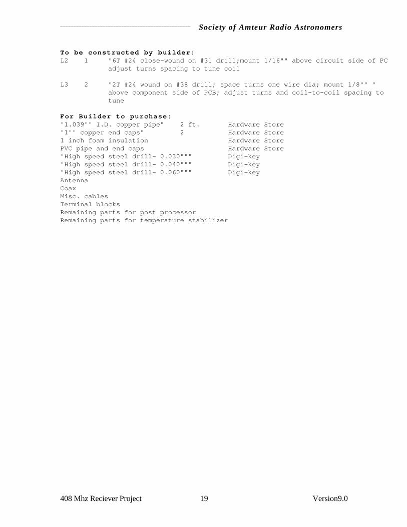
To be constructed by builder:L2 1 "6T #24 close-wound on #31 drill;mount 1/16"" above circuit side of PCB"
adjust turns spacing to tune coil
L3 2 "2T #24 wound on #38 drill; space turns one wire dia; mount 1/8"" "above component side of PCB; adjust turns and coil-to-coil spacing to tune
For Builder to purchase:"1.039"" I.D. copper pipe" 2 ft. Hardware Store"1"" copper end caps" 2 Hardware Store1 inch foam insulation Hardware StorePVC pipe and end caps Hardware Store"High speed steel drill- 0.030""" Digi-key"High speed steel drill- 0.040""" Digi-key"High speed steel drill- 0.060""" Digi-keyAntennaCoaxMisc. cablesTerminal blocksRemaining parts for post processorRemaining parts for temperature stabilizer

_________________________________________________ Society of Amteur Radio Astronomers
408 Mhz Reciever Project 20 Version9.0
Using the “SARA” database parts numbering scheme, the following is an index tothe full list of parts numbers used in the text and on the receiver schematicdiagrams.
C1,8,11,17 C2, 5C3, 4 C6,7,18,19,27,52,54,55,56C9,16 C10,21,28,36,44,53C12,15 C13,14,29,35,37,43,45,51C20,59 C23,26C24,25 C30,34,38,42,46,50C31,33,39,41,47,49 C32,40,48C57 C58D1FB1,2,3,4,5,6,7 FL1,2FL3,4,5,6L1 L2L3, 4 L5L6,7,8,9,1O,11Q1R1,6,8 R2R3 R4R5, 9 R7R10 R11,30,32R12 R13R14,15,27 R16,17,18,22R19 R20R21 R23R24 R25R26,33 R28,31R29 R34S01UlU2, 6U3,7,8,9U4U5U10U11U12

_________________________________________________ Society of Amteur Radio Astronomers
408 Mhz Reciever Project 21 Version9.0
G. Assistance:
I prefer that all contacts to me be made via internet, fax or by letter. Youcan call, but the chance of catching me is slim. I will probably not returnyour call, not to be unfriendly, but SARA should not spend money for meto return calls.
I can be reached at:
Chuck Forster5420 Glenway CircleOregon, WI 53575608-835-9282 voice608-835-9039 [email protected]
The parts kits are in limited supply, about five (5) left at this time(6/98). Iwill order more parts if the demand is sufficient.
If you construct a receiver and need help tuning the unit, I will tune it andrepair it for $40 (includes return shipping in the US), plus the cost of anyreplacement parts. If anyone else would like to offer this service, I wouldappreciate the help.
Chuck

A 408 MHz Quagi Receiving Antennafor
Radio Astronomy
By Hal Braschwitz and Jim Carroll
One tangible result of the 1996 conference of the Society of Amateur RadioAstronomers (SARA) was the organization of a program to produce anumber of 408 MHz receivers of the design Jim Carroll has beendeveloping for several years.
One purpose of this endeavor was to achieve a long time SARA goal ofoperating more than two observatories in concert.
This article presents an antenna design suitable for use with the SARAreceiver. Jim Carroll demonstrated a prototype of this antenna at the 1990SARA Conference. It was a version of an antenna Wayne Overbeckdescribed in the April, 1977 issue of QST Magazine and was called a"Quagi Antenna."
A companion article by Chuck Forster covers the construction of the 408Mhz Quagi.
The Quagi is a hybrid combination of loop and cylindrical elements in aYagi array. It consists of loop reflector and a loop driven element alongwith a number of cylindrical director elements. The loop driven elementwas chosen as it presented fewer problems in matching and feeding atransmission line.
Jim Carroll scaled the Overbeck design from 432 MHz to 408 MHz. Thisantenna has functioned very well for Jim Carroll in his radio astronomyefforts.
Tom Crowley and Chuck Forster, present and immediate past SARAPresidents of SARA, asked us to look into the Overbeck design withcurrent computer modeling programs to see if further improvements in thedesign could be made.

Design of the SARA 408 Mhz Antenna _____________________________________________
Hal Braschwitz 2 6/1/97
Figure 1 shows the antenna geometry.
Figure 1 - View of antenna as shown by the analysis program.

Design of the SARA 408 Mhz Antenna _____________________________________________
Hal Braschwitz 3 6/1/97
Figures 2 and 3 show the free space elevation and azimuth patterns of theoriginal 432 MHz Quagi antenna array. The driving point impedance at432 MHz is 54.4 + J 10.18 ohms.
Figure 2 - An elevation pattern plot of the 432 Mhz design.

Design of the SARA 408 Mhz Antenna _____________________________________________
Hal Braschwitz 4 6/1/97
Figure 3 - An amimuth pattern plot of the 432 Mhz design.
This quagi antenna consists of a loop reflector and loop driven elementalong with 13 straight wire type director elements. The W7EL EZNECcomputer program was used to model the antenna described in this article.EZNEC is a version of the NEC2 antenna modeling program.
The W7EL EZNEC computer program shows the 432 MHz array to have afree space gain of 15.85 dBi (decibels gain compared to an isotropicradiator). It has a horizontal and vertical beamwidth of 28 degrees and afront to back ratio of 12.16 dB along with a number of lesser side lobes.See figures 2 and 3 above.
The modified antenna array version shown below for our applicationexhibits about the same forward gain, improved front to back ratio andsimilar side-lobe patterns.
Mechanically, most of the director elements are of constant length ratherthan being of varying lengths and therefore yields simpler assembly. Thefree space elevation and azimuth patterns are shown in Figures 4 and 5.

Design of the SARA 408 Mhz Antenna _____________________________________________
Hal Braschwitz 5 6/1/97
Figure 4 - An amimuth pattern plot of the 408 Mhz design.
Design of the SARA 408 Mhz Antenna _____________________________________________
Hal Braschwitz 6 6/1/97
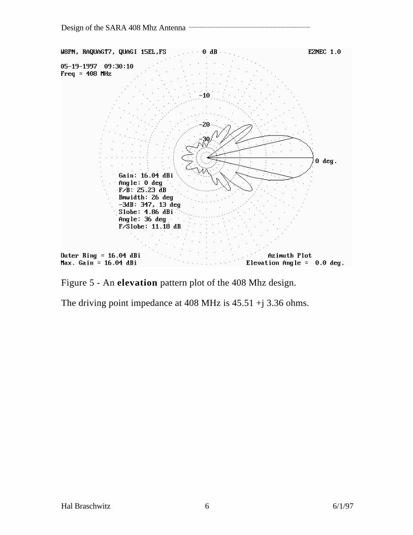
Figure 5 - An elevation pattern plot of the 408 Mhz design.
The driving point impedance at 408 MHz is 45.51 +j 3.36 ohms.

Design of the SARA 408 Mhz Antenna _____________________________________________
Hal Braschwitz 7 6/1/97
Next we modeled this version of the Quagi over average ground whilepointed at the zenith. The lowest element, the loop reflector was located ata height of 61.5 inches above ground. Patterns for this arrangement areshown in Figures 6 and 7.
Figure 6 - An elevation pattern plot of the 408 Mhz design when aimedstraight up!

Design of the SARA 408 Mhz Antenna _____________________________________________
Hal Braschwitz 8 6/1/97
Figure 7 - An elevation pattern plot of the antenna at 400 Mhz whenaimed straight up!
The antenna driving point impedance is almost the same as that shown forthe free space model.
Next this antenna was modeled at increasing angles from the zenith, up to90 degrees, and the patterns were evaluated. The main pencil like beam wasobserved for angles up to 60 degrees from the zenith or up to 30 degreesfrom the horizontal. At angles of more than 60 degrees from the zenith themain antenna pattern beam starts deteriorating and is probably unusable forradio astronomy work.
The input impedance at 400 MHz is 64.15 - j 31.96 ohms. The inputVSWR in a 50 ohm system is 1.836. Further, the input impedance at 410MHz is 39.12 +j 21.48 ohms with a corresponding VSWR of 1.712.

Design of the SARA 408 Mhz Antenna _____________________________________________
Hal Braschwitz 9 6/1/97
Figure 8 - An elevation pattern plot of the antenna at 410 Mhz whenaimed straight up!
We have also modeled designs with larger diameter elements for increasedbandwidth and have studied stacking the basic array both horizontally andvertically for decreased beam widths and increased gain. These results willbe presented in subsequent articles.
Hal Braschwitz
Editors note: I would like to thank Hal and Jim for the fine job ofdeveloping a simple antenna for our members. I evaluated all design databy using the EZNEC program and believe the design to be quite accurate.Jim Carroll has produced working units that have been used successfullywith the SARA 408 MHz receiver. I have prepared a construction articleto show you how to construct the antenna.
Chuck [email protected]

Chuck Forster 1 6/1/97
Constructing the SARA 408 MHz Quagi Antenna
By Chuck Forster
This pictorial guide has been prepared to assist in the physical realizationof the antenna design by Hal Braschwitz and Jim Carroll. Read the paperon this antenna design before constructing the antenna.
The antenna has a wooden boom. You may use fiberglass or any othernon-metallic support as long as the boom remains straight and true. Isuggest a solid wood boom of aspen, oak, pine or similar wood.
After the holes are drilled and before elements are installed, coat the boomand remaining wood parts with several coats of exterior grade varnish oroil based paint. A wood sealer used for decks could be also be used.
The loop reflector, loop driven element and wire directors can all beconstructed using 1/8” diameter brass welding rod. This is available fromany welding supply store or well stocked hardware store. The elementsshould be cut to within +/- 1/16” of the dimensions shown.
The corners of the loop should be bent wire sections with splices along thestraight sides of the loop. Overlap the splice points, wrap with smallcopper wire and solder the entire splice. Clean the brass before solderingand remember to use rosin core “radio-TV” solder, not acid core solder.
The driven element is fed at the center of one of the sides of the loop that isin the same plane as the directors. The driven element is approximately aone-wavelength loop. The fed side determines the E-plane. See ARRLAntenna book, 17th edition, page 5-2. Also review page 18-33 for Quagiconstruction if the book is available to you.
Use 1/4” wood laths to support the reflector and driven element loops. Usetwo laths on the driven element for support of the coaxial cable connection.
Connect the braided shield of the coax to one side of the open loop and thecenter conductor to the other side. Seal the open coax to prevent moisturefrom entering the cable. I suggest using RG-8 or RG-213 (50 ohm coax) ifthe distance between your antenna is greater than 20 ft. Do not run morethan about 100 feet.

Constructing the SARA 408 Mhz Antenna _____________________________________________
C. Forster 2 2/22/98
Remember the sensitivity of the telescope is severely degraded with everyfoot of coax you install. Mount the receiver as close to the antenna aspossible. For distances less than 20 feet consider using RG-8X. This is asmall 50 ohm coax that is available through Radio Shack. The cable has thesame diameter as 75 ohm coax used for cable TV. If all else fails you canuse cable TV coax.
Want to make an interferometer?
Construct two antenna’s. Set them about 50-100 feet apart on an east-westbase line. Aim them both at the same declination, with each pointing duesouth. To each antenna connect an equal length of coax (about 60 ft if theantennas are 100 feet apart).
Combine each end of the coax from the two antennas to a coaxial “Tee”fitting. Connect the tap on the “Tee” fitting to the receiver. Aim theantennas such that that sun will pass directly through the main lobe of thebeam and look for the rise and fall of the interference pattern. The mainlobe of the antenna is directly in line with the boom.
Supporting the antenna near the ground - Danger!
Be sure to protect yourself and others from the sharp ends ofthe director wire elements.
Mount the antenna so it is aimed straight up or at no more than 60 degreesfrom the zenith (at least 30 degrees above the horizon).
The rear (reflector) loop on the antenna can be close to the ground if theantenna is close to vertical. If you need to operate at angles closer to thehorizon, raise the antenna mount so the antenna is at least one boom lengthabove the ground.
Make sure the antenna supports to the side and in front of the antenna arenon-metallic. Antenna supports behind the antenna can be metallic.
It is acceptable to mount the rear of the wood boom onto a metal pipe inorder to extend the antenna above ground.
The remaining construction of the antenna should be self-explanatory. Justremember to keep all elements symmetrical about the boom.

Constructing the SARA 408 Mhz Antenna _____________________________________________
C. Forster 3 2/22/98
The following shows the antenna as viewed from above. This is your guidefor all drillings and mounting details.
116.8"
108.1"
99.4"
90.7"
82.0"73.3"
64.6"
55.9"
47.2"
38.5"
29.8"
23.0"14.0
" 7.5"
Top view of antenna
8" lo
op r
efle
ctor
7.6"
loop
driv
en e
lem
ent
12.5
6" lo
ng d
irect
or
12.0
long
dire
ctor
11.8
long
dire
ctor
11.6
long
dire
ctor
11.4
long
dire
ctor
11.2
long
dire
ctor
11.0
long
dire
ctor
10.8
long
dire
ctor
10.6
long
dire
ctor
10.4
long
dire
ctor
10.2
long
dire
ctor
10.0
long
dire
ctor
12.2
long
dire
ctor

Constructing the SARA 408 Mhz Antenna _____________________________________________
C. Forster 4 2/22/98
The following detail shows the reflector loop construction:
Square loop 8" on each side.Construct with 1/8" brasswelding rod
Reflector Loop Detail
1/4" by 2" wood lath to supportloop wire
Use non-metallic attachments
Screw lath to boom
3/4" x 1.5" wooden boom

Constructing the SARA 408 Mhz Antenna _____________________________________________
C. Forster 5 2/22/98
The driven element loop is as follows:
Driven Element Loop Detail
Loop is opened at midpointand coax is connected. Keepleads as short as practical.Seal end of coax with siliconeseal
Square loop 7.7" on each side.Construct with 1/8" brasswelding rod

Constructing the SARA 408 Mhz Antenna _____________________________________________
C. Forster 6 2/22/98
A side view of the boom shows how to brace the boom with a second pieceof wood if determined to be necessary.
Use Oak, Aspen or other solidboard. Varnish with exteriorvarnish
Wooden Boom Details
Drill holes and fasten wireelement with epoxy glue
Add 3/4" by 1.5" "Tee" cap onboom member to increaserigidity of the boom if required.Any non-metallic or non-
conductive material can beused for the boomconstrcution and loop support.
Have a good time building your antenna.
Chuck [email protected]

DRAWING NUMBER:
SARA-408-
408 Mhz Radio Telescope
Engineering Design: Jim Carroll
Development: C. Forster
Society of Amateur Radio Astronomers HAa
LATEST REVISION: 10/15/98Hinks and Kinks
The RF and IF section of the receiver is constructed with double sided copper PCB boards. The top or component side is used as a shield between circuit stages. After the hole is drilled for the component lead, use a larger drill, about a 1/8 inch, to route the copper away from the hole the component lead passes thru.
Use a new sharp drill and do this by hand! You will drill through the PCB if you use a power tool and then ruin the project.
Make sure you identify all the "Z" wire locations where a bare wire is soldered on the top and bottom of the circuit board. DO NOT cut back the copper at these locations.
"Z" wire location

408 MHz Receiver
Antenna
Power
Pre-Regulator
Red Power
Ground Black
TemperatureStabilizer
Heater
Red
Sensor
Temp green
Temp
PowerSupply
Remote Tune
Tune
yellow
Post-Processor
+10V
+5V
Ground
+ Input _
orange
white
SignalGnd Out
+11V +12V
Ground
+12-13.8V
Power
Amplifier Out to Recorder
Amp OutSpeaker
Gnd
+12V
Gnd
+12V
Gnd
+12V +5V
+10V
Gnd
RXb-408 MHz Radio Telescope ReceiverBlock Diagram
Gnd
Over tempThermostat
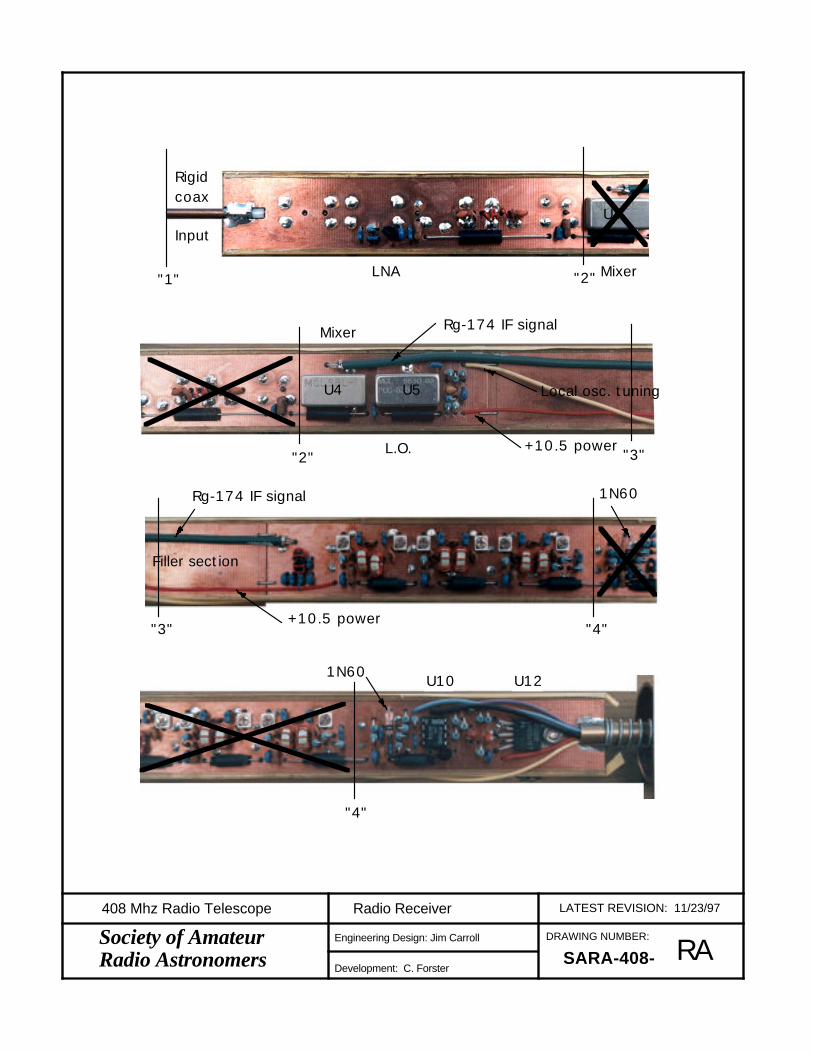
U4 U5
Rg-174 IF signal
Local osc. tuning
+10.5 power
Mixer
L.O."2" "3"
Rigidcoax
InputU4
LNA Mixer"1" "2"
1N60U10 U12
"4"
1N60Rg-174 IF signal
+10.5 power
Filler section
"3" "4"
RA
LATEST REVISION: 11/23/97Radio Receiver
DRAWING NUMBER:
SARA-408-
408 Mhz Radio Telescope
Engineering Design: Jim Carroll
Development: C. Forster
Society of Amateur Radio Astronomers

U2U3U3U3
"C""D"
U3 U2
"B""C"
Rigidcoax
Input
Q1U2U3"A""B"
RBb
LATEST REVISION: 8/28/98Radio Receiver
"D"
DRAWING NUMBER:
SARA-408-
408 Mhz Radio Telescope
Engineering Design: Jim Carroll
Development: C. Forster
Society of Amateur Radio Astronomers

Look
ing
at f
oil(
wiri
ng)
Side
40
8RT
5IF
A/D
ETD
CA
/REG
SARA
10
/24
/96
7.100"
1.000"
Look
ing
at f
oil(w
iring
) si
de
40
8RT
5LN
A/M
IX/L
O
11
/24
/97
6.8
00
"
1.000"
SARA
RC
LATEST REVISION: 11/23/97Radio Receiver
DRAWING NUMBER:
SARA-408-
408 Mhz Radio Telescope
Engineering Design: Jim Carroll
Development: C. Forster
Society of Amateur Radio Astronomers
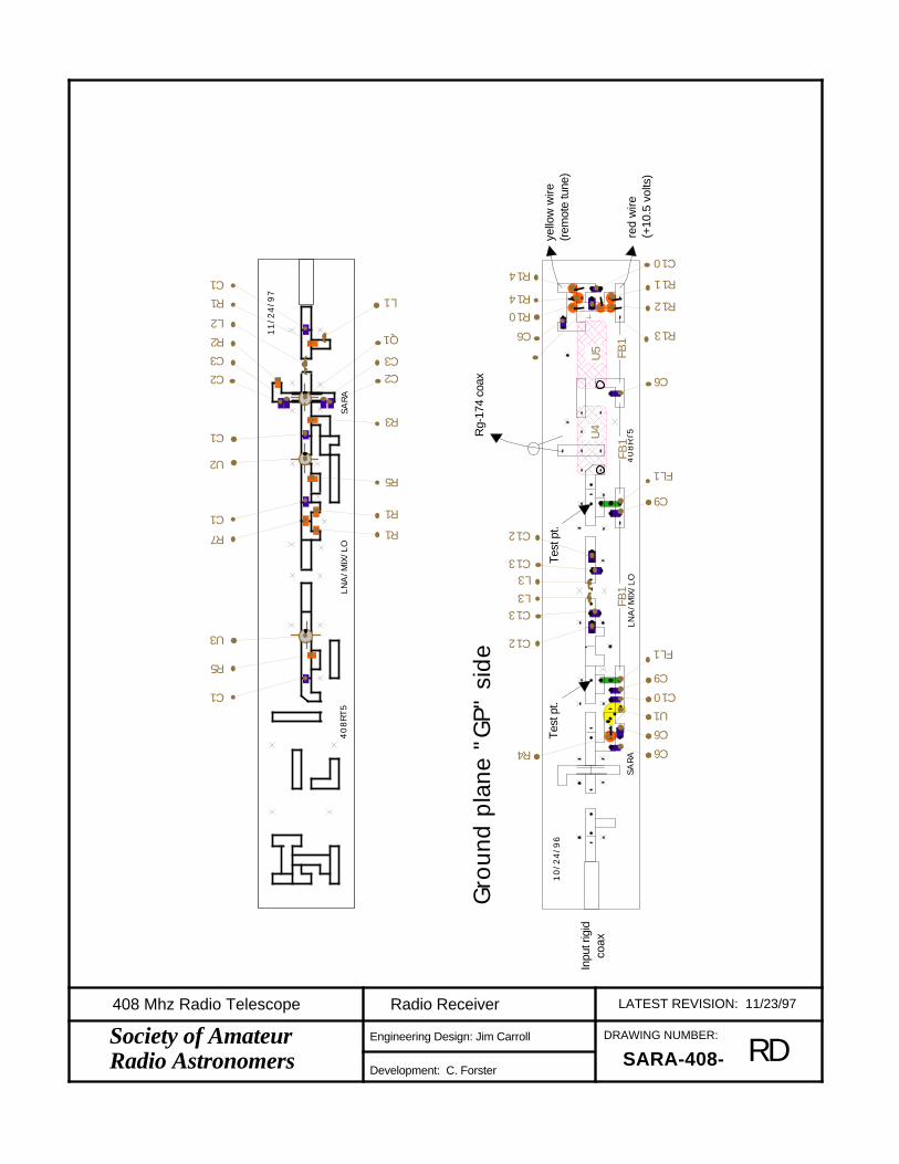
40
8RT
5LN
A/M
IX/L
O
11
/24
/97
SARA
C1
R5
U3
R7
C1
U2
C1
C2
C3
R2
L2
R1
C1
R3
C2C3
Q1
R5
L1
R1
R1re
d w
ire(+
10.5
vol
ts)
yello
w w
ire(r
emot
e tu
ne)
Rg-
174
coax
Tes
t pt.
Tes
t pt.
Inpu
t rig
idco
ax
40
8RT
5LN
A/M
IX/L
O
10
/24
/96
SARA
Gro
und
plan
e "G
P" s
ide
C12
C13
U1
C10
C9
FL1
R4
C13
C12
L3L3
FB1
C9
FL1
FB1
FB1
U4
U5
C6
R13
R11
R12
C10
R10
C6
R14
R14
C6
C6
RD
LATEST REVISION: 11/23/97Radio Receiver
DRAWING NUMBER:
SARA-408-
408 Mhz Radio Telescope
Engineering Design: Jim Carroll
Development: C. Forster
Society of Amateur Radio Astronomers

Gro
und
plan
e "G
P" s
ide
Green wire
Rg-
174
coax
Red wire
Red
wire
Black wire
Orange wire
Whi
te w
ire
L5 C6
C10
C30
FL3
R16
FB
1
C24
C23
C24
C23
C31C32C31
C13
C30
R16
C31
C32C31
C13
C30
C31C32C31
C13
C13
C13
C30C13
C6
C10FL3
C10FL3
C10FL3
R16
(2)L
6(2
)L6
(2)L
6
FB
1F
B1
R19
R20 R
21
FB
1
R16,R23
C6D1
C6
R26
R28
R14
R24
R25
C6
U10 U
11
U12
R29
R28
R11
R26
R34
R11
C58
C20 C57+
R19
=~10
0
R20
=~
68R
21=~
100
+
U3
U3
U3
U2
Look
ing
at f
oil(
wiri
ng)
Side
40
8RT
5IF
A/D
ETD
CA
/REG
SARA
10
/24
/96
7.100"
1.000"
RE
LATEST REVISION: 11/23/97Radio Receiver
DRAWING NUMBER:
SARA-408-
408 Mhz Radio Telescope
Engineering Design: Jim Carroll
Development: C. Forster
Society of Amateur Radio Astronomers

-------| || || || | -------
-------| || || || | -------
-------| || || || | -------
-------| || || || | -------
-------| || || || | -------
-------| || || || | -------
FS 9dB pad4
8
7
5
6
32 1
Select R12 for340MHz at 5V
70MHz IF
FL1 FL2 FL3
FL4Adjust for 10.5V out
FL6FL5
10.5V
408MHzInput
Mixer
Audio to Post Processor
M
To Temp Controller 100mV/C
408MHz Radio Telescope Receiver- RFbC57100n
C5822uF
C36
10n
FB5
C42
3.5-10p
C41
27p
L9
130n
L8
130n
C402p
C376.8p
C39
27p
C38
3.5-10p
FB
FB
MAR-1U7
10n
MAR-1U8
C436.8p
+12V
C591uF
TEMPOUT
RXOUT
C561n
C551n
FB
FB10n
C521n
C53
10n
FB7
C541n
MAR-1U9
C516.8p
C50
3.5-10p
C49
27p
L11
130n
L10
130n
C482p
C47
27p
C44
10n
FB6
C456.8p
C46
3.5-10p
FB
FB10n
D11N60
U10ALMC662
Out
+Vs
U11LM35DZ +
U10B
OffInOut
Adj
U12LM2941CT
REMTUNE
C21
10nC191n
C20
1uF
C28
10n
C18
1n
FB3 FB4
C356.8p
C34
3.5-10p
C33
27p
L7
130n
L6
130n
C322p
C296.8p
C31
27p
C30
3.5-10p
C25
22p
C24
22p
C23
68p
FB
FB
MAR-6U6
10n
TPC271n
C26
68p
FB
FB
FB
MAR-6U3
FB2
C16
100p
C17120p
100p
TPC153p
C14
6.8p
L4L3C13
6.8p
C123p
100p
C10
10n
C9
100p
TPC11
120p
C7
1n
C6
1n
C5
10n
C4
1n
C1120p L2
L1220n
Q1ATF-21186
C2
10n
C3
1n
C8120p
IN
COM
OUT
U178L05
RFLO
GND
IF
U4 SBL1
FB1
U2MAR-6
FB
L590n
VccTune
LOPOS535
R17332
R331k
R34
R326.8k
R31
237
R29
61.9k
R306.8k
R28
237
R27
100k
R261kR24
1M
R2510k
R2346.4R21R19
R22332
R18332
R20
R15
100k
R13
2.2k
R1042.2k
R12
R116.8k
R16332
R9330
R768
R8100
R6100
R5330
R410
R3150
R2
47
R1100
R14100k

+12 to +13.8V
Adjust R3 for 11V out
Receiver Power Supply Pre-Regulator
mounted on terminal strip outside heated tube- RGb
C20.47uF
C122uF
To Rcvr +V Off
InOutAdj
U1LM2941CT
R21k
R3
R16.8k

DRAWING NUMBER:
SARA-408-
408 Mhz Radio Telescope
Engineering Design: Jim Carroll
Development: C. Forster
Society of Amateur Radio Astronomers PAa
LATEST REVISION: 12/8/97Post-Processor

DRAWING NUMBER:
SARA-408-
408 Mhz Radio Telescope
Engineering Design: Jim Carroll
Development: C. Forster
Society of Amateur Radio Astronomers PBa
LATEST REVISION: 12/8/97Post-Processor

DRAWING NUMBER:
SARA-408-
408 Mhz Radio Telescope
Engineering Design: Jim Carroll
Development: C. Forster
Society of Amateur Radio Astronomers PCa
LATEST REVISION: 11/8/98Post-Processor
4.00"
Caution:Artwork may not be to scale. Adjust so 4.0" is exactly 4.0"

DRAWING NUMBER:
SARA-408-
408 Mhz Radio Telescope
Engineering Design: Jim Carroll
Development: C. Forster
Society of Amateur Radio Astronomers PDa
LATEST REVISION: 11/8/98Post-Processor
+
+
+
+
+
+
++
+12
Rem Tune
PwrGrd
Spkr
VcoG4
Out2
Pot's
VF2OS-OSGrd
OS-C OS-FG100 GC
LIMVF1Out1
LPF-CLPF-1+IN
LPF-16
-IN
U8
U6
U5U4
U7
U3U2U1
+
+
+
+
+
+
+
+
U8
U6
U5U4
U7
U3U2U1
R1C1
R4
C2
R2
R5
C6
D2
R10
C3 R7
R8
D1
R11
R12
R9
C4
C5
R3
R17
R18
R15
R16
R19
R20
R29
R27 R28
R21
R26
R22
R25
D3
C8
C7
R23
R24
R31
R32
C14
C16
C15
C11
C12
C10
C13
C9
D4D5
C17
R6
Resistor 1/10 watt with leads
Capacitor with leads
Bus power filter
Capacitor-chip type
Resistor-chip type
Legend
Inductor
Toroid coil
Diode
Capacitor-adjustable
TO-? case device
Z-wire
Device

408 MHz Radio Telescope ReceiverPost Dection Pre-processor- PEb
6
47
VCO out
VCO
AMP Audio Sel
COARSEFINEOFFSET
FS
FS
Limiter
out
in
Signal In
Signal Gnd1
23
756
2
3
1
7
5
6
16 14
11
3 5 8 6 7
4
92
35
5
67
2
3
1
+
+ Time Const Sec 1 4 16
Amp Out 1 Gain 100 20 4
+10V
C7 10nC8
220n
S4
+10V
D31N4148
R3010K
C947uF
SPKROUT U5LM386 C10
220uF
AMPOUT2
S3
U3B
-5 V
R1410K
U3ALF442
C3220n
C5
4.32u
C4
1.5u
U2B
LF442
D1
1N4148
S1
U2A
C647uF
IN-
C21n
U1A
IN+
C11n
U1BLF442
D2
1N4148
S2
R1310K
U4
4046
R24
R23100k
R26
1k
R25100k
R27
R2910k
R28100k
R22
4.99k
R21
20.5k
R20
4.02k
R19
1k
R17
100k
R16
1M
R15
51.1k
R18
169k
R12150k
R11
24.9k
R9
2M
R8
680k
R7
4.64k
R5
75k
R675k
R4
10k
R10
100k
R2
75k
R375k
R1
10k

408 MHz Radio Telescope ReceiverPost Dection Pre-processor Power Supplies- PFb
to receiver
Tune1
4
8
5
Off
On
REMTUNE
+10V
-5 V
+
C174.7uF
+C15
4.7uF
+12V
+12V In
IN
COM
OUT
U679L05
IN
COM
OUT
U8LM2940T-10
C14
1nF
C13100nF
+
C114.7uF
+
C12220uF
+
C164.7uF
GndTrgOutRst Ctl
ThrDisVcc
U7555
D4
1N4001
D51N4001
R3310k
R314.64k
R32100k

DRAWING NUMBER:
SARA-408-
408 Mhz Radio Telescope
Engineering Design: Jim Carroll
Development: C. Forster
Society of Amateur Radio Astronomers PHb
LATEST REVISION: 9/19/98Post-Processor Panel
+12VOUT
PWRGRD
REMTUNE
SIGGND
RECIN
TEMPIN
+12VIN
PWRGRD
AMPOUT1
AMPOUT2
TEMPOUT
VCOOUT
SPKROUT
SPLRGRD
1641
100204
IN
OUT
AMP
VCO
TC-SEC
GAIN
RC LPF
DC AMP
COURSE
FINE
OFFSET
OFFSET TUNE VOLUME
Post DetectionPre-Processor
LIM
AUDIO
POWER ON OFF
This front panel overlay is designed to be installed on a Radio Shack model 270-1807 construction cabinet. As of 9/98 this was claimed to be the new version of an enclosure offered by Radio Shack.
The box comes with a plastic and an aluminum cover. Apply spray dry contact adhesive on the cover and on the back of the paper panel layout. Do not get excessive adhesive on the paper or it will bleed through.
When dry, carefully place the paper front panel on the box cover and then add a layer of clear protective overlay available at office supply centers for laminating a sheet of paper.
Drill holes carefully to prevent tearing front panel paper.
5"Make sure this line is 5" on your printout

DRAWING NUMBER:
SARA-408-
408 Mhz Radio Telescope
Engineering Design: Jim Carroll
Development: C. Forster
Society of Amateur Radio Astronomers PIa
LATEST REVISION: 12/8/97Post-Processor

DRAWING NUMBER:
SARA-408-
408 Mhz Radio Telescope
Engineering Design: Jim Carroll
Development: C. Forster
Society of Amateur Radio Astronomers PJa
LATEST REVISION: 12/8/97Post-Processor
6
5
7
4
4
78
5
6
5
3
2
HOT
REG
COLD
2
3
---------------------------| || || || || || || || || Oven | ---------------------------
18
From heater sensor To heater winding
8
5
6 7
4
OVER TEMP
D1-D4 1N4148
408 MHz Receiver Housing Temperature Stabilizer -SEbFrom Receiver 100mV/C
C5100n
+5V
+5V
C4100n
Temp In
D2
D1
DS1
D3
+
U5ALM358
Heat er
Heat er
Sensor -
Sensor +
Q2
IRF541
+
U1B
C2 1uF
R1010K
+
U1ATLC27L2
Out
+Vs
U2LM35DZ
IN
COM
OUTU4
78L05
C3
47uF
+
U6A
DS4
DS3
DS2
+12V
U6B LM358
C147uF
IN
COM
OUTU3
78L05
Q1IRF541
R51K
Q32N2907
Q4
2N2222
D4
R1610k
R1590.9k
R1310k
R171k
R1975k
R1875k
R2142.2k
R2042.2k
R12 1M
R1410k
R8220 R11
1MR96.81k
R65.11k
R45.11k
R3200
R710k
R210k
R190.9k
R24100k
R23
100k
R22
100k
R27
1.78k
R26
1.78k
R25
1.78k

12 10 8 6 4 2
Sense -
Sense +
Htr-
Htr+
Thermo-stat {
Sense -
Sense +
Htr-
Htr+
To T
emp.
Cont
rolle
rTo
Hou
sing
To R
ecv.
Pwr Grd
+11 Vdc
Sig. Grd.
Rec Out
Temp Out
Tune
Pwr Grd
+12 Vdc
Sig. Grd.
Rec Out
Temp Out
Tune
.47uf
To P
ost
Pro
cess
or
To R
ecei
ver
Out
In
Grd
Pre-Regulator
Shielded Cable
IAa
LATEST REVISION: 11/23/97Interconnection Diagram
DRAWING NUMBER:
SARA-408-
408 Mhz Radio Telescope
Engineering Design: Jim Carroll
Development: C. Forster
Society of Amateur Radio Astronomers

SARA Construction Notes 1 7/20/01
SARA 408 MHz Receiver Kit
This set of notes is an attempt to answer in advance, some ofthe questions I have received on the SARA 408 MHz radiotelescope kit.
What does the kit cost?As of 2001 the “kit” price is estimated at $300 assumingparts are purchased in lots of 20 units. The price includesthe radio unit, the post processor, but not the temperaturestabilizer or antenna parts. SARA is not offering kits atthis time, but if you are interested let me know. If enoughpeople are interested I would consider putting the kitstogether again. If anyone would like to do this please letme know.
Where to get informationReview the manuals available from RAInfo.net.
About this projectThe following is not intended to deter you, but make sure youare not going to start a project and find out later it wasmore than you wanted to deal with.
Completeness of the kitThe manuals are in a constant state of development. Theywill be expanded as questions from builders are presented.
What you will needIf you have not assembled electronic kits or performed RFconstruction before, this may be a difficult project. Do youhave a technical friend to help? You will be solderingleadless components and a controlled temperature solderingstation with micro tips will be required.
You will need a Dremel hobby drill and small printed circuitboard drills. The printed circuit boards need to be trimmedto size and drilled. DO NOT FORGET TO HAND ROUTE CLEARANCEHOLES ON THE GROUND PLANE SIDE OF THE RF AND IF circuitboards. If you do not know what I am talking about, ask me.
The circuit boards are hand etched in my basement, providingreasonable quality pc boards, more than adequate for theproject. The board traces are intentionally larger thanprofessional circuit boards to allow more chance for survivalat the hands of a builder with too large of a soldering iron.
The kits are not complete. Items such as PVC conduit, 1 inchcopper pipe, magnet wire, foam insulation, cabinets and knobsare not included. Parts for the post processor are included.The Temperature Stabilizer is not included.

SARA Construction Notes 2 7/20/01
You will have to construct your own antenna system. See theSARA 408 MHz antenna construction articles.
Getting the manualsThe manuals are about 5 megabytes at this time and will begetting larger, can you accept email of this size?
You will need Adobe Acrobat Reader 4.0 or later to view themanuals. Windows 95 or a Mac system with at least“thousands” of colors is required to see the photo’s incolor. Another option is to print the documents with a B/Wlaser printer set for color/grayscale mode.
The Acrobat Reader can be downloaded free from www.adobe.com
What if you have problems?I offered to tune the finished radio and make minor repairsfor $40 per unit. This assumes you have not injuredexpensive components in the kit. The $40 includes returnshipping via UPS. The $40 charge is an estimate and may belowered if minimal work is required.
What if you need replacement parts?Some of the parts have minimum orders that make ordering asingle unit prohibitive. Contact me before orderingreplacement parts. Since this is a zero profit project, Ican not maintain a significant stock of repair parts. Themanual lists web sites of the parts suppliers we used. Mostof them will mail you a catalog if you leave them an emailnote on their web site.
Are kits always available?No, but if I can get deposits on groups of 20 kits inadvance, I will order the parts that most people would finddifficult to accomplish on a single unit basis.
Chuck Forster

Addendum1 1 7/20/01
Misc. comments:
Z wire is a term for a bare wire that is soldered to the board onboth sides. This "couples" the copper ground plane from one sideof the board to the other. If we had plated thru holes we wouldnot need this.
The rails only have to go for about 3 inches on each side of thePCBjoints. The RX have three PCB's, the center section is a blank.You need to file one side of the rectangular tubing off so itbecomes a "C" channel.
Yes cut out the PCB for the input hardline and a small section forthe brass tubing at the end.