society of motion picture and television engineers european broadcasting union task force for
TRANSCRIPT

Society of Motion Picture and Television Engineers
European Broadcasting Union
Task Force for Harmonized Standards for the Exchange of ProgramMaterial as Bitstreams
Final Report:Analyses and Results
July 1998

Copyright © 1998 of the European Broadcasting Union (EBU) and the Society of Motion Picture and TelevisionEngineers, Inc. (SMPTE).
All rights reserved.
No part of this publication may be reproduced, stored in a retrieval system, or transmitted in any form or by anymeans – electronic, mechanical, photocopying, recording, or otherwise – without the prior written permission ofone of the copyright holders.
Edited and laid out by EBU Technical Review on behalf of the EBU / SMPTE Task Force for HarmonizedStandards for the Exchange of Program Material as Bitstreams.

Page i
Contents
Preface 1
Executive summary 3Systems summary 4
Compression summary 4
Wrappers and Metadata summary 6
Networks and Transfer Protocols summary 6
1. Introduction 8
2. Systems 112.1. Introduction 11
2.1.1. Systems of the future will do different things 11
2.1.2. Systems of the future will be quite different 12
2.1.3. New workflows will result from integrated control schemes 12
2.1.4. New types of system design are required 12
2.2. Request for Technology 13
2.3. Object model 14
2.3.1. Why object-oriented technology? 15
2.4. System model 15
2.4.1. Structure of the model 15
2.4.2. Activities 162.4.2.1. Pre-production 172.4.2.2. Acquisition & Production 172.4.2.3. Post-production 172.4.2.4. Distribution 172.4.2.5. Storage 172.4.2.6. Transmission & Emission 172.4.2.7. Archiving 17
2.4.3. Planes 182.4.3.1. Video Essence 182.4.3.2. Audio Essence 182.4.3.3. Data Essence 182.4.3.4. Metadata 18
2.4.4. Layers 192.4.4.1. Application layer 192.4.4.2. Network layer 192.4.4.3. Data Link layer 192.4.4.4. Physical layer 20
2.4.5. Control and Monitoring plane 20
2.5. Operations 20
2.5.1. Control 202.5.1.1. Strategic 20

Page ii
2.5.1.2. Tactical 212.5.1.3. Peer-to-peer 212.5.1.4. Resource management 212.5.1.5. Physical control network issues 212.5.1.6. Multiple forms of implementation 22
2.5.1.6.1. Hierarchical 22
2.5.1.6.2. Peer-to-peer 222.5.1.7. Essential characteristics 222.5.1.8. Logical control layers 23
2.5.1.8.1. Transaction-based control protocols 23
2.5.1.8.2. Functional APIs 23
2.5.1.8.3. Transition to object-oriented studio control by means of proxies 23
2.5.2. Monitoring, diagnostics & fault tolerance 242.5.2.1. Feedback 242.5.2.2. Failure prediction 252.5.2.3. On-line / Off-line diagnostics 252.5.2.4. Fault tolerance 25
2.5.2.4.1. Redundancy 25
2.5.2.4.2. Segmentation 25
2.5.2.4.3. Monitoring and verification 25
2.5.2.4.4. Implementation 262.5.2.5. Content integrity 26
2.5.3. Data Essence and Metadata management 262.5.3.1. Layered model 272.5.3.2. File transfer 272.5.3.3. Streaming 272.5.3.4. Data Essence 27
2.5.3.4.1. Repetition rate of Data Essence 28
2.5.3.4.2. Registration of Data Essence types 282.5.3.5. Metadata 28
2.5.3.5.1. Layered structure 28
2.5.3.5.2. Minimum repetition rate of Metadata types 28
2.5.3.5.3. Registration of Metadata types 292.5.3.6. Permanence of Data Essence and Metadata 292.5.3.7. Data Essence / Metadata capabilities 29
2.5.3.7.1. Capability in storage systems 29
2.5.3.7.2. Capability in transport systems 30
2.5.3.7.3. Videotape storage 30
2.5.3.7.4. Datatape storage 31
2.5.3.7.5. Disk storage 31
2.5.4. Content multiplexing 31
2.5.5. Multiplexing of Essence into containers 322.5.5.1. Transferring Essence between multiplexes 332.5.5.2. How to deal with opportunistic data over transports 33

Page iii
2.5.5.3. Multiplexing of different systems / formats 332.5.5.4. Statistical multiplexing considerations 33
2.5.6. Timing, synchronization and spatial alignment 342.5.6.1. Reference signals 342.5.6.2. Absolute time reference 342.5.6.3. Temporal alignment 342.5.6.4. Timing constraints on compressed signals 342.5.6.5. Latency and delay 352.5.6.6. Spatial alignment 352.5.6.7. Hybrid analog / digital facilities 35
2.6. Interconnection options 35
2.6.1. Development of templates 36
2.6.2. Transfer definitions 36
2.6.3. Hard real-time 362.6.3.1. Play-to-air 36
2.6.3.1.1. Video 36
2.6.3.1.2. Audio 37
2.6.3.1.3. Data Essence and Metadata 37
2.6.3.1.4. Control 372.6.3.2. Live-to-air 372.6.3.3. Live recording 37
2.6.4. Soft real-time 372.6.4.1. Video and Audio (uncompressed) 372.6.4.2. Video and Audio (compressed) 372.6.4.3. Data Essence and Metadata 382.6.4.4. Control 38
2.6.5. Non real-time 382.6.5.1. File transfers 382.6.5.2. Control 382.6.5.3. Streaming 38
2.7. Migration 39
2.7.1. Placement of existing protocols into the public domain 39
2.7.2. Essential Common Protocols 39
2.7.3. Interoperability between old and new systems 39
2.8. Economic model 39
2.9. Standards 40
2.9.1. Work under way in the SMPTE 40
2.9.2. Standardization efforts yet to be undertaken 40
2.9.3. Summary of standards required 41
2.10. References 41
2.10.1. Object-oriented technologies 41
3. Compression issues 433.1. Introduction 43
3.2. Image quality 44
Page iv
3.2.1. Coding method 44
3.2.2. Sampling structure – SDTV 44
3.2.3. Compression pre-processing 45
3.2.4. Video data-rate – SDTV 46
3.2.5. MPEG Group of Pictures 46
3.2.6. Constant quality vs. constant data-rate 473.2.6.1. Constant quality (VBR) systems 473.2.6.2. Constant bit-rate (CBR) systems 473.2.6.3. Interfacing VBR and CBR environments 47
3.2.7. Editing 47
3.2.8. Concatenated compression 48
3.3. Quality levels 49
3.4. Operational considerations 50
3.4.1. Working with existing compression families 51
3.4.2. Agile decoders 51
3.4.3. Native decoders 51
3.5. Family relations 52
3.5.1. Tools available for intra-family transcoding 52
3.5.2. Compatible intra-family record / replay 52
3.5.3. MPEG at 24 frames-per-second rates 52
3.6. Interfaces 52
3.6.1. Status of interfaces for MPEG-2 and for DV / DV-based compression 52
3.7. Storage 53
3.7.1. Data-rate requirements 53
3.7.2. Resource management 53
3.7.3. Audio, Video and Metadata synchronization 53
3.7.4. VTR emulation 53
3.8. Interoperability 53
3.9. Compliance testing 54
3.9.1. Test equipment 54
3.10. HDTV issues 54
3.11. Audio compression 55
3.11.1. Studio operations 55
3.11.2. Compression issues 563.11.2.1. Multi-stage encoding and decoding 563.11.2.2. Coding frame structure 563.11.2.3. Latency issues 563.11.2.4. Mixing 56
3.11.3. Use of Audio compression 573.11.3.1. Contribution 573.11.3.2. Distribution 573.11.3.3. Emission 573.11.3.4. Archiving 57
3.11.4. Channel requirements 57

Page v
3.11.4.1. Mono 573.11.4.2. Stereo 583.11.4.3. The 5.1 format 583.11.4.4. Recording of the 5.1 format on professional videotape recorders 58
3.12. Compression issues: recommendations and current status 58
4. Wrappers and Metadata 614.1. Introduction 61
4.2. Purpose of Wrappers 61
4.3. Overall concepts - terminology and structure 62
4.3.1. General 62
4.3.2. Storage, Streaming, File Transfer and editing of Content 62
4.3.3. Content structure 63
4.3.4. Essence 65
4.3.5. Metadata 66
4.3.6. Metadata characteristics 66
4.3.7. Overhead 67
4.3.8. Metadata Sets 67
4.4. General requirements 68
4.4.1. Wrapper requirements 684.4.1.1. Size of wrapped Content 684.4.1.2. Platform neutrality 684.4.1.3. Immutability and generation numbering 684.4.1.4. History 684.4.1.5. Support of transactions 684.4.1.6. Property rights 684.4.1.7. Compatibility and conversion 694.4.1.8. Extensibility 694.4.1.9. Other requirements 69
4.4.2. APIs 70
4.4.3. Breadth of application and Wrapper profiles 70
4.4.4. Framework of a solution 71
4.5. Metadata requirements 72
4.5.1. Metadata vision 72
4.5.2. Requirements for Metadata standards 724.5.2.1. Class rules 73
4.5.2.1.1. Classes 0-7: publicly-defined and due-process Standardized (a.k.a. Registered) 73
4.5.2.1.2. Class 8: registered as private with public description 73
4.5.2.1.3. Class 9: unpublished with no public description (user-defined, proprietary orexperimental) 73
4.5.3. Registry 734.5.3.1. Registration Authority activities 74
4.5.4. Metadata Templates 744.5.4.1. Production planning 744.5.4.2. Acquisition and playback 74

Page vi
4.5.4.3. Editing and mixing 744.5.4.4. Storage of consolidated programs 754.5.4.5. Emission 754.5.4.6. Archiving 75
4.6. Unique Material Identifiers 75
4.6.1. Standard UMID Core 76
4.6.2. UMIDs as a linkage between Streams and Databases 77
4.6.3. The UMID Core in Streaming applications 77
4.7. Wrapper formats 78
4.7.1. First Request for Technology 78
4.7.2. Storage Mechanism and Second Request for Technology 78
4.7.3. Interoperability of Wrapper formats 79
4.7.4. Interchange 79
4.7.5. Streaming and Storage Wrappers 80
4.7.6. Repetition rates of Vital Metadata 80
4.7.7. Streaming Wrapper formats 81
4.7.8. Storage Wrapper formats 814.7.8.1. Wrapper varieties 824.7.8.2. Interchange Storage Wrapper format 834.7.8.3. Content repertoire 834.7.8.4. Data model 84
4.8. Newly-identified work 84
4.8.1. Interchange Storage Wrapper 84
4.8.2. Wrapper profiles and Content repertoires 84
4.8.3. Metadata Sets 84
4.8.4. Essence format documentation 85
4.8.5. Mapping onto transport mechanisms 85
4.9. Conclusions 85
4.9.1. Work in progress 85
4.9.2. Which documents to hand over 86
4.9.3. Note on proprietary technology 86
5. Networks and Transfer Protocols 875.1. Introduction 87
5.1.1. File transfer and streaming 87
5.1.2. Quality of Service considerations 87
5.1.3. Reference Architecture 88
5.2. File transfer methods 88
5.3. Streaming methods 89
5.4. Recommended transport systems for Content 90
5.4.1. Serial Data Transport Interface (SDTI) 91
5.4.2. ATM 915.4.2.1. File transfer over ATM 91
5.4.3. Fibre Channel 92

Page vii
5.4.3.1. File transfers over Fibre Channel 925.4.3.2. Streaming over Fibre Channel 92
5.4.4. IEEE 1394-1995 high-performance serial bus 925.4.4.1. File transfers over IEEE 1394 935.4.4.2. Streaming over IEEE 1394 93
5.5. Other transport systems 93
5.6. Bridging and Tunneling 93
5.7. Recommendations for future work 93
5.7.1. File transfers 93
5.7.2. Streaming / mapping 94
5.7.3. Standards for mapping the Content / containers into transport mechanisms 94
5.7.4. Interfaces / networks 95
Annex A:Abbreviations and specialized terms (Glossary) 97
Annex B:Systems 110
B.1. Object model tutorial 110
B.2. The RFT: New systems management services 114
Annex C:Networked Television Production – Compression issues 129
C.1. Introduction 129
C.2. Compression families for networked television production 131
C.3. Requirements for networked operation 132
C.4. Television production based on DV compression 135
C.5. Television production based on MPEG-2 4:2:2P@ML compression 148
C.6. Supplement A: EBU Statement D79-1996 – Open standards for interfaces forcompressed television signals 162
C.7. Supplement B: EBU Statement D80-1996 – Compression in television programmeproduction 163
Annex D:Wrappers and Metadata 165
D.1. First Request for Technology 165
D.2. Second Request for Technology 166
D.3. Responses to the Requests for Technology 169
D.4. Related Essence format documents 171
Annex E:Networks and Transfer Protocols - Reference Architecture for Content Transferand Streaming 173
Page viii
E.1. Introduction 173
E.2. File transfer and access protocols 174
E.3. Streaming 194
Annex F: Acknowledgments 204
Annex G: Task Force participants 205

Page 1
PrefacePrefaceThe long-heralded convergence of television, computer and communications technologies is happening. The paceof change in the television industry, as a result of this convergence, is quickening dramatically as countries aroundthe world make commitments to digital television broadcasting in one form or another. The result is the creation ofmany new, competitive, distribution channels that are driving a constantly-growing consumer demand forprogramming. Meeting that demand, in turn, requires a leveraging of the technologies used in digital signalprocessing, computers and data networking in order to yield significantly-enhanced creativity, improved efficiency,and economies of scale in the origination and dissemination of Content. The result of these changes is likely tolead to the wholesale replacement, or new construction, of practically all the television production and distributionfacilities world-wide over the next decade or so. A major migration and a huge investment in technology is highlyprobable, and thus it is critical that the right decisions are made about the technological choices and themanagement of the transition to the new forms.
The opportunities presented by such a concurrent, world-wide, renovation of facilities are unique in the history ofthe industries involved. The coming changes will result in the industries literally remaking themselves, withconsequent possibilities for new workflows, system designs and cost structures. Indeed, with the proliferation ofdistribution channels to audiences will come a fragmentation of those audiences which will mean that smallerbudgets will be available for specific productions. The only ways to counteract this effect will be to find more usesfor the Content produced, or to find more efficient ways in which to produce it.
With these necessities firmly in mind, the European Broadcasting Union (EBU) and the Society of Motion Pictureand Television Engineers (SMPTE) formed a joint Task Force for the Harmonization of Standards for theExchange of Programme Material as Bitstreams. The Task Force was charged with two assignments: (i) to producea blueprint for the implementation of the new technologies, looking forward a decade or more, and (ii) to make aseries of fundamental decisions that will lead to standards which will support the vision of future systems embodiedin the blueprint. The first of these assignments was completed in the Task Force’s First Report — UserRequirements, published in April 1997.
The extraordinary document that you hold in your hands – or see on the screen in front of you – is the Task Force’sresponse to the second assignment. It was produced by a group of over 200 experts from Europe, Japan, Australiaand North America, meeting some seventeen times over a period of 1½ years. It is intended as a guide, developedco-operatively by the several industries involved, and will set the direction for all to follow. It represents theculmination of a unique effort by those industries – recognizing that they stand at a crossroads in their collectivehistories – to look into the future jointly and to choose their course together. It takes as its premise the need toidentify requirements for the development of standards that will enable the exchange of programme material in thenew forms and which will support the construction of complete systems based upon the new techniques. It includesthe views of users and manufacturers of all types, both of which are needed in order to get an idea of what shouldand what will be implemented, and how it can be done.
At the start of this activity, some saw it as an opportunity to select a single video compression scheme to be used ata moderate bit-rate for a wide range of production and post-production applications. After thorough discussion,however, it was recognized that such a goal was not realistically achievable. Because of the many trade-offs thatexist between compression methods, their parameters, and the performance achieved in specific situations, differenttechniques will be required in particular situations to meet explicit requirements. Thus the greatest benefit to allconcerned will come from providing the mechanisms that will permit systems to handle easily the variouscompression schemes, while maintaining the maximum quality of the programme elements.
To this end, significant progress has been made in identifying the structures that will be necessary to supporttelevision production using compression, and in initially defining their characteristics. Among these are a newclass of programme-related data called Metadata and, for the control and management of systems, the use of objectmodeling techniques. Metadata may be defined as the descriptive and supporting data that is connected to the
Page 2
programme or the programme elements. It is intended both to aid directly the use of programme Content and tosupport the retrieval of Content as needed during the post-production process. Object modeling techniques treat thedevices and the Content items as “objects,” the properties and parameters of which can be manipulated. Objectmodels are intended to enable the easy integration of new devices into control networks, and the control of thosedevices from unified control and management systems.
Although the work of the Task Force is over, it is not done. Rather it has just begun. The purpose of the TaskForce all along has been to point the way for successor activities to develop the standards, conduct tests, and co-ordinate the implementation strategies that will enable the realization of the future that is envisioned herein.Included as an annex to this document is an initial listing of major standards efforts that are required, all of whichare anticipated to be undertaken by the SMPTE (and some of which have already begun). As with any roll-out of amajor technological advance, the development of the standards for full implementation is expected to occur over aperiod of time, as more and more sophisticated applications of the technology evolve.
The subject matter of the Task Force’s work is highly complex. This has led to more than a little confusion fromtime to time among the experts who have labored to understand and make decisions about the future uses of thenew technologies. In writing this document, every effort has been made to clarify difficult concepts, and to makethem accessible to those who did not have the opportunity to participate in the discussions. There may be places inthe text, however, where complete clarity has not been achieved. This is indicative of the complex nature of thesubject and of the fact that this is still uncharted territory where the Task Force is clearly breaking new ground.
This report is divided into an Executive Summary, an Introduction and four sections which, respectively, coverSystems, Compression issues, Wrappers and Metadata, and Networks and Transfer Protocols. These sections arefollowed by a series of annexes. The sections contain the major findings of, and are the work of, six separate Sub-Groups that were assigned the tasks of investigating each of the subject areas. The annexes contain supplementaryand tutorial information developed by the Sub-Groups, as well as information from the various sections broughttogether in one place. As they were written separately by different authors, the sections do not necessarily have thecohesiveness of style that might come from common authorship. Nevertheless, an attempt has been made toreconcile differences in terminology, so that individual terms have a single meaning throughout the document.
The work of the Task Force and the preparation of this report have provided a unique opportunity to put aside theshort-term business of technology development and standards preparation and, instead, to take a longer-term viewinto the future with the hope of directing its path. As co-Chairmen, we are honored to have been given theresponsibility to lead the exercise. We wish to thank all those who were involved directly in the work, those whoprovided financial and travel support, as well as those who provided the meeting venues. We especially thank thosewho have served as Chairmen of Sub-Groups and, in particular, Roger Miles of the EBU who has served asSecretary throughout. There have been many long days spent by a large number of people to produce this output.We believe the result has been worth the labor.
Horst SchachlbauerCo-chairman for the EuropeanBroadcasting Union (EBU)
S. Merrill WeissCo-chairman for the Society of MotionPicture and Television Engineers(SMPTE)
Page 3
Executive summaryExecutive summaryThe convergence of the television, computer and communications industries is well under way, having beenanticipated for quite some time. Video and audio compression methods, server technology and digital networkingare all making a big impact on television production, post-production and distribution. Accompanying thesetechnological changes are potential benefits in reduced cost, improved operating efficiencies and creativity, andincreased marketability of material. Countering the potential benefits are threats of confusion, complexity, variabletechnical performance, and increased costs if not properly managed. The technological changes will dramaticallyalter the way in which television is produced and distributed in the future.
In this context, the Society of Motion Picture and Television Engineers (SMPTE) and the European BroadcastingUnion (EBU) jointly formed the Task Force for Harmonized Standards for the Exchange of Programme Materialas Bitstreams. The Task Force has had the benefit of participation by approximately 200 experts from around theworld, meeting some 17 times in Europe and the United States over a period of a little less than two years. TheTask Force has now produced two reports. The first one, published in April 1997, was called User Requirementsfor the systems and techniques that will implement the new technology. This second report provides Analyses andResults from the deliberations of the Task Force. Taken together, these two reports are meant to guide theconverging industries in their decisions regarding specific implementations of the technologies, and to steer thefuture development of standards which are intended to maximize the benefits and minimize the detriments ofimplementing such systems.
The goals of the Task Force have been to look into the future a decade or more, to determine the requirements forsystems in that time frame, and to identify the technologies which can be implemented in the next few years inorder to meet these requirements over the time period. This approach recognizes that it takes many years for newtechnologies to propagate throughout the industries implicated in such sweeping changes. An example of this isthe roll-out of straight-forward component digital video technology, which began with the adoption of the firststandards in 1981 and has not yet, in 1998, been completed. Nevertheless, many of the techniques developed tosupport the implementation of component digital video now form the foundation of the move to compressed digitalvideo, together with disk-based server and data networking methods which were developed first in other industrysegments. Thus, because of the large and complex infrastructures involved, choices must be made of the methodsthat can be installed in the relatively near future, but which will still be viable over the time period contemplated bythe Task Force’s efforts.
To attain its objectives, the Task Force partitioned its work among six separate Sub-Groups, each of which wasresponsible for a portion of the investigation. These Sub-Groups were responsible for work on Systems,Compression, Wrappers and File Formats, Metadata, File Transfer Protocols, and Physical Link and TransportLayers for Networks, respectively. Some of the Sub-Groups found that their areas of interest were inextricablylinked with one another and, consequently, they did their work jointly and produced a common report. Thus, thereare four major sections to this report – with the efforts on Wrappers, File Formats and Metadata, and those onNetworks and Transfer Protocols, having been combined into just two chapters. This combination of effort, thatproved so useful for the work of the Task Force, will have ramifications for the related technologies and for thestandards that will derive from this enterprise.
The Task Force has gone a long way towards identifying the technologies and standards that will be required tocarry the converging industries with an interest in television to the next plane of co-operation and interoperation.The vision that results from that effort is expressed in this report. To turn that vision into reality will require evengreater efforts by those who follow in the Task Force’s footsteps. The Task Force has provided a guide to, or a mapof, the directions to be taken. It will now be up to the industry as a whole, and the standards bodies in particular, toput into place a regime that will make the vision one that can be implemented practically. The Task Forcemembers will be participating in those continuing efforts to turn this setting of direction into a pathway welltraveled.
Page 4
Systems summary
The work on Systems is new in this second report; it did not appear in the first report. It was only recognizedthrough the work that went into the several specialized areas for the first report, that an overarching view wasrequired which tied the various technologies together. It was also recognized from that initial work that theSystems which will be built, based on the new technologies, will be significantly more complex than in the past.Thus, it became important to consider implementation from a Systems perspective and to provide mechanisms forthe management and control of all the facilities that will use the new techniques.
A high-level view of the overall scheme being considered by the Task Force is portrayed by a System Model whichincludes criss-crossing Activities, Planes and Layers – all of which interconnect with one another. The model isintended to bring a visual representation of the relationships between the many complex workflows andtechnologies that comprise television systems based on the new methods. It also recognizes that the varioussubsystems covered in the remaining portions of this report must be integrated into a workable total system, ifadvantage is to be taken of the potential offered by the new methods.
The Systems section also considers two categories of implementation issues: the operations that will be required insystems to integrate the various technologies, and the choices that must be made among options at the several layerlevels in order to construct optimized systems. Operations include: control; monitoring, diagnostics and faulttolerance; Data Essence and Metadata management; Content multiplexing; multiplexing of Metadata intocontainers; and timing, synchronization and spatial alignment. Choices among the interconnection options can beoptimized through the use of Templates applied to different combinations of defined transfer types that will be usedfor specific activities and applications. In addition to study of the implementation issues themselves, considerationis given to the requirements for migration from current systems to those contemplated by the Task Force.
Among the most significant findings of the Task Force, with respect to the control and management aspects ofoperations, is the solution offered by distributed object-modeling techniques. Object modeling, in general, offers ameans to abstract both control functions and representations of Content in a way that allows large systems to bebuilt through the sharing of object definitions, and without the need to provide individual software drivers at everycontrolling device, for every device to be controlled. This has important consequences for the ability to establishand expand complex resource management methods, both quickly and economically.
Migration of systems to object-modeling techniques will require that suppliers of current equipment make publictheir control protocols. This will allow translation mechanisms to be developed between new object-based systemsand the currently-installed base of equipment. As the migration progresses, new equipment is expected to workdirectly in the object domain, and standards will evolve from the functions identified in current equipment to meetthe requirements of new system elements as they are developed. This will require unprecedented co-operationbetween equipment developers but, as a result of the Task Force’s efforts, it is now generally recognized that littleadded value comes from unique solutions for control and management, while significantly greater costs can result.Thus, it is in everyone’s interest that standards-based solutions take hold.
Compression summary
Compression is the process of reducing the number of bits required to represent information, by removing anyredundancy that exists in the bitstream. In the case of information Content such as Video and Audio, it is usuallynecessary to extend this process by removing information that is not redundant but is considered less important.Audio and video compression schemes are therefore not normally lossless. Consequently, reconstruction from thecompressed bitstream leads to some distortions or “artifacts.”
The decision to use compression has a significant impact on the overall cost / performance balance within televisionproduction and post-production operations, as it affects the quality, storage / transmission efficiency, latency,editing / switching as well as the error resiliency.

Page 5
Compression of Video and Audio allows functionality with a bandwidth / storage efficiency that is not viable withuncompressed processing. Through a reduction of the number of bits required to represent given programmeContent, it makes economical the support of applications such as the storage of material, transmission, faster-than-real-time data transfer, and simultaneous access to the same Content by a number of users for editing and otherpurposes.
Choices made with regard to compression techniques and parameters have significant impact on the performancethat can be achieved in specific applications. It is most important that those choices be made with a clearunderstanding of the requirements of the associated application. In particular, it is important to make decisionsabout compression in the studio that take into account the production processes and compression generations acrossthe total production chain. The decisions taken there will be different from those that would be made if thecompression were optimized only for presentation to a human observer.
The first part of Section 3 provides users with general information about Audio and Video compressioncharacteristics to assist in making judgments about appropriate solutions. It further contains recommendations onapproaches to be taken to facilitate interoperation to the greatest extent possible between systems within a singlefamily of compression techniques and between families of compression methods.
After the issuing of the First Report, members of the European Broadcasting Union and major manufacturers ofbroadcast equipment have held in-depth discussions on present and future compression schemes.
Annex C of this report reveals that future technology for networked television production must maintain a closefocus on the compression types and on the balances obtained in terms of:
• ultimate technical programme quality versus data-rate;
• interoperability of compression schemes using different encoding parameters;
• editing granularity versus complexity of networked editing control.
Based on an analysis of the market situation and with reference to the list of user requirements established in thefirst part of the report, the Task Force promotes two different compression families as candidates for futurenetworked television production, to be used for core applications in production and post-production for StandardDefinition Television (SDTV):
• DV / DV-based 25 Mbit/s with a sampling structure of 4:1:1 and DV-based 50 Mbit/s with a samplingstructure of 4:2:2, using fixed bit-rates and intra-frame coding techniques exclusively. DV-based 25 Mbit/swith a sampling structure of 4:2:0 should be confined to special applications.
• MPEG-2 4:2:2P@ML using both intra-frame encoding (I) and GoP structures, and data-rates up to50 Mbit/s 1,2. MPEG-2 MP@ML with a sampling structure of 4:2:0 should be confined to special applications.
Each compression family offers individual trade-offs in terms of coding flexibility, product implementation andsystem complexity, as well as adequate headroom to allow migration from SDTV into HDTV operations.
Standardization of encoding parameters, the mapping of compressed data into various transport streams as well asthe interfaces required within different areas of applications, is in progress.
Chip-sets for both compression families will be available on an equitable and non-discriminatory basis.
The coexistence and interoperation of the above compression families within a networked television facility willpose a number of operational problems and will therefore be the exception and not the rule.
Manufacturers are committed to produce silicon-based agile decoders which will enable the coexistence andinteroperation of members within a single compression family.
1 For recording on a VTR, a fixed bit-rate must be agreed for each family member.
2 For specific applications, this also includes MPEG-2MPEG-2 MP@ML if decodable with a single agile decoder.

Page 6
The Task Force believes that digital audio in production and post-production will remain uncompressed, although itcannot be totally excluded that external contributions may require the occasional handling of audio in compressedform.
Wrappers and Metadata summary
Starting from the First Report on User Requirements, the Sub-Group started to search for a single comprehensivesolution. Examining the work which was already underway elsewhere within the computer industry and within theSMPTE, it was apparent that the Metadata requirements could be addressed through the creation of a MetadataDictionary and a number of formatting standards, all maintained through a registry mechanism.
With regard to the Wrappers requirements, the Sub-Group issued a Request for Technology (RFT). Severalresponses were received, covering aspects of the required technology, from established companies in both thecomputer and the television industries. The responses ranged from discussions on specific items such as UniqueMaterial Identifiers and frame index tables for use inside Wrappers, to complete solutions for specific applicationssuch as multimedia presentation delivery, and also included the specifications for data models and containerformats in use today in the industry, within multiple products. These responses were analyzed during repeatedmeetings, along with comparisons of existing practices in the industry and discussions on the standardsdevelopment efforts which have been continuing simultaneously.
No single response to the RFT covered all the requirements. In general, however, the sum of the responses onstream formats covered most of the stream requirements, and similarly the sum of those on rich Wrapper formatscovered most of the complex Content package requirements.
Not surprisingly, the various proprietary technologies submitted were not immediately fully interoperable to thedegree requested in the First Report. However, in their use of established practices – such as the use of globallyunique identifiers – some of the responses were more amenable to limited modification than others in order toachieve interoperation.
The final phase of the Sub-Group’s work was to issue a second RFT in search of one missing item from the firstresponse – a low-level special-purpose storage mechanism.
During the concluding meetings of the Sub-Group, it became clear that the technology to employ incomprehensively addressing this requirement does exist. However, it was not possible to complete thedocumentation of this technology within the scope of the Sub-Group. Instead, this should be taken up by theSMPTE, following the plan given in Section 4.9.
Networks and Transfer Protocols summary
The Sub-Group on Networks and Transfer Protocols has investigated interfaces, networks and the relevant transferprotocols for the transmission of Content. In the course of these investigations, the Sub-Group defined a ReferenceArchitecture for both Content file and streaming transfers, to meet the demand for interoperability. This ReferenceArchitecture includes interfaces and networks as well as file transfer protocols, protocols for real-time streaming,and methods for file system access. Existing standards are recommended where available, and areas requiringfurther development and standardization are identified.
The interfaces, networks and transport mechanism recommended include:
• Serial Data Transport Interface (SDTI);
• Fibre Channel according to NCITS T11 FC-AV;
• ATM.

Page 7
While it was recognized that any of these technologies could be used for streaming within a broadcast studio,recommendations were made for the best operational use of these technologies:
• SDTI was identified as the solution for streaming at the current time;
• Fibre Channel was chosen for file transfers because of its fast transfer capabilities;
• ATM is particularly suited to the wide-area network and allows both streaming and file transfer.
Where necessary, recommendations for new work to be carried out by standardization organizations, andimprovements of the transport mechanism and protocols, have been made. Mapping rules are needed to enable thetransport mechanisms to be used for the different applications (e.g. transmission of DV or MPEG) and to meet theoperational requirement for real-time streaming of Content. A number of these mappings have been established(e.g. DV25 / 50 into SDTI), while others (e.g. DV25 / 50 into ATM) remain to be defined and standardized.
For the file transfer of Content, FTP was chosen as the universal transfer protocol. User requirements for fast andpoint-to-multipoint file transfers have encouraged the development of FTP+ as an enhanced version of FTP, and theadoption of the eXpress Transfer Protocol (XTP). The Sub-Group has carried out some fundamental work on thedefinition of such an enhanced file transfer protocol. Standardization has already started in the SMPTE and in theEBU.

Page 8
1.1. IntroductionIntroduction The television industry currently faces both the tremendous challenge and the tremendous opportunity of remakingitself over the next decade or so. The expected change is of historic proportions. It will be driven by (i) theproliferation of new delivery channels to consumers, (ii) the new capability of those channels to carry data of manytypes in addition to, or in place of, video and audio, and (iii) the need to fill those channels with Content. At thesame time that more Content is needed, the cost to produce it will have to decline significantly because, on average,fewer consumers will watch or use each programme. Balancing this trend, new business possibilities will open forthose who can leverage the ability to transmit new forms of information through channels that formerly carried onlytelevision. The net result of all this will be that Content will have to be produced far more efficiently or will have toserve multiple uses, or a combination of these, if the quality of the end product is not to suffer substantially.
The transformation will be aided by its confluence with the dramatic changes occurring in computer andnetworking technologies, leading to faster processing, larger memories, greater storage capacity and widerbandwidths – all at lower capital and operating costs. These improved capabilities in hardware platforms willpermit systems to be based on radically new concepts, aimed at achieving the required improvements in efficiencyand utilization. The pivotal new concepts include:
• programme data transport in the form of compressed bitstreams;
• non-real-time data transfer;
• simultaneous, multi-user access to random programme segments stored on servers;
• inter-networking on open platforms of all production tools within the post-processing chain;
• hierarchical storage concepts based on tape, disk and solid-state media;
• the treatment of data on an opportunistic basis.
In this context, end-to-end interoperability as well as optimized technical quality must be considered asprerequisites to successful system implementations. Interoperability comprises not only the capacity to exchangeVideo, Audio and Data Content between equipment of different manufacturers, but also the capability to fit withincommon control systems and resource management schemes. Exchange of Content between systems which arebased upon different compression mechanisms can be achieved currently only by using decoding and re-encoding.Such concatenation of compression methods can be made less burdensome to systems through the use of “agiledecoders”, which are enabled by the combination of advancing technology, automatic identification of signal typesand parameters, and publication of the techniques used in the various compression schemes. Similarly, methodsthat preserve the decisions and parameters used in the original compression process, and then use them again whenthe content is re-encoded, can have beneficial results with respect to the quality of the resulting product.
Choices relating to the compression system characteristics – even within single families of compression devices –can have an enormous impact on the quality achieved. Applications may place constraints on exercising some ofthe potential choices; for example, there will be a requirement for limited delay (latency) between points whichsupport live conversations among participants in a programme. The constraints thus placed on system choices canhave significant implications elsewhere, such as in the amount of storage required or the bandwidth necessary forparticular programme elements.
Future systems are likely to be noted for their complexity relative to current systems. At the same time, it will bedesirable for operations to be conducted by personnel less technically skilled than those currently involved in thehandling of Content. This can lead to efficiencies through the closer involvement of those skilled in managementof the Content itself, rather than in management of the technology. Such a change in skill sets, however, willrequire that control systems manage the technology transparently from the point of view of operations personnel,making decisions automatically that hitherto would have required technically-skilled personnel. This has manifestimplications for the control and resource management systems of the future.

Page 9
One of the major impacts of the adoption of techniques from the domain of computer technology will be the use of“layered” systems, in which functions necessary to implement a connection between devices are considered to existin a “stack”. Such layering permits the use of different techniques at each layer to suit the particular application,without requiring the replacement of all elements of the interconnection functionality. The concept of layeringappears throughout this report, as indeed it will appear throughout future systems. The pervasive nature of layeringwill be reflected in the need for future standards also to be based upon this concept.
The sections of this report can be thought of as representing layers in a stack. They more or less go from top tobottom of the stack, starting with Systems, continuing with Compression, followed by Wrappers and Metadata, andfinishing with Networks and Transfer Protocols. Each of these topics represents a layer in this report and it islikely that they will appear as layers in future systems and in future standards. They can be considered analogous toseveral of the layers of the classical seven-layer Open System Interconnect (OSI) model used to describe networkedsystems. It is expected that future systems, and the standards that define them, will use this particular combinationof layers as their foundation.
Considering each layer in turn, the Systems layer deals with all of the functionality necessary to integrate amultiplicity of devices and techniques. It provides the means to interrelate the operation of the many elements thatcan comprise a major function or activity. Systems are extensible in the sense that they can treat smaller groupingsof elements as subsystems of larger systems, and can cascade such relationships to ever larger systems. Among theconcerns at the Systems layer are such matters as the control and management of the system and its functionality,the necessary interrelationships between the methods chosen at each of the lower layers, and the data structuresnecessary to sustain the applications to be supported on specific systems. A principal outcome of the work onSystems control is the need to use object-oriented techniques to provide an efficient, extensible control architecture.Object-oriented technology provides an intuitive way of modeling complex real-world problems, by splitting theirsolutions into manageable blocks which themselves can be subdivided into further blocks. The result is a powerfulnotion of objects containing their own data and the operations that can be performed on that data.
Metadata is a major new class of enablers of systems which use bitstreams for programme material exchange.Metadata is a generic term for all sorts of captured data that relates in one way or another to programme material.It ranges from timecode and details of technical conditions when material was created, to the scripts used, thepublicity materials created and descriptions of the shooting locations. It can also include standardized descriptivedata to help in locating the material through various database entries. This can aid in the re-use of material,thereby significantly increasing its value.
Wrappers and file formats are inextricably linked with Metadata in that they contain programme Content and itsassociated Metadata in ways that it can most easily be transferred and most beneficially used. This means that theMetadata may need to be accessible from the outside of containers, so that the Content of the containers can beproperly identified and processed. The need to both contain and provide access to the Metadata requires that theform of the Metadata and of the containers be considered together.
Networks and Transfer Protocols provide the ability to exchange Content (Audio, Video and associated Data andMetadata) easily and reliably between different devices and systems. Agreed methods to move Content withinproduction chains are essential, providing a stable basis for user choice, and encouraging a variety of solutionswithout putting limits on innovation in product design. For the first time, networks will encompass not onlyexchanges inside a production complex but will also deal with the complexities and characteristics of digital publiccarrier distribution systems and of networking through them. This will enable production processes that arephysically distributed between sites to be integrated, from the perspective of the operator, as though they were at asingle location.
Despite all the new technology that will be applied to the television system, there are certain factors thatdifferentiate television from almost any other activity and which must be acknowledged and included in the designof many future systems. In particular, the requirements of live television place constraints on the speed andbandwidth necessary for transfers, the delay or latency that is acceptable between the place of acquisition and thepoint of programme integration, and the error rates that are essential in networks since the retransmission ofdamaged packets may not be possible.
Page 10
In this report, the Task Force seeks to provide users, system designers and manufacturers alike with a documentthat addresses these issues in a complete and informative manner. Its purpose is to begin the process of standardsdevelopment to support implementation of the techniques that are described. The work must be completed bystandards development organizations such as the SMPTE – the intended target for many of the tasks that arise fromthis report – which have the permanence to see it through the transition and to recognize all of the additional workthat will be necessary but that has not been identified herein because of the myopia that comes from working in thepresent.
Readers are advised that, while this document is the result of the efforts of over 200 experts from four continents,meeting over a 1½-year-plus period, it is not a work of literary art. Most of the time has been spent exploring therequirements of users and the technological solutions that will address them. The writing of the findings of thateffort has been a parallel effort of a number of teams working independently, in a co-ordinated way. Consequently,different parts of this document may read as though they were written by different authors, which they were.Nevertheless, an effort has been made to consolidate the report so that the same terminology is used throughout andthat reasonably consistent conclusions are drawn by the different sections. To the extent that this is not the case, itresults from the intense efforts effectively to write a book in a very short period. Any confusion that remains islikely to be reflective of the complexity of the subject at hand.
An open issue is how the work required to fulfill the vision contained herein will be guided and monitored. Clearlythe SMPTE intends to take on the work fully. It has already begun to change the organizational structure of itsstandards development activities to be reflective of the Task Force’s output. The EBU and the SMPTE must consultin the future to determine whether any follow-on activities are necessary. A corollary matter is whether any updatesto this report should be prepared as the transition to the new modalities progresses. Both these questions requirethe benefit of a future viewpoint for appropriate responses to be obtained.

Page 11
2.2. SystemsSystems Following the Introduction, this section examines a model that has been developed within the Task Force to providea platform for consideration of the many issues that will bear on future digital television systems. It is also intendedthat this section will serve as a vehicle for communicating the concepts derived from the Task Force’s efforts toother groups that will continue the work.
One subsection considers the various kinds of operations that must be included in an overall implementation ofbitstream-based television programme exchange. Another investigates some of the many issues that must bedeliberated before a complete complement of standards can be brought forward. Still another subsection provides aguide to the preferred implementation combinations at the various system layers for specific applications. Finally, alisting is provided of systems-level standards that must be developed as a result of the Task Force’s efforts, some ofwhich have already been passed along to the SMPTE in advance of publication of this Final Report.
2.1.Introduction
The brave new world of television, based on the exchange of programme material as bitstreams, brings with it manynew and changed considerations when the requirements for systems are examined. Future systems will not onlyprovide new operational functions and features, they will also perform even traditional operations in a new andfundamentally different manner. These systems will be quite different in the elements and techniques that comprisethem; they will lead to new workflows in the facilities in which they are installed, and they will lead to newapproaches to system design, implementation and support. In this section, the many aspects of the systems that willsupport bitstream-based programme exchanges are examined from a systems-level perspective.
Systems, by their nature, integrate a multiplicity of devices and techniques. They provide the means to interrelatethe operation of the many elements that can comprise the entirety of a function or operation. Systems are alsoextensible in the sense that what is seen as a system in one view of an operation can be viewed as components (orsubsystems) of even larger systems, when seen from a higher level of the operation, i.e. systems may act assubsystems in the larger context. This section thus treats as subsystems the system elements which are described inthe other parts of this report. Additionally, it looks at two aspects that appear uniquely in a systems perspective ofthe future world of television, namely, the integration of the other aspects of systems, and the control, monitoringand management of the overall facilities of which they all become part.
2.1.1. Systems of the future will do different things
Future television systems will be called upon to accomplish many functions that are quite different from what theyhave had to do in the past. For example, many facilities which in the past would have delivered a single service attheir outputs will be expected to deliver a potentially large number of services. There will be requirements for “re-purposing” of material so that it can be used across many distribution media and to provide many differing versionson a single medium. Similarly, there will be a need to access Content for multiple simultaneous uses. This willpermit, for instance, the efficient creation and release of several versions of the Content. It will be necessary tohandle new forms of programme-Content creation and delivery. These forms will range from the scheduleddelivery of data in its most basic form to the streaming of video and audio elements that are to be rendered intoprogramme Content in the receiver or monitor. New types of businesses are likely to spring up which will requiresupport from the systems of the future. However, the nature of those future businesses may well be totally unknownat the moment in time when the technology for those systems is being created.

Page 12
2.1.2. Systems of the future will be quite different
The future systems that are contemplated will be quite different from those built in the past. They will be largelybased upon the use of computing techniques and data networking. Conceptually, they will be built upon layeredstructures that will permit the use of interchangeable parts at each of the layers. They will make widespread use ofservers, which will enable the use of non-real-time transfers that, in turn, will allow optimization of the trade-offbetween the speed of delivery and the bandwidth utilized. The use of data networking and non-real-time transferswill lead to the need to manage end-to-end Quality of Service (QoS) and to make bandwidth reservation servicesavailable to avoid unpredicted conflicts. The inclusion of Metadata in the Content will require schemes for itscapture, storage, modification and transfer, and for its re-association with the Essence (see Section 2.5.3.) to whichit is related.
Many aspects of future systems will depend upon the registration of various types of data so that mechanisms foridentification of Essence and the control of equipment and systems can be continually extended. This will allow thegrowth of systems, the addition and modification of equipment elements for improved functionality, and therelatively easy dissemination of new standard parameters for objects of all kinds. These extensions will enable theimplementation of increasingly complex systems. The system complexity will naturally result from theintermixture of different equipment families and from the resulting requirement for translation between signaltypes. Since it can be expected that the choices between equipment families will only broaden with time, it can alsobe anticipated that increasingly complex systems will result.
2.1.3. New workflows will result from integrated control schemes
Currently there can be enormous differences in the ways that different companies carry out the same operations andthe flows of work through their operations. Similarly, there are often vast differences in the way that the samefunctions are carried out in different countries and regions of the world. This places a strong demand on systems toprovide adaptability so that they can work in the many environments in which they may be situated. At the sametime, there will be opportunities for changes in workflow that will lead to more efficient operations and / or betteroutput products. Among the potential benefits that can accrue from the use of computer technology and datanetworking will be integrated control schemes that permit access to a wide range of equipment and processes froma single user terminal and interface. This can be enhanced through inter-facility networking that permits resourcesat distant locations to be integrated into systems as though they were local, or that enables a single operator at acentral location to monitor and control a number of distant facilities.
2.1.4. New types of system design are required
The changes in systems that will come along with the new technologies for programme exchange will bring withthem requirements for wholly new types of system designs. The great complexity with which some systems willhave to be implemented will cry out for the use of automation in places where it has not been considered before.Automation subsystems will permit the simplification of systems operations from the point of view of the user,making the complexity involved in performing those operations disappear transparently into the background whilenevertheless providing the benefits of the complex systems. This, in turn, will lead to the control of operating coststhrough a requirement for less technically-skilled operators and / or the ability to engage more highly-skilledoperators to perform the Content-related functions. Automation will also permit the application of resourcemanagement techniques that can lead to maximized efficiency of facility utilization.
Besides the benefits of automation, there will be potential savings in maintenance staffing costs. These savingsmay be realized through the outsourcing of maintenance work, for which there will be a much larger universe ofpossible suppliers because of the commonality of equipment with that of the computer industry. Additionally, thissame commonality will provide for easier recruitment of “on-staff” maintenance personnel. When coupled withfault tolerant systems, it may be possible to have maintenance personnel on-call rather than on-site. Furthermore,capital costs can be controlled through the use of standardized interfaces, protocols, and command and response

Page 13
structures that are shared with other industries rather than being for the exclusive use of the television industry.Operating costs can be controlled through the increase in throughput that will result from the parallel processing ofContent in order to develop multiple versions and to support multiple uses all at the same time. Countering some ofthese potential savings may be the need to have very highly competent systems administrators and operationssupport (“help desk”) staff who are available around the clock, either on the staff payroll or through outsourcing.Annual software maintenance costs are an additional recurring expense that must be considered.
New methods of system design can also be applied to the systems of the future. For example, in addition to thetraditional functions of laying out physical equipment and deciding how it should be interconnected, system designof the future may well entail the selection of appropriate software drivers to be loaded from CD-ROM or DVD-ROM, designing the user interfaces for the displays, and establishing the signal processing rules for loading intothe system’s resource manager. Part of this task will be the need to establish a configuration documentation andcontrol system for both the hardware and the software that will have to be maintained over time.
2.2.Request for Technology
During its work, the Task Force discovered that the issues pertaining to the harmonized standards for the exchangeof programme material as bitstreams were much more complex than the traditional processes in place in theindustry. In order to deal with these complex problems, a level of “System Management Services” is required, anda Request for Technology was issued in order to find possible solutions. The RFT document described theseproblems and is an important document for the understanding of the challenges it poses. Therefore, it is attached tothis report in Annex B.
Three responses were received in response to this RFT and, from a partial analysis of these responses, the TaskForce determined that there is a need to develop a Reference Object Model for System Management in order toinsure interoperability in the longer term. These responses are the base material that is being used by a newly-formed group within the SMPTE to work on that reference model.
Since this process will likely be an incremental process that will require some time, intermediate steps have beenidentified. Fig. 2.1 shows that there will be multiple interacting control systems, with each system containing orcommunicating with various devices.
LAN-based common
device dialects
Material identifier harmonization Transfer request form at Event List interchange format
Content exchange data format
System
Device
System
Device
Figure 2.1: Management System relationships.
With respect to Fig. 2.1, these intermediate steps are:

Page 14
• Development of standard, LAN-based, common device dialects for system-to-device communication:
– A standard LAN-based control interface for broadcast devices is being developed to allow these to beconnected to control systems that use an IP-based transport.
• Harmonization of a Material Identifier:
– For system-to-system or system-to-device communication, a common unambiguous means of uniquelyidentifying the Content should be developed. Systems and devices could continue to use their ownproprietary notation internally but, for external communication, this should be translated to the standardform.
– See Section 4 (Wrappers and Metadata) for a discussion on the format specification of Unique MaterialIdentifiers (UMIDs) to be used for unfinished programme material.
– For the smaller subset of completed programs, a more compact, human-readable, still globally-uniqueidentifier will probably be used for the entire programme Content. Many different specifications for theseUnique Programme Identifiers (UPIDs) already exist or are being developed.
– Management systems must be able to deal with the full range of Content identifiers, including bothUMIDs and the multiplicity of UPIDs that will exist. They must also accommodate the case in whichportions of completed programs are used as source material for other programs. To enable managementsystems to recognize this variety of identifiers, each type of identifier should be preceded by a registeredSMPTE Universal Label.
There is also a requirement for Common Interfaces for system-to-system communication:
• Transfer Request format:
– A standard format for messages requesting the transfer of material from one location to another shouldbe developed. This format must allow for varying file system and transfer capabilities in the underlyingsystems, and should allow different qualities of service to be requested. The possibility of automatic filetranslation from one format to another as a transparent part of the transfer should also be considered.
• Event List Interchange format:
– A standardized Event List Interchange format should be developed. It should allow vendors to developa standardized interface between business scheduling (traffic) systems and broadcast / news automationsystems.
• Content Database Interchange format:
– To facilitate inter-system communication about media assets, a reference data model for the Contentdescription should be developed. Systems can internally use their own data model, but this must betranslated for external communication.
2.3.Object model
Studio operation of today is already more complex and sophisticated than of even a few years ago, and is becomingincreasingly more complex as new technologies, new studio automation equipment and new applications (services)are introduced. As a new generation of digital television broadcasting equipment is considered, with its increasinguse of embedded computers in studio equipment, new levels of management and control become possible.
The Task Force recognizes that the object-oriented approach is the best choice for a coherent, orderly and extensiblearchitecture for studio control, which not only accommodates today’s studio but also is capable of handling futureevolution.

Page 15
2.3.1. Why object-oriented technology?
Object-oriented technology provides an intuitive way of modeling complex real-world problems by splitting theirsolutions into manageable blocks, which themselves can be subdivided into further blocks. This approach mirrorsgood engineering practice in all engineering disciplines. For example, a system block schematic can be expandedinto device block schematics, which can themselves be expanded into engineering drawings / circuit diagrams.
Traditional software design has used the procedural approach, which separates the storage of information from theprocesses performed on that information. When a process defined by one part of the software is changed, theremaining software must be rewritten in many places.
In the object-based approach, if one object is changed, usually little or no other code needs to be changed, becausethe changed object’s interfaces remain the same. In addition, the object approach lends itself to re-use of existingsoftware by allowing a new object to inherit all the capabilities of the previous object, and enhance these. This willhappen in the studio as new devices with enhanced or additional functions are developed and brought on line, usingobject-oriented technology. Such upgrades can be made without replacing other studio software that interacts withthese devices.
Object-oriented technology enables entrants to see rapid economic benefits and a faster turn around of newdevelopments, implementations and benefits from a broader range of supply. Object-oriented technology facilitatesthe interfacing of production systems with business systems. For example, a programme-scheduling object will beable to communicate with a rights-management database, derive the cost of re-running a programme, and indicateany rights issues.
Using object-oriented technology, existing technologies such as computer networking mechanisms can be leveragedto provide communication between objects.
The EBU / SMPTE Task Force recommends the development of an object-oriented reference model for use in thedevelopment of future media Content creation, production and distribution systems. A listing of technologieswhich are candidates for study in the development of the object model is given in Section 2.10.1.
In addition, the Task Force recommends that, for this process, UML (Unified Modeling Language) be used fordrawing, and IDL (Interface Definition Language) be used for the definition of APIs.
The Task Force believes that a “Central Registry” for Object Classes will be required, and that a “CentralRepository” is desirable.
2.4.System model
In order to understand better the requirements of system design, the Task Force has developed a model based onorthogonal parameters and intersected by an underlying control and monitoring layer. This model is used toexplore the relationships between Signals, Processes and Control Systems. It will be applied extensivelythroughout this section of the report.
2.4.1. Structure of the model
The three orthogonal axes of the model are:
• Activities This axis describes the major areas of activity within television production and distributionprocesses, from acquisition through to delivery and archiving.
• Planes This axis describes the different types of data encountered throughout the television production chain.Although many different variants of digital information are regularly encountered, the Task Force has

Page 16
identified the base types of Video Essence, Audio Essence, Data Essence and Metadata. All types ofprogramme Content can be placed into one of these information types.
• Layers This axis describes the operating layers which cut through the Activities and Planes. Four layers aredefined which have considerable similarities with the ISO / OSI 7-layer model.
These intersecting properties are shown in Fig. 2.2 with Activities on the horizontal axis, Planes on the depth axisand Layers on the vertical axis.
Underlying the Activities and Planes axes, is a Control and Monitoring plane. It spans the whole model because ofthe strategic interest of Control and Monitoring functions in the complete television operation and in all digitalContent types.
Co
mm
un
icat
ion
L
ayer
s
Control and Monitoring Plane
Physical Data Link Network Application
Activities
Pre
-Pro
du
ctio
n
Acq
uis
itio
n
& P
rod
uct
ion
Po
st-P
rod
uct
ion
Dis
trib
uti
on
Sto
rag
e
Tra
nsm
issi
on
&
Em
issi
on
Arc
hiv
ing
Video Essence Plane
Data Essence Plane
Metadata Plane
Audio Essence Plane
Figure 2.2: System model.
The Task Force model can be used to describe or analyze any type of programme or activity. The description ofpart of any system can be made in terms of the model by describing the technologies used to carry each of thePlanes for any given Layer. It can also describe the Control and Monitoring functions across the Activities andPlanes.
A television system can be considered as a number of signal-carrying planes, controlled by an intersecting controlplane. Each production task requires the manipulation of signals in all or some of the planes.
In traditional television systems, the planes have been distinct physical systems, i.e. video, audio and data werecarried on different cables; Metadata was often simply written on accompanying documentation. Future systemswill not necessarily have these distinct physical systems; rather, they are likely to be based on networks ormultiplexed signals. It is useful, however, to consider the system in terms of a logical model in which the signaltypes are distinct. These logical systems are like views of the real physical system.
2.4.2. Activities
Different activities within the television production and distribution process require varying degrees of control overthe signal planes. This leads to much commonality in the signals used, with most of the task-specific aspects of thesystem being embodied in the control plane. As described below, seven generic types of activity have beenidentified that describe all stages of the television production, storage and dissemination processes.

Page 17
2.4.2.1. Pre-production
The pre-production process involves the original requests for material to be acquired, together with any rightsappropriations. Advance scheduling is also classed as pre-production. The computer systems will generally bestandard information-processing systems. Dynamic linkage is required between pre-production and subsequentactivities. Access to archive and other library material will be required, at least at a browse quality level, togetherwith the ability to mark and retrieve selected material at high quality for subsequent process stages.
2.4.2.2. Acquisition & Production
The acquisition and production process places many demands on the control system; since live production isinvolved, manual switching occurs and must be executed with little or no delay. The production process uses awide variety of equipment, usually manually controlled in real-time, with varying degrees of automated assistance.The material being acquired may be unrepeatable and therefore absolute control-system reliability is essential. Thecontrol system may also be required to manage the simultaneous capture and / or generation of related Metadataduring the acquisition process.
2.4.2.3. Post-production
Post-production activity may involve complex manipulation of signals, requiring the simultaneous, deterministiccontrol of equipment. Modification, iteration, and repetition of sequences is common, thus requiring reliablerepetition of sequences. In order to process material, multiple passes may be required which can lead to generationloss. The use of more processing equipment may allow several processes to take place in a single pass, reducing thenumber of passes required: the control system should support this.
2.4.2.4. Distribution
Distribution requires absolute reliability of control. Distribution may require control of conventional routingswitchers, as well as local and wide-area networks.
2.4.2.5. Storage
Storage also requires absolute reliability of control. Storage control requires the use of interfaces to asset-management databases and hierarchical storage-management systems. The storage devices controlled range fromdisk servers to robotics datatape libraries, as well as systems which use conventional digital videotape.
2.4.2.6. Transmission & Emission
Transmission and emission control systems must manage the integration of Video Essence, Audio Essence, DataEssence and Metadata for transmission. Control of transmission-processing devices, such as multiplexers andconditional-access systems, must be supported. The introduction of complex Data Essence and Metadata into theproduction, transmission and emission systems may require new and innovative approaches to statisticalmultiplexing (see Section 2.5.4). Transmission environments often have low staffing levels, so automaticmonitoring and backup systems must be included.
2.4.2.7. Archiving
Archiving control systems must ensure the long-term integrity of the archived material. It requires effectivesearching of archived assets in order to allow efficient retrieval. This is often achieved by placing the Data Essenceand Metadata associated with the material in a database that is separate from the Audio and Video Essence. The

Page 18
control system must manage the relationship between the user, the Data Essence, the Metadata and the archivedAudio / Video Essence.
2.4.3. Planes
The planes described here may be physical or they may only be logical. An example of a logical plane is the AudioPlane when the audio is embedded with the video data. A controlled signal falls into one or more of a number ofcategories described below. The fact that signals may be multiplexed and routed together in the physical system isembodied in the model as a series of constraints; for example, one constraint of using multiplexed audio and videosignals might be that they cannot be separately routed without demultiplexing. These constraints must beconsistent with the requirements of the activity.
2.4.3.1. Video Essence
This category includes all Video Essence, whether compressed or not. The video transport may be a network, inwhich case there is no separate physical transport for the Video Essence. There will be, however, a logical videostructure which describes the possible paths for Video Essence and the maximum bandwidth availability betweenany two points.
It is a point of discussion as to whether Video Essence includes both Video Streams and Video Files. VideoStreams are clearly Video Essence. However, Video Files may be low-resolution browse pictures and a conventionneeds to be developed to classify such video information as either Video Essence or Data Essence. For this report,it has been assumed that Video Files are classified as Data Essence. Thus Video Essence is classified as VideoStreams only.
2.4.3.2. Audio Essence
This category covers Audio Essence, including audio description, whether compressed or not. As with the VideoEssence, there may be no separate physical audio transport: the Audio Essence may often be carried as amultiplexed signal with the Video Essence but, for the purposes of modeling the control of the systems, it should beconsidered as a separate logical system.
In common with the above discussion on Video Essence, for the purpose of this report, Audio Files have beenclassified as Data Essence, thus Audio Essence is classified as Audio Streams only.
2.4.3.3. Data Essence
Data Essence is information other than Video Essence or Audio Essence, which has inherent stand-alone value(unlike Metadata which is contextual and has no meaning outside of its relationship to Essence).
Examples of Data Essence include Closed Captioning text, HTML, programme guides, scripts, .WAV files, stillimages, Web page associations, video clips (as a file), etc. Again, this may be multiplexed with the other signalsbut should be considered separately for control purposes.
2.4.3.4. Metadata
Metadata is information other than Essence, that has no inherent stand-alone value but is related to Essence (i.e. itis contextual and has no meaning outside its relationship to the associated Essence). Examples of Metadatainclude: URL, URI, timecode, MPEG-2 PCR, filename, programme labels, copyright information, version control,watermarking, conditional-access keys, etc. Metadata will either travel through the system, multiplexed or
Page 19
embedded with the Essence from one or more of the other planes, or it will be stored in a known location forsubsequent reference.
2.4.4. Layers
Every application domain in the reference model is described by four planes: Video Essence, Audio Essence, DataEssence and Metadata as described in Section 2.4.1. For each of these planes (defined by the scope of anapplication domain), communication between peer entities is accomplished over a four-layered model that isconsistent with the International Organization for Standardization (ISO) Open Systems Interconnection (OSI)model. This model describes how communication between peer entities is greatly reduced by layering thecommunication between entities. The layers discussed here are the Application layer, the Network layer, the DataLink layer and the Physical layer, which agree in scope with the equivalently-named layers in the ISO / OSI model.
Unlike many application areas, the diverse nature of the broadcast studio demands that a multiplicity ofmechanisms be employed at each layer for differing application domains. For example, within the post-productionenvironment, components may stream the video over a Fibre Channel or ATM infrastructure (the network layer)whereas, within the production environment, SDI may be used. Similarly, control of a video server within the post-production environment may be exercised over an Ethernet infrastructure (the Data Link layer), but over RS-422within the production environment. This characteristic is derived from the extremely distinct requirements that areplaced on applications in the broadcast community, including hard real-time considerations,
2.4.4.1. Application layer
The Application layer defines the specific application entities that are used in the system. The specialized nature ofthe broadcast community implies that Application layers have a video-centric flavor to them. In particular, manyApplication-layer entities within the context of this Final Report would be considered as presentation-layeractivities in the ISO / OSI model. For example, Application-layer entities in the broadcast community wouldinclude MPEG-2 ES, DIF, MPEG-2 TS and FTP process capabilities.
2.4.4.2. Network layer
The Network layer defines the communication protocols between a set of co-operating protocol entities (i.e.processors) that permit the transport of Application-layer services between components in different locations thatare not directly attached to one another. Network-layer protocols in the context of the broadcast communityinclude: IP, XTP, ATM, SDTI, Fibre Channel, AES-3 audio and a variety of open and proprietary standards. Aswith the Application layer, the specialized nature of the broadcast industry requires that consideration be given inthe Network layer to protocols that would be considered within the Data Link layer in the ISO / OSI model, e.g.SDI.
2.4.4.3. Data Link layer
The Data Link layer defines the communication protocols between a set of co-operating protocol entities (i.e.processors) which permit the transport of Network layer services between components in different locations that aredirectly attached to one another. The Data Link layer is responsible for the framing of bits, and for errorcorrection / detection between directly-connected components. Protocols for the Data Link layer, in the context ofthe broadcast community, include: Fibre Channel, ATM, SDI, Ethernet, RS-422 and a variety of open andproprietary standards.

Page 20
2.4.4.4. Physical layer
The Physical layer defines the electrical and mechanical characteristics that permit the transport of Data Link layerservices between components in different locations that are directly attached to one another. Physical-layerspecifications in the context of the broadcast community include:
• 75 ohm coaxial cable, terminated using BNC connectors at component video-signaling levels;
• twisted-pair category 5 links, using RJ-45 connectors at Ethernet signaling levels;
• twisted-pair category 3 links, using DB-9 connectors at RS-422 signaling levels.
The Physical layer itself, in the context of the broadcast community, includes the above examples as well as twisted-pair, transmitting at XLR signaling levels, and a variety of open and proprietary standards.
2.4.5. Control and Monitoring plane
The functions of the Control and Monitoring plane are to co-ordinate the transfer, storage, manipulation,monitoring, diagnostics and fault management of signals through the other planes. This plane provides overallmanagement of Content across all activities, planes and layers.
The Control layer can be seen as the co-ordinator of transactions in the other planes. It will allocate and co-ordinate the resources of the system to provide the services for each transaction. Human operators form a criticalpart of the Control plane in almost all television systems where issues of providing a consistent and reliable ManMachine Interface (MMI) are crucial.
Monitoring, diagnostics and fault management are essential to the smooth running of television facilities, inparticular where continuity of output is of the highest importance. Human operators still form a critical part of themonitoring operation in almost all television systems where issues of providing a consistent and reliable MMI arecrucial. It is desirable to automate the monitoring functions, wherever possible, in order to assist the humanoperators of the system.
2.5.Operations
Operations includes the strategic and tactical control of a facility’s work, including scheduling and resourcemanagement. In current TV facilities, much of this work is done by people with the assistance of some level ofautomation or database management. In a fully-networked digital facility, it is anticipated that most of thisadministrative load will be handled by the system, with human intervention required only for high-level directionand prioritization.
2.5.1. Control
Control encompasses the strategic and tactical control of a facility’s work, including scheduling and resourcemanagement. Control is exercised at many levels, from highly-abstracted advanced planning to real-time machinecontrol. It is convenient to separate these into strategic and tactical control.
2.5.1.1. Strategic
Strategic control concerns the overall task; it does not concern the details of how the task will be achieved. In abroadcasting facility, the strategic functions include advance programme planning, programme acquisition andmarketing planning.

Page 21
2.5.1.2. Tactical
Tactical control concerns the execution of the strategic plan; it involves the allocation of the physical resourcesneeded to realize the plan, and the management of the required media.
2.5.1.3. Peer-to-peer
Separate control systems may be involved in the production of different programme types. These are completevertical systems, covering an area of production e.g. News, Commercials. It is frequently required to transfer datafrom one control system to another where the two systems act as peers. This type of data exchange requiresstandardization of the transfer format, and is usually concerned with database linkage
2.5.1.4. Resource management
The allocation of resources to tasks may either be accomplished by having sufficient resources to meet the worstcase in each production area, or by dynamically allocating the resources to tasks. In practice, some mixture of thetwo approaches is likely with low-cost or critical devices being owned by a particular operation and high-value orseldom-used devices being shared.
Technologies to be implemented in the near-term future will pose significant control and system management-related issues. These technologies include: compressed video and audio streams, file servers with file transfercapability, shared networks, associated Data Essence and Metadata, management of output digital multiplexers,delivery of network digital programming to affiliates / service providers, etc.
Automatic backup and / or archiving of critical programme material may be achieved using duplicated videoservers at the output point, with suitable networking or other facilities to ensure synchronization of the media storedwithin them.
There are various signal interconnection schemes that can be used to move Content (both Essence and Metadata)from location to location within (or between) facilities. These can be described in terms of the interfaces andprotocols that connect equipment. In the future, these interfaces and protocols may be based on computernetworking concepts that can be used in various combinations. This requires that a structure be devised, both fordescribing and communicating what is involved in a particular transfer. The structure used is a layered model thatprovides the necessary context, with both file transfer and streaming exchanges supported.
2.5.1.5. Physical control network issues
In general, control will be provided over the Physical and Data Link layers as described above. Control can beimplemented using Physical-layer technologies ranging from RS-422 to network technologies such as Ethernet,Fibre Channel and ATM. Consideration must be given to system-design requirements such as latency. It isrecognized that several control-related issues are introduced when considering the needs of the broadcastcommunity:
• Distributed Workgroups require scalability, possibly using “virtual LANs” which can be added and droppedwithout upsetting the overall system. This will permit system architectures to grow without adverselyinterfering with real-time system performance.
• QoS and bandwidth need to be controllable by the requirements of resources and applications. For example,video streaming may require particular bandwidth to operate effectively and this must be satisfied by thecontrol interface.
• The command latency (the time between command and action) needs to be deterministic for many hard real-time applications. Again, this must be satisfied by the control interface.
• There is a need to provide prioritization of bandwidth, i.e. support for an “Emergency Stop”. Again, thecommand latency (the time between command and action) needs to be deterministic.

Page 22
• The control systems may provide redundancy, i.e. there should be “no single point of failure”.
• Reliability may be designed in with the management and monitoring system by using, for example, SNMP2(Simple Network Management Protocol version 2) with redundant distributed management servers and nodesto provide a hierarchical network management system.
• Redundancy and reliability of the control system may be provided by utilizing redundant distributed serversand nodes.
2.5.1.6. Multiple forms of implementation
The Control plane may be realized as a distributed system, where the control functions of each block in the signalplanes are present in each signal-processing, storage or routing element, or as a separate central control system. Inpractice, most systems will have a combination of centralized control, to co-ordinate activities across planes, andlocalized control to act on particular devices.
There are two fundamentally different structures used to produce control systems. These can be characterized ashierarchical and peer-to-peer.
2.5.1.6.1. Hierarchical
In hierarchical systems, the control system is arranged as a series of master-slave relationships. The transaction isusually arranged at the master system, which allocates the resources and passes the commands down to slavesystems which control the hardware devices. This type of system has the advantages of simplicity and consistency,it is deterministic, but it can be difficult to expand or adapt. Backup arrangements can usually only be provided byduplicating a large part of the equipment complement.
2.5.1.6.2. Peer-to-peer
In peer-to-peer systems, devices provide services to transaction managers. A transaction manager will hunt for theservices it requires and use those to accomplish its goal. The advantages of this type of system are in adding orextending its capabilities to meet unforeseen requirements. The difficulties of this structure are mainly related toensuring that sufficient resources will be available to meet the requirements at all times.
2.5.1.7. Essential characteristics
The control of large integrated systems presents a new set of challenges. The following is a list of some of thecharacteristics that should be applied to any new control system under consideration:
• Extensibility New devices will need to be added and removed without upsetting the remainder of thenetworked devices. Likewise, new features will need to be smoothly integrated. “The necessity to reboot thesystem is not allowed”.
• Scalability The ability to add more existing devices, without major re-configuration, must be supported.
• The integration of new devices and services, with minimum disruption to existing services, is required.
• The system should support the dynamic allocation of resources.
• The system should provide a consistent interface for common services.
• The finding and retrieving of assets and resources, with minimum human interaction, is required
• The system should provide fault tolerance and failure recovery to ensure service continuity (see Section B.3.18.in Annex B).
• If distributed resources are used by multiple users, security mechanisms are required (see Section B.3.11 inAnnex B).

Page 23
• If a distributed system is used, then suitable resource allocation systems must be provided (see Sections B.3.11and B.3.12 in Annex B).
• The system should allow the use and exchange of devices from different manufacturers in a common system(see Section B.3.12 in Annex B).
• The widest possible manufacturer and user support for any new control system method is required.
2.5.1.8. Logical control layers
The control of devices is generally on one of three layers. Each layer abstracts the one before it, thus providingeasier integration of a device into a control system.
2.5.1.8.1. Transaction-based control protocols
These are low-level protocols used to communicate with a device or service using datagram messages. Examples ofthese protocols are the familiar RS-422 protocols used to control devices such as VTRs. The definition of this typeof protocol is usually provided in the form of a document that is used by a software engineer in creating a driverprogram for each control system.
2.5.1.8.2. Functional APIs
Application Programming Interfaces (APIs) define the control of a device in terms of a set of procedure(subroutine) calls. Each procedure call will be translated into the datagram messages of the transaction-basedcontrol protocols. The API may be hosted on the device itself, if it uses a standard operating system, or as acommunications driver running on a computer that hosts the application, if the device itself does not.
An API is more abstract than direct control of a device, because it can encapsulate a whole sequence of messagesinto a single call. Also, if there are multiple variants of the device in use, each of which requires a differentcommand sequence to perform the same operation, this variance can be hidden from the calling program whichneed only know how to make a single call. This is achieved by installing onto the hosting computer, the version ofthe API that is appropriate for the model in question (i.e. automatic model-determination by a common sharedversion of the API). This technique is also a form of “encapsulation of complexity”.
2.5.1.8.3. Transition to object-oriented studio control by means of proxies
As illustrated in Fig. 2.3, an Object Wrapper encapsulates the API for a device or service, and acts as a proxy forthe device. Functions of the device can be controlled or monitored by invoking methods of the object.

Page 24
Distributed Studio Objects
VTR Video Server
Library Server
Functional API
Transaction based model
Object Wrapper
Functional API
Transaction based model
Object Wrapper
Functional API
Transaction based model
Object Wrapper
Figure 2.3: Distributed studio objects.
Since each layer builds on the one below, it is possible for a device manufacturer to document and supply all threeinterfaces. This allows new devices to be integrated into traditional control systems, by using transaction-basedprotocol over a serial link, or into new object-based systems by using a supplied interface object. It is recommendedthat manufacturers supply both transaction-based protocol documents and higher-level control structures to allowintegration of new devices with traditional control systems.
The diagram also shows how the object-oriented approach can accommodate or evolve from the existingtransaction-based approach. An Object Wrapper or proxy can be written for the existing device so that it caninteract with other objects without the need to re-implement the APIs.
The diagram shows an object representation of a studio which consists of objects representing various devices suchas VTRs, video servers and library servers, as well as objects performing system functions that are necessary tosupport distributed object systems such as an Object Registry and Resource Management.
2.5.2. Monitoring, diagnostics & fault tolerance
Monitoring, diagnostics and fault tolerance are essential to the smooth running of television facilities, wherecontinuity of output is of the highest importance. In many cases, automating these functions will make them muchmore effective.
2.5.2.1. Feedback
Broadcast control systems have traditionally employed closed-loop signaling where any indication is derived fromthe controlled device, not from the control message. This practice becomes more important as the complexity of thecontrol system increases, thus providing the operators or automation systems with assurance that an action has beencarried out.

Page 25
2.5.2.2. Failure prediction
Degradation of signals can be measured in some digital systems without interrupting the signal. This informationcan be used by the control system to predict failure and to re-route or otherwise re-allocate the equipment, and alsoto alert maintenance staff.
2.5.2.3. On-line / Off-line diagnostics
Diagnostic capabilities fall into two classes: on-line, where the function can be performed while the device is in use,i.e. bit-error rate figures; and off-line, where the device must be taken out of service for evaluation. Where on-lineevaluation is practical, it is important to use it so that faults may be detected at the earliest opportunity. This is keyto the implementation of fault tolerance.
2.5.2.4. Fault tolerance
It must be accepted that no system, however well designed, will operate forever without faults. It is possible todesign systems which can tolerate faults, providing that certain accommodations have been made in theircomponent equipment to detect these and work around them. In traditional television facilities, fault tolerance wasachieved through the use of redundancy equipment and by human detection of faults followed by instigation ofcorrective action. By contrast, data-processing systems have long been designed with automated fault detection andcorrection; thus the migration of digital technology into the television environment provides the opportunity to takeadvantage of these techniques. Such faults are not restricted to bit errors; of far greater importance is ensuring thatthe intended bitstream arrives at the correct destination at the correct time.
2.5.2.4.1. Redundancy
The commonest technique for implementing fault tolerance is redundancy; indeed, the two terms are oftenerroneously assumed to be synonymous. Clearly, if a device fails, making good its loss requires having a functionalequivalent available, carrying the same programme stream. However, redundancy in itself is insufficient. It isnecessary to have monitoring systems to detect that a failure has occurred, and control systems to initiate theswitch-over. Provisions for these must be made in the control architecture.
There are limits to which redundancy can be taken. Network theory teaches us that in a system with a singleoutput, it is impossible to avoid having a single point of failure. The best we can do is to move it as far downstreamas is practical. The single point usually ends up being a switch, which in many cases is designed as a bi-stablemechanical device, so that loss of power does not cause it to fail completely.
2.5.2.4.2. Segmentation
Another useful technique is segmentation. It is essential in data network design, where multiple devices mustcommunicate with each other. Through the use of data routing and switching, segments of the network can beisolated from each other and redundant paths can be created. Thus the loss of a link or the flooding of a link withspurious data from a failed node can be isolated and contained. Hardware and software to create and manage suchnetworks are readily available, and it is essential that they be used.
2.5.2.4.3. Monitoring and verification
Redundancy systems cannot be implemented without monitoring. As noted above, in traditional TV facilities, themonitoring was actually done by humans with the assistance of various interpretative devices, including picturemonitors, waveform monitors, meters and loudspeakers. More complex equipment, such as VTRs, were capable ofmonitoring some aspects of their own operation, but could communicate only by displaying that information to anoperator who, it was hoped, would be present to note it and take appropriate action.

Page 26
There are two shortcomings to this type of monitoring. The first is that it relies on the presence and attentivenessof the operator. The second, which is more serious, is that the operator does not become aware of the problem untilit is affecting the product, at which point damage avoidance is impossible and damage control is the only remedy.
Automated systems can be constructed, utilizing the error-detecting features possible with digital interfaces, to takecorrective action before impairments become apparent to the viewer. They can monitor multiple streamssimultaneously and can react far faster than a human can. The SMPTE has standardized a number of tools thatgreatly facilitate the design of such systems, including SMPTE 269M, 273M and RP-165, and many existingcomputer industry standards such as SNMP are applicable as well.
To verify that the intended material is arriving at the correct location at the correct time, it is necessary that aUnique Material Identifier (see Section 4.6.) is transmitted in the bitstream along with the video and audio, andthat this particular type of Metadata is monitored throughout the system. This verification has until now been doneentirely by humans, as it involves evaluation of Content. By automating it, verification can take place economicallyat many more places in the system.
2.5.2.4.4. Implementation
Fault tolerance can be implemented within a device or within a group of devices. Either approach is valid, as longas the desired results can be attained. All facilities will not require the same amount of fault tolerance; even withina single facility, the level of redundancy required will vary with the time of day and the value of the programmingpassing through. The reference model must be flexible enough to allow for a range of implementations, withoutforeclosing options at either end of the spectrum. It must be emphasized that the degree of fault tolerance desired isa trade-off between capital cost on the one hand and downside risk on the other, and that these trade-offs will bedifferent for each system.
2.5.2.5. Content integrity
In the system design, it is necessary that provision be made to ensure not only the unique identification ofprogramme material, but also that it has not been altered. A process must exist to certify the author, the integrity ofthe file or stream, and its version.
2.5.3. Data Essence and Metadata management
This section deals only with the issues of transportation and storage of Data Essence and Metadata (which aredefined in Sections 4.3.4. and 4.3.5.). Section 5. covers the topics of Video, Audio and Data Essence transfers.
It is important that the formats of Data Essence and Metadata employed be consistent throughout the production,distribution and emission chain. It is not desirable to track identical Data Essence and Metadata with a number ofdifferent identification schemes. In the case of Metadata, a mechanism has been established through the MetadataRegistration Authority. All suppliers and users are recommended to use this facility. It is further recommendedthat all Essence formats (Data, Video streams and Audio streams) be registered through the same authority.
Users should be able to share data electronically between databases. These databases may contain either DataEssence (e.g., subtitle text) or Metadata information. Users should not be required to manually re-enter this data atany stage beyond first entry. Indeed in many instances, Metadata and some types of Data Essence ought to beautomatically created. There is also a requirement for database connectivity between broadcast and businesssystems for the exchange of data such as scheduling information and operational results. This connectivity shouldbe handled in a standardized way as far as possible.

Page 27
2.5.3.1. Layered model
Section 5. describes transfers in a hierarchical or “layered” manner according to the ISO / OSI 7-layer model. Thismodel enables the transport of Data Essence and Metadata structures in a consistent manner with minimal loss ofinformation.
A layered model can also enable different classes and priorities of Data Essence and Metadata, determined by howclosely they are coupled with the Video or Audio Essence.
Layered structures can also be used effectively in the formatting of Data Essence and Metadata to allow easiertransfers between different systems.
It is recommended that appropriate layering and hierarchical structures should be considered for all formatting,transfers and storage systems wherever practical.
2.5.3.2. File transfer
This is the transfer of Data Essence and Metadata from a source to one or more destinations, with guaranteeddelivery achieved by means of the retransmission of corrupted data packets. The transmission rate may not have afixed value and the transmission, in fact, may be discontinuous. An example is the transfer of a data file betweendisk servers.
Transfer of time-critical Data Essence and Metadata by file transfer may be inappropriate unless the files haveembedded timing information. See Section 5. for further information.
2.5.3.3. Streaming
Conventional TV environments involve relatively small delays which can easily be calibrated out by proper plantengineering or by adjustments provided by the manufacturer. Packet-switched networks will involve considerablymore delay, sometimes well beyond a single frame period. Plant timing adjustment, timing verification andmonitoring will be needed to ensure all Essence and Metadata can be delivered both in time and in sync with otherdata (lip sync). For systems using queries, round-trip timing may be important even in a streaming environment.Hybrid equipment environments may present especially difficult problems during the transition period.
In the past, the electronic transport of Data Essence and Metadata has been limited to a restricted set such astimecode, subtitle text, etc. It is expected that future studios will depend more heavily on the more extensivestreaming of Data Essence and Metadata as described in Section 4.7.5. This transport can be accomplished by oneof four broad schemes:
• No automated connection between Data Essence, Metadata (e.g. stored on discs) and A/V streams (e.g. storedon tapes).
• Minimum identifier (e.g. Universal Material ID) embedded with or in the Essence that permits access toassociated Essence and Metadata over a separate transport.
• Minimum identifier together with partial Metadata embedded with or in Essence that permits access toassociated Essence and the remaining Metadata over a separate transport.
• Full Metadata embedded with or in all Essence types including Data Essence.
2.5.3.4. Data Essence
Data Essence is information other than Video Essence or Audio Essence, which has inherent stand-alone value(unlike Metadata, which is contextual, and has no meaning outside of its relationship to Essence).

Page 28
Examples of Data Essence include subtitle text (subtitles carried by Teletext and Closed Captioning), scripts,HTML, Web page associations, still images, video clips (as a file), .WAV files, etc. Again this may be multiplexedwith the other signals but should be considered separately for control purposes.
2.5.3.4.1. Repetition rate of Data Essence
During a streaming transfer, there may be certain types of Data Essence that require periodic updating. This allowsthe user to asynchronously enter the stream and within a certain time period, recover the Data Essence asdetermined by the repetition rate. For example Teletext is repeated periodically as are programme guides.
On the other hand, it is not necessary to repeat Data Essence within a file during a file transfer, since it is notpractical to enter the stream asynchronously and to be able to decode the file successfully.
If a stream consists of a sequence of related files, there may be certain Data Essence types that warrant periodicrepetition (e.g.: every nth file).
2.5.3.4.2. Registration of Data Essence types
It is recommended that Data Essence types be registered with the SMPTE Registration Authority (see Section4.5.3.).
2.5.3.5. Metadata
The transfer of Metadata within the studio is influenced by a number of studio-specific characteristics. Theseinclude limitations on the ability of existing studio infrastructure to effectively store and transfer Metadata at therequired repetition rate for essential Metadata delivery. For analog systems this will require an additional digitalinfrastructure to store, transfer and track the Metadata.
2.5.3.5.1. Layered structure
There is a need to layer the Metadata into a structure which supports a multiplicity of priorities that indicate howclosely the Metadata is to be bound to the Essence.
High priority implies that the Metadata is very closely coupled with Essence, while low priority indicates that theMetadata is less closely coupled. Examples of very closely-coupled Metadata in an SDI infrastructure are: sync,eav, sav, timecode (field by field). Examples in an MPEG-2 TS are: PCR, PTS, DTS.
It is clear that Metadata above some priority threshold should be stored with the primary Essence, while Metadatabelow this threshold should be stored separately. It is expected that the location of Metadata will depend on thispriority. For instance, tape-based systems may be required to store all high-priority Metadata with the Video (eitherin data space or in unused Video lines), while lower-priority Metadata is located in a database elsewhere.Conversely, server-based systems may be capable of storing all priorities of Metadata “together” although thesecapabilities are dependent on the manufacturer. The SMPTE should recommend a mechanism for representing thispriority structure and include appropriate fields into Metadata structures to reflect this.
It is also recognized that there will be a number of predefined types of essential Metadata. Predefined Metadataincludes sync, eav, sav and timecode. These will be established and maintained by the SMPTE RegistrationAuthority (see Section 4.5.3.).
2.5.3.5.2. Minimum repetition rate of Metadata types
Considerations for the repetition rate of various Metadata types are similar to those discussed above for therepetition of Data Essence. For example, in MPEG-2 video syntax, the repetition of the picture header can provide

Page 29
Metadata for each picture, whereas the sequence header need only occur once per sequence. The repetition rate willbe application-specific.
2.5.3.5.3. Registration of Metadata types
It is recommended that Metadata types be registered with the SMPTE Registration Authority (see Section 4.5.3.).
2.5.3.6. Permanence of Data Essence and Metadata
It might normally be assumed that all Data Essence and Metadata should be preserved as far as possible throughoutthe broadcast chain. However, some Data Essence and Metadata types may intentionally be destroyed after theyhave served their useful purpose. Examples of Data Essence and Metadata with “short” permanence include:
• Machine control information that must be destroyed after use in order to ensure that it does not inadvertentlyaffect additional, downstream equipment.
• Transfer bandwidth information which is necessary only to execute a specific transfer.
• Error-detection and handling flags related to the active video picture information, that must be replaced by newflags in equipment that modifies the picture Content.
• “Helper” signals that are used to carry encoding-decision information between concatenated compressionprocesses.
• Interim Closed Captioning text or script information that must be altered or rewritten to match properly thefinal edited audio information.
On the other hand, some Metadata types such as UMIDs (see Section 4.6.) and timecode must have “long”permanence. System implementations will need to be sensitive to the varying degrees of “permanence” required forData Essence and Metadata.
2.5.3.7. Data Essence / Metadata capabilities
The capability of storage systems, transport systems and container formats to support Data Essence and Metadata islimited.
A server-centric view of the studio, as opposed to a tape-centric view, also permits great flexibility in terms ofaccess and cataloguing of stored Content. Direct-access storage devices permit Metadata storage and indexing ofall Content within the studio. This allows sophisticated video Content and context-based queries to be followed byimmediate data retrieval. Server technology also permits the same Content to be distributed efficiently to multiplerecipients simultaneously. Finally, a server-centric view of the studio will map conveniently to a networkedtransport infrastructure.
For archival storage, both tape and film-based systems with supporting Metadata will continue to be used. It wouldbe desirable if archival storage systems supported a transport infrastructure together with the capacity andformatting to allow recording of Data Essence and Metadata.
2.5.3.7.1. Capability in storage systems
The storage capacity and transfer rates of any storage system may limit the capacity for Data Essence and Metadata.Because of this limitation, applications may need to store data in a hierarchical fashion – with higher-priority DataEssence types coexisting with A/V Essence on the same storage medium, but other lower-priority Data Essencetypes being stored elsewhere with an appropriate pointer. Tape-based video storage devices will typically be limitedin their capacity to store high-priority Metadata. This, coupled with a possible repetition-rate requirement forMetadata, implies that it is necessary to evaluate each tape-based storage system to see if the product of repetitionrate and high priority Metadata can be supported.

Page 30
There are three popular approaches to the storage of video: videotape-based, datatape-based and disk-server-based.From a historical perspective, videotape storage has been the medium of choice. However, disk performance andstorage improvements, along with developments in the delivery of compressed video and audio, enables therealization of a server-based model. Servers directly support the manipulation and flexible delivery of compressedbitstreams over multiple interfaces. Additionally, compressed bitstreams can be transferred between servers muchfaster than real-time over transport infrastructures such as Fibre Channel, ATM and SDTI.
2.5.3.7.2. Capability in transport systems
As above, the transfer rates of any transport system may limit the capacity for data storage. Applications may needto transfer the data types in a hierarchical fashion, with higher-priority data types coexisting with A/V Essence onthe same transport medium. Other lower-priority Data Essence types may either not be transported at all, or may betransported by some other means. The application will need to ensure that the pointer to the remaining DataEssence is properly managed / updated.
2.5.3.7.3. Videotape storage
Table 2.1 provides examples of the capabilities of various tape-based storage formats. The preferred location forhigh-priority Metadata is “Additional Data Space”. Although the SDI input to a VTR or server may contain HANCand VANC data, users should be aware that the recording media may not preserve this data. In most instances, the“audio” AES-3 HANC packets are preserved within the data depth of the recording device (e.g. a 16-bit VTR maytruncate a 20-bit packet). The AES-3 stream could contain either audio or data. Compression-based VTRs mayalso distort some of the data present in the vertical blanking interval. Analog tape formats are omitted from thistable.
Table 2.1: Video storage capabilities (tape-based).
Recorder Type Video Type RecordedLines
Audio Type Audio Tracks Additional DataSpace
Comments
Digital Betacam Digital 10-bit(compress)
505/525596/625
Digital 20-bit 4 Track 2,880 Byte/frame
D1 Digital 8-bitcomponent
500/525600/625
Digital 20-bit 4 Track None
D2 Digital 8-bitcomposite
512/525608/625
Digital 20-bit 4 Track None
D3 Digital 8-bitcomposite
505/525596/625
Digital 20-bit 4 Track None
D5 Digital 10-bitcomponent
505/525596/625
Digital 20-bit 4 Track None
DV25 (DVCAM,DVCPRO)
Digital 8 bitcompressed
480/525576/625
Digital 16-bit 2 Track 738 kbit/s
DVCPRO50(DVCPRO50,Digital-S)
Digital 8-bitcompressed
480/525576/625
Digital 16-bit 4 Track 1.47 Mbit/s
Betacam SX Digital 8-bitcompressed
512/525608/625
Digital 16-bit 4 Track 2,880 Byte/frame
HDCAM Digital 10-bitcompressed
1440x1080i Digital 20-bit 4? Track None
HDD-1000 Digital 8-bituncompressed
1920x1035i Digital 20-bit 8 Track None
HDD-2700HDD-2000
Digital 10-bitcompressed
1280x720p1920x1080i
Digital 20-bit 4 Track 2,880 Byte/frame
Page 31
2.5.3.7.4. Datatape storage
There are two varieties of data storage on tape-based systems: video recorders that have been modified for generaldata storage, e.g. DD1, DD2, DD3 and DTF; and data storage tapes that have been improved to support videostreaming requirements, e.g. DLT and Magstar. These tape formats have a wide variety of storage capacity andtransfer rates
Data storage manufacturers will typically provide a data port. Data storage implementers will augment this withparticular capabilities for the storage of video, audio and Metadata. It is recommended that implementers who areusing data-storage devices for video-storage applications should include specifications providing the followingparameters:
• Storage capacity;
• Sustained data transfer rate;
• Video Essence types supported;
• Audio Essence types supported;
• Data Essence types supported;
• SNR or Corrected BER;
• Interfaces supported;
• Metadata and Data Essence recording limitations.
2.5.3.7.5. Disk storage
Disk-based video storage is generally recognized as being more flexible than tape, particularly when consideringthe transfer of Data Essence and Metadata. Disks permit flexible associations of Data Essence and Metadata withthe video and audio. A video server has the characteristic that it views Content from both a network / file systemperspective and a video / audio stream perspective and it provides connectivity to both domains. Constraints arederived from internal server performance and from the transport / interface technology that is used when conveyingthe data to / from the video storage system. Due to the currently-used interfaces, there are limitations on the waythat manufacturers have implemented video servers but many of these limitations will be removed as interfacesdevelop. The manufacturers of disk-based video storage will typically support a wide variety of formats, interfacesand Metadata capabilities. It is recommended that the manufacturer’s video storage specifications include thefollowing parameters:
• Storage capacity;
• Sustained data transfer rate,
• Video Essence types supported;
• Audio Essence types supported;
• Data Essence types supported;
• Corrected BER;
• Interfaces supported;
• Metadata and Data Essence recording limitations.
Within the studio there are likely to be several different classes of server, corresponding to the principal workactivities within the studio – in particular, play-out servers, network servers and production servers. These willdiffer in storage capacity, streaming capability and video-processing capability.
2.5.4. Content multiplexing
Content multiplexing is the combining of Essence (Video, Audio and Data) and Metadata elements to preserveexact or approximate timing relationships between these elements.

Page 32
Multiplexing can be carried out in a single step or in several cascaded stages to achieve different aims:
• the formation of a single multichannel component of one Essence type from the components of individualchannels − for example, stereo audio pairs or multi-track audio, or sets of Metadata;
• the formation of a single SDI stream, comprising component video with audio, Data Essence and Metadata inancillary space;
• the formation of a single Content package from several Content items − for example, a typical video plus stereoaudio plus Closed Caption programme in a single FC-AV Container;
• the formation of a multi-programme package from the Content items of several packages − for example, abroadcast of multiple programs in a single MPEG Transport Stream;
• the formation of a multi-programme package from several single Content packages − for example, multiplexedindependent SDTI-CP packages on a single SDTI link;
• the formation of a single-programme package from several single Content packages – for example, multiplexedindependent DIF packages on a single SDTI link;
• the multiplexing of a package to achieve faster-than-real-time transfer − for example, 4X transfer over SDTI bymapping four sequential DIF frames or SDTI-CP packages into a single SDTI frame.
Content streaming applications may need to achieve several of these aims at once. The multiplexer may achievethis in a single step or in cascaded stages.
In addition, the multiplexing function may be provided by the Wrapper or, in some cases, by the capabilities of theunderlying interconnect technology.
2.5.5. Multiplexing of Essence into containers
When multiplexing Video, Audio, Data Essence and Metadata, there is a need to preserve the timing relationshipbetween these components within some tolerance. This tolerance will depend on the circumstances. For example,with MPEG-2 , the transmission tolerance can vary by a margin greater than the presentation tolerance. Themaximum delay in timing tolerance will affect the latency that a component exhibits in the studio.
It is recognized that some Metadata is synchronous whereas other Metadata is not. SMPTE timecode is an exampleof synchronous Metadata. It must arrive within frame timing constraints of the Video Essence. A production scriptis an example of asynchronous Metadata. It must be delivered sometime during the transmission of the Essence butneed not arrive within tight timing constraints.
It would be desirable to define the way in which multiplexers are used in the studio:
• multiplexing may occur immediately before transmission, or;
• multiplexing may occur within the studio (for example, streaming using the Real-Time Streaming Protocol andthe Real-Time Protocol as defined by the IETF).
It is desirable to have commonality of containers as far as possible; at least, the individual components must beidentifiable in each different container design so that gateways between interconnects can easily be built.
Multiplexers should allow easy combination and separation of the multiplex elements.
There can be potential problems of timing alignments / data alignments within containers (for example, 480p4:2:0P over 360 Mbit/s, by using only 64 bytes HANC instead of 260 bytes), and also in the timing betweencontainers / programs within a multiplex.

Page 33
2.5.5.1. Transferring Essence between multiplexes
Formats for containers should be described by recognized standards. This will permit, as far as possible, easyconversion between different systems. For example, the MPEG-2 TS and FC-AV are both recognized standards.The delivery of Essence from one multiplex container to another will be determined by the constraints of bothformats. A standardized mapping for transcoding the Video, Audio, Data Essence and Metadata between popularmultiplex containers may be needed for some combinations, e.g. SDTI CP to TS. This effort may be minimized bythe harmonization of different containers.
There is the potential for problems when maintaining the timing relationship between Data Essence and Metadataelements in a container. For example, the VBV buffer model used within MPEG-2 may require that an Encoderprocesses video data, even though this may be in conflict with the transmission requirements for Data Essence andMetadata. In such an instance, it is the responsibility of the multiplex control process to accommodate theseproblems, either by managing the Encoder rate control (for streams that are being encoded in real-time) or byappropriately distributing the Data Essence / Metadata within the bitstream by prior analysis of the stream.
2.5.5.2. How to deal with opportunistic data over transports
The delivery of opportunistic data over either a telecommunications network or a satellite feed is being discussed inATSC S13. The group has identified two scenarios: reserved bandwidth and opportunistic. In the reservedbandwidth scenario, a customer pays for a fixed bandwidth channel. Channels will be defined in quanta, e.g.384 kbit/s, 1.544 Mbit/s, etc. The channel will be available in a continuous fashion (guaranteed bandwidth overshort intervals of time). These channels will be associated with the customer by means of entries in the Programmeand Systems Information Protocol (PSIP) tables. In the opportunistic scenario, a customer pays for some bandwidthover a period of time (e.g. an average of 2 Mbit/s over a 24-hour period) but without control as to when the data aretransferred during this period. Hence, the multiplex system is at liberty to transport the data continuously or inbursts (e.g. a single burst of 2 Mbit/s for 1 hour followed by 23 hours without data transport). Through the use ofsystems information tables, these channels are not directly associated with a customer.
2.5.5.3. Multiplexing of different systems / formats
There are many instances when a multiplex may contain several different container formats or where severaldifferent multiplexes are to be processed concurrently, e.g. when a multiplexer has as input MPEG-2 TS over ATMand STDI-ES over SDI. In these instances, a timing relationship between the container formats is required. Forexample, it may be necessary to map PCRs recovered from the MPEG-2 TS to timecode in the SDTI-CP. There areissues associated with the stability and resolution of timing references in these circumstances.
2.5.5.4. Statistical multiplexing considerations
Situations do occur where all inputs to a multiplex have a common, or similar, picture. In these instances,statistical multiplexing may fail when complex scenes are input. This issue will require consideration whenplanning a studio system. Differing risk assessment will be appropriate for contribution, distribution and emission.In the case of contribution and distribution, multiplexing failures will be unacceptable. In the case of emission (e.g.a cable head-end), the large number of non-live channels should ensure that multiplexing will work.Recommended guidelines include: providing a good mix of live vs. non-live shows on a single multiplex channel,ensuring that many news channels are not placed on the same multiplex, and using pointers within the transportmultiplex to a single channel as opposed to transmitting duplicate channels.

Page 34
2.5.6. Timing, synchronization and spatial alignment
2.5.6.1. Reference signals
The reference signal recommended for both analog and digital areas will be the analog color, black. The originalrecommended practice, SMPTE RP154, has been enhanced for use in future systems and is being re-issued as astandard. This standard expresses the option of including:
• Vertical Interval Timecode (VITC);
• (for use with 59.94 Hz and 60.00 Hz related systems), a sequence of ten field-identification pulses to assist inthe locking of 24 Hz related signals and the five-frame sequence that is implicit in the relationship with48 kHz.
It is recommended that both these options be exploited.
2.5.6.2. Absolute time reference
With the availability of satellite-based highly-accurate frequency references, it is recognized that it is now possibleto provide synchronization lock to a common global clock. This offers considerable advantage in the managementof delay and latency. It is recommended that, where possible, studio synchronization lock be provided using theGlobal Positioning System (GPS) or equivalent, with redundancy receivers, as a source of data which offersabsolute time. The timecode standard, SMPTE 12M, has been revised to include absolute time, the day and date.Because these techniques rely on good reception, it is recognized that there will be “impossible” situations (e.g.trucks in tunnels) for which an alternative time reference will be required. However, for fixed locations it should bepractical to implement GPS as the time reference.
2.5.6.3. Temporal alignment
When cascading compression processes, significant loss of quality can be expected if the GoP structure of the initialcompression is not maintained throughout the processing path. Because of the differing requirements of thedifferent parts of the signal path (inter-facility vs. intra-facility, for example), multiple GoP structures will be thenorm, even within a single facility. It is recommended that the multiple GoP structures have a simple integralrelationship with each other, and that the I-frames be aligned. However, it is possible that attempting suchalignment between GoPs of differing length may induce a cyclic variation in picture quality.
2.5.6.4. Timing constraints on compressed signals
The MPEG toolkit allows the system designer a great deal of flexibility. However, operational requirements forsome procedures, such as editing, impose constraints on how those tools may be used. In general, as the constraintsincrease in severity, the amount of bit-rate reduction that is achievable decreases. For this reason, it is unlikely thatany one set of constraints will prove satisfactory for every requirement.
For editing in compressed systems, the Task Force recommends that every GoP of a compressed bitstream sequencecontain a constant number of bytes and a constant number of frames. This is necessary for tape-based systems andcan be useful in some disk-based systems. There are two ways this requirement can be achieved. The first is tohave the coder utilize all of the available bytes in each GoP. The second is achieved by bit-stuffing a stream whichhas been coded with a constant GoP structure and a constrained maximum number of bytes per GoP. Whenstreaming data over networked environments, bit-stuffing is undesirable because it reduces the transmissionefficiency, so the stuffed bits should be removed for this type of transmission. For editing flexibility, a short GoP isrecommended.
DV-based systems do not employ motion-compensated compression, so only a single-frame GoP is used. Moreover,as DV was optimized for tape systems, all frames are the same number of bits in length.

Page 35
When streaming data over networked environments, bit-stuffing is undesirable because it reduces transmissionefficiency.
2.5.6.5. Latency and delay
Compression inevitably introduces delay. The amount of delay is roughly proportional to the amount of bit-ratereduction and is a consequence of the techniques used to achieve it. For a given compression scheme, encoder anddecoder delays may vary between different manufacturers’ implementations. In MPEG systems, changes to theGoP structure can have significant impact on latencies.
In playout systems working entirely with pre-recorded material, these latencies can be compensated out. However,when live material must be dealt with, account must be taken of these latencies. They should be predictableand / or of constant duration, and it will be incumbent on the designer and operator to factor in decoder pre-chargetime, analogous to the pre-roll time of earlier VTRs. Moreover, it will be necessary to provide audio clean feeds(“mix-minus” programme feeds) to presenters when round-trip delays exceed the comfort threshold.
2.5.6.6. Spatial alignment
In order to cascade compression processes with minimum quality loss, it is necessary to ensure that macroblocks arealigned throughout the production, distribution and emission process. This is particularly true with MPEG, as thequantization matrices and motion vectors are bound to the macroblock structure. Unfortunately, due to (i) thedifferent MPEG encoder implementations, (ii) the different specifications for production and emission using MPEGcompression and (iii) the lines coded by MPEG and DV, it is difficult to maintain this alignment. Of particularconcern is the line length of the 480-line formats as coded by the ATSC system.
2.5.6.7. Hybrid analog / digital facilities
In hybrid analog and digital equipment, the signal timing necessary for the analog system is typically much tighterthan that required for the digital equipment. The necessity for conversion between the two complicates this further,especially as the analog equipment is typically composite while the digital equipment is component. One approachwhich has proven effective is to set a zero-time point for the analog equipment, but to allow the digital equipment atiming tolerance (a so-called “timing band”) which is several microseconds wide. A/D and D/A conversionsbetween component analog and component digital have latencies that will fit within this band. D/A conversionswith composite encoding will often fit as well. A/D conversions combined with composite-to-component decodingare typically over one line long. For these, it is necessary to delay the output signals – and any accompanying audioand time-dependent data – for the remainder of the frame until they are again in sync.
2.6.Interconnection options
The EBU / SMPTE Task Force recognizes the complexities of defining the various interfaces for Control, Video,Audio, Metadata, etc., based on various applications.
When fully defining issues such as file transfer interfaces, communication protocols, physical interfaces, link layers,real-time transfers, streaming in real- and non-real-time, linking of Metadata, transporting of Metadata, etc., theresult is a multi-layered matrix that requires further definition and study.
An objective of the follow-up activities by the SMPTE should be to define preferred implementation interfaces andprotocols, along with templates or matrix charts that will guide the industry. The output from the SMPTEcommittee should consist of drawings / charts / text that will provide industry users and manufacturers withtemplates that can be implemented.

Page 36
The text that follows in this section is some general guidance on this complex subject, prior to the availability of thetemplates.
2.6.1. Development of templates
The SMPTE systems committee should be instructed to study the EBU / SMPTE Task Force Final Report as thebasis for their deliberations in defining:
• interfaces;
• communication protocols;
• packetizing;
• control layers;
• bit-rates;
• Metadata forms;
• . . . etc.
The end objective should be to develop possible templates that could be implemented. It is recognized that differentapplications may well result in different implementations.
It is understood by the EBU / SMPTE Task Force that other bodies in the industry such as ATSC / DVB etc. havecommittees working in similar area: work undertaken by these groups should be used in conjunction with theSMPTE effort.
The SMPTE committee should consider all aspects of the Digital Broadcast model, which will also include DataBroadcasting and Metadata.
2.6.2. Transfer definitions
• Hard real-time is the highest priority operation. It must happen at a certain time, there is no opportunity torepeat, and there may not be an opportunity to re-do (e.g. a live event);
• Soft real-time operations must happen by a certain time and there may be an opportunity to re-do. At the endof the available time window, they become hard real-time;
• Non real-time operations need not be completed within time boundaries (e.g. file transfer that is faster orslower than real-time).
2.6.3. Hard real-time
This is an event or operation that must happen at a certain time with no opportunity to repeat, and where there maynot be an opportunity to re-do (live event). This has the highest priority.
2.6.3.1. Play-to-air
2.6.3.1.1. Video
Current practice in a studio facility for digital systems is uncompressed video over SDI.
Future practice will include compressed MPEG and / or DV in addition to the uncompressed video. The transportof compressed video data will be via SDTI and / or networking infrastructures.
Primary distribution over public network and / or satellite links will be via an MPEG Transport Stream.
Page 37
2.6.3.1.2. Audio
Current and future practice within a studio facility is / will be to use AES-3, either on separate circuits or embeddedwithin the compressed video stream. In acquisition applications, uncompressed 48 kHz PCM audio may be used.
Primary distribution over the public network and / or satellite links will be via an MPEG Transport Stream.
2.6.3.1.3. Data Essence and Metadata
Within a studio facility, current practice is to use RS-422 or Ethernet; future practice will also transport the datausing payload space within SDTI and SDI formats and / or other networking infrastructures.
The primary emission format for Data Essence and Metadata is the Teletext transport, embedded in video.
2.6.3.1.4. Control
Current practice is to use GPI, RS-422 and Ethernet, with a range of protocols.
In the future, control should use the IP protocol.
2.6.3.2. Live-to-air
Live-to-air operation will follow the above interconnections. Contribution circuits currently use MPEG or ETSIcompression over a variety of bearers. Future contribution circuits will migrate to MPEG over a variety of transportnetworks and bearers.
2.6.3.3. Live recording
Live recording follows the same practice as Live-to-air.
2.6.4. Soft real-time
This is an event or operation that must happen by a certain time and where there may be an opportunity to re-do.At the end of the available time window, this becomes hard real-time
2.6.4.1. Video and Audio (uncompressed)
In the transport of uncompressed video data, SDI is and will be the transport method for both SD and HD signals.
The associated audio signals will be AES-3 audio over separate circuits although, in acquisition applications,uncompressed 48 kHz PCM audio may be used.
2.6.4.2. Video and Audio (compressed)
Transport of compressed video will be via SDTI and / or networking infrastructures carrying MPEG or DVcompressed data in both SD and HD systems.
The associated audio signals will be AES-3 audio over separate circuits or embedded in the compressed video datastream.

Page 38
2.6.4.3. Data Essence and Metadata
Within a broadcast facility, current practice is to use RS422 or Ethernet; future practice will transport the datausing the ancillary data space within the SDTI and SDI formats and / or other networking infrastructures.
2.6.4.4. Control
Current practice is to use GPI, RS422 and Ethernet, with a range of protocols.
In the future, control will use IP protocol.
2.6.5. Non real-time
Non real-time encompasses operations that need not be completed within time boundaries (e.g. file transfer that isfaster or slower than real-time).
Non real-time transfers will either be by file transfer or streaming methods. Both of these methods can be appliedto compressed or uncompressed data, although the compressed domain will be the most common.
2.6.5.1. File transfers
File transfers will occur between storage devices (e.g. edit stations and file servers) over network-basedinfrastructures such as Fibre Channel, Ethernet and ATM.
The file transfer protocol will be FTP or FTP+ as described in Section 5. and Section E.2.3. File transfer is as fastas possible within the constraints of the channel that has been requested. There may be operational needs tointerleave the Video, Audio, Data Essence and Metadata; such requirements are application-dependent as describedin Section 4.3.
Audio may be separately handled as EBU Broadcast Wave Files (BWF).
2.6.5.2. Control
Control of file transfers will typically be accomplished from user applications over IP protocol.
For file transfers over a unidirectional transport such as SDTI, a back channel such as Ethernet is required toconfirm reception of the file.
Other forms of file transfers can be achieved between platforms using tools such as NFS.
2.6.5.3. Streaming
Non-real-time streaming will occur between storage devices over SDTI and / or networking infrastructures.
For SDTI, a control plane using a network infrastructure is required. Non-real-time streaming requires thatcontainers possess explicit or implicit timing structures. It is possible that normal file transfer methods can be usedfor streaming but, in these instances, there are potential problems with respect to buffer management at thereceiving end.
Special processors that can display non-real-time pictures are desirable. Examples include downstream monitoringwhich can monitor high-speed streaming transfers.
Audio may be separately handled in the form of EBU Broadcast Wave Files (BWF).
Page 39
2.7.Migration
2.7.1. Placement of existing protocols into the public domain
Protocols need to be available through a single point of contact. This can be achieved by manufacturers keepingprotocol documents accessible to the public on their own Web sites, linked to an index of available protocols on theSMPTE Web site. For equipment whose manufacturer support has been discontinued, the SMPTE can act as acentral repository for protocol documentation.
This will encourage the wholesale migration to a common, open control environment and will demonstrate anindustry commitment towards this process. It will also allow easier integration of individual products into complexsystems. Participation in the publication of existing protocols will allow attributes of those protocols to beconsidered when developing future standards. The Task Force views the establishment and maintenance of theindex and repository as services that are essential to the industry.
Issues arising from this migration include provision of high-quality protocol documentation, active supportfor interface developers using the protocols, and the availability of development and test tools such assimulators.
2.7.2. Essential Common Protocols
Information from the Object Reference Model and documented existing protocols will be used in the developmentof an Essential Common Protocol set. This set defines a standardized way to perform a given operation on anydevice that supports that operation.
2.7.3. Interoperability between old and new systems
It must be recognized that, during this migration, users will operate devices and / or control systems which employa combination of the new and existing protocols. Possible techniques to achieve this are control systems thatsupport old and new protocols, devices that support old and new protocols, or proxies that translate protocols.
2.8.Economic model
The value and cost of digital equipment are now primarily in the software rather than in the hardware. However,the marketing model for broadcast equipment is still based on loading all the development and support cost into thehardware, while the software, including upgrades and maintenance, is provided at low or no cost. This model isoutdated and serves neither the manufacturer nor the purchaser well.
In the computer industry, software and hardware are sold and supported separately. Software maintenance costs arean accepted fact of life, and ongoing support is factored in as part of the ongoing cost of ownership. Since the twoare separate, it can be relatively painless to upgrade one without upgrading the other. This has evolved to its limitin the PC industry, where software and hardware have been specialized to such an extent that companiesmanufacture either one or the other, but rarely both.
Currently, and for the foreseeable future, products will be differentiated primarily by their software. As such, it isexpected that software will absorb the lion’s share of the development costs. By bundling the cost of softwaredevelopment and support into the purchase price of equipment, manufacturers force users to capitalize not only thecost of the hardware but the initial and ongoing support costs of the software over the useful life of the product.This serves neither party well, as it drives up initial costs to extremely high levels, while encouraging frequenthardware “churn” (turnover) for the sake of supporting the software development.

Page 40
For future products, manufacturers and users alike should consider shifting to a computer-industry cost model,where hardware and software are un-bundled and ongoing support charges are factored into the pricing model.This will encourage manufacturers to produce (and users to expect) ongoing software upgrades and maintenance, aswell as stability in manufacturers’ support efforts. It may also encourage manufacturers to introduce moderately-priced hardware upgrades that preserve and extend their customers’ investments in software.
It is possible that such a pricing model might promote a view of some hardware as undifferentiated commodityitems; however, if the revenue can come from the software, which is the real source of utility and differentiation,this should not be a problem. Allocating costs where they truly belong will in the long run benefit all parties.
2.9.Standards
The EBU / SMPTE Task Force has identified areas of further work for due-process standards organizations. Thiswork has already (July 1998) started in the SMPTE which has re-organized its committee structures to speed up theimplementation of the required standards.
All of the standards efforts described below must take into account the very real need to provide documented andsecure methods for the extension of any protocols or formats. Where possible, this should be by the use of aRegistration Authority to register new data types and messages.
2.9.1. Work under way in the SMPTE
• Development of standard, LAN-based common device dialects for system-to-device communication.
– A standard LAN-based control interface for broadcast devices is being developed to allow these to beconnected to control systems that use IP-based transport.
• Harmonization of Material Identifiers.
– For system-to-system or system-to-device communication, a common unambiguous means of uniquelyidentifying media should be developed: the UMID. Systems and devices could continue to use their ownproprietary notation internally but, for external communication, this should be translated to the standardUMID. See Section 4.6. for a discussion on the format specification of UMIDs.
– For the smaller subset of completed programs, a more compact, human readable, still globally uniqueidentifier will probably be used for the entire programme Content.
– Management systems must be able to deal both with UMIDs and with the multiplicity of programmeidentifiers that will exist and must accommodate the case in which portions of completed programs areused as source material for other programs. To enable management systems to recognize this variety ofidentifiers, each type of identifier should be preceded by a registered SMPTE Universal Label
A Common Interface for system-to-system communication is:
• Transfer Request format:
– A standard format for messages requesting the transfer of material from one location to another shouldbe developed. This format must allow for varying file system and transfer capabilities in the underlyingsystems and should allow different qualities of service to be requested. The possibility of automatic filetranslation from one format to another as a transparent part of the transfer should also be considered.
2.9.2. Standardization efforts yet to be undertaken
• Event List Interchange format:

Page 41
– A standardized event list interchange format should be developed. The format should allow vendors todevelop a standardized interface between business scheduling (traffic) systems and broadcast / newsautomation systems.
• Transfer Request format:
– A standard format for messages requesting the transfer of material from one location to another isrequired. This format must allow for varying file system and transfer capabilities in the underlying systemsand should allow different qualities of service to be requested. The possibility of automatic file translationfrom one format to another as a transparent part of the transfer should also be considered (see Annex B).
• Content Database Interchange format:
– To facilitate inter-system communication about media assets, a reference data model for the Contentdescription should be developed. Systems can internally use their own data model, but this must betranslated for external communication.
The Task Force recommends the development of an object-oriented reference model for use in developing futureContent creation, production and distribution systems. A listing of technologies which are candidates for study indevelopment of the object model is given in Section 2.10.1.
In addition, the Task Force recommends that for this process UML (Unified Modeling Language) be used fordrawing, and IDL (Interface Definition Language) be used for the definition of APIs.
The Task Force believes that a “Central Registry” for Object Classes will be required and that a “CentralRepository” is desirable.
2.9.3. Summary of standards required
The SMPTE should provide recommendations for encapsulating Data Essence and Metadata in existing storagedevices and transport systems. It should also provide standards guidance for the insertion and extraction of DataEssence and Metadata into containers.
2.10.References
2.10.1. Object-oriented technologies
The following table provides a list of Websites and printed publications where further information on object-oriented technologies may be obtained.
Object-oriented information
"Object-oriented Analysis and Design with Applications"by Grady Booch, 2nd edition, February 1994:
Addison Wesley Object Technology SeriesISBN: 0805353402.
"Architecture of the Virtual Broadcast Studio"by Ken Guzik:
SMPTE Journal Vol. 106, December, 1997http://www.smpte.org/publ/abs9712.html
"Discovering OPENSTEP: A Developer Tutorial - Appendix A,Object Oriented Programming":
http://developer.apple.com/techpubs/rhapsody/DeveloperTutorial_NT/Apdx_OOP.pdf
OPENSTEP White papers: http://enterprise.apple.com/openstep/whitepapers.html
"CORBA Overview": http://www.infosys.tuwien.ac.at/Research/Corba/OMG/arch2.htm#446864
"The Common Object Request Broker (CORBA): Architectureand Specification", Revision 2.2, Feb. 1998:
Object Management Group, Framingham, MA 01701, USAhttp://www.omg.org/corba/corbiiop.htm
CORBA Tutorial: http://www.omg.org/news/begin.htm
What is CORBA?: http://www.omg.org/about/wicorba.htm

Page 42
CORBA / IIOP specification, version 2.2: http://www.infosys.tuwien.ac.at/Research/Corba/OMG/arch2.htm#446864
Object Management Group home page: http://www.omg.org
"OMG White Paper on Security", OMG Security Working Group,Issue 1.0, April, 1994:
ftp://ftp.omg.org/pub/docs/1994/94-04-16.pdf
DCOM (Microsoft Distributed Common Object Model): http://www.microsoft.com
DSOM (IBM Distributed System Object Model): http://www.rs6000.ibm.com/resource/aix_resource/Pubs/redbooks/htmlbooks/gg244357.00/somwdsom.html
Java
"Java Programming Language", 2nd. Edition,by Ken Arnold and James Gosling:
Addison Wesley, ISBN: 0201310066 5
Java home page: http://www.java.sun.com
Java 8-page overview: http://java.sun.com/docs/overviews/java/java-overview-1.html
Index to Java documents: http://www.java.sun.com/docs/index.html
Index to Java white papers: http://java.sun.com/docs/white/index.html
"Java Remote Method Invocation - Distributed Computing ForJava":
http://www.java.sun.com/marketing/collateral/javarmi.html

Page 43
3.3. Compression issuesCompression issues
3.1.Introduction
This section of the report details the findings of the Task Force’s Sub-Group on Compression.
The first Task Force report, issued in April 1997, presented an overview of video compression, covering a broadrange of issues related to the use of video compression in television applications. Significant parts of that firstreport are repeated here, so that the user may better understand the progress and recommendations that appear inlater sections of this Final Report.
Since the printing of the First Report, the Sub-Group on Compression has entertained in-depth discussions on thecompression schemes available today and in the foreseeable future, and on the balances obtained in terms of:
• ultimate technical programme quality versus data-rate;
• editing granularity versus complexity of networked editing control;
• interoperability of compression schemes using different encoding parameters.
The decision to use compression has a significant impact on the overall cost / performance balance within televisionproduction and post-production operations, as it will affect the quality, storage / transmission efficiency, latency,editing / switching of the compressed stream as well as error resiliency.
Compression is the process of reducing the number of bits required to represent information by removingredundancy. In the case of information Content such as video and audio, it is usually necessary to extend thisprocess by removing information that is not redundant but is considered less important. Reconstruction from thecompressed bitstream thus leads to the addition of distortions or artifacts. Compression for video and audio istherefore not normally lossless.
Thus it is important to make decisions about compression at the source, taking into account the additionalproduction processes and additional compression generations that will follow. These decisions are quite likely to bedifferent from the choices that would be made if the compression were simply done only for presentation to ahuman observer.
This section considers a wide range of compression characteristics. Compression of video and audio allowsfunctionality that is not viable with uncompressed processing. Through the reduction of the number of bits requiredto represent given programme Content, it makes economical the support of applications such as the storage ofmaterial, the transmission of a multiplicity of programme elements simultaneously through a common datanetwork, and simultaneous access to the same Content by a number of users for editing and other processes.
Choices made with regard to compression techniques and parameters have significant impacts on the performancethat can be achieved in specific applications. Consequently, it is most important that those choices be made withthe attributes of the associated application clearly understood. The application includes not only the processing thatimmediately follows the compression process but also any subsequent downstream processing operations. Thissection provides users with information about compression characteristics to assist in making judgments aboutappropriate solutions. It further recommends approaches to be taken to facilitate interoperation to the greatestextent possible between systems within a single family of compression techniques and between families ofcompression methods.
This section includes examples of 525- and 625-line implementations of interlaced television systems that exchangeprogramme Content as bitstreams, but it is clearly expected that the techniques will be extensible to systems havinghigher numbers of lines, progressive scanning, and other advanced features.

Page 44
See Section 3.10. for the Task Force’s comments on HDTV.
3.2.Image quality
The majority of broadcast production and post-production processes still cannot be performed today by directmanipulation of the compressed data stream, even within a single compression family. Techniques for minimizingthe quality loss in production and post-production processes – by direct manipulation of the compressed bitstreamor by using special “helper data” – have been proposed and submitted to the SMPTE for standardization. Theachievable balance between the gain in picture quality and the increased system complexity remains to be assessed.Furthermore, some proposals for the use of this “helper data” have negative impact when operating with signalswhich have not been subject to compression. The consequent cascading of decoding and re-encoding processeswithin the production chain, and the quality losses incurred, therefore require the adoption of compression schemesand data-rates which support the picture-quality requirements of the ultimate output product.
Selection of compression system parameters has a significant impact on the overall image quality. Thesecompression parameter choices must be optimized to preserve the image quality while at the same time fitting theimage data into the available bandwidth or storage space. Different combinations of compression parameters maybe best for different specific applications.
Compression system parameters which should be considered include: the underlying coding methods, the codingsampling structure, pre-processing, data-rates and the Group of Pictures (GoP) structure used. In choosing thecompression system parameters, interaction between the parameter choices must also be considered. Finally,special operational issues such as editing the bitstream or splicing new Content into an incoming bitstream shouldbe considered.
Annex C contains EBU equipment evaluations which are provided as reference information for specificimplementations of both MPEG-2 4:2:2P@ML and DV-based compression systems. No inference should be drawnfrom the inclusion or omission of any implementations, nor are these evaluations included for the purpose of side-by-side comparison. The subjective tests on compression systems used different test conditions for lower data-ratesand higher data-rates. These conditions were adapted (and agreed by the manufacturers concerned) to theindividual fields of application envisaged. No M-JPEG systems have been offered for evaluation and thereforesubjective quality evaluations are unavailable at the time of writing (July 1998).
3.2.1. Coding method
The coding method is the most fundamental of compression choices. There are three compression families used inthe television production and distribution chain: MPEG-2 , Motion JPEG (M-JPEG) and DV. All of these codingmethods are based on the Discrete Cosine Transform (DCT). They use normalization and quantization of thetransform coefficients, followed by variable length coding.
In its tool kit of techniques, MPEG includes motion estimation and compensation which may be optionally applied.This allows improved coding efficiency, with some cost penalty in memory and processing latency. M-JPEG andDV are both frame-bound, thereby minimizing the coding cost, but these frame-bound coding methods do not takeadvantage of the coding efficiency of inter-frame motion estimation and compensation. MPEG-2 and DV bothallow motion adaptive processing in conjunction with intra-frame processing.
3.2.2. Sampling structure – SDTV
MPEG-2 , M-JPEG and DV can all be used with the 4:2:2 pixel matrix of ITU-R BT.601. MPEG-2 and M-JPEGcan both be used with other pixel matrices, multiple frame-rates, and either interlace or progressive scan. Note that
Page 45
the 4:2:2 matrix is sub-sampled from the original full-bandwidth (4:4:4) signal. The pixel matrix can be furthersub-sampled to reduce the signal data, with 4:2:2 sampling normally being used for interchange between systems.
4:2:2 systems, such as the MPEG-2 4:2:2 Profile, 4:2:2 M-JPEG and the DV 4:2:2 system (which operates at50 Mbit/s), all use half the number of color-difference samples per line compared with the number used in theluminance channel. 4:2:2 provides half the horizontal bandwidth in the color-difference channels compared to theluminance bandwidth, while maintaining the full vertical bandwidth.
4:1:1 systems such as DV 525 use one quarter the number of color-difference samples per line compared with thenumber used in the luminance channel. 4:1:1 reduces the color-difference horizontal bandwidth to one quarter thatof the luminance channel, while maintaining the full vertical bandwidth. The filters used to achieve the 4:1:1 sub-sampled horizontal bandwidths, like other horizontal filters, generally have a flat frequency response within theirpass-bands, thereby enabling translation to and from 4:2:2 with no further degradation beyond that of 4:1:1subsampling.
4:2:0 systems such as DV 625 3 and MPEG-2 Main Profile, use half the number of color-difference sampleshorizontally and half the number of color-difference samples vertically compared to the number used in theluminance channel. 4:2:0 therefore retains the same color-difference horizontal bandwidth as 4:2:2 (i.e. half that ofthe luminance channel) but reduces the color-difference vertical bandwidth to half that of the luminance channel.4:2:0 coding, however, generally does not provide flat frequency response within its vertical pass-band, therebyprecluding a transparent translation to the other coding forms. Consequently, systems that use 4:2:0 sampling withintermediate processing will not, generally, retain the full 4:2:0 bandwidth of the prior coding.
Care must be exercised in selecting compression sampling structures where different compression codingtechniques will be concatenated. In general, the intermixing of different sub-sampled structures affects the picturequality, so cascading of these structures should be minimized. For example, while 4:1:1 or 4:2:0 signals will havetheir original quality maintained through subsequent 4:2:2 processing (analogous to “bumping up” of tape formats),the cascading of 4:1:1 and 4:2:0 may generally yield less than 4:1:0 performance.
3.2.3. Compression pre-processing
Video compression systems have inherent limitations in their ability to compress images into finite bandwidth orstorage space. Compression systems rely on the removal of redundancy in the images, so when the images are verycomplex (having very little redundancy), the ability to fit into the available data space may be exceeded, leading tocompression artifacts in the picture. In these cases, it may be preferable to reduce the complexity of the image byother methods, before the compression processing. These methods are called pre-processing and they includefiltering and noise reduction.
When noise is present in the input signal, the compression system must expend some bits while encoding the noise,thus leaving fewer bits for encoding the desired image. When either motion detection or motion estimation andcompensation is used, noise can reduce the accuracy of the motion processing, which in turn reduces the codingefficiency. Even in compression systems which do not use motion estimation and compensation, noise addssubstantial high-frequency DCT energy components which might otherwise be zero. This not only wastes bits onextraneous DCT components, but degrades the run-length-coding efficiency as well.
Compression system specifications generally define only the compression functions within equipment, but do notspecify the pre-processing before the compression function. An exception is the shuffling which is an inherent partof the DV family, and is not to be confused with the shuffling used for error management in digital recorders.
3 Note that the proposed SMPTE D-7 format, although based on DV coding, will use 4:1:1 sampling for both the 525- and 625-linesystems.

Page 46
Since most pre-processing, such as filtering or noise reduction, is not always required, the pre-processingparameters may be selected depending on the nature of the images and the capabilities of the compression system.These choices can be pre-set or can be adaptive.
3.2.4. Video data-rate – SDTV
• The MPEG-2 4:2:2 Profile at Main Level (MPEG-2 4:2:2P@ML) defines data-rates up to 50 Mbit/s;
• M-JPEG 4:2:2 equipment typically operates at data-rates up to 50 Mbit/s;
• DV / DV-based 4:1:1 and DV 4:2:0 operate at 25 Mbit/s;
• DV-based 4:2:2 operating at 50 Mbit/s is currently undergoing standardization within the SMPTE;
• MPEG-2 Main Profile at Main Level is defined at data-rates up to 15 Mbit/s.
Selection of the data-rate for MPEG-2 4:2:2P@ML is interrelated with the Group of Pictures (GoP) structure used.Lower bit-rates will typically be used with longer more-efficient GoP structures, while higher bit-rates will be usedwith simpler shorter GoP structures.
Intra-coded images (MPEG-2 4:2:2 Profile [I pictures only], M-JPEG and DV) at data-rates of 50 Mbit/s can yieldcomparable image quality.
MPEG-2 4:2:2P@ML with longer GoP structures and lower data-rates can provide comparable quality to shorterGoP structures at higher data-rates – albeit at the expense of latency (see MPEG Group of Pictures below).
3.2.5. MPEG Group of Pictures
There are three fundamental ways in which to code or compress an image:
1. The most basic is coding a field or frame with reference only to elements contained within that field or frame.This is called intra-coding (I-only coding for short).
2. The second way in which to code an image uses motion-compensated prediction of a picture (called a P picture)from a preceding I-coded picture. Coding of the prediction error information allows the decoder to reconstructthe proper output image.
3. The third method also uses motion-compensated prediction, but allows the prediction reference (called ananchor frame) to precede and / or follow the image being coded (bi-directional or B-picture coding). Theselection of the reference for each picture or portion of a picture is made to minimize the number of bitsrequired to code the image.
Sequences of images using combinations of the three coding types, as defined by MPEG, are called Groups ofPictures (GoPs). Both Motion JPEG and DV use only intra-frame coding and therefore are not described in termsof GoPs.
MPEG-2 allows many choices of GoP structures, some more commonly used than others. In general, a GoP isdescribed in terms of its total length and the repetition sequence of the picture coding types (e.g. 15 frames ofIBBP). The optimal choice of GoP structure is dependent on the specific application, the data-rate used, andlatency considerations.
Since I-only pictures are least efficient and B pictures are most efficient, longer GoPs with more B and P pictureswill provide higher image quality for a given data-rate. This effect is pronounced at lower data-rates anddiminished at higher data-rates. At 20 Mbit/s, the use of long GoPs (e.g. IBBP) may prove useful while, at50 Mbit/s, shorter GoPs can provide the required quality.
Besides affecting the image quality, the choice of GoP structure also affects the latency. Since a B picture cannot becoded until the subsequent anchor picture is available, delay is introduced in the coding process. Note, however,that this delay is dependent on the distance between anchor frames, not the total length of the GoP structure. This

Page 47
means that a blend of the coding efficiency of long GoP structures together with the lower latency of short GoPstructures can be obtained by judicious use of P-picture anchors.
3.2.6. Constant quality vs. constant data-rate
Compression systems are sometimes referred to as Variable Bit-Rate (VBR) or Constant Bit-Rate (CBR). MPEG-2and Motion JPEG can operate in either VBR or CBR modes; DV operates only with constant bit-rates. In practice,even those systems commonly believed to be constant bit-rate have bit-rate variations, but over shorter periods oftime. Another way to characterize compression systems is to compare constant quality with constant bit-ratesystems.
3.2.6.1. Constant quality (VBR) systems
Constant quality systems attempt to maintain a uniform picture quality by adjusting the coded data-rate, typicallywithin the constraint of a maximum data-rate. Since simpler images are easier to code, they are coded at lowerdata-rates. This results in more efficient compression of simpler images and can be a significant advantage instorage systems and in the non-real-time transfer of images. Constant-quality operation is useful for disk recordingand some tape recording systems such as tape streamers.
3.2.6.2. Constant bit-rate (CBR) systems
Constant bit-rate (data-rate) systems attempt to maintain a constant average data-rate at the output of thecompression encoder. This will result in higher quality with simpler images and lower quality with more compleximages. In addition to maintaining a constant average data-rate, some constant data-rate systems also maintain thedata-rate constant over a GoP. Constant data-rate compression is useful for videotape recording and for fixed data-rate transmission paths, such as common carrier services.
Constant data-rate processing will, of course, be characterized by a target data-rate. Variable data-rate processingcan be constrained to have a maximum data-rate. By ensuring that this maximum data-rate is less than the targetrate of the constant data-rate device, constant quality coding can operate into a constant data-rate environment.
3.2.6.3. Interfacing VBR and CBR environments
The interface between a constant quality (VBR) environment and a constant bit-rate (CBR) environment could beaccommodated by bit-stuffing a constant quality stream to meet the requirements of the constant bit-rateenvironment. Further, the stuffing might be removed when moving from a CBR environment to a VBRenvironment. Additional work on standards and recommended practices is required to clarify whether this functionis part of the VBR environment, part of the CBR environment, or part of the interface between the two.
3.2.7. Editing
Consideration of the compression parameters that relate to editing fall into two general applications categories:complex editing and simple cuts-only editing (seamless splicing). In the case of complex editing, involving effectsor sophisticated image processing and analysis, many of the processes will require decoding back to the ITU-R BT. 601 domain. In these cases, the coding efficiency advantage of complex GoP structures may meritconsideration. In the case of cuts-only editing, however, it may be desirable to perform the edits entirely in thecompressed domain using bitstream splicing. Bitstream splicing can be done between two bitstreams which bothuse the same compression method. Data-rates and other parameters of the compression scheme may need to bebounded in order to facilitate splicing. Some existing compressed streams can be seamlessly spliced (to providecuts-only edits) in the compressed domain with signals of different data-rates.

Page 48
Techniques for operating directly in the compressed domain are still being developed. Issues relating to editing inthe compressed domain are being addressed. It has even been suggested that carrying out more complex operationsin the compressed domain may be possible. It should be noted, however, that much of the image degradationencountered in decompressing and re-compressing for special effects will similarly be encountered if those effectsoperations are performed directly in the compressed domain, since the relationships of the DCT coefficients willstill be altered by the effects.
If all the compression coding methods used in an editing environment are well defined in open standards, systemscould include multi-format decoding. Multi-format decoding would allow receiving devices to process compressedstreams based on a limited number of separate compression standards, thereby mitigating the existence of morethan one compression standard.
3.2.8. Concatenated compression
To the greatest extent possible, television systems using video compression should maintain the video incompressed form, rather than employing islands of compression which must be interconnected in uncompressedform. Since several compression and decompression steps are likely, the ability to withstand concatenatedcompression and decompression is a key consideration in the choice of a compression system. The results ofconcatenated compression systems will be influenced by whether the systems are identical or involve differingcompression techniques and parameters.
There are a number of factors which influence the quality of concatenated compression systems. All the systemsconsidered here rely on the DCT technique. Anything which changes the input to the respective DCT operationsbetween concatenated compression systems can result in the transformed data being quantized differently, which inturn could result in additional image information loss. Furthermore, any changes which result in different buffermanagement will result in different quantization for a transitional period.
In the case of MPEG coding, any change in the alignment of the GoP structure between cascaded compression stepswill result in different quantization, since the P- and B-picture transforms operate on motion-compensated imagepredictions, while the I-picture transforms operate on the full image.
For MPEG, M-JPEG and DV, any change in the spatial alignment of the image between cascaded compressionsteps will result in different quantization, since the input to any particular DCT block will have changed. Anyeffects or other processing between cascaded compression steps will similarly change the quantization.
Concatenated compression processes, interconnected through ITU-R BT.601, will have minimal image degradationthrough successive generations if the compression coding method and compression parameters, including spatialalignment and temporal alignment, are identical in each compression stage.
It is not always possible to avoid mixing compression methods and / or parameters. In some applications, the totalimage degradation due to cascaded compression and decompression will be minimized by attempting to maintainthe highest quality compression level throughout, and only utilizing lower-quality compression levels whereoccasionally necessary, such as in acquisition or when using common carrier services. For other applications,however, which must make greater use of lower-quality compression levels, the best overall image quality may bemaintained by returning to the higher compression quality level only where dictated by image-processingrequirements.
Beyond the quality issues just discussed, there are operational advantages to be realized by staying in thecompressed domain. Faster-than-real-time transfers, as well as slower-than-real-time transfers, can be facilitated inthe compressed domain. Furthermore, some users would welcome image processing in the compressed domain as apotential means of achieving faster-than-real-time image processing.

Page 49
3.3.Quality levels
While different compression performance levels will be used in different application categories, users will attemptto minimize the total number of performance levels within their operation. Performance differences will beaccompanied by differences in the cost of equipment and the operational costs that are appropriate to theapplication category. For example, a typical broadcast operation might have three levels of compression quality.
• The highest compression quality level, generally requiring the highest data-rate, would be used in applicationswhich require the highest picture quality and in applications which involve extensive post-productionmanipulation. A key attribute of this quality level is the ability to support multiple-generation processing withlittle image degradation. The highest compression quality level might therefore be used in some higher-qualityproduction applications, but production applications which require the very highest quality will continue to useuncompressed storage and processing. The highest compression quality would also be used for critical imageryand to archive programme Content which is likely to be re-used in conjunction with subsequent furtherproduction processing.
• A middle compression quality level would be used in applications which require good picture quality and inapplications which involve some limited post-production manipulation. This quality level would support alimited number of processing generations, and might be used for news acquisition, news editing, networkprogramme distribution and local programme production. The quality level would also be used to archiveprogramme Content which may be re-used but is not likely to involve significant additional productionprocessing.
• A lower compression quality level would be used in applications which are more sensitive to cost than quality.This quality level would not normally support subsequent processing but might be used for programmepresentation or mass storage for rapid-access browsing. The lower compression quality would not generally beused to archive programme Content which might be re-used.
These examples of highest, middle, and lower compression quality levels do not necessarily correspond to anyparticular absolute performance categories, but rather should be taken as relative quality levels to be interpretedaccording to the specific requirements of a particular user’s criteria. Further details on particular applications andtheir use of compression can be found in the First Report of the Task Force, issued in April 1997.
The EBU has acknowledged different levels of compression within the confines of professional televisionproduction and post-production (see Annex C). Further adaptations will be defined to overcome bottlenecks createdby constraints, e.g. bandwidth, tariffs and media cost.
The notion of different quality levels naturally leads to compression families. A compression family can then bedefined by the ease of intra-family bitstream transcoding and the availability of an agile decoder in integrated form.
The coexistence of different compression families in their native form within both local and remote networkedproduction environments requires the implementation of hardware-based agile decoders. In many instances, suchdecoders must allow “glitchless switching” and can therefore realistically be implemented within one compressionfamily only. Software-based agile decoding is currently not considered to be a practical option. It is currently stillundefined how an agile decoder will output the Audio and Metadata part of the bitstream.
The Sub-Group on Compression concluded that, within the foreseeable future, the coexistence and interoperation ofdifferent compression families within a networked television facility will pose a number of operational problemsand will therefore be the exception and not the rule.
The appropriate selection of a single compression scheme – or a limited number of compression schemes withinone compression family, together with the publicly-available specifications of the relevant transport streams andinterfaces – will be of overriding importance if efficient exploitation of the potential offered by networked operatingenvironments is to be achieved in the future.

Page 50
For core applications in production and post-production for Standard Definition Television, two differentcompression families on the market are currently advocated as candidates for future networked televisionproduction:
• DV / DV-based 25 Mbit/s with a sampling structure of 4:1:1 and DV-based 50 Mbit/s with a samplingstructure of 4:2:2, using fixed bit-rates and intra-frame coding techniques exclusively. DV-based 25 Mbit/swith a sampling structure of 4:2:0 should be confined to special applications.
• MPEG-2 4:2:2P@ML using both intra-frame encoding (I) and GoP structures, and data-rates up to50 Mbit/s 4,5. MPEG-2 MP@ML with a sampling structure of 4:2:0 should be confined to special applications.
3.4.Operational considerations
Systems of all compression performance levels must be fully functional in their intended applications. Equipmentthat employs compression should function and operate in the same manner as (or a better manner than) similaranalog and non-compressed digital equipment. The use of compression in any system should not impede theoperation of that system.
If it is possible to select and alter the compression characteristics as part of the regular operation of a compressedsystem, such selection and alteration should be made easy by deliberate design of the manufacturer. Variablecompression characteristic systems should possess user interfaces that are easy to learn and intuitive to operate. Inaddition, selections and alterations made to a compressed system must not promote confusion or compromise thefunction and performance of the systems connected to it.
More than a single compression method or parameter set might be employed in a television production facility.Where this is the case, these should be made interoperable. Compression characteristics used in the post-production process must concatenate and interoperate with MPEG-2 MP@ML for emission.
It is well recognized that integration of compressed video systems into complex systems must be via standardizedinterfaces. Even with standardized interfaces, however, signal input / output delays due to compression processing(encoding / decoding) occur. System designers are advised that this compression latency, as well as streamsynchronization and the synchronization of Audio, Video and Metadata, must be considered. Efficient videocoding comes at the expense of codec delays, so a balance must be achieved between the minimum codec delay andthe required picture quality. This may be particularly important for live interview feeds, especially where theavailable bandwidth is low and the real-time requirement is high. Compressed systems must be designed to preventthe loss of synchronization or disruption of time relationships between programme-related information.
Compressed signal bitstreams should be designed so that they can be formatted and packaged to permit transportover as many communications circuits and networks as possible. Note that compressed bitstreams are very sensitiveto errors and therefore appropriate channel-coding methods and error protection must be employed wherenecessary.
Provision should be made for selected analog VBI information to be carried through the compression system,although not necessarily compressed with the video. Additionally, selected parts of the ancillary data space ofdigital signals may carry data (e.g. Metadata) and provision should be made to carry selected parts of this datathrough a transparent path, synchronously with the Video and Audio data.
4 For specific applications, this also includes MPEG-2 MP@ML if decodable with a single agile decoder.
5 For recording on a VTR, a fixed bit-rate must be agreed for each family member.

Page 51
3.4.1. Working with existing compression families
The EBU / SMPTE Task Force has completed its studies on digital television compression systems. Emphasis wasplaced on systems that may be adopted for the exchange of programme material in the form of compressedbitstreams within a networking environment. The principal applications are those of television programmecontribution, production and distribution.
In considering the recommendations of the first Task Force report, it was desired to arrive at a single compressionfamily for these applications. There were, however, already a number of compression families in use, includingMotion JPEG (M-JPEG), MPEG and DV. With the diversity of compression families already in place, it was notpossible to choose one compression family over all the others. The Task Force Sub-Group on Compressionrecommends that the MPEG and DV compression families be applied to meet those requirements.
M-JPEG has already been used in a variety of professional television applications. Current products take advantageof the simplicity and maturity of JPEG compression components. Due to large investments in both M-JPEGprogramme material and equipment, some users will continue to work with M-JPEG. As the MPEG and DVtechnologies mature, it is anticipated that they will displace M-JPEG in many of its current roles. The functionswhich have been provided by M-JPEG-based compression will, in the future, be served by using intra-frame-codedMPEG or DV compression families.
In order to provide a bridge between M-JPEG, MPEG and DV, it is important to consider the coexistence ofmultiple compression families during the transition period. A pathway towards interoperability between M-JPEGand future compression formats is essential.
The EBU / SMPTE Task Force recognizes the existence of a diversity of compression formats. It also recognizesthe need for diversity to address effectively the different applications and to provide a pathway for the futureimplementation of new demonstrably-better formats as compression technology evolves.
3.4.2. Agile decoders
Two types of SDTV agile decoder have been discussed:
• common agile decoders which allow the decoding of multiple compression families;
• intra-family agile decoders which are confined to the decoding of bitstreams of different parameters within asingle compression family.
The Task Force has requested and received written commitments from major proponents of DV and MPEG toprovide an intra-family agile decoder in integrated form.
It will address the following requirements:
• the decoding of different bitstreams with identical decoding delay at the output;
• intra-family switching between different bitstreams at the input;
• intra-family decoding between different bitstream packets within a single bitstream.
3.4.3. Native decoders
Native decoders designed to operate on non-standard bitstreams – e.g. for optimized stunt-mode performance(shuttle, slow-motion) or for special functions – are acceptable. The decoder chip-set should be available on a non-discriminatory basis on fair and equitable conditions. Details of possible deviations from the standardized inputdata stream should be in the public domain.

Page 52
3.5.Family relations
3.5.1. Tools available for intra-family transcoding
For reasons of restricted network bandwidth or storage space, a higher data-rate family member may have to beconverted into a lower data-rate member. In the simplest case, this can be performed by simple decoding and re-encoding. Under certain conditions, the quality losses incurred in this process can be mitigated by re-using theoriginal encoding decisions. This can be performed within a special chip or by retaining the relevant informationthrough standardized procedures. The table in Annex C.4.10.2. indicates the options available for each family.
3.5.2. Compatible intra-family record / replay
Operational flexibility of networked production will be influenced by the availability of recording devices which candirectly record and replay all intra-family bitstreams or which allow the replay of different bitstreams recorded oncassettes. The tables in Annex C.4.12. indicate the options available for each family.
3.5.3. MPEG at 24 frames-per-second rates
In some cases, during the transfer of material from film to another storage media, the MPEG coding process mayremove what is known as the “3/2 pull-down sequence” (60 Hz countries only): in other cases, the material may betransferred in its native 24-frame mode. 24-frame material received by an end user could therefore be integratedinto 60-field or 30/60-frame material. It is the feeling of the Task Force that 24-frame material should be convertedto the native frame-rate of the facility performing the processing. In some cases, it will be appropriate to tunnel thematerial through a 60 field/s converter so that it might again be used at 24 frames per second, such as for there-purposing of 24-frame material to 25/50 frames per second
3.6.Interfaces
ITU-R BT.601 is the default method of interfacing. However, as network interfaces become available with therequired, guaranteed, bandwidth access and functionality, they will allow methods of digital copying betweenstorage devices. Because storage devices can both accept and deliver data representing video in non-real-time, thenetwork should also allow the transfer of files at both faster- and slower-than-real-time for greater flexibility. Thenetwork interface should allow the options of Variable Bit-Rate (VBR or constant quality) and Constant Bit-Rate(CBR) at different transfer bit-rates and, optionally, the transfer of specialized bitstreams that are optimized forstunt modes. This will allow a downstream device to copy a file directly from a primary device for stunt-modereplay on the secondary device.
3.6.1. Status of interfaces for MPEG-2 and for DV / DV-basedcompression
As of July 1998, the only published standard is for the mapping of 25 Mbit/s DV onto IEEE 1394. There is,however, much work in progress on the mapping of MPEG-2 and DV-based compression schemes onto SDTI,Fibre Channel, ATM, and satellite and telco interconnects. Section 5.7.3. contains an additional table withannotations which describes the projects in progress, and highlights the areas needing urgent attention.

Page 53
3.7.Storage
Where a compressed video bitstream is stored and accessed on a storage medium, there may be storage andcompression attributes required of the storage medium, depending on the intended application.
3.7.1. Data-rate requirements
Where possible, users would prefer to record incoming data directly as files on a data-storage device, rather thandecoding and re-encoding for storage. As there will be different compressed video bit-rates depending on theapplication, any network connection to the device should be capable of a wide variety of input and output data-rates.
Both a tape streaming device and a disc-based video server will need to be able to store VBR-compressed videostreams. This will require an interface that can accommodate the requirements of a VBR data stream.
Furthermore, compressed video streams may be stored on a tape streamer or disc server with each stream recordedat a different average bit-rate.
3.7.2. Resource management
A tape streamer needs to be able to accept and present compressed video files over a range of values. An integratedsystem will need to know how to control the streaming device for an I/O channel which may have a programmabledata-rate rather than a constant data-rate.
The storage devices should specify the range of data-rates which can be recorded and played back. A disk-basedvideo server additionally has the capability of accepting multiple I/O channels. Further signaling may be necessaryto ensure that both the channel bandwidth and the number of channels can be adequately signaled to the system.
3.7.3. Audio, Video and Metadata synchronization
Many storage devices may record Video data, Audio data and Metadata on different parts of the media or onseparate media for various reasons. Synchronization information should be included to facilitate proper timing ofthe reconstructed data at normal playback speed.
3.7.4. VTR emulation
Where a storage device which uses compressed video is intended to be, or to mimic, a VTR, it may implement VTRstunt modes. Such stunt modes may include: viewing in shuttle mode for the purpose of identifying the Content;pictures in jog mode and slow-motion for the purpose of identifying the editing points, as well as broadcast-qualityslow-motion. However, the removal of redundancy from the video signal by compression will naturally reduce thepossibilities for high-quality stunt-mode reproduction.
Compression methods and parameters must allow stunt-mode capability where required in the user’s application. Ifthe recording device is required to reconfigure the data onto the recording media to provide better stunt-modefunctionality, such conversion should be transparent and should not impose any conversion loss.
3.8.Interoperability
Interoperability can be a confusing term because it has different meanings in different fields of work. Compressionsystems further confuse the meaning of interoperability because of the issues of programme transfers,

Page 54
concatenation, cascading, encoding and decoding quality, and compliance testing. Programme exchange requiresinteroperability at three levels: the physical level, the protocols used and the compression characteristics. Thissection considers only compression while other sections address the physical layer and protocols.
Considering programme transfers, the Task Force has identified that there are several types of interoperability. Thefirst example identified is interoperation through ITU-R BT.601 by decoding the compressed signals to a raster andre-encoding them. This is the current default method and is well understood. Additional methods of interoperationare expected to be identified in the future. Further work is required:
• to categorize the methods of interoperation;
• to explore their characteristics and relate them to various applications;
• to minimize the possible constraints on device and system characteristics;
• to ensure predictable levels of performance sought by users for specific applications.
3.9.Compliance testing
Interoperability between compressed video products is essential to the successful implementation of systems usingcompression. Although interoperation is possible via ITU-R BT.601, it is desirable to have interoperation at thecompressed level to minimize concatenation losses. Compressed interoperation can involve encoders and decodersusing the same compression method and parameters, the same compression method with different parameters, oreven different compression methods. Compliance testing is a fundamental step towards ensuring properinteroperability.
Compliance testing can be employed by manufacturers and users of compression systems in a variety of ways.Encoders can be tested to verify that they produce valid bitstreams. Decoders can be tested to verify that a range ofcompliant bitstreams can be properly decoded. Applications can be tested to verify that the characteristics of agiven bitstream meet the application requirements; for example, whether the amount of data used to code a pictureis within specified limits. In practice, defining and generating the compliance tests is more involved than applyingthose tests, so the tests employed by manufacturers might be identical to those employed by the users.
In the case of MPEG-2 , compliance testing focuses on the bitstream attributes without physical compliance testing,since MPEG-2 does not assume a particular physical layer. A number of standardized tests are described inISO / IEC 13818-4. The concepts for tests specified in the MPEG-2 documents may be extended to othercompression methods, including Motion JPEG and DV. These compliance tests include elementary streams,transport streams, programme streams, timing accuracy tests, video bitstream tests, and audio bitstream tests. TheMPEG-2 video bitstream tests include a number of tests specific to the 4:2:2 Profile at Main Level. Thedevelopment of additional test methods is necessary.
3.9.1. Test equipment
Test equipment is becoming available on the market which allows conformance testing in accordance with therelevant standard specifications of all the system modules.
3.10.HDTV issues
Within the complicated framework of the technical requirements for reliable interoperation of all componentsinvolved in television programme production, compression is the cornerstone. It creates the greatest impact on:
• the technical quality of the broadcaster’s assets;
• the cost of ownership of the equipment used;

Page 55
• the operational efficiency that will be achieved in future fully-automated, networked, television productionfacilities.
Harmonizing all the technical components involved, in order to achieve the above aims, has already proven to be acomplex and difficult enterprise for Standard Television applications.
The future coexistence of Standard Television and High Definition Television – operating at very high data-rateswithin a range of different pixel rasters and frame-rates – will add yet another layer of complexity.
The Task Force therefore strongly recommends that:
• The compression algorithm and transport schemes adopted for HDTV should be based on Open Standards.This implies availability of the Intellectual Property Rights (IPRs) necessary to implement those standards toall interested parties on a fair and equitable basis.
• The number of compression methods and parameters should be minimized for each uniquely-definedapplication in order to maximize the compatibility and interoperability.
• A single compression scheme used with different compression parameters throughout the chain should bedecodable by a single decoder.
• The compression strategy chosen for High Definition Television should allow interoperation with StandardTelevision applications.
3.11.Audio compression
The Task Force, in its consideration of a technical infrastructure for digital television, has not specificallyconsidered audio issues such as compression schemes. It is understood that digital audio signals, compliant withexisting and emerging standards, will be interfaced with, and packaged within, the communication and storagestructures discussed elsewhere in this document.
3.11.1. Studio operations
In general, it is expected that studio production and post-production processes, as opposed to contribution anddistribution processes, will use linear PCM audio coding to benefit from its simplicity and signal integrity overmultiple generations. This will follow existing basic standards:
• the sampling rate will normally be 48 kHz (AES5-1984, reaffirmed 1992), locked to the video frame-rate(AES11-1991), with 16, 20 or 24 bits per sample;
• real-time digital audio signals may be carried point-to-point, in pairs, on conventional cables using theAES / EBU scheme (AES-3-1992);
• packetized formats for streaming, such as the proposed SMPTE 302M, would carry similar audio data within anetwork system.
As one example, the EBU Broadcast Wave Format (BWF) provides a means of storing this data as individualcomputer files, e.g. for random access (see EBU Technical Standard N22-1997). Other schemes are also possible.
The use of audio data compression will vary in different regions of the world. Local practice will dictate the leveland types of compression used. In some cases, a pre-mixed version of a multi-track surround track may be suppliedto the origination studio; in other cases, the origination studio will be expected to create the multichannel mix fromthe original source tracks. It is anticipated in the near-term future that AES-3 streams will be able to be stored ondevices either as audio or data. This will enable compressed audio data embedded in the AES-3 stream to be editedas a normal audio digital signal, including read / modify / write, provided the compressed audio data has definedframe boundaries that are the same as the video frame boundaries. This same constraint will ensure that routingswitchers can also switch a compressed audio data stream

Page 56
The EBU / SMPTE Task Force strongly recommends that the AES-3 data stream be utilized for the carriage of allaudio signals, compressed or full bit-rate. In some cases, standards will be required to define the mapping of thedata into the AES stream.
3.11.2. Compression issues
3.11.2.1. Multi-stage encoding and decoding
All practical audio data-compression schemes are inherently lossy and depend on psycho-acoustic techniques toidentify and remove audibly-redundant information from the transmitted data. While a single encode / decodegeneration may be subjectively transparent, multiple encoding and decoding processes will tend to degrade theperceived audio quality. The number of encode / decode stages that can be tolerated before quality degrades to anunacceptable extent will depend on the particular coding scheme and its degree of compression.
In general, the greater the degree of compression, the fewer generations are tolerable. It is preferable to imagine asystem where a comparatively light compression scheme is used for efficient contribution and distribution (with lessrisk of coding artifacts), while a higher rate of compression is used for emission. The use of a compression codinghistory, should be encouraged where the compression scheme for contribution / distribution uses a similar tool kit tothe emission format. It is important to note that system end-to-end gain in compressed systems must be maintainedat unity in order not to introduce any codec artifacts.
3.11.2.2. Coding frame structure
Audio compression schemes tend to have a frame structure that is similar to that of video schemes, with each frameoccupying some tens of milliseconds. It is usually possible to edit or switch compressed audio streams at frameboundaries. In some cases, the audio compression frame-rate will be different to its associated video frame-rate;this should be avoided if possible, or suitable precautions should be taken.
3.11.2.3. Latency issues
The processes of encoding and decoding an audio signal with any data compression scheme takes a finite amount oftime, typically many tens of milliseconds. An audio process that requires the signal to be decoded will need to bebalanced by a similar delay in the associated video to preserve sound-to-picture synchronization. Recommendationsin other areas of this report deal with the overall issue of latency; in many instances, the use of SMPTE timecode issuggested as a studio Time Stamp.
3.11.2.4. Mixing
In order to be mixed directly, encoded signals require sophisticated processing. Adding an announcer to anencoded programme requires that the stream to be decoded is mixed with the voice signal; the composite signal isthen re-encoded for onward transmission. This process incurs both time-slippage through coding delay, andpotential quality loss depending on the type of compression in use and its corresponding coding delay.
An alternative possibility is that the compressed contribution / distribution data stream allows for center channelsound to be embedded into the compressed data stream without any degradation of the compressed data.
It may be that programme signals compressed at distribution levels can be decoded and processed before re-encoding to a different scheme for emission, without undue loss of quality and with acceptable management oftiming.

Page 57
3.11.3. Use of Audio compression
Each application of audio data compression will define an appropriate balance between complexity, delay,ruggedness and high quality. The criteria affecting this balance vary for different points in the process and, for thisreason, it is likely that different compression schemes will need to coexist within the overall system. In some casesit may be possible to transcode from one scheme to another; in other cases this will not be possible. The studiostandard of linear PCM provides a common interface in these cases.
3.11.3.1. Contribution
The definition of a contribution-quality signal will vary from region to region, depending upon local and regulatoryrequirements.
In cases where vital audio material must be communicated over a link of limited bandwidth, audio datacompression may be necessary. Compression decoding and, possibly, sample-rate conversion may be requiredbefore the signal can be edited and mixed. In some cases the compressed audio mix of a multichannel sound trackwill be distributed. The degree of usage within the contribution / distribution networks will be regionallydependent. Clearly, the control of overall programme-to-programme level (loudness) must be possible.
3.11.3.2. Distribution
A finished programme will need to be distributed to transmission facilities or to other broadcasters. The need hereis for efficient use of bandwidth while retaining quality, and the flexibility for further packaging operations whichrequire switching, editing and mixing.
3.11.3.3. Emission
Broadcast emission requires the minimum use of bandwidth with maximum ruggedness for a defined signal quality.It is expected that coding at this level will only be decoded once, by the consumer, so issues of multiple codinggenerations are less significant. End users should be aware of concatenation effects when re-purposing off-airsignals.
3.11.3.4. Archiving
Dependent on local operational needs, archives may need to store audio data from any of the cases mentionedabove.
3.11.4. Channel requirements
For many applications, sound origination will continue in the form of mono and stereo recorded elements. Inmovie releases and special events programming, the 5.1 surround sound format will exist.
3.11.4.1. Mono
This is the most elementary audio component and it is fundamental within many audio applications for bothtelevision and radio.

Page 58
3.11.4.2. Stereo
The industry is well accustomed to handling two-channel signals. By default, these will represent conventionalLeft / Right stereo; in some cases, the composite signals (Left / Right) from a matrix surround sound process will beused as direct equivalents.
Exceptionally, a two-channel signal will contain the Sum / Difference transform, or “MS” stereo signal. This canbe a convenient format for origination and is intended to be used in post-production to create a conventionalLeft / Right product. Although these are common practices in traditional “analog” television, many of thesepractices can be expected to continue. A word of caution needs to be expressed. In the new DTV world, there willbe Content existing in both stereo and surround sound formats. Operational practices will need to be developed todeal with transitions from one format to another.
3.11.4.3. The 5.1 format
All of the emergent television emission standards will be able to present surround sound with five discrete full-range channels, plus the option of a dedicated low-frequency channel (also known as the 5.1 format). Operationalconsiderations within a practical TV environment suggest that this six-channel bundle should be handled as asingle entity, rather than as a set of independent mono or stereo signals. Often these six signals will also beassociated with other channels. For example, the extra channels could represent different language commentaries,or a separate mono mix, or a descriptive channel for viewers with visual impairments. A bundle of eight channelsis therefore proposed in order to carry the complete set in a pre-arranged order.
It is also the case that existing stereo or mono emission services may need to obtain their audio signals from suchdistribution feeds. In this case, it is important that linear PCM be preserved as far down the distribution chain aspossible, in order to minimize the impairments caused by the concatenation of different matrix arrangements.
3.11.4.4. Recording of the 5.1 format on professional videotape recorders
Professional videotape recorders handle typically up to four linear PCM audio channels. In order to record the 5.1format on conventional videotape recorders, it is suggested that a compression scheme with a low compressionfactor be used in order to obtain transparent audio quality and the possibility of multi-stage encoding and decoding.Some redundancy should be applied to the error protection of the compressed audio signal. The input and output torecording devices should comply with the AES-3 stream. Other changes will be required to the characteristics ofthe VTR-server recording channel. These changes are being defined by the SMPTE.
The cascading of several encoding and decoding stages is unavoidable in a complete audio and televisionbroadcasting chain, including programme contribution and distribution. Depending upon regional choice for theaudio emission standard, this may well drive the choice of contribution and distribution compression.
3.12.Compression issues: recommendations and current status
The deliberations that went into the preparation of this section led to the following recommendations for theapplication of compression within television production, contribution and distribution. The bold text followingeach recommendation indicates the known current (July 1998) status of the issue:

Page 59
1. Compression algorithms and transport schemes shouldbe based on Open Standards. This implies theavailability of the IPRs necessary to implement thosestandards to all interested parties on a fair and equitablebasis. Availability in the marketplace of chip-setsand / or algorithms for software encoding and decodingmay give users confidence in the adoption of particularcompression methods.
The necessary standards are either completed or are inprogress. Chip-sets from a variety of suppliers arereadily available under the above conditions for bothDV and MPEG compression.
Dolby audio compression is also available underlicense.
2. The number of compression methods and parametersshould be minimized for each uniquely-definedapplication in order to maximize compatibility andinteroperability.
Two compression families have been identified to meetthe requirements of next-generation network televisionproduction.
For audio, many compression choices exist. Usersshould be concerned with concatenation effects.
3. Compliance-testing methods should be available forthose building the equipment to standards for algorithmsand transport schemes, and for users purchasing andinstalling equipment to those standards. Standardsbodies should adopt standards for compliance-testingmethods to support both the manufacturers’ and users’needs.
Compression compliance test work has been done, buttransport compliance testing still needs to be done.
4. A single compression scheme, used with differentcompression parameters throughout the chain, shouldbe decodable by a single decoder.
An integrated (economical) intra-family agile decoderwill be available for each compression family.
For audio, this may not be possible.
5. To support the use of more than one compressionfamily, the development of a common (“agile”) decoderis desirable.
No manufacturer has officially stated a commitment toproviding a common agile decoder that would allowdecoding of more than one compression family.
6. Integration of video compression into more complexsystems must be via standardized interfaces.Translation through ITU-R BT.601 (i.e. decoding and re-encoding) is the default method of concatenating videosignals that have been compressed using differenttechniques and / or parameters, although other methodsare possible. For audio, it is recommended that theAES-3 stream and its associated interfaces should beused for the transport. Full bit-rate audio should beused when necessary to bridge the compressionscheme.
The necessary interface standards are eithercompleted or in progress. Concatenation methodsbetween different compression families remain to beidentified.
7. The compression scheme chosen should not precludethe use of infrastructures based on the serial digitalinterface (SDI) as embodied in SMPTE 259M andITU-R BT.656.
The transport mechanism for compressed signalsdefined in SMPTE 305M fully complies with the aboverequirement.
AES-3 streams should be used to transport audio datastreams.
8. Issues relating to interoperability must be furtherexplored, and standards developed, to allow predictablelevels of performance to be achieved in theimplementation of specific applications.
Additional standards and / or recommended practicesneed to be developed to achieve the above objectives.
9. Bitstreams carrying compressed signals should bedesigned so that they can be formatted and packagedfor transport over as many types of communicationscircuits and networks as possible.
Standards and / or recommended practices forapplications currently identified have been completedor are in progress.
10. Compressed bitstreams are very sensitive to errors, andtherefore it is recommended that appropriate channel-coding methods and error protection be employed wherenecessary.
Both tape and hard-disk technologies employ thesetechnologies. Public network carriers should providethe necessary ECC strategy to meet application needs.
11. Compression systems should be designed so that, innormal operation, signal timing relationships (e.g.audio / video lip sync) and synchronization presented atthe encoder inputs are reproduced at the decoderoutputs.
Both compression families provide the necessary toolsto maintain audio / video lip sync within the limitsprescribed for broadcast applications.
Compressed audio streams should carry an SMPTEtimecode to act as a Time Stamp
Page 60
12. Signal delays through compression processing(encoding / decoding) must be limited to durations thatare practical for specific applications, e.g. live interviewsituations.
This will continue to be an issue for live interviewsituations. It can be controlled for non-live or storageapplications.
13. Provision should be made for selected analog VBIinformation to be carried through the compressionsystem, although not necessarily compressed with thevideo. Additionally, selected parts of the ancillary dataspace of digital signals may carry data (e.g. Metadata),and provision should be made to carry selected parts ofthis data through a transparent path, synchronously withthe Video and Audio data.
Some implementations available on the market todayprovide a limited space for transparent throughput ofdata. Standards and / or recommended practices fordifferent bearers need to be developed.
14. The compression scheme chosen for devices that mimicVTRs should allow for (i) the reproduction of pictures inshuttle mode for identifying the Content and (ii) ofpictures in jog and slow-motion modes for selecting theedit points.
Both compression families allow these twopossibilities.
15. Network interfaces and storage devices should providefor both Variable Bit-Rate (VBR) and Constant Bit-Rate(CBR) options, and must be capable of supporting awide variety of data-rates as required by particularapplications.
Nothing has been done to preclude this as far asnetworking and storage devices are concerned.However current implementations of storage devicesmay not allow this flexibility.
16. Storage devices should allow recording and playback ofstreams and files as data rather than decoding tobaseband for recording and re-encoding upon playback.
Existing hardware implementations have already takenthis into account.
17. The compression strategy chosen for StandardDefinition Television should be extensible to HighDefinition applications, to allow for commonality in thetransitional phase.
Nothing has been done to preclude this in the twocompression families.
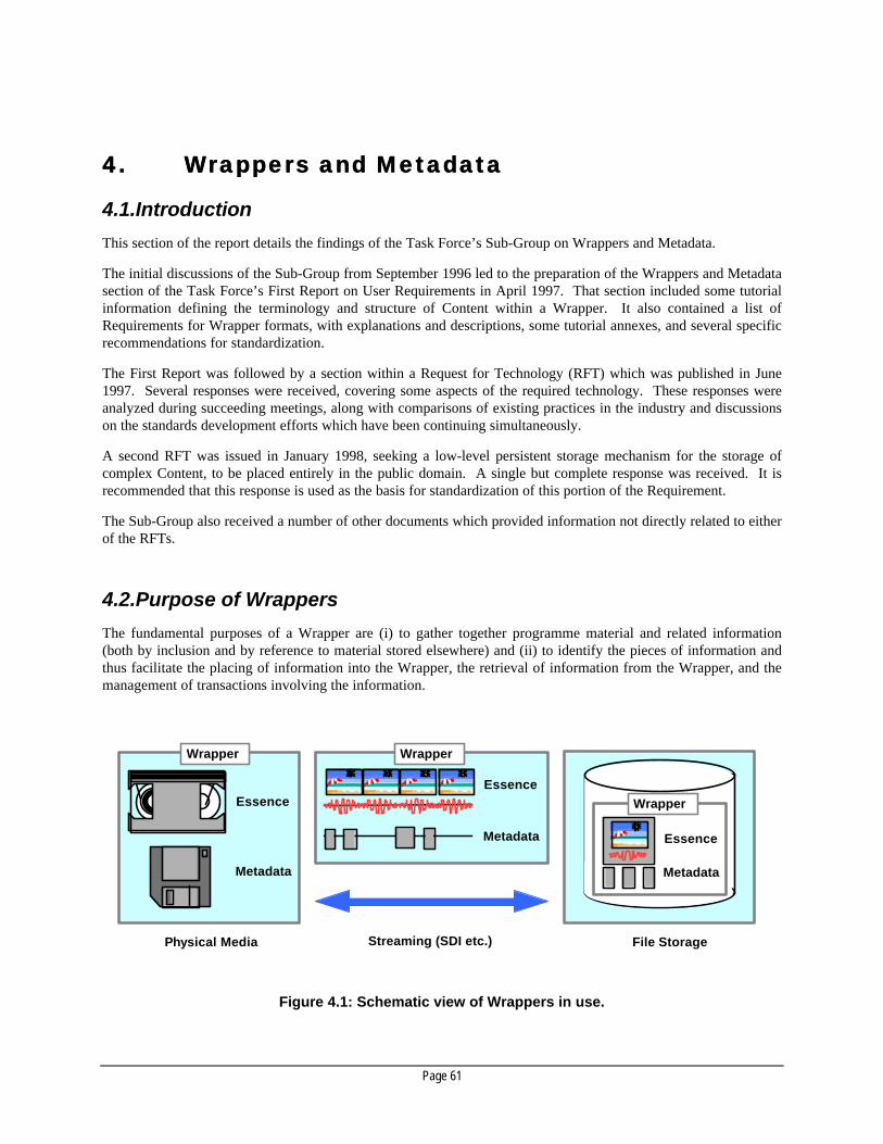
Page 61
4.4. Wrappers and MetadataWrappers and Metadata
4.1.Introduction
This section of the report details the findings of the Task Force’s Sub-Group on Wrappers and Metadata.
The initial discussions of the Sub-Group from September 1996 led to the preparation of the Wrappers and Metadatasection of the Task Force’s First Report on User Requirements in April 1997. That section included some tutorialinformation defining the terminology and structure of Content within a Wrapper. It also contained a list ofRequirements for Wrapper formats, with explanations and descriptions, some tutorial annexes, and several specificrecommendations for standardization.
The First Report was followed by a section within a Request for Technology (RFT) which was published in June1997. Several responses were received, covering some aspects of the required technology. These responses wereanalyzed during succeeding meetings, along with comparisons of existing practices in the industry and discussionson the standards development efforts which have been continuing simultaneously.
A second RFT was issued in January 1998, seeking a low-level persistent storage mechanism for the storage ofcomplex Content, to be placed entirely in the public domain. A single but complete response was received. It isrecommended that this response is used as the basis for standardization of this portion of the Requirement.
The Sub-Group also received a number of other documents which provided information not directly related to eitherof the RFTs.
4.2.Purpose of Wrappers
The fundamental purposes of a Wrapper are (i) to gather together programme material and related information(both by inclusion and by reference to material stored elsewhere) and (ii) to identify the pieces of information andthus facilitate the placing of information into the Wrapper, the retrieval of information from the Wrapper, and themanagement of transactions involving the information.
Wrapper
Essence Essence
Essence
Metadata
Metadata
Metadata
Physical Media Streaming (SDI etc.) File Storage
Wrapper
Wrapper
Figure 4.1: Schematic view of Wrappers in use.

Page 62
4.3.Overall concepts - terminology and structure
4.3.1. General
Wrappers are intended for use in linking physical media together, for streaming of programme material acrossinterconnects, and to store programme material in file systems and on servers. This and other terminology isdiscussed in this section.
The Sub-Group adopted terminology and structure very close to that defined by the Digital Audio-Video Council(DAVIC) in its Specification V1.2 – the section on Content Packaging and Metadata (baseline document 22) – asfollows:
• programme material and related information of any variety is called Content;
• the parts of Content which directly represent programme material (such as signal samples) are called Essence;
• the parts which describe the Essence and other aspects of the material are called Metadata;
• Content is composed of Content Packages, which in turn are composed of Content Items, which are furthercomposed of Content Elements;
• Content is contained in Wrappers which must be capable of including Essence, Metadata and other Overheadin differing proportions and amounts, depending upon the exact usage of each Wrapper.
4.3.2. Storage, Streaming, File Transfer and editing of Content
When Content is gathered and placed onto tape or disk for later access, it is kept in a Storage Wrapper. The basicform of these Storage Wrappers can be very simple and generic as will be described later in this document.
Applications for Wrappers will include those where Content is primarily to be transferred between origination,display, transmission and storage devices, using signal interconnects such as SDTI or network interconnects suchas Ethernet or Fibre Channel. These are referred to as Streaming applications, and the Wrappers used are referredto as Streaming Wrappers.
These differ from Storage Wrappers in two respects:
• some Overhead may be added to the stream to assist or guide the interconnect layer;
• the specific interleaving and multiplexing structure that are used may be optimized for the interconnect.
Applications will also include those where Content is intended to be randomly accessed, searched, modified andbrowsed – referred to as Editing applications. In these latter applications, the collections of Content are calledContent Packages. They will often remain simple, but may also become very complex and contain many inter-relationships.
Editing applications may need to exchange either Content Items or Content Packages with each other; they will alsoneed to exchange Content Items with Streaming applications. For exchanges between Editing applications andStreaming applications (e.g. playout), Streaming Wrappers will be used. For exchanges using File Transfermethods, Storage Wrappers can be used. For exchange between Editing applications resident on the samecomputer, or sharing the same local or network file system, it is not necessary to use any Wrapper.
While Content is in use by Editing applications, Content Packages will be subject to frequent change – as a result ofadding and removing Content Items and Content Elements, and by modification of the Essence and Metadatathroughout the Content Package.
When there are constraints on the variety of Content within a Content Package, and there is foreknowledge of theextent of likely modification to the Package, provision can be made within a generic Wrapper to accommodate anygrowth of the Content as it passes from application to application.

Page 63
In other cases, to promote efficiency, it may be necessary to store the Content Package in a format which providesfor flexible growth and rearrangement of the data. This special-purpose storage format may also provide advancedfunctions for the management of the Content Package.
Some possible application combinations and Wrapper choices are summarized in the following table:
Source:→→Destination:↓↓
Streaming application Editing application
Streaming application Streaming Wrapper Streaming Wrapper
Remote Editing application via Streaming Streaming Wrapper Streaming Wrapper
Remote Editing application via File Transfer N/A Storage Wrapper
Local Editing application N/A Custom or Storage Wrapper Note: For most interchange scenarios, a Streaming Wrapper is employed.
4.3.3. Content structure
A Wrapper does more than just contain Content; it also defines and describes the structure of the Content. Themicroscopic structure of Content is inherent in the Essence itself; the macroscopic structure is built using Metadataand Overhead (see below), and is classified as described here.
Each individual item, either Essence or Metadata, is called a Content Component – for example, a block of audiosamples, or a timecode word. A Wrapper contains some number of Content Components, built into a logicalstructure.
A Content Element (CE) consists only of Essence of a single type, plus any Metadata directly related only to thatEssence – for example, the blocks of samples of a video signal plus the Essential Metadata which describes thesample structure plus the Descriptive Metadata which identifies the origin of the signal.
This can be expressed by the simple equation: Content equals Metadata plus Essence.
An exception to this definition is when a Content Element can be generated entirely from Metadata, without theneed for Essence – for example, an encoded subtitle. In these cases, the Metadata either refers to external rawEssence or to a device or algorithm which creates Essence.
Types of Essence include Video, Audio and Data of various kinds, including captions, graphics, still images, text,enhancements and other data as needed by each application.
• A Content Item (CI) consists of a collection of one or more Content Elements, plus any Metadata directlyrelated to the Content Item itself or required to associate together the component parts (Content Elements) – forexample, a Video clip.
• A Content Package (CP) consists of a collection of one or more Content Items or Content Elements, plus anyMetadata directly related to the Content Package itself, or required to associate together the component parts(Content Items and Content Elements) – for example, a programme composed of Video plus Audio plussubtitles plus description.
An example of a such a collection of Content Items and Content Packages contained in a Wrapper is shown inFig. 4.2.

Page 64
Although these terms describe larger and larger structures of Content, the smaller structures do not have to be fullycontained within bigger ones. For example, a single Wrapper could contain Content Elements equal to a full hourof programme source material, and Content Packages describing only a couple of five-minute segments within thematerial.
Thus, a Wrapper is not restricted to contain any specific quantity or portion of any of these constructs – it maycontain only a few Content Components, or as much as several Content Packages. When a Wrapper contains oneor more Content Packages in combination with other Content Items, it becomes a Complex Content Package asillustrated in Fig. 4.3.
Besides using a single Wrapper, two or more Wrappers may be used to transport components of a single ContentItem or Content Package where separate transport mechanisms are used. In this case, each of the Wrappers willcontain a partial common set of Metadata to allow the Wrappers to be cross referenced. This is the mechanismused where not all of the Metadata can be accommodated in the transport used for the Essence.
Wrapper
These are all Content Components:
Essence Component (Video)
Essence Component (Audio)
Metadata Item
Association Metadata (eg Timecode) Essence Component (Other Data)
Vital Metadata (eg Essence Type)
Content Package
Content Item Content Item
Content Element Content Element
Content Element Content Element
Content Item
Content Element
Content Element
Content Element
Content Package
Content Element
Content Element
Figure 4.2: Content Package: Packages, Items, Elements and Components.

Page 65
Content Package
(Simple Content)
Content Item (Index)
Content Item
Wrapper
Content Item
Content Element
Content Item (Composition Metadata) Content Element
Content Item
Content Package
(Complex Content)
External Reference
Content Element
Content Element
Content Element
Content Element Content Element
Content Element
Figure 4.3: Complex Content Package: Packages, Items, Elements, Components and Metadata.
4.3.4. Essence
Raw programme material itself is referred to as Essence. Essence is the data that represents pictures, sound andtext; types of Essence include Video, Audio and Data of various kinds, including captions, graphics, still images,text, enhancements and other data as needed by each application.
Some varieties of Essence may be treated as Metadata in certain circumstances. For example, a sequence ofcaptions should be regarded as a kind of Data Essence when it is inserted into a broadcast television signal but,within an Asset Management system, the same captions may be used to index and describe the Content, and shouldbe regarded as Descriptive Metadata. This dual perspective is also presented from the point of view of Metadata inthe next section.
The task of interpreting Essence as Metadata may be carried out in an extraction step which results in duplicationof the information, or it may be a dynamic process in which the same information is used in either sense upondemand. Additionally, the specifications of some Essence formats include embedded items of Metadata which willneed to be extracted and promoted into separate Metadata items for efficient systems operation.
Essence may be encoded or compressed in whatever way is appropriate. It is typically structured in packets, blocks,frames or other groups, which are collectively called Essence Components. The microscopic structure of Essence

Page 66
Components depends on the particular encoding scheme used, which in turn is identified by Essential Metadata (seebelow).
Essence typically has the characteristic of a stream; it provides sequential access whether stored on a file device or astreaming device. Stream data will normally be presented in a sequential time-dependent manner. Essence storedon a file storage device can be randomly accessible. Essence not having the characteristic of a stream (e.g.graphics, captions, text) may still be presented in a sequential time-dependent manner.
4.3.5. Metadata
Other information in the Content is referred to as Metadata. Metadata is broadly defined as “data about data”.
The number of distinct varieties of Metadata is potentially limitless. To assist with describing its requirements andbehavior, Metadata is divided into several categories, depending upon its purpose, including at least the following:
• Essential – any information necessary to decode the Essence. Examples: Unique Material Identifiers (UMIDs),video formats, audio formats, numbers of audio channels.
• Access – information used to provide and control access to the Essence. Examples: copyright information,access rights information.
• Parametric – information which defines detailed parameters of the Essence. Examples: camera set-up,pan & scan, colorimetry type.
• Composition – required information on how to combine a number of other components (e.g. video clips) into asequence or structure (Content Element, Content Item or Content Package). This may equally be regarded asinformation recording the heritage or derivation of the Content. Examples: Edit Decision Lists (EDLs), titlinginformation, zoom lens positioning (for virtual studio use), transfer lists, color correction parameters.
• Relational – any information necessary to achieve synchronization between different Content Components,and to achieve appropriate interleaving of the components. Examples: timecode, MPEG SI.
• Geospatial – information related to the position of the source.
• Descriptive – all information used in the cataloguing, search, retrieval and administration of Content.Examples: labels, author, location, origination date & time, version information, transaction records, etc.
• Other – anything not included above. Examples: scripts, definitions of the names and formats of otherMetadata, user-defined Metadata.
Within each category, Metadata may be further divided into sub-categories.
As noted in the previous section, some varieties of Metadata may be treated as Essence in certain circumstances.For example, within an Asset Management system, a sequence of key phrases may be used to index and describe theContent, and should be regarded as Descriptive Metadata; but if the same text is converted into captions andinserted into a broadcast television signal, it should be regarded as a kind of Data Essence. The task of interpretingthe Captions as Data Essence may be carried out in a rendering step, resulting in duplication of the information, orit may be a dynamic process in which the same information is used in either sense, upon demand.
4.3.6. Metadata characteristics
Metadata which is absolutely necessary for the operation of systems is referred to as Vital Metadata. The systemmust provide values for this kind of Metadata. The specific set of Vital Metadata may be different for eachapplication; but it always includes at least the Essential Metadata. Any item of Metadata may be Vital, independentof its position within the Metadata class hierarchy.
It was realized that the core set of Vital Metadata is relatively small, consisting of the Essential Metadata (UMIDand the basic Essence type), and some Relational Metadata. Specific applications may require additional items ofVital Metadata (for example, commercial playout applications require the use of an identifier or ISCI number).

Page 67
Metadata which is related to the whole of a subsection of the Content (for example a Content Item or ContentPackage) is referred to as Static Metadata.
Metadata which is related to a subsection of the Content (e.g. a single Content Component, a Content Element, or aframe or scene) is referred to as Variant Metadata. The variation will frequently be connected to the timing of theContent, but may also be associated with other indexing of the Content. Most categories of Metadata may beVariant.
Further such characteristics of Metadata items have already been identified, while others may well be identified inthe future.
During a Streaming transfer, there will be certain types of Metadata that require periodic repetition. This willallow the user to enter the stream asynchronously and, within a given time period, recover the Metadata asdetermined by the repetition rate. This is called Repeated Metadata. It is discussed further below in Section4.7.6.
It might normally be assumed that all Essence and Metadata should be preserved as far as possible throughout thebroadcast chain. However, some Metadata types may intentionally be destroyed after they have served their usefulpurpose. Examples of Transient Metadata (with “short” permanence) include Machine Control, QoS Control,Error Management and Encoder Control. Examples of Permanent Metadata include Essential Metadata such asUnique Material Identifiers, and timecode.
Metadata may be kept with the associated Essence or kept elsewhere. Factors contributing to the choice includeallocation of available bandwidth, ease of access, and concern for systems reliability and error recovery. Tightly-Coupled Metadata (above some priority threshold) will be stored and transmitted with the primary Essencewithout compromise, and will possibly be duplicated elsewhere, while Loosely-Coupled Metadata (below thepriority threshold) may be stored and transmitted separately.
These characteristics of Metadata must be recorded in the relevant Standards documents and in the SMPTERegistry as part of the definition of the Metadata items (see Section 4.5.3.).
4.3.7. Overhead
In addition, the construction of the Wrappers themselves will require some additional items of data. This data isreferred to as Overhead. Overhead includes such things as flags, headers, separators, byte counts, checksums andso on.
The composition of Wrappers can be expressed by the following simple relationships:
• an empty Wrapper is made up of Overhead only;
• a full Wrapper is made up of Content plus Overhead;
• Content equals Metadata plus Essence;
• Hence, a full Wrapper is made up of Overhead plus Metadata plus Essence.
4.3.8. Metadata Sets
Metadata may be grouped into sets which are referenced as a single item. Such groupings are known as MetadataSets. Such sets can be referenced by a single key value rather than by identification through each individualMetadata item; individual items within the sets may be identified with sub-keys, or perhaps implicitly within fixedformatting of the set.
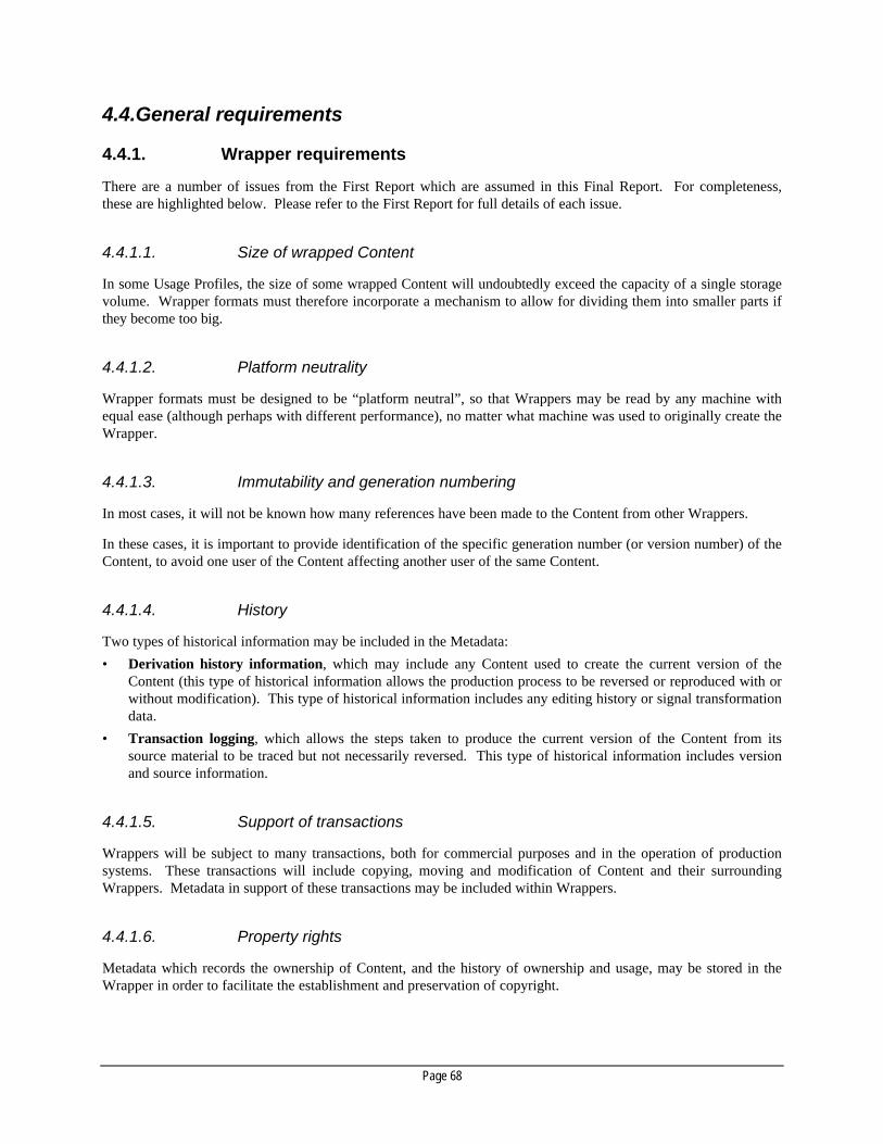
Page 68
4.4.General requirements
4.4.1. Wrapper requirements
There are a number of issues from the First Report which are assumed in this Final Report. For completeness,these are highlighted below. Please refer to the First Report for full details of each issue.
4.4.1.1. Size of wrapped Content
In some Usage Profiles, the size of some wrapped Content will undoubtedly exceed the capacity of a single storagevolume. Wrapper formats must therefore incorporate a mechanism to allow for dividing them into smaller parts ifthey become too big.
4.4.1.2. Platform neutrality
Wrapper formats must be designed to be “platform neutral”, so that Wrappers may be read by any machine withequal ease (although perhaps with different performance), no matter what machine was used to originally create theWrapper.
4.4.1.3. Immutability and generation numbering
In most cases, it will not be known how many references have been made to the Content from other Wrappers.
In these cases, it is important to provide identification of the specific generation number (or version number) of theContent, to avoid one user of the Content affecting another user of the same Content.
4.4.1.4. History
Two types of historical information may be included in the Metadata:
• Derivation history information, which may include any Content used to create the current version of theContent (this type of historical information allows the production process to be reversed or reproduced with orwithout modification). This type of historical information includes any editing history or signal transformationdata.
• Transaction logging, which allows the steps taken to produce the current version of the Content from itssource material to be traced but not necessarily reversed. This type of historical information includes versionand source information.
4.4.1.5. Support of transactions
Wrappers will be subject to many transactions, both for commercial purposes and in the operation of productionsystems. These transactions will include copying, moving and modification of Content and their surroundingWrappers. Metadata in support of these transactions may be included within Wrappers.
4.4.1.6. Property rights
Metadata which records the ownership of Content, and the history of ownership and usage, may be stored in theWrapper in order to facilitate the establishment and preservation of copyright.

Page 69
As a minimum requirement, it must be possible to tell from the Property Rights Metadata the identity of theContent which is contained in the Wrapper. In cases where more than one item of Content is included, multipleinstances of the Property Rights Metadata must be permitted.
However, there are many additional requirements for a fully-functioning Property Rights protection system, whichare described in “Annex D, Section D3 – Access Control and Copyright” of the First Report. Although not all thesefunctions and capabilities are required in all studio systems, the increasing use of permanently-connected networksimplies that protection of Property Rights should be considered in the design of every system.
4.4.1.7. Compatibility and conversion
Wrapper formats must be Compatible with existing formats, including formats for Essence (however stored ortransported) and formats for Metadata. In addition, the use of Wrappers must be compatible with establishedworking practices.
It is recognized, however, that when existing Essence and Metadata formats are included within programmematerial, some of the benefits to be obtained from new Wrapper formats may not be available.
• A format is Compatible with a Wrapper format when Metadata or Essence can be directly placed in a Wrapperfrom the source format or directly exported from a Wrapper.
• Lossless Conversion is possible when Metadata or Essence cannot be used directly but can be translated into orout of the Wrapper with some processing, and the conversion can be fully reversed.
• Lossy Conversion is possible when Metadata or Essence cannot be used directly but can be translated into orout of the Wrapper with some processing and some loss of meaning or quality, and the conversion cannot befully reversed.
Users will require Lossless Conversion or better in all cases, except where Content from outside a Wrapper isinvolved; in this case, users will require Lossy Conversion or better.
4.4.1.8. Extensibility
Any new Wrapper format to be developed is required to be standardized and to have reasonable longevity ofdecades or more. It is certain that new Metadata types and Essence formats will be required within the life of anystandards document. Therefore, every Wrapper format is required to be extensible in the following ways:
• by the addition of new Essence and Metadata types;
• by the extension or alteration of data syntax and semantics.
To achieve maximum backwards compatibility, the addition of new Essence and Metadata types must be achievedwithout change to the underlying Wrapper data syntax; efficient and complete documentation must be provided toensure that any extensions are equally accessible to all implementations. This will depend upon maintenance of aproper Registry of Data Identifiers.
When unknown identifiers are encountered in the processing of a Wrapper, they (and any attendant data) should beignored gracefully.
4.4.1.9. Other requirements
Wrappers must be capable of including Essence, Metadata and Overhead in differing proportions and amounts,depending upon the exact Usage Profile of each Wrapper.
For example, a programme replayed from videotape might include video, audio and ancillary data streams, withalmost no Metadata; an Edit Decision List might include Descriptive and Composition Metadata, but little or no

Page 70
Essence. Each particular variety of Wrapper will contain a minimum defined level of Essence, Metadata andOverhead.
Wrappers must be capable of including various structures which are combinations of Essence and Metadata, such asthe Content Elements, Content Items or Content Packages defined above.
Metadata may be contained in a video or audio data stream (e.g. MPEG or AES-3 streams) but, for ease of access, itcould be replicated in a separate Metadata area. Real-time live transfer by streams may require the repeating ofMetadata and the interleaving of structures.
As well as directly including Essence and Metadata, Wrappers may contain indirect references to either. This willbe discussed later in this document.
4.4.2. APIs
The complexity of management of the Content in the face of all these requirements creates the requirement for anApplication Programming Interface (API) to be generally available, at least for the management of ComplexContent Packages and probably even for manipulation of Streaming Wrappers. The API should provide functionsfor locating elements within the file, for reading and writing Essence, Metadata and complete Content elements,and for maintaining the integrity of the data structures and indexes within the file.
While the work of the Sub-Group has been focused at the file level, it has also discussed the need for prototype orreference APIs to speed the adoption of the file format. These APIs should be the basis of future standardization bythe SMPTE or other standards bodies.
It is most important for standards bodies to document the formats themselves in the first instance; APIs areinherently more difficult to standardize and such work should be tackled at the same time as implementation of thestandard formats.
General guidelines for the reference API are as follows:
• Hierarchical API – it is envisioned that the API and its standardization will occur at multiple levels. At thelowest level, the API will handle core data management. The next level will include facilities that enableaccess to named objects / parameter-value pairs. Finally, application-level interfaces will provide higher-levelfunctions such as traversing a timeline.
• Multi-platform support – while not mandatory, it is desirable to have implementations of the API that operateon more than one platform.
• Full support of the file format – the API should provide facilities for complete access to all the data includedin the file format.
• API documentation – for the API to be useful and be considered for future standardization work, complete andclear documentation is required. Such documentation should be sufficiently complete for anyone to re-implement the API from scratch.
• Sample code – a sample application using the provided API will help greatly in showing accepted practice forthe use of the API. The sample application does not need to be complex but should implement basic operationson the file format.
4.4.3. Breadth of application and Wrapper profiles
Users would strongly prefer one solution to cover the widest range of applications.
Because of the limitations of technology and the concerns listed below, it is unlikely that a single Wrapper formatwill fit all applications. However, if multiple formats are to be developed, they must be created with a view to

Page 71
maximum commonality, understanding that programme material may appear in, and be converted between, any orall of the formats during its lifetime.
The range of production processes can be encapsulated into Wrapper Profiles, each calling for one or more of thepossible Wrapper formats.
During the study, a wide range of potential activities were listed, which were then grouped into the followingcategories:
• Pre-production;
• Production and Acquisition;
• Post-production;
• Distribution and Storage;
• Emission and Transmission;
• Archiving.
Every application involves one or more of these processes, and each process makes use of Content in each of severalforms:
• Unwrapped (for example, a videotape);
• Streaming Wrapper (for example, on an SDTI channel or as an MPEG stream);
• Storage Wrapper (for file transfer);
• Special Purpose (for example, a database together with signal storage).
These forms reflect the retrieval and editing functionality which is required within each process stage.Furthermore, as well as being used within each process, these forms are all used as interfaces between processes.
There is therefore a requirement for several Wrapper format types (Storage, Streaming and Special Purpose) inaddition to the continued use of unwrapped Content.
4.4.4. Framework of a solution
During the Sub-Group’s studies, the Recommendations from the First Report were reviewed and extended, and arenow as follows:
• The development of an extensible hierarchical classification of Metadata varieties, including the notion ofMetadata Sets (templates) appropriate to particular uses.
• The establishment of a single registry of Metadata item names and definitions, including a registry of EssenceFormats. Essence Formats are specific values of a particular Metadata item.
• The development of an initial core set of Essence Format specifications.
• The standardization of a single format for a “Unique Material IDentifier (UMID)”. It is recognized howeverthat multiple formats are already in use and will continue to be introduced. As a minimum therefore, it shouldbe possible to register existing and new unique identifier formats within the Metadata registry referred toabove. We recommend the creation of a new standard to be a target for the industry to converge upon.
• The standardization of a single generic Wrapper for the Streaming of Metadata, which can be mapped ontoexisting and emerging signal transport layers, and which can be used to stream Content (Metadata multiplexedwith Essence) onto the transport layer. It is understood that there will be many specific solutions for streamingfile formats, each one optimized for a given transport layer and application; interoperability can be promotedby allowing the same Metadata to be accessed with equal ease and without translation from each stream.
• The standardization of a single generic Wrapper for the Storage of Content.
• The standardization of a single generic format for representation of Complex Content Packages, forapplications requiring arbitrary complexity of Content of all types, including Metadata and Essence. This

Page 72
format must be highly compatible with the Metadata streaming format described above, allowing the sameitems of Metadata to be accessed when the Content Package is within a stream or within an application.However, it should be noted that Complex Content Packages are usually not expected to be interpreted whilethey are being moved by a streaming application.
4.5.Metadata requirements
4.5.1. Metadata vision
Many standards development efforts are underway in this area, both within the SMPTE and in other closely-relatedareas in television and in information systems in general. Metadata is one of the most important emergingtechnologies of the digital motion imagery (video and audio) age. It is a key enabling technology that will changethe very nature of how motion imagery is created, viewed and used.
At its simplest level, Metadata is “data about the data.” It is the data about the motion imagery but it is not theimagery bits themselves. As described above, the imagery bits themselves are called “Essence”.
4.5.2. Requirements for Metadata standards
Metadata standards will be based on the following general approach:
• Specification of a general scheme for the hierarchical naming of items of Metadata, based upon an SMPTEUniversal Label (SMPTE 298M). This is explained further in the “Registry” section below.
• Harmonization of diverse Metadata Sets, by defining a common lexicon or dictionary (which defines the placeof groups of Metadata items within a hierarchy). This dictionary of defined Metadata items, plus theirmeaning, purpose and allowed formatting, will be created by reconciling the existing work of bodies such asthe “Dublin Core” group, The Library of Congress and others, and by adding Programme-Material-specificitems which are known requirements today. Many of the requirements and Metadata types identified in theFirst Report included: Essential Metadata such as format, basic signal parameters and Unique MaterialIdentifiers; Association Metadata for the synchronizing, referencing and indexing of Content items;Composition or Usage Metadata; Asset Management Metadata, including material generation numbering, andderivation and processing history; Descriptive Metadata including a general description of access and propertyrights; Access Control Metadata and transactions on Content; and many other types.
• Studies indicate that almost every Metadata type can be grouped easily into one of the following majorcategories or Metadata Classes previously described:
Class 0: (SMPTE-defined) Transport Stream (or File) Header
Class 1: Essential Metadata
Class 2: Access Metadata
Class 3: Parametric Metadata
Class 4: Composition Metadata
Sub-class 4.x Heritage Metadata
Class 5: Relational Metadata
Sub-class 5.x Temporal Metadata
Class 6: Geospatial Metadata
Class 7: Descriptive Metadata
Class 8: Other Registered Metadata
Sub-class 8.x External Reference Metadata
Class 9: User-defined Metadata

Page 73
• Procedures must be formalized for adding new items into the Metadata dictionary, corresponding to the ClassRules described below.
• As new items of Metadata are added, particular attention must be paid as to whether they are essential (Class1), or whether they should be added into the other classes (2~9).
• A new type of standards document will be taken up by the SMPTE and perhaps similar bodies, called aDynamic Document. A Dynamic Document is like a regular standards document except that it is used incombination with a public registry of extensions to the standard. The registry is still updated and expanded bydue process, but the review and updating cycle can take place much faster than before. This leads to standardswhich remain more current.
4.5.2.1. Class rules
4.5.2.1.1. Classes 0-7: publicly-defined and due-process Standardized (a.k.a. Registered)
Consists of due-process standardized specifications. It is generally expected that these types will be known to allsystems. In cases where a data type is inappropriate for a particular application, systems should be able to safelyidentify data types and pass them through the system. It is also expected that any application claiming use of thisRegistry be up-to-date with all registered data types at the time of release. Ideally, systems should have the abilityto import information on new registered data types for the purpose of identification. Registered data types would bereviewed and accepted by the SMPTE and are general-purpose enough that it is not unreasonable for an applicationto support them all.
4.5.2.1.2. Class 8: registered as private with public description
Class 8 data consists of types that have been well defined but whose detailed description is not publicly available(but can be obtained through proper licensing), or that have been publicly defined but have not yet been accepted asClasses 0-7 types. It is likely that most data types will start as Class 8 and progress to Classes 0-7 over time as theyare accepted. Applications may decide to support any number of Class 8 data types. While it is possible forapplications to claim full support for all Classes 0-7 data, it is unlikely that any one application will posses theability to, or have the need to, support all Class 8 data types.
4.5.2.1.3. Class 9: unpublished with no public description (user-defined, proprietary orexperimental)
Class 9 data consists of types that are in general private data with a registered identifier. Full specifications are notavailable. All applications should be able to ignore Class 9 data. Class 9 types may not be exported forinterchange.
4.5.3. Registry
The Registry is a central premise of the new paradigm of Wrappers, the Metadata dictionary, and SMPTE“Dynamic Documents”. To achieve their full potential, these all require a public repository of registered uniquelabels and associated descriptions, maintained by due process, with international visibility.
The concept of unique labels was developed by the SMPTE in the years up to 1996, resulting in SMPTE 298M-1997 “Universal Labels for Identification of Digital Data”. SMPTE Universal Labels will be applied liberally toWrappers and Metadata, for all of the following purposes:
• as the names of Metadata items;
• as the names of Metadata Sets and templates;
• as the preamble for Unique Material Identifiers (UMIDs);

Page 74
• as a management tool for “dynamic documents”,
• to be assigned as “magic numbers” as required to uniquely identify digital bitstreams, formats and files, inorder to promote global interoperability in the digital domain.
The Sub-Group recommends that the SMPTE Registration Authority, Inc. (SRA) be designated as the centralRegistration Authority for the motion imagery and audio technology domains. The SRA will be operational inearly 1998. The Sub-Group notes that the SRA has been designated by the ISO to be the Registration Authority forMPEG-2 “format-identifiers” or RIDs, and has been designated by the ATSC as the Registration Authority forATSC programme identifiers.
4.5.3.1. Registration Authority activities
The SMPTE Registration Authority will carry out the following activities:
• Manage the Universal Label System.
• Use the Universal Label System to define the “keys” of the Metadata dictionary. The dictionary will includedomain-specific vocabularies, detailing the sets of Metadata items appropriate for specific applications.
• Specify and publish an initial baseline universal dictionary of Metadata for use in many applications.
• Establish a due-process procedure for extending the dictionary in discrete revisions (versions 1.0, 1.1, 1.2, etc.)as the basis for compliance, where new versions must be backwards compatible with previous versions. Dueprocess will be conducted by a designated SMPTE Engineering Committee which will delegate daily operationsback to SRA staff.
• Establish liaisons with other due-process bodies, as appropriate, to enable interoperable Metadata.
• Establish a Registry which is capable of containing both standardized specifications and also user definitionsfor installation- or system-specific Metadata items, to serve the requirement for extensibility.
4.5.4. Metadata Templates
The Metadata subset required by and supported by all applications is also known as the Essential Metadata.
Beyond the Essential Metadata Set, Templates will establish conventions for the Vital Metadata Set (i.e. therepertoire, level and complexity of Metadata) necessary for each category of application. A key set of Templateswill be defined by due-process standards.
A default behavior must be defined within each Metadata Set for Templates that do not support that set.
4.5.4.1. Production planning
In this Template, pure Metadata is created, e.g. storyboards, scripts, crew schedules.
4.5.4.2. Acquisition and playback
The acquisition and playback systems only need Essential Metadata support in order to identify and document theContent represented by the Essence. However the system should allow full extensibility. This Template makes useof both Streaming and Storage Wrappers.
4.5.4.3. Editing and mixing
Editing and mixing applications demand a very high level of functionality and complexity in the area of Metadata.The storage format likewise, requires a sophisticated system which allows in-place editing of Metadata along with

Page 75
full random access. Due to the nature of these systems, a hierarchical storage mechanism may be a requirement formanagement of such a large amount of Metadata and associated relationships.
4.5.4.4. Storage of consolidated programs
The result of the production process is a consolidated programme. In consolidation, it is usually acceptable toreduce the Metadata to the minimum required for such use. The requirements for in-place editing can also berelaxed, allowing simpler storage formats to be used for the Metadata. Depending on the target distribution format(see next section), both the Essence and Metadata may need to be converted to formats more suitable for suchtransmission. It should be noted that, while such conversion usually results in a reduction of Metadata, it may benecessary to add additional Metadata which describes specific distribution and transfer attributes (such as licenserights).
4.5.4.5. Emission
Efficient storage and transmission of Content often requires Wrapper formats that are optimized for minimallatency and efficient access. This would generally mean that the amount of Metadata can be reduced to theminimum necessary. Furthermore, the transmission channel may impose additional requirements on the maximumquantity of Metadata that can be handled. On the other hand, additional Metadata may be required to handletransmission-specific requirements.
It is explicitly recognized that different transmission domains (e.g. SDTI versus IP) require a different set ofMetadata to accompany the Content, due to the varying needs of each environment. For example, in an IP system,one may want to add additional Metadata in the form of a URL which points to related text and graphics for theContent. Such Metadata, however, would not probably be necessary when Content is being transmitted in a studioenvironment over SDTI.
4.5.4.6. Archiving
Ideally, an archive system needs a superset of the acquisition Template plus production history. SufficientMetadata needs to exist to allow fast and efficient identification of the Content. Additional Metadata may beincluded to describe detailed characteristics of the Content to allow precise searching of the Content. Extensibilityis once again a high requirement in order to allow inclusion of customer-specific data such as links to computerdatabases or billing systems. Applications may use hierarchical storage to contain such Metadata.
4.6.Unique Material Identifiers
To enable the tracing of Content as it passes through a system, it is extremely important to provide a uniqueidentifier of the actual Content contained in the Wrappers. Such a Unique Material Identifier (UMID) is necessary,since multiple identical or near-identical copies of the Content may exist within the system in various locations, andthey must be referred to, independent of their location. It is also necessary to refer to Content which has beentemporarily removed from the system, for example when transferred to archival storage, or when delivered out ofthe system, or even before the Content has been created.
Unique Material Identifiers are also used to trace copyright information and ownership of finished programs. Inthe publishing industry, these identifiers are called ISBN numbers and such like; a well- known example in use intelevision today is the ISCI number used for identifying commercials. Work is also under way to define anInternational Standard Audio-visual Number or ISAN. The Advanced Television Systems Committee (ATSC) hasalso specified a Programme Identifier within the US Digital Television bitstream. Besides these UniqueProgramme Identifiers (UPIDs), in television production there is also a need to uniquely identify unfinishedmaterial, including both source material and transient or intermediate Content Elements.

Page 76
File formats and Asset Management systems must be able to continue to work with existing methods of materialidentification but, at the same time, it would be beneficial to define a standard scheme for constructing UMIDs toenable greater interoperability of new systems as well as to provide the potential to upgrade existing systems.
4.6.1. Standard UMID Core
A standard UMID must be constructed from several parts:
1a. Prefix; 1b. Unique Material Number; 1c. Unique Instance Number; 2. Core Data; 3. Status Metadata; . . . plus (optionally), Extension Metadata.
The Prefix is an SMPTE-administered Universal Label which identifies that this is an SMPTE UMID. It mayadditionally include other registered information such as the identification of the country and facility.
The second part of the UMID is a globally-unique material number whose method of generation is yet to be defined.
The third part is a locally-unique “instance” number whose purpose is to indicate the current version of thematerial. The source material would have a null value while other instances of the same material (copies etc.)would be assigned non-zero numbers through an algorithm (yet to be defined) which is intended to ensureuniqueness of every instance.
These first three parts of a standard UMID could be contained within a short field, perhaps as small as a 16-bytebinary number, but certainly no larger than 24 bytes.
All fields in the UMID could potentially be automatically generated for every Content Element. Where automaticgeneration is not possible, the data could be assigned from a database following rules that guarantee to ensureuniqueness. For automatic generation, various algorithms are possible, employing techniques such as time countersand random number generators. Exact algorithms are expected to be defined during the standardization process.
The second major part is the Core data. The Prefix data, in conjunction with the Core data, forms the UMID Coreitself. Allocation for the UMID Core should be assigned as early as possible in the production chain, preferably atthe source. Once a value has been assigned to any UMID Core component, it cannot be changed and must alwaysremain attached to the associated Content Element.
The third (Status) part of a UMID consists of modifiers and status indicators to identify near-identical copies,versions, generations and representations of the Content Element – the length, format and use of this third partshould be specified by each particular system. This might also include element identifiers to allow a single UMIDCore to be applied to an entire Content Item, not just a Content Element.
In some cases, encoding the Status Metadata as a single qualifier field can simplify or speed up operation of asystem. In other cases, it may be more appropriate to keep the information as defined items of Metadata, withindividual names and specifications.
All UMID Core data can be automatically generated using, for example, Geospatial Metadata such as the positionof the source and the data, and the time of Essence capture.
The Status Metadata allows the Content to be labeled with the current status of the current instance, as it progressesthrough the production chain. This Status Metadata is editable when the Content is cloned, copied or in any waychanged from the source. Ultimately, if the Status Metadata database file were lost, the UMID Core could stillprovide enough information to assist in manually identifying the Content source.

Page 77
Note that the UMID Core applies to the whole Content Element as static data. Within a Content Element,additional resolution is provided by supplying the datecode and timecode numbers, or other Temporal Metadata.
The Essential Metadata Set which is needed to access each Content Component is thus comprised of the UMIDCore plus some portion of the Status Metadata, dependent upon the precise application.
Some applications may also allow the addition of optional Extension Metadata. This is categorized as Metadatawhich is useful to distinguish a particular aspect of the current representation of the Content but which, if lost,would still allow the Content to be used in a useful way. Extension Metadata is freely editable and often manually,rather than automatically, entered.
The exact formatting and total data requirement for the UMID Core plus Status Metadata will be determined duringstandardization. Examination of “strawman” proposals indicates that the total size will not exceed 64 bytes perframe.
4.6.2. UMIDs as a linkage between Streams and Databases
Fig. 4.4 gives a general view of the linkage between the UMID Core and the Status and Extension Metadata. Thereason for such linkage is that, in most instances, the UMID Core will always be carried with the Content on a per-picture basis, whilst the Status and Extension Metadata will be stored on a server, on a clip basis. Thus, in order toprovide a unique link between the UMID Core and the Status and Extension Metadata, the UMID Core value at theclip start point is included on the server. Therefore, even in the event of a broken link, the UMID Core and itsassociated Status and Extension Metadata file can be re-linked by an automated search process. This may takesome time, but it is at least possible where current systems offer no such possibility.
UM ID UM ID UM ID
UM ID
UM ID
UM ID
UM ID
UM ID
UM ID Core UM ID Core + Status Metadata only UM ID Core + Status & Extended Metadata
Status Data
Status Data
Status Data
Extension Data
Status Data
Extension Data
Status Data
Link Link
Link
Stream Info
Storage Info
Storage Info
Stream Info
OR
Figure 4.4: Illustrated concept of the layered UMID
4.6.3. The UMID Core in Streaming applications
For video signals, a format will be needed to carry the UMID Core data in the VBI as ancillary data. The codingfor the UMID Core data should be able to pass through not just the digital channels but also through compressed

Page 78
VBI channels (as available in MPEG-2 4:2:2P@ML and analog videotape recorders). This is an important aspectof ensuring that the UMID Core can pass through the A/V production chain.
Standards will be required for the formatting of the UMID Core through various parts of the broadcast chain,whether they are carried as Metadata packets alongside of the Essence or embedded within the Essence.
4.7.Wrapper formats
4.7.1. First Request for Technology
Early in the study it was decided to treat the streaming and storage of Wrappers as separate processes and this wasmatched by responses to the First Request for Technology (RFT). Overall, the formats which were targeted directlyat just one or the other (streaming or storage) showed greater flexibility, and a simpler implementation model.Another factor considered in review of the RFT responses was the level of commitment to the standardization ofvarious formats. At this time (July 1998), it is clear that a single format will not satisfy all the requirements.
A number of technologies were separately identified in addition to the RFT responses which are already in theprocess of standardization or available in the public domain.
RFT responses were received for the following storage format technologies:
• Open Media Framework Interchange;
• Structured Storage;
• QuickTime®.
RFT responses were received for the following streaming format and base technologies:
• Advanced Streaming Format;
• QuickTime®;
• SDTI Elementary Streams;
• SX Native and MPEG-2 Transport Streams Multiplexing formats;
• Fibre Channel-AV Simple Container;
• Frame Tables;
• Unique Material Identifier.
Many of these technologies also contain native structures for the formatting of Metadata and other topics outside ofthe direct requirements.
As promised in the RFT process, features from all the RFT responses were combined in this report and, where thisoccurs, the specific sources of each is identified.
4.7.2. Storage Mechanism and Second Request for Technology
From the Wrapper structure diagrams given above, it is clear that a common element of all the RFT responseswhich address Complex Content Packages (“Rich Wrappers”) was the use of a special-purpose persistent storagemechanism at a relatively low level of complexity. In all cases, the data model of the overall system was mappedonto such a storage subsystem.
In addition, most of the Streaming Wrapper responses had an embedded underlying Streaming Mechanism at theNetwork Layer of the OSI model, equivalent to the Storage Mechanism in the storage domain. Just as there areseveral Streaming Mechanisms optimized for particular stream types, we might expect several Storage Mechanismsoptimized for particular storage media and functionality.

Page 79
Hoping to find a broadly applicable solution for a special-purpose Storage Mechanism, the Sub-Group issued aSecond Request for Technology for this specific item. One such proposal was received for a structured storagesystem, and it is recommended that this be forwarded to the SMPTE for standardization.
By adopting an SMPTE Universal Label as an essential requirement in the special-purpose Storage Mechanism,and as a requirement in the actual file, it becomes possible to identify uniquely an SMPTE Storage Wrapper whichis independent of the file name and operating system.
4.7.3. Interoperability of Wrapper formats
Interoperability has several levels:
1. this level ensures the carriage of Essence and Metadata types whatever they may be;
2. this level allows the Essence and Metadata types to be carried and successfully decoded;
3. this level, in addition, allows Complex Content Packages to be interpreted.
Work is already under way to standardize a number of streaming formats through the normal standards processes.In general, this provides level 1 interoperability.
Storage Wrappers have proved to be a more difficult area, but several technologies have been identified which,when applied in simple forms, will help to provide level 2 interoperability.
Achieving level 3 interoperability is still more difficult. However, progress has been made towards this, outside thetraditional television equipment domain, and it is now hoped that engagement of new participants in the standardsprocess, in combination with the general techniques studied by the Sub-Group and discussed here, will result in fulllevel 3 interoperation.
Interoperability can be greatly aided by the following mechanisms:
• a Central Registry for new and existing data objects;
• abstraction of items such as compression type, and timing and control streams;
• refraining from developing ambiguities, by having data defined by both a custom data type and a well-knowndata type;
• modification and adoption of existing Templates whenever possible, rather than developing entirely newmodels;
• cross-reference mapping of new Metadata types and Templates, when adding them to the Registry.
• Support for software APIs and component models which use a platform-independent referencing system.
The use of all of these mechanisms is a common feature of all the submissions the Sub-Group has studied.
4.7.4. Interchange
For interchange between different systems, simpler specifications generally lead to a greater possibility for theinterchange of Essence and Metadata. Likewise, well-prepared public specifications and recommended practiceslead to greater interoperability.
In accordance with the discussion above, there is a real prospect of achieving level 2 interoperability by focusingupon the documentation of a simple application of the technologies which have been reviewed. As techniquesimprove and standards become better defined and understood, more complex interchange formats can becontemplated for full adoption.

Page 80
4.7.5. Streaming and Storage Wrappers
Wrapper formats are divided into two primary classes: Storage types and Streaming types.
The following schematic diagram helps to appreciate the different components of a Wrapper and how the differentelements interact.
Generic Wrapper
Streaming Wrapper
Streaming Mechanism
IP FC/AV SDTI-CP Raw Specialized Storage
File System
Mapping
Storage Mechanism
Storage Wrapper
Figure 4.5: Schematic diagram of Storage and Streaming Wrappers.
The highest level is an abstract item called the Generic Wrapper which is a general representation of all Wrappertypes.
For the purpose of clarifying the implementations of Generic Wrappers, the diagram shows a division into twoprimary uses: Streaming Wrappers and Storage Wrappers.
Streaming Wrappers have basic mechanisms to enable Wrappers to be transferred over a connection, whereasStorage Wrappers offer a different but comparable set of basic mechanisms to enable Wrappers to be persistentlystored.
Under each of the basic mechanisms are a number of different instances of both Streaming and Storage types.
With appropriate documentation of each instance of a mechanism, conversions can be made between all identifiedmechanisms whether Streaming or Storage. It should be noted that conversions may be incomplete, depending onthe level of compatibility between the instances.
4.7.6. Repetition rates of Vital Metadata
In a multicast or broadcast environment, the various receivers must be able to decode the stream even when theyjoin the transmission in the middle. This implies that the Vital Metadata must be repeatedly inserted into thestream, with a frequency appropriate to the application. This will typically be once per editable unit of the stream,i.e. once per frame in frame-bound systems, or once per GoP in interframe systems. This same repetition of VitalMetadata can be used to provide increased confidence in Vital Metadata, when the signal is transported over linkswith significant bit error rate or packet loss.
To a large degree, the repetition rate is implementation-specific, as the effects of the implementation upon therender delay are great. For instance, if a service provider encodes all of its channels using the same parameters,once a user has received Vital Metadata for one channel, the delay for other channels will be governed not byrepetition rates of Vital Metadata but rather by repetition rates of key frames. Because there is already a potentiallag in the ability to render any given stream which is based upon key frame repetition rates, it makes sense tospecify that repetition rates do not exceed key frame-rates. Thus we conclude that the maximum repetition rate isthe same as the minimum key frame-rate.

Page 81
When dealing with high-density programme streams, it is likely that any Overhead caused by Vital Metadatarepetition will be minimal to the point of irrelevancy. Because of this relationship, it is recommended that VitalMetadata be repeated along with key frames in these systems. Network-based transmissions present a morecomplex problem. When bandwidth permits, the delay should be kept to a minimum. Many if not most network-based transmission systems have alternatives to repetition of Vital Metadata and will likely find a better alternativewhere bandwidth is precious.
4.7.7. Streaming Wrapper formats
Streaming Wrapper formats are primarily to be used when Programme Material is transferred between origination,display, transmission and storage devices. In different applications, the underlying transmission medium may beinherently reliable or unreliable, and the transmission mode may be point-to-point, multicast (point-to-multipoint),or broadcast. Moreover, the range of bit-rates may be from a few hundreds of kilobits per second to several hundredmegabits per second. Finally, the stream may be composed of a single Essence type or it may be a ComplexContent Package. Fig. 4.6 outlines the basic stream structure.
Block Marker End of File Marker Start of File Marker PSM
Figure 4.6: Basic stream structure.
It is extremely unlikely that a single format can be stretched to cover all of these possibilities. Anyway, continualinnovation will result in new formats being developed which are optimized for each new important combination ofvariables. In this context, the best contribution of the Sub-Group is to document the basic structures necessary formapping Content into Stream formats, and to point out the importance of achieving interoperability betweenformats.
Content Items will pass through several different transmission media between origination and consumption, and itis desirable to avoid transcoding as much as possible. This is equally true for the Essence and for the Metadata.
In addition, during the production and delivery processes, there will be a need to insert items of Metadata to recordediting decisions or to guide downstream equipment, and to extract items of Metadata for use in local operations orto discard them as they become unnecessary or irrelevant.
An important criterion for the evaluation of Stream formats is, therefore, how well each format conforms to thestandards for Metadata which are already fixed or are under development.
4.7.8. Storage Wrapper formats
The situation for Storage Wrapper formats is a little different. In this case, it is not always important to repeatedlyinsert the Vital Metadata where it is assumed that a file is always transferred in its entirety. However, the Wrapperformat can provide facilities for random access to the Content, and allow modification of the Content in place (i.e.without rewriting the unchanged data).

Page 82
The format may also accommodate arbitrary complexity of Content, including recursive structures to represent thecomposition of elements from other elements, the use of pointers and references between elements both inside andoutside the file, and the mingling of Essence encoded in many different ways. This is known as the ComplexContent Package as embodied in Fig. 4.3.
Amid all this complexity, it was realized that a very few basic structures can be used to construct a representation ofall the Content in a Storage Wrapper. For example, a multimedia composition can always be represented as asynchronized collection of tracks; each track can be represented as a sequence of clips; and each clip is basically areference to a portion of a separately-described Essence element. Process steps and effects can be represented as acollection of Metadata items attached to one or more clips, within one or more tracks; and multiple layers ofcomposition can be represented by source clips referring to a sub-master composition, instead of referring directlyto the source material.
The Sub-Group has identified a single data model which is sufficient to address the widest range of applications intelevision production with reasonable simplicity. This process should continue through standardization.. Theproposed data model is extensible to cover new applications which are not yet developed.
Beyond the data model, the Storage Format must also provide a container in which the data structures, the Essenceelements, and the necessary indexes can be stored. For interoperation with the Metadata Registry and with theStream formats, the object identification scheme employed by the container suite should be compatible with theRegistry-naming scheme.
Several such container formats and associated APIs have been developed in the computer industry, and have beenproposed or solicited for contribution to the Sub-Group. In order to be acceptable for standardization, however,these formats must either be documented to a level which allows their re-implementation from scratch on multipleplatforms, or reference implementations of a complete API to create the format must be made available on non-discriminatory terms or placed in the public domain. The response to the second RFT showed that there is a goodlikelihood that at least one format can pass the standardization process.
4.7.8.1. Wrapper varieties
Programme material will involve at least six different varieties of Wrapper:
A. Unwrapped Content – for example, signals from today’s traditional recording equipment, or from foreign,non-conforming systems.
B. Wrappers containing Content Items which are predominantly Essence but with some Metadata includingat least a UMID. These files are the modern equivalent of tape recordings.
C. Wrappers containing Content Items which have no Essence, and comprise only Metadata. The Metadatamay include Descriptive, Relational and Reference Metadata. If Essence is involved, it will be kept elsewhere(unwrapped or wrapped), and these Wrappers will include references to it. These files are the modernequivalent of Material Logs and similar files. Another name for these files is Proxy Wrappers – where theItems in the Wrapper are proxies for the Content which is elsewhere.
D. Wrappers containing Complex Content Packages which include both Composition Metadata and Essenceembedded within the Content Packages. These Content Packages are in common use today in non-linearediting systems.
E. Wrappers containing Complex Content Packages which are predominantly Composition Metadata andtherefore include additional Relational or Reference Metadata which, in turn, refers to Content(unwrapped or wrapped) kept elsewhere. These Content Packages are the modern equivalent of EditDecision Lists (EDLs) and similar files.
F. A variation of type C above, where the Wrapper contains both Content Items and Complex ContentPackages. Reference Metadata in the Complex Content Packages refers to the other Content Items in the sameouter Wrapper.
Reference Metadata is one variety of Composition Metadata. A Reference might point to the following:
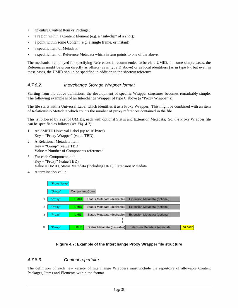
Page 83
• an entire Content Item or Package;
• a region within a Content Element (e.g. a “sub-clip” of a shot);
• a point within some Content (e.g. a single frame, or instant);
• a specific item of Metadata;
• a specific item of Reference Metadata which in turn points to one of the above.
The mechanism employed for specifying References is recommended to be via a UMID. In some simple cases, theReferences might be given directly as offsets (as in type D above) or as local identifiers (as in type F); but even inthese cases, the UMID should be specified in addition to the shortcut reference.
4.7.8.2. Interchange Storage Wrapper format
Starting from the above definitions, the development of specific Wrapper structures becomes remarkably simple.The following example is of an Interchange Wrapper of type C above (a “Proxy Wrapper”):
The file starts with a Universal Label which identifies it as a Proxy Wrapper. This might be combined with an itemof Relationship Metadata which counts the number of proxy references contained in the file.
This is followed by a set of UMIDs, each with optional Status and Extension Metadata. So, the Proxy Wrapper filecan be specified as follows (see Fig. 4.7):
1. An SMPTE Universal Label (up to 16 bytes)Key = “Proxy Wrapper” (value TBD).
2. A Relational Metadata ItemKey = “Group” (value TBD)Value = Number of Components referenced.
3. For each Component, add .....Key = “Proxy” (value TBD)Value = UMID, Status Metadata (including URL), Extension Metadata.
4. A termination value.
“Group” Component Count
1
2
3
n
Status Metadata (desirable) Extension Metadata (optional) UMID “Proxy”
“Proxy Wrap”
Status Metadata (desirable) Extension Metadata (optional) UMID “Proxy”
Status Metadata (desirable) Extension Metadata (optional) UMID “Proxy”
End code Status Metadata (desirable) Extension Metadata (optional) UMID “Proxy”
Figure 4.7: Example of the Interchange Proxy Wrapper file structure
4.7.8.3. Content repertoire
The definition of each new variety of interchange Wrappers must include the repertoire of allowable ContentPackages, Items and Elements within the format.

Page 84
This definition should be contained within the Registry entry for the label which identifies the Wrapper type.
4.7.8.4. Data model
In the analysis of responses to the First Request for Technology, it was realized that several of the responses to therequest for a “Rich Wrapper” (now called the Complex Content Package) offered complete systems whosecapabilities overlapped. Although reconciliation of these systems into a single system might be achieved, theresulting system would be of such wide scope that the process of standardization, and implementation of theresulting standard, would take a very long time. This does not meet the TFHS goal of selecting a Wrapper formatwhich can be standardized and deployed in the near future.
At the same time, it was clear that all responses used startlingly-similar data models which described “programs” asa combination of “tracks”, and made references to “media data” which is divided into “chunks”, described by“hints”, incorporating “effects” which are controlled by a set of “tweaks” and so on (this is intentionally a mixtureof terminology).
There was renewed agreement to define an overall data model which is adequate for all known existing tasks and isextensible to admit new applications and definitions. It is expected that every proposed system would be mappedonto this model, either directly or through the use of translators.
A large part of this data model is simply the creation of a glossary of terms for Complex Content Packages – whichis a subset of the task of creating the Metadata Dictionary with a “vendor-neutral” vocabulary.
In addition to this vocabulary, terminology is needed to describe the logical structure of the data model. TheDAVIC terms of Content Package, Content Item, Content Item Element, plus the other defined terms in the FirstReport form the basis of this class of terminology. In many cases, this terminology is not just a set of words, butalso has a real existence as data inside files. It is therefore another class or sub-class of Relational Metadata andshould be addressed in the Metadata Dictionary.
4.8.Newly-identified work
The following items of work have been identified to be taken up by the SMPTE or other standards bodies; but theseitems have not yet been initiated.
4.8.1. Interchange Storage Wrapper
A Proposed Standard on an Interchange Storage Wrapper is required for interoperability between differentequipment. The work summarized in this document should be passed to the SMPTE for consideration as aStandard in P18.
4.8.2. Wrapper profiles and Content repertoires
As new examples of Concrete Wrappers are produced, they should be documented within the SMPTE Registry.
4.8.3. Metadata Sets
As specific Metadata Sets are identified, they should be documented within the SMPTE Registry.

Page 85
4.8.4. Essence format documentation
The SMPTE Registry should also be used as the machinery to document Essence formats precisely (for example,Video Rasters, Audio Packet formats, Graphics formats) and codify them for use within Wrappers.
To some extent, this has already been achieved in the context of data formats for SDTI (notably, for DV-basedContent Packages), and is underway for PCM Audio and for MPEG-2 Video Elementary Streams.
However, this approach to documenting Essence formats as stand-alone specifications should be pursued forprimary Essence types which will be encountered in the Streaming and Storage Wrappers identified above. Othertypes of Essence may be documented, but it is to be encouraged to convert these Essence types to primary types inorder to maximize interoperability.
4.8.5. Mapping onto transport mechanisms
Standards must be written to map the Wrappers described here onto the transport mechanisms called out in Section5. Several of these projects are under way; however, no proposals have been seen for documenting a StreamingWrapper format for transport over ATM.
4.9.Conclusions
Starting from the First Report on User Requirements, the Sub-Group started to search for a comprehensive solution,and in the process issued a first Request for Technology. Several responses were received, covering aspects of therequired technology, from established companies in both the computer and television industries. The responsesranged from discussions of specific items such as Unique Material Identifiers and Frame Index Tables for use insideWrappers, to complete solutions for specific applications such as multimedia presentation delivery, to specificationsfor data models and container formats that are in use today in the industry, within multiple products. Theseresponses were analyzed during repeated meetings, along with comparisons of existing practices in the industry anddiscussions on standards development efforts which have been continuing simultaneously.
No single response to the RFT covered all Requirements; however, in general, the sum of the responses on Streamformats covered most of the Stream requirements, and similarly the sum of those on Rich Wrapper formats coveredmost of the Complex Content Package requirements.
Not surprisingly, the various proprietary technologies submitted were not immediately fully interoperable to thedegree requested in the First Report. However, in their use of established practices such as the use of globally-unique identifiers, some of the responses were more amenable than others to limited modification to achieveinteroperation.
The final phase of the Sub-Group’s work was to issue a Second Request for Technology in search of one missingitem from the first response – the low-level, special-purpose, Storage Mechanism.
During the concluding meetings of the Sub-Group, it became clear that the technology to employ incomprehensively addressing the requirements does exist. However, it was not possible to complete thedocumentation of this technology within the scope of the Sub-Group. Instead, this should be taken up by theSMPTE following the plan below:
4.9.1. Work in progress
The following standardization activities are already under way in the SMPTE and in other organizations:

Page 86
Note: The SMPTE Committees mentioned in this section are active at the time of writing (July 98). However, the SMPTE is shortlygoing to change its Technology Committee structure to better absorb the work that will arise from the Task Force's efforts, inwhich case the work will be undertaken by appropriate successor committees to those listed.
SMPTE PT20.07 Working Group on Metadata is processing several Proposed Standards for Metadata
SMPTE PT20.04 Working Group on Packetized Interconnect Technologies is balloting a proposed Standard on theSDTI-CP Streaming Wrapper.
SMPTE P18 Ad Hoc Group on Unique Material Identifier is creating a Proposed Standard based upon the existing“strawman” proposal.
SMPTE P18.27 Working Group on Editing Procedures is documenting the second RFT as “Requirements for aComplex Storage Mechanism”.
SMPTE P18.27 Working Group on Editing Procedures is also creating a Proposed Standard for a format of a“Complex Content Package”.
SMPTE P18.27 Working Group on Editing Procedures is also working on a revision of SMPTE 258M Interchange ofEdit Decision Lists.
SMPTE M21.21 Working Group on Content Formatting and Authoring has formed an Ad Hoc group on DVD Authoring.
NCITS T11 Standards Committee on Fibre Channel (formerly ANSI X3T11) is documenting the FC-AV Containeras part of a Proposed Standard for Fibre Channel Audio/Video.
WG SC-06-01 Networks for Audio Production of the AES Standards Committee is working towards standards forAudio file interchange.
ISO SC29 WG11 MPEG This group is working on an “Intermedia format” for storage of MPEG-4 data, to be included in version2 of ISO 14496-1 MPEG-4 Systems, which is planned to be published by the end of 1999.
4.9.2. Which documents to hand overNote: The SMPTE Committees mentioned in this section are active at the time of writing (July 98). However, the SMPTE is shortly
going to change its Technology Committee structure to better absorb the work that will arise from the Task Force's efforts, inwhich case the work will be undertaken by appropriate successor committees to those listed.
The work summarized here and in the references on the Unique Material Identifier (UMID) will be passed to theSMPTE P18.x Ad Hoc Group on Unique Material Identifiers.
A Proposed Standard on SDTI Content Packages will be studied by the SMPTE P18 Ad Hoc Group on the SDTI-CP Wrapper.
The proponents of an Advanced Streaming Format are encouraged to formulate a proposed Standard forconsideration by a new Working Group within SMPTE P18.
The proponents of the Structured Storage mechanism are encouraged to formulate a proposed Standard forconsideration by the Working Group on Editing Procedures within SMPTE P18.
4.9.3. Note on proprietary technology
Considering the importance of Wrappers to the industry as a whole, it is clear than there is no place in the output ofthe Task Force for the selection of proprietary technologies. This is so much so that the SMPTE’s usual rules foraccepting technology for standardization cannot apply. The TFHS specifically recommends full documentation ofthe technologies considered here and conformance to the following guidelines.
To be standardized, any technologies must be open in these respects:
• existing implementations must be freely licensable;
• technologies must be documented sufficiently to permit new implementations from the ground up, without fee;
• a due-process standards body must have control of the specification in the future.
The Sub-Group also recommends compliance-testing by an external organization.

Page 87
5.5. Networks and Transfer ProtocolsNetworks and Transfer Protocols
5.1.Introduction
There is an increasing use of systems which apply packetization to video, audio and all data types. Interoperability,or simply data exchange in the form of files and streams between different systems, is a strong requirement.
To meet the demand for interoperability, a Reference Architecture (RA) for Content transfers is recommended. TheRA recommends interfaces as well as file transfer protocols, protocols for real-time streaming of video, audio andall data types, and methods for file system access. Existing standards are recommended if available, while areasrequiring future developments and standardization are identified.
5.1.1. File transfer and streaming
File transfer involves the moving or copying of a file, with the dominant requirement that what is delivered at thedestination is an exact bit-for-bit replica of the original; retransmission of parts of the file initially found to suffererrors will be used to achieve this. Although the transfer may often be required to take place at high speed, therewill be no demand that it should take place at a steady rate, or be otherwise synchronized to any external event orprocess.
Streaming is the transfer of television programme material over a transport technology from a transmitter to one ormore receivers, such that the mean reception frame-rate is dictated by the sending frame-rate. The transmitterplays out the material without receiving feedback from the receivers; consequently, there is no capability for flowcontrol or for the re-transmission of lost or corrupt data. It is a continuous process in which the transmitter“pushes” programme material to receivers that may join or leave the stream at any time. The transmission frame-rate is not necessarily equal to the material’s original presentation frame-rate, thus allowing faster- or slower-than-real-time streaming between suitably-configured devices.
5.1.2. Quality of Service considerations
Ensuring that the needs of file transfers and streaming are met, in particular their respective dominant requirementsas described above, requires the definition and allocation of “Quality of Service” (QoS) parameters. Some transportsystems have implied and fixed QoS values, while others have values obtained by configuration or negotiationbetween users and the transport system. The latter is particularly the case with transport systems that allow thesharing of common resources (such as bandwidth) between multiple users with disparate QoS needs. This isnecessary so that changes in the total loading on available resources, for example when a new user joins existingsharers of the transport mechanism, do not adversely affect the QoS of users already present. In some systems, thetime needed for QoS negotiation is itself a QoS parameter, but this is beyond the scope of this document.
Major QoS parameters therefore are:
• bandwidth (which may be expressed as peak and average bit-rates);
• bit error rate;
• jitter and delay (latency);
• access set-up time.

Page 88
5.1.3. Reference Architecture
The concept of a Reference Architecture (RA) is useful for designers and users of Content in production anddistribution facilities. Fig. 5.1 illustrates the domain in which the RA is applied.
GUI
Transport, Network Stack
GUI
Application
Vendor specific
Data transfer compatible
RA
do
mai
n R
A d
om
ain
API compatible
Protocol compatible
Data compatible
Interoperability domains
Transport, Network
Stack
Content Transfer File Formats
Metadata Control, Access
Application
Content Transfer File Formats
Metadata Control, Access
Figure 5.1: Interoperability domains.
5.2.File transfer methods
File transfer entails the asynchronous, error-free transfer of Content, either point-to-point or point-to-multipoint. Insome applications, it may be necessary to specify QoS parameters for the transfer (e.g. a specified maximum bit-rateto avoid network congestion).
Four file transfer protocols are considered in this document:
• Universal FTP (based on TCP/IP);
• Point-to-multipoint transfers using the eXtended Transfer Protocol (XTP);
• Fast file transfer (methods which use hardware or lightweight software protocols over Fibre Channel, ATMand other transports);
• An enhanced version of FTP, called FTP+.

Page 89
Also, a method to initiate the file transfer is specified. NFS – a widespread and standardized file system accessmethod – is recommended, even though it may not provide the high-performance file system access that is required.The definition of an enhanced file system access method may be necessary in the future.
Annex E.2 gives more details about how file transfer is achieved over these and other transports.
Figure 5.2 illustrates the file transfer methods which depend on application spaces.
Also, a file system access (NFS) and a method to initiate the file transfer are specified.
Local Campus,City WAN
Distance
100Mbit/s
10Mbit/s
Transfer Rate
Fast file transfer methods
FTP / TCP & FTP+ / XTP
based transfers
NFS-based file access
Figure 5.2: File transfer / access application spaces.
5.3.Streaming methods
The required characteristics of streamed Content are:
• the “bounded quality” of the received signal 6;
• the received quality is directly related to the QoS of the link and any Forward Error Correction;
• isochronous / synchronous links or Time Stamps.
Examples of transports / protocols capable of supporting streaming are:
• IP;
6 There is usually no return path to request a retransmission, so the receiver must make the best of received data. ,Methods which do
use a return path for retransmission of packets require buffering and, consequently, they insert a delay.

Page 90
• ATM;
• SDI / SDTI;
• Fibre Channel;
• IEEE 1394;
• Dedicated purpose:
– ANSI 4-40 (AES / EBU);
– ITU-T T1, T3, E1, E3, ISDN;
– DVB ASI, SSI.
Annex E.3. gives more details about how streaming is achieved over these and other transports.
Figure 5.3 maps various application spaces to these streaming transports.
Internet, Int ranet, Browse
Distribution SD & HD
Production
Local Campus, City WAN
1394, FC, AES/EBU
(Distributed Production) SDI / SDTI
ATM
Dedicated Purpose (DTV, DVB, Sat, T1,T3...)
IP-Streaming
Streaming Technology Application Spaces
Qua
lity
Distance
Figure 5.3: Streaming Transports and their application space mapping
5.4.Recommended transport systems for Content
Recommended interfaces and networks include SDTI, Fibre Channel, Ethernet and ATM. While it is recognizedthat any of these technologies could be used for streaming within a broadcast studio, SDTI is currently (July 1998)recommended for streaming:
• Fibre Channel is recommended for fast / large file transfers;
• ATM is recommended for wide-area network file and stream transfers.

Page 91
Note: Ethernet was not investigated in great detail by the Sub-Group but, due to its wide availability and complete standardization, itmay be used as a general-purpose, low-performance, file transfer mechanism.
5.4.1. Serial Data Transport Interface (SDTI)
An additional layer above SDI (ITU-R BT.656, SMPTE 259M) has been defined to enable the transport ofpacketized data. This layer is called SDTI and has been standardized as SMPTE 305M.
SDTI is a universal transport layer which describes in detail the packetization and basic signaling structure for thedata to be transported. The use of the underlying SDI interface determines the technical capabilities of SDTI. Forexample:
• SDI is a unidirectional interface, making SDTI a unidirectional transport system per connection. To enable there-transmission of corrupted data, an additional “control” data path from destination to source will be neededto signal the requirement. SDI / SDTI should therefore be used primarily for streaming and not forconventional file transfers 7, as described in Section 5.2.
• SDI is a point-to-point interface and defines the bit-rate (e.g. 270/360 Mbit/s), jitter, delay and loss, whichconstrains the SDTI layer. To overcome the point-to-point restrictions, addressing capabilities are embeddedin the SDTI header and may be used in the future for dynamic routing.
• SDI is a synchronous interface; SDTI payloads can therefore be easily synchronized to the TV environment.This capability makes SDTI suitable for use in studio applications for the streaming of Content in real-time andfaster-than-real-time, and it also facilitates multiplexing.
All applications using SDTI as a transport require individual documentation.
5.4.2. ATM
ATM is a network technology for use in local and wide-area applications, accommodating a wide range of QoSrequirements for the transport of data, voice and video traffic over a common network infrastructure. Payload datais encapsulated in 53-byte containers (ATM cells). Each cell contains a destination address and can be multiplexedasynchronously over a link.
Connections through ATM networks (virtual circuits – VCs) can be pre-configured (Permanent Virtual Circuits –PVCs) or established on demand (Switched Virtual Circuits – SVCs) using standard protocols. A Quality ofService “contract” may be defined for each VC.
5.4.2.1. File transfer over ATM
File transfer over ATM is achieved through its capability to transport IP. This can be achieved through one of thefollowing protocols:
• Classical IP over ATM (IETF RFC1577);
• LAN emulation (LANE) (ATM Forum 94-0035);
• Multi-protocol over ATM (MPOA) (ATM Forum 96-0465);
• Multi-protocol Label Swapping (MPLS) (IETF Draft).
• Streaming over ATM
ATM is suitable for Content streaming in both the local and wide area. ATM provides QoS guarantees and error-correction capabilities. In order to meet the jitter and error-rate requirements of professional broadcast studio
7 There are methods under discussion within the SMPTE and the IETF for the transfer of files over unidirectional links.

Page 92
applications, engineering guidelines for the transportation of streams are necessary. Such guidelines wouldidentify, for example, the ATM network characteristics that must be supported by devices for streaming over ATM.
Synchronization between transmitting and receiving devices is achieved through the transport of timing referenceswithin the stream. ATM’s scalability, bandwidth efficiency and support for multiple traffic types make it a suitablechoice for streaming Content between studios over the wide area. International standards exist which define howthe MPEG-2 Transport Stream is streamed over ATM.
5.4.3. Fibre Channel
Fibre Channel is a network that is suited for use in broadcast studio applications. It has been accepted as the high-performance computer peripheral interconnect. It is also being used as a building / campus-wide high-speednetwork.
In broadcast applications, Fibre Channel is being used by the vendors of video disk recorders as a studio packetnetwork (using IP) and for shared storage attachment (using SCSI protocol). Standards exist to define the transportof IP packets over Fibre Channel.
Commonly-available Fibre Channel links (1 Gbit/s gross) support payload rates of about 800 Mbit/s (a proposedFast Fibre Channel transfer protocol enables a net bit transfer rate of up to 760 Mbit/s).
Fibre Channel solutions are limited to local-area transfers and an FC / SCSI-based solution will not be as flexible asone based on IP routing, but has the advantage of higher performance. Fibre Channel offers limited WANfunctionality.
5.4.3.1. File transfers over Fibre Channel
Fibre Channel may be used for FTP transfers using IP over its FC-4 layer. The alternative Fast File Transfershould follow the rules defined in the Fibre Channel Audio / Video (FC-AV) standard presently under developmentby the NCITS T11 group. To allow a predictable transfer time, fractional bandwidth capabilities must be availablefrom Fibre Channel component suppliers and implementers. For very fast transfers, therefore, transport protocolsimplemented in hardware are required.
5.4.3.2. Streaming over Fibre Channel
The Fibre Channel System (FCS) is designed for asynchronous transport but can also support synchronous transportby embedding timing references within the stream and using FCS Class-4 (fractional bandwidth) – see the sectionabove.
5.4.4. IEEE 1394-1995 high-performance serial bus
The IEEE 1394 bus was designed to support a variety of digital audio / video applications in a desktopenvironment. The version encountered in this environment relates to a specific cable and connector type, and islimited to cable lengths of about 4.5 m. Some companies have announced cables which work up to 100 m.
The physical topology of IEEE 1394 is a tree or daisy-chain network with up to 63 devices, which need not includea dedicated bus manager. Devices act as signal repeaters; the physical connections between nodes are made with asingle cable that carries power and balanced data in each direction.
The base data-rate for the IEEE 1394 cable environment is 98.304 Mbit/s, and signaling rates of 196.608 Mbit/sec(2X) and 393.216 Mbit/s (4X) have been defined.
Page 93
It is noted that different and incompatible protocols exist (CAL and AVc). Harmonization is strongly encouragedthrough communication with EIA-R4.
5.4.4.1. File transfers over IEEE 1394
Unlike most other Data Link protocols, IEEE 1394 provides the capability for isochronous as well as asynchronoustransmission. This capability has a significant impact on how IP is supported. The IP1394 working group of theIETF is working on an architecture document and appropriate protocol documents for the usage of these link layerproperties. Both IPv4 and IPv6 will be addressed.
5.4.4.2. Streaming over IEEE 1394
The isochronous mode of operation provides a streaming capability. In addition to the absence of confirmation, theprincipal difference from the asynchronous mode is QoS: isochronous datagrams are guaranteed to be deliveredwith bounded latency. Bandwidth for isochronous data transport (up to about 66% of the total) is reserved oninitialization and after any change in the network configuration.
5.5.Other transport systems
Other transport systems are available which may well be suitable in certain instances. These include GigabitEthernet, HIPPI, HIPPI-6400 and other IP-based transport systems. However, system implementers are advised thatthese alternative systems were not considered by the Task Force and their capabilities should be compared to thecriteria for data exchange described in this document. The requirements for file transfer are in general more likelyto be met than the requirements for streaming.
5.6.Bridging and Tunneling
Bridging is the transfer of payload between different transport mechanisms such as the moving of MPEG-TS fromSDTI or Fibre Channel to ATM (often needed between LANs and WANs).
Tunneling is a way of transporting a complete interface data structure, including payload, through anotherinterface; for example, IP over SDTI. IP multicast can then be used to transport both Data Essence and Metadatawhich are associated with the SDTI Audio / Video Essence carried in the main SDTI programme.
Both methods are discussed in Annex E.
5.7.Recommendations for future work
5.7.1. File transfers
To meet all requirements for file transfers, the implementation of an enhanced FTP (i.e. FTP+) over the eXpressTransfer Protocol (XTP) is recommended. The FTP+ profiles listed in this document are merely requirements andare neither developed nor standardized. The development and standardization of FTP+ and XTP has started in theSMPTE. Chunking for files also needs consideration by the SMPTE.
The FC-AV committee is working on a standard for a high-performance file transfer protocol. The completion ofthis work is of great importance and should be actively encouraged by the EBU and the SMPTE. It is important tocommunicate to manufacturers the requirement for an early implementation of this standard into products, and toencourage further liaison with the FC-AV Group.

Page 94
A method of setting up and determining the file transfer capabilities between different devices needs to bestandardized, probably in the form of a recommended practice.
End-to-end resource control and bandwidth management, when performing file transfer or streaming, is notaddressed in the Reference Architecture. This larger type of interoperability should be a long-term goal. However,the standards addressed in the Reference Architecture will provide much utility even without a complete SystemsArchitecture
5.7.2. Streaming / mapping
Concerning streaming recommendations, the previously mentioned FC-AV protocol is also suitable for asynchronous real-time / streaming data transport. An implementation of this is presently not available but of greatimportance. It is important to communicate to manufacturers the requirement for an early implementation of thisstandard into products, and to encourage further liaison with the FC-AV Group.
The streaming of Content in an interoperable way requires detailed information about the data structure of theContent to be streamed, and a method of how the data structure is mapped into the transport mechanism. In thisdocument, the so-called mapping tables which describe the required Content mappings need to be finalized. Itshould be stated that, for a given interface (transport mechanism), only one kind of mapping for a given Contentshould be standardized, in order to avoid multiple standards for the same purpose. Work on several mappingdocuments is ongoing, proposed or required.
The SMPTE is already working on a draft proposal for tunneling IP over SDTI links. It is also working on non-conventional file transfer over SDTI links, as part of a Generic Wrapper structure.
5.7.3. Standards for mapping the Content / containers into transportmechanisms
The following table gives an overview of Completed, Ongoing, Proposed and Required mappings betweencontainers and transport technologies. Cells which are not filled out are found to be not applicable or are notrequired in the short term.
Table 5.1: Mapping standards which are required to be developed and standardizedfor the Container / Transport technology.
Application/
TransportTechnology
ITU-R BT601Uncompressedbaseband video
ContentPackage
DV(IEC
61834)
DV-Based25/50
(Proposed)
M-JPEG(23)
ComponentCoded
(ITU-T, ETSI)
MPEG-2TS
(ISO13818)
SNF(Sony)
AAF / ASF22
(SMPTE)
SDI (SMPTE) C1
SDTI (SMPTE) C5 O18 P12 P3 R R P17 R8 R
FC-AV transport 19
(ANSI)O2 R20 O2 R R P2 R
1394 (Firewire)(IEEE)
R P15 R R
ATM (ITU) R P16 P16 R C13 C4 R
IP (IETF) R R C6
PDH (ITU) C14 C9
SDH (ITU) R C10
DVB ASI,SSI,SPI(ETSI)
C11

Page 95
Notes to Table 5.1
1. TU-R BT.656 (SMPTE259M).
2. NCITS T11 FC-AV (Project 1237-D).
3. SMPTE Proposed Standard: Data Structure for DV-based Compressed Systems over Serial Digital Transport Interface (SDTI).
4. ITU-T J.82 MPEG-2 -TS in ATM.
5. SMPTE 305M (with code=00).
6. IETF RFC 2038 (MPEG-2 over IP).
7. SMPTE Proposed Standards: MPEG-2 Elementary Streams over the Serial Digital Transport Interface (SDTI).
8. Sony Native Format (SNF) in SDTI (publicly available document).
9. ETSI ETS-300 813 DVB Interfaces to PDH Networks.
10. ETSI ETS-300 814 DVB Interfaces to SDH Networks.
11. ETSI EN 50083-9 Interfaces for CATV / SMATV head-ends and similar professional equipment for DVB / MPEG-2 TransportStreams.
12. Draft SMPTE Specifications for DVCAM (IEC 61834) in SDTI.
13. ATM Forum af-vtoa- 0078.000 Circuit Emulation Service Interoperability Specification 2.0.
14. ITU-T J.81: Transmission of Component-Coded Digital Television Signals for Contribution-Quality Applications at the ThirdHierarchical Level of ITU-T Recommendation G.702.ETSI ETS 300-174: Digital coding of component television signals for contribution quality applications in the range 34 - 45 Mbit/s.
15. IEC 61833
16. SMPTE Proposed Standard for DV over ATM
17. SMPTE Proposed Standard for MPEG-2 TS over the Serial Digital Transport Interface (SDTI)
18. SMPTE Proposed Standard for Content Packages over Serial Digital Transport Interface (SDTI). This should include MPEG-2 -ES.
19. FC-AV standards activity includes a simple container, a fast file transfer protocol, and a streaming protocol.
20. MPEG-2 -ES need to be mapped into FC-AV simple container.
21. Wrappers are defined in the section on Wrappers and Metadata. These need to be transported over the recommended transportmechanisms
22. AAF / ASF over IP. For SDTI applications a mapping of IP over SDTI needs to be defined.
23. The M-JPEG container specification is not available yet and needs to be standardized.
Note: The MPEG-4 file format derived from Apple QuickTime needs to be considered in further standardization
5.7.4. Interfaces / networks
For streaming in a point-to-point and point-to-multipoint studio environment, use of the SDTI interface isrecommended. Further enhanced versions of SDTI should be investigated and standardized if necessary (thisincludes also the mappings of applications into SDTI).
Bridging of specific containers between different transport mechanisms needs to be developed. For example, thetransport between studios of DV-encapsulated-in-SDTI requires bridging over ATM.
The implementation of the Fibre Channel FC-AV standard requires the development of new Fibre Channelfunctionalities in order to supporting functions such as bandwidth reservation. This work should be started as soonas possible and should be supervised by the EBU and SMPTE working groups.
The use of ATM and SDH / SONET in a WAN environment requires the implementation of mechanisms toovercome network jitter and wander, such that the resultant studio signal meets the ITU-R BT.656 and ITU-RBT.470 standards. Care should be taken in selecting equipment which ensures that the specifications mentionedabove are met. Guidelines and recommendations need to be developed to help users to determine the wander andjitter performance of the equipment used, as well as the overall functionalities (signaling, AAL, QoS, etc.) that are

Page 96
required for real-time streaming. Moreover, the TFHS has identified two different ATM adaptation layer methods(AAL 1 and AAL 5). A recommendation needs to be developed for the streaming of signals over ATM in acompatible way. Also, the development of a broadcast-specific adaptation layer (AALx) needs to be considered.

Page 97
Annex A: Abbreviations and specialized terms(Glossary)
Throughout this document specialized terms are used and defined as and when they occur. In addition to these,many of the words and acronymic abbreviations used are a jargon familiar to those in the television production, postproduction, broadcasting, telecommunications and computer industries. To assist readers who are unfamiliar withthese terms, an alphabetic listing of some of the more common ones is given below.-A-
A/D Analog-to-digital conversion.A/V Audio/Video or Audiovisual. This abbreviation is often used on the socketry of consumer equipment.AAL ATM adaptation layer. The AAL translates digital voice, images, video and data signals into the ATM cell
format and vice versa. Five AALs are defined:AAL1 supports connection-oriented services needing constant bit-rates and specific timing and delayrequirements (e.g. DS-3 circuit).AAL2 supports connection-oriented services needing variable bit-rates (e.g. certain video transmissionschemes).AAL3/4 supports both connectionless and connection-oriented variable rate services.AAL5 supports connection-oriented variable bit-rate data services. Also known as Simple and EfficientAdaptation Layer (SEAL).
Access setup time The amount of time taken to set up a transmission path between a source and a destination from themoment of commencing the connection process.
Adaptive predictor A predictor whose estimating function is made variable according to the short-term spectral characteristicsof the sampled signal. For ADPCM in particular, an adaptive predictor is a time-varying process thatcomputes an estimate of the input signal from the quantized difference signal.
Adaptive quantizing Quantizing in which some parameters are made variable according to the short-term statisticalcharacteristics of the quantized signal.
Address Translation The process of converting external addresses into standardized network addresses and vice versa. Itfacilitates the interconnection of multiple networks in which each have their own addressing scheme.
ADPCM Adaptive Differential Pulse Code Modulation. A compression algorithm that achieve bit-rate reductionthrough the use of adaptive prediction and adaptive quantization.
AES3-1985 The AES Recommended Practice for Digital Audio Engineering – a Serial Transmission Format for LinearlyRepresented Digital Audio Data. This is a major digital audio standard for serial interface transfer. It issubstantially identical to EBU Tech. 3250-E, CCIR Rec. 647, SP/DIF, IEC 958, EIA CP340 and EIA DAT.These standards describe a uni-directional, self- clocking, two-channel standard based on a single serialdata signal. The AES format contains audio samples up to 24 bits in length and non-audio data includingchannel status, user data, parity and sample validity. The differences between these standards lie inelectrical levels, connectors, and the use of channel status bits. The AES3 standard is better known as theAES /EBU serial digital audio interface.
Analog (video) signal A (video) signal, one of whose characteristic quantities follows continuously the variations of anotherphysical quantity representing information.
Analog transmission A type of transmission in which a continuously variable signal encodes an infinite number of values for theinformation being sent (compare with "digital").
Anisochronous The essential characteristic of a time-scale or a signal, such that the time intervals between consecutivesignificant instants do not necessarily have the same duration or durations that are integral multiples of theshortest duration.
ANSI The American National Standards Institute is a US-based organization that develops standards and definesinterfaces for telecommunications systems.
API Application Programming Interface. A set of interface definitions (functions, subroutines, data structures orclass descriptions) which together provide a convenient interface to the functions of a subsystem andwhich insulate the application from the minutiae of the implementation.
Application A computer program designed to perform a certain type of work. An application can manipulate text,numbers, graphics or a combination of these elements.An application differs from an operating system (which runs a computer), a utility (which performsmaintenance or general-purpose chores) and a programming language (with which computer programs arecreated).
Page 98
Application layer The seventh and highest layer in the International Organization for Standardization's Open SystemsInterconnection (OSI) model. The application layer contains the signals sent during interaction between theuser and application, and that perform useful work for the user, such as file transfer.
ASCII American Standard Code for Information Interchange. A coding scheme that assigns numeric values toletters, numbers, punctuation marks and certain other characters. By standardizing the values used forthese characters, ASCII enables computers and computer programs to exchange information. Although itlacks accent marks, special characters and non-Roman characters, ASCII is the most universal character-coding system.
Asset An Asset is any material that can be exploited by a broadcaster or service provider. An asset couldtherefore be a complete programme file, or it could be a part of a programme, individual sound, images etc.
Asset transfer The transfer of an Asset from one location to anotherAsynchronoustransmission
A term used to describe any transmission technique that does not require a common clock between the twocommunicating devices, but instead derives timing signals from special bits or characters (e.g. start/stopbits, flag characters) in the data stream itself. The essential characteristic of time-scales or signals suchthat their corresponding significant instants do not necessarily occur at the same average rate.
ATM Asynchronous Transfer Mode. A form of digital transmission based on the transfer of units of informationknown as cells. It is suitable for the transmission of images, voice, video, and data.
ATM Layer The protocol layer that relays cells from one ATM node to another. It handles most of the processing androuting activities including: each cell's ATM header, cell muxing/demuxing, header validation, payload-typeidentification, Quality of Service specification, prioritization and flow control.
-B-
Back channel The segment of a two-way communications system that flows from the consumer back to the Contentprovider, or to a system component, to provide feedback.
Backbone The top level in a hierarchical network.Bandwidth The frequency range of an electromagnetic signal, measured in hertz (cycles per second). The term has
come to refer more generally to the capacity of a channel to carry information, as measured in datatransferred per second. Transfer of digital data, for example, is measured in bits per second.
Bandwidth reservation The process of setting aside bandwidth on a specific broadcast channel for a specific data transmission. AContent server application reserves bandwidth on a Microsoft Broadcast Router by calling themsbdnReserveBandwidth function. This function forwards the request to a Microsoft® BandwidthReservation Server. The server returns a unique reservation identifier if the bandwidth can be reserved.
Baseband Describes transmissions using the entire spectrum as one channel. Alternatively, baseband describes acommunication system in which only one signal is carried at any time. An example of the latter is acomposite video signal that is not modulated to a particular television channel.
Baud Number of bits per second, a measure of data-transmission speed. Baud was originally used to measurethe transmission speed of telegraph equipment but now most commonly measures modem speeds. Themeasurement is named after the French engineer and telegrapher, Jean Maurice-Emile Baudot.
BER Bit Error Ratio (or Rate).B-frame MPEG-2 B-frames use bi-directionally-interpolated motion prediction to allow the decoder to rebuild a
frame that is located between two reconstructed display frames. Effectively the B-frame uses both pastframes and future frames to make its predictions. B-frames are not used as reference frames but forfurther predictions. However, they require more than two frames of video storage in the decoder, which canbe a disadvantage in systems where low cost is of the essence. By using bi-directional prediction, B-frames can be coded more efficiently than P-frames, allowing a reduction in video bit-rate whilst maintainingsubjective video quality.
Bit A member selected from a binary set. “Bit” is a contraction of “binary digit”.Broadband A service or system requiring transmission channels capable of supporting rates greater than the Integrated
Services Digital Network (ISDN) primary rate (1.544 Mbit/s (e.g. USA) or 2.048 Mbit/s (e.g. Europe)).Broadband is also sometimes used to describe high-speed networks in general.
Broadcast In general terms, a transmission sent simultaneously to more than one recipient. There is a version ofbroadcasting used on the Internet known as multicast. In multicast, each transmission is assigned its ownInternet Protocol (IP) multicast address, allowing clients to filter incoming data for specific packets ofinterest.
Broadcast (Messages) Transmissions sent to all stations (or nodes, or devices) attached to the network.Broadcast Router A component that enables a Content server to send a data stream to a multiplexer or other broadcast output
device. A Broadcast Router calls a virtual interface to transmit a stream at the appropriate rate and in theappropriate packet format.
Broadcaster (ServiceProvider)
An organization which assembles a sequence of events or programs to be delivered to the viewer basedupon a schedule.
Buffer An area of storage that provides an uninterrupted flow of data between two computing devices.

Page 99
BWF Broadcast Wave File. The EBU has defined a file format which contains the minimum information that isconsidered necessary for all broadcast applications. The basic information, together with the audio data, isorganized as "Broadcast Wave Format" (BWF) files. From these files, using an object-oriented approach,a higher level descriptor can be used to reference other files containing more complex sets of informationwhich can be assembled for the different specialized kinds of applications.
-C-
CA Conditional Access. A system to control subscriber access to services, programs and events.CBO Continuous Bit-stream Oriented. Services which require an ordered and uninterrupted sequence of data to
represent them. PCM-coded video is an example of a CBO service.CBR Constant bit rate. A type of traffic that requires a continuous, specific amount of bandwidth (e.g. digital
information such as video and digitized voice).CCITT The Consultative Committee on International Telephony and Telegraphy, part of the ITU, develops
standards and defines interfaces for telecommunications systems.Cell A transmission unit of fixed length, used in cell relay transmission techniques such as ATM. An ATM cell
is made up of 53 bytes (octets) including a 5-byte header and a 48-byte data payload.Cell Relay Any transmission technique that uses packets of a fixed length. ATM, for example, is a version of cell relay
using 53-byte cells. Other versions use cells of a different length.CEPT The Conference on European Post and Telegraph is a European organization that develops standards and
defines interfaces for telecommunications systems.Channel A means of unidirectional transmission of signals between two points.CHAP Challenge Handshake Authentication Protocol.Chip-set Several integrated circuits (ICs) which work together to perform a dedicated task. Subsequent
development of the chip-set usually decreases the number of ICs needed, and often a single ICimplementation is achieved.
Chroma The color portion of the video signal that includes hue and saturation information. Hue refers to a tint orshade of color. Saturation indicates the degree to which the color is diluted by luminance or illumination.
Chunking The process of “chunking” converts a large file into two or more smaller ones.Circuit Switching A switching technique in which a dedicated path is set up between the transmitting device and the receiving
device, remaining in place for the duration of the connection (e.g. a telephone call is a circuit-switchedconnection).
Class In general terms, a category. In programming languages, a class is a means of defining the structure ofone or more objects.
Class Driver A standard driver provided with the operating system that provides hardware-independent support for agiven class of devices. Such a driver communicates with a corresponding hardware-dependent minidriver,using a set of device control requests defined by the operating system. These requests are specific to theparticular device class. A class driver can also define additional device control requests itself. A classdriver provides an interface between a minidriver and the operating system.
Client Generally, one of a group of computers that receive shared information sent by a computer called a serverover a broadcast or point-to-point network. The term client can also apply to a software process, such asan Automation client, that similarly requests information from a server process and that appears on thesame computer as that server process, or even within the same application.
Clock Equipment that provides a timing signal.Closed Captioning Real-time, written annotation of the currently displayed audio Content. Closed Captioning – mainly used in
525-line countries – usually provides subtitle information to hearing-impaired viewers or to speakers of alanguage other than that on the audio track.
Codec A combination of an encoder and a decoder in the same equipment.COM Component Object Model. An object-oriented programming model for building software applications made
up of modular components. COM allows different software modules, written without information about eachother, to work together as a single application. COM enables software components to access softwareservices provided by other components, regardless of whether they involve local function calls, operatingsystem calls or network communications.
Component (ElementaryStream)
One or more entities which together make up an event, e.g. video, audio, teletext.
Compression The process of reducing the number of bits required to represent information, by removing redundancy. Inthe case of information Content such as video and audio it is usually necessary to extend this process byremoving, in addition, information that is not redundant but is considered less important. Compressiontechniques that are used include: blanking suppression, DPCM, sub-Nyquist sampling, transform coding,statistical coding, sub-band coding, vector coding, run length coding, variable length coding, fractal codingand wavelet coding.
Connectionless A type of communication in which no fixed path exists between a sender and receiver, even during atransmission (e.g. packet switching). Shared media LANs are connectionless.
Connection-oriented A type of communication in which an assigned path must exist between a sender and a receiver before atransmission occurs (e.g. circuit switching). ATM networks are connection-oriented.

Page 100
Content Programme Content can be Video Essence, Audio Essence, Data Essence and Metadata. Content cantherefore include television programming, data and software applications.
Content provider A person or company delivering broadcast Content.CPU Central Processing Unit. In a personal computer, the CPU is the microprocessor which is the computer.CRC Cyclic Redundancy Check. A common technique for detecting errors in data transmission. In CRC error
checking, the sending device calculates a number based on the data transmitted. The receiving devicerepeats the same calculation after transmission. If both devices obtain the same result, it is assumed thetransmission was error-free. The procedure is known as a redundancy check because each transmissionincludes not only data but additional, redundant values for error checking.
CVD Cell Delay Variation. A measurement of the allowable variation in delay between the reception of one celland the next, usually expressed in thousandths of a second, or milliseconds (ms). Important in thetransmission of voice and video traffic, CDV measurements determine whether or not cells are arriving atthe far end too late to reconstruct a valid packet.
-D-
D/A Digital-to-analog conversion.Data Link layer The second of the seven layers in the International Organization for Standardization's Open Systems
Interconnection (OSI) model for standardizing communications. The data link layer is one level above thephysical layer. It is involved in packaging and addressing information and in controlling the flow of separatetransmissions over communications lines. The data link layer is the lowest of the three layers (data link,network and transport) that help to move information from one device to another. There is also a Data Linklayer in the EBU / SMPTE four-layer object model.
Data service A mechanism offered by a service provider for sending broadcast data to broadcast clients. Such data caninclude Programme Guide information, World Wide Web pages, software and other digital information.The data service mechanism can be any broadcast process.
Data streaming The data broadcast specification profile for data streaming supports data broadcast services that require astreaming-oriented, end-to-end delivery of data in either an asynchronous, synchronous or synchronizedway through broadcast networks. Data which is broadcast according to the data streaming specification iscarried in Programme Elementary Stream (PES) packets which are defined in MPEG-2 Systems.Asynchronous data streaming is defined as the streaming of only data without any timing requirements (e.g.RS-232 data).Synchronous data streaming is defined as the streaming of data with timing requirements in the sense thatthe data and clock can be regenerated at the receiver into a synchronous data stream (e.g. E1, T1).Synchronized data streaming is defined as the streaming of data with timing requirements in the sense thatthe data within the stream can be played back in synchronization with other kinds of data streams (e.g.audio, video).
Datagram One packet of information and associated delivery information, such as the destination address, that isrouted through a packet-switching network. In a packet-switching network, data packets are routedindependently of each other and may follow different routes and arrive in a different order from which theywere sent. An Internet Protocol (IP) multicast packet is an example of a datagram.
DAVIC Digital Audio VIsual Council. DAVIC has been convened along similar lines to MPEG but with no affiliationto a standards body; it therefore has the status of a world-wide industry consortium. Its purpose is toaugment MPEG and to collect system specifications for the delivery of a range of audio-visual serviceswhich can be applied uniformly on a world-wide basis.
DCT Discrete Cosine Transform. A DCT process basically involves dividing the picture up into 8 x 8 pixelblocks, then replacing the discrete luminance and chrominance values of each pixel by the amplitudes ofthe corresponding frequency components for the horizontal and vertical directions respectively. In this way,the information is transformed from the time domain to the frequency domain. No information is lost in thisprocess, except perhaps by the rounding of the last digit of the frequency coefficient values.
Delivery system The physical medium by which one or more multiplexes are transmitted, e.g. a satellite system, wide-bandcoaxial cable, fiber optics, terrestrial channel of one emitting point.
DEMUX Demultiplexer. A device that performs the complementary operation to that of a multiplexer.Descrambler A device that performs the complementary operation to that of a scrambler.Device A unit of hardware, for example a videotape machine or a server.Device class A group into which devices are placed for the purposes of installing and managing device drivers, and for
allocating resources.Device driver A software component that allows an operating system to communicate with one or more specific hardware
devices attached to a computer.Device object A programming object used to represent a physical, logical or virtual hardware device whose device driver
has been loaded into the operating system.DIF Digital InterFace. All the DV-based compression schemes share the so-called DIF structure which is
defined in the “Blue Book” (IEC 61834).Digital (transmission)channel
The means of unidirectional digital transmission of digital signals between two points.

Page 101
Digital connection A concatenation of digital transmission channels, switching and other functional units, set up to provide forthe transfer of digital signals between two or more points in a network, in support of a singlecommunication.
Digital demultiplexing The separation of a (larger) digital signal into its constituent digital channels.Digital multiplexing A form of time-division-multiplexing applied to digital channels by which several digital signals are combined
into a single (larger) digital signal.Digital signal A discretely-timed signal in which information is represented by a number of well-defined discrete values
that one of its characteristic quantities may take in time.Digital transmission The transmission of digital signals by means of a channel or channels that may assume, in time, any one of
a defined set of discrete states.Digital-S Matsushita trademark. This tape system is based on DV technology, and has a data-rate of 50 Mbit/s.Downstream One-way data flow from the head-end to the broadcast client.DPCM Differential Pulse Code Modulation. A process in which a signal is sampled, and the difference between
each sample of this signal and its estimated value is quantized and converted by encoding to a digitalsignal.
DSP Digital signal processor.DTS Data Time Stamp.DV Digital Video. A digital videotape format originally conceived for consumer applications.DVB Digital Video Broadcasting.DVB-C DVB framing structure, channel coding and modulation scheme for cable systems (EN 300 429).DVB-S DVB baseline system for digital satellite television (EN 300 421).DVB-T DVB baseline system for digital terrestrial television (EN 300 744).DVC Digital Video Cassette.DVCPRO, DVCPRO50 Matsushita trademarks. Based on DV technology and having a data-rate of 25 Mbit/s and 50 Mbit/s
respectively.DVD Digital Versatile (Video) Disk-E-
EBU European Broadcasting Union. Headquartered in Geneva, Switzerland, the EBU is the world's largestprofessional association of national broadcasters. Following a merger on 1 January 1993 with theInternational Radio and Television Organization (OIRT) – the former association of Socialist Blocbroadcasters – the expanded EBU has 66 active members in 49 European and Mediterranean countries,and 51 associate members in 30 countries elsewhere in Africa, the Americas and Asia.
ECM Entitlement Control Message.Enhancement A multimedia element, such as a hypertext link to a World Wide Web page, a graphic, a text frame, a sound
or an animated sequence, added to a broadcast show or other video programme. Many such elements arebased on Hypertext Markup Language (HTML).
EPG Electronic Programme Guide.Error ratio [error rate] The ratio of the number of digital errors received in a specified period to the total number of digits received
in the same period.Error, digital error An inconsistency between a digit in a transmitted digital signal and the corresponding digit in the received
digital signal.ESCR Elementary Stream Clock Reference.ETR ETSI Technical Report.ETS European Telecommunication Standard.ETSI European Telecommunications Standards Institute.-F-
FEC Forward error correction. A system of error correction that incorporates redundancy into data so thattransmission errors can, in many cases, be corrected without requiring retransmission.
Field In broadcast television, one of two sets of alternating lines in an interlaced video frame. In one field, theodd-numbered lines of video are drawn on the screen; in the other, the even-numbered lines are drawn.When interlaced, the two fields combine to form a single frame of on-screen video.
File An organized collection of related records, accessible from a storage device via an assigned address. Therelationship between the records and the file may be that of common purpose, format or data source, andthe records may or may not be sequenced.

Page 102
Frame (a) In broadcast television, a single screen-sized image that can be displayed in sequence with otherslightly different images to animate drawings. In the case of NTSC video, a video frame consists oftwo interlaced fields of 525 lines; NTSC video runs at 30 frames per second. In the case of PAL orSECAM video, a video frame consists of two interlaced fields of 625 lines; PAL and SECAM video runat 25 frames per second. By way of comparison, film runs at 24 frames per second.
(b) Variable-length packet of data used by traditional LANs such as Ethernet and Token Ring, as well asWAN services such as X.25 or Frame Relay. An edge switch will take frames and divide them intofixed-length cells using an AAL format. A destination edge switch will take the cells and reconstitutethem into frames for final delivery.
FTP File Transfer Protocol. A protocol that supports file transfers to and from remote systems on a networkusing Transmission Control Protocol / Internet Protocol (TCP/IP), such as the Internet. FTP supportsseveral commands that allow the bi-directional transfer of binary and ASCII files between systems.
FTP+ FTP+ is an enhanced version of FTP, and uses the same base set of commands. FTP+ includes newcommands that enable traditional features and which also provide the ability to embrace network protocolsother than IP.
-G-
Gbit/s Gigabit per second. A digital transmission speed of billions of (i.e.109) bits per second.Genre A category of broadcast programs, typically related by style, theme or format, e.g. TV movies or television
series.GoP Group of Pictures. An MPEG-2 GoP begins with an I-frame and extends to the last frame before the next
I-frame. The GoP sequence is known as an open GoP – the last frame in the GoP uses the first frame ofthe next GoP as a reference. Another type of GoP is a closed GoP, which has no prediction links to thenext GoP and, by definition, always ends in a P-frame.
GSM Global System for Mobile communication.Guaranteed bandwidth Bandwidth that is reserved only if the requested bandwidth is available for the requested period. Once
reserved, such bandwidth can be relied upon to be available.-H-
HDTV High Definition TeleVision. Television that is delivered at a higher screen resolution than that of NTSC,PAL or SECAM.
Head-end The origin of signals in a terrestrial, cable, satellite or network broadcast system. In BroadcastArchitecture, the server infrastructure that gathers, coordinates and broadcasts data is generally located atthe broadcast head-end.
HEX Hexadecimal. A numbering system with a base of 16 (binary numbers have a base of 2, and decimalnumbers have a base of 10). In HEX notation, the decimal numbers 0 to 9 are extended by the addition ofthe uppercase letters A to F, i.e. 0, 1, 2, 3, 4, 5, 6, 7, 8, 9, A, B, C, D, E, F (which is equivalent to thenumbers 0 to 15 in decimal notation).
Host A device where one or more modules can be connected, e.g. a VTR, a PC ...HTML Hypertext Mark-up Language. A mark-up language used to create hypertext documents that are portable
from one platform to another. HTML files are text files with embedded codes, or mark-up tags, that indicateformatting and hypertext links. HTML is used for formatting documents on the World Wide Web.
HTTP Hypertext Transport Protocol. The underlying, application-level protocol by which World Wide Web clientsand servers communicate on the Internet.
-I-
ID IdentifierIDL Interface Definition Language. Used to describe interfaces that client objects call and object
implementations provide. It is a purely descriptive language which has mappings provided for severalprogramming languages such as C++, C and Java. It has the same lexical rules as C++.
IEC International Electrotechnical Commission. Based in Geneva, the IEC is the world organization thatprepares and publishes international standards for all electrical, electronic and related technologies.
IEEE (US) Institute of Electrical and Electronic Engineers. The world's largest technical professional society,with more than 320,000 members. The technical objectives of the IEEE focus on advancing the theory andpractice of electrical, electronic and computer engineering, and computer science.
IETF Internet Engineering Task Force. The IETF is a large open international community of network designers,operators, vendors and researchers concerned with the evolution of the Internet architecture and thesmooth operation of the Internet. It is open to any interested individual.
I-Frame Intra-coded Frame. I-frame pictures make use only of information already contained within that frame.They are not dependent on other frames and can act as the starting point to enable decoders to beginworking on a GoP containing a sequence of other types of frame. The amount of compression achievableis typically less than for the other types of frame.
IIOP Internet Inter-ORB Protocol. See ORB.Interactive television The interactive combination of a video programme and multimedia enhancement elements such as
hypertext links, graphics, text frames, sounds and animation.

Page 103
Interface The common boundary point where two elements connect so that they can work with one another. Incomputing, the connection between an application and an operating system or between an application and auser (the user interface) are examples of an interface. In C++ programming, an interface is a collection ofrelated methods exposed by a given class of objects. These methods are procedures that can beperformed on or by those objects.
Interlacing A video display technique, used in current analog televisions, in which the electron beam refreshes(updates) all odd-numbered scan lines in one field and all even-numbered scan lines in the next.Interlacing takes advantage of both the screen phosphor's ability to maintain an image for a short timebefore fading and the human eye's tendency to average subtle differences in light intensity. By refreshingalternate lines, interlacing halves the number of lines to update in one screen sweep. An alternative videodisplay technique, used in computer monitors, is progressive scanning. In progressive scanning, the imageis refreshed one line at a time.
Internet Generically, a collection of networks interconnected with routers. "The Internet" is the largest suchcollection in the world. It has a three-level hierarchy composed of backbone networks, mid-level networksand stub networks.
IOR Interoperable Object Reference.IP Internet Protocol. The primary network layer of Internet communication, responsible for addressing and
routing packets over the network. IP provides a best-effort, connectionless delivery system that does notguarantee that packets arrive at their destination or that they are received in the sequence in which theywere sent.
IP Address An identifier for a network node; expressed as four fields separated by decimal points (e.g. 136.19.0.5.); IPaddress is site-dependent and assigned by a network administrator.
IPCP Internet Protocol Control Protocol.IP-over-ATM The adaptation of TCP/IP and its address resolution protocol for transmission over an ATM network. It is
defined by the IETF in RFCs 1483 and 1577. It puts IP packets and ARP requests directly into protocoldata units and converts them to ATM cells. This is necessary because IP does not recognize conventionalMAC-layer protocols, such as those generated on an Ethernet LAN.
IS Interactive Service.ISDN Integrated Services Digital Network. A type of dial-up service. Data can be transmitted over ISDN lines at
speeds of 64 or 128 kbit/s, whereas standard phone lines generally limit modems to top speeds of 20 to 30kbit/s.
ISO International Organization for Standardization, based in Geneva.Isochronous A term used to describe signal-timing techniques that require a uniform reference point (usually embedded
in the data signal).ITU International Telecommunication Union, part of the United Nations, based in Geneva.-J-
Java An object-oriented, platform-independent computer programming language developed by SunMicrosystems. The Applet subclass of Java can be used to create Internet applications.
Jitter Short-term non-cumulative variations of the significant instants of a digital signal from their ideal positions intime.
Jitter, delay, latency See Latency
-K-
kbit/s kilobits per second. A digital transmission speed expressed in thousand of bits per second.-L-
LAN Local Area Network. A network dispersed over a relatively limited area and connected by a communicationslink that enables each device on the network to interact with any other.
LAN Emulation The process of implementing enough of the media access control layer protocol of a LAN (e.g. Ethernet orToken Ring) to allow existing higher layer protocols (and applications) to be used unchanged over anothernetwork, such as an ATM network.
Latency The time delay inherent in a manipulative process. In particular, the time that it takes to process an inputbitstream through a compression and decompression process. Buffering and transmission can be majorcontributors to processing delays.
Link Any physical connection on a network between two separate devices, such as an ATM switch and itsassociated end point or end station.
Log on To provide a user name and password that identifies you to a computer network.LSB Least Significant Bit. In any related grouping of bits (i.e. a word), there will be one which quantifies the
zeroth power of 2 (i.e. the value is 0 or 1). This bit is the LSB of the word.Luminance A measure of the degree of brightness or illumination radiated by a given source. Alternatively, the
perceived brightness component of a given color, as opposed to its chroma.-M-
MAA MPEG ATM Adaptation.MAC Media Access Control.
Page 104
MAN Metropolitan area network.Master clock A clock that is used to control the frequency of other clocks.Mbit/s Megabits per second. A digital transmission speed expressed in millions of bits per second.MBONE Multicast backbone. A virtual, multicast-enabled network that works on top of the Internet. The most
popular application for the MBONE is video conferencing, including audio, video and whiteboardconferencing. However, the essential technology of the MBONE is simply multicast – there is no specialsupport for continuous media such as audio and video. The MBONE has been set up and maintained on aco-operative, volunteer basis.
Metadata Data describing other data.MIB Management Information Base.MIME Multipurpose Internet Mail Extensions.MJD Modified Julian Date.MMDS Microwave Multi-point Distribution Systems (or Multichannel Multi-point Distribution Systems). Also known
as wireless cable.MMI Man Machine Interface. The MMI of a door is its doorknob. That of a PC is a combination of keyboard,
mouse and monitor.Module A small device, not working by itself, designed to run specialized tasks in association with a host – for
example, a conditional access sub system, or an electronic programme guide application module – or toprovide resources required by an application but not provided directly by the host
MPEG Motion Picture Experts Group. MPEG-1 is a standard designed for video playback from CD-ROM. Itprovides video and audio compression at rates up to 1.8 Mbit/s. MPEG-2 refers to the ISO/IEC 13818standard, and it provides higher video resolutions and interlacing for broadcast television and high-definitiontelevision (HDTV). Both standards were created by the Motion Pictures Experts Group, an InternationalStandards Organization / International Telegraph and Telephone Consultative Committee (ISO/CCITT)group set up to develop motion video compression standards. The MPEG system makes use of threedifferent types of compressed video frames, (I, P and B frames), which are stored so as to enable temporalprediction of missing or incomplete frames as received by the decoder.
MPEG TS MPEG Transport Stream.MPI MPEG Physical Interface.MPLS Multi-protocol Label Swapping.MSB Most Significant Bit. In any related grouping of bits (i.e. a word), there will be one which quantifies the
largest power of 2. This bit is the MSB of the word.MTU Multiport Transceiver Unit.Multicast A point-to-many networking model in which a packet is sent to a specific address, and only those
computers that are set to receive information from this address receive the packet. On the Internet, thepossible IP multicast addresses range from 224.0.0.0 through 239.255.255.255. Computer networkstypically use a unicast model, in which a different version of the same packet is sent to each address thatmust receive it. The multicast model greatly reduces traffic and increases efficiency on such networks.
Multicast Messages A subset of “broadcast” in which a transmission is sent to all members of a pre-defined group of stations,nodes or devices.
Multimedia Online material that combines text and graphics with sound, animation or video, or some combination of thethree.
Multipoint Generally encountered in the term "point-to-multipoint" which describes a broadcast topography.MUX Multiplex or multiplexer. A stream of all the digital data carrying one or more services within a single
physical channel. In general terms, a multiplexer is a device for funneling several different streams of dataover a common communications line. In the case of broadcasting, a multiplexer combines multipletelevision channels and data streams into a single broadcast.
MVDS Multipoint Video Distribution System.-N-
NE Network Element.Network In computing, a data communications system that interconnects a group of computers and associated
devices at the same or different sites. A collection of MPEG-2 Transport Stream (TS) multiplexestransmitted on a single delivery system, e.g. all digital channels on a specific satellite or cable system.
NFS Network File System. This is defined in RFC 1813. File system access is different from file transfer, inthat Network File Systems generally employ a client-server model in which the server computer actually hasthe file system as local data. The client-host is allowed to “mount” the network file system to get access to
the directories and files as if they were locally available. Multiple clients are permitted to simultaneously“mount” the server's file system and get access to its Content.
NCITS National Committee for Information Technology Standards. NCITS T11 is responsible for standardsdevelopment in the areas of Intelligent Peripheral Interface (IPI), High-Performance Parallel Interface(HIPPI) and Fibre Channel (FC).
NNI Network-to-Network Interface. In an ATM network, the interface between one ATM switch and another, oran ATM switch and a public ATM switching system.

Page 105
NTSC National Television System Committee – which originated the NTSC standard for analog television signalsin North America, and which has also been adopted in Japan and parts of South America. The NTSCsystem is based on a power supply frequency of 60 Hertz (Hz) and can display 525 scan lines atapproximately 30 frames per second. However, non-picture lines and interlaced scanning methods makefor an effective resolution limit of about 340 lines. The bandwidth of the system is 4.2 Megahertz (MHz).
-O-
Object A computer programming term describing a software component that contains data or functions accessedthrough one or more defined interfaces. In Java and C++, an object is an instance of a object class.
Octet A group of eight binary digits or eight signal elements capable of representing 256 different values operatedupon as an entity (also known as a “word”).
Operating system Software responsible for controlling the allocation and usage of computer hardware resources such asmemory, CPU time, disk space and peripheral devices.
Opportunistic bandwidth Bandwidth granted whenever possible during the requested period, as opposed to guaranteed bandwidthwhich is actually reserved for a given transmission.
OSI Open Systems Interconnection. This refers to the ISO / OSI seven layer model for standardizingcommunications.
-P-
Packet A unit of information transmitted as a whole from one device to another on a network. In packet-switchingnetworks, a packet is defined more specifically as a transmission unit of fixed maximum size that consistsof binary digits representing both data and a header containing an identification number, source anddestination addresses, and sometimes error-control data.
Packet Switching A switching technique in which no dedicated path exists between the transmitting device and the receivingdevice. Information is formatted into individual packets, each with its own address. The packets are sentacross the network and reassembled at the receiving station.
PAL Phase Alternation by Line standard. The analog television standard for much of Europe – except France,Russia and most of Eastern Europe, which use SECAM. As with SECAM, PAL is based on a 50 Hertz(Hz) power supply frequency, but it uses a different encoding process. It displays 625 scan lines and 25frames per second, and offers slightly better resolution than the NTSC standard used in mainly in NorthAmerica and Japan. The PAL bandwidth is 5.5 Megahertz (MHz).
Partial Transport Stream(TS)
Bitstream derived from an MPEG-2 TS by removing those TS Packets that are not relevant to oneparticular selected programme, or a number of selected programs.
PCM Pulse Code Modulation. A process in which a signal is sampled, and each sample is quantizedindependently of other samples and converted by encoding to a digital signal.
PCR Programme Clock Reference.PDH Plesiochronous Digital Hierarchy.PDU Protocol Data Unit. A unit of information (e.g. a packet or frame) exchanged between peer layers in a
network.PES Packetized Elementary Stream.
P-frame MPEG-2 P-frames use a single previously-reconstructed frame as the basis for temporal predictioncalculations; they need more than one video frame of storage. Effectively the P-frame uses the nearestprevious frame (I or P) on which to base its predictions, and this is called forward prediction. P-frames
serve as the reference frame for future P- or B-frames, but if errors exist in a particular P-frame, they maybe carried forward to the future frames derived from them. P-frames can provide a greater degree of
compression than I-frames.Physical Layer The first of the seven layers in the International Organization for Standardization's Open Systems
Interconnection (OSI) model for standardizing communications. It specifies the physical interface (e.g.connectors, voltage levels, cable types) between a user device and the network.
PID Packet Identifier.Plesiochronous The essential characteristic of time-scales or signals such that their corresponding significant instants
occur at nominally the same rate, any variation in rate being constrained within specified limits. Two signalshaving the same nominal digit rate, but not stemming from the same clock, are usually plesiochronous.
PLL Phase Locked Loop.Plug and Play A design philosophy and set of specifications that describe changes to hardware and software for the
personal computer and its peripherals. These changes make it possible to automatically identify andarbitrate resource requirements among all devices and buses on a computer. Plug and Play specifies a setof application programming interface (API) elements that are used in addition to existing driverarchitectures.
Point-to-point A term used by network designers to describe network links that have only one possible destination for atransmission.

Page 106
Port Generally, the address at which a device such as a network interface card (NIC), serial adapter or paralleladapter communicates with a computer. Data passes in and out of such a port. In Internet Protocol,however, port signifies an arbitrary value used by the Transmission Control Protocol / Internet Protocol(TCP/IP) and User Datagram Protocol / Internet Protocol (UDP/IP) to supplement an IP address so as todistinguish between different applications or protocols residing at that address. Taken together, an IPaddress and a port uniquely identify a sending or receiving application or process.
PRBS Pseudo Random Binary Sequence.Predictor A device that provides an estimated value of a sampled signal, derived from previous samples of the same
signal or from a quantized version of those samples.Printf A symbol in the C programming language.Programme A concatenation of one or more events under the control of a broadcaster, e.g. a news broadcast,
entertainment show.PSI MPEG-2 Programme Specific Information (as defined in ISO/IEC 13818-1).PSK Phase Shift Keying.PSTN Public Switched Telephone Network.PTS Presentation Time Stamp.Push model A broadcast model in which a server sends information to one or more clients on its own schedule, without
waiting for requests. The clients scan the incoming information, save the parts they have been instructedto save, and discard the rest. Because the push model eliminates the need for requests, it eliminates theneed for a back channel from the client to the server. The push model contrasts with the pull model, inwhich each client requests information from a server. The pull model is more efficient for interactivelyselecting specific data to receive, but uses excessive bandwidth when many clients request the sameinformation.
PVC Permanent Virtual Circuit. A generic term for any permanent, provisioned, communications medium. Notethat PVC does not stand for permanent virtual channel. In ATM, there are two kinds of PVCs: permanentvirtual path connections (PVPCs) and permanent virtual channel connections (PVCCs).
-Q-
QAM Quadrature Amplitude Modulation.QoS Quality of Service. The ATM Forum, for example, has outlined five categories of performance (Classes 1 to
5) and recommends that ATM's QoS should be comparable to that of standard digital connections.QPSK Quadrature Phase Shift Keying.Quantizing A process in which a continuous range of values is divided into a number of adjacent intervals, and any
value within a given interval is represented by a single predetermined value within the interval.Query A request that specific data be retrieved, modified or deleted.-R-
RAID Redundant Array of Independent Disks. A means of constructing a server by interconnecting several harddisk units such that the data is distributed across all of them. If an individual hard disks fails, the remaindercan continue working and the defective unit can be replaced, usually without taking the server out ofservice.
RAM Random access memory. RAM is semiconductor-based memory within a personal computer or otherhardware device that can be rapidly read from and written to by a computer's microprocessor or otherdevices. It does not generally retain information when the computer is turned off.
Reference clock A clock of very high stability and accuracy that may be completely autonomous and whose frequencyserves as a basis of comparison for the frequency of other clocks.
Regeneration The process of receiving and reconstructing a digital signal so that the amplitudes, waveforms and timing ofits signal elements are constrained within specified limits.
Registry A hierarchical database that provides a repository for information about a system's hardware and softwareconfiguration.
Resource A unit of functionality provided by the host for use by a module. A resource defines a set of objectsexchanged between the module and host by which the module uses the resource. An example of aresource is a piece of static data, such as a dialog box, that can be used by more than one application or inmore than one place within an application. Alternatively, any part of a computer or network, such as a diskdrive, printer or memory, that can be used by a program or process.
RFC Request For Comment.RFT Request for Technology.RMS / rms. Root Mean Square.router A device that helps local area networks (LANs) and wide area networks to connect and interoperate. A
router can connect LANs that have different network topologies, such as Ethernet and token ring. Routerschoose the best path for a packet, optimizing the network performance.
RS-422 A serial data interface standard. RS-232 has been around as a standard for decades as an electricalinterface between Data Terminal Equipment (DTE) and Data Circuit-Terminating Equipment (DCE) suchas modems, and is commonly the serial interface found on PCs. The RS-422 interface is a balancedversion of the interface, and it is much less prone to interference from adjacent signals.
Page 107
RSVP Resource reSerVation Protocol. RSVP is a QoS signaling protocol for application-level streams. Itprovides network-level signaling to obtain QoS guarantees.
RTP Real-time Transport Protocol. RTP permits real-time Content transport by the inclusion of media-dependent Time Stamps that allow Content synchronization to be achieved by recovering the sending clock.
-S-
S/N (SNR) Signal-to-Noise Ratio. The amount of power by which a signal exceeds the amount of channel noise at thesame point in transmission. This amount is measured in decibels and indicates the clarity or accuracy withwhich communication can occur.
Sample A representative value of a signal at a chosen instant, derived from a portion of that signal.Sampling The process of taking samples of a signal, usually at equal time intervals.Sampling rate The number of samples taken of a signal per unit of time.Satellite uplink The system that transports a signal up to a satellite for broadcasting. Signals usually come to the uplink
through multiplexers.SCPC Single Channel Per Carrier transmission.Scrambler A device that converts a digital signal into a pseudo-random digital signal having the same meaning and the
same digit rate.SDH Synchronous Digital Hierarchy. International version of SONET that is based on 155 Mbit/s increments
rather than SONET's 51 Mbit/s increments.SDTV Standard Definition TeleVision. Television service providing a subjective picture quality roughly equivalent
to current 525-line or 625-line broadcasts.SECAM Sequential Couleur á Memoire, or Sequential Color with Memory. The television standard for France,
Russia and most of Eastern Europe. As with PAL, SECAM is based on a 50 Hertz (Hz) power supplyfrequency, but it uses a different encoding process. Devised earlier than PAL, its specifications reflectearlier technical limitations.
Service A set of elementary streams offered to the user as a programme. They are related by a commonsynchronization. They are made of different data, e.g. video, audio, subtitles and other data. Alternatively,it is a sequence of programs under the control of a broadcaster which can be broadcast as part of aschedule.
Service_id A unique identifier of a service within a TS.SI Service Information. Digital data describing the delivery system, Content and scheduling / timing of
broadcast data streams etc. It includes MPEG-2 PSI together with independently-defined extensions(ETS 300 468).
Signal A physical phenomenon, one or more of whose characteristics may vary to represent information.Signaling (ATM) The procedures used to establish connections on an ATM network. Signaling standards are based on the
ITU's Q.93B recommendation.Slip The loss or gain of a digit position or a set of consecutive digit positions in a digital signal, resulting from an
aberration of the timing processes associated with transmission or switching of a digital signal.SMPTE (US) Society of Motion Picture and Television Engineers. The Society was founded in 1916, as the Society
of Motion Picture Engineers. The T was added in 1950 to embrace the emerging television industry. TheSMPTE is recognized around the globe as a leader in the development of standards and authoritative,consensus-based, recommended practices (RPs) and engineering guidelines (EGs). The Society servesall branches of motion imaging including film, video and multimedia.
SNMP Simple Network Management Protocol.SNMP2 Simple Network Management Protocol version 2. An enhancement of the simple gateway monitoring
protocol, and which was designed as a connectionless application level protocol within TCP/IP that usesUDP as a transport layer.
SONET Synchronous Optical NETwork. A set of standards for the digital transmission of information over Fibreoptics. Based on increments of 51 Mbit/s.
Station An establishment equipped for radio or television transmission.STM Synchronous Transfer Mode / Synchronous Transport Module. In ATM, a method of communications that
transmits data streams synchronized to a common clock signal (reference clock). In SDH, it is"Synchronous Transport Module" and is the basic unit (STM-1 = 155 Mbit/s, STM-4 = 622 Mbit/s, STM-16= 2.5 Gbit/s) of the Synchronous Digital Hierarchy.
Streaming A collection of data sent over a data channel in a sequential fashion. The bytes are typically sent in smallpackets, which are reassembled into a contiguous stream of data. Alternatively, it is the process of sendingsuch small packets of data.
Streaming architecture A model for the interconnection of stream-processing components, in which applications dynamically loaddata as they output it. Dynamic loading means data can be broadcast continuously.
String Data composed of a sequence of characters, usually representing human-readable text.SVC Switched Virtual Circuit. A generic term for any switched communications medium. Note that SVC does
not stand for switched virtual channel. In ATM, there are two kinds of SVCs: switched virtual pathconnections (SVPCs) and switched virtual channel connections (SVCCs).
Switch Device used to route cells through an ATM network.

Page 108
Symbol rate The number of signal elements of the signal transmitted per unit of time. The baud is usually used toquantify this, one baud being equal to one single element per second.
Synchronization The process of adjusting the corresponding significant instants of signals to make them synchronous.Synchronous A term used to describe a transmission technique that requires a common clock signal (or timing reference)
between two communicating devices to coordinate their transmissions.Synchronous network A network in which the corresponding significant instants of nominated signals are adjusted to make them
synchronous.-T-
Task Scheduler A scheduling service and user interface that is available as a common resource within an operating system.A Task Scheduler manages all aspects of job scheduling: starting jobs, enumerating currently running jobs,tracking job status, and so on.
TCP Transmission Control Protocol.TCP/IP Transmission Control Protocol / Internet Protocol. A networking protocol that provides reliable
communications across interconnected networks made up of computers with diverse hardwarearchitectures and operating systems. The TCP portion of the protocol, a layer above IP, is used to send areliable, continuous stream of data and includes standards for automatically requesting missing data,reordering IP packets that might have arrived out of order, converting IP datagrams to a streaming protocol,and routing data within a computer to make sure the data gets to the correct application. The IP portion ofthe protocol includes standards for how computers communicate and conventions for connecting networksand routing traffic.
TDM Time-division multiplexing. Multiplexing in which several signals are interleaved in time for transmissionover a common channel.
Telecommunication Any transmission and/or emission and reception of signals representing signs, writing, images and soundsor intelligence of any nature by wire, radio, optical or other electromagnetic systems.
TFHS The Joint EBU / SMPTE Task Force for Harmonized Standards for the Exchange of Programme Materialas Bitstreams.
Theme A category to which individual television programs are assigned within the Guide database. A theme allowsa programme episode to be associated with multiple genre / subgenre pairs.
Timing recovery [timingextraction]
The derivation of a timing signal from a received signal.
Timing signal A cyclic signal used to control the timing of operations.Traffic Policing A mechanism used to detect and discard or modify ATM cells (traffic) that do not conform to the Quality of
Service parameters specified in the call setup procedure.Traffic Shaping A mechanism used to control traffic flow so that a specified Quality of Service is maintained.Transmission The action of conveying signals from one point to one or more other points.Transparency, digitaltransparency
The property of a digital transmission channel, telecommunication circuit or connection, that permits anydigital signal to be conveyed over it without change to the value or order of any signal elements.
Transport layer The fourth of the seven layers in the International Organization for Standardization's Open SystemsInterconnection (OSI) model for standardizing communications. The transport layer is one level above thenetwork layer and is responsible for error detection and correction, among other tasks. Error correctionensures that the bits delivered to the receiver are the same as the bits transmitted by the sender, in thesame order and without modification, loss or duplication. The transport layer is the highest of the threelayers (data link, network and transport) that help to move information from one device to another.
Transport_stream_id A unique identifier of a TS within an original network.TS Transport Stream. A TS is a data structure defined in ISO/IEC 13818-1 for the MPEG-2 Transport
Stream. It is the basis of the ATSC and DVB standards.TV Television.Twisted-pair cable A communications medium consisting of two thin insulated wires, generally made of copper, that are
twisted together. Standard telephone connections are often referred to as "twisted pair."-U-
UDP User Datagram Protocol. UDP, as defined in RFC 768, can be used as an option to enable bounded-quality transfers on top of the IP layer. It allows broadcast transmissions and is a datagram-orientedprotocol.
UDP/IP User Datagram Protocol / Internet Protocol. A networking protocol used to send large unidirectionalpackets across interconnected networks made up of computers with diverse hardware architectures andoperating systems. The UDP portion of the protocol, a networking layer above IP, is used to sendunidirectional packets of up to 64 kilobytes in size and includes standards for routing data within a singlecomputer so it reaches the correct client application. The IP portion of the protocol includes standards forhow computers communicate and conventions for connecting networks and routing traffic.

Page 109
UML Unified Modeling Language. The UML is a language for specifying, visualizing, constructing anddocumenting the artifacts of software systems. It assists the complex process of software design, makinga "blueprint" for construction.
UNI User-to-Network Interface. A connection that directly links a user's device to a network (usually through aswitch). Also, the physical and electrical demarcation point between the user device and the switch.
Unicast A point-to-point networking model in which a packet is duplicated for each address that needs to receive it.UNO-CDR Universal Networked Object – Common Data Representation.Upstream One-way data flow from the broadcast client to the head-end.URI Uniform Resource Identifier. Also known as a URL.URL Uniform Resource Locator. URLs are short strings that identify resources on the Web: documents,
images, downloadable files, services, electronic mailboxes and other resources ,etc. They may be thoughtof as a networked extension of the standard filename concept, in that not only can you point to a file in adirectory, but that file and that directory can exist on any machine on the network, can be served via any ofseveral different methods, and might not even be something as simple as a file.
User mode Software processing that occurs at the application layer.UTC Universal Time Co-ordinated.U-U User-User-V-
VBI Vertical Blanking Interval. The time period in which a television signal is not visible on the screen becauseof the vertical retrace (that is, the repositioning of the trace to the top of the screen to start a new scan).Data services can be transmitted using a portion of this signal. In a standard NTSC signal, perhaps 10scan lines are potentially available per channel during the VBI. Each scan line represents a datatransmission capacity of about 9600 baud. In 625-line systems, about 20 scan lines are available in theVBI
VBR Variable Bit-Rate. A type of traffic that, when sent over a network, is tolerant of delays and changes in theamount of bandwidth it is allocated (e.g. data applications).
VBV Video Buffer Verifier. The MPEG concept defined in ISO/IEC 13818-2 (MPEG-2 , Annex C) employs afixed-size buffer to handle the transition of the channel bit-rate to the rapidly fluctuating coded bit-rate ofindividual MPEG pictures. The scope of the VBV is only within a sequence. The VBV is built upon aframework of several axioms of decoder behavior which are unfortunately not very well described in thespecification.
VC Virtual Circuit. A generic term for any logical communications medium.VCC Virtual Channel Connection. A logical communications medium identified by a VCI and carried within a
VPC.VCI Virtual Channel Identifier. The field in the ATM cell header that labels (identifies) a particular virtual
channel.VCR Video Cassette Recorder.VHF Very High Frequency.VHS Video Home System.Virtual LAN A logical association of users sharing a common broadcast domain.VPC Virtual Path Connection. A logical communications medium in ATM, identified by a Virtual Path Identifier
(VPI) and carried within a link. VPCs may be permanent virtual path connections (PVPCs), switched virtualpath connections (SVPCs), or smart permanent virtual path connections (SPVPCs). VPCs are uni-directional.
-W-
WAN Wide Area Network. A communications network that connects geographically-separated areas.Wander Long-term non-cumulative variations of the significant instants of a digital signal from their ideal positions in
time.Wrapper A function that provides an interface to another function.WWW World Wide Web / the Web. A hypertext-based, distributed information system created in Switzerland and
used for exploring the Internet. Users may create, edit or browse hypertext documents on the Web.-X-
XTP eXtended Transport Protocol. A network-level interface appropriate for file transfer. XTP can operate in a“raw” mode in which it encompasses both the network and physical layers, or it can operate on top of IP.
XTP in raw mode achieves some efficiency and has the possibility of using features of the underlyingphysical media (such as the QoS for ATM) that is not possible when XTP is used on top of IP.
-Y-
YUV True-color encoding that uses one luminance value (Y) and two chroma values (UV).

Page 110
Annex B: Systems
B.1. Object model tutorialThe following paragraphs provides a brief introduction to the terminology of current object model technology. Asummary is provided in Section B.1.4.
B.1.1. Object systems
In an object-based system, software services are provided in terms of individual building blocks that have theability to contain their own data and to perform all of their logical operations on themselves. The general term fordescribing this type of software package is a class and, within it, are defined all of the operations it can perform andthe type of data on which it is allowed to operate. A simple example of this is a VCR class which contains basicinformation about a tape deck, such as the format of the tape that it accepts (see Fig. B.1) as well as operations thatwill control the basic functions of the tape deck. An instance of this class, known as an object, contains its ownspecific values for the data, and the operations defined by the class will operate on this data. In Fig. B.1, eachinstance represents a different physical device, each with its own specific format of tape. For example, if there aretwo tape decks that accept tapes of different formats (say D1 and Betacam SP), two instances of class VCR can becreated: one that represents and controls the D1 tape deck, and the other that controls the Betacam SP deck. Thisnotion of objects containing their own data and the operations that can be performed on that data is known asencapsulation. When looking at how object systems can link together to perform complex tasks, this idea becomescritically important.
VCR Class data - tape format operations - Play, Pause, Stop, Record, Fast Forward and Rewind
Scheduled VCR Class data - Play time data - Stop time operations - Set Play / Stop time
Figure B.1: Class and Sub-class relationships.
Aside from the benefits of data encapsulation, another important characteristic of classes is their ability to inheritfunctionality from other classes. This idea is known as sub-classing and can be illustrated very simply by lookingat the example VCR class in Fig. B.1. As previously described, instances of this class store information about thespecific tape device and provide control of the tape deck’s basic functions. Therefore, the tape format informationand the control operations encapsulate all of the attributes of the class. As can be seen in Fig. B.1, a second class

Page 111
is created, the Scheduled VCR class, which inherits all of the attributes of the VCR class, but adds an additional bitof functionality for starting and stopping the VCR at specific times. In this case, the sub-class does not replicate theattributes of its ancestor class, but inherits them at no extra cost and only needs to provide the new functionality.This idea may be extended to create sub-classes of the Scheduled VCR Class that add yet more functionality. Foreach successive sub-class, only the new attributes and operations need to be specified. Everything else is inheritedfrom the ancestor classes. This ability to add and change functionality without replication of effort is what makesthe object-oriented methodology so compelling. The functionality of existing classes can be augmented withoutduplicating it, by simply adding in the desired operations. In systems implemented using this methodology, theconsequence is that new functionality can be added to existing systems with very little effort and without risk ofbreaking the current functionality.
In addition to passive data, objects can contain other objects as part of their attributes. With the ability to bothinherit functionality from existing classes, and to use the functionality of other objects, very large and complexsystems can be built that are easily maintained, easily enhanced and flexible to change. Furthermore, the use ofobject systems permit software developers to divide up large systems into “natural” pieces that model the intuitiveview of the solution, and provide much more easily-understood interfaces. As an example, the VCR class closelymodels the real-world view of a tape deck.
Another useful feature of many object systems is a mechanism that allows objects to observe the state changes ofother objects. An example of this might be a Monitor object that watches the VCR class so that when the tape startsto play, it automatically turns itself on to display the output (see Fig. B.2).
In this case, the monitor will request notification of change-of-state events in the VCR, which will in turn broadcastthese events to its observers when the changes take place. The key here is that the VCR does not need to knowanything about the objects that are observing it or even the number of objects interested in its state changes. Itsimply has to broadcast a notification using a standard mechanism that is part of the object system, and all of theobservers will receive the appropriate events. This is a powerful concept in that it allows us to add new objects tothe system that can interact with existing ones without their knowledge and without disruption of the currentsystem activities.
VCR ObjectVCR Object
Monitor Objectdata - on stateoperations - On, Offobserves - VCR object
Monitor Objectdata - on stateoperations - On, Offobserves - VCR object
Responds to a “Play” statechange in VCR by turning the
Monitor “on”.
ApplicationApplication
Application invokes the“Play” operation
Notifies observers thatthe tape deck’s state has
changed to “Play”
Represents direct control of thedevice via serial interface (e.g.RS-422, etc.)
Performs the “Play” operationby starting the VCR
Figure B.2: Example of the observation mechanism.
By extending these concepts to a distributed object system, the picture can be completed. Here, objects reside ondevices anywhere on a network and are still accessible to all other objects and software clients. This can be

Page 112
accomplished by creating a registry of objects on the network that knows the location and capabilities of all objectsin the system. When a client wants to sub-class an existing class, or wants to use an existing object, the registrywill provide the information necessary to access their attributes.
Studio Objects
Devices Services
Tape Decks Monitors File Servers Network Routers Transmitters
Control Room Monitor Studio A Monitor Studio B Monitor
Beta Deck 1 Beta Deck 2 D1 Deck 3
D1 Tape Decks Beta Tape Decks
D1 Deck 2 D1 Deck 1
Represents specific objects in the studio
Represents object categories in the registry hierarchy
Figure B.3: Network Object registry.
Fig. B.3 shows an example of a simple registry for studio devices and services that organizes objects in the studiointo a well-defined hierarchy depending on their capabilities. If the registry allows objects and classes to beregistered with information about their nature, i.e. a “Monitor” type, or a “Tape Deck” type, then a system iscreated where the presence of an object or class on the system can be queried when needed, and the client need nothave any prior knowledge of the specific makeup of the network. An example of where this is useful is anapplication that wants to direct the output of a tape deck to all the monitors in the studio. The client retrieves theobject controlling the specific VCR it wants to play, requests the registry for all of the currently-registered objects oftype “Monitor” and instructs the tape deck to output to those devices.
Note that with distributed object systems, one or more objects can live in the same device, or a single object can bespread over several devices (e.g. for objects that contain other objects as part of their attributes). This allows anobject system to attain high levels of extensibility as well as a high degree of reliability through distributedimplementations.
The ideas of network-distributed objects can be applied directly to the broadcast studio if all of the studio devicesare viewed as network objects. That is, devices such as tape decks, monitors, video file servers, cameras, networkrouters, and even transmitters will all be implemented as network objects that employ well-known operations tocontrol their functions. The above example of sending output from a VCR to a studio monitor shows this as asimple case of the general idea.

Page 113
B.1.2. The networked studio
In a studio designed around a network-distributed object system (hereafter simply called a networked studio), allphysical devices are attached to the network either by containing the necessary software within themselves, or byattaching themselves to a device “proxy” that is on the network and is able to control their functions. In each ofthese cases, a software implementation of the object that controls the device is present on the network andregistered with appropriate information about its nature. An example of this is a tape deck that is attached to acomputer through an RS-422 connection, which in turn is attached to a network and implements all of the functionsof the “Tape Deck” object. Such a proxy may control many attached devices. If a client wants to start the tape deckplaying, he queries for the specific tape deck object and invokes the Play operation.
Fig. B.4 shows a diagram of the network with a variety of devices connected to it. Notice that objects are viewedthe same way on the network whether they represent real physical devices, or are purely software objects such as aplaylist editing application.
Asset Management Databases
Segment Scheduling Service
Playlist Editing Application
Transmitters
Network Routers
Video Cameras
Video File Servers
Tape Decks
Production Switchers
Studio Monitors
Studio Network
Figure B.4: The networked studio.
B.1.3. Security
The preceding sections demonstrated how the networked studio is readily extensible in its functionality and is easilyaccessible by the wide variety of network connection options. One of the potential problems with both of theseattributes is that of network security. In one scenario, unauthorized people need to be prevented from accessing thenetwork in order to protect the studio’s proprietary information. In another scenario, it must be ensured thatmalicious services that can disrupt studio operations are not allowed to operate within the system. Both of thesescenarios have been the focus of much study in the computer community for many years, and methodologies andprotocols have been developed that provide for extremely secure access to network resources. These services arecurrently available in most modern commercial network systems and discussion of their specifics is beyond thescope of this document.
However, in addition to these well-known network security services, it is also possible to implement additionalsecurity models that augment this functionality by providing secure access at the object level. In these cases,security services take into account more issues than simply a user name and password. In some systems, objects arestamped to indicate their origin or author, and security models have been developed that require a client to be

Page 114
authenticated as “trusted” before it can invoke the operations of another object 8. The notion of an object beingtrusted can take on a variety of meanings, but in general it refers to an object of known authorship or origin that isassured of not being malevolent. Beyond this, an object can also allow for varying levels of access to its operationsand data, depending on how well-trusted the calling client is. For example, an object may provide somefunctionality to all objects, while other operations can only be accessed by well-known clients. As can be seen, agreat deal of technology is available to ensure that access to the network and to the network objects occurs only byauthorized personnel, and that malicious services will not be allowed to operate within the system that can disruptstudio operations.
B.1.4. Summary of Terminology and Structure
A class is a kind of software package, a building block, which defines a unit of data storage and a set of associatedoperations, sometimes called methods, which typically operate on this data. Every object is an instance of one ofthe classes, and has its own private instance of the data unit. This data can be thought of as the attributes of theobject. One class may be defined as a sub-class of another class, in which case, it inherits the data and operationsof its super-class or ancestor class. Encapsulation is the notion that the private data instance, and the details ofthe implementation of the object’s operations, are generally not directly accessible by other objects; they are onlypermitted to invoke (call) the object’s operations. If objects in a system are located on two or more differentcomputers (each having its own address space), the object system is described as distributed. In this case, aregistry is useful to resolve an object’s names into its host computer’s name and its local name on that computer. Ifone object monitors the actions and state changes of another object, the first object is said to observe the second.
B.2. The RFT: New systems management servicesAfter the phase of work culminating in the release of its First Report, the Task Force moved on to examine fully-developed technologies that can be applied to the installation of television production systems in the immediatefuture. As part of this effort, it sought input from experts and organizations in related industries, regardingtechnologies for the management of systems that may be applicable for use in this environment. The vehicle usedfor obtaining that input was the following Systems Request for Technology (RFT), which had December 1997 as adeadline for responses.
The transition from current methods of television production to new methods that will be enabled by theincorporation of computer and networking technologies will lead to the potential for significantly increasedcomplexity, both in the systems to be used and in the operation of those systems. This is likely to lead to the needfor partially- or fully-automated methods of managing and controlling the new systems, at least in facilities ofmoderate and larger sizes.
To enable management and control of the various types of equipment and networks that will be designed into futuresystems, it will be necessary to have standardized interfaces and protocols that can be used for the exchange ofinformation and control instructions between system devices and controllers. Such standardized techniques willpermit the design of systems using elements from various suppliers, while relieving the vendors (of both thecontrollers and the controlled devices) from the burden of having to create specialized interfaces for each type ofequipment to which their devices might be connected. This will benefit both the suppliers and the owners of theequipment.
The purpose of the technology sought in this RFT is to enable the design and implementation of the resourcemanagers, schedulers and system controllers envisioned as solutions to the potential problems of increasedcomplexity, without at the same time defining those devices. The goal is to establish the infrastructure of
8 CORBA and Sun Microsystems’s JavaTM are examples of systems that use this security model.

Page 115
communication networks, protocols on those networks, and control ports on system equipment, as well as to definethe types of messages that will flow from controlled and scheduled equipment to the controllers and schedulers.
The ultimate aim of this work is to make it possible for the operators of television production and distributionsystems, based on bitstreams, to take advantage of the benefits that derive from the use of techniques such as videocompression, while making transparent to the user the additional system complexity that often comes with suchmethods: the user’s job is to manipulate the Content, rather than deal specifically with the technology. Thus, forexample, when an operator needs to use certain Content as input to an editing process and that Content has beencaptured and stored on servers in two formats – one at full resolution, the other with “thumbnail” resolution – then,depending upon the type of editing system the operator uses, the correct form of the Content must be deliveredwithout the operator specifying, or even knowing, which one is required and on which server it is stored. If theediting was done on a thumbnail editor, then when the edited material is required for use in a programme or fordistribution to viewers, a conformed version using the full-resolution format must be created automatically by usingthe Edit Decision List created on the thumbnail editor stored in the system and related to all of the materialinvolved in the editing process. This simple example shows the sort of functionality that this RFT seeks to enableand that will be required on a much more complex level in future real systems.
B.2.1. Description of the problems to be solved
The following sections discuss many of the considerations that will influence the requirements for the managementand control of systems. Understanding these aspects of system implementation should help in devising and / orexplaining the capabilities and functionality of the technology to address the needs expressed in this RFT. Thiscollection of issues, techniques and practices is meant to illuminate the areas of concern and utilization, while notproviding an exhaustive description of a particular application which would inherently limit the range of futurepotential uses of the technology.
Full understanding of many of these topics requires detailed knowledge of television operations. It is not thepurpose of this document to serve as a tutorial on these matters. If information in more depth is required, potentialrespondents are invited to contact Roger Miles at the EBU address. He will be able to refer the caller to aknowledgeable individual on the subject in question.
B.2.1.1. Push and Pull models
In the development of system management specifications, one must identify the difference between the “Push” and“Pull” models of Content distribution, and understand the industry’s movement toward the Pull model. The Pushmodel refers to the process of broadcasting information from a source to passive receivers without an explicitrequest, while the Pull model refers to the process of a receiver requesting the information from a passive source.
An example of the Push model is traditional television broadcasting, while the World Wide Web is an example of aPull model.
The major difference for the Content provider concerns the very different demands on timeliness, storage anddistribution of the two models. The Push model gives a provider total control over the system resources. Asuccessfully implemented system can allow for relatively limited demands on Content storage and access, sincedistribution is straightforward and not dependent on audience size. Pull models, to be successful, must understandthe scope of the demands that the audience will place on the Content delivery mechanism.
It is understood that a broadcast studio will require both Push and Pull styles of Content delivery. The system mustbe flexible enough to accommodate both models simultaneously, as well as being adaptable enough to allow roles tochange as the studio evolves. The demands and structure of these models are significantly different and, on thesurface, require different types of Content, facilities and system management. In the desired solution, however, thedemands placed on system storage and access facilities for both models will be accommodated by the same system.
Page 116
B.2.1.2. Equipment
The typical television facility has a variety of equipment, most of it quite specialized. This is due to the way thetechnology evolved. In recent years, this has been supplemented with a considerable amount of generally standardcomputer hardware, both for control and for audio / video generation and storage.
Purpose-built television equipment uses signals, interfaces and control systems developed and optimized specificallyfor the industry. Some of these, like SMPTE Timecode, have proven so useful that they have been adopted almostuniversally. Others are quite narrow in their application. Control protocols currently are in most casesmanufacturer-specific although, in some cases, a particular device has been so widely adopted that othermanufacturers have found it makes sense to emulate it.
Equipment replacement cycles in the broadcast industry are much longer than in the data-processing business. It isnot uncommon for users in the broadcast industry to expect a 15-year service life, and to justify capital expendituresaccordingly. Therefore, any technology offered for use in this industry must be flexible enough to accommodatelegacy devices in addition to making use of all the capabilities of new equipment built in recognition of thebitstream approach: developers must be prepared to provide support for older systems while introducing features totake advantage of newer ones.
B.2.1.3. Incompatibilities between data and devices in a system
Due to the variety of sources found in a system, from acquisition to archive, incompatibilities may occur betweendata and devices.
The response should explain how the proposed management system manages the different formats, how it resolves(if it can) these incompatibilities, and what information will be available when it does. For example, a server withan SDTI or network connection could store either SX or DV files. How does an edit suite or an On-air suite,dedicated to one format, use the other? How does the system provide circuits with necessary conversion? In thesame way, how does the operator, or the device itself, know what restrictions there are in terms of delay or latencydue to the circuits and treatments?
B.2.1.4. General device control
The responses should describe the general device control architecture, including the kinds of communicationssupported (i.e. whether via connection, connection-less, point-to-point, network, bi-directional or piggy-backed,etc.). The functional principles of the system should be outlined in detail, including the approach taken forintegration of legacy equipment and the compatibility of the proposed control system with current standard andindustry practices. The expandability of the device control system should be described, along with the areas ofapplication it covers, e.g. whether local or distant.
B.2.1.5. Data timing
Within a TV facility, the timing and synchronizing of related data, such as video and audio, is a critical part ofsystem design. In future TV environments, where separate compression systems will cause differing latency of boththe video and audio, the task of maintaining “lip sync” will become an essential part of the system design. To addto this complexity, there may well be associated data and Metadata which will have to be synchronized to the V/Astream. In addition, many complex timing relationships between a multiplicity of video, audio, and data streamswill have to be maintained.
Metadata within the production center and that arriving via contribution and distribution connections will need tobe managed and tagged for future use. Ideally, the stored Metadata and the playout list will be linked to provideautomatic retrieval and playback synchronization. Furthermore, as Content is moved within a production center,

Page 117
the links will have to be maintained, even though storage of the Essence and its associated Metadata may be onseparate devices.
B.2.1.6. Time line management and real-time control
Within the production facility, there may exist many types of control systems. One of the most difficult controlparameters is Hard Real Time. In most simplistic terms, Hard Real Time means that, with the push of a button, afunction is executed with minimal predicted delay, (e.g. insertion of a commercial during a live event where there isno prior knowledge of the insertion time).
Television systems that employ compression suffer from varying degrees of latency that may change on a dynamicbasis. End-to-end timing of a typical network feed for a sporting event could be as much as 10-15 seconds, due tovarious points along the chain having different latencies. Between a network origination point and the local stationor head-end, there will exist a significant time offset, so the overall system management has to be able to deal withor anticipate this time offset.
In some cases, a local event is triggered from a remote source. In such a case, the latency of the control system andthe pre-roll time, if any, should all be accounted for.
Television, as it exists today, is a frame-accurate system, and this accuracy cannot be relinquished. The systemmanager must ensure, in the case of compressed signals, that any preloading (pre roll) of buffers be taken intoaccount to guarantee frame-accurate switching. Topics which must be considered are:
• remote / local control;
• deferred commands;
• Hard Real Time commands;
• device interfaces / pre-roll;
• network / local timing.
B.2.1.7. Network services and Quality of Service (QoS)
The TV production facility of the future is likely to be interconnected using a mix of technologies ranging fromunidirectional dedicated circuits to bi-directional shared networks. When shared networks are used, variousdegrees of interconnection reliability, bandwidth and latency – termed Quality of Service (QoS) – are possible andmust be managed (see the first Task Force report for details of QoS considerations).
A network service is a level of performance and / or function that is provided by the network to applications andusers. When the level of performance is unpredictable and unreliable, the service is termed “best-effort”.Predictable, reliable and guaranteed services can also be made available on the network. Services can be applied tosupport specific high-priority applications and users, or can be applied at protocol or organizational levels forbandwidth management to make the network more efficient.
Service guarantees are based on defining the network characteristics (QoS characteristics) that can be configured inthe network elements. For network services to be effective in supporting high-priority applications and users, theymust follow three rules:
• Rule 1: Services are applied end-to-end, between source and destination, at all network elements in the path ofthe application flow. This includes the systems’ device drivers, operating systems and application interfaces.
• Rule 2: Services are configurable using QoS characteristics (described below) at each network element in thepath of the application flow.
• Rule 3: Services are verifiable within the applicable network.

Page 118
These rules are necessary conditions for services to be meaningful within the network, and to their high-priorityapplications. For example, if a network service cannot be applied to all network elements in the path of theapplication flow, then the service cannot meet its guarantees to the application / user.
B.2.1.7.1. Quality of Service
Each service can be described by its QoS characteristics. For network performance, QoS characteristics aremeasured in terms of bandwidth, delay and reliability. Examples of QoS characteristics for performance include:
• Bandwidth: Peak Data-Rate (PDR), Sustained Data-Rate (SDR), Minimum Data-Rate (MDR).
• Delay: End-to-End or Round-Trip Delay, Delay Variation (Jitter) and Latency (delay to first receipt ofrequested data).
• Reliability: Availability (as % Up-time), Mean Time Between Failures / Mean Time To Repair(MTBF / MTTR), Errors and Packet Loss.
A response to these and other QoS characteristics will be needed to define services in the network, as well as todevelop metrics that will be used to verify services within the network.
B.2.1.8. Multichannel operation management
Multichannel management ranges from a 4- to 6-channel system, up to a 500-channel system. It may be thatcontrol systems exist that are, in fact, extensible. On the other hand, systems that are optimized for small systemsmay only be suitable for those systems. Listed below are some of the functions that are necessary in a multichannelplayout facility and where contributions are welcome:
• Contribution / Distribution Multiplex Control;
• Emission Multiplexer Control;
• Automatic Channel Monitoring (of Stream Attributes and Errors);
• Multiple Play List Handling;
• Network Conflict Resolution (Network in this context is a shared data network);
• Network Configuration / Router Set-up (Network – see above);
• EPG Creation / Update;
• Interface to Billing Services;
• Resource Assignment;
• Multiple Audio Channel control.
B.2.1.9. Multicasting
Video data within the studio must often be distributed to multiple destinations for simultaneous viewing, recording,redistribution or archiving. To accomplish this, a system must be able to direct a single video / audio stream tomultiple destinations without a reduction in the expected stream quality. For some systems, this requires thedelivery of the stream to all recipients with identical stream characteristics as the source, while in others the QoSmay vary in response to the recipient’s requirements. In both cases, however, stream delivery is initiatedsimultaneously to all recipients from a single source. The stream should proceed reliably and with very low errorrates to all destinations within the limits of the system resources. Addition or removal of stream recipients canoccur at any point in the stream, and the system must handle these situations transparently for all active recipientswithout reduction in the stream quality or reliability to all other destinations. Control of the multicast stream iscommonly restricted to the source of the stream, but systems may provide levels of control to individual recipients if

Page 119
desired. In all cases, changes to the stream source by any client will propagate to all stream recipientssimultaneously.
B.2.1.10. Connections, streams and transfers
The movement of data through a broadcast studio involves three distinct functions: connection of devices within thestudio, transferring data from one device to another, and the streaming of media data between devices. Generallyspeaking, the requirements for each of these elements are necessarily related. However, for the purposes of definingthe specific operations that occur when moving data about the studio, it is useful to define them separately and toidentify the specific requirements of each.
B.2.1.10.1. Connections
A connection is defined as the path between two devices in the studio for the purpose of controlling, transferring, orstreaming data from one device to the other. Connections can be accomplished either through the use of serialcabling for high-speed dedicated point-to-point connections, or by using an addressable digital network channel forpoint-to-point or point-to-multipoint connections. In most studios, both types of connections are supported and amix of operations requiring combinations of each is not uncommon.
In the case of a digital network, connections refer to the specific path that a signal must take, including all routerand switch links, to provide a contiguous data path from the source to the destination devices. For serial links,connections refer to the source and destination device ends, the switches in between, and the physical cabling thatmakes up the entire path.
B.2.1.10.2. Streams
A stream is the controllable, continuous flow of data (video, audio, etc.) between devices in either a synchronous oran asynchronous manner. For critical studio operations (playout, output monitoring, video editing, etc.), streamsare assumed to be continuous, with extremely low error rates. For less-critical operations (video browsing, etc.), thedataflow must still be continuous, but may use lower bandwidth and exhibit higher error rates depending on thequality of the stream required.
The reliability of a stream is dependent on the connection it flows across. If the connection is interrupted orbroken, the stream is stopped and cannot proceed unless a new connection is established, or the interruptedconnection is resumed.
B.2.1.10.3. Transfers
Data transfer is the controllable flow of data, either synchronously or asynchronously, between devices. As opposedto a stream, the flow of data in a transfer operation is not always required to be timely or continuous, but is assumedto be reliable and error-free. Operations such as the movement of video data between servers, or to off-line storageand communications operations are examples of data transfer.
As was the case for streams, the reliability of a data transfer is dependent on the connection it flows across. If theconnection is interrupted or broken, the transfer is stopped and cannot proceed unless a new connection isestablished, or the interrupted connection is resumed.
B.2.1.11. System resource management
Since connections require resource allocation of both source and destination devices and ports, as well as thenetwork devices and physical switches prescribed by the connection path, the management of resource scheduling

Page 120
must be carefully done to ensure that over-subscription of resources does not impact on the execution of studiooperations. Specifically, this requires that the system provides a device and network resource management facilityfor computing and allocating an optimal network path between devices. This system should allow the clients toreserve system resources in advance of their actual use, it should prescribe priorities for resource usage betweenclients, and should provide real-time interruption and resource reallocation to accommodate critical studio tasks. Inaddition, the system must provide facilities for monitoring the system resource usage and should provide adequatefeedback to interested clients. It should also deploy a security model that is capable of preventing access to studioresources by unauthorized users.
Since clients will use system resources sparsely, an important task of the resource manager is to provide schedulingfacilities that will allow clients to request resources and priorities for a given set of connections ahead of time. Thenature of this request is determined by the type of connections being reserved. For network connections,information about the required stream bandwidth, QoS parameters, stream or data transfer type, data format, andthe start time and duration of the connection are required. For serial connections, only the start time and theduration of the connection are necessary.
For network connections, the specification of routers and switches that make up a connection are generally not ofinterest to the client requesting the connection. As such, the system resource manager has a great deal of leveragein defining the exact path to use between devices; it can choose a path that either optimizes the overall networkusage, or optimizes the timeflow of data between the devices. It is the responsibility of the system resourcemanager to provide heuristics for computing the exact path information, based on the interests of both the clientand the overall system.
Within the studio, there are always a large number of connections in use simultaneously. While the systemresource manager should optimize the connections so as to accommodate the largest number of clients possible, itmust be able to handle situations where critical network or device resources saturate, and resource reallocation isrequired to accommodate the critical studio tasks. To facilitate this, the resource scheduling service must definepriorities for all resource reservations and should provide a mechanism for interrupting lower-priority connectionswhen a critical need arises. For example, live programme Content will generally have the highest priority,scheduled programme Content the next highest, etc., with non-real-time tasks such as video library browsing orediting having relatively low priorities. Where a given system resource is oversubscribed, the system resourcemanager will make a best effort to accommodate all tasks if possible. If not, it is responsible for breaking theconnection of a lower-priority client to allow higher priority tasks to proceed. In all cases, the system resourcemanager must provide proper notification to clients, informing them of a critical status change.
As a studio expands to accommodate more devices, the ability of the system resource manager to accommodate alarger number of connection requests becomes stretched. To ensure that the infrastructure of the studio is capableof providing increased demand on its resources, the system resource manager must provide qualitative feedbackabout the system resource usage to interested clients. When critical resources become overbooked frequently, theresource manager must be capable of conveying this information to interested clients, with enough information thatstudio management will be able to make efficient decisions about deployment of new resources to avoid problems.In addition, the system resource manager should include a mechanism for providing qualitative information aboutthe overall system-resource impact of requested studio operations prior to their execution. This is necessary tofacilitate decision-making processes and to allow for the consideration of alternative actions based on resourceconstraints.
Since digital networks provide a wider range of connection points than do serial connections, the system resourcemanager must employ a security model that prevents unauthorized users from gaining access to the systemresources. Generally speaking, this involves security at two levels:
• at the network access point to ensure that users have authorized access to the network in general;
• at the resource itself, to ensure that resource APIs cannot be invoked without proper authorization.
Both levels of security are necessary to ensure that access to the studio is properly protected.

Page 121
B.2.1.12. Device control and resource usage
For most studios, a great variety of devices and services must exist to handle daily operations. It is generally usefulfor the studio to provide a method of controlling these devices and of managing the system services in a standardand well documented manner, so as to accommodate the widest number of studio device vendors and to provide anopen platform for new studio service development. While this is not an absolute requirement for all studios,maximal compatibility between vendor devices is strongly encouraged, as is the highest quality and greatestreliability possible for the overall studio. In the case of serial device connection and control, this generally involvesa standard command protocol while, for networked devices and services, this involves a standard network transportprotocol for communication and a set of software APIs for device and service control.
In addition, it is necessary for the studio to provide a system of feedback to interested studio clients about overallsystem resource usage, specific resource audit information, and real-time information about device and servicestatus changes. The requirements of each of these types of information will vary depending on the clients, but thisinformation is generally necessary to inform studio managers about the overall state of studio resources, as well asfor service clients that rely on up-to-date device status information to perform their tasks. These mechanismsshould be functional for both serial and network devices and should involve well-defined protocols and / or softwareprogramming interfaces to communicate with clients.
B.2.1.13. Wrapper management
The various data packets to be managed within the system will in the long-term be associated with and attached to aWrapper. The Wrapper will contain information about the programme (see below) which the system manager willneed to know about. The Task Force is interested in technology or systems that can track and manage this data inthe areas of:
• Access Control;
• Identifiers & Labels;
• Version Control;
• IPR Management;
• Data Access;
• Essence Tracking;
• Contribution / Distribution Information;
• Data Base Management;
• Play-list-Essence Matching.
B.2.1.14. Content / Essence management
Essence and associated Metadata (Content) needs to be tracked, catalogued and accessed throughout its life fromcreation / acquisition to post-production, and on to consumption and archiving. Individual Essence elements(images, audio, data) need to be identified, located from a variety of locations in a distributed environment, andmerged to create the final programme. Furthermore, the final programme in its various versions needs to betracked and distributed to the proper destinations at the appropriate time for emission / viewing and ultimately forarchiving. Locating the Essence by using intelligent agents to “query” the database servers (containing theMetadata of the Essence) is a method of acquiring Essence. Access rights, versioning, copyright and billing are afew of the processes that can be “served” through databases and agents.
Page 122
B.2.1.15. Multiplexer control
Multiplexer control may take on two distinct requirements, one dealing with contribution / distribution, the otherdealing with emission. While there may be similarities in most areas, there will be different demands placed uponthe multiplexer.
In the case of contribution / distribution, the bandwidth between the sending site and the receiving site(s) can beconsidered a very flexible, configurable pipeline. In particular, the types of Metadata connected with the video andaudio signals may consist of public and private data. The pipeline must be reconfigurable in hard real-time. Thepipeline is likely to have bandwidths up to 150 Mbit/s, although the more common bandwidth will be in the 40 -60 Mbit/s range. The types of control will vary depending on the multiplexer manufacturer. However, control overthe compressor bit-rate, the latency of the compression engine, the allocation of bandwidth for Metadata and theinsertion of system information are examples of some of the many commands that will be necessary.
In the case of the emission multiplexer, there are certain mandated constraints imposed by the ATSC or DVBstandards. For example, even though in both cases the packetizing of the data must comply with the MPEGTransport Stream definitions, differences exist between the ATSC and DVB standards in some instances; e.g. in thehandling of private data packets, Closed Captioning and the like. As was the case for the contribution / distributionmultiplexer, there will be the need for both deferred commands and hard real-time functions. In addition to theVideo / Audio information control, the emission format requires the insertion of complex system information, suchas a unique station ID, virtual channel table, electronic programme guide, etc. It is anticipated that somewhere inthe overall system design, the input sources to the multiplexer – video, audio and data of all types – will need to betime-linked in some way. Although not yet mandated by any of the authorities, it is likely that a record of the dailyevents that take place will be required, or at least desired.
B.2.1.16. Systems Information management
Systems Information (SI) management is a new function that the broadcast industry will have to control. Thetransmitted bitstream contains some information necessary for the reception of a digital channel. Depending uponthe local authorities, the required data may vary from region to region.
The SI has segments which range from mandated to optional, so the system manager has to ensure that mandatedinformation is available and is transmitted. Optional information must also be tracked and inserted as required.The SI must be linked in some way to the playout schedule.
Listed below are some of the required interfaces and information that it will be required to be inserted.
• Interface to Contribution / Distribution Multiplexer;
• Emission Multiplexer Control;
• Insertion of MPEG, or other System Information;
• Remapping of Contribution / Distribution SI into the Emission Format;
• Insertion of Navigational Package (Virtual Mapping Table);
• Ratings Information (Note: In some systems the ratings table is required to be transmitted, even though it maycontain nothing).
B.2.1.17. Data services
With the introduction of digital television transmission (DTV), there is the opportunity where regulations permitfor a separate data transmission service to be established. In addition, there may be programme-associated datatransmitted along with the video and audio information.

Page 123
B.2.1.17.1. Contribution / distribution data Content
In some instances where the programme emission site is separated from the point of origination (networkheadquarters to local site), it may be that the data contained in the contribution / distribution bitstream differs fromthe data finally to be transmitted. In other instances, programme- / Content-related data may be sent from thenetwork HQ in advance of the associated programme.
B.2.1.17.2. Emission Data Content
The Emission Data Content may range from programme-related data at a relatively low bit-rate to a situation wherethe entire bandwidth of the emission bitstream is considered to be data. Rules which relate to the embedding ofdata are defined by the DVB or ATSC standards.
B.2.1.17.3. Management of data service sales
In some emission standards, there exists the possibility to “sell” data space on the transmitted bitstream. A meansshould exist in the management system to manage the multiplexer output and to create billing output to thefacility’s financial services function. There exists a need to create a data transmission “play-list.” As this functionis new to the broadcast industry, it is unlikely that any legacy system considerations need to be taken into account.
B.2.1.17.4. Interfaces to transactional services
It is anticipated that, over a period of time, broadcast data services will be linked to external transactional services.Consideration on how system interfaces should be implemented, including possible Application ProgrammingInterfaces (APIs), are of interest to the Task Force.
B.2.1.17.5. Formation of data carousels
Formation of data into carousels may be considered part of the data management process. Complexities andconflicts may occur when centrally-generated data formats need to be integrated into locally-generated carousels.Clearly these conflicts have to be managed or resolved. It is not clear where and how these issues are to beaddressed.
B.2.1.17.6. Programme-related data insertion
Within the compression engine or within the multiplexer, certain programme-related data will be inserted into thetransport stream. This programme-related data may be in the form of mandated Closed Captioning, or in thetransmission of programme IDs. There is also the option to transmit time-sensitive programme-associated data,such as statistics about sporting events, recipes during cooking programs, or educational information during schoolsprograms. Co-ordination and insertion of this data is likely to be under the general control of the resource manger,the automation system or the data management system. The combination of this programme-related data and thevideo, audio and data streams cannot exceed the bandwidth of the emission system.
B.2.1.17.7. Conditional Access activation
Conditional Access falls into two categories: that dealing with contribution / distribution systems and that dealingwith emission.

Page 124
Contribution / distribution CA and its characteristics will mostly be defined by the service provider. There must beprovision for control of the individual packets that are being transmitted, with control in hard real-time madepossible.
Emission CA must have similar characteristics to that of contribution / distribution, with the CA providedindividually for the video, audio and the various data packets, commonly called Private Data Packets. CAstandards and interfaces are currently being discussed with the industry standards bodies. Although interfaces maybe necessary to the CA system, the Task Force at this time is only looking for general ideas of how the systemcontrol and management system would deal with the requirement to implement a CA module. In some cases theremay also be a requirement for a “return” channel from the receiving device which could be a TV set, a set-top boxor a computer.
B.2.1.17.8. Interfaces to third-party providers
The resource manager or systems manager will have a requirement to interface to third party vendors such asautomation companies, billing services, audience research / ratings providers, etc. Interfaces may also exist forElectronic Programme Guide vendors, data carousel suppliers, and the like. Information to integrate these servicesinto the transmitted bitstream and to allocate bandwidth, billing information, etc., goes way beyond what is donetoday, including dynamic two-way interfaces.
B.2.1.17.9. Private data services (network to local station or head-end)
Within the contribution and distribution system there is a need to include in the bitstream both public and privatedata. In this context, private data can be characterized as that information which is transmitted by the serviceprovider to the affiliate, but which is not part of the emitted signal. The system management system must becapable of coding this information in such a way that it can be detected and routed to the final destination withouthuman intervention.
B.2.1.18. Fault tolerance
Various components of a broadcast studio system may have different requirements for error and fault tolerance,depending upon the application and budget. An On-Air server, for example, is a mission-critical function. Afailure to complete a broadcast of a commercial would result in loss of revenue and inventory, precluding theopportunity to sell the particular time period in which the failure occurred. A system must provide a means toensure the success of such functions. The system must also support the operation of less-critical functions, andprovide error and fault recovery appropriate to each task. For example, a non-linear editor may more readily acceptdata transfer errors than allow an interruption to dataflow, while an archive operation will require data integrity,with less concern for sustaining data throughput.
Storage networks (such as RAID) can provide a means of recovering from storage media faults, through the use ofredundant data. Redundant, independent, paths should be provided by storage and communications networks toallow access to data in the event of network faults. Redundant servers should have access to storage andcommunication networks, to provide back-up of critical system functions. For example, a media or file serverfunction may be transferred to a back-up server, provided the back-up has access to the media required.
A management server may also represent a critical function, as other servers and clients will require access to themanagement tasks to continue operation. The system should allow for the continued operation of critical tasksfollowing a fault in the management system. Manual or automated means could be used to bypass the managementserver for critical tasks until the management server operation is restored.

Page 125
The control system should provide for a timely and effective health check for inter-dependent systems, to allowrapid recovery from a server fault. The recovery may be to switch over to a secondary method of operation,bypassing the failed server, or by switching over to a back-up server.
B.2.2. Major system-level applications
There are three major enterprises within a “typical” television operation: Production (including Post-Production),Operations and News. While these are conceptually distinct and have different objectives, they share manyrequirements and are not entirely separate in their execution. Production includes the creation of Content(programs, spots, logos, promos and commercials) for use either within the creating facility or for distributionbeyond the facility. Operations (or “Operations and Engineering”) encompasses all activities required to broadcastthe facility’s daily transmissions. News is the creation, production and transmission of news programming. Allnetworks engage in all three enterprises; all local stations and many local cable operations run Operations and do atleast some Production; many local stations create a significant amount of Content (local programming) and also dolocal News. Thus, there is a need for scalability and modularity in the solutions offered to service Production,Operations and News applications. Since Sport, at both the network and the local levels, combines all threeendeavors, it is not specifically detailed here but depends on all three types of activities.
B.2.2.1. Operations & Engineering
The goal of Operations is to get the facility’s programming, live or pre-recorded, to air on schedule and withoutdead air-time. The sources of the Content to be transmitted are varied (tapes, disk-based servers, live cameras) andmust be scheduled and carefully managed to ensure Content availability with frame accuracy. Today, the majorfunctional components of Operations are Media Library Services (including Archives), external Input and Output,Master Control, Control Automation, Graphics & Titling, Studio Control and Studio Operations. In the future,with the advent of all-digital operations, these functions may not be categorized in this way and, indeed, some mayno longer exist, while new functions may be introduced into the Operations process.
The function of Media Library Services is to be the repository of recorded Content and to make Content availablewhen needed, including the playout of Content on command (playback). As the industry evolves, Media LibraryServices will support a mixed-media combination of tapes (usually in cassettes) and disk-based servers.Increasingly, Media Library Services will be called upon to support Content re-use and low-resolution browsing aswell as high-resolution playback for Production and News activities. It may also provide media managementservices for cataloguing, searching and retrieving media Metadata. Thus, Media Library Services is an importantfunctional component of all three applications that are the focus of this RFT although, from a systems managementperspective, the demands of Operations will take precedence over conflicting playout requests from the other twoapplication areas. Interoperability standards that will impact on the Media Library Services function include therequirement to link sources and destinations together, the need to manage infrastructure capacity, and the need todeal with Content in multiple formats.
External Input and Output (a.k.a. Feeds) is the function that records live feeds, network programs, time-shiftedmaterial, commercials and other satellite-delivered material, and also handles incoming and outgoing tapedmaterials, and transmits certain outgoing material to satellite. Its primary interfaces are to the Media LibraryServices (moving Content in and out and providing Metadata about that Content), to Master Control for directprovision of Content, and to Control Automation for determining what incoming material to capture.
Control of what is actually transmitted resides in the Master Control function, which switches between a variety ofavailable inputs (usually according to a schedule) and also co-ordinates a Control Automation function whichmanages slave-mode devices such as graphics and titling equipment. These functions will extend to encompass themanagement of computer-based Content sources (such as video servers), arrayed on protocol-based networks. Theprimary interfaces to Master Control are Streaming Content sources (tapes, servers, live transmissions) and thepromulgation of commands to control these sources.

Page 126
Facilities that create Content have functions for Studio Control (which makes Content decisions for locally-produced material, i.e. what to shoot) and Studio Operations (the actual management and operation of the soundstages, cameras, microphones, cueing devices, etc.). The studio management function (including mobileoperations) is the source of live Content that needs to be managed within the system, along with tape and computer-based Content.
B.2.2.2. Production
The goal of Production is to create Content of various types, both for local use within the facility and fordistribution to external locations. This process encompasses all the steps generally performed in the creation ofmedia Content intended for distribution. These include Production Planning, Scripting, Shooting and Editing.Planning and Scripting will become standard workstation-based activities that will benefit from workflow and datamanagement capabilities, as well as data-sharing services. Shooting and Editing will generate transactions (bothreal-time and non-real-time) against the Media Library Services function. These will include browsing, depositingand retrieving low-resolution and high-resolution media as well as composition information in various states ofreadiness. It is probable that multiple servers will exist within a facility, and that different servers will provide low-resolution and high-resolution media. It is also possible that some work locations (or even work groups) willgenerate great demand on the Media Library Services for high-resolution media (editing), while others will moreoften be dealing in low-resolution requests (browsers). These behavior patterns within a sufficiently largeproduction environment can be used to design and efficiently manage the networks and infrastructure within thefacility to maximize the availability at appropriate cost levels.
There are additional activities in Programming and Promotion that provide programme schedules and plans forpromotional material. These activities provide to the Operations function information and material essential tomaintain the style and rhythm of the facility’s programming. They do not complicate the system considerations.For example, the information can be incorporated into the lists used to manage the master control operation alongwith other schedules of network operations and commercials to be inserted. It may also tie into the inventory oftime availability in the output of a particular channel, which is composed from the information supplied about theprogramming and used in the selling of commercials.
B.2.2.3. News
The goal of News is to create the news programming and to get it distributed on schedule. Although News is amixture of Production, Post-Production and Operations, the need to deliver stories in a timely fashion createsadditional pressures on the process in comparison to the production of other Content.
The News Room Computer System (NRCS) is a computer-based program which is used to manage the productionand distribution of a News broadcast. The system consists of a database that tracks the needed information (stories,scripts, assignments, rundowns) and application interfaces to the data to support various client applications thatcreate, use and modify the information. Clients are usually desktop systems connected to the NRCS via standardnetworks (e.g. 10-baseT).
Typical clients include Journalist Workstations, Technical Director Workstations and News Editing Workstations.Journalists, of course, write the scripts for stories, identifying approximate matches between available Video clipsand script Content. In the future, the browsing of low-resolution media and the making of edit decisions willbecome standard activities for journalists at their workstations. In some cases, news editors will perform the finalediting of high-resolution media for stories, following the specifications of the journalists, and will post the Contentfor airing. In other cases, the system will automatically conform the high-resolution media to the journalists” editdecisions. Both the journalists and the news editors put heavy demands on the Media Library Services and willboth need interfaces for querying, browsing, acquiring, and creating media at differing resolutions, as well as forperforming similar functions on media Metadata. The Technical Director controls the overall operation of a Newsbroadcast, including the functions of Master Control during airtime. There is also a Machine Control function

Page 127
within a News operation that controls the output of various devices used during the broadcast (character generators,vision mixers, audio mixers, effects devices, cueing systems). This function is similar to that used in MasterControl, but is often separate from it and controlled by the Technical Director.
The activities that comprise these three applications, Production, Operations and News, are sufficiently distinct inrequirements and separable in execution that it can be acceptable to support different technological solutions withineach environment, as long as there are robust and efficient interfaces between the three to achieve interoperability.Of course, the ideal would be one set of technologies (compression, interconnect, file formats, etc.) to support allthree areas, but this is probably not possible in the timeframe of this RFT. We encourage the proposal oftechnologies that would provide system interoperability and management capability even within just one area ofactivity.
B.2.3. Summary
The EBU / SMPTE Task Force is seeking technology proposals to address the requirements of the management andcontrol of systems These will be built, using as their foundation the exchange of programme material representedas bitstreams. The primary functions to be managed have been briefly described here. The technologies sought arethose which must be standardized to enable implementation of the required management and control mechanisms.Those mechanisms themselves will not be standardized as they are likely to vary from system to system ,and fromapplication to application. Rather, the services necessary to support the management and control mechanisms arethe focus of this Request for Technology.
B.2.3.1. RFT checklist - System management services
The following table should be completed with marks made to indicate the areas of compliance. This table will beused to categorize the submissions and to check broad compliance with the objectives of the RFT.
Detailed information can be added by using separate pages. Reference to this additional information can be madeby indicating “Note 1”, “Note 2” etc. in the table.
The table headings are defined as follows:
• Offered indicates whether the response covers this aspect of the requirement.
• Defined indicates that the response covers a defined way of dealing with this aspect of the requirement.
• Universal indicates that the response covers this aspect for all application areas in its current form.
• Extensible indicates that the offering can be extended to cover this aspect of the requirement.
• Timeframe indicates the timeframe in which the response will meet this requirement.
RFT checklist: System Management Services.
Ref. Topic Offered Defined Universal Extensible Timeframe
B2.1 Push and Pull Models
B2.4 General Device Control
B2.5 Data Timing
B2.6 Timeline Management (RT Control)
B2.7 Network Services and QoS
B2.8 Multichannel Operations Management
B2.9 Multicasting
B2.10 Connections, Streams and Transfers

Page 128
Ref. Topic Offered Defined Universal Extensible Timeframe
B2.11 System Resource Management
B2.12 Device Control and Resource Usage
B2.13 Wrapper Management
B2.14 Content / Essence Management
B2.15 Multiplexer Control
B2.16 SI Management
B2.17.1 Data Services: Contr. / Distr. Data Content
B2.17.2 Data Services: Emission Data Content
B2.17.3 Data Services: Data Service Sales Management
B2.17.4 Data Services: Transactional Services Interface
B2.17.5 Data Services: Data Carousels Formation
B2.17.6 Data Services: Programme Related Data Insertion
B2.17.7 Data Services: CA Activation
B2.17.8 Data Services: Third Party Providers Interfaces
B2.17.9 Data Services: Private Data Services
B2.18 Fault Tolerance
B3.1 Operations and Engineering Applications
B3.2 (Post) Production Applications
B3.3 News Applications

Page 129
Annex C: Networked Television Production –Compression issues
An EBU Status Report
C.1. IntroductionThe integration of new digital video data formats based on compression into existing digital productionenvironments is already occurring at a rapid pace, creating a remarkable impact on storage media cost and post-production functionality. The widely-used Digital Betacam recording format 9 is an obvious example for thesuccessful use of compression in digital television production and post-production operations. Compression basedon M-JPEG as the key enabling factor for opening Hard Disk technology for broadcast non-linear editing (NLE)applications is yet another. Compression further allows for cost-efficient bandwidth utilization ofcontribution / distribution links. The routing of programme data in its compressed form through local-area as wellas national and international Telco circuits is therefore expected to become the predominant form of distributedprogramme production in the future.
Although compression can be applied to all data elements relevant to programme production – Video, Audio andMetadata – this report focuses exclusively on the implications of applying compression to the video signal. It iscurrent thinking that digital audio in production and post-production should remain uncompressed although itcannot be totally excluded that external contributions may require the handling of audio in compressed form. Inthis case, the considerations described in this report will also apply. It is further understood that compressionapplied to Metadata would have to be totally lossless and reversible.
Interfacing between equipment that uses identical or different compression formats is currently effected through theSerial Digital Interface (SDI) format in base-band exclusively. On this condition, the existence of different and
9 Sony advises that Digital Betacam will continue to support digital interfacing at the SDI baseband level and does not recommend
interfacing in the native compressed form.
Page 130
incompatible compression formats within manufacturers’ implementations reflects on the achievable picture qualityand the storage efficiency exclusively.
This situation is expected to slowly evolve into a state where programme data composed of compressed video, audioand related Metadata will be processed and routed in its native form directly, employing methods and protocolsborrowed from the IT community and adapted to meet the QoS requirements of professional television production.
The salient benefits of that approach are: (i) improved operating efficiency by means of multi-user access toidentical programme segments and (ii) reduced data transfer times for dubbing and transfer to and from differentstorage and processing platforms. Although the recording formats used in production and for programme exchangewill continue to be subject to constant change, due to the ever-decreasing cycles of storage media development, thesignificance of guaranteeing future-proof replay of digital compressed television signals from a particular recordingsupport will gradually be replaced by the need for standardized protocols for data transfer across different andchanging recording platforms. The compression scheme chosen for that purpose will then no longer be a kernelfeature of a particular implementation, but will bear the potential of becoming the core element of a total televisionproduction chain, including a hierarchy of tape- and disk-based storage devices offered by different alliances ofmanufacturers. The integration of compression and network technology into broadcast operations is thereforeexpected to increase both the operating flexibility and the universal access to television archives.
The majority of broadcast production and post-production operations cannot be performed today by directmanipulation of the compressed data stream, even within a single compression scheme 10. The consequentcascading of decoding and re-encoding processes within the production chain and the quality losses incurredtherefore require the adoption of compression schemes and bit-rates which support the quality requirements of theultimate output product.
In the framework of the joint EBU / SMPTE Task Force, members of the EBU have entertained in-depthdiscussions with major manufacturers involved in the development of technology for future networked televisionproduction, with a close focus on the compression schemes available today and in the foreseeable future, and on thebalances obtained in terms of:
• ultimate technical programme quality versus data-rate;
• interoperability of compression schemes using different encoding parameters;
• editing granularity versus complexity of networked editing control.
In the course of these proceedings, the EBU has acknowledged different quality levels 11 within the confines ofprofessional television production and post-production. There is agreement that further adaptations may berequired to overcome bottlenecks created by constraints, e.g. bandwidth, tariffs and media cost. The appropriateselection of a single compression scheme – or a limited number of compression schemes within one compressionfamily, together with the publicly-available specifications of the relevant transport streams and interfaces – will beof overriding importance if efficient exploitation of the potential offered by networked operating environments is tobe achieved in the future.
10 Techniques for minimizing the quality loss in production and post-production operations, by direct manipulation of the compressed
bitstream or by using special “helper data”, are the subject of research.
11 EBU Test Report on New Recording Formats for News and Sports.EBU Test Report on Subjective Tests of DV-based 50 Mbit/s Picture Quality.

Page 131
C.2. Compression families for networked televisionproduction
For core applications in production and post-production for Standard Definition Television, two differentcompression families on the market are currently advocated as preferred candidates for future networked televisionproduction:
• DV / DV-based 25 Mbit/s with a sampling structure of 4:1:1, and DV-based 50 Mbit/s with a samplingstructure of 4:2:2, using fixed bit-rates and intra-frame coding techniques exclusively. DV-based 25 Mbit/swith a sampling structure of 4:2:0 should be confined to special applications.
• MPEG-2 4:2:2P@ML using both intra-frame encoding (I) and GoP structures and data-rates up to50 Mbit/s 12,13. MPEG-2 MP@ML with a sampling structure of 4:2:0 should be confined to specialapplications.
The EBU strongly recommends that future networked television production should focus on compressionfamilies based on DV and MPEG-2 4:2:2P@ML which have been identified as being appropriate fortelevision production operations.
The EBU has issued Statement D-82: “M-JPEG in Networked Television Production”, to discourage its futureuse 14.
The discussions also revealed that the co-existence of different compression families 15 in their native form withinboth local and remote networked production environments would require the implementation of hardware-based,common agile decoders 16. In many instances, such decoders must allow “glitchless switching” and can thereforerealistically be implemented within one compression family only. Manufacturers have stated that, within theforeseeable future, the coexistence and interoperation of different compression families requiring a “common agiledecoder” within a networked television plant will pose a number of operational problems and will therefore be theexception and not the rule.
The positioning of the above compression families within a future networked digital production scenario requirescareful analysis and differentiated weighting of the current and future potential influence of various technicalconstituents on that scenario.
12 For specific applications, this also includes MPEG-2 MP@ML if decodable with a single agile decoder.
13 For recording on a VTR, a fixed bit-rate must be agreed for each family member.
14 At the time of writing (July 1998), M-JPEG implementations had no defined structure to aid interoperability at the bitstream level. Inorder for M-JPEG to become acceptable for use in programme exchange, the following requirements have been identified:
§ The specification of the sampling structure and the arrangement of DCT coding blocks into a macroblock structure (containingassociated luminance and chrominance blocks) must be defined.
§ The JPEG specification is defined for file storage. This must be extended to define the format for a sequence of JPEG files tocreate a M-JPEG stream. The stream specification must specify the format at both the sequence and picture layers of the streamand should include all parameters necessary for successful downstream decoding by a third party decoder.
§ Recommendations should be made for preferred modes of operation such as: the type of scanning, the resolution, the type ofentropy coding etc.
§ Multi-generation tests should be completed to be able to assess the likely visual effects of the artifacts created. These testsshould be carried out at bit-rates appropriate to the application area.
§ Further to that, it was acknowledged that M-JPEG does not provide features that one of the two preferred compression familiescould not provide as well.
15 A compression family is defined by its ease of intra-family bitstream transcoding and the availability of an "agile decoder“ in integratedform.
16 Software-based agile decoding is currently not considered to be a practical option. It is still undefined how an agile decoder will outputthe audio and Metadata part of the bitstream.

Page 132
C.3. Requirements for networked operation In Sections C.4. and C.5 of this annex., there is a discussion on compliance with the criteria introducedimmediately below, and also a brief discussion on the results of official EBU tests that are relevant to futureNetworked Television Production. The details given are based on the current status of development and will beupdated and amended as technology progresses and new implementations are introduced into the market place.
Members of the EBU and manufacturers participating in the work of the EBU / SMPTE Task Force have analyzedthe following elements which are of particular and immediate importance to broadcasters.
C.3.1. Format stability• availability of chip-sets;
• format commitment by each manufacturer;
• status of standardization.
C.3.2. Picture-quality ceiling, post-production potential, storagerequirements
Information on the subjective and objective quality assessments carried out by the EBU on members of bothcompression families, within different applications and production scenarios, are briefly outlined in this report.
As a first step, the EBU has divided the requirements for picture quality and post-production margin of networkedbroadcast applications into the following categories:
• News and Sports applications;
• Mainstream Broadcasting applications requiring more post-processing overhead.
See the EBU Statement given in Section C.6. of this annex.
C.3.3. Interfaces
To allow smooth migration towards networked production operations, a stream interface for use within a televisionproduction facility – for the flexible transport of packetized video, audio and Metadata over coaxial cable – will berequired. Further to that, interfaces for different bearers, applications and functionalities will need to bestandardized in the near future. (See Section C.7.)
C.3.4. Intra-family agile decoders
Agile decoders for intra-family decoding 17 must be available in integrated form. They are expected to decodestreamed real-time packetized video only. Such decoders should comply with the following requirements:
17 As an example, bitstream-1/2 in the above block diagrams could be:
§ Within the DV family – DV-based 25 Mbit/s (4:2.0 or 4:1:1), or DV-based 50 Mbit/s.
§ Within the MPEG family – MPEG-2-based 4:2:2P@ML, 18 Mbit/s, IB, or MPEG-2-based 4:2:2P@ML, 50 Mbit/s, I.

Page 133
A. Decoding of different bitstreams with identical decoding delay at the output:
Baseband SDI ( ITU-R BT.656)
Agile Decoder
Agile Decoder
switched during VBI
Bitstream -1
Bitstream -2
Bitstream -2
OR
OR Bitstream -1
T Bitstream 1/2 = 0
B. Intra-family switching between different bitstreams at the input:
Agile Decoder Baseband SDI
( ITU-R BT.656) Switched during VBI,
frame-by-frame
Bitstream-1
Bitstream-2
C. Intra-family decoding between different bitstream packets within a single bitstream:
Agile Decoder Frame-spaced packetized data of Bitstream-1 and Bitstream-2
Baseband SDI ( ITU-R BT.656)
C.3.5. Native decoders
Native decoders, designed to operate on non-standard bitstreams, e.g. for optimized stunt-mode performance(shuttle, slow-motion) or for special functions, are acceptable. The decoder chip-set should be available on a non-discriminatory basis on fair and equitable conditions. Details of possible deviations from the standardized inputdata stream should be in the public domain.
C.3.6. Family relations
C.3.6.1. Tools available for intra-family transcoding
For reasons of restricted network bandwidth or storage space, a higher data-rate family member may have to beconverted into a lower data-rate member. In the simplest case, this can be performed by simple decoding and re-encoding.

Page 134
TranscoderType ABitstream-1
TranscoderType B Bitstream-1Bitstream-2
Under certain conditions, the quality losses incurred in this process can be mitigated by re-using the originalencoding decisions. This can be performed within a special chip or by retaining the relevant information throughstandardized procedures.
C.3.6.2. Compatible intra-family record / replay
Operational flexibility of networked production will be influenced by the availability of recording devices which candirectly record and replay all intra-family bitstreams or which allow the replay of different bitstreams recorded oncassettes.
C.3.7. Editing flexibility and complexity
For compressed data streams employing temporal prediction, the editing granularity of the compressed bitstream ontape – without manipulation of pixels within the active picture – will be restricted. Remote replay sources willrequire special control data and internal intelligence to allow frame-accurate editing.
C.3.8. Examples of commercial format implementations• television tape recorders;
• disk storage;
• file servers.
C.3.9. Format development criteria• A compression family must offer the potential for flexible interoperation between family members;
• It would be conceived as a benefit if the family allowed expansion to cope with restrictions imposed by specialconditions in the areas of storage and Telco interconnection.
C.3.10. Test equipment• Test equipment should be available on the market which allows conformance testing with the respective
Standard specifications of all system modules.

Page 135
C.4. Television production based on DVcompression
C.4.1. Format stability
C.4.1.1. DV compression chip-set
The DV chip-set has been developed for consumer applications. It provides a broad application base with resultanteconomies of scale in commercial production. The chip-set can be configured for either processing a 4:1:1sampling raster (“525-line countries”) or a 4:2:0 sampling raster (“625-line countries"”). This chip-set is usedwithin camcorders for domestic and industrial use, designed by different manufacturers but increasingly used inprofessional ENG and studio applications. The 4:2:0 sampling raster requires additional vertical pre-filtering of thecolor-difference channels to avoid aliasing. However, considerations of the cost and size of the vertical filter resultin sub-optimum performance for professional applications.
25 Mbit/s compression is based on a DV compression chip-set, processing the video with a sampling raster of 4:1:1.The pre-filtering applied to the luminance and color-difference signals is fixed and does not comply with the figuresderived from a “real” 4:1:1 template. Details can be found in the EBU Report: “Tests on PanasonicDVCPRO / EBU Project Group P/DTR.”
50 Mbit/s compression is based on a combination of DV compression chip-sets. The chip-set processes standard4:2:2 digital Video signals without additional pre-filtering. The chip required for pre-shuffling 4:2:2 DV-based50 Mbit/s is manufactured by JVC exclusively. Details of compression performance can be found in the EBUReport: “Tests on JVC Digital-S / EBU Project Group P/DTR”.
Chip-set: (Note 1) Available
Cost: Consumer Oriented
Application base: Consumer and Professional, Video and PC Market
Source DV@25 Mbit/s Matsushita, Sony (Note 2), Toshiba, JVC
Source Shuffling@50 Mbit/s JVC
Independent source: Next Wave Technology
Application base: Consumer, PC
Standards: (Notes 3, 4) DV: IEC 61834DV-based 25 Mbit/s, DV-based 50 Mbit/s: Draft SMPTE Standard (PT20.03)
Note 1: Panasonic and JVC have publicly stated their commitment to make the chip-set and appertaining documentation available to allinterested parties on an equitable and non-discriminatory basis. This is the reason why DV chip-sets can already be found in avariety of different NLE and PC-based applications.
Note 2: DV consumer and DVCAM only
Note 3: The SMPTE is currently finalizing the details of the Draft Standard for the DVCPRO recording format, (D-7). Details of themapping of DV macroblocks as well as mapping of digital audio and video data into the SDTI transport stream have recentlybeen submitted to the SMPTE for standardization. The 4:1:1 filtering characteristic is an inextricable part of the Standard whichallows broadcasters to retain a degree of predictability of resultant subjective picture quality after cascading. The DV chip-setdoes allow a degree of fine tuning for motion adaptation as a manufacturers option. In 50 Mbit/s configurations, the shufflingchip further allows a degree of flexibility to handle DCT coefficients.
Note 4: The SMPTE is currently finalizing the details of the Draft Standard for the Digital-S recording format, (D-9). Details of themapping of DV macroblocks as well as mapping of digital audio and video data into the SDTI transport stream have recentlybeen submitted to the SMPTE for standardization.

Page 136
C.4.2. 25 Mbit/s intra-frame DV-based compression - basiccharacteristics for News and Sport
A/V Data-rate-Net Storage capacity / 90 min: (Note 1) ca. 28 Mbit/s - ca. 19 Gbyte
Sampling raster / Net Video data-rate: (Note 2) 4:1:1 / 25 Mbit/s
Compression scheme: (Note 3) DCT Transform, VRL with Macroblock pre-shuffling
Editing granularity: (Note 4) One TV-frame
Quality at 1st Generation Good, comparable with Betacam SP
Quality at 4th Generation: Good, comparable with Betacam SP
Quality at 7th Generation: Still acceptable, better than Betacam SP
Post-processing margin: (Note 5) Small
Error concealment: (Note 6) Acceptable
Note 1: The net A/V data-rate and the storage capacity required for a 90 min programme are within the data transfer- and storagevolume capabilities of modern tape and hard-disk-based mass data-storage devices. The integration of DV-based compressiontransport streams into fully networked, robot-driven hierarchical storage-management systems, operating within a broadapplication base is therefore feasible.
Note 2: The picture quality achievable with the 4:1:1 sampling raster is inferior to the one defined for the 4:2:2 studio and is more closelyrelated to best-possible decoded PAL-I quality. Although this has been obvious to the experts participating in the EBU tests,there was agreement however that, on average, the resultant resolution was still adequate for the applications envisaged.
Note 3: All DV-based compression formats feature special pre-sorting of the macroblocks prior to DCT and VRL encoding. With thatexception, DV compression can be considered a member of frame-bound, conventional compression systems. The achievablesignal quality of such a system has been tested by the EBU Project Group P/DTR.
Note 4: DV-based compression is frame-bound and allows simple assemble and insert edits of the compressed signal on tape and disk,thus avoiding lossy decompression and re-compression. However, for edits requiring access to individual pixel elements (wipes,re-sizing, amplitude adjustments), the signals have to be decoded.
Note 5: Post-production potential with 4:1:1 DV-based 25 Mbit/s compression is limited, due to the combined effects of reducedchroma-signal bandwidth and the progressive accumulation of compression artifacts.
Note 6: Compressed video signals require elaborate Forward Error Correction schemes to guarantee data integrity if routed throughnoisy channels. An overload of the Forward Error Correction system results in the loss of complete macroblocks. Concealmentis the obvious solution to cope with such situations; completely erroneous macroblocks can be substituted with spatially-adjacent ones although this will achieve only limited results. The DV-based 25 Mbit/s compression format allows for thesubstitution of erroneous macroblocks by spatially-coinciding macroblocks from the preceding frame with acceptable results.Frame-bound compression prevents error propagation in this case.
C.4.3. 50 Mbit/s, 4:2:2 intra-frame DV-based compression - basiccharacteristics for mainstream broadcast production
A/V Data-rate-Net Storage capacity / 90 min (Note 1) ca. 58 Mbit/s - ca. 39 Gbyte
Sampling raster: 4:2:2
Compression scheme: (Note 2) DCT, VRL with Macroblock pre-shuffling
Editing granularity: (Note 3) One TV-frame
Quality 1st Generation: (Note 4) Identical to Digital Betacam
Quality 4th Generation: (Note 4) Similar to Digital Betacam
Quality 7th Generation: (Note 4) Comparable, slightly worse than Digital Betacam
Post-processing margin: (Note 5) Adequate
Error concealment: (Note 6) Acceptable

Page 137
Note 1: The net A/V data-rate and a storage capacity required for a 90 min programme are within the data transfer- and storage volumecapabilities of modern tape- and hard-disk-based mass data-storage devices. The integration of DV-based 50 Mbit/scompression transport streams into fully networked, robot-driven hierarchical storage-management systems, operating within abroad application base is therefore feasible.
Note 2: All DV compression formats feature special pre-sorting of the macroblocks prior to DCT and VRL encoding. With thatexception, DV compression can be considered a member of frame-bound, conventional compression systems.
Note 3: DV-based compression is frame-bound and allows simple assemble and insert edits of the compressed signal on tape and disk,thus avoiding lossy decompression and re-compression. However, for edits requiring access to individual pixel elements (wipes,re-sizing, amplitude adjustments), the compressed signals have to be decoded.
Note 4: At normal viewing distance, the picture quality of 1st generation DV-based 50 Mbit/s was practically indistinguishable from the4:2:2 source. At normal viewing distance, experts had difficulty to identify differences between the performance of DV-based50 Mbit/s through all generations for non-critical sequences. No significant decrease of picture quality was observed up to the7th generation. In direct comparison with the source, critical sequences processed by DV-based 50 Mbit/s showed a certainsoftening of sub-areas containing high picture detail. This effect could be observed with a slight increase through eachgeneration. In general, the level of impairment of 7th generation does not compromise picture quality.
Note 5: DV-based 50 Mbit/s compression does not employ pre-filtering. Post-processing margin up to the 7th generation has been ratedas adequate for mainstream broadcasting applications.
Note 6: Compressed video signals require elaborate Forward Error Correction schemes to guarantee data integrity if routed throughnoisy channels. An overload of the Forward Error Correction system results in the loss of complete macroblocks. Concealmentis the obvious solution to cope with such situations by substituting complete erroneous macroblocks with other ones. These canbe spatially and / or temporally adjacent macroblocks. Concealment is independent of DV-based 50 Mbit/s compression andcan be implemented in different ways depending on the application in actual products. DV-based compression processes insegments of five macroblocks, thus, preventing error propagation beyond one video segment of five macroblocks.
C.4.4. Subjective test results when following ITU-RRecommendation BT.500-7
Picture quality of 4:1:1 DV-based 25 Mbit/s and 4:2:2 DV-based 50 Mbit/s compression schemes have beenevaluated subjectively and objectively within a variety of different operating scenarios. The sequences below werepresented in the test in 4:2:2 quality (absolute reference) and in Betacam SP 18 quality (relative reference).
The subjective tests were performed in accordance with the rules given in ITU-R BT 500-7 for the application ofthe “Double Stimulus Continuous Quality Scale, (DSCQS)” method which entails two different viewing distances:four times picture height (4H) for the critical viewing distance, and six times picture height (6H) for the normalviewing distance. The range of quality ratings extends from bad - poor - fair - good - excellent within a linearscale. The difference between the perceived quality of the reference and the system under test is subsequentlyevaluated and presented on a scale ranging from 0 to 100%. The 12.5% border is defined as the Quasi TransparentThreshold (QTT) of visibility. The processed subjective quality results do not scale linearly. In pictures rated 30%,degradation is quite visible.
C.4.5. Picture quality of a 4:1:1 DV-based 25 Mbit/s compressionscheme
The proposed operating scenarios range from acquisition-only to hard news and magazine production. The pictureContent of the sequences represents actions that are frequently encountered in both News and Sport.
18 Different Betacam SP recorders were used for the 4:1:1 DV-based 25 Mbit/s and 4:2:2 DV-based 50 Mbit/s tests. In both cases, therecorders were in current post-production use and were not specially selected or realigned. The histograms for the 7th generationperformance in both test series clearly show the variance of test results achieved with analogue equipment.

Page 138
C.4.5.1. Results obtained for sequences subjected to 1st generation post-processing
1. GenerationITU-R BT.601 - 4:1:1 DV based 25Mb/s - Betacam SP
Viewing Distance 4H
-10
0
10
20
30
40
50
60
LimoneCyclingNoisy StarsBarcellonaRenata & ButterflyMobile & CalendarGENERAL
ITU-R BT.601 4:1:1 DV based 25Mb/s Betacam SP
12,5% Quasi Transparent Threshold
Picture Quality
Bet
ter
<---
----
----
----
----
----
-->W
ors
e
1. GenerationITU-R BT.601 - 4:1:1 DV based 25 Mb/s - Betacam SP
Viewing Distance 6H
-10
0
10
20
30
40
50
60
LimoneCyclingNoisy StarsBarcellonaRenata & ButterflyMobile & CalendarGENERAL
ITU-R BT.601 4:1:1 DV based 25 Mb/s Betacam SP
12,5% Quasi Transparent Threshold
Picture Quality
Bet
ter
<---
----
----
----
----
----
-->W
ors
e
C.4.5.1.1. Comments for viewing distance 4H
• The average picture-quality ratings were dependent on picture Content and source quality. Even for the mostdemanding source picture, “Mobile and Calendar”, the rating for picture-quality degradation was still belowthe “transparency” limit of 12.5%.
• In general, the average picture-quality degradation within the range of pictures under test was well below the12.5% mark.
• In general, picture-quality degradation caused by the compression algorithm were rated as more visible thanthose of Betacam SP. These differences were within the range of the standard deviation and are thereforestatistically insignificant.

Page 139
C.4.5.1.2. Comments for viewing distance 6H
• The same tendency was found in the voting here as for the 4H case given above, but was less pronounced dueto the reduced eye sensitivity at a viewing distance of 6H.
• In general, the average picture-quality degradation for DVCPRO within the range of pictures under test waswell below the 12.5% mark.
C.4.5.2. Results obtained for sequences subjected to 4th generation post-processing
The post-production scenario encompassed four generations of 4:1:1 DV-based 25 Mbit/s processing, two of whichinvolved one temporal shift and one spatial shift each.
C.4.5.2.1. Comments for viewing distance 4H
• In general, the average picture-quality degradation for the range of pictures under test was still below the12.5% mark as the defined limit for “transparency” for both DV compression and Betacam SP.
• The artifacts produced by DV compression in the natural scenes of the test cycle remained below the thresholdof visibility, even at this critical viewing distance.
• For natural scenes, differences in quality shown in the histogram between DV compression and Betacam SPare statistically insignificant.
• Only for critical test scenes “Renata-Butterfly” and “Mobile and Calendar”, DV compression exceeded thatlimit and the picture quality of Betacam SP was judged better than that of DV. The differences are statisticallyinsignificant and the quality of both formats could therefore be rated as comparable.
C.4.5.2.2. Comments for viewing distance 6H
• The absolute ratings for both DVCPRO and Betacam SP are lower than in the 4H case shown above. Fornatural pictures, differences shown in the histogram between DVCPRO and Betacam SP are statisticallyinsignificant.
• Only in the case of “Renata & Butterfly”, DVCPRO slightly exceeded the transparency limit of 12.5%.
• In general, the average picture-quality degradation for the range of pictures under test was still below the12.5% mark as the defined limit for “transparency” for both DVCPRO and Betacam SP.
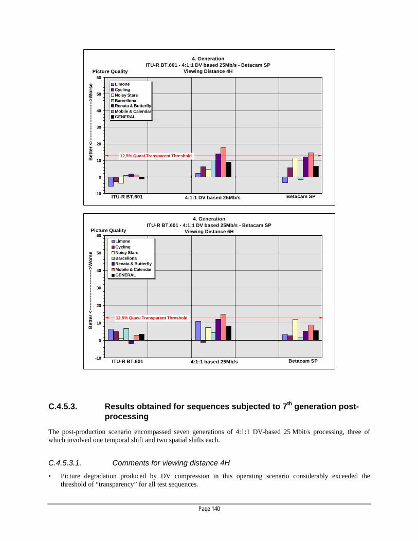
Page 140
4. GenerationITU-R BT.601 - 4:1:1 DV based 25Mb/s - Betacam SP
Viewing Distance 4H
-10
0
10
20
30
40
50
60
LimoneCyclingNoisy StarsBarcellonaRenata & ButterflyMobile & CalendarGENERAL
ITU-R BT.601 4:1:1 DV based 25Mb/s Betacam SP
12,5% Quasi Transparent Threshold
Picture Quality
Bet
ter
<---
----
----
----
----
----
-->W
ors
e
4. GenerationITU-R BT.601 - 4:1:1 DV based 25Mb/s - Betacam SP
Viewing Distance 6H
-10
0
10
20
30
40
50
60LimoneCyclingNoisy StarsBarcellonaRenata & ButterflyMobile & CalendarGENERAL
12,5% Quasi Transparent Threshold
ITU-R BT.601 4:1:1 based 25Mb/s Betacam SP
Picture Quality
Bet
ter
<---
----
----
----
----
----
-->W
ors
e
C.4.5.3. Results obtained for sequences subjected to 7th generation post-processing
The post-production scenario encompassed seven generations of 4:1:1 DV-based 25 Mbit/s processing, three ofwhich involved one temporal shift and two spatial shifts each.
C.4.5.3.1. Comments for viewing distance 4H
• Picture degradation produced by DV compression in this operating scenario considerably exceeded thethreshold of “transparency” for all test sequences.

Page 141
• For the critical test sequences “Mobile & Calendar”, the limit was exceeded significantly.
7. GenerationITU-R BT.601 - 4:1:1 DV based 25Mb/s - Betacam SP
Viewing Distance 4H
-10
0
10
20
30
40
50
60LimoneCyclingNoisy StarsBarcellonaRenata & ButterflyMobile & CalendarGENERAL
ITU-R BT.601 4:1:1 DV based 25Mb/s Betacam SP
Picture Quality
Bet
ter
<---
----
----
----
----
----
-->W
ors
e
12,5% Quasi Transparent Threshold
-10
0
10
20
30
40
50
60LimoneCyclingNoisy StarsBarcellonaRenata & ButterflyMobile & CalendarGENERAL
12,5% Quasi Transparent Threshold
7. GenerationITU-R BT.601 - 4:1:1 DV based 25 Mb/s - Betacam SP
Viewing Distance 6H
ITU-R BT.601 4:1:1 DV based 25 Mb/s Betacam SP
Picture Quality
Bet
ter
<---
----
----
----
----
----
-->W
ors
e
• On average, for both normal and critical pictures, the footprints created by DV compression were rated farbelow the degradation generated by Betacam SP.
• Although the threshold of visibility was exceeded in all cases, the acceptance level of picture quality achievedwithin this DV post-production scenario will depend on the individual broadcaster’s attitude on the acceptanceof Betacam SP picture quality in an identical operating scenario.
C.4.5.3.2. Comments for viewing distance 6H
• The absolute ratings are lower than in the 4H case shown above.
• In all but one case, the ratings for DVCPRO exceeded the transparency limit.

Page 142
• Analog Betacam was rated markedly worse than DVCPRO in practically all cases.
C.4.6. Picture quality of a 4:2:2 DV-based 50 Mbit/s compressionscheme
The proposed operating scenario is that of networked mainstream broadcast operations. To assess the picturequality and post-processing ceiling obtainable with 4:2:2 DV-based 50 Mbit/s compression, Digital Betacam wasincluded in the test as an established high-end compression system.
The results given below were obtained for viewing distances at 4H (34 observers) and 6H (26 observers) from asubjective test carried out by the RAI and the IRT on a 4:2:2 DV-based 50 Mbit/s compression scheme.
C.4.6.1. Results obtained for sequences subjected to 7th generation post-processing and pixel shift
The picture sequences were subjected to 7th generation post-processing with the pixel shift characteristics given inthe table below.
Processing Horizontal Shift (Pixel)
+1 = 2 Y pixel shift right ||-1 = 2 Y pixel shift left Vertical Shift (Line)
+1 = 1 line shift down || -1 = 1 line shiftup
1st generation → 2nd generation. no shift +1
2nd generation → 3rd generation. no shift +1
3rd generation → 4th. generation. no shift +1
4th generation → 5th generation. +1 no shift
5th generation → 6th generation. no shift -1 6th generation → 7th generation. -1 -2
Note: The “Diva with Noise” sequence was originally included in the test. This sequence is an extreme test for all compressionsystems. The “General” result, expressed as numerical values on the histograms above, represents the average over thesequences tested without inclusion of the “Diva with Noise” test sequence.
C.4.6.1.1. Multi-generation performance of Digital-S (DV-based 50 Mbit/s) compression
• At normal viewing distance, the picture quality of 1st generation Digital-S compression was practicallyindistinguishable from the 4:2:2 source.
• At normal viewing distance, experts had difficulty in identifying differences between the performance ofDigital-S compression through all generations for non-critical sequences. No remarkable decrease of picturequality was observed up to the 7th generation.
• In direct comparison with the source, critical sequences processed by Digital-S compression showed a certainsoftening of sub-areas containing high picture detail. This effect could be observed with a slight increasethrough each generation. In general, the level of impairment of seventh generation does not compromise thepicture quality.
C.4.6.1.2. Multi-generation performance of Digital-S (DV-based 50 Mbit/s) compressionand the compression used in Digital Betacam
• At normal viewing distance and for moderately critical sequences, experts had difficulty to identify differencesbetween the performance of the algorithms of the two digital compression systems.

Page 143
• For the first generation, the performance of Digital-S compression and the compression used in DigitalBetacam was rated to be identical.
7. GenerationITU-R BT.601 - Digital Betacam - 4:2:2 DV based 50 Mb/s - Betacam SP
Viewing Distance 4H
-10
0
10
20
30
40
50
60
NDR Lady
Noisy Stars
BarcellonaRenata&Butterflies
Mobile&Calendar
GENERAL
ITU-R BT.601 Betacam SP
12,5% Quasi Transparent Threshold
Picture QualityB
ette
r <-
----
----
----
----
----
----
>Wo
rse
Digital Betacam 4:2:2 DV based 50 Mb/s
7. GenerationITU-R BT.601 - Digital Betacam - 4:2:2 DV based 50 Mb/s - Betacam SP
Viewing Distance 6H
-10
0
10
20
30
40
50
60
NDR Lady
Noisy Stars
BarcellonaRenata&Butterflies
Mobile&Calendar
GENERAL
ITU-R BT.601 Betacam SP
12,5% Quasi Transparent Threshold
Picture Quality
Bet
ter
<---
----
----
----
----
----
-->W
ors
e
Digital Betacam 4:2:2 DV based 50 Mb/s
• At fourth generation, the performance of Digital-S compression and the compression used in Digital Betacamin the multi-generation scenario is similar. The picture quality of non-critical sequences is practicallypreserved by both systems. Differences between system performance are detectable on closer scrutiny and canbe described as „softness in areas of high picture detail” for Digital-S compression and “increased codingnoise” for compression used in Digital Betacam.
• At seventh generation, the different behavior of the two compression algorithms becomes more apparent. Theeffects described for the fourth generation performance are slightly accentuated. For moderately criticalsequences, the level of impairment was very low and did not compromise the overall picture quality. On directcomparison, picture quality provided by Digital Betacam compression was considered to be slightly better than

Page 144
that achieved with Digital-S compression. This is mainly due to the different subjective effects of “softness”and “coding noise” on perceived picture quality.
C.4.7. Digital interfaces
The table below indicates the type of interface required for a DV-based compression family and the respective statusof the specification.
Interface: Status
Defined In progress Not defined Standard Document
SDTI ü SMPTE 305 M
ATM ü FC ü
IEEE-1394 ü T-3 ü
OC-3 ü Satellite ü
C.4.8. Intra-family agile decoders
C.4.8.1. Market prospects
Panasonic and JVC have stated their commitment to produce an agile decoder chip which performs 4:2:0 / 4:1.1DV-based 25 Mbit/s and 4:2:2 DV-based 50 Mbit/s decoding. Both companies have further stated that the agiledecoder will also decode DVCAM bitstreams.
C.4.8.2. Decoding of different DV bitstreams with identical decoding delayat the output
The general feasibility of seamless switching between DV-based 25 Mbit/s and DV-based 50 Mbit/s bit inputstreams at SDI output level has been demonstrated.
The agile DV decoder will comply with requirement A in Section C.3.4.
C.4.8.3. Intra-family switching between different DV bitstreams at the input
The agile DV decoder will comply with requirement B in Section C.3.4.
C.4.8.4. Intra-family decoding between different DV packets within a singlebitstream
The agile DV decoder will comply with requirement C in Section B.3.4.

Page 145
C.4.9. Native decoders
DV decoders are native by definition.
C.4.10. Family relations
C.4.10.1. Tools available for intra-family transcoding
No special tools are currently available. All DV-based compression schemes feature the same basic compressionand macroblock structure. However, different sampling structure and horizontal / vertical pre-filtering requirestranscoding via baseband decoding.
C.4.10.2. Compatible intra-family record / replay
Input DV DVCAM DVCPRO@25 DVCPRO@50 Digital-S
Tape Cassette REC PLAY REC PLAY REC PLAY REC PLAY REC PLAY
DV Small Y Y Y Y N Y(*) N Y(*, **) N N
DV Large Y Y Y Y N Y N Y(*) N N
DVCAM Small N Y Y Y N Y(*) N Y(*, **) N N DVCAM Large N Y Y Y N Y N Y(**) N N DVCPRO@25
Medium N N N N Y Y Y Y N N
DVCPRO@25Large
N N N N Y Y Y Y N N
DVCPRO@50Medium
N N N N N N Y Y N N
DVCPRO@50Large
N N N N N N Y Y N N
Digital-S N N N N N N N N Y Y
Y = yes, N= no (*): With adapter
(**): Presently-available equipment does not support this functionality. Equipment under development will support playback of DVand DVCAM formats.
C.4.11. Editing flexibility and complexity• No Edit restrictions because of frame bound prediction window. Editing granularity is 1 frame.
• No special host / client interactions required. Assemble and insert edit at bitstream level is possible.
• Edit control via RS 422 or RS 232 protocol.

Page 146
C.4.12. Examples of some commercial format implementations
C.4.12.1. 4:1:1 DV-based 25 Mbit/s tape recording format ("DVCPRO")
Tape: 6.35 mm Metal Particle, 8.8m
Cassettes: Medium (up to 63 min.), Large (up to 125 min)
Robustness: Good, adequate for News & Sports (Note 1)
Slow-Motion and Shuttle: Limited, requires adaptation to picture build-up (Note 2)
DV replay: Yes (Note 3)
Audio channels: 2 channels, 48 kHz, 16 bit (Note 4)
Audio 1 / 2 cross-fade: 5 frames (Note 5)
Editing granularity on tape: 1 frame
Transparency of VBI: Transparent, limited to ca. 553 kbit/s, (Note 6)
SDTI Interface: Availability pending (Note7)
Note 1: The error rates measured under realistic stress conditions during the EBU test have confirmed that DVCPRO 25 Mbit/s is
adequately robust within the application field envisaged for the recording format. The error rates measured off-tape with errorcorrection completely switched off were in the range of 10-5 and 10-6, thus indicating a solid design of the complete head-to-tape area.
Note 2: For Slow-Motion, the replay quality is heavily dependent on the chosen setting. The identification of short audio and videoinserts during Shuttle is heavily dependent on the individual setting of the shuttle speed. Identification is further influenced byContent and length of the segment to be located. Details can be found in the EBU Test Report.
Note 3: This requires the use of an adapter cassette. Replay of DV and DVCAM recordings in the original DV format is possible withoutquality loss.
Note 4: One out of 65536 codes is reserved for error signaling. Code 8000h becomes 8001h.
Note 5: This operational mode seems to be uniquely confined to Europe. The 5-frame delay measured with current implementations isnot acceptable and will be remedied, according to Panasonic, by an optional, external RAM delay.
Note 6: Access is currently not implemented. Data located within this area will be recorded transparently. No cross influence betweenVBI data and active picture.
Note 7: The SDTI interface for the transport of audio, compressed video and Metadata in real-time and non-real-time has recentlypassed the final ballot with the SMPTE (SMPTE 305 M); practical implementation into digital equipment is planned for 4Q/98.
C.4.12.2. 4:2:2 DV-based 50 Mbit/s tape recording format ("DVCPRO50")
Tape: 6.35mm Metal Particle, (61 min,8.8m; 92min, 6,5m)
Cassettes: Medium (up to 31 min.), Large (up to 92 min)
Robustness: Good, adequate for Mainstream Broadcast Applications (Note 1)
Slow-Motion and Shuttle: Significant improvement in shuttle performance compared toDVCPRO (Note 2)
DV replay: Not tested, will be implemented in a specific model only
Audio channels 4 channels, 48 kHz, 16 bit (Note 3)
Audio 1 / 2 cross fade: 6 frames (Note 4)
Editing granularity on tape: 1 frame
Transparency of VBI: Transparency limited to 2 uncompressed lines / frame, (Note 5)
SDTI Interface: Availability pending (Note6)
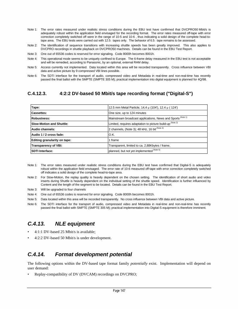
Page 147
Note 1: The error rates measured under realistic stress conditions during the EBU test have confirmed that DVCPRO50 Mbit/s isadequately robust within the application field envisaged for the recording format. The error rates measured off-tape with errorcorrection completely switched off were in the range of 10-5 and 10-6 , thus indicating a solid design of the complete head-to-tape area. The EBU tests were carried out with 12.5m tapes only. The behavior of 6.5m tape remains to be assessed.
Note 2: The identification of sequence transitions with increasing shuttle speeds has been greatly improved. This also applies toDVCPRO recordings in shuttle playback on DVCPRO50 machines. Details can be found in the EBU Test Report.
Note 3: One out of 65536 codes is reserved for error signaling. Code 8000h becomes 8001h.
Note 4: This operational mode seems to be uniquely confined to Europe. The 6-frame delay measured in the EBU test is not acceptableand will be remedied, according to Panasonic, by an optional, external RAM delay.
Note 5: Access currently not implemented. Data located within this area will be recorded transparently. Cross influence between VBIdata and active picture by 9 compressed VBI lines possible.
Note 6: The SDTI interface for the transport of audio, compressed video and Metadata in real-time and non-real-time has recentlypassed the final ballot with the SMPTE (SMPTE 305 M); practical implementation into digital equipment is planned for 4Q/98.
C.4.12.3. 4:2:2 DV-based 50 Mbit/s tape recording format ("Digital-S")
Tape: 12.5 mm Metal Particle, 14,4 µ (104'), 12.4 µ ( 124')
Cassettes: One size, up to 124 minutes
Robustness: Mainstream broadcast applications, News and Sports (Note 1)
Slow-Motion and Shuttle: Limited, requires adaptation to picture build-up (Note 2)
Audio channels: 2 channels, (Note 3); 48 kHz, 16 bit (Note 4)
Audio 1 / 2 cross fade: O.K.
Editing granularity on tape: 1 frame
Transparency of VBI: Transparent, limited to ca. 2,88Kbytes / frame,
SDTI Interface: planned, but not yet implemented (Note 6)
Note 1: The error rates measured under realistic stress conditions during the EBU test have confirmed that Digital-S is adequately
robust within the application field envisaged. The error rate of 10-6 measured off-tape with error correction completely switchedoff indicates a solid design of the complete head-to-tape area.
Note 2: For Slow-Motion, the replay quality is heavily dependent on the chosen setting. The identification of short audio and videoinserts during Shuttle is heavily dependent on the individual setting of the shuttle speed. Identification is further influenced byContent and the length of the segment to be located. Details can be found in the EBU Test Report.
Note 3: Will be upgraded to four channels
Note 4: One out of 65536 codes is reserved for error signaling. Code 8000h becomes 8001h.
Note 5: Data located within this area will be recorded transparently. No cross influence between VBI data and active picture.
Note 6: The SDTI interface for the transport of audio, compressed video and Metadata in real-time and non-real-time has recentlypassed the final ballot with SMPTE (SMPTE 305 M); practical implementation into Digital-S equipment is therefore imminent.
C.4.13. NLE equipment• 4:1:1 DV-based 25 Mbit/s is available;
• 4:2:2 DV-based 50 Mbit/s is under development.
C.4.14. Format development potential
The following options within the DV-based tape format family potentially exist. Implementation will depend onuser demand:
• Replay-compatibility of DV (DVCAM) recordings on DVCPRO;

Page 148
• Replay-compatibility of DVCPRO recordings on DVCPRO50;
• An integrated decoder for three DV-based tape formats (DVCPRO, DVCPRO50 and Digital-S) has beendemonstrated;
• Optional recording of DVCPRO signals on a DVCPRO50 recorder;
• 1/4 reduction of transfer time from tape / tape and tape / Hard Disk / tape with DVCPRO and DVCPRO50;
• Integration of DV-based tape-format supports into workstations for direct PC-based post-processing;
• Two times real-time digital audio and compressed digital video transfer using SDTI interface (SMPTE 305 M)for Digital-S.
C.4.15. Test equipment
Will be available.
C.5. Television production based onMPEG-2 4:2:2P@ML compression
C.5.1. Format stability
C.5.1.1. MPEG-2 4:2:2P@ML compression chip-sets
Chip-sets: Available
Source 1: IBM
Operating range: Up to about 50 Mbit/s
Cost: Oriented towards professional market
Application base: Telecom, computer and professional
Source 2: C-Cube DVX
Operating range: Up to 50 Mbit/s, GoP: I, IB, others
Cost: Oriented towards consumer & professional market
Application base: Telecom, computer, consumer, and professional (Note 1)
Source 3: Sony(Notes 2, 3)
Operating range: 15-50 Mbit/s, GoP: I, IB
Cost: Oriented towards professional market
Application base: Telecom, computer and professional
Source 4: Fast
Operating range: 50 Mbit/s and higher
Cost: Oriented towards professional market
Application base: Intra-frame only. Telecom, computer and professional
Standard: MPEG-2 4:2:2P@ML standardized by MPEG group.Transport protocols submitted to SMPTE for standardization (Note 4)
Note 1: Chip-sets are available for both professional and consumer applications

Page 149
Note 2: Sony has publicly stated its commitment to make the SX chip-set available together with the appertaining softwaredocumentation to all interested parties on an equitable and non-discriminatory basis. For reasons of optimum VTR stunt-modeoperation, the arrangement of coefficients within macroblocks within the Betacam SX native data stream differs from that of anMPEG-compliant data stream.
Note 3: Sony has announced its intention to produce “data re-ordering” chips which transparently translate the Betacam SX native datastream to a fully MPEG-compliant data stream (and vice versa). These chips will be made available to all interested parties onan equitable and non-discriminatory basis.
Note 4: MPEG compression allows great flexibility in encoder design. The balance of the great number of encoding parameters toachieve optimum quality is a manufacturer’s choice and need not be documented. Since most pre-processing, such as filteringor noise reduction, is not always required, the pre-processing parameters may be selected depending upon the nature of theimages and the capabilities of the compression system. These choices can be pre-set or can be adaptive. The multi-generationperformance of individual codec designs with identical data-rate and GoP structure but from different manufacturers and withdifferent pre-settings will therefore be difficult to predict and will require subjective testing in each case.
C.5.2. MPEG-2 4:2:2P@ML - an estimate of first-generationperformance
The diagram below shows the data-rates required to encode picture sequences of different coding complexity.Software codecs were used and data-rates were adjusted to achieve equal output performance in terms of noisepower of the differences between the original and the compressed / decompressed picture sequence (PSNR =40 dB).The prediction window could be adjusted and varied between GoPs in the range of 1 to 15 (Notes 1, 2, 3).
Note 1: The curves shown in the diagram should be taken as an indication of first-generation performance within the wide span of
MPEG-2 encoding options only. Taking signal differences as a measure of picture quality only allows coarse evaluation ofactual quality performance. The variance of encoding parameters allowed in MPEG-2 encoding structures to achieve thedesired flexibility will require subjective testing of each individual encoder design to determine the actual quality performance at agiven data-rate and GoP structure. The arrows indicate possible members of the MPEG-2 4:2:2P@ML compression familyenvisaged for Mainstream Broadcasting, News and Sports and for Contribution, as implemented in current industrial designs.
Note 2: Sony has demonstrated an MPEG-2 4:2:2P@ML at 50 Mbit/s (Intra-frame) implementation to the EBU. A formal subjectivetest of the picture quality obtained with the parameter settings chosen has been carried out by the EBU.
Note 3: The EBU has evaluated the performance of MPEG-2 4:2:2P@ML at 21 Mbit/s operation as selected for the EBU contributionnetwork. Results of a subjective test will be incorporated in the document at the time of IBC 98.
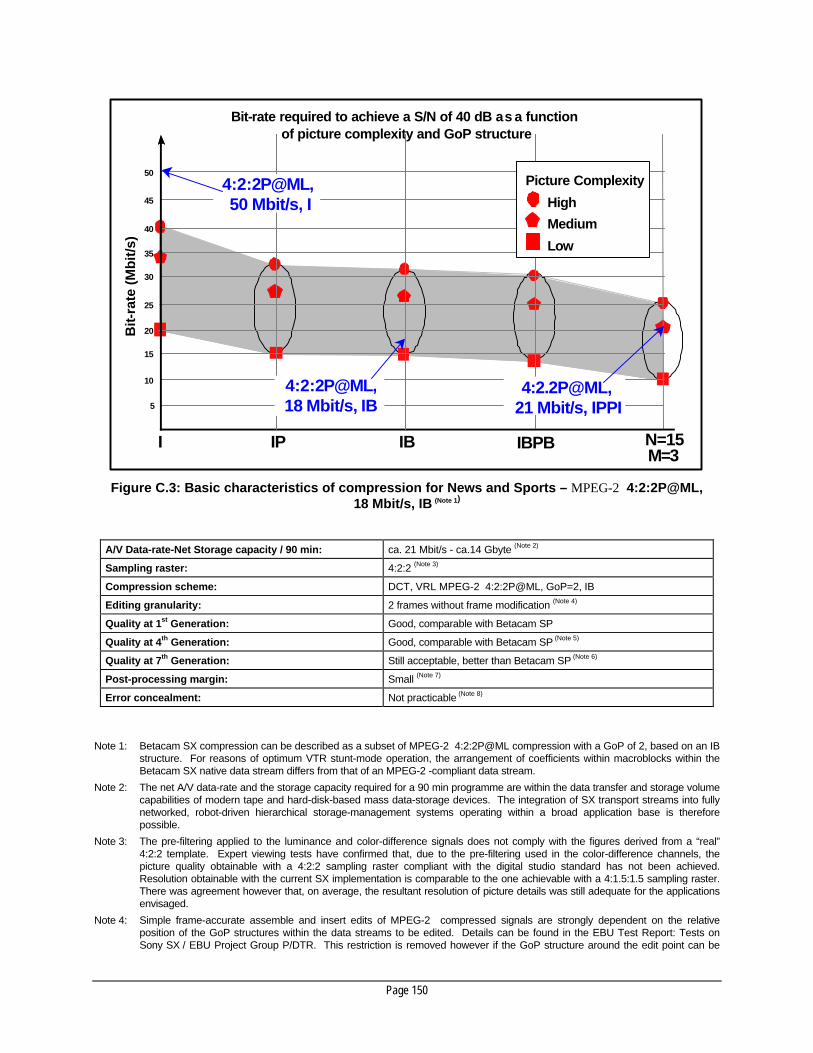
Page 150
Bit-
rate
(M
bit
/s)
35
Bit-rate required to achieve a S/N of 40 dB as a function of picture complexity and GoP structure
I IP IB IBPB N=15 M=3
50
45
40
30
25
20
15
10
5
4:2:2P@ML, 18 Mbit/s, IB
4:2.2P@ML, 21 Mbit/s, IPPI
4:2:2P@ML, 50 Mbit/s, I
Picture Complexity
High
Medium
Low
Figure C.3: Basic characteristics of compression for News and Sports – MPEG-2 4:2:2P@ML,18 Mbit/s, IB (Note 1)
A/V Data-rate-Net Storage capacity / 90 min: ca. 21 Mbit/s - ca.14 Gbyte (Note 2)
Sampling raster: 4:2:2 (Note 3)
Compression scheme: DCT, VRL MPEG-2 4:2:2P@ML, GoP=2, IB
Editing granularity: 2 frames without frame modification (Note 4)
Quality at 1st Generation: Good, comparable with Betacam SP
Quality at 4th Generation: Good, comparable with Betacam SP (Note 5)
Quality at 7th Generation: Still acceptable, better than Betacam SP (Note 6)
Post-processing margin: Small (Note 7)
Error concealment: Not practicable (Note 8)
Note 1: Betacam SX compression can be described as a subset of MPEG-2 4:2:2P@ML compression with a GoP of 2, based on an IB
structure. For reasons of optimum VTR stunt-mode operation, the arrangement of coefficients within macroblocks within theBetacam SX native data stream differs from that of an MPEG-2 -compliant data stream.
Note 2: The net A/V data-rate and the storage capacity required for a 90 min programme are within the data transfer and storage volumecapabilities of modern tape and hard-disk-based mass data-storage devices. The integration of SX transport streams into fullynetworked, robot-driven hierarchical storage-management systems operating within a broad application base is thereforepossible.
Note 3: The pre-filtering applied to the luminance and color-difference signals does not comply with the figures derived from a “real”4:2:2 template. Expert viewing tests have confirmed that, due to the pre-filtering used in the color-difference channels, thepicture quality obtainable with a 4:2:2 sampling raster compliant with the digital studio standard has not been achieved.Resolution obtainable with the current SX implementation is comparable to the one achievable with a 4:1.5:1.5 sampling raster.There was agreement however that, on average, the resultant resolution of picture details was still adequate for the applicationsenvisaged.
Note 4: Simple frame-accurate assemble and insert edits of MPEG-2 compressed signals are strongly dependent on the relativeposition of the GoP structures within the data streams to be edited. Details can be found in the EBU Test Report: Tests onSony SX / EBU Project Group P/DTR. This restriction is removed however if the GoP structure around the edit point can be

Page 151
changed. For edits requiring access to individual pixel elements (wipes, re-sizing, amplitude adjustments), the signals have tobe decoded.
Note 5: The limits of the SX compression scheme become conspicuous once more-elaborate post-processing of sequences originatingfrom ENG and Sports is required. Average picture quality has been rated to be still acceptable, but no longer good. Picturequality is still better than that obtained from Betacam SP under identical circumstances. In the case of Betacam SP, increasingnumber of generations beyond about 5 to 6 cause increasingly conspicuous spatial displacement of contiguous luminance andcolor-difference samples.
Note 6: For the application envisaged, despite the artifacts of the SX compression scheme accumulated in progressive generations,post-production headroom for processes requiring access to individual pixels is still considered adequate.
Note 7: Post-production potential outside the recommended applications for SX compression is limited, due to the combined effects ofreduced chroma-signal bandwidth and the progressive accumulation of compression artifacts.
Note 8: Because of the wide temporal prediction window, error concealment is not practicable and will lead to error propagation.Therefore sufficient margin must be allocated to the error-correction scheme and the format robustness to compensate for this.
C.5.3. MPEG-2 4:2:2P@ML, 50 Mbit/s, I, CBR -basic characteristics for mainstream broadcast production
A/V Data-rate-Net Storage capacity / 90 min ca. 53 Mbit/s - ca. 36 Gbyte: (Note 1)
Sampling raster: 4:2:2 (Note 2)
Compression scheme: DCT, VRL MPEG-2 4:2:2P@ML, 50 Mbit/s, GoP=1
Editing granularity: One TV-frame
Quality 1st Generation: Identical to Digital Betacam
Quality 4th Generation: Similar to Digital Betacam
Quality 7th Generation: Comparable, slightly worse than Digital Betacam
Post-processing margin: Adequate
Error concealment: Acceptable
Note 1: The net A/V data-rate and the storage capacity required for a 90 min programme are within the data transfer and storage volume
capabilities of modern tape- and hard-disk-based mass data-storage devices. The integration of a 50 Mbit/s transport streamsinto fully networked, robot-driven hierarchical storage-management systems, operating within a broad application base, istherefore possible.
Note 2: No pre-filtering of luminance and color-difference inputs was applied.
C.5.4. MPEG-2 4:2:2P@ML - subjective test results when followingITU-R Recommendation BT.500-7
The picture quality of MPEG-2 4:2:2P@ML compression schemes operating at different data-rates and GoPstructures have been evaluated subjectively and objectively within a variety of different operating scenarios.
The sequences below have been presented in the test in 4:2:2 quality (absolute reference) and in Betacam SP (Note)
quality (relative reference).
Note Different Betacam SP recorders were used for the MPEG-2 4:2:2P@ML, 18 Mbit/s, IB and MPEG-2 4:2:2P@ML, 50 Mbit/s, I-only tests. In both cases, the recorders were in current post-production use and were not specially selected or realigned. The

Page 152
histograms for the 7th generation performance in both test series clearly show the variance of test results achieved with analogequipment.
The subjective tests were performed in accordance with the rules given in ITU-R BT 500-7 for the application ofthe “Double Stimulus Continuous Quality Scale, (DSCQS)” method which entails two different viewing distances:four times picture height (4H) for the critical viewing distance and six times picture height (6H) for the normalviewing distance. The range of quality ratings extends from bad - poor - fair - good - excellent within a linearscale. The difference between perceived quality of the reference and the system under test is subsequently evaluatedand presented on a scale ranging from 0 to 100%.
The 12.5% border is defined as the Quasi Transparent Threshold (QTT) of visibility. The processed subjectivequality results do not scale linearly. In pictures rated 30%, degradation is quite visible.
C.5.5. MPEG-2 4:2:2P@ML, 18 Mbit/s, IB - picture quality issues
The proposed operating scenario ranges from acquisition only, to hard news and magazine production. The pictureContent of the sequences represent actions that are frequently encountered in both News and Sport.
C.5.5.1. Results obtained for sequences subjected to 1st generation post-processing
C.5.5.1.1. Comments for viewing distance 4H
• The average picture-quality ratings were dependent on picture Content and source quality. Even for the mostdemanding source picture, “Mobile and Calendar”, the rating for picture-quality degradation was noticeablybelow the “transparency” limit of 12.5%.
• In general, the average picture-quality degradation for the MPEG-2 4:2:2P@ML, 18 Mbit/s, IB compressionwithin the range of pictures under test was well below the 12.5% mark as the defined limit for visibility.
• In general, picture-quality degradation caused by the MPEG-2 4:2:2P@ML, 18 Mbit/s, IB compressionalgorithm were more visible than those of Betacam SP. These differences are within the range of the standarddeviation and are therefore statistically insignificant.
C.5.5.1.2. Comments for viewing distance 6H
• The same tendency was found in the voting here as for the 4H case given above, but was less pronounced dueto the reduced eye sensitivity at a viewing distance of 6H.
• In general, the average picture-quality degradation for Betacam SX within the range of pictures under test waswell below the 12.5% mark as the defined limit for visibility.

Page 153
1. GenerationITU-R BT.601 - 422P@ML,18Mb/s ("SX") - Betacam SP
Viewing Distance 4H
-10
0
10
20
30
40
50
60
LimoneCyclingNoisy StarsBarcellonaRenata & ButterflyMobile & CalendarGENERAL
ITU-R Betacam SP
12,5% Quasi Transparent Threshold
Picture Quality
Bet
ter
<---
----
----
----
----
----
-->W
ors
e
422P@ML,18Mb/s ("SX")
1. GenerationITU-R BT.601 - 422P@ML,18Mb/s ("SX") - Betacam SP
Viewing Distance 6H
-10
0
10
20
30
40
50
60
LimoneCyclingNoisy StarsBarcellonaRenata & ButterflyMobile & CalendarGENERAL
ITU-R BT.601
422P@ML,18Mb/s ("SX") Betacam SP
12,5% Quasi Transparent Threshold
Picture Quality
Bet
ter
<---
----
----
----
----
----
-->W
ors
e
C.5.5.2. Results obtained for sequences subjected to 4th generationprocessing
The post-production scenario encompassed four generations of MPEG-2 4:2:2P@ML, 18 Mbit/s, IB processing,two of which involved one temporal shift and one spatial shift each.
C.5.5.2.1. Comments for viewing distance 4H
• In general, the average picture-quality degradation for the range of pictures under test was still below the12.5% mark as the defined limit for “transparency” for both MPEG-2 4:2:2P@ML, 18 Mbit/s, IB compressionand Betacam SP.

Page 154
• For natural scenes, differences in quality shown in the histogram between Betacam SP and MPEG-2 4:2:2P@ML, 18 Mbit/s, IB compression are statistically insignificant.
• Only for critical test scenes “Renata-Butterfly” and “Mobile and Calendar”, MPEG-2 4:2:2P@ML, 18 Mbit/s,IB compression clearly exceeded that limit and the picture quality of Betacam SP was judged better than that ofMPEG-2 4:2:2P@ML, 18 Mbit/s, IB compression.
4. GenerationITU-R BT.601 - 422P@ML,18Mb/s ("SX") - Betacam SP
Viewing Distance 4H
-10
0
10
20
30
40
50
60
LimoneCyclingNoisy StarsBarcellonaRenata & ButterflyMobile & CalendarGENERAL
ITU-R BT.601
Betacam SP
12,5% Quasi Transparent Threshold
Picture Quality
Bet
ter
<---
----
----
----
----
----
-->W
ors
e
422P@ML,18Mb/s ("SX")
4. GenerationITU-R BT.601 - 422P@ML,18 Mb/s ("SX") - Betacam SP
Viewing Distance 6H
-10
0
10
20
30
40
50
60
LimoneCyclingNoisy StarsBarcellonaRenata & ButterflyMobile & CalendarGENERAL
ITU-R BT.601 Betacam SP
12,5% Quasi Transparent Threshold
Picture Quality
Bet
ter
<---
----
----
----
----
----
-->W
ors
e
422P@ML,18Mb/s ("SX")
• The artifacts produced by MPEG-2 4:2:2P@ML, 18 Mbit/s, IB compression in the natural scenes of the testcycle remained below the threshold of visibility, even at the critical viewing distance.
C.5.5.2.2. Comments for viewing distance 6H
• The absolute ratings for both Betacam SX and Betacam SP are lower than in the 4H case. For natural pictures,differences shown in the histogram between Betacam SX and Betacam SP are statistically insignificant.
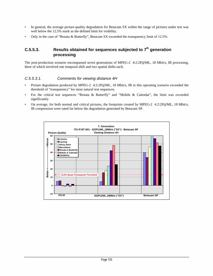
Page 155
• In general, the average picture-quality degradation for Betacam SX within the range of pictures under test waswell below the 12.5% mark as the defined limit for visibility.
• Only in the case of “Renata & Butterfly”, Betacam SX exceeded the transparency limit of 12.5%.
C.5.5.3. Results obtained for sequences subjected to 7th generationprocessing
The post-production scenario encompassed seven generations of MPEG-2 4:2:2P@ML, 18 Mbit/s, IB processing,three of which involved one temporal shift and two spatial shifts each.
C.5.5.3.1. Comments for viewing distance 4H
• Picture degradation produced by MPEG-2 4:2:2P@ML, 18 Mbit/s, IB in this operating scenario exceeded thethreshold of “transparency” for most natural test sequences.
• For the critical test sequences “Renata & Butterfly” and “Mobile & Calendar”, the limit was exceededsignificantly.
• On average, for both normal and critical pictures, the footprints created by MPEG-2 4:2:2P@ML, 18 Mbit/s,IB compression were rated far below the degradation generated by Betacam SP.
7. GenerationITU-R BT.601 - 422P@ML,18Mb/s ("SX") - Betacam SP
Viewing Distance 4H
-10
0
10
20
30
40
50
60
LimoneCyclingNoisy StarsBarcellonaRenata & ButterflyMobile & CalendarGENERAL
ITU-R BT.601
Betacam SP
12,5% Quasi Transparent Threshold
Picture Quality
Bet
ter
<---
----
----
----
----
----
-->W
ors
e
422P@ML,18Mb/s ("SX")

Page 156
7. GenerationITU-R BT.601 - 422P@ML,18Mb/s ("SX") - Betacam SP
Viewing Distance 6H
-10
0
10
20
30
40
50
60
LimoneCyclingNoisy StarsBarcellonaRenata & ButterflyMobile & CalendarGENERAL
ITU-R Betacam SP
12,5% Quasi Transparent Threshold
Picture Quality
Bet
ter
<---
----
----
----
----
----
-->W
ors
e
422P@ML,18Mb/s ("SX")
• Although the threshold of visibility was exceeded in all but one case, the acceptance level of picture qualityachieved within this MPEG-2 4:2:2P@ML, 18 Mbit/s, IB post-production scenario will depend on theindividual broadcaster’s attitude on the acceptance of Betacam SP picture quality in an identical operatingscenario.
C.5.5.3.2. Comments for viewing distance 6H
• The absolute ratings were lower than in the 4H case shown above.
• Analog Betacam SP was rated markedly worse than Betacam SX for all test pictures.
• For natural scenes, Betacam SX picture quality was rated to be transparent.
• For critical test pictures, Betacam SX exceeded the limit of transparency considerably.
• Even in the 6H case and for all test sequences, the ratings for Betacam SP exceeded the transparency limit.
• On average, picture quality of Betacam SX was at the limit of transparency.
C.5.6. MPEG-2 4:2:2P@ML, 50 Mbit/s, intra-frame - picture qualityissues
The histograms below show the results obtained for viewing distances at 4H (34 observers) and 6H (26 observers)from a subjective test carried out by the RAI and the IRT on a MPEG-2 4:2:2P@ML, 50 Mbit/s, intra-framecompression scheme.
Digital Betacam – as an established high-end compression system – was included in the test in order to assess thepicture quality and post-processing ceiling obtainable with non-pre-filtered MPEG-2 4:2:2P@ML, 50 Mbit/s, CBR,intra-frame compression (which is advocated as one option for use in networked mainstream broadcast operations).

Page 157
C.5.6.1. Results obtained for sequences subjected to 7th Generation post-processing with pixel shift
The picture sequences were subjected to 7th generation post-processing with the pixel shift characteristic given inthe table below:
Processing Horizontal Shift (Pixel)
+1 = 2 Y pixel shift right ||-1 = 2 Y pixel shift left Vertical Shift (Line)
+1 = 1 line shift down || -1 = 1 line shiftup
1st generation → 2nd generation. no shift +1
2nd generation → 3rd generation. no shift +1
3rd generation → 4th generation. no shift +1
4th generation → 5th generation. +1 no shift
5th generation → 6th generation. no shift -1 6th generation → 7th generation. -1 -2
Note: The “Diva with Noise” sequence was originally included in the test. This sequence is an extreme test for all compression
systems. The “General” result, expressed as numerical values on the histograms below, represents the average over thesequences tested without inclusion of the “Diva with Noise” test sequence.
C.5.6.1.1. Multi-generation performance of MPEG-2 4:2:2P@ML (50 Mbit/s, I-Frame)compression
• At the normal viewing distance, the picture quality of 1st generation MPEG-2 4:2:2P@ML compression waspractically indistinguishable from the 4:2:2 source.
7. GenerationITU-R BT.601 - Digital Betacam - 422P@ML, 50 Mb/s - Betacam SP
Viewing Distance 4H
-10
0
10
20
30
40
50
60
NDR Lady
Noisy Stars
BarcellonaRenata&Butterflies
Mobile&Calendar
GENERAL
ITU-R BT.601 422P@ML, 50 Mb/s Betacam SP
12,5% Quasi Transparent Threshold
Picture Quality
Bet
ter
<---
----
----
----
----
----
-->W
ors
e
Digital Betacam

Page 158
7. GenerationITU-R BT.601 - Digital Betacam - 422P@ML, 50 Mb/s - Betacam SP
Viewing Distance 6H
-10
0
10
20
30
40
50
60
NDR Lady
Noisy Stars
BarcellonaRenata&Butterflies
Mobile&Calendar
GENERAL
ITU-R BT.601 422P@ML, 50 Mb/s Betacam SP
12,5% Quasi Transparent Threshold
Picture Quality
Bet
ter
<---
----
----
----
----
----
-->W
ors
e
Digital Betacam
• At the normal viewing distance, experts had difficulty identifying differences between the performance ofMPEG-2 4:2:2P@ML compression through all generations for non-critical sequences. No significant decreaseof picture quality was observed up to the 7th generation.
• In direct comparison with the source, critical sequences processed by MPEG-2 4:2:2P@ML compressionshowed some coding noise and a certain loss of resolution in sub-areas containing high picture detail. Thiseffect could be observed with a slight increase through each generation. In general, the level of impairment ofthe 7th generation does not compromise the picture quality.
C.5.6.1.2. Multi-generation performance of MPEG-2 4:2:2P@ML (50 Mbit/s, I-Frame)compression vs. the compression used in Digital Betacam
• At normal viewing distance and for moderately critical sequences, experts had difficulty to identify differencesbetween the performance of the algorithms of the two digital compression systems.
• For the first generation, the performance of MPEG-2 4:2:2P@ML compression and the compression used inDigital Betacam was rated to be identical.
• At fourth generation, the performance of MPEG-2 4:2:2P@ML compression and the compression used inDigital Betacam in the multi-generation scenario is similar. The picture quality of non-critical sequences ispractically preserved by both systems. Differences between system performance are only detectable on closerscrutiny. Some loss of resolution and increased coding noise in areas of high picture details were detected forMPEG-2 4:2:2P@ML compression when compared with Digital Betacam.
• At seventh generation, the differences between the systems are marginal. The effects described for the fourthgeneration performance are slightly accentuated. For moderately-critical sequences, the level of impairmentwas very low and did not compromise the overall picture quality. On direct comparison, the picture qualityprovided by Digital Betacam compression was considered to be slightly better than that achieved with theMPEG-2 4:2:2P@ML compression. This is mainly due to some loss of resolution and a slightly increasedcoding noise with more critical sequences in the case of the MPEG-2 4:2:2P@ML compression.

Page 159
C.5.7. Digital interfaces
The table below indicates the type of interface required for a compression family based on MPEG-2 4:2:2P@ML,and shows the status of the various specifications.
Interface: Status
Defined In progress Not defined Standard Document
SDTI ü SMPTE 305 M
ATM ü AAL 5 / AAL 1
FC ü
IEEE-1394 ü
T-3 ü
OC-3 ü
Satellite ü
C.5.8. Agile decoders
Throughout the broadcast “programme chain”, a number of different MPEG profiles, levels and bit-rates may beused. These include MPEG-2 4:2:2P@ML for production and contribution, and MPEG-2 MP@ML fordistribution and transmission.
MPEG offers several methods for interoperation between bitstreams of different data-rates. Agile decoders workingautomatically over the 15 - 50 Mbit/s range of MPEG-2 4:2:2P@ML have been implemented and demonstrated byseveral manufacturers. Furthermore, these agile decoders may also have to operate at MPEG-2 [email protected] require that source material coded at different rates can be seamlessly edited, mixed and processedwithout additional intervention.
C.5.8.1. Decoding of different MPEG-2 4:2:2P@ML bitstreams with identicaldecoding delay at the output
The general feasibility of seamless switching between different MPEG-2 4:2:2P@ML encoded input streams atSDI output level has been publicly demonstrated.
The integrated agile MPEG-2 decoder chip will comply with requirement A in Section C.3.4.
C.5.8.2. Intra-family switching between different MPEG-2 4:2:2P@MLbitstreams at the input
The intra-family agile MPEG-2 decoder chip will comply with requirement B in Section C.3.4.
C.5.8.3. Intra-family decoding between different MPEG-2 4:2:2P@MLpackets within a single bitstream
The agile MPEG-2 decoder chip will comply with requirement C in Section C.3.4.
Page 160
C.5.9. Native Betacam SX bitstream decoders
The native Betacam SX bitstream does not comply with the specification of an MPEG-2 4:2:2P@ML TransportStream for reasons of optimum stunt-mode operation. A native decoder or a bitstream converter at 4x speed istherefore required (and will be made available) to process the Betacam SX bitstream. A formal specification of theBetacam SX native format has been prepared as a general reference document. This document is not a Standardbut a freely-available published specification.
C.5.10. Family relations
C.5.10.1. Tools available for MPEG-2 intra-family transcoding
The following options within both the MPEG-2 4:2:2P@ML and the MPEG-2 MP@ML formats exist:
a) Transcoding between MPEG bit-rates can be achieved by restricting the decoding processes to a minimum andby transferring information extracted by the decoding process to the re-encoder. Information such as theprevious quantization levels, motion vector information and GoP information can help the re-encoder moreaccurately reverse the decoding process at the new bit-rate. By utilizing techniques explored in the ACTSATLANTIC Project 19, flexible adjustment of data-rate to different post-production, storage, distribution andtransmission requirements by transcoding into different GoP structures can be achieved with reduced qualityloss. However, this applies only in the case where the picture Content is not changed between transcoding.
Complete transparency in cascading of identical encoding structures can be achieved if the relatively complexstep of re-using all the relevant information is taken.
Transparent cascading in conjunction with intermediate video or audio processing requires the routing ofhelper information through the processing chain, the maintenance of strict synchronism between macroblocksand helper data and the provision of dedicated I/O ports for encoders and decoders. Specifications ofautomatically routed and synchronized helper data (MOLE TM) for both the video and audio have beensubmitted to the SMPTE for standardization.
a) Sony will provide optimized transcoding between bit-rates to support the flexibility benefits of MPEG-2 . Thetranscoders will not necessarily be working on the same principles as the Atlantic project
C.5.11. Editing flexibility and complexity
At bit-rates in excess of 40 Mbit/s it is likely that I-frame-only structures will be implemented. In the case of lowerbit-rates and GoPs greater than 1, interoperability between equipment of different GoPs may require someadditional processing. Assemble-and-insert edits of extended MPEG-2 GoP structures require either decoding ofthe compressed data steam or a forced P-encoding of an original B picture, depending on the actual positioning ofthe GoP structure relative to the edit point. This requires a degree of interactivity between the devices involved inediting, e.g. pre-load of data if the edit segment is streamed off an HD server or a confidence replay head, in thecase of compressed data replay off and to tape.
19 The work of the “Atlantic” project, led by the BBC and Snell and Wilcox (and described in: Seamless Concatenation of MPEG-2
bitstreams - An introduction to MOLE TM Technology), is directed towards providing benefits such as:
§ transparent cascading;
§ bit-rate changing;
§ frame-accurate video switching, editing and full post-production;

Page 161
C.5.12. Examples of some commercial format implementations
C.5.12.1. 422P@ML, 18 Mbit/s, IB tape recording format ("Betacam SX“)
Tape: 12.65 mm Metal Particle, 14.5 µ
Cassettes: Small (up to 60 min); Large (up to 184 min)
Robustness: very good, adequate for in News & Sports (Notes 1, 2)
Slow-Motion and Shuttle: good off-tape, very good off HD (Note 3)
Betacam SP replay: O.K. (Note 4)
Audio channels: 4 channels, 48 kHz, 16 bit
Editing granularity on tape: Equipment dependent. 1 frame with pre-read heads possible (Note 5)
Cross fade-delay of Audio Ch1 / Ch2: O.K.
Transparency of VBI: 608 lines recorded , transparent for 1440 samples/field. (Note 6)
SDTI Interface: Already implemented (Note 7)
Extensibility to a format family: Inherent in MPEG
Note 1: Replay capability of Betacam SP tapes has been one of the key requirements in the development of the SX format. The use of½-inch MP tape, together with a moderate data-rate of 44 Mbit/s, allows generous dimensioning of all recording parameters andcontributes significantly to the excellent robustness of the whole system. This is confirmed by the error rates measured duringthe EBU Tests which document the excellent robustness under a variety of different and realistic stress conditions. The actualerror-rate performance of the SX Camcorder could not be measured however. The error rate of 10-6 measured off-tape with theHybrid-Recorder provides a testimony of the robust design of the head and tape area.
Note 2: Compressed video signals require elaborate error-correction schemes to guarantee data integrity through noise-infectedchannels. An overload of the Forward Error Correction system results in the loss of complete macroblocks. Concealment – asthe obvious panacea to cope with such situations (by substituting complete erroneous macroblocks by spatially adjacent ones) –will achieve only limited results. SX compression does not allow the substitution of erroneous macroblocks by spatiallycoincident macroblocks from the preceding frame. This would lead to significant error propagation due to the prediction rangeembracing several frames. The FEC used in SX, and the use of relaxed recording parameters possible with the available tapearea, compensate this however.
Note 3: The audio / video replay quality was good on all settings chosen for Slow-Motion and Shuttle replay. The identification of shortaudio and video inserts during shuttle is also strongly dependent on the setting of the shuttle speed. Identification is furtherinfluenced by scene Content and the length of the inserted segment to be located. Details can be found in the EBU TestReport.
Note 4: When replaying original Betacam SP recordings on SX, a reduction of the video signal / noise ratio of 3 dB was measured, whencompared to replay on Betacam SP. Betacam SP FM audio can be replayed from SX.
Note 5: Frame-accurate assemble-and-insert edits of MPEG-2 compressed signals is strongly dependent on the relative position of theGoP structures within the data streams to be edited. Details can be found in the EBU Test Report. For edits requiring accessto individual pixel elements (wipes, re-sizing, amplitude adjustments), the signals have to be decoded.
Note 6: With the exception of 1440 samples, input data in this area will not be conveyed transparently through the SX recording andreplay channel. Mutual influence of VBI data and data in the active picture area can therefore not be excluded. For details, seethe EBU Test Report. Cross-talk between data in the active video area and the VBI lines subjected to compression encodinghas been measured.
Note 7: The SDTI interface for the transport of the audio, compressed video and Metadata stream in real-time and non-real-time hasrecently passed the final ballot at the SMPTE; a practical implementation into SX equipment is therefore expected imminently.
C.5.13. NLE equipment
MPEG-2 4:2:2P@ML and MPEG-2 MP@ML NLE equipment is available.
§ better-than-frame-accurate audio switching and editing.

Page 162
C.5.14. Format development potential
MPEG-2 compression operates over a wide range of profiles, levels, GoPs and data-rates. This provides the userwith the flexibility to select the combination of picture quality, operational flexibility and economy which isrelevant to the specific application. A wide range of applications can be addressed within the toolbox provided byMPEG-2 , ranging from distribution at lower bit-rates using MPEG-2 MP@ML, to production and post-productionusing MPEG-2 4:2:2P@ML at higher data-rates, up to HDTV applications using MPEG-2 MP@HL and MPEG-2 4:2:2P@HL
.Note: Constant quality can be achieved if the application supports variable data-rate.
C.5.15. Test equipment
Available on the market.
C.6. Supplement A: EBU Statement D79-1996– Open standards for interfaces forcompressed television signals
EBU Committee: PMC. First Issued: November 1996.
The proposals to use compressed signals on a number of new television recording formats have raised a number ofquestions about interfaces.
There are a number of advantages in interconnecting equipment associated with these formats using interfaceswhich carry the compressed signals.
These advantages include:
• the avoidance of multiple coding and decoding;
• cost effective storage on disk and tape;
• the possibility of non-real-time transfer, particularly at faster than real-time.
However, to best exploit these advantages, broadcasters should be able to interconnect equipment from a variety ofmanufacturers.
Therefore, the EBU requires:
• that a single interface should be defined to carry compressed television signals;
• that all elements of the interface should be open and fully specified.
Page 163
C.7. Supplement B: EBU Statement D80-1996– Compression in television programmeproduction
EBU Committee: PMC. First Issued: November 1996.
At the present time, broadcasters are faced with a choice between incompatible compression algorithms used ondifferent non-linear editing and acquisition devices. Systems based on the new tape recording formats SX andDVCPRO operate on compression algorithms at 18 and 25 Mbit/s respectively and are intended to be used in theacquisition of Sports and News material. New tape recording formats for mainstream television applications havealready been announced. One is based on an extension of the DVCPRO compression algorithm to the 4:2:2 signalformat and will operate at about 50 Mbit/s. Other formats based on the 4:2:2profile@ML of MPEG may follow.
It is possible to integrate devices using compression systems into existing digital facilities if they are equipped withthe standard serial digital component interfaces in accordance with ITU-R Recommendation BT.656. However, thecompressed signals must first be decoded into ITU-R Recommendation BT.601 format.
The following consequences also arise:
• any further re-encoding and decoding of the previously compressed signal, such as may be required for furthernon-linear editing, will further increase the loss of signal quality;
• Even for simple assemble editing, programme segments encoded with different compression algorithms wouldeach need to be decoded into BT.601 format. Subsequently, a decision may have to be made on which formatis used for the edited programme material for future storage on a server or in the archive.
• The cost and operational benefits of an integrated tape and disk strategy using a single algorithm would benullified by the time required to transfer the programme material between different media. This is becausethere is little possibility of faster-than-real-time transfer between the acquisition, processing and storagedevices when using signals in ITU-R BT.601 form.
The provision of a single interface standard to carry compressed signals would alleviate this situation but theinterface signal formats based on existing algorithms would not be compatible with each other or with otherMPEG-based standards. Unfortunately, the EBU sees little likelihood of achieving harmonization at bit-rates in therange 18-25 Mbit/s.
The situation is different for compression algorithms operating at higher bit-rates, which may possibly be used inmainstream television studio operations. No significant amount of equipment is installed in this area of activityand hence the possibility still exists for achieving harmonization.
The EBU is encouraged by the continued improvements in performance and cost of disk storage and considers that:
• there are real economic benefits to be achieved through the use of a single compression algorithm and fileformat for programme exchange;
• intermediate storage and long term archival of material in a variety of formats is inefficient and createsproblems extending into the future;
• disk-based editing produces time and cost benefits over tape-based systems;
• there are technical and system benefits for programme production through an ability to select equipment fromdifferent suppliers as appropriate for different applications;
• that compression algorithms operating in an I-frame-only format at about 50 Mbit/s have been demonstratedand they are likely to offer a picture quality and a headroom for post-processing which are appropriate for allbut the most-demanding studio operations.

Page 164
The EBU firmly believes that:
• for high-end programme production, uncompressed signals according to ITU-R Recommendation BT.601 orsystems using lossless compression or systems using lossy DCT-based compression with a compression factornot exceeding 2 should be used;
• for mainstream programme production and for programme acquisition using low bit-rate compression formatswhere the operational advantages of compression are obvious, only a single, open compression algorithmshould be applied for storage or file transfer applications.
Furthermore, this system should be operating at 50 Mbit/s and use an I-frame-only format.

Page 165
Annex D: Wrappers and Metadata
D.1. First Request for Technology
D.1.1. Introduction
This section of the RFT covers the format of Metadata and the Wrappers used to transport or store this datatogether with any supported Content items. In general, these formats will be split into stream formats and fileformats. A file is defined here as analogous to a computer file and is normally dealt with as a unit, whereas astream is defined as a continuous flow of data with the capability for receivers to join at any time during astreaming operation (within some published limits). The purpose of these formats is to encourage the maximumpractical interoperability between diverse systems.
Background information to this RFT is to be found in Section 2 and Annex D of the EBU / SMPTE document“Joint Task Force for Harmonized Standards for the Transfer of Programme Material as Bitstreams, First Report:User Requirements” (April 1997).
D.1.2. Submission details
D.1.2.1. Description
A description of the offering is required, including available materials, supporting documentation and anycommercially-available implementations.
D.1.2.2. RFT table
The table on the next page should be completed with marks made to indicate the areas of compliance. This tablewill be used to categorize submissions and to check broad compliance with the objectives of the RFT.
Detailed information can be added by using separate pages. Reference to this additional information can be madeby indicating “note 1”, “note 2” etc. in the table.
The table headings are defined as follows:
• Offered indicates whether the response covers this aspect of the requirement;
• Defined indicates that the response covers a defined way of dealing with this aspect of the requirement;
• Universal indicates that the response covers this aspect for all application areas in its current form;
• Extensible indicates that the offering can be extended to cover this aspect of the requirement;
• Timeframe indicates the timeframe in which the response will meet this requirement.
D.1.2.3. Footnotes to the table
Please attach additional supporting information as needed (use “note: x” as a reference from the table to theadditional information).

Page 166
D.1.2.4. Supporting materials, APIs and protocol documents
Please attach any additional supporting material as separate documents.
Ref. * RFT Topic (note) Offered Defined Universal Extensible Time frame
1 Does the format support streaming (ref. 2.4)? 2 Does the format support interleaving (ref. 2.8)? 3 Does the format support file storage ref. (2.4)? 4 If 1 and 3are answered with a “Y”, are the file and stream formats
interoperable?
5 Does the system support a unique identifier (ref. 2.9)? 6 Is a registration procedure for Metadata types in place? 7 Can Essence types be added to the format (ref. 2.19)? 8 Can Metadata types be added? 9 Does the system have a flexible class hierarchy? 10 Are user-defined hierarchies supported? 11 Are different Metadata Sets (templates) supported? 12 Does the system support the Content structure described
in ref. 2.2.1.?
13 Does the system support multiple character sets i.e. Unicode,ISO extended language support?
14 Is a machine-readable plain text format supported? 15 Can files be partitioned into smaller files (ref. 2.6)? 16 Are multiple hardware / software operating platforms supported? 17 Are different byte orderings supported (ref. 2.7)? 18 Are multiple generations or versions of Metadata supported
(ref. 2.10)?
19 Can Metadata be referred to by pointer (indirection) (ref. 2.11)? 20 Are methods of systematic indexing supported (ref. 2.12)? 21 Are methods of specific indexing supported (ref. 2.12)? 22 Is derivation history supported (ref. 2.13)? 23 Are security features implemented (ref. 2.14)? 24 Is transaction logging supported within the format (ref. 2.15)? 25 Are property rights supported within the format (ref. 2.16)? 26 Is a material management system available for this format
(ref. 2.17)?
27 Is an API available to the format (ref. 2.18)? Note these references can be found in the First Report of the Task Force on User Requirements, April 1997.
D.2. Second Request for Technology
D.2.1. Introduction
In the analysis of responses to the first Request for Technology, it was realized that several of the responses offeredcomplete systems whose capabilities overlapped. Although reconciliation of these systems into a single systemmight be achieved, the resulting system would be of such wide scope that the process of standardization and

Page 167
implementation of the resulting standard would take a very long time. This does not meet the TFHS goal ofselecting a file format which can be standardized and deployed in the near future.
It was also clear that a common element of all responses was the use of a general-purpose persistent storagemechanism at a relatively low level of complexity. In all cases, the data model of the overall system was mappedonto such a storage subsystem.
Therefore, the Sub-Group determined to proceed with two tasks in parallel:
• to solicit specific solutions to the storage mechanism, and either choose a single solution or create anindependent public domain solution;
• to specify an overall data model, to which any commercial or pre-existing system could in principle be mappedeither directly or by the use of translation software.
This Second Request for Technology addresses the first of these tasks.
D.2.2. Licensing issues
Considering the importance of this element of technology, the TFHS is specifically requesting full documentation ofthe storage mechanism and conformance to the following guidelines:
To be standardized, any technologies must be open in three respects:
• existing implementations must be licensable;
• technologies must be documented sufficiently to permit new implementations from the ground up, without fees;
• a due-process standards body must have control of the specification in the future;
The TFHS will also recommend compliance testing by an external organization.
D.2.3. Evaluation of responses
Responses were evaluated during the meeting in Atlanta over the period March 5th~ 7 th, 1998.
If no single response met all requirements, the Sub-Group proposed to create a universal format in the publicdomain under the direction of a standards body, probably the SMPTE.
However, one of the responses addressed all the requirements. The documentation was studied and forwarded tothe SMPTE as the proposed universal standard.
D.2.4. Documentation requirements• A full description of the bitstream generated by the storage mechanism. The description must indicate through
diagrams and tables how each data construct appears in the functional requirements, when mapped onto asequence of bytes.
• An item-by-item response to each functional requirement listed below, as a simple Yes or No plus a singleparagraph of explanation.
• A statement on licensing issues, covering the points listed above, and listing any fees charged for the use ofexisting implementations, and indicating if any patents, trademarks or intellectual property rights exist and theproposal for freeing the technology from them.

Page 168
• Optionally, additional documentation may be provided in separate documents. This may include referencespecifications, or descriptions of additional features of the technology. However, this documentation must notbe required to be read in order to understand and evaluate the response.
D.2.5. Functional requirements• The storage mechanism shall provide a method to uniquely identify the file format within the file itself. The
identification shall be independent of the byte orderings of the file and of the platform. The identification isnecessary to distinguish the bitstream from any other bitstream. The identification data shall be an SMPTEAdministered Universal Label in accordance with SMPTE 298M-1997.
• The storage mechanism shall provide a method to define objects. The objects shall consist of a set ofproperties. Each property shall have a property name, property type name and property value.
• The storage mechanism shall not constrain the number of objects or properties within the file, and it shall notconstrain the number of properties in any object.
• The storage mechanism shall provide a method to define a property name. The storage mechanism shall allowa property name to be an SMPTE Administered Universal Label in accordance with SMPTE 298M-1997.
• The storage mechanism shall provide a method to define a property type name. The storage mechanism shallallow a property type name to be an SMPTE Administered Universal Label in accordance with SMPTE 298M-1997.
• The storage mechanism shall provide a method to read and write a property value. The storage mechanismshall allow a property value to be a sequence of bytes. The storage mechanism shall not restrict the value ofany byte in the sequence and shall not restrict the length of property values to a length less than 264-1 bytes.
• The storage mechanism shall provide a method to read and write a property value with a byte ordering thesame as or different from the default byte ordering in the file, without requiring that the file or the propertyvalue be reordered before or after the operation.
• The storage mechanism shall provide a method to read and write a property value with a byte ordering thesame as or different from the native byte ordering of the platform, without requiring that the file or the propertyvalue be reordered before or after the operation.
• The storage mechanism shall provide a method to access a header object, which can also be used as an index toaccess the objects in the file.
• The storage mechanism shall provide a method to access each object in a file, in any order or sequence.
• The storage mechanism shall provide a method to specify that a property value is a reference to an object in thesame file and shall provide a method to access an object in the file by using such a property value.
• The storage mechanism shall provide a method to access all of the properties of an object.
• The storage mechanism shall provide a method to access a property of an object by specifying the propertyname and the property type name.
• The storage mechanism shall provide the following methods to access a property:
– a method to get the property name of a property;
– a method to get the property type name of a property;
– a method to get the length of the property value in bytes;
– a method to determine if a property exists in an object;
– a method to add a property to an object by specifying the property name, the property type name andthe property value;
– a method to read or write the entire property value;
– a method to read or write a portion of the property value.
Page 169
• The storage mechanism shall allow an object to have a property with a property name that is the same as theproperty name of a property on a different object, and to have a property type name that is different from theproperty on the other object.
• The storage mechanism may optionally provide a method to control the relative placement of the various dataconstructs within the file.
D.3. Responses to the Requests for Technology The documents referenced below were accurate at the time of publication and represent a snapshot of that time.Many items below are subject to further development so the reader is encouraged to locate more recent documentswhere available. In many instances these documents will eventually be superseded by published standards. Thesedocuments are grouped into Storage, Streaming and Metadata responses. The sequence order is not significant.
D.3.1. Open Media Framework Interchange
The Open Media Framework Interchange (OMFI) Specification is a data model for representation of Essence andMetadata in Complex Content Packages. It is intended to be used in conjunction with a low-level storagemechanism for managing the actual storage of information in the file.
It is recommended that the OMFI data model is translated to use standardized SMPTE Labels and to operatetogether with an SMPTE-standardized low-level storage mechanism, and is then extended as new requirements forComplex Content Packages are documented. The proposers have committed to implement these changes and haveproduced a new specification called the Advanced Authoring Format (AAF).
A proposed standard to document the format is under consideration by SMPTE P18.27.
D.3.2. Structured Storage
The Microsoft Structured Storage file format has been submitted as a response to the EBU / SMPTE Joint TaskForce’s Metadata and Wrappers RFT for a low-level storage mechanism, and has been redrafted as a proposedstandard and submitted to SMPTE P18.27. It is also included within the specification of the Advanced AuthoringFormat (AAF).
Structured storage is a portable and scaleable interchange file format, designed to store a complex hierarchy ofEssence and Metadata, and can be viewed as a file system within a single file.
D.3.3. Advanced Streaming Format
Microsoft Advanced Streaming Format (ASF) is an extensible presentation file format (i.e. a “Wrapper") designedto store synchronized multimedia data. Although ASF can be edited, it is not an editing format per se, but rather isdesigned to work as an output streaming format, potentially created from the existing editing formats (such asOMFI or AVI / Wave). ASF was explicitly designed to address the media streaming needs of the Internetcommunity. It supports data delivery over a wide variety of networks and protocols while still proving to be wellsuited for local playback.
A proposed standard will de drafted and submitted to SMPTE P18 for consideration.

Page 170
D.3.4. QuickTime®
Apple Computer’s QuickTime® software includes a file format which serves as a Wrapper for multimedia Contentthroughout its lifecycle. The file format is supported by a large number of tools, primarily but not exclusivelythrough the cross-platform multimedia layer of the QuickTime® software from Apple Computer Inc. The fileformat was designed to be a flexible Wrapper for a wide variety of Content formats (e.g. Video, Audio, MIDI etc.),and multiplex formats (e.g. AVI, WAV etc.). The design of the format is adaptable to various streaming protocols,and for various stages in the Content lifecycle.
The design of the “Intermedia format” in the draft MPEG-4 Systems (ISO 14496-1) Version 2 is derived from theQuickTime® file format with additions and changes to accommodate the specific requirements of MPEG-4.
D.3.5. “Strawman” proposal for the structure of a Wrapper
A document was received with proposals for an Interchange Wrapper file which included a number of issuesdiscussed in the main part of this report. The topics discussed included a proposal for a UMID, a proposal for aProxy Wrapper interchange structure, a proposal for a Content Element and a list of suitable file structures for thebasis of interchange.
The sections on a Proxy Wrapper interchange structure and the structure of a Content Item element are available asthe basis of an SMPTE Standard in the P18 group. The other topics are already in progress.
D.3.6. SDTI Content package
A proposed format for the transmission of elementary streams over an SDTI (SMPTE 305M) connection has beensubmitted to the SMPTE for preparation as a standard using Content Packages formatted as a stream. SDTI offersa synchronous stream transfer carrier and this is applied in the proposal by providing specifications for picture-bounded Content Elements.
As of the publication date of this report (September 1998), this proposed standard is being balloted by the SMPTEPacketized Television Technology Committee.
D.3.7. Betacam SX® format over SDTI
A document has been made available detailing the format used by Betacam SX® for the transfer of coded bitstreamsas a Content Package over SDTI. This document is not standardized, but is freely available to all parties on requestto Sony.
D.3.8. MPEG-2 Transport Stream over SDTI
A document is in the process of standardization through the SMPTE to provide for the transfer of MPEG-2Transport Stream packets over SDTI. MPEG-2 Transport Streams are a Content Package formatted in aStreaming Wrapper.

Page 171
D.3.9. Fibre Channel AV Simple Container
The Fibre Channel AV Simple Container provides a mechanism for multiplexing Content Elements of varioustypes onto a Fibre Channel interconnect. It is proposed for standardization by NCITS T11.
It is broadly interoperable with similar proposals targeted on SDTI.
D.3.10. Content Metadata Specification Language
This method of documenting templates for the description of Content Elements, Items and Packages was proposed.It has also been considered by the Digital Audio-Video Council (DAVIC) and is adopted as part of their V1.3Specification.
D.3.11. Frame Tables
The use of Frame Tables was proposed, to provide indexing into bitstreams where each Content Component is ofvarying length. This general approach was echoed within several other responses in various forms.
It is expected that Frame Tables will form part of the standardized data model for Complex Content Packages, andwill probably become an item of Metadata in their own right.
D.4. Related Essence format documents
D.4.1. DV-based formats over SDTI
A document for the transfer of DV-based formats (e.g. DVCPRO and DVCPRO50) is now available as an SMPTEstandard.
D.4.2. DV-based formats over Fibre Channel
A similar document is under consideration within NCITS T11.
D.4.3. Standard DV over SDTI
A document is in the process of standardization through the SMPTE to provide for the transfer of IEC 31864 DVbitstreams over SDTI. It includes extra control data over the IEC standard, to allow finer control of dataflow whichmay be removed to conform perfectly to the IEC standard.
D.4.4. Audio
Several standards and proposals exist for the formatting of Audio Essence, including:
• EBU Broadcast Wave Format, Tech. 3285;
• SMPTE 302M Formatting of Linear PCM Audio as MPEG-2 Private Data Packets;

Page 172
• SMPTE A12.40 Audio Access Units for Use in MPEG-2 Systems.
Page 173
Annex E: Networks and Transfer Protocols - Reference Architecture for ContentTransfer and Streaming
E.1. Introduction The transfer and sharing of files containing Content is a fundamental and important issue. The computer industryhas developed several standards which specify methods for performing file transfer and sharing. However, thereare problems and requirements unique to the video production industry which are not fully addressed by theexisting computer industry standards. To overcome these limitations – and in order to guarantee interoperability inthe interface, network and protocol domains for file transfer and streaming – the following rules and guidelines inthis Reference Architecture for Content Transfer and Streaming are recommended.
In Section E2 of this annex, methods for adapting the current computer industry standards, as well as proposals fora new standard, are presented. The use of the ubiquitous File Transfer Protocol (FTP) is described as it relates totransferring large Content files. The use of a Network File System (NFS) is described as it relates to shared fileaccess. Examples of how these existing protocols can be mapped onto various computer network technologies aregiven in the framework of the “Reference Architecture”.
Some of the important requirements that cannot be met using existing protocols include:
• performing transfers simultaneously to multiple destinations (point-to-multipoint transfers);
• locating files that are managed by an Asset Management System (i.e. not within a simple hierarchical filesystem);
• the transfer of Data Essence or Metadata separately from the associated Video and Audio Content;
• the transfer of parts of a file;
• the setting of a maximum transfer rate or QoS for a transfer;
• the use of network interfaces which may not support TCP/IP (for example, Fibre Channel).
A new file transfer protocol, FTP+, is defined which provides a number of additional functions. FTP+ builds onFTP and uses the same base set of commands. FTP+ includes new commands that enable these additional featuresand also provides the ability to embrace new network protocols as they become available. Section E2.3 of thisannex presents an overview of the existing FTP protocols as well as details of the new FTP+ command set. FTP+ isunder standardization by the SMPTE so that these enhanced file transfer capabilities will become widely available.
As important as transferring and sharing Content files is the ability for real-time “streaming” of Content acrossvarious network interfaces. Streaming refers to the transmission of programme material from a source to one ormore destinations such that the material is “played”, either at the original frame-rate or at a faster or slower rate(trick modes). In contrast to file transfer there is no guarantee that all receivers will receive every frame of data.Streaming can be performed on a variety of network interfaces, each of which is appropriate for different bit-ratesand Essence formats.
Section E3 of this annex presents methods for streaming which use SDTI, ATM, IP and Fibre Channel networks.
In addition to the underlying network interface, a particular stream will also employ a container format toencapsulate the Content. Examples of container formats include the MPEG Transport Streams and DIF streams.This section also provides detailed charts and information showing how the various combinations of networks,

Page 174
containers and compression types can be utilized to perform streaming of audio and video files over the proposedinterfaces and networks.
E.2. File transfer and access protocols
E.2.1. Scope
This document outlines the general methods of Content transfers by means of file transfer protocols using aReference Architecture (RA) model. A File System Access method is also considered. Details of the file format arenot within the scope of this document.
E.2.2. The protocol stack view of the RA for file transfer and fileaccess
Fig. E.1 shows four protocol stacks. Reading from left to right, the first stack shows the use of Fibre Channel forperforming “Fast, local file transfers”. The second stack shows the use of Universal FTP to perform “normal”transfers over IP networks. The third stack shows the use of XTP to perform point-to-multipoint transfers. Thefourth stack shows the use of NFS to perform distributed file access.
Application level
Protocol level
Transport level
Network level
custom file access
application
ANSI X3T11 & FTP+
FC-4 SCSI / IP
Fibre Channel FC-2
Fast, local FC transfer
Files for transfer / access
FTP file transfer
application
FTP API (RFC 959)
TCP (RFC 793)
custom file access
application
FTP+
XTP (XTP Forum)
IP (RFC 791)
NFS file system access
NFS 3.0 API (RFC 1813)
TCP / UDP
Core FTP Point-to-
multipoint transfers
Distributed file access
MAC & Physical layers 802.3 (10/100/1000 Mbit/s), IEEE1394 ATM / SONET / SDH, T1, E1, T3, E3, Fibre Channel FC-0, 1
COS 3 COS 4 rate set
best effort QoS
QoS for IP nets, ATM, FC explicit T1, E1, T3, E3 Qos
Figure E.1: Protocol Stacks
Page 175
E.2.2.1. File transfer protocols
It is the intention of the RA model to consolidate the three file transfer methods into a single protocol (at theprotocol layer). Why do this? It is preferable to have one common protocol that can work across any of themethods. For example a file may be moved from server to server using the FC links or from server to server acrossa WAN with the same protocol being usable for either. It should be stated that the protocol will be profiled into setsand each set will be used as needed. For example, some of the actual protocol commands used for an FC transferare not needed for a standard FTP transfer. Also, some of the enhanced commands for FTP+ are not used bystandard FTP and so on. The important aspect of this consolidation (i.e. the commands specified by the FTP andFTP+ protocols) is that most of the protocol commands are common for all three transfer methods.
Note: The stacking shown in Fig. E.1, as it relates to file transfer, is a simplified view. File transfer based on an FTP model uses twostacks; one for the actual file data exchange and one for control data (“set up” and “tear down” of the transfer session). For allthree methods, the control stack is based on TCP/IP. No actual file data travels over the control connection. For theFibre Channel method, the data channel will be defined by the NCITS T11 group in consultation with the SMPTE. The SMPTEwill define the complete stacking solution for FTP+. All of the new commands needed for FTP+ will be sent over the controlpath and not the data path. However, for some new features (such as partial file read) and some FC features, the data pathR / W protocol is modified. (The IETF’s RFC 959 contains a good explanation of the dual stack method used for FTP.) Also,this document does not specify that both the control and the data paths be implemented on the same physical connection.
The network-level interfaces appropriate for file transfer include Fibre Channel, XTP and IP. Fibre Channelspecifies both the network layer and the physical layer. XTP can operate in a “raw” mode in which it encompassesboth the network and physical layers, or it can operate on top of IP. XTP in raw mode achieves some efficiency andhas the possibility of utilizing features of the underlying physical media (such as QoS for ATM) that is not possiblewhen XTP is used on top of IP.
E.2.2.2. Distributed file systems
It is recommended that vendors should provide a facility for sharing files in a network environment. Thiscapability is generally known as a distributed file system. An example of this is the Network File System as definedin RFC 1813. File system access is different from file transfer.
Network file systems generally employ a client-server model in which the server computer actually has the filesystem as local data. The client host is allowed to “mount” the network file system to get access to the directoriesand files as if they were locally available. Multiple clients are permitted to simultaneously “mount” the server’s filesystem and get access to its Content. The server may grant different sets of access privileges to a set of users viaexport control.
Note: Network file systems do not support the streaming of files yet; this capability may be necessary in a professional broadcastenvironment and should be the subject of future work on distributed file systems.
With the advent of file servers and remote drives, file system access is a commonly-available technology. Filesystem access offers features not available with File Transfer Protocols such as FTP. The following functions needto be provided:
• full file read / write access to all or parts of a shared file;
• the ability to perform any operation on a mounted remote file system that may be performed on a local filesystem;
• file system navigation and maintenance;
• complete control over file permissions.

Page 176
E.2.3. File transfer protocols
E.2.3.1. FTP
FTP (file transfer protocol) is chosen as the baseline file transfer protocol which must be supported by allmanufacturers to guarantee interoperability. The FTP protocol stack is defined as three levels.
• A GUI (Graphical User Interface), an API and a command line interface offer FTP commands to PUT andGET files 20. The definition of the GUI, API or the command line interface is a function of specific vendorchoice.
• The FTP client-server protocol is standardized by RFC 959 and the Host Requirements by RFC 1123.
• The delivery of the file Content is guaranteed by the TCP protocol for FTP. RFC 1323 (TCP tuningparameters) is also useful when files must be transferred over long distances at high speeds. Implementation ofRFC 1323 is optional.
E.2.3.1.1. Recommendations for the chunking of files
The 64-bit FTP is recommended. However, to achieve interoperability, 32-bit files must also be supported. In the32-bit case, chunking 21 of files must be used if the file size exceeds 2 Gbyte, in accordance with the followingrules:
• If either the local or remote host is limited to 32-bit file lengths, then files exceeding 2 GB must be chunkedinto two or more smaller files. The smaller files should be named with extensions which indicate their positionin the chunk sequence. Files should be sent in the same order as the original file’s Content (the first byte of thelarge file is the first byte of chunk #1 and so on).
• Chunked files should be named as follows (where “name” is the name of the original large file):
– <name.c00> is chunk file #1
– <name.c01> is chunk file #2
– <name.cxx> are the succeeding chunks with the exception that <name.c99> is always the lastchunk.
• The file <name.c99> is always sent last and its presence indicates that all the chunks have been received.
• It is the responsibility of the receiving system to de-chunk the files into a larger one if needed.
E.2.3.2. Enhanced FTP: “FTP+”
This section outlines the philosophy and goals for designing enhancements to FTP and allowing for differenttransport and network layers for data transfer. As described earlier in this document, the requirements for filetransfer cannot be met purely by means of standard FTP. Also, standard FTP assumes that the data transport layeris TCP. To meet our needs, we must allow for FTP+ to transfer data across non-TCP data channels as well. Inmany ways, FTP+ is a super set of FTP.
FTP+ is based as much as possible on the FTP RFC 959 specification. Understanding RFC 959 is imperative for aproper grasp of the changes that this document proposes. In its basic form, FTP uses a data path for the actualtransfer of data and a control connection for the set up, tear down and status of the data transfers. Both the normalClient / Server model and the less-used Proxy Client model are supported.
20 A common misconception is that PUT, GET and associated user-level semantics are defined by a standard. They are not. Only the
client-server interaction is defined by a standard: RFC 959.
21 The process of “chunking” converts a large file into smaller ones.

Page 177
To understand the changes that are being made to FTP, it is important to recognize the environment in which FTP+exists. Fig. E.2 shows a model of how FTP+ will exist in relation to the layers below it. Also, the control path(which is not shown in Fig. E.2) between the local and remote machines (or from the proxy client to each serverprocess) will always be based on TCP regardless of the transport choice for the data path.
It should be noted that an FTP server may be included with the operating system which is installed on most devices.This FTP server may coexist with FTP+, and methods of accessing FTP+ are outlined in this annex.
In Fig. E.2, the protocol layer may access either a Fibre Channel, TCP or XTP link for a given file-data transfersession. It should be noted that the FTP+ enhancements are specific to the choice of transport layer used. Ideally,one common set of enhancements would suffice for use with any of the three different transport choices.Unfortunately, this makes the actual use of the transfer protocol ambiguous and difficult to use. (By way of anexample, some of the enhancements required to achieve full functionality with XTP are not compatible for use withFibre Channel, and vice versa.)
To meet our needs, therefore, we propose a family of four basic profile sets of FTP+ enhancements. The sets aredesigned with particular transport layer types in mind and provide features related to the respective type. These aredescribed below.
Application Layer
(Client)
Protocol layer
Transport layer
Network layer
Link/Physical
layers
Application (GUI, API or Command Line) client only
FTP Core FTP+ enhancements
TCP XTP
IP
Any link/physical layer
supporting IP
SCSI
and
FC protocol
Any link/physical layer
supporting XTP
Fibre
Channel
Figure E.2: Protocol, Network and Transport layers forFTP / FTP+ Client or Server (file-data path only shown).
E.2.3.2.1. FTP+ profile sets
Table E.1 shows the proposed profile sets for the FTP+ family of protocols. Each set is named, based on its usageprofile. The protocol commands defined in standard FTP are called FTP Core for this discussion. Standard 100%FTP must be supported on any device that offers file transfer services. Support for FTP+ is optional. The FTP+members are classed in the following ways. Remember, the FTP and FTP+ application programs may coexist inharmony on the same machine. Section E.2.6. outlines the usage of the new commands.
• FTP (Standard Profile): 100% FTP as defined by RFC 959 and RFC 1123. FTP+ includes all the commandsand functionality that exist in 100% FTP with the exception that the control and data ports are not defined tobe on ports 21 and 20 respectively.
• FTP+ (General profile): FTP Core plus general enhancement commands for use over TCP or XTP. Whenused with XTP the multipoint and maximum rate functions that are available with XTP are not available forthis profile. XTP offers speed advantages even when used as a direct TCP replacement.
• FTP+ (XTP profile): General profile plus specifically-related XTP commands. This profile supports all XTPfeatures including multipoint transfers and transfer maximum rate setting.

Page 178
• FTP+ (FC profile): General Profile plus specifically-related Fibre Channel commands. This includes the yet-to-be-standardized NCITS T11 FC-based file-data-related transfer protocol. TCP/IP is not used but ratherSCSI / FCP will be used to guarantee reliability.
• FTP+ (Optional profile): These commands are independent of the transport layer choice and may be added tothe General, XTP or FC profile sets. These new commands are used to support Content-finding methods.
Table E.1: Profiles of the FTP+ family
General Profile XTP Profile relatedcommands
Fibre Channel profilerelated commands
Optional Profile commands
STAT (new return values defined) RATE (new) “To be defined” (new) RETR (new use of existing parameter)
XPRT (new command) MCGM (new) STOR (new use of existing parameter)
XPAS (new command) MCPV (new) STAT (new use of existing parameter)
SITE (new return values defined) LIST (new use of existing parameter)
RETR (added optional partial filestart, length parameters)
NLST (new use of existing parameter)
STOR (added optional partial filestart, length parameters)
Notes to Table E.1
1. Some commands have newly-defined return values. For example, the STAT command now returns additional values for statistics ofthe transfer in progress.
2. The STOR, RETR commands have two new features. Firstly, there is an optional set of parameters for partial file transfer read andwrite. The start byte offset and the length of the desired data are now allowed. When a file is read in partial fashion, the receivingend will create a new file with its Content being the desired partial data. When an existing file is modified by a write, partial fileContent is either over-written by the new data or appended to the end of the file, depending on the address of the written data.Secondly, the <pathname> parameter has been expanded to allow for location of Content via means other than an actual pathname.
3. There are new commands to support the multipoint feature of XTP. There is also a new command to support the maximum ratesetting available with XTP.
4. There are new commands to support features inherent to Fibre Channel.
5. At this time all of the commands in the Optional profile are backwards compatible, modified, versions of existing commands and areused to support Content-finding methods.
6. XPRT, XPAS, MCPT, MCPV are new commands related to the existing PORT and PASV commands.
The exact formats for the new and modified commands are given in Section E.2.5. of this annex.
E.2.3.2.2. Use of the profiles
There is no requirement for an FTP+ server process to support all the profiles. The STAT command will return thesupported sets of a particular FTP+ server.
When should a particular Profile be used? This depends on the application requirements. As discussed earlier, thechoice is a function of the transfer rate desired, the distance between the local and remote devices and the stacksupport available on a given machine. When deciding to use a particular profile, it must be remembered thatswitching to a different transport layer will often require a change to the FTP+ profile as well.
There are still some remaining issues with FTP+. Some of these are:
• The finalization of (i) new commands for the FC profile and (ii) the SMPTE work with NCITS T11 to definethe requirements for the file-data protocol portion of the session. Additional descriptions needs to be developedfor merging this SMPTE work and the efforts of ANSI. It is the intention of the Task Force that the SMPTE

Page 179
should standardize the control portion of the transfer session while ANSI should standardize the actual file-data transfer portion of the session.
• Discussion on the implications of designing a server or client process that supports various profile sets ofFTP+. For example, a client process must “know thy server” before sending any commands associated withprofile sets.
• The FC Profile does not support point-to-multipoint transfers. This is only possible when using the XTPtransport layer.
• Error return values are to be finalized and some state diagrams are needed to describe a complete transfersession.
E.2.3.2.3. FTP+ file transfer using XTP
• FTP+ includes support for the eXpress Transport Protocol (XTP). XTP exists at the same layer as TCP. It isin many ways a superset of TCP but is not compatible with it.
• XTP has maximum-rate and other QoS-setting features, whereas TCP has no equivalent functions and willmove data as fast as possible. XTP also supports point-to-multipoint transfers over IP. XTP is defined by theXTP Forum, and the SMPTE will refer to their specifications for its use within FTP+. It is undecided howXTP will achieve formal standardization. It is an open protocol with a history of use and stability.
• XTP is being selected to provide functionality that is lacking in TCP but which is required to meet user needs.
• XTP version 4.0b is recommended.
E.2.4. File transfer between different operating systems
As always, users must use care when moving files between machines with different operating systems. Forexample, the Windows NT File System (NTFS) only supports case-insensitive file names while UNIX systems havecase-sensitive names. Also, the file access permissions in NTFS differ from those in UNIX.
E.2.5. Overview of FTP (RFC 959)
E.2.5.1. Background
The FTP+ protocol is based on FTP as defined in RFC 959. This section provides an overview of the commandsand operation of FTP. The reader is strongly encouraged to read RFC 959 for more complete details on theoperation of an FTP server and the specific FTP commands. This background, however, highlights the particularparts of RFC 959 most relevant to the FTP+ protocol.
E.2.5.2. FTP service overview
E.2.5.2.1. FTP control channel
The FTP protocol specifies the use of TCP port 21 as the destination port number for establishing a control channelwith a FTP server. This can be done in a simple client / server configuration, in which a client program creates asingle control-channel connection to a single FTP server. File transfer is then performed between the client hostand the FTP server host. The FTP protocol also supports a “two server” configuration in which a client programestablishes two control channel connections to two different FTP servers. In the “two server” configuration, filetransfer is performed between the two FTP server hosts on command from the client program, via commands issuedon the two control channels.

Page 180
E.2.5.2.2. FTP data connections
In the simple client / server case, the FTP server will attempt to establish a data connection upon the receipt of adata transfer command (e.g. STOR or RETR). By default, this data connection is made from the FTP server’s TCPport 20, back to the TCP port used by the client to establish the control channel. Note that this requires the client to“re-use” the same TCP port (see section 3.2 of RFC 959). Alternatively, the client may choose to request the FTPserver to establish a data connection to a different TCP port. To do so, the client uses the PORT command tospecify this different port number. The PORT command must be issued prior to any data transfer commands.
In a “two server” configuration, one FTP server must be “passive” and wait for a connection. This is accomplishedusing the PASV command. Upon receipt of a PASV command, the FTP server opens a new TCP port and begins to“listen” for an incoming data connection. The server sends back to the client, on the control channel, the TCP portnumber on which it is listening. The client then uses the address information returned by the PASV command toform a PORT command to the second server. The client then issues a data transfer command to this second server,which then initiates a data connection to the “passive” server, using this address information.
E.2.5.2.3. FTP server command processing
All commands and replies sent over the control channel follow the Telnet specification (RFC 854). Thesecommands and replies are sent as separate “lines”, each terminated by the Telnet EOL sequence (i.e. CarriageReturn followed by Line Feed). Upon receipt of a command, the server will always reply with at least one line ofinformation. These responses are sent over the control channel. They always begin with a 3-digit reply code (seesection 4.2 of RFC 959) followed by either a space character or a dash (minus sign) and a text description of thereply terminated by the Telnet EOL sequence. If a minus sign follows the reply code, then there will follow one ormore lines of text. These lines of text are then terminated by a line, again beginning with the identical 3-digit replycode, and immediately followed by a blank character. The multi-line response is thus bracketed by these reply codelines.
Here is an example of a one line response:
220 bertha.acme.com FTP server ready
Here is an example of a multi-line response:
211- status of foobar
-rw-r--r-- 1 guest guest 1234567 Feb 2 11:23 foobar
211 End of status
Each digit of the reply code has a particular meaning. RFC 959 defines these codes using the symbol “xyz” wherex is the first digit, y the second digit and z the third digit. The x digit is used to describe whether the reply is apositive, negative or incomplete reply. For example, a reply code with a “1” as the first digit indicates a positivepreliminary reply. This will then normally be followed by either a reply code with a “2” as the first digit to indicatea positive completion reply, or a reply code with a “5” as the first digit to indicate a negative completion reply. They digit defines the grouping of the error, for example a “0” as the second digit indicates a syntax error. The z digitis used to define finer gradation of errors. A client program need only check the first digit to verify the success orfailure of a command, but the second digit may be of diagnostic help. Note that the reply text associated with areply code is not fixed, i.e. the same reply code may have different text in different contexts. However, FTP clientprograms need only interpret the reply code, not the reply text, to determine the correct course of action.
The server does not accept any more commands until it completes (either successfully or with error) the commandissued, at which time either a 2yz or 5yz reply code is issued. In some cases it is desirable to issue a commandwhile waiting for a long command to finish (for example, to abort or inquire about the status of a transfer). To doso, the client must “interrupt” the FTP server process. This is accomplished using the Telent “IP” and “Synch”sequences (as described in RFC 854 and in the last paragraphs of section 4.1 of RFC 959). After sending the Telnet

Page 181
“IP” and “Synch” sequences, the client may issue one FTP command, to which the server will send a single linereply.
E.2.5.3. Reference RFC 959 commands
The FTP+ protocol defines new commands beyond those defined in RFC 959. However, it draws strongly from theexample of the RFC 959 command set. In particular, the reader is referred to the following 959 commands. Eachof them is modified or forms the basis of a new command in the FTP+ protocol.
E.2.5.3.1. TYPE
Defines the way (as text or as binary data) the file data is encoded and packed in the data stream as well as how thereceiver should write it.
E.2.5.3.2. PORT
An FTP process which opens a TCP port and listens for an incoming connection will issue this command to anotherFTP process so that it will know how to connect to the listening FTP process.
E.2.5.3.3. PASV
Requests an FTP process to listen for an incoming connect and returns the TCP address on which it is listening.
E.2.5.3.4. RETR
Issued to start an FTP server process reading from a file and to connect to a client or passive FTP server process.Section E.2.5.2.2. describes how the data connection is made.
E.2.5.3.5. STOR
The same as RETR except that the data is now written to a file instead of being read. Section E.2.5.2.2. describeshow the data connection is made.
E.2.5.3.6. LIST
Returns a listing of files and file information on the data channel. The format of the file information is not definedby RFC 959 and will vary with different operating systems. Section E.2.5.2.3. describes how the data connection ismade.
E.2.5.3.7. NLST
Returns a list of file names only (i.e. a shortened form of the LIST command). Section E.2.5.2.2. describes how thedata connection is made.
E.2.5.3.8. STAT
The STAT returns different information, based on the context in which it is issued. This command may be issuedwith or without an optional “pathname” argument. When issued with the “pathname” argument, this command

Page 182
behaves identically to the LIST command with the exception that the file information is sent back on the controlchannel, rather than the data channel.
If the STAT command is issued without an argument, the result depends on whether a transfer is in progress or not.If sent during the course of a transfer and with no argument, it will return the status of that transfer (i.e. the numberof bytes transferred and the total number of bytes to be transferred). If used with no argument when a transfer isnot in progress, it returns information about the state of the server process. See Section E.2.5.2.3. for a descriptionof how a command can be issued during the course of a transfer.
E.2.6. FTP+ protocol specification
E.2.6.1. FTP+ components
As with FTP, FTP+ utilizes a control channel and a data channel. FTP+ provides additional capabilities for thedata channel as well as for the identification of the Content to be transferred via the control channel.
E.2.6.1.1. FTP+ control channel
FTP+ will always employ a TCP connection for the control channel. FTP has been pre-configured(IETF-registered) to “listen” for control channel connections on TCP port 21. FTP+ will need to obtain anotherregistered TCP port number from the Internet Assigned Numbers Authority (E-mail: [email protected]). FTP+ clientprograms will always first establish a TCP connection to this port.
E.2.6.1.2. FTP+ data channel
FTP+ provides support for XTP transport, TCP and IPv6 networks, in addition to IP version 4. With the additionof XTP transport (and eventually Fibre Channel as specified by NCITS T11) will come the ability for data channelsto become multicast channels that involve more than two hosts.
As with FTP, FTP+ supports both simple client / server connections as well as “two server” configurations in whichdata is transferred between two FTP+ servers using two control channels. These “two server” configurations maybe of particular interest to automation systems. For example, an external automation program running on aworkstation could use a “two server” configuration to initiate a transfer between two video servers or between avideo server and a library management server.
In the case of XTP multicast transfers, the data channel will be “connected” simultaneously to multiple receivingservers. By nature, these multicast transfers are always done as “pushes”. That is, each receiving server isinstructed to join a multicast group by using a particular multicast address. Once every receiver has successfullyjoined the multicast group, the sending server can write data to this multicast data channel and it will be receivedby each receiving server.
E.2.6.2. Required settings for RFC 959 commands in FTP+
E.2.6.2.1. MODE
This command is used to specify the transfer mode as either Stream, Block or Compressed. FTP+ will always useStream mode. (Stream mode sends the data as a simple stream of bytes). Section E.2.6.6.2. discusses how FTP+will support the restarting of transfers using only the Stream mode.
Page 183
E.2.6.2.2. STRU
This command is used to specify the File structure as having Page structure, Record structure or no structure (i.e.File structure). FTP+ will always use File structure, in which the file is considered to be a continuous stream ofbytes.). Section E.2.6.6.2. discusses how FTP+ will support the restarting of transfers using only the Recordstructure.
E.2.6.2.3. TYPE
The only TYPE values supported are “A” for ASCII and “I” for Image. EBCDIC character and “non-8-bit byte”data representations are not supported.
E.2.6.3. Common features of FTP+ and FTP
This section documents some of the areas in which FTP+ uses features which are identical to those of FTP, andwhich are specified in IETF document RFC 959.
E.2.6.3.1. Error code syntax and interpretation
The reply code syntax described in Section E.2.5. of this annex, and specified in RFC 959 section 4.2, will also beused by FTP+. Some of the new FTP+ commands define additional reply codes which adhere to the FTP reply codesyntax. These new reply codes are given in Section E2.6.4. of this annex along with the FTP+ commanddescriptions.
E.2.6.3.2. Multi-line control channel responses
In some cases it is necessary to send multiple lines of response over the control channel (for example, the outputresulting from a STAT command which returns information about many files). The mechanism used by FTP+ forsending multi-line textual responses over the control channel is described in Section E2.5. of this annex and alsospecified in RFC 959 section 4.2.
E.2.6.4. FTP+ commands
The FTP+ commands are presented below, grouped into Transfer Protocol commands, Content Manipulationcommands and System Status commands. As described in the FTP+ Overview, an FTP+ server will choose toimplement the FTP+ commands, based on a “Profile” that is wishes to support. These profiles are the GeneralProfile (GEN) for standard FTP+ operations, the Enhanced XTP Profile (EXTP) for XTP multicast operations,Fibre Channel Profile (FC) for all Fibre Channel operations and the Optional Profile (OPT) for providing general-purpose FTP+ enhancements not related to a specific transport layer.
The command descriptions below will state in which profile a command resides.
E.2.6.4.1. Transfer protocol commands
These commands are used to allow FTP+ to support transport protocols other than TCP on the data channel.
E.2.6.4.1.1. PORT h1,h2,h3,h4,p1,p2
Profile: GEN

Page 184
This is the normal RFC 959 command, duplicated without modification. It is provided so that existing code, whichperforms FTP file transfer operations, can still be used with the FTP+ daemon without modification.
E.2.6.4.1.2. XPRT <protocol_specifier> <end_point_address>
Profile: GEN,XTP,FC
The XPRT (eXtendedPoRT) command supplements the RFC 959 command, PORT. XPRT serves a similarfunctional purpose yet offers enhanced capabilities and a different set of arguments. Namely, it specifies to thereceiving FTP+ process, a network end-point to which a data connection shall be established. However, XPRT isgeneralized to allow the description of non-IPv4 networks and non-TCP transport addresses for the data connection.The protocol_specifier will describe the transport and network protocols to be used. The end_point_address willbe the actual network address for the given network and transport, and which should be used for the data channel.
The <protocol_specifier> will be given as a “ / ” (slash) followed by a text string. Optionally, another “ / ” andanother text string may be given, the first string being a transport_specifier and the second optional string beingthe network_specifier. For example:
/<transport_specifier>/<network_specifier>
The <network_specifier> values that have been defined are: “IP4” for IPv4 and “IP6” for IPv6. The<transport_specifier> values that have been defined are “TCP”, “XTP” and “FCP”, which specify the transportlayer as either TCP, XTP or Fibre Channel. The <network_specifier> is optional because some transports (XTPand FC) support a native mode in which no additional network protocol is used. However, both XTP and FCtransport can be run on top of IP or some other network protocol.
The <end_point_address> specifies the network end-point. This must include both the network and the transportend-points (for example, an IP address and a TCP port number). The syntax of this string is dependent upon thenetwork / transport being used. In the case of “/TCP/IP4”, “/XTP/IP4” or “/XTP”, it will be a dotted decimal 32-bitIP address followed by a “:” (colon) and the decimal port number. In the case of “/TCP/IP6” or “/XTP/IP6”, it willbe an address in string representation, as specified in RFC 1884, followed by a “:” (colon) and the decimal portnumber. The syntax for specifying FCP transport addresses has still to be defined by the Fibre Channel group.
Examples
1. The following XPRT command specifies the use of TCP transport over IP version 4 networking and the issueof a data connection at the IP version 4 network address, 192.10.20.1, using TCP port 3456:
XPRT/TCP/IP4 192.10.20.1:3456
2. The following XPRT command specifies the use of raw XTP transport and the issue of a data connection to theaddress 192.148.20.17 at port 1958 (Note that XTP, when used as both the transport and the network layer,uses the same IP version 4 network address definition and a 2-byte port number, but it does not use IP packets):
XPRT/XTP 192.148.20.17:1958
3. The following XPRT command specifies the use of TCP transport over IP version 6 networking, and the issueof a data connection at the IP version 6 network address, 10A0:0:0:0:0:0.192.20.148.17, using TCP port 3458:
XPRT/TCP/IP6 10A0:0:0:0:0:0.192.20.148.17:3458
Upon receipt of a valid XPRT command, the FTP+ process must respond with the standard “200 Command OK”.The error code 501 would indicate a syntax error in the parsing of the XPRT arguments (e.g. insufficient argumentsor an invalid network or port syntax). The new error code 522 would indicate that the FTP+ process does notsupport the transport / network combination specified. The text portion of the 522 error must include the list oftransport / network protocol combinations that are supported by the FTP+ implementation, enclosed in parenthesesand separated by commas, and followed by language- or implementation-specific text. For example, the response toan invalid XPRT might be:
522 (/XTP, /TCP/IP4) Supported protocols

Page 185
This would indicate that only raw-mode XTP and TCP over IP version 4 are supported by that FTP+implementation.
E.2.6.4.1.3. PASV
Profile: GEN
This is the normal RFC 959 command, duplicated without modification. It is provided so that existing code, whichperforms FTP file transfer operations, can still be used with the FTP+ daemon without modification.
E.2.6.4.1.4. XPSV <protocol_specifier> [<interface_name>]
Profile: GEN,XTP,FC
The XPSV (eXtendedPaSsiVe) command replaces the RFC 959 PASV command, serving a similar purpose yetoffering enhanced capabilities and a different set of arguments. Namely, it requests that the receiving FTP+ processbegin to listen for an incoming data connection and to respond to this command with the network address on whichit is listening. In FTP+, the response to an XPSV command will be an address specification corresponding to thetransport / network protocol passed as the <transport_specifier> (see the XPRT command in Section E.2.5.3. for adescription of the syntax of the <transport_specifier>). This address specification shall be returned in the sameformat as required for use as the arguments for a corresponding XPRT command. The response to a valid XPSVcommand must be a “229” code followed by an XPRT-format network / transport protocol specification.
The optional interface_name may be used when connecting to a multi-homed FTP+ server. In some cases, it maybe ambiguous as to which network interface the server should begin listening. In such cases, this string may beused to specify the interface. See Section E2.6.6.3. for a discussion on multi-homed host issues.
Here is an example of an XPRT command followed by a “229” response:
XPRT/XTP/IP4
229 (/XTP/IP4 192.20.10.1:2234) Entering passive mode
This would indicate that the FTP+ process on the host 192.20.10.1 is listening for a data connection on the XTPport 2234. The error code 501 would indicate an error in parsing the network or transport arguments (e.g.insufficient arguments). The error code 522 and 523 would be used to indicate that an invalid transport / networkcombination was specified (as in the XPRT command).
E.2.6.4.1.5. XPRT and XPSV examples
The following is an example of how the XPRT and XPSV commands could be used to set up a data connectionbetween two FTP+ processes by means of a separate client process running on a third host (i.e. a proxy FTP+session). First the client process would establish TCP control channels to both FTP+ processes and login to bothFTP+ servers. Assuming the client wished to perform an XTP transfer over IP version 4, it would then send anXPSV command to the first FTP+ process. It would then use the response to this XPSV command as thearguments of an XPRT command to the second FTP+ process. At this point, a STOR or RETR command could beissued to either FTP+ process and the second FTP+ process would establish the IPv4 / XTP connection to the firstFTP+ process. This interaction is shown below. Commands are given in bold text and responses in non-bolditalics.
Host 192.20.10.1 Host 192.20.10.2
<USER/PASS commands>
<USER/PASS commands>

Page 186
XPSV/XTP/IP4
229 (/XTP/IP4 192.20.10.1:4623) Entering passive mode
XPRT(/XTP/IP4 192.20.10.1:4623)
200 Command Okay
<STOR or RETR command>
E.2.6.4.2. Content manipulation commands
This set of FTP+ extensions to the RFC 959 commands allows much more sophisticated control of how Content islocated and identified for transfers. Specifically, FTP+ defines additional syntax and arguments to the RFC 959commands RETR, STOR, STAT, LIST and NLST. Note that the STAT command is also used to obtain system andtransfer information (as discussed in Section E2.6.4.3.1.). Common to all of these FTP+ commands is the use of a“Content Identifier”.
E.2.6.4.2.1. Content Identifiers
Profile: OPT (The use of non-pathname Content Identifiers)
In RFC 959 each of the commands described in this section accepts only one argument, namely <pathname>. Thisis still supported and will still encompass full pathnames, directory names and wildcard pathnames. In additionFTP+ allows a Content to be identified using a <content_identifier> which is defined as:
<content_identifier> = <syntax_id>://<content_spec>
<syntax_id> = <syntax_name>[<content_component>]
<syntax_name> = [ UMID | <vendor_syntax_name>]
<content_spec> = content_id>
<content_component> = _META | _ESSENCE
<content_id> = <string>
<vendor_syntax_name> = <string>
The purpose of these new Content Identifiers is:
• to permit the storage, retrieval and listing of Content by plain text representation of the SMPTE UniqueMaterial Identifier (UMID), or by vendor-specific Content identification schemes;
• to permit STOR and RETR to send and receive a Content’s Metadata (_META), independently from itsEssence (_ESSENCE).
A vendor who provides a particular query language for searching for Content on his Content server would register aname for this language with the SMPTE. For example, if vendor “XYZ” implemented an “XYZ Query Language”in his Content management system, the registered name might be “XYZ_QL”, giving the following as a possibleformat for a STAT command:
STAT XYZ_QL://(version_name such as “J%”)
. . . where the string (“J%”) corresponds to the XYZ query language.
As another example,
STOR UMID_META://<universal id>
. . . could be used to store the Metadata-only of a Content that is identified by an SMPTE Unique Material Identifier(UMID), and,

Page 187
LIST XYZ_QL://(ClipId like “B%”)
. . . could be used to list information about all XYZ Content which has an attribute of ClipId whose value startswith a “B”. Note that for the LIST and NLST commands, the _META and _ESSENCE options have no meaning.
The files transferred by FTP and FTP+ should be stored in the standardized Wrapper format being developed by theEBU / SMPTE Task Force. When the _META or _ESSENCE options are used to extract Metadata or Essenceseparately from Content, the server should send the Metadata or Essence wrapped in this standard format. Notethat the receiving FTP+ process may choose not to store Content as files at all. The FTP+ specification onlyrequires that the on-wire format be standardized to the EBU / SMPTE Wrapper formats and that Content storedwith a given UMID or Content name should be retrievable using that same UMID or Content name.
E.2.6.4.2.2. STOR <content_identifier> [<start_byte_offset> [<length>] ]
Profile: GEN, additional options in OPT.
In addition to the <content_identifier>, the STOR command is enhanced by FTP+ to include two new optionalarguments, the start_byte_offset and the length of bytes to be transferred. These additional options are notapplicable when transferring Metadata only. When the <start_byte_offset> is used (with or without <length>), theSTOR command will write over or append to the existing Content with either the entire remainder of the Content’sdata (if no <length> is given) or with the exact <length> (number of bytes) to be transferred.
The reply text for a STOR should be enhanced by FTP+ to include the number of bytes written by the receivingFTP+ server. This will allow a client program to verify that the entire file was received. (See Section E2.6.6.2. fora discussion of restarts and failed file transfers). The format of this reply message should be:
226 Transfer completed. 12345678 bytes written
E.2.6.4.2.3. RETR <content_identifier> [<start_byte_offset> [<length>] ]
Profile: GEN, additional options in OPT.
In addition to the <content_identifier>, the RETR command is enhanced by FTP+ to include two new optionalarguments, the start_byte_offset and the length of bytes to be transferred. These additional options are notapplicable when only transferring Metadata. The RETR command will always create a new Content (or a newversion of Content) with exactly the number of bytes specified by the combination of <start_byte_offset> and<length>.
E.2.6.4.2.4. LIST <content_identifier>
Profile: GEN
The LIST command is enhanced only by the new <content_identifier>. The LIST command returns one line ofinformation about each matching Content on the data channel. While FTP+ supports a wide range of new types ofdata channels for carrying out Content transfers, the LIST command need only support sending Contentinformation over standard TCP data channels. The format of the information returned may be different on differentimplementations of FTP+.
E.2.6.4.2.5. NLST <content_identifier>
Profile: GEN
The NLST command is enhanced only by the new <content_identifier>. The NLST command returns Contentnames, one per line, for each matching Content on the data channel. While FTP+ supports a wide range of newtypes of data channels for carrying out Content transfers, the NLST command need only support sending Content

Page 188
information over standard TCP data channels. The format of the information should always be just the Contentname terminated by the Telnet EOL sequence.
E.2.6.4.2.6. STAT <content_identifier>
Profile: GEN.
This form of the STAT command (i.e. with an argument) is enhanced only by the new <content_identifier>. TheSTAT command returns one line of information about each matching Content on the control channel, using themulti-line response syntax. The format of the information returned may be different on different implementationsof FTP+. See Fig. E.3 for a description of the different forms of the STAT command.
E.2.6.4.3. System information commands
These commands are used to provide additional information needed about the capabilities of an FTP+ system.
Yes
STAT [<SP>< pathname>]<CRLF>
Argument Field?
File Name?
Path Name?
Transfer in Progress?
No Yes
Status of Operation
in Progress Genuine Status Information
Reply 211:
FTP+, General Profile, 64
List of File Names or Attributes
Full List Equivalent,
but over Control Path
No No
full partial
Yes
Figure E.3: Example
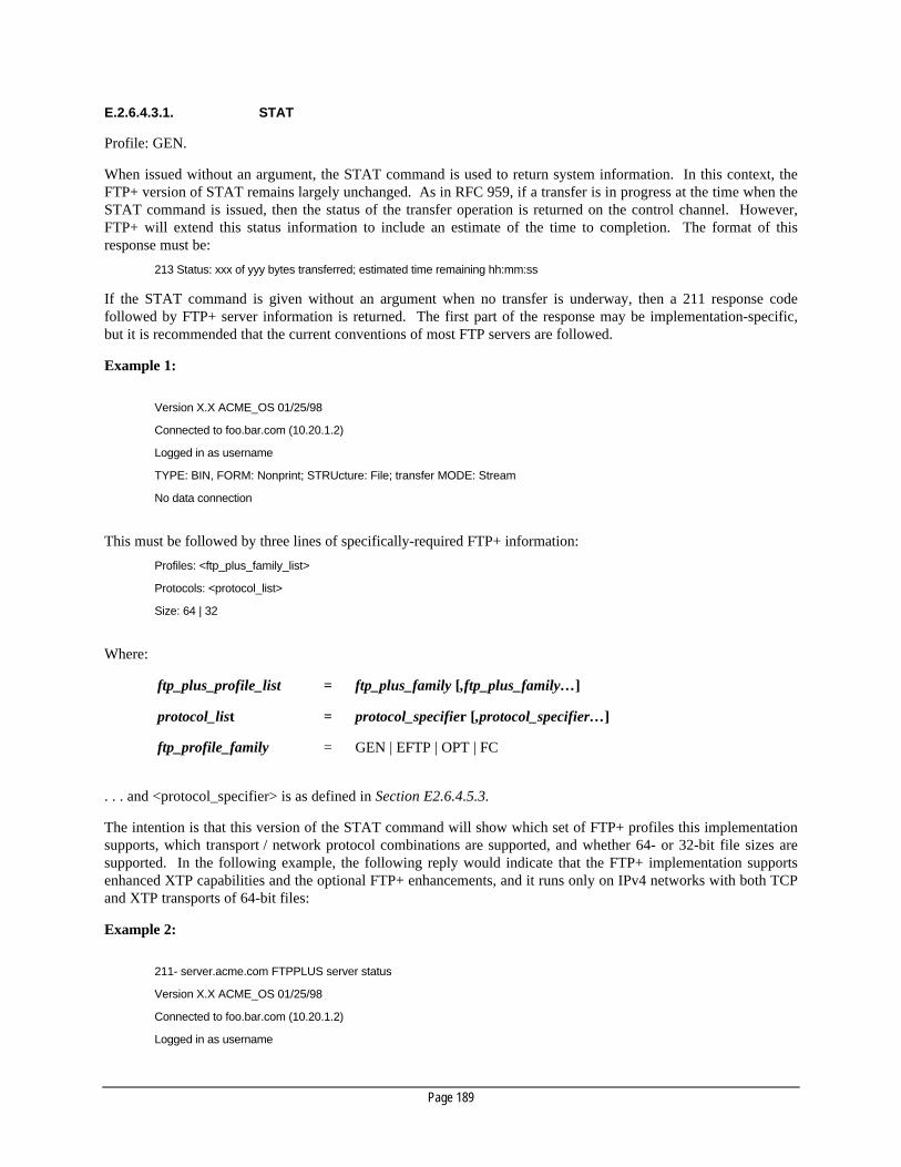
Page 189
E.2.6.4.3.1. STAT
Profile: GEN.
When issued without an argument, the STAT command is used to return system information. In this context, theFTP+ version of STAT remains largely unchanged. As in RFC 959, if a transfer is in progress at the time when theSTAT command is issued, then the status of the transfer operation is returned on the control channel. However,FTP+ will extend this status information to include an estimate of the time to completion. The format of thisresponse must be:
213 Status: xxx of yyy bytes transferred; estimated time remaining hh:mm:ss
If the STAT command is given without an argument when no transfer is underway, then a 211 response codefollowed by FTP+ server information is returned. The first part of the response may be implementation-specific,but it is recommended that the current conventions of most FTP servers are followed.
Example 1:
Version X.X ACME_OS 01/25/98
Connected to foo.bar.com (10.20.1.2)
Logged in as username
TYPE: BIN, FORM: Nonprint; STRUcture: File; transfer MODE: Stream
No data connection
This must be followed by three lines of specifically-required FTP+ information:
Profiles: <ftp_plus_family_list>
Protocols: <protocol_list>
Size: 64 | 32
Where:
ftp_plus_profile_list = ftp_plus_family [,ftp_plus_family…]
protocol_list = protocol_specifier [,protocol_specifier…]
ftp_profile_family = GEN | EFTP | OPT | FC
. . . and <protocol_specifier> is as defined in Section E2.6.4.5.3.
The intention is that this version of the STAT command will show which set of FTP+ profiles this implementationsupports, which transport / network protocol combinations are supported, and whether 64- or 32-bit file sizes aresupported. In the following example, the following reply would indicate that the FTP+ implementation supportsenhanced XTP capabilities and the optional FTP+ enhancements, and it runs only on IPv4 networks with both TCPand XTP transports of 64-bit files:
Example 2:
211- server.acme.com FTPPLUS server status
Version X.X ACME_OS 01/25/98
Connected to foo.bar.com (10.20.1.2)
Logged in as username

Page 190
TYPE: BIN, FORM: Nonprint; STRUcture: File; transfer MODE: Stream
No data connection
Profiles: EXTP, OPT
Protocols: /TCP/IP4, /XTP/IP4
Size: 64
211 End of status
E.2.6.4.3.2. SITE RATE | META | CONT
Profile: OPT.
These extended variants of the RFC 959 SITE command will return some additional information regarding thefeatures provided by the Optional profile. This information is returned as text responses to these commands.
The response to the SITE RATE command will be:
200 <maximum_rate>
. . . where maximum_rate (a decimal number of bytes per second) is the largest value accepted as an argument tothe FTP+ RATE command.
The response to the SITE META command will be:
200 [NO | YES] (The _META option is [or is not] supported)
. . . which specifies whether or not the _META option is supported by the STAT, LIST, STOR, RETR and NLSTcommands.
The response to the SITE CONT command will be:
200 [NO | YES] (The _ESSENCE option is [or is not] supported)
. . . which specifies whether or not the _ESSENCE option is supported by the STAT, LIST, STOR, RETR andNLST commands.
E.2.6.4.4. Overview of multicast transfers
Multicast transfers are supported by XTP, either in “raw” mode or over IP.. However, the FTP+ has been designedto encompass other transports which may support multicast data transfers. To perform a multicast transfer, oneserver must first create a multicast group which other receivers will then join. The multicast group will beidentified by a unique address that the sending server determined when it created the group. When the sendingserver later sends any data to this address, the underlying transport protocol will transmit this data in packets thatwill be received by each member of the group.
The XTP protocol was designed with the intention of supporting this type of operation. Specifically, it providescapabilities for multiple receivers to acknowledge the receipt of these multicast packets and to request, if need be,retransmission of lost packets.

Page 191
E.2.6.4.5. Multicast transfer commands
These commands are used when the enhanced XTP option is being supported to provide multicast transfercapabilities.
E.2.6.4.5.1. RATE <rate_value> [<burst_value>]
Profile: EXTP.
The RATE command is added by FTP+ to allow a client to set the maximum transfer rate that will be used duringthe data transfer. The rate_value specifies the maximum average transfer rate and the burst_value specifies themaximum burst transfer rate. Both of these values are given as decimal bytes per second to be used in a transfer.The SITE RATE command (see Section E.2.6.4.3.2.) can be used to determine the maximum value supported by anFTP+ server. This command is only applicable to XTP which inherently supports this type of rate throttling.
E.2.6.4.5.2. MCGM Leaves [Yes | No]
Profile: EXTP
The “MultiCastGroupManagment (MCGM) command” controls (and shows) what the policy should be for FTP+servers which attempt to join or leave a multicast group while a transfer is in progress. If set to “No”, then thesending server will abort the transfer and will return an error code and message on the control channel. If set to“Yes”, and at least one receiver still remains in the group, then the transfer will continue normally. If given withno arguments, the response to the MCGM command should be the current setting.
E.2.6.4.5.3. MCPV <protocol_specifier>
Profile: EXTP
The “MultiCastPassiVe (MCPV) command” is analogous to the XPSV command (see Section E.2.6.4.1.4.). Theargument <protocol_specifier> is exactly the same. The purpose of the MCPV command is to request that thereceiving FTP+ servers create a multicast group and return the <end_point_address> for that group so that it can besent to the receiving FTP+ servers in an MCPT command.
The only transport that can currently support multicast transfers is XTP. A <protocol_specifier> is included in thistransport so that future transports which support multicast can also be included.
E.2.6.4.5.4. MCPT <protocol_specifier> <end_point_address>
Profile: EXTP
The “MultiCastPorT (MCPT) command” is analogous to the XPRT command (see Section E.2.6.4.1.2.). Thearguments <protocol_specifier> and <end_point_address> are exactly the same. The purpose of the MCPTcommand is to make it unambiguous that the specified <end_point_address> is a multicast address. The FTP+server that receives an MCPT command does not simply establish a connection to the <end_point_address> as inthe case of an XPRT command. Instead, it must join the multicast group corresponding to that address. Theunderlying system calls that perform these two tasks will be different. By having a separate MultiCastPorTcommand, it is clear (without relying on interpreting the address given) that a multicast connection is desired.
E.2.6.4.6. Examples of multicast transfers
In this first example, we will consider the non-proxy case where there is client code running on the sending serverwhich wishes to send Content to three receiving FTP+ servers. First, this client code must obtain a multicast

Page 192
address (i.e. group) to use. Next, it must establish TCP control connections to each of the receiving FTP+ servers.Then, it will then issue MCPT commands to each of the receiving FTP+ servers. For example:
MCPT / XTP / IP 224.0.0.2:1234
200 Command Okay
This statement informs each receiving server that the multicast IP address 224.0.0.2 and XTP port 1234 will beused for this transfer. Next, the client code would issue STOR commands to each of the receiving FTP+ servers.Upon receipt of the STOR command, the receiving FTP+ servers would join the multicast group using, the address224.0.0.2:1234, and would wait for data to arrive. Finally, the client code on the sending host can start writing datato the multicast address which will then be received by each receiving FTP+ server. After all of the data has beenwritten, the client code on the sending server would close the multicast group. Each receiving FTP+ server woulddetect this and finish writing data to its Content and would then write completion information back to the clientserver via the control channel.
In the second example, we will consider the proxy case in which the client code is running on a machine notparticipating in either the sending or receiving of the data. This client code would first establish TCP controlchannels to each of the involved FTP+ servers. Next, it would issue an MCPV command to the sending FTP+server which would then return the multicast address that has been assigned for this transfer. For example:
MCPV / XTP / IP
229 (/ XTP 224.0.0.1:4623) Entering passive mode
At this point, the client will send MCPT commands to each of the receiving FTP+ servers, using the multicastaddress returned by the MCPV command as in the first example. Next, the client will send STOR commands toeach of the receiving FTP+ servers, which will cause them to join the multicast group. To start the actual transfer,the client will then send a RETR command to the sending FTP+ server. Once the transfer has finished, the clientwill receive completion information from all the involved parties via their respective control channels.
E.2.6.5. Writing commands for an FTP+ server
A particular implementation of FTP+ will probably not support all profiles, transports and network protocols. Todo so, would entail a very large and complex piece of software. Instead, the writer of commands for an FTP+ servermay wish to adopt the following implementation guidelines.
The FTP+ server can logically be divided into (i) a Core Component that receives most of the GEN or OPT profilecommands involved in defining the mode of operation of the FTP+ server and (ii) Transport Components which areresponsible for reading / writing Content data and sending / receiving this data over a particular transport.
E.2.6.5.1. The Base Component
The Base Component should be responsible for handling the GEN profile commands which are not related to anyform of file transfer. These include the SITE commands, MODE, STRU, TYPE, LIST, NLST and STAT (with noarguments and no transfer in progress). The Base Component should also be responsible for looking for the “portcommands” (i.e. PORT, XPRT, PASV and XPSV) to invoke the other components. One of the “port commands” isalways required before issuing any other commands which will send data over a data connection. By looking at theparticular “port command”, the Base Component can determine if the requested transport and network protocolsare supported. If they are it can then determine whether an XTP, TCP or FC component should be invoked tohandle it.
Once a Transport Component is invoked, the Base Component will continue to process any Content manipulationcommands, either involving the OPT profile for extended Content Identifiers or not. Once Content to betransferred has been located, a handle to this Content – along with the command and arguments – will be passed tothe Transport Component.

Page 193
E.2.6.5.2. Transport components
These components implement the actual sending / receiving of data over the data connection of a particulartransport.
• The TCP component will perform all operations which involve sending the data over a TCP connection. Asthis is the standard case (and is required for sending LIST or NLST data), it may be incorporated into the corecomponent.
• The XTP component will perform all operations which involve sending the data over an XTP connection. Thiscomponent will choose to implement either only the standard XTP operations (i.e. no multicast) or the full set.
• The FC component will perform all operations which involve sending the data over a Fibre Channelconnection.
E.2.6.6. Miscellaneous FTP+ issues
E.2.6.6.1. Detecting partial Content transfer
FTP, as specified in RFC 959, has difficulty with Stream mode in detecting the difference between a broken dataconnection and the end of the data connection, because the receiving FTP server sees both cases as a closedconnection. Block mode can provide a solution to this problem, but it is not supported by all FTP implementations.In the case where a sending or receiving FTP+ server crashes while in the process of performing a transfer, the factthat the control channel will also break can be used to detect that the whole Content may not have been transferred.
If the data channel breaks while the sending server is still writing data, the sending server will detect this conditionand will send an error message over the control channel. However, if the data channel breaks near the end of atransfer, it is possible that the sending server may already have written all of its bytes into the system buffer, butthat not all of these bytes have been emptied from the buffer and acknowledged by the receiving server. To solvethis problem, the FTP+ specification proposes to enhance the reply response to the STOR command by includingthe number of bytes written to permanent storage and to enhance the RETR command by including the number ofbytes written to the network. Using this enhancement, the client code on another FTP+ server should be able toverify that this number matches the number of bytes sent / received by it.
E.2.6.6.2. Restarting failed transfers
RFC 959 provides Block mode as a way to “checkpoint” data transfers. This is very important when two machinesdo not have the same byte size, or do not use Record Structures. However, since 8-bit byte sizes are now universaland Content Essence is universally stored as a byte stream, this problem can largely be solved by knowing howmany bytes a server has successfully written.
To this end, STOR and RETR should include in their reply codes the number of bytes written or transmitted, evenwhen the transfer is interrupted by a data channel connection failure. Then using the optional <start_byte_offset>and <length> arguments to STOR and RETR, a client can restart a failed transfer. In the case where an FTP+server crashes, the STAT command can be used to determine the size of the file that was created on the receivingserver to determine how much of it was successfully transferred.
E.2.6.6.3. Multi-homed hosts
When an FTP+ server is connected to more than one type of network interface, it can become problematic toperform certain types of transfers. One solution is to state that the interface on which the control channel has beenestablished should be the interface for all data connections. For FTP+, this does not work well because of thevariety of data channels supported and the lack of simple TCP connections on each type of transport protocol.

Page 194
For example, consider the case of a server that has three Ethernet interfaces; one supports TCP/IP and the other twosupport raw XTP. A client program then wishes to initiate a two-server transfer between this server and anotherFTP+ server, using XTP on one of the XTP Ethernet interfaces. To do so, it must state on which interface it wishesthis server to listen for a connection (i.e. on which interface it should perform the XPSV command). Theadditional XPSV command argument interface_name addresses this problem. It assumes, however, that the clientprogram knows the “name” of the interface on which it wants the server to listen.
E.2.6.6.4. Fibre Channel addressing and FTP+ commands
The syntax for addressing Fibre Channel data connections is still not known at the time of writing (July 1998).More information concerning the use of Fibre Channel will be required before this issue can be resolved.Additionally, the FTP+ command set may need enhancements to support the setting up of a Fibre Channelconnection (for example, buffer sizes). As the work of the Fibre Channel group proceeds, the FTP+ protocol mustbe enhanced as required to support these additional features.
E.2.6.6.5. “Raw-mode” XTP
The use of XTP without IP may be considered as optional. The benefits of using “raw-mode” XTP are limited atthe present time. In the future, it is possible that “raw-mode” XTP might take advantage of the underlying physicalmedia, for example using ATM QoS to implement the transfer rate setting. However, at the time of writing, nosuch capability exists. “Raw-mode” XTP does offer some small increase in efficiency at the present time, but this isnot a significant factor.
E.3. Streaming
E.3.1. Scope
This section provides an introduction to the means by which television programme material may be streamed overtransport technologies. A description of the processes, technologies and issues associated with streaming isprovided, together with an overview of current practice.
E.3.2. Introduction to Content streaming
Streaming is the transfer of television programme material over a transport technology from a transmitter to one ormore receivers, such that the mean reception frame-rate is dictated by the transmission frame-rate. The transmitterplays-out the material without receiving feedback from the receivers; consequently there is no capability for flow-control or for the re-transmission of lost or corrupt data. It is a continuous process in which the transmitter“pushes” programme material to receivers that may join or leave the stream at any time. The transmission frame-rate is not necessarily equal to the material’s original presentation frame-rate, thus allowing faster- or slower-than-real-time streaming between suitably-configured devices.
E.3.2.1. Stream containers
Digital television programme material consists of Video, Audio and Data Essence, along with Metadata elements,which are segmented, multiplexed together and encapsulated within containers. Containers are transferred by thetransport technology and include timing information to enable the receiving devices to synchronize the material’sreception rate to its transmission rate; they may also provide mechanisms for the detection and correction of errors.
Page 195
A variety of element formats and container types are used within the television industry, and internationalstandards define the rules for mapping between them. Certain types of containers are capable of encapsulatingother containers, thus allowing the creation of hierarchies of programme material.
E.3.2.2. Transport technologies for streaming
The ideal transport technology for the streaming of programme material would provide a lossless and constant-delay channel. In practice, few networks exhibit such qualities and it is therefore important to select atransportation technology that supports the desired streaming requirements. To achieve this, it is first necessary todefine the bounds within which the streaming is to be performed. This is achieved through the specification of a setof Quality of Service (QoS) parameters which include bit-rate, error-rate, jitter, wander, and delay andsynchronization aspects.
The specification of QoS parameters is based on the requirements of the container and the application. Containerrequirements might include bit-rate and jitter; application requirements might include error-rate and delay. Theselection of a particular transport technology is therefore based upon its capability for providing the required QoS.In some circumstances however, the suitability of the transport technology is also dependent upon the design of thedevices being used to map the containers to that transport technology (e.g. the capability of the jitter removalsystem).
Network transport technology should support the transparent routing of streams over multi-node network topologiesbetween devices identified through a unique address. Additional capabilities, such as mechanisms for multicastingstreams in point-to-multipoint applications, are also beneficial.
E.3.2.3. Mapping stream containers to transport technologies
In order to transport streams over networks, it is necessary to use standards-based rules that define how thecontainers are mapped to and from the network transport technology, using network protocols. The mapping rulesdefine how containers are segmented and reassembled, how synchronization is achieved and how error correctionand detection are performed.
In a number of cases, standards bodies have defined, or are in the process of defining, such mapping rules. In caseswhere no mapping exists, the EBU / SMPTE Task Force will decide if a mapping will be of value (whereupon theappropriate standards bodies will be solicited) or will deem the mapping inappropriate. Fig. E.4 provides aReference Architecture showing the relationship between the functions.
The function marked “Container Mapping Rules” places the Content as a sequence of bits into a container (e.g. amultiplex). The function marked “Transport Mapping Rules” places the container into the data payload section ofa selected underlying transport. This mapping is either performed through the use of a protocol (e.g. MPEG-2 TSpayload into ATM, using the ATM AAL1 protocol) or through a direct mapping of the payload into frames (e.g.SDI).

Page 196
Uncompressed 601
MPEG
DV
MPEG (TS, PS, etc.)
DV / DIF Stream
FC-AV
CP
AAL
SDTI
ATM
SDI
SDH / SONET
FC Physical
FC Class
RTP / RSVP
IP (TCP, UDP, etc)
Ethernet, etc
Application
Network (transport mechanisms)
Data Link &
Physical
Compression and Packetization
Transport Mapping Rules
Video
Audio
Data
Container
Figure E4: Stream delivery over selected packetized transports.
E.3.2.4. System-level issues for streaming
The control of streaming devices requires the implementation of communication protocols and interfaces thatprovide capabilities for the following:
E.3.2.4.1. Initiation and termination of streaming
• configuration of the sending devices (e.g. bit-rate, MPEG-2 GoP structure etc.);
• selection of material to stream;
• configuration of multicast;
• access control mechanism.
E.3.2.4.2. Joining and leaving streams at the receiver
• configuration of receiving devices;
• selection of stream to join;
• access control mechanism.
E.3.2.4.3. Management of the service
• accessing network performance data (e.g. SNMP);

Page 197
• define the management information base (MIB) including monitor points and controls;
• providing remote access to performance data, e.g. Simple Network Management Protocol (SNMP).
No such protocols have currently been standardized and proprietary schemes are likely to prevail for the foreseeablefuture.
E.3.3. Considerations when streaming
The implementation of a Content streaming solution requires the following issues to be examined:
• Quality of Service requirements;
• Error Management capabilities;
• Timing and Synchronization;
• Addressing and Routing;
• Mapping streaming containers between transport technologies;
• Tunneling and Bridging.
These issues are discussed in detail below.
E.3.3.1. Quality of Service
The following QoS parameters provide a basis for determining the suitability of a transport technology forstreaming.
• Peak bit-rate (bit/s) – the bit-rate which the source may never exceed.
• Minimum bit-rate (bit/s) – the bit-rate at which the source is always allowed to send.
• Sustained bit-rate (bit/s) – the mean bit-rate at which the source transmits.
• Jitter (or Delay Variation).
• End-to-end delay (seconds) – i.e. propagation delay.
• Bit Error Rate (errors/bit) – the average number of errors per bit.
• Set-up delay (seconds) – the maximum delay between requesting a connection and receiving it.
It is recognized that some transport technologies permit other QoS parameters to be defined. These may beincluded in the mapping if necessary.
E.3.3.2. Error management
The implementation of a suitable error management system is essential for the streaming of high-quality Contentover network technologies, since none provide completely error-free transport.
Error management is achieved through the implementation of mechanisms that provide error correction or errorconcealment. In either case, it is first necessary to detect the error in the streamed Content. Re-transmission isusually not possible due to the timing relationship that exists between the transmitter and the receiver. Theselection of the error management mechanism is determined by examining the QoS requirements of the streamingapplication and the QoS characteristics of the transport technology. To realize any level of error management, atransmission overhead is necessary.

Page 198
E.3.3.2.1. Error detection
Error detection enables the identification of lost or corrupt data. The granularity of error detection (i.e. whethererrors are detected at the bit level, container level or frame level) plays a large part in the success of the errorconcealment.
E.3.3.2.2. Forward Error Correction
Forward Error Correction (FEC) enables the recovery of corrupt or lost data through the addition of redundancy inthe stream. This typically introduces an overhead. There are a number of different FEC mechanisms, bothproprietary and standards-based (e.g. ITU-T J.82 Reed-Solomon FEC for MPEG-2 over ATM, and ATSC A53FEC).
E.3.3.2.3. Error concealment
Error concealment enables the effect of lost or corrupt data to be masked through the implementation of techniquessuch as replication and interpolation. The success of error concealment is dependent upon the sophistication of theerror detection mechanism and the redundancy embedded in the Content.
E.3.3.3. Synchronization
Streaming data requires timing synchronization between the transmitters and receiver(s). This timingsynchronization may be achieved through either the recovery of timing references embedded within the stream, orthrough the distribution of a system-wide clock to all participating devices.
In a transport environment there are two aspects to synchronization; the synchronization of the stream and thesynchronization of the transport technology. The list below identifies a selection of video service synchronizationtolerances (transport technology tolerances are outside the scope of this document):
• Composite video timing requirements are constrained by 0.23 ppm (PAL) and 2.8 ppm 22 (NTSC) as defined inITU-R 470.
• Component video clock accuracy in hybrid environments is constrained to that of composite video.
• For MPEG Transport Streams, the System Clock accuracy is constrained by 30 ppm as defined in ISO 13818-1.
• SDTI, as defined in SMPTE305M, provides frame and line synchronization facilities through the use of theSDI interface according to ITU-R BT.656.
DV, as a deterministic system, uses a system of clocks directly related to 13.5 MHz. The DV clock is phase-lockedto the main clock of the 525- and 625-line TV systems, and so its accuracy is the same as for the basic 525- and625-line systems.
The proposed standard for carrying MPEG-2 Transport Streams (SDTI-TS) over SDTI defines that incomingMPEG Transport Packets are justified to one line length. The input and output receiver buffers will need to have abuffer capability of 1 line in order to buffer a constant TS bitstream at the input and output.
It is necessary for streaming receivers to implement mechanisms to remove any jitter introduced by the networktechnology in order to ensure the accuracy of the recovered stream time references.
22 ±10 Hz / 3,579,545 Hz.

Page 199
E.3.3.4. Addressing and routing
Connections over transport technologies may be pre-defined or created dynamically. In either case, theimplementation of an addressing scheme is necessary to identify the attached devices. The addressing schemeenables each attached device (i.e. transmitters and receivers) to be identified uniquely. The means through whichthis is achieved is dependent upon the transport technology. Typical addressing schemes are IP (v4 and v6), NSAP,E.164 etc.
Methods for routing streams over network technologies is beyond the scope of this document. Nevertheless, it canbe stated that the routing function should be transparent when establishing connections between streaming devices.
E.3.3.5. Local- and wide-area streaming
Streaming is performed both within a facility and between facilities. Different considerations are required for eachapplication. Local-area streaming within the facility is performed over a network that is owned and managed bythe facility whereas wide-area streaming is generally performed over a network owned by a third-party serviceprovider and which is shared between many subscribers. Consequently, differences in technology, scalability,economics, performance and QoS must be taken into account.
Many network technologies deployed within the local area are not suitable for use in the wide area, due to theirrestricted transmission distance and limited capability for scaling to large numbers of nodes. Conversely, networktechnologies for the wide area are often not economic for use in the local area. Local-area network technologiesused within a facility include SDI / SDTI, Fibre Channel, ATM, IEEE 1394 and the DVB family. ATM isgenerally used to provide wide-area connectivity between facilities (over PDH or SDH / SONET). Consequently,gateways are required to provide inter-working between local-area technologies and wide-area technologies.
There are differences in the performance and QoS characteristics of local- and wide-area technologies. Theseinclude bandwidth, latency, jitter and synchronization.
E.3.3.6. Mapping containers between transport technologies (bridging)
Containers may be mapped from one transport technology to a different transport technology. This function isprovided by gateways that are capable of supporting two or more transport technologies. The mapping is reversibleand does not alter the Content or structure of the container.
Mapping will necessarily introduce delay, and re-timing (e.g. updating timing references within the container) maybe necessary to meet synchronization requirements.
A bridging function is often required between a local studio network and a wide-area network, due to the differentnetwork technologies employed therein. Examples include the mapping of DIF blocks from SDTI to FCS, andMPEG-2 TS from FCS to ATM.
E.3.3.7. Tunneling
Tunneling is a way of transporting a complete interface data structure, including payload, through anotherinterface; for example, IP over SDTI. IP multicast can then be used to transport both Data Essence and Metadatawhich are associated with the SDTI Audio / Video Essence carried in the main SDTI programme.
E.3.4. Supported mappings of containers to transport technologies
A mapping of container-to-transport technologies is provided in Section 5.7.3.

Page 200
E.3.4.1. Overview of containers
E.3.4.1.1. The DV family
The DV compression family consists of a number of different schemes which are summarized as follows:
• DV Consumer at 25 Mbit/s:
– 4:2:0 sampling in 625/50 countries;
– 4:1:1 sampling in 525/60 countries.
• DVCPRO at 25 Mbit/s in 525 and 625 countries (4:1:1 sampling);
• DVCPRO50 at 50 Mbit/s in 525 and 625 countries (4:2:2 sampling);
• Digital S at 50 Mbit/s in 525 and 625 countries (4:2:2 sampling);
• DVCAM at 25 Mbit/s:
– 4:2:0 sampling in 625/50 countries;
– 4:1:1 sampling in 525/60 countries.
All the compression schemes share the so-called DIF (Digital Interface) structure which is defined in the “BlueBook” (IEC 61834).
• Each DIF block is 80 bytes; comprising 3 bytes of header and 77 bytes of payload;
• A DIF sequence is composed of 150 DIF blocks;
• In the 25 Mbit/s version, a DIF frame consists of either 10 DIF sequences (525-line system) or 12 DIFsequences (625-line system). In the 50 Mbit/s version, the number of DIF sequences per frame is double that ofthe 25 Mbit/s version.
The Content of DIF blocks and the number of sequences will depend on the compression scheme and on the bit-rate(25 or 50 Mbit/s).
E.3.4.1.2. The MPEG-2 family
The ISO 13818 2 standard defines the following containers:
• Elementary Streams (ES). An MPEG-2 ES is a continuous stream which contains no timing information orheaders. The transport of ES requires the addition of timing information.
• Packetized Elementary Streams (PES). MPEG-2 PES packets include timing and headers and are variablelength (up to 64k).
• Programme Stream Packets (PS). MPEG-2 PS packets are 188 bytes long and contain only a singleprogramme with embedded timing information.
• Transport Stream Packets (TS). MPEG-2 TS packets are 188 bytes long and support a multiplex ofprograms with embedded timing information.
E.3.4.2. Transport technologies appropriate to streaming
E.3.4.2.1. SDI- and SDTI-based streams
SDTI, as defined in SMPTE 305M, uses the SDI interface according to ITU-R BT.656 as the physical transportsystem. Because of its TV frame-synchronous nature, SDTI is well suited for use in real-time critical applicationssuch as streaming Content. The Content to be streamed is inserted in the predefined SDTI packets and thereforeframe synchronization is automatically achieved. Because of the use of the SDI / ITU-R BT.656 interface, the dataintegrity depends on the performance parameters (BER, jitter, delay) determined by the SDI interface.
Page 201
SDI is a unidirectional interface without re-transmit capabilities for corrupted data. Consequently, SDTI packetscan be corrupted as well. In order to overcome this fact, Content needs to be protected by FEC.
SDTI streaming allows real-time streaming and faster-than-real-time streaming. For example, in a 270 Mbit/s SDIenvironment using SDTI, a payload rate of about 200 Mbit/s is achievable. Subtracting further overheads due tosignaling etc., a 50 Mbit/s compressed video stream can easily be transferred at twice real-time speed.
Although SDTI provides addressing capabilities, its use in a streaming environment will be limited to point-to-point or point-to-multipoint applications. Usually the Content is headed by control packets for the receiving device.Examples of such control packets are machine control parameters or transfer speed information.
Each application which takes advantage of SDTI requires (i) full documentation of the data to be transmitted (e.g.DV or MPEG-2 ), (ii) the data structure of the source stream to be inserted (DIF or MPEG TS including the controlinformation, if used) and (iii) the mapping of the source stream into the structure provided by SDTI.
E.3.4.2.2. ATM-based streams
ATM is suitable for streaming digital television programme material over both the local and wide area, andstandards have been defined for the transport of MPEG-2 Transport Streams.
The following issues are addressed by the standards:
• Service Class Selection;
• mechanisms for MPEG-2 Transport Packet encapsulation;
• clock synchronization and de-jitter;
• error detection and correction.
MPEG-2 requires an ATM service-class that is connection-oriented and which supports real-time transfer. Class A(CBR) and Class B (VBR-RT) service classes support these requirements. However, the current (July 1998)immaturity of standards for Class B invariably means that Class A is used.
The MPEG-2 Transport Stream that is presented to the ATM adaptation must therefore also be CBR. This isachieved within MPEG-2 encoders by the use of buffering and the implementation of a rate control mechanismwhich alters the quantization level (and hence the bits per frame).
The AAL defines how the MPEG-2 Transport Stream (TS) mapping, error handling and synchronization areperformed. The selection of the appropriate AAL is important since it has a significant impact on the QoS. TheITU-T J.82 standard specifies how either AAL1 (CBR) or AAL5 (VBR) can be used for MPEG-2 streamingapplications.
The mapping of MPEG-2 Transport Streams to ATM cells is specified by the AAL Segmentation and Re-assemblyfunction. An MPEG-2 Transport Stream consists of 188-byte packets which must be mapped into the 48-bytepayload of the ATM cells. AAL1 uses one of the payload bytes for sequence numbering (which enables thedetection of lost cells), thereby allowing an MPEG-2 TS packet to be mapped into exactly four ATM cells. AAL1allows two MPEG-2 TS packets to be mapped into eight ATM cells (together with the CPCS-PDU trailer).
MPEG-2 uses a 27 MHz system clock to synchronize the operations of the decoder to those of the encoder. Thesynchronization of the clocks is achieved through the use of MPEG-2 TS Programme Clock References (PCRs). Anideal network maintains a constant delay between each PCR. In practice, the CDV within the ATM cell stream canresult in unacceptable PCR jitter at the decoder. It is therefore necessary to implement mechanisms for overcomingthe jitter.
AAL 1 is CBR and it provides two mechanisms for timing recovery: Synchronous Residual Time Stamp (SRTS)and Adaptive Clock Recovery. Since AAL 5 is VBR, Adaptive Clock Recovery is used. It should be notedhowever, that the jitter-removal capability of all ATM devices is design-dependent.

Page 202
Error-correction and detection mechanisms can significantly improve the quality of the received stream. TheAAL 1 specification (ITU-T I.363) includes a FEC and byte interleaving mechanism that is capable of recoveringup to four lost cells in a group of 128 cells. In addition, the cell sequence numbering provided by AAL 1 allowserrors to be detected on a per-cell basis, thus aiding error concealment. The AAL 5 specification contains nomechanism for error correction and thus the error detection takes place at the SDU level.
Although the ATM Forum recommends the use of AAL 5 for consumer-quality Video-on-Demand (VoD) services,the benefits of low jitter and standards-based error detection and correction have led the DVB Project to recommendthe use of ATM with AAL 1 for the transport of professional quality video over PDH and SDH networks (see theETSI Standards, ETS 300 813 and ETS 300 814). AAL 1 is therefore recommended for the transport of MPEG-2TS packets over wide-area networks.
E.3.4.2.3. IP-based streaming
IP (Internet Protocol) streaming is not synchronous compared to the video delivery rate. Synchronization ofstreams over IP therefore requires timing references to be embedded within the stream. IP streaming requires thesupport of IETF RTP (Real-time Transport Protocol). RTP permits real-time Content transport by the inclusion ofmedia-dependent Time Stamps that allow Content synchronization to be achieved by recovering the sending clock.RSVP (Resource reSerVation Protocol) provides network-level signaling to obtain QoS guarantees.
RSVP is a QoS signaling protocol for application-level streams (called “flows” in the IP community) and is definedby a number of RFCs. The most relevant are: RFC 2205 (Protocol Specification), RFC 2208 (ApplicabilityStatement) and RFC 2209 (Message Processing).
Session-control protocols for streaming (in draft form, July 1998) include RTSP (Real-Time Sessions Protocol),SDP (Session Description protocol) and SAP (Session Announcement Protocol).
UDP, as defined in RFC 768, can be used as an option to enable bounded-quality transfers on top of the IP layer. Itallows broadcast transmissions and is a datagram-oriented protocol.
Some of the application scenarios for IP streaming are:
• Intranet, Internet browsing of Content (e.g. browsing an archive);
• Internet broadcasting (lectures, conferences, etc.);
• Web-based off-line editing;
• Web-based “channels” (IP-TV).
E.3.4.2.4. Fibre Channel-based streaming
Fibre Channel is suitable for streaming Content in local-area and campus-wide networks. Standards have beencompleted or are under development that can transport uncompressed material and Content streams. Thesestandards cover:
• Basic network services:
• Fractional Bandwidth services.
Work is underway on an extended FC standard that covers the following:
• Encoding and encapsulation of uncompressed Content;
• Simple container (Wrapper) model;
• DV compressed streams;
• MPEG Transport Streams.

Page 203
The FC Fractional Bandwidth service by itself does not provide the high-quality jitter control required by broadcastsystems. This can be accomplished using the Fractional Bandwidth service with another synchronizationmechanism.
Timing reference information can be embedded in the data stream (as it is in MPEG Transport Streams) or acommon clock can be used.
The FC-AV project has developed an additional bandwidth management scheme. This protocol can beimplemented using current FC hardware. This scheme uses larger buffers so that the additional jitter of a higher-level bandwidth management protocol can be supported.
Fibre Channel is defined by the following base standards:
• FC-PH (X3.230-1994) covering the basic interface;
• FC-PH-2 (X3:297-1997) which extends the basic network with the Fractional Bandwidth service, a Class 3(datagram service) multicast model and other enhancements;
• FC-AL (X3:272-1996) which defines the basic arbitrated loop model;
• FC-LE (X3:287-1996) which describes part of IP on FC models;
• FC-FCP (X3:269-1996) which describes SCSI-3 encapsulation on FCS.
Other work of interest includes:
• FC-PH-3 (X3:303-199x) which covers further enhancements to the basic interface, including higherbandwidth links and a multicast service for Class 1 (a connection based service);
• FC-AL-2 (Project 1133-D) which covers enhancements for arbitrated loops.
Work is also underway on protocols and other extensions for A/V applications in FC-AV (project 1237-D).
Page 204
Annex F: AcknowledgmentsGrateful thanks must be extended to all those people, and their generously supportive employers, who have workedlong and hard to create the two reports that have been the tangible output of the Joint EBU / SMPTE Task Force forHarmonized Standards for the Exchange of Programme Material as Bitstreams.
Particular mention must be made of the co-Chairmen of the Task Force, Merrill Weiss and Horst Schachlbauer,whose farsightedness and sense of purpose (not to mention their black belts in diplomacy) contributedfundamentally to the work process. Other than these, naming the people who really got to grips with the workthroughout the life of the Task Force would perhaps be invidious here, but they (and we) know who they are, andtheir standing in our industry is correspondingly, and deservedly, very high.
Meetings don't happen for free. Considerable investment in the hosting of meetings has been made in terms oftime, conference facilities and catering – in particular by Sony, the EBU, Microsoft, Turner EntertainmentNetwork, Panasonic, Philips, Planon Telexpertise and Pro-Bel. Their invaluable assistance to the Task Force hasbeen much appreciated.
Thanks must also go to the BBC Research and Development Department and David Bradshaw, in particular, whovery kindly provided the FTP site and the e-mail reflector which the Task Force has been using to great effect.
The intrepid Secretary to the Task Force throughout has been Roger Miles, of the EBU Technical Department. Hispatience with the Chairmen, and his persistence in pulling together the many undertakings of the Task Force, hasbeen, in many ways, the glue that has held the operation together.
Finally, mention must be made of Mike Meyer, Editor of the EBU Technical Review, who spent a considerableamount of his valuable time on the raw text and the layout, fashioning this report into an admirably lucid documentfor publication both by the EBU and the SMPTE.

Page 205
Annex G: Task Force participantsGiven below is a list of the individuals who participated in the deliberations of the Task Force and their companyaffiliations.
Name OrganizationABRAMS Algie MicrosoftACKERMANS Merrick Turner Entertainment Net.ACOSTA Juan IBMAGOSTON György MTV (Hungary)ALLBRITTON Robin C-CubeARDITO Maurizio RAIATKINSON Steve Avalon ConsultingBANCROFT Dave Philips DVSBANTHORPE Steve BTBASTANI Behzad Philips ResearchBEERS Andy MS NBCBENJAMIN Shai ECI TelecomBERNARD Frank SGIBIRKMAIER Craig Pcube LabsBIRKS David MitsubishiBOCH Laurent RAIBØHLER Per NRKBOUDIGUES Pierre TF1BRADSHAW David BBCBRATTON William F. Turner Broadcasting Syst.BRENNAN-TURKOWSKI Rita Apple Corp.BROOKS David Snell & WilcoxBRYDON NeilBUKOWSKI John QuantelCAMERON Don JVCCASTLE Gordon CNN R&DCHOU Philip A. MicrosoftCINQUINI Maurice Philips DVSCLAY Nicholas MicrosoftCOCKRAM Clare BBCCOLEY Bryan Turner Entertainment Net.COLLIS Ian Sony BPECOTTAM Seb Sony BPECUDEL Damian TF1DABELL AdrianDALE Andy AvidDARE Peter SonyDAVIS Franklin OMFDELAIGLE Jean-Francois UCLDIMINO Giorgio RAIDRISCOLL Sean Merrill Weiss GroupDUCA Jim ConsultantEBNER Andreas IRTEDGE Bob TektronixELMER Peter BT LabsEMMETT John BPR Ltd.FANKHAUSER Eric GennumFARJEON Marc Warner Bros.
Name OrganizationFELL-BOSENBECK Frank Panasonic B’castFENTON John C. Mentat Inc.FERNANDO Gerard Sun MicrosystemsFERRANTE-WALSH Lisa OMF / AVIDFIBUSH David TektronixFLORENCIO Dinei Sarnoff Corp.FUHRER Jack HitachiGABRIEL John The Duck Corp.GAGGIONI Hugo SonyGARSHA Chuck Paramount Pics.GILMER Brad Gilmer AssociatesGIROD Carl SMPTEGOLDSTONE Ira TribuneGOLMI Nada NISTGRAY Bob PlutoGUZIK Ken Sun MicrosystemsHAAS Norman IBMHARRIS Brooks B. Harris Film & TapeHART Jim Panasonic B’castHAYCOCK David Artel VideoHEDTKE Rolf FH WiesbadenHEITMANN Juergen AV Media Tech.HILKES Rob GennumHOFFMANN Hans IRTHOPPER Richard BBCHORI Akihiro NTVHULME Pete SagittaHUNTER Kurt MicrosoftIDE Akifumi MatsushitaIRVIN Martin Sony BPEIVE John G.S. SonyIWASAKI Yasuo SonyJACOBY Ronald SGIJOHNSEN Reidar Otto NRKJONES Chris Drake AutomationJORGENSEN Chris NBCJULIAN Marcus Vibrint Tech.KAISER Martin RBTKANE Joseph ImagingScienceKAPUCIJA Tom GennumKEANE James NBCKELLEHER Terry Pathlight Tech.KERSHAW Sam ECI TelecomKISOR Robert Paramount Pics.KLEMETS Anders MicrosoftKNÖR Reinhard IRTKOBAYASHI Akira JVCKOLLER Herbert AMEC

Page 206
Name OrganizationKÖNIG Peter NDRKOVALICK Al H.P.LEE Henry MicrosoftLEGAULT Alain MatroxLEWIS Lisa Excell DataLIRON John TektronixLIU John C. SGILIVINGSTON Philip PanasonicLONG Stephen DOD / NIMALUAN Laura-Zaihua IBMMAIER George Artel Video SystemsMAJIDIMEHR Amir MicrosoftMALTZ Andrew Digital Media TechnologiesMARDER Stan The Duck Corp.MARSH Dave Snell & WilcoxMAYCOCK Neil Pro-belMCDERMID Edward AvidMcMAHON Thomas MicrosoftMIHARA Kanji SonyMILES Roger EBUMILLER William C. ABC-TVMILLER Daniel The Duck Corp.MINZER Oren ECI TelecomMORGAN Oliver AvidMORIOKA Yoshihiro MatsushitaMORRIS Ken IBMMURPHY Robert AvidNAGAOKA Yoshimichi JVCNAKAMURA Shoichi NHKNELSEN Don AvidNELSON Quentin Utah ScientificNEUBERT Neil JVCNEWELL Chris BBC R&DNICHOLSON Didier Thomson CSFNOTANI Masaaki MatsushitaNOURI Semir JVCNOVAK Ben MicrosoftODONNELL Rose AvidOSTLUND Mark HPOWEN Peter QuantelOZTEN Saruhan PanasonicPALMER Douglas VideoFreedomPALTER D.C. Mentat Inc.PAULSEN Karl Synergistic Tech. IncPENNEY Bruce TektronixPETERS Jean-Jacques EBUPIPPENGER Den VideoFreedomPITTAS John SeachangePOE C. VideoFreedomPOINT Jean-Charles Thomson TBSPOLGLAZE David Sony BPEPUGH Michael Digital AcousticsRADLO Nick JournalistRAHIMZADEH Auri Envisioneering Gp.RAHMAN Altaf PhilipsRAYNER Andrew BT LabsRODD Spencer Pharos
Name OrganizationROE Graham Pro-BelROMINE Jeff Philips BTSROSEN Andrew MicrosoftROSSI Gerry The Duck Corp.RYNDERMAN Richie Avid CinemaSADASHIGE Koichi NTASAFAR Johann PanasonicSAKAI Prescott Cypress S/CSAVARD Stéphane Planon TelexpertiseSCHAAFF Tim AppleSCHACHLBAUER Horst IRTSCHAEFER Rainer IRTSHELTON Ian NDSSHISHIKUI Yoshiaki NHKSIEGEL Jon Object Model GroupSLUTSKE Bob Nat. TeleConsultantsSMITH Garrett ParamountSMITH Clyde Turner Entertainment Net.STEPHENS Roger Sony BPESTEVENS Paul Silicon GraphicsSTOREY Richard BBC R&DSTREETER Dick CBSSUTHERLAND Joe C-CubeSUZUKI Tomoyuki JVCSYKES Peter Sony BPETANAKA Masatoshi MatsushitaTATSUZAWA Kaichi SonyTHIRLWALL Clive Sony BPETICHIT Bernard Thomson BroadcastTOBIN Bill SunTUROW Dan GennumWALKER Paul 4 LinksWALLAND Paul Snell & WilcoxWALTERS David Snell & WilcoxWARD Chris SarnoffWEINSTOCK Mitchell QuickTime Co.WEISS S. Merrill Merrill Weiss GroupWELLS Nicholas BBCWENDT Hans JVC GermanyWHITE Jason MicrosoftWILKINSON Jim SonyWODE Gary Wode DesignsWRIGHT Colin 7 Network AustraliaYAGI Nobuyuki NHKYATES Anthony Yates & Co.YONGE Mark Solid State LogicYOSHIDA Junko EE TimesZACCARIAN Paulo Consultant