sockets electric plug and socket connectors · rectangular connectors acc. to din en - -a form a,...
TRANSCRIPT

Sockets
Electric Plug and Socket ConnectorsFor pressure switches, level switches, flow sensors, directional control valves and filters
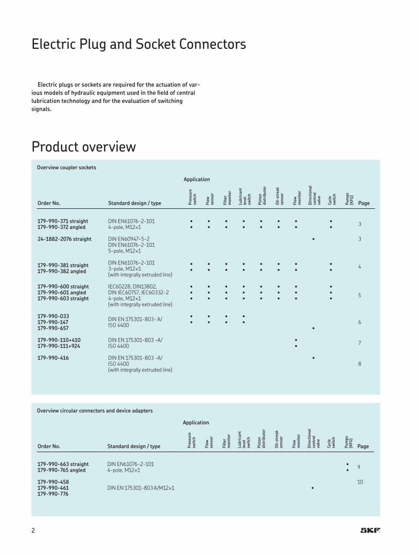
Product overview
Electric plugs or sockets are required for the actuation of var-
ious models of hydraulic equipment used in the field of central
lubrication technology and for the evaluation of switching
signals.
Electric Plug and Socket Connectors
Overview coupler sockets
Application
Order No. Standard design / type Pre
ssure
sw
itch
Flo
w
senso
r
Filte
r
monit
or
Lubri
cant
leve
lsw
itch
Pis
ton
dis
trib
uto
r
Oil-
stre
ak
senso
r
Flo
w
monit
or
Dir
ecti
onal
contr
ol
valv
e
Cyc
lesw
itch
Pum
ps
(KFG
)
Page
-- straight DIN EN--
-pole, Mו • • • • • • •
-- angled • • • • • • • •
-- straight DIN EN-- DIN EN---pole, M×
•
DIN EN---pole, M×(with integrally extruded line)
-- straight • • • • • • • •
-- angled • • • • • • • •
-- straight IEC, DIN, DIN IEC, IEC--pole, M×(with integrally extruded line)
• • • • • • • •
-- angled • • • • • • • •-- straight • • • • • • • •
--DIN EN -- A/ISO
• • • •-- • • • •
-- •
--+ DIN EN - -A/ISO
•
--+ •
-- DIN EN - -A/ISO (with integrally extruded line)
•
Overview circular connectors and device adapters
Application
Order No. Standard design / type Pre
ssure
sw
itch
Flo
w
senso
r
Filte
r
monit
or
Lubri
cant
leve
lsw
itch
Pis
ton
dis
trib
uto
r
Oil-
stre
ak
senso
r
Flo
w
monit
or
Dir
ecti
onal
contr
ol
valv
e
Cyc
lesw
itch
Pum
ps
(KFG
)
Page
-- straight DIN EN--
-pole, Mו
-- angled •
--DIN EN - A/M×
-- •--
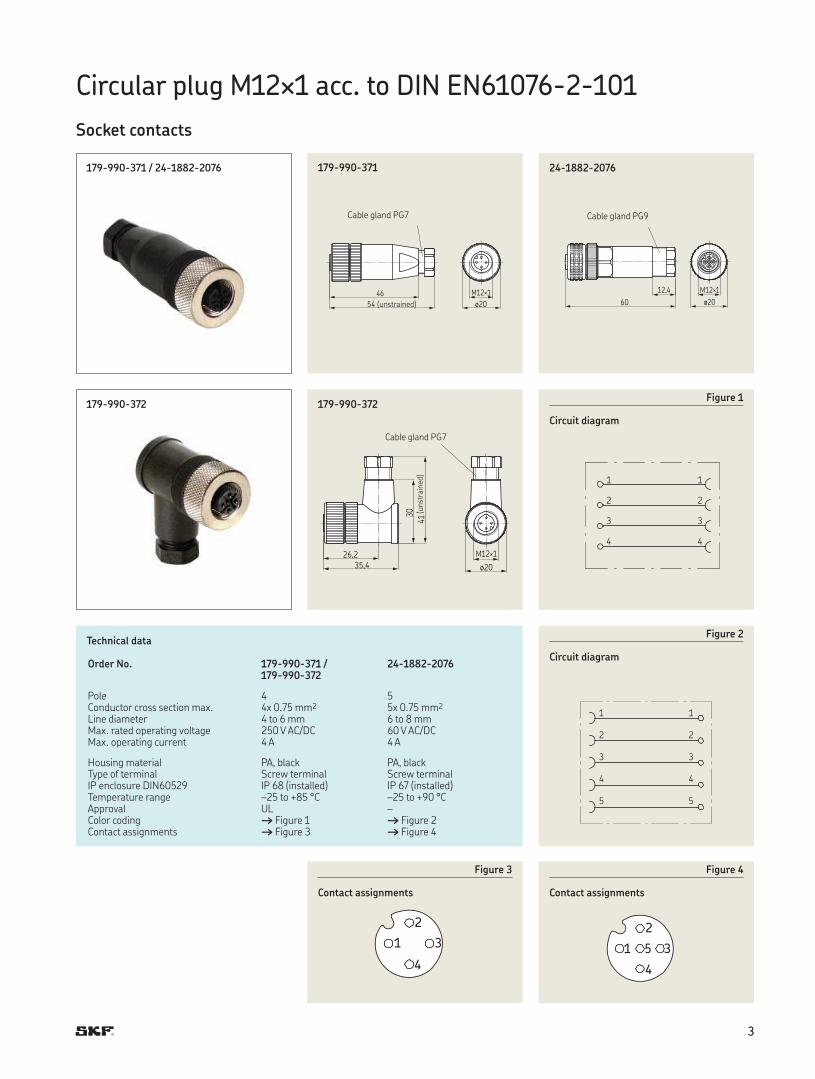
Circular plug M× acc. to DIN EN--
Socket contacts
-- / --
54
46
ø20
M12×1
--
60
12,4
ø20
M12×1
1
2
3
4
--
Technical data
Order No. -- / --
--
Pole Conductor cross section max. x . mm x . mm Line diameter to mm to mm Max. rated operating voltage V AC/DC V AC/DC Max. operating current A A
Housing material PA, black PA, black Type of terminal Screw terminal Screw terminalIP enclosure DIN IP (installed) IP (installed) Temperature range – to + °C – to + °C Approval UL –Color coding † Figure † Figure Contact assignments † Figure † Figure
--
ø20
M12×126,2
35,4
30
41
--
1 1
2 2
3 3
4 4
Figure
Circuit diagram
1 1
2 2
3 3
4 4
5 5
Figure
Circuit diagram
2
1 3
4
Figure
Contact assignments
Cable gland PG
2
1 5 3
4
Figure
Contact assignments
Cable gland PG
(unstrained)
Cable gland PG
(un
stra
ined
)
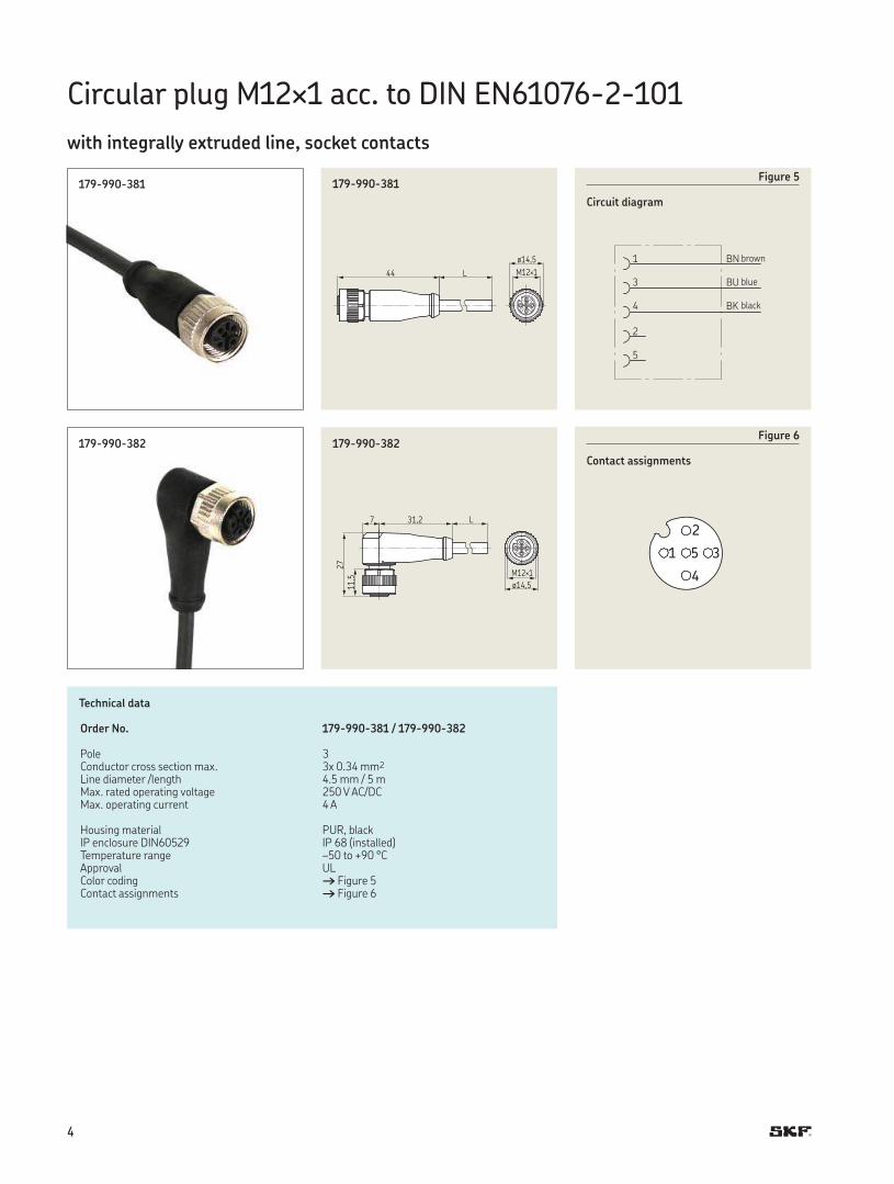
Circular plug M× acc. to DIN EN--
with integrally extruded line, socket contacts
--
ø14,5
M12×144 L
--
Technical data
Order No. -- / --
Pole Conductor cross section max. x . mm Line diameter /length . mm / mMax. rated operating voltage V AC/DC Max. operating current A
Housing material PUR, black IP enclosure DIN IP (installed) Temperature range – to + °C Approval ULColor coding † Figure Contact assignments † Figure
--
ø14,5
M12×1
31,2 L7
27
11,5
--
1 BN
3 BU
4 BK
2
5
Figure
Circuit diagram
2
1 5 3
4
Figure
Contact assignments
brown
blue
black
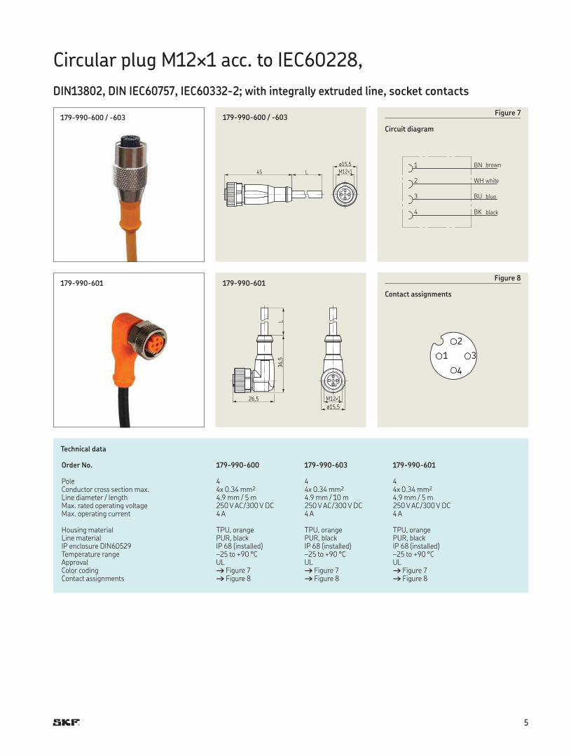
Circular plug M× acc. to IEC,
DIN, DIN IEC, IEC-; with integrally extruded line, socket contacts
-- / -
ø15,5
M12×145 L
-- / -
Technical data
Order No. -- -- --
Pole Conductor cross section max. x . mm x . mm x . mm Line diameter / length . mm / m . mm / m . mm / mMax. rated operating voltage V AC/ V DC V AC/ V DC V AC/ V DC Max. operating current A A A
Housing material TPU, orange TPU, orange TPU, orange Line material PUR, black PUR, black PUR, blackIP enclosure DIN IP (installed) IP (installed) IP (installed) Temperature range – to + °C – to + °C – to + °C Approval UL UL ULColor coding † Figure † Figure † Figure Contact assignments † Figure † Figure † Figure
--
ø15,5
M12×126,5
36,5
L--
1 BN
2 WH
3 BU
4 BK
Figure
Circuit diagram
2
1 3
4
Figure
Contact assignments
brown
white
blue
black
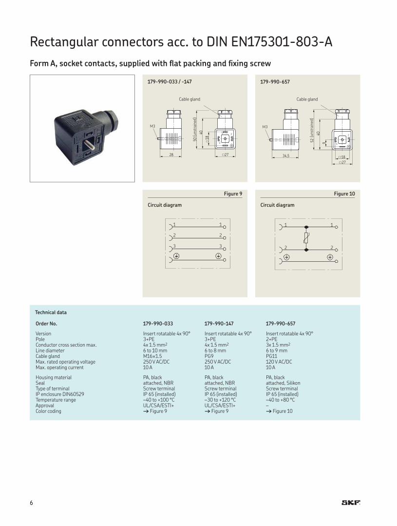
Rectangular connectors acc. to DIN EN--A
Form A, socket contacts, supplied with flat packing and fixing screw
2728
50
40
18
3 2
1
-- / -
Technical data
Order No. -- -- --
Version Insert rotatable x ° Insert rotatable x ° Insert rotatable x °Pole +PE +PE +PEConductor cross section max. x . mm x . mm x . mm Line diameter to mm to mm to mmCable gland M×. PG PGMax. rated operating voltage V AC/DC V AC/DC V AC/DCMax. operating current A A A
Housing material PA, black PA, black PA, black Seal attached, NBR attached, NBR attached, SilikonType of terminal Screw terminal Screw terminal Screw terminalIP enclosure DIN IP (installed) IP (installed) IP (installed)Temperature range – to + °C – to + °C – to + °CApproval UL/CSA/ESTI+ UL/CSA/ESTI+ –Color coding † Figure † Figure † Figure
1 1
2 2
3 3
Figure
Circuit diagram
1 1
2 2
Figure
Circuit diagram
27
34,5
52
40
9
2
1
18
--
Cable gland
(un
stra
ined
)
M
Cable gland
(un
stra
ined
)
M
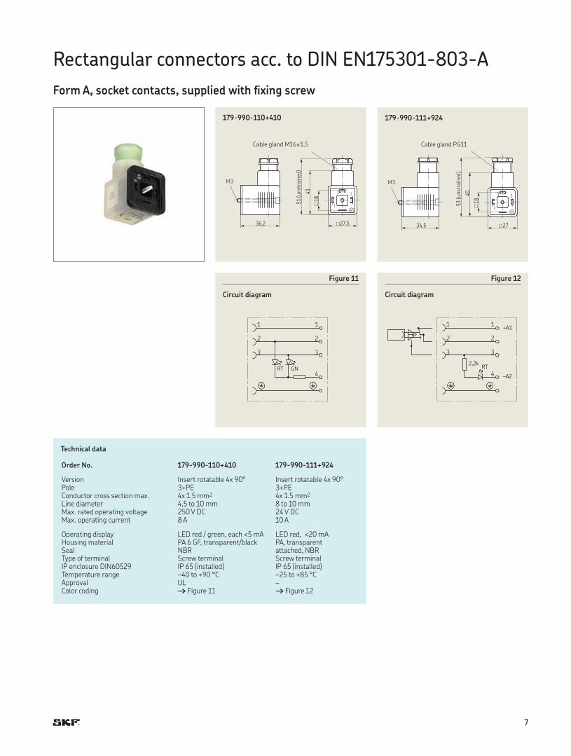
Rectangular connectors acc. to DIN EN--A
Form A, socket contacts, supplied with fixing screw
27,536,2
51
41
18
3 2
1
--+
Technical data
Order No. --+ --+
Version Insert rotatable x ° Insert rotatable x °Pole +PE +PE Conductor cross section max. x . mm x . mm Line diameter , to mm to mmMax. rated operating voltage V DC V DCMax. operating current A A
Operating display LED red / green, each < mA LED red, < mAHousing material PA GF, transparent/black PA, transparent Seal NBR attached, NBRType of terminal Screw terminal Screw terminalIP enclosure DIN IP (installed) IP (installed)Temperature range – to + °C – to + °C Approval UL –Color coding † Figure † Figure
1 1
2 2
3 3
4RT GN
Figure
Circuit diagram
1 1
2 2
3 3
4
RT2,2k
+A1
–A2
Figure
Circuit diagram
2734,5
53
40
18
3 2
1
--+
Cable gland M×,
(un
stra
ined
)
M
Cable gland PG
(un
stra
ined
)
M
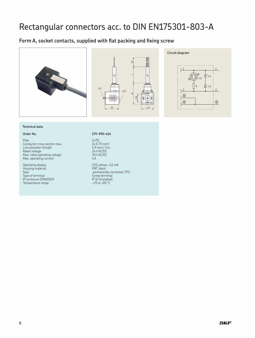
Rectangular connectors acc. to DIN EN--A
Form A, socket contacts, supplied with flat packing and fixing screw
27
2
1
30
45
50
L
18
Technical data
Order No. --
Pole +PE Conductor cross section max. x . mm Line diameter /length . mm / mRated voltage V AC/DCMax. rated operating voltage V AC/DCMax. operating current A
Operating display LED yellow, < mAHousing material PBT, black Seal permanently connected, TPUType of terminal Screw terminalIP enclosure DIN IP (installed)Temperature range – to + °C
1 1
2 2
R
V1V2
V3
Circuit diagram
MLED
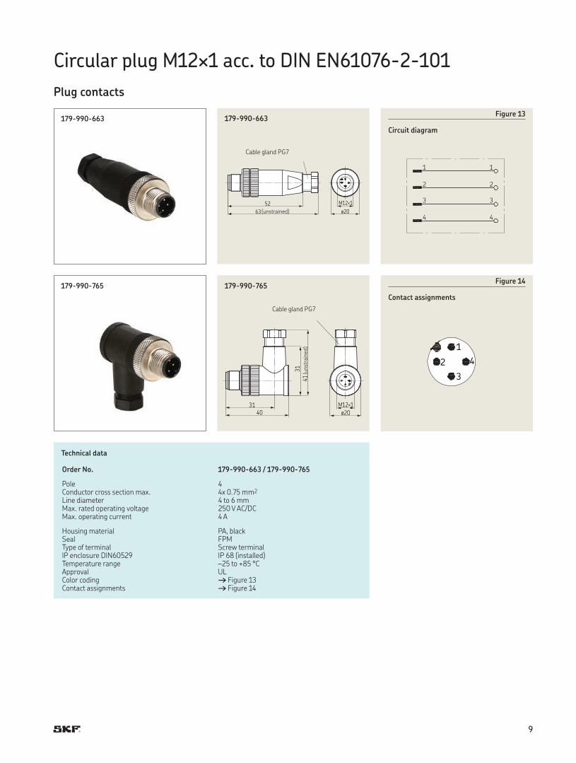
Circular plug M× acc. to DIN EN--
Plug contacts
--
ø20
M12×152
63
--
Technical data
Order No. -- / --
Pole Conductor cross section max. x . mm Line diameter to mm Max. rated operating voltage V AC/DC Max. operating current A
Housing material PA, black Seal FPMType of terminal Screw terminal IP enclosure DIN IP (installed) Temperature range – to + °C Approval ULColor coding † Figure Contact assignments † Figure
--
ø20
M12×131
40
31
41
--
1 1
2 2
3 3
4 4
Figure
Circuit diagram
2
1
3
4
Figure
Contact assignments
Cable gland PG
Cable gland PG
(unstrained)
(un
stra
ined
)
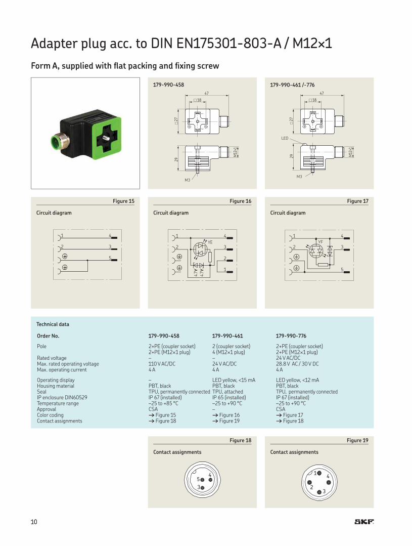
Adapter plug acc. to DIN EN--A / M×
Form A, supplied with flat packing and fixing screw
29
M12×1
21
27
47
18
--
Technical data
Order No. -- -- --
Pole +PE (coupler socket)+PE (M× plug)
(coupler socket) (M× plug)
+PE (coupler socket)+PE (M× plug)
Rated voltage – – V AC/DCMax. rated operating voltage V AC/DC V AC/DC . V AC / V DCMax. operating current A A A
Operating display – LED yellow, < mA LED yellow, < mAHousing material PBT, black PBT, black PBT, black Seal TPU, permanently connected TPU, attached TPU, permanently connectedIP enclosure DIN IP (installed) IP (installed) IP (installed)Temperature range – to + °C – to + °C – to + °C Approval CSA – CSAColor coding † Figure † Figure † Figure Contact assignments † Figure † Figure † Figure
YE
1 4
2 3
2
1
47V
47V
Figure
Circuit diagram
YE
1 4
2 3
5
Figure
Circuit diagram
29 M12×1
21
27
47
18
-- /-
MM
1 4
2 3
5
Figure
Circuit diagram
5
3
4
Figure
Contact assignments
1
23
4
Figure
Contact assignments
LED

!Important information on product usageSKF and Lincoln lubrication systems or their components are not
approved for use with gases, liquefied gases, pressurized gases in solution and fluids with a vapor pressure exceeding normal atmospheric pressure (1 013 mbar) by more than 0,5 bar at their maximum permissible temperature.
skf.com | skf.com/lubrication
® SKF is a registered trademark of the SKF Group.
© SKF Group The contents of this publication are the copyright of the publisher and may not be reproduced (even extracts) unless prior written permission is granted. Every care has been taken to ensure the accuracy of the information contained in this publication but no liability can be accepted for any loss or damage whether direct, indirect or consequential arising out of the use of the information contained herein.
PUB LS/P EN · --DE · January