soft computing and modeling approaches for … computing and modeling approaches for complex ......
TRANSCRIPT

Soft Computing and Modeling Approaches for Complex Systems
and Signal Processing
Research in Computing Science
Series Editorial Board
Editors-in-Chief:
Grigori Sidorov (Mexico) Gerhard Ritter (USA)
Jean Serra (France)
Ulises Cortés (Spain)
Associate Editors:
Jesús Angulo (France)
Jihad El-Sana (Israel) Alexander Gelbukh (Mexico)
Ioannis Kakadiaris (USA)
Petros Maragos (Greece) Julian Padget (UK)
Mateo Valero (Spain)
Editorial Coordination: María Fernanda Rios Zacarias
Research in Computing Science es una publicación trimestral, de circulación internacional, editada por el
Centro de Investigación en Computación del IPN, para dar a conocer los avances de investigación científica
y desarrollo tecnológico de la comunidad científica internacional. Volumen 103, Octubre 2015. Tiraje: 500
ejemplares. Certificado de Reserva de Derechos al Uso Exclusivo del Título No. : 04-2005-121611550100-
102, expedido por el Instituto Nacional de Derecho de Autor. Certificado de Licitud de Título No. 12897,
Certificado de licitud de Contenido No. 10470, expedidos por la Comisión Calificadora de Publicaciones y
Revistas Ilustradas. El contenido de los artículos es responsabilidad exclusiva de sus respectivos autores.
Queda prohibida la reproducción total o parcial, por cualquier medio, sin el permiso expreso del editor,
excepto para uso personal o de estudio haciendo cita explícita en la primera página de cada documento.
Impreso en la Ciudad de México, en los Talleres Gráficos del IPN – Dirección de Publicaciones, Tres
Guerras 27, Centro Histórico, México, D.F. Distribuida por el Centro de Investigación en Computación,
Av. Juan de Dios Bátiz S/N, Esq. Av. Miguel Othón de Mendizábal, Col. Nueva Industrial Vallejo, C.P.
07738, México, D.F. Tel. 57 29 60 00, ext. 56571.
Editor responsable: Grigori Sidorov, RFC SIGR651028L69
Research in Computing Science is published by the Center for Computing Research of IPN. Volume
103, October 2015. Printing 500. The authors are responsible for the contents of their articles. All rights
reserved. No part of this publication may be reproduced, stored in a retrieval system, or transmitted, in any
form or by any means, electronic, mechanical, photocopying, recording or otherwise, without prior
permission of Centre for Computing Research. Printed in Mexico City, in the IPN Graphic Workshop –
Publication Office.
Volume 103

Soft Computing and Modeling Approaches for
Complex Systems andSignal Processing
Sabu M. ThampiChristian Callegari
(eds.)
Instituto Politécnico Nacional, Centro de Investigación en Computación
México 2015

ISSN: 1870-4069
Copyright © Instituto Politécnico Nacional 2015
Instituto Politécnico Nacional (IPN)
Centro de Investigación en Computación (CIC)
Av. Juan de Dios Bátiz s/n esq. M. Othón de Mendizábal
Unidad Profesional “Adolfo López Mateos”, Zacatenco
07738, México D.F., México
http://www.rcs.cic.ipn.mx
http://www.ipn.mx
http://www.cic.ipn.mx
The editors and the publisher of this journal have made their best effort in
preparing this special issue, but make no warranty of any kind, expressed or
implied, with regard to the information contained in this volume.
All rights reserved. No part of this publication may be reproduced, stored on a
retrieval system or transmitted, in any form or by any means, including
electronic, mechanical, photocopying, recording, or otherwise, without prior
permission of the Instituto Politécnico Nacional, except for personal or
classroom use provided that copies bear the full citation notice provided on
the first page of each paper.
Indexed in LATINDEX, DBLP, and Periodica
Printing: 500
Printed in Mexico

Preface
In this issue, we present papers on soft computing and modelling approaches for
complex systems and signal processing. This issue includes nine papers selected after
peer review process. A summary of papers is as follows.
“UML Behavioral Refactoring for the Specification of Complex Software Sys-
tems,” by M.T. Chitra and S. Elizabeth, proposes a generic framework for effective
code generation from UML models which serves as an interexchange format to com-
bine both structural and behavioral constraints of associated system objects to facili-
tate consistent source code generation.
“Accuracy of Artificial Neural Network Models of Software Reliability Growth –A
Survey,” by M. K. Saley and S. Sreedharan, discusses predicting errors of Artificial
Neural Networks-based Software Reliability Growth Models (ANN SRGM). This
survey concludes that ANN SRGM is better than statistical models for reliability pre-
diction.
“Statistical and alignment based methods for comparison of non-coding DNA se-
quences,” by Kouser and L. Rangarajan, proposes few techniques that capture the
information regarding the arrangement of the motifs to assist in the analysis of the
promoter sequences.
“On Rate Adjustment Mechanism for Reliable Multicast Transmission in ForCES,”
by L. Gong, Y. Wang, and C. Li discusses the issues of the reliable multicast rate ad-
justment mechanisms within Forward and Control Element Separation (ForCES), and
proposes a rate adjustment mechanism of control unit. The paper also presents a de-
sign of a congestion feedback mechanism based on the feedback representative set.
“Electronic system for orientation control and obstacle avoidance for underwater
glider without a rudder,” by Y. N. Patil, V. S. Aneesh, M. T. Abhilash, and S. Kadlag,
proposes an approach for achieving better propagation of autonomous underwater
gliders with the help of orientation sensors.
“A New Approach to Adaptive Power Line Interference Removal,” by A. R. Ka-
setwar and S. M. Gulhane, conducts a study on various methods for power line inter-
ference (PLI) removal for biomedical signal processing. Few algorithms are analyzed
for their applications in adaptive power line interference removal.
“Development of Dual-Actuated Stage for Positioning Applications,” by P. Niran-
jan, K. V. S. S. S. S. Sairam, and S. Karinka, presents and validates a model for de-
scribing the nonlinearity of the piezoelectric actuator.
“Concatenated Tabla Sound Synthesis to Help Musicians,” by U. K. Roy proposes
a scheme to synthesize pre-recorded tabla sounds to help musicians.
“Chronological Advancement in Compiler Design: A Review”, by A. Verma and
N. Bakshi carries out a brief survey on key properties of compiler courses in some
universities.
Sabu M. Thampi
Associate Professor, School of CS/IT
Indian Institute of Information Technology and Management - Kerala (IIITM-K)
Technopark Campus, Trivandrum-695581, Kerala, India
E-mail: [email protected]
5 Research in Computing Science 103 (2015)

Christian Callegari
TLC NETworks research GRoup
Dept. of Information Engineering
University of Pisa, Italy
E-mail: [email protected]
Guest Editors
6Research in Computing Science 103 (2015)

Table of Contents Page
On Rate Adjustment Mechanism for Reliable Multicast Transmission
in ForCES .................................................................................................................... 9
Liang Gong, Yining Wang, Chuanhuang Li
Statistical and Alignment Based Methods for Comparison of Non-Coding
DNA Sequences ......................................................................................................... 21
Kouser, Lalitha Rangarajan
Concatenated Tabla Sound Synthesis to Help Musicians .......................................... 29
Uttam Kumar Roy
A New Approach to Adaptive Power Line Interference Removal............................. 41
Abhay R. Kasetwar, Sanjay M. Gulhane
UML Behavioral Refactoring for the Specification of Complex Software
Systems ...................................................................................................................... 51
M.T. Chitra, Sherly Elizabeth
Electronic System for Orientation Control and Obstacle Avoidance
for Underwater Glider without a Rudder ................................................................... 69
Yuvraj N. Patil, V. S. Aneesh, M. T. Abhilash, Swati Kadlag
Accuracy of Artificial Neural Network Models of Software Reliability
Growth – A Survey .................................................................................................... 83
M. K. Saley, Sasikumaran Sreedharan
Development of Dual-Actuated Stage for Positioning Applications ......................... 93
Prabha Niranjan, K. V. S. S. S. S. Sairam, Shashikantha Karinka
Chronological Advancement in Compiler Design: A Review ................................... 99
Amit Verma, Nikita Bakshi
7 Research in Computing Science 103 (2015)


On Rate Adjustment Mechanism for Reliable MulticastTransmission in ForCES
Liang Gong1, Yining Wang2, and Chuanhuang Li1
1College of Information & Electronic Engineering Zhejiang Gongshang University,Hangzhou, Zhejiang Province, China
[email protected], [email protected] of Computer Science and Technology, Zhejiang University,
Hangzhou, Zhejiang Province, [email protected]
Abstract. In the specific environment for reliable multicast transmission ofForCES protocol messages, this paper firstly analyzed the congestion control diffi-culties and problems in the process of the reliable multicast transmission, and thendesigned and proposed a reliable multicast rate adjustment mechanism whichmeets the architectural requirements of ForCES routers. Test results also show thatthe mechanism basically meets the relevant performance requirements.
Keywords: ForCES; Reliable Multicast; Congestion Control; Rate Adjustment.
1 Introduction
ForCES (Forward and Control Element Separation) Working Group [1] is one of IETFworking groups in the field of routing, which has committed to the research and devel-opment of open programmable router architecture and protocol since its inception.ForCES router architecture is composed by the control unit (CE) and the forwardingunit (FE) in the structure, and CE and FE can transmit information through the ForCESprotocol.
Within ForCES routers, one CE needs multiple FEs to transmit protocol messages.Compared with multiple TCP unicasts, IP multicast can save bandwidth between ForCEStransport mapping layers. Because the protocol message is only copied at the branchingnode of the multicast tree, it avoids CE producing redundant protocol message packets,and reduces the load of the CE port and improves the transmission efficiency. However,as the multicast transmission is based on UDP protocols, CE transmits protocol messagesat a fixed rate, if the network environment is deteriorated, the sending rate of CE cannotbe adjusted to the protocol messages flow, which may lead to a further deterioration ofthe network environment, or even a collapse. There are already a number of multicastcongestion control protocols, such as Pragmatic General Multicast Congestion Control(PGMCC) [2], TCP-friendly Multicast Congestion Control (TFMCC) [3], Receiver-driven Layered Multicast (RLM) [4], and other agreements and so on.
9 Research in Computing Science 103 (2015)pp. 9–19; rec. 2015-06-03; acc. 2015-06-20

Currently, there are mainly two types of reliable multicast transport protocols whichare based on acknowledgment (ACK) or based on negative acknowledgment (NACK).Reliable multicast protocol messages within ForCES adopt the mechanism of errordetection and recovery, which is based on the negative acknowledgment (NACK), andit can better ensure the reliable transmission of multicast protocol messages.
In order to ensure the friendly fairness to TCP, Ma et al. [5] proposed Fair ActiveCongestion Control (FACC), which starts with a single rate by the receiver, and takesa transmission rate as congestion control parameters. In order to increase the robust-ness and adaptivity of the algorithm, the protocol took congestion parameter conver-gence strategy to redesign the filtering algorithm of the congestion control parameter.To eliminate the phenomenon of “slowest priority”, Zhai, Wu and Gu [6] proposed twomechanisms that are Composite Multicast Congestion Control (CMC) and LayeredMulticast (LM) Congestion Control by the Particle Swarm Optimization (PSO) (LM-PSO). Both of these mechanisms do not use a single-rate congestion control algorithm,but use an algorithm where each layer of the Layered Multicast adjusts the transmis-sion rate dynamically.
In this paper, in view of the research of the Multicast Congestion ControlMechanisms, we have taken the detailed analysis and research about the issues of thereliable multicast rate adjustment mechanisms within ForCES, and adopted theWireshark capturing software to test the traffic conditions of the CE port during theprocess of protocol messages reliable multicast. What is more, by drawing a graph ofthroughput situations of data packets, we analyzed the problem of reliable multicastabout fairness and heterogeneity within ForCES.
2 Main Problem of the Reliable Multicast Rate AdjustmentMechanism within ForCES Routers
Similar to the TCP congestion control, currently the ForCES routing channel protocolmessage is based on multicast on IP layer. The reliable multicast protocol messagewithin ForCES adopts the point-to-point rate adjustment mechanism. Therefore, pro-tocol messages reliable multicast rate adjustment mechanism within ForCES can learnfrom the TCP congestion control mechanism absolutely, research from the regulatorparameters, feedback mechanisms, and other aspects of rate regulation algorithm.However, considering the environment of reliable multicast is much more complexthan that of unicast, TCP congestion control mechanisms cannot be applied simply onreliable multicast, and the specific scenarios of reliable multicast within ForCES mustbe combined to carry out a detailed analysis and design for each point.
Another issue of the reliable multicast rate adjustment mechanism within ForCESthat must be solved is fairness, which appears much more important in multicast envi-ronment. For reliable multicast, the fairness of congestion control mechanism has twomeanings. On the one hand, the fairness is that, the protocol message stream that trans-mits in the form of TCP shares the network bandwidth with a reliable multicast stream.On the other hand, the fairness is that each FE of multicast receivers is fair. For exam-ple, the sending rate of CE cannot be decided by the FE which has the worst networkcondition, and this is obviously unfair for other FE ports. Therefore, the rate adjustment
10
Liang Gong, Yining Wang, Chuanhuang Li
Research in Computing Science 103 (2015)

mechanism of reliable multicast protocol messages within ForCES must satisfy theheterogeneity between each FE. In order to achieve intra protocol fairness, and toensure the sufficient and effective use of the network bandwidth of ForCES transportmapping layer, all of these problems should be considered and designed in the researchof this paper.
3 Analysis of Concrete Problems of Reliable Multicast RateAdjustment Mechanism within ForCES Routers
3.1 Preferences of Reliable Multicast Rate Regulation
The CE sender of the reliable multicast within ForCES relays on the hardware plat-form, the transmission rate of which is impacted by the processor hardware itself. Ifadopting the rate adjustment mechanism based on the sending frequency, the networkprocessor of CE should be made certain modifications on the kernel, and every rateadjustment process should be switched between the kernel space and the user spaceconstantly, which will increase the expense of time, and cannot meet the real-timerequirement of the reliable multicast rate adjustment mechanism. Therefore, the reli-able multicast within ForCES adopts a rate adjustment based on a window parameter.In order to adjust the rate, and to achieve the rate adjustment mechanism by the soft-ware, and to avoid modifying hardware, CE can adjust the size of the sending windowaccording to the feedback messages sent by FE, so that the whole rate adjustmentmechanism can have greater flexibility and feasibility.
Referring to TCP congestion control mechanisms, during the process of reliablemulticast within ForCES, the size of a sending window maintained by CE is set as W0,and then simulating the AIMD mechanism to adjust the size of the sending window.For reliable multicast — a one-to-many model in transmission, CE cannot grasp thenetwork congestion of FE timely and accurately. When the size of sending windowincreases in an additive way, it will become too large and cause a network congestion.As this result, we cannot introduce TCP congestion control mechanisms to the multi-cast environment simply.
We use the method that setting a sending threshold denoted as W’ at CE, which isused to adjust the size of the sending window. The sending threshold is the maximumsize of the sending window at CE during the process of reliable multicast, that is to say,when the size of the sending window has reached the threshold, namely W’, if we con-tinue to increase the size of the sending window, the efficiency of multicast will not beimproved. So a sending threshold can be set according to the size of the measured val-ues for each multicast test or empirical values. Thus, the adjustment parameter for CEshould be set between the sending window and the threshold, the sending window rep-resents the size of each multicast initialization process, namely the size of the mini-mum window. If the size of the sending window is less than this value, FE may receivemulticast messages abnormally, which will waste the multicast network bandwidth, sothat the normal performance of ForCES routers cannot be guaranteed.
In conclusion, the parameter selection of the reliable multicast rate adjustmentwithin ForCES bases on the following principles: the initial sending window size ofCE, denoted as W0. When W0 is lower than the available network bandwidth, denoted
11
On Rate Adjustment Mechanism for Reliable Multicast Transmission in ForCES
Research in Computing Science 103 (2015)

as W1, increases the size of sending window rapidly; when W0 is between W1 and W′,increases the size of sending window slowly to avoid the network congestion; when thenetwork is congested, reduces the size of the sending window, but when W0 is betweenW1 and W′, decreases slowly to avoid the rate oscillation.
3.2 Fairness Problem of Reliable Multicast Transmission
Among reliable multicast protocols within ForCES, the control protocol message sentin the form of multicast competes with the control protocol message within TML in thebandwidth in the rigid way. When the network environment becomes deterioration, thecontrol protocol message flow transmitted in the form of TCP will reduce the sendingrate according to the AIMD mechanism, but the multicast protocol message flow willcontinue being transmitted in the original rate, or even a greater rate. Because of thelack of the corresponding rate adjustment mechanism, it will lead to the collapse of net-work bandwidth. Therefore, in order to achieve the fairness of TCP, a window mecha-nism similar to TCP’s should be taken, but the AIMD window adjustment mechanismof TCP has a great jitter [7], which is not conducive to transmitting the multicast pro-tocol message. So the AIMD mechanism cannot be applied simply in the multicastenvironment within ForCES. In order to get an ideal control curve of the sending rate,we should improve the AIMD mechanism, for example, we can add a series of adjust-ment rules based on the history records to make it smoother.
In the curve of the TCP AIMD mechanism, the increasing factor is set as b, the mul-tiplicative factor is set as a, the size of the sending window is a time function whosefeedback time interval is set as t, during the cycle of the sending window, the functionis denoted as follow:
(1)
Herein, W0 is the initial value of the sender congestion window, t0 is the initial time,t is an integer multiple of the feedback time which is also called RTT, namely, t =n*RTT (n = 0,1,…), so the curve is discrete. However, in order to facilitate the analy-sis, ignoring the effect of timeout and retransmission during the practical transmission,the discrete curve can be simplified as a continuous curve.
From Equation (1), the control curve of AIMD mechanism under the congestioncondition obeys the exponential function curve with a as its base, when t is largeenough, the size of the window is close to 0, but under the non-congestion conditionsit obeys the linear function curve with b as its slope.
According to above analysis, the exponential curve of AIMD mechanism declinesmuch more rapidly at first, when the value is close to the lower limit, it declines slower,the characteristic of which is more appropriate for the protocol message multicasttransmission within ForCES. Considering that, during the protocol message multicasttransmission process, the initial sending window of CE is denoted as W0, the sendingwindow function of CE under the congestion condition is adjusted as:
(2)W t W a W( ) * .= +0 0
W t b t t bW a at
( ) .*( )*={ − >
< <0
00
0 1
12
Liang Gong, Yining Wang, Chuanhuang Li
Research in Computing Science 103 (2015)
At the sending window adjusting algorithm of CE, we adopt the multiplicativedecrease method under the congestion condition:
(3)
In order to be friendly to TCP, we adopt the method which uses a maximum valueto limit the additive increase under the non-congestion conditions:
(4)
Under this window adjustment algorithm, the curve of the transmission rate is lin-ear increasing, and will stop at the sending threshold, denoted as W′. As a result, it can-not achieve the initial requirements. Therefore, the rising amplitude of the additiveincreasing function curve changes from the constant to the variable, the rising ampli-tude of which is related to the difference between its current value and sending thresh-old. So we can design as follow:
(5)
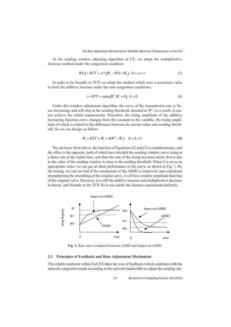
We can know from above, the function of Equations (5) and (3) is complementary, andthe effect is the opposite, both of which have decided the sending window curve rising ata faster rate at the initial time, and then the rate of the rising becomes much slower dueto the value of the sending window is close to the sending threshold. When b is set as anappropriate value, we can get an ideal performance of the curve, as shown in Fig. 1. Bythe testing, we can see that if the mechanism of the AIMD is improved, and consideredstrengthening the smoothing of the original curve, it will have smaller amplitude than thatof the original curve. However, it is still the additive increase and multiplicative decreasein theory, and friendly to the TCP. So it can satisfy the fairness requirement perfectly.
W RTT W b W W bt t t+ = + ′ − < <( ) .0 1
t RTT W W b bt+ = ′ +{ } >min , .0
W t RTT a W W W at( ) * .+ = − +( ) < <0 0 10
W’
W1
W0
Sending Rate
0 time 0 time
W0
W1
W0
Improved AIMD
AIMD
Improved AIMD
AIMD
Fig. 1. Rate curve compared between AIMD and improved AIMD.
3.3 Principles of Feedback and Rate Adjustment Mechanism
The reliable multicast within ForCES takes the way of feedback (which combines with thenetwork congestion trends according to the network bandwidth) to adjust the sending rate.
13
On Rate Adjustment Mechanism for Reliable Multicast Transmission in ForCES
Research in Computing Science 103 (2015)

The principles which should be adopted during the reliable multicast within ForCESare as follows:
1. FE makes the congestion judgment according to the average packet-dropout inter-val packets during each multicast process, and sends feedback to CE;
2. CE makes the judgment about the trend of the network bandwidth by grasping thenetwork congestion of FE and combining the current sending rate with the histori-cal rate during the last multicast, and adjusts the sending rate according to thechange of the network bandwidth;
3. CE updates the history records of multicast after every sending rate adjustment andkeep the history records, in preparation for the next sending rate adjustment.
In order to reflect the congestion situation of the current network correctly, we adoptan exponential weighted moving average method for the historical packet-dropout rateto judge the condition of the network congestion.
In order to assist the judgment of the network bandwidth variation trend, the reli-able multicast within ForCES needs keeping a group of history records, denoted as H= {Sc,Snc}, wherein, Sc stands for the control status of the sending rate under the recentcondition of the multicast congestion, and Snc stands for the control status of the send-ing rate under the recent condition of the non-congestion. At the beginning of the reli-able multicast, the trends of the network bandwidth of CE, denoted as B, aredocumented as follows:
B = 0: The available network bandwidth is stable;B = 1: The available network bandwidth is increasing;B = –1: The available network bandwidth is decreasing.
The trend of network bandwidth is judged by the rules which are as follows:
1. At beginning, the size of the sending window at CE is denoted as W0, if receivingthe congestion feedback from FE during the multicast transmission process, and thesize of the current sending window, denoted as W, is less than the value of Sc in thehistory of H, the network bandwidth will be considered decreasing, so B = –1;
2. If not receiving the congestion feedback from FE during the multicast transmissionprocess, and the size of the current sending window, denoted as W, is larger than thevalue of Snc in the history of H, the network bandwidth will be considered increas-ing, so B = 1;
3. If the size of the current sending window of CE, denoted as W, is between Sc andSnc, or does not meet the two necessary conditions of above two at the same time,the network will be considered stable, so B = 0.
As a result, the reliable multicast rate adjustment algorithm within ForCES, whichis based on the sending window, is as follow:
1. If the network bandwidth variation trend is identified as B = –1, updating the sizeof the sending window according to Equation (5);
14
Liang Gong, Yining Wang, Chuanhuang Li
Research in Computing Science 103 (2015)
2. If the network bandwidth variation trend is identified as B = 1, updating the size ofthe sending window according to Equation (3);
3. If the network bandwidth variation trend identified as B = 0, updating the size of thesending window according to Equation(6);
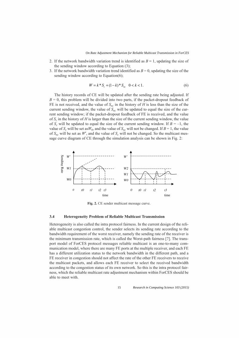
(6)
The history records of CE will be updated after the sending rate being adjusted. IfB = 0, this problem will be divided into two parts, if the packet-dropout feedback ofFE is not received, and the value of Snc in the history of H is less than the size of thecurrent sending window, the value of Snc will be updated to equal the size of the cur-rent sending window; if the packet-dropout feedback of FE is received, and the valueof Sc in the history of H is larger than the size of the current sending window, the valueof Sc will be updated to equal the size of the current sending window. If B = –1, thevalue of Sc will be set asW0, and the value of Snc will not be changed. If B = 1, the valueof Snc will be set as W′, and the value of Sc will not be changed. So the multicast mes-sage curve diagram of CE through the simulation analysis can be shown in Fig. 2:
W k S k S kc nc= + − < <* ( )* .1 0 1
t0 t1 t2 t3
W’ W1
W0
0 t0 t1 t2 t3
W’ W2
W1
W0
0
time
SendingR
ate
time
Fig. 2. CE sender multicast message curve.
3.4 Heterogeneity Problem of Reliable Multicast Transmission
Heterogeneity is also called the intra protocol fairness. In the current design of the reli-able multicast congestion control, the sender selects its sending rate according to thebandwidth requirement of the worst receiver, namely the sending rate of the receiver isthe minimum transmission rate, which is called the Worst-path fairness [7]. The trans-port model of ForCES protocol messages reliable multicast is an one-to-many com-munication model, where there are many FE ports at the multiple receiver, and each FEhas a different utilization status to the network bandwidth in the different path, and aFE receiver in congestion should not affect the rate of the other FE receivers to receivethe multicast packets, and allows each FE receiver to select the received bandwidthaccording to the congestion status of its own network. So this is the intra protocol fair-ness, which the reliable multicast rate adjustment mechanism within ForCES should beable to meet with.
15
On Rate Adjustment Mechanism for Reliable Multicast Transmission in ForCES
Research in Computing Science 103 (2015)

The rate regulation feedback mechanism of the protocol message multicastwithin ForCES adopts the mechanism which selects a set of worse FE receiversto represent a multicast congestion conditions. During the reliable multicastprocess of intra protocol messages, initially, CE sends the Session Messages to FE,and FE does not calculate the packet-dropout at the same time, so FE does not sendthe feedback message. When the second session message arrives, every FE sendsthe ACK feedback packets which include the packet-dropout during the last multi-cast process and the RTT timestamps. Among them, because the transmissionof session messages between CE and FE is the one-way, the session message istransmitted by TCP. But, each FE forwarding element may serve as an importantrole in the architecture of ForCES router, as a result, each FE must be ensuredreceiving protocol messages reliably. However, because the function of the ACKfeedback message is to feedback the congestion status to CE, the feedback mes-sage is transmitted by UDP. As CE has the overall grasp of the receiving capacityand throughput of each FE to coordinate the rate adjustment and avoid the conges-tion, losing the ACK feedback message is allowed under the premise of satisfyingcertain QoS.
We select a group of ACK feedback messages from the session packets dynamicallyevery time, which is required not only to represent the bandwidth utilization andthroughput under poor reception conditions of FE, but not to cause an intra protocol tobe unfair because of the excessive inhibition of the sending rate of CE. As shown inFig. 3:
R~S FE
CE
Fig. 3. Feedback set of multicast within ForCES.
4 Performance Testing
4.1 Fairness Testing of Reliable Multicast Transmission
Operating the reliable multicast testing procedures at FE and CE separately, the CE testprogram joins a multicast group through the IGMP protocol, of which the ID is0xC0000000, the IP address is 233.4.4.4 and the members include three hosts, whoseIP addresses are 10.20.0.59, 10.20.0.190, 10.20.0.229 respectively, and sends 1000multicast protocol messages to 0xC0000000. On the other hand, setting the parameters
16
Liang Gong, Yining Wang, Chuanhuang Li
Research in Computing Science 103 (2015)
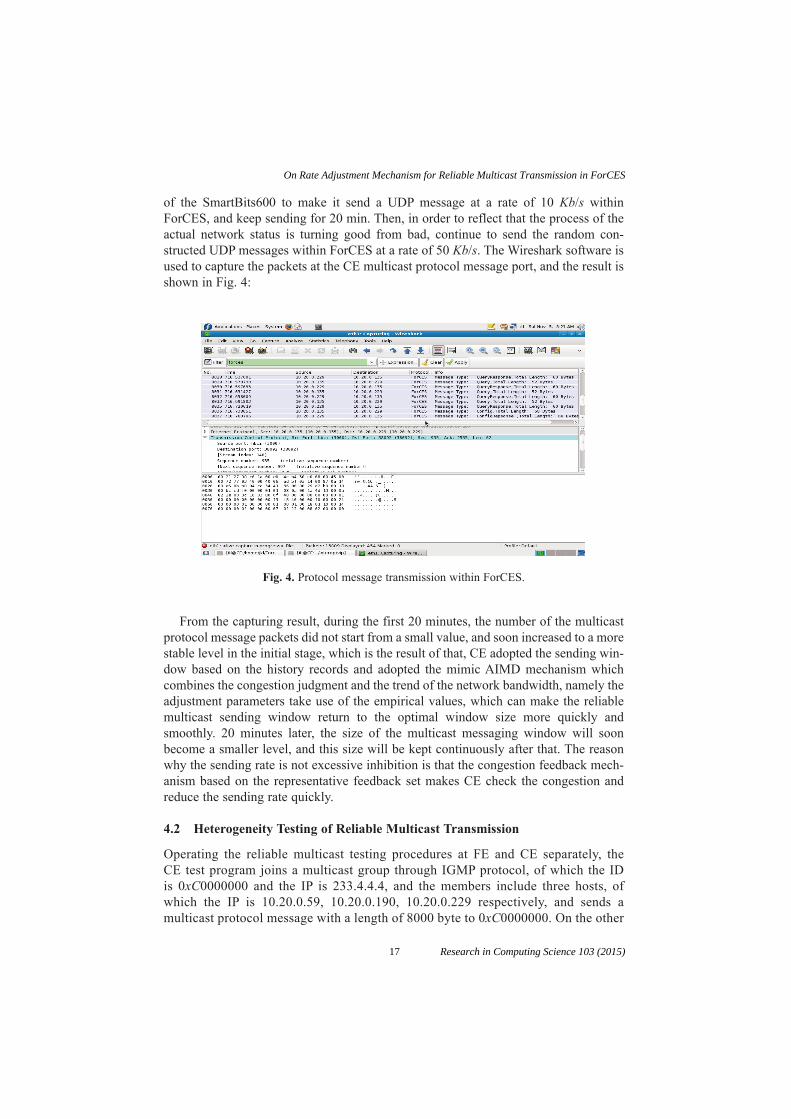
of the SmartBits600 to make it send a UDP message at a rate of 10 Kb/s withinForCES, and keep sending for 20 min. Then, in order to reflect that the process of theactual network status is turning good from bad, continue to send the random con-structed UDP messages within ForCES at a rate of 50 Kb/s. The Wireshark software isused to capture the packets at the CE multicast protocol message port, and the result isshown in Fig. 4:
Fig. 4. Protocol message transmission within ForCES.
From the capturing result, during the first 20 minutes, the number of the multicastprotocol message packets did not start from a small value, and soon increased to a morestable level in the initial stage, which is the result of that, CE adopted the sending win-dow based on the history records and adopted the mimic AIMD mechanism whichcombines the congestion judgment and the trend of the network bandwidth, namely theadjustment parameters take use of the empirical values, which can make the reliablemulticast sending window return to the optimal window size more quickly andsmoothly. 20 minutes later, the size of the multicast messaging window will soonbecome a smaller level, and this size will be kept continuously after that. The reasonwhy the sending rate is not excessive inhibition is that the congestion feedback mech-anism based on the representative feedback set makes CE check the congestion andreduce the sending rate quickly.
4.2 Heterogeneity Testing of Reliable Multicast Transmission
Operating the reliable multicast testing procedures at FE and CE separately, theCE test program joins a multicast group through IGMP protocol, of which the IDis 0xC0000000 and the IP is 233.4.4.4, and the members include three hosts, ofwhich the IP is 10.20.0.59, 10.20.0.190, 10.20.0.229 respectively, and sends amulticast protocol message with a length of 8000 byte to 0xC0000000. On the other
17
On Rate Adjustment Mechanism for Reliable Multicast Transmission in ForCES
Research in Computing Science 103 (2015)

hand, the UDP message constructed by SmartBits600 transports at the rate of200 Kb/s, to simulate the actual network environment, the send status is shown inFig. 5:
Fig. 5. Feedback situation of the feedback represents.
From Fig. 5, during the multicast process, FE sent session messages in the form ofUDP to respond to ACK messages periodically; the periodic time was set nearly as longas the cycle timer of the session message, but the feedback ID had a slightly difference.As a conclusion, the feedback mechanism based on the feedback representative set hasa more sensitive feedback characteristic and a less feedback oscillation than thosebased on the worst receiver.
5 Conclusion
On the basis of current research status of multicast congestion control, because of thelack of the rate regulatory mechanisms within the original ForCES, this paper puts for-ward a kind of rate adjustment mechanism of CE based on an improved AIMD mech-anism, which meets the demands of fairness within ForCES. Through the research ofthe heterogeneity of the receiving port, this paper also designs a congestion feedbackmechanism based on the feedback representative set and this mechanism can also meetthe intra protocol fairness better.
Acknowledgments
This work was supported in part by a grant from the National Basic Research Programof China (973 Program) (No.2012CB315902), the National Natural Science
18
Liang Gong, Yining Wang, Chuanhuang Li
Research in Computing Science 103 (2015)

Foundation of China (No.61402408,61379120,61170215), Zhejiang Leading Team ofScience and Technology Innovation (No.2011R50010-03, 2011R50010-12,2011R50010-20), Zhejiang Provincial Key Laboratory of New Network Standards andTechnologies (NNST) (No.2013E10012).
References
1. Halpern, J., Salim, J.H.: “Forwarding and Control Element Separation (ForCES) ForwardingElement Model”, RFC 5812, Mar. 2010, http: //www.ietf.org/html.charters/forces-charter.html
2. Rizzo, L.: PGMCC: A TCP-friendly Single-rate Multicast Congestion Control Scheme[C], inProceedings of ACM SIGCOMM, 2000.
3. Fairhurst, K.: “TFMCC Protocol Behaviour in Satellite Multicast with Variable Return PathDelays” IEEE 2006.
4. McCanne, S., Jacobson, V., Vetterli, M.: Receiver-driven Layered Multicast, in: Conferenceproceedings on applications, technologies, architectures, and protocols for computer com-munications, vol. 26, ACM, SIGCOMM, 1996, pp. 117–130.
5. Ma, H., Meng, X., Ma, Z., Li, J.: Layered Multicast Congestion Control by Particle SwarmOptimization in Heterogeneous Environment [J]. The Journal of China Universities of Postsand Telecommunications, 2011, 18(3):85–91.
6. Zhai, M., Wu, G., Gu, G.: Internet Congestion Control and Reliable Multi-point DeliveryProgress [J]. Computer Research and Development, 2000, Vol. 37, No. 1.
7. Bhattacharyya, S., Towsley, D., Kurose, J.: The Loss Path Multiplicity Problem in MulticastCongestion Control [C]. Proceedings of IEEE INFOCOM, New York, March 1999, vo1. 2,pp. 856–863.
8. Xie, F., Feng, G.*, Siew, C.K.: Study on Nominee Selection for Multicast Congestion Control[J]. Computer Communications 29(2006) 1458–1469.
19
On Rate Adjustment Mechanism for Reliable Multicast Transmission in ForCES
Research in Computing Science 103 (2015)

Statistical and Alignment Based Methods for Comparisonof Non-Coding DNA Sequences
Kouser and Lalitha Rangarajan*
DoS in Computer Science, University of Mysore, Mysore, Karnataka, India.*[email protected]
Abstract. Increase in the amount of biological sequence data being generated isdue to the advancement in the sequencing technologies. This has led to an upsurgein the need for methods/techniques that analyze these sequences to make biologi-cal inferences. Promoter sequences are one such biological sequences that play animportant role in the process of gene regulation. These promoter sequences aremade up of motifs arranged/configured in a particular order which is very impor-tant for its functionality. In this work, we propose a few techniques that capture theinformation regarding the arrangement of these motifs. Further this captured infor-mation help in the analysis of the promoter sequences. The methods use the motiffeatures obtained from the Position Specific Motif Matrices (PSMMs) of the pro-moter sequences and then give a dissimilarity measure. Alignment-free as well asalignment based methods are proposed. The experimental results show that thesemethods are quite successful in bringing out the similarity/dissimilarity existingbetween given promoters/promoter sets. The alignment based method also helps inthe process of inferring homology and in the phylogenetic analysis. In general, allthe methods might help biologists in applications like drug target identification,biological pathway analysis and gene expression analysis.
Keywords: Alignment free, Alignment score, Multiple Sequence Alignment,Promoter sequences, Dissimilarity matrix, Sequence comparison.
1 Introduction
With the rapid growth in the generation of large wealth of biological sequence data, mak-ing sense of this huge data is a challenging task. There is an immediate need for goodanalyzing methodologies. These methods/techniques help in the process of extractingmeaningful information from the sequences for better understanding of biomedicalmechanisms [1] and to attempt to solve some specific biological problems. Some recentefforts are focused to identify functions of these non-coding DNA sequences which havesome important function in gene expression analysis, tissue development, phylogeneticanalysis which serves as the motivation to this kind of research work [2].
The analysis of these biological sequences consists of two major steps. Initial stepis alignment which is later followed by analysis. Most of the existing multiplesequence alignment (MSA) works well on coding regions of the genes or the proteins.
21 Research in Computing Science 103 (2015)pp. 21–27; rec. 2015-06-03; acc. 2015-06-20

The MSA algorithms are built using the principles of dynamic programming (Smith-Waterman and Needleman-Wunsch algorithms) [3], hidden markov model [4] andscoring matrices. There are several tools available that work on these concepts to namea few SW-align, Clustal W [3], MUSCLE [5], K align [6], D align [7], T-Coffee [8],M-Coffee [9]. There is a plenty of work on alignment free sequence analysis methodssuch as L-words frequency [10], spaced-word frequency methods [11], relative fre-quencies of dual nucleotides [12] etc. Many methods relating to k-mer/word frequency,substring, information theory and graphical representation are also available. Somesoftwares available for the methods described above include d2Tools [13], AGP [14],Alfy [15] and WNV typer [16].
In this work, we propose methods to analyze promoter sequences which are madeup of repetitive patterns called transcription factor binding sites (TFBS)/motifs. Thepromoter sequences are a part of the non-coding DNA anywhere before the start codonof a gene and the stop codon of the previous gene, which plays an important role in theprocess of gene expression. The data set is obtained from the NCBI database and thePSMM are created using the TFSEARCH tool [17].
2 Materials and Methods
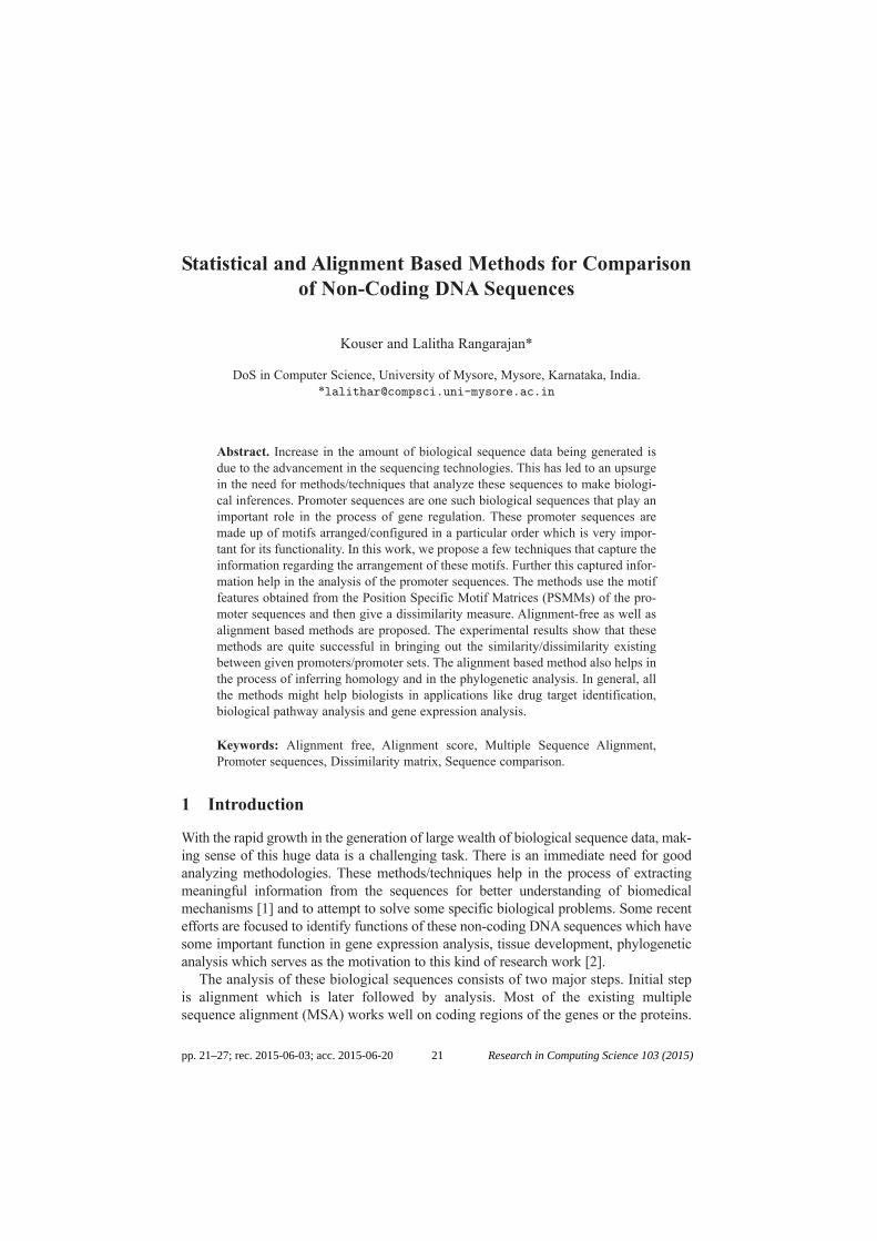
In this section, we describe the working details of our model and the proposed algorithms.Five frequency based methods proposed and one lacunarity algorithm which are all align-ment free sequence comparison methods. Also, we propose one alignment based sequenceanalysis method which makes use of the motif pair feature. There are two datasets used,dataset 1 consisting of promoters of the Pyruvate kinase gene of different organisms anddataset 2 consisting of all the enzymes of the Glycolysis pathway of the organism human.The overall schema and flow of the method is as described in Figure 1. The detaileddescription of obtaining the PSMM for a promoter is presented in [18], [19]. Once thePSMM is obtained, they are given as input to the various methods briefly described below.
2.1 Frequency Based Alignment Free Methods
The frequency distribution gives a measure considering the occurrences of motifs inpromoters in various ways. The detailed description of these frequency based methodsis presented [19], [20]. The output of these methods is a dissimilarity matrix.
2.2 Lacunarity Based Method
The lacunarity algorithm is a multi scaled method that uses box counting across differ-ent scales to obtain the lacunarity values across different scales and then the Euclidiandistance is used to get the dissimilarity between two promoters. This value then goes asan entry into the dissimilarity matrix. The algorithm can be found in detail in [18].
2.3 Alignment Based Method
This method extracts the motif pair based features from the binarized PSMM [21].Later, we compare the count of motif pairs between the promoter sequences to find thesimilarity. The output of alignment is an alignment score.
22
Kouser, Lalitha Rangarajan
Research in Computing Science 103 (2015)
Fig. 1. Overall schema and flow of the methods.
3 Results and Discussion
All the methods described are quite successful in bringing out the similarity betweenorganisms that are known to belong to the same family. The dissimilarity is very lowfor similar organisms and high otherwise. The results of the frequency based methodand the alignment based methods on dataset 1 are presented in Tables 1 and 2. Also,the result of lacunarity analysis is given in Table 3. Results of the frequency basedmethod and the alignment based methods on dataset 2 are presented in Tables 4 and 5.However some cases where some unusual results were obtained are highlighted in therespective dissimilarity matrices.
Table 1. Dissimilarity matrix of frequency based method on dataset 1.(Organisms: 1. Homo sapien (human), 2. Gorilla gorilla (gorilla), 3.Macaca mulatta
(rhesus monkey), 4. Bos taurus (cattle), 5.Felis catus (cat), 6.Pan troglodytes (chimpanzee)7. Canis lupus (dog), 8.Rattus norvegicus (rat), 9.Drosophila melanogaster (fruit fly) and
10. Pseudomonas aeruginosa (bacterium)).
Human Gorilla Monkey Cattle Cat Chimpanzee Dog Rat Fruit Fly Bacteria
Human 0 299 1629 903 1411 1378 1439 451 1531 1346Gorilla 299 0 890 256 568 581 604 266 796 587Monkey 1629 890 0 400 500 283 488 1608 306 629Cattle 903 256 400 0 300 213 256 820 256 369Cat 1411 568 500 300 0 267 198 1302 480 125Chimpanzee 1378 581 283 213 267 0 169 1263 101 298Dog 1439 604 488 256 198 169 0 1310 262 173Rat 451 266 1608 820 1302 1263 1310 0 1606 1275Fruit fly 1531 796 306 256 480 101 262 1606 0 497Bacteria 1346 587 629 369 125 298 173 1275 497 0
23
Statistical and Alignment Based Methods for Comparison of Non-Coding DNA Sequences
Research in Computing Science 103 (2015)

Table 2. Alignment scores of enzyme pyruvate kinase in different organisms.(Organisms: 1. Homo sapien (human), 2. Gorilla gorilla (gorilla), 3.Macaca mulatta (rhesusmonkey), 4. Bos taurus (cattle), 5.Felis catus (cat), 6. Drosophila melanogaster (fruit fly),
7. Pseudomonas aeruginosa (bacterium), 8. Pan troglodytes (chimpanzee),9. Canis lupus (dog) and 10.Rattus norvegicus (rat)).
Human Gorilla Monkey Cattle Cat Fruit fly Bacteria Chimpanzee Dog Rat
Human 125 117 1 7 0 2 1 32 5 4Gorilla 117 173 1 11 0 2 1 45 5 4Monkey 1 1 111 10 1 0 3 0 9 8Cattle 7 11 10 146 5 2 2 3 6 4Cat 0 0 1 5 63 2 2 0 6 2Fruit fly 2 2 0 2 2 201 1 1 1 7Bacteria 1 1 3 2 2 1 67 1 1 0Chimpanzee 32 45 0 3 0 1 1 118 3 1Dog 5 5 9 6 6 1 1 3 142 1Rat 4 4 8 4 2 7 0 1 1 119
Table 3. Lacunarity scores of enzyme pyruvate kinase in different organisms.(Organisms: 1. Homo sapien (human) , 2. Gorilla gorilla (gorilla) , 3.Macaca mulatta (rhesus
monkey), 4. Bos taurus (cattle), 5.Pan troglodytes (chimpanzee), 6. Canis lupus (dog),7.Rattus norvegicus (rat), 8.Drosophila melanogaster (fruit fly) and
9. Pseudomonas aeruginosa (bacterium)).
Human Gorilla Monkey Cattle Chimpanzee Dog Rat Fruit fly Bacteria
Human 0 0.02 0.37 0.31 0.12 0.47 0.9 0.09 2.27Gorilla 0.02 0 0.35 0.3 0.1 0.45 0.88 0.07 2.25Monkey 0.37 0.35 0 0.05 0.25 0.1 0.54 0.28 1.9Cattle 0.31 0.3 0.05 0 0.19 0.15 0.59 0.23 1.96Chimpanzee 0.12 0.1 0.25 0.19 0 0.35 0.78 0.03 2.15Dog 0.47 0.45 0.1 0.15 0.35 0 0.43 0.38 1.8Rat 0.9 0.88 0.54 0.59 0.78 0.43 0 0.81 1.37Fruit fly 0.09 0.07 0.28 0.23 0.03 0.38 0.81 0 2.18Bacteria 2.27 2.25 1.9 1.96 2.15 1.8 1.37 2.18 0
The features obtained from the proposed alignment free methods are not very use-ful in the study of phylogeny. However, these methods are faster. The lacunarity fea-tures obtained at different scales individually or together seem to be more effectivein phylogeny analysis when compared to the frequency based methods. They per-form poor when used for gene expression differentiation. The motif pair basedalignment features seem to be performing best when one is interested in performingphylogenetic analysis. The proposed alignment does not insert gaps preserving theinformation regarding the position of motifs, which is important in gene expressionstudies.
24
Kouser, Lalitha Rangarajan
Research in Computing Science 103 (2015)

Table 4. Dissimilarity matrix of frequency based method on dataset 2.(Enzymes: 1. HK1 hexokinase 1, 2. GPI glucose-6-phosphate isomerase,
3. PFKM phosphofructokinase, 4. ALDOA aldolase A, fructose-bisphosphate,5. TPI1 triosephosphate isomerase 1, 6. GAPDH glyceraldehyde-3-phosphate dehydrogenase,
7. PGK1 phosphoglycerate kinase 1, 8. PGAM2 phosphoglycerate mutase 2 (muscle),9. ENO1 enolase 1, (alpha) and 10.PKM pyruvate kinase (muscle)).
HK1 GPI PFKM ALDOA TPI1 GAPDH PGK1 PGAM2 ENO1 PKM
HK1 0 449 256 328 499 363 381 420 217 303GPI 449 0 470 261 564 495 222 212 315 218PFKM 256 470 0 344 474 343 348 314 151 307ALDOA 328 261 344 0 196 223 108 138 266 111TPI1 499 564 474 196 0 340 394 214 446 290GAPDH 363 495 343 223 340 0 323 339 414 316PGK1 381 222 348 108 394 323 0 128 242 86PGAM2 420 212 314 138 214 339 128 0 196 109ENO1 217 315 151 266 446 414 242 196 0 174PKM 303 218 307 111 290 316 86 109 174 0
Table 5. Alignment scores of enzymes in glycolysis pathway of Homo sapien.(Enzymes: 1. HK1 hexokinase 1, 2. GPI glucose-6-phosphate isomerase,
3. PFKM phosphofructokinase, 4. ALDOA aldolase A, fructose-bisphosphate,5. TPI1 triosephosphate isomerase 1, 6.GAPDH glyceraldehyde-3-phosphate dehydrogenase,
7. PGK1 phosphoglycerate kinase 1, 8. PGAM2 phosphoglycerate mutase 2 (muscle),9. ENO1 enolase 1, (alpha) and 10. PKM pyruvate kinase (muscle)).
HK1 GPI PFKM ALDOA TPI1 GAPDH PGK1 PGAM2 ENO1 PKM
HK1 313 13 11 9 3 10 3 1 4 2GPI 13 173 10 8 1 9 5 5 9 2PFKM 11 10 194 5 1 8 3 9 11 3ALDOA 9 8 5 122 10 9 1 6 4 2TPI1 3 1 1 10 61 11 4 5 3 0GAPDH 10 9 8 9 11 78 3 6 4 2PGK1 3 5 3 1 4 3 92 1 0 0PGAM2 1 5 9 6 5 6 1 124 8 5ENO1 4 9 11 4 3 4 0 8 223 0PKM 2 2 3 2 0 2 0 5 0 97
4 Conclusion
The results obtained from different proposed methods on the two datasets show theirsuccess in bringing out the similarity/dissimilarity existing between given promoters.The alignment based method also helps in the process of inferring homology and in thephylogenetic analysis. We notice that results are similar from both the alignment freeand alignment based methods showing that both methods are equally useful. In gen-eral, all the methods might aid biologists in the process of drug target identification,
25
Statistical and Alignment Based Methods for Comparison of Non-Coding DNA Sequences
Research in Computing Science 103 (2015)

biological pathway analysis and gene expression analysis. As a future work, we arecontemplating on selection of subset of important motifs from the promoters. Thiscould result in substantial reduction in PSMM size and will have direct influence onrunning time of algorithms. Perhaps, dissimilarity measure may also improve since lessimportant motifs are ignored.
References
1. Qin, Y., Yalamanchili, H. K., Qin, J., Yan, B, Wang, J.: The Current Status and Challengesin Computational Analysis of Genomic Big Data. Big Data Research—Special Issue onComputation, Business, and Health Science. Vol.2(1) (2015) 12–18.
2. Ghiurcuta, C.G.: Models and Algorithms for Noncoding Genes. Edic Research Proposal.(2009).
3. Renxiang, Y., Dong, X., Jianyi, Y., Sara, W., Yang, Z.: A comparative assessment and analy-sis of 20 representative sequence alignment methods for protein structure prediction.Scientific Reports 3. (2013).
4. Siepel, A., Haussler, D.: Combining phylogenetic and hidden Markov models in biose-quence analysis. J Comput Biol, Vol.11(2–3) (2004) 413–428.
5. blast.ncbi.nlm.nih.gov6. Thompson, D., Higgins, D.G., Gibson,T. J.: CLUSTAL W: improving the sensitivity of
progressive multiple sequence alignment through sequence weighting, position-specificgap penalties and weight matrix choice. Nucleic Acids Res. Vol 22(22) (1994)4673–4680.
7. Lassmann, T., Sonnhammer, E.L.: Kalign—an accurate and fast multiple sequence align-ment algorithm. BMC Bioinformatics. (2005).
8. Edgar, R.C.: MUSCLE: multiple sequence alignment with high accuracy and high through-put. Nucleic Acids Res. Vol 32(5) (2004) 1792–1797.
9. Notredame, C., Higgins, D.G., Heringa, J.: T-Coffee: A novel method for fast and accuratemultiple sequence alignment. J Mol Biol. Vol 302(1) (2000) 205–217.
10. Soares, I., Goios, A., Amorim,A.: Sequence Comparison Alignment-Free ApproachBased on Suffix Tree and L-Words Frequency. The Scientific World Journal.Vol. 2012(2012).
11. Leimeister, C.A., Boden, M., Horwege, S., Linder, S., Morgenstern, B.: Fast Alignment-FreeSequence Comparison Using Spaced-Word Frequencies. Bioinformatics. Vol.30(14) (2014)1991–1999.
12. Luo, J., Li, R., Zeng,Q.: A Novel Method for Sequence Similarity Analysis Based on theRelative Frequency of Dual Nucleotides. MATCH Commun. Math. Comput. Chem. Vol. 59(2008) 653–659.
13. http://omictools.com/d2-tools-s3305.html 14. Cheng, J., Cao, F., Liu, Z.: AGP: A multimethods web server for alignment-free genome
phylogeny. Mol Biol Evol. (2013) 1032–1037.15. Domazet, L., Haubold, M.: Alignment-free detection of local similarity among viral and
bacterial genomes. Bioinformatics. Vol.27(11) (2011) 1466–1472.16. Pandurang, K., Nilesh, H., Mohan, K., Urmila, K.K.: WNV Typer: A server for genotyping
of West Nile viruses using an alignment-free method based on a return time distribution.Journal of Virological Methods. Vol. 198 (2014) 41–55.
17. http://www.cbrc.jp/research/db/TFSEARCH.html
26
Kouser, Lalitha Rangarajan
Research in Computing Science 103 (2015)

18. Kouser, Lalitha, R.: Similarity Analysis of Position Specific Motif Matrices usingLacunarity for Promoter Sequences. ICONIAAC’14.Article. 37. ACM New York. NY. USA(2014).
19. Kouser, Lalitha, R., Darshan, S.C., Acharya, K.K., Emin, M.A.: Alignment Free FrequencyBased Distance Measures for Promoter Sequence Comparison. IWBBIO 2015. Vol.2 (2015)183–193.
20. Kouser, Lalitha, R., Darshan, S.C., Acharya, K.K.: Frequency Distribution and lacunaritybased Promoter Sequence Analysis (FDL-PSA). Communicated.
21. Kouser, Lalitha, R.: Promoter sequence analysis through ungapped multiple sequence align-ment of motif pairs. ICACCI 2015. (2015).
27
Statistical and Alignment Based Methods for Comparison of Non-Coding DNA Sequences
Research in Computing Science 103 (2015)


Concatenated Tabla Sound Synthesis to Help Musicians
Uttam Kumar Roy
Dept. of Information Technology,Jadavpur University, Kolkata, India.
Abstract. Tabla is the prime percussion instrument used in the music of manyAsian countries. This cheap instrument can produce variety of pleasant sounds andhas high sense of pitch. However, it is difficult to play and consequently there is ahuge lack of tabla percussionists. Majority of musicians like to perform with a fewknown players. Since tuning requires long time and its range is also limited, play-ers are to carry many sets of instruments tuned at different pitch for quick switch-over from one scale to another.
This paper proposes a scheme to synthesize pre-recorded tabla sounds tohelp musicians. Since recorded sound is used, the clarity and quality of thesound is unquestionable. The rhythm (taal), tempo or even pitch can be cus-tomized depending on musician’s requirement. The method can also synthesizesome table sounds which otherwise would be impossible to play by tablepercussionist.
Keywords: Sound, Signal, Tabla, Rhythm, Pitch, Tempo, Synthesis.
1 Introduction
To make music more promising, musical instruments often accompany soloists. One ofthe prime membranophone percussion instruments extensively used in classical musicand traditional music of many Asian countries (such as India, Pakistan, Afghanistan,Nepal, Bangladesh, Sri Lanka, Indonesia etc.) is Tabla [Fig. 1]. This happens since itcan create a wide variety of different pleasant sounds and rhythms, has a ‘strong senseof pitch’ and is also a very low-cost instrument.
Bad news is that playing tabla is not easy at all. It requires extensive and hard useof the fingers and palms in various configurations. This might be one of the primaryreasons that there are quite a very few table percussionists in musician community.Novice singers often buy this cheap instrument expecting that some player will accom-pany him/her. However, they often don’t find a player that makes them very uncom-fortable and they often give up learning singing.
Tuning tabla does not only take moderately long time but also its range is limited.So, accompanists are to carry many sets of table tuned at different pitch to switch-overfrom one scale to another quickly.
29 Research in Computing Science 103 (2015)pp. 29–39; rec. 2015-06-03; acc. 2015-06-20

A very few attempts [Sathej & Adhikari] have been made to model this instrument.However, due to eccentric structure of bayan and lack of circular symmetry, allattempts have been failed to produce accurate sound.
In this paper, we have proposed a scheme to synthesize pre-recorded tabla soundsto accompany soloists. Since we use recorded sound, resultant synthesized sound hasno difference from real performed sound. The rhythms (taals), pitch and tempo (lay)can be customized on-the-fly arbitrarily based on soloist’s requirement. Some non-standard sounds and alternative musical expressions can be produced while keepingthe performance expression of the traditional Tabla interaction. Using this proposedscheme, a low cost, small, portable tabla synthesizer can be produced that is capableof replacing a percussionist and produce table sounds with arbitrary rhythm, scale andspeed to accompany musicians.
2 Related Work
Although a few electronic tabla (Radel’s Taalmala Digi-60Dx and Digi-108,Sound Lab’s Sangat, Pakrashi’s Riyaz,) are available in Indian market, theycan only produce limited number (60/100/108) of pre-synthesized rhythms. Someallow composing new but limited (only 2 to 8) rhythms. Although some of themallow limited pitch/tempo changing, they do not allow incorporating new tablasounds.
The perfect model of tabla is not yet known. Raman [Raman, 1934] made the firstscientific study of this family of drums. He and his coworkers obtained through a seriesof experiments, the eigen modes and eigen values of the mridangam. Ramakrishna andSondhi [Ramakrishna & Sondhi] subsequently modeled the drum but agree withRaman’s experimental values to within 10%. The approximate solutions were providedby [B_S_Ramakrishna, Sarojini & Rahman], but the agreement with experimental val-ues is also very poor.
Fig. 1. Percussion musical instrument ‘Tabla’. Bigger one is ‘dagga’(or bayan) and smaller oneis ‘tabla’ (or dayan).
30
Uttam Kumar Roy
Research in Computing Science 103 (2015)

In [Lehana_ Dubey], a method for the separation of tabla sound from a mixer ofvocal and tabla is presented. Although the separated tabla sound didn’t contain anyresidual of vocal sound, the quality of the sound was poor.
In [Kapur_Ajay], authors describe the design of a simple electronic Tabla controller(ETabla). This is too a simple design and cannot even produce moderately realisticsound; hence cannot be used as professional controller.
In this paper, instead of using artificial model, we have used recorded tabla sylla-bles to produce arbitrary rhythms with customizable pitch and tempo.
3 Proposed Scheme
Tabla manufacturers use a unique strategy to obtain harmonic overtones by loading thecentral part of the membrane with greater thickness (Fig. 2) resulting increased clarityof pitch and variety of tonal possibilities unique to this instrument [Sathej & Adhikari].Further, the elements on the physics of the tabla can be found in [Fletcher and Rossing,1998] or in the early work of Raman [Raman, 1934].
Playing tabla requires extensive use of the fingers and palms in various configura-tions to create a myriad of different sounds and rhythms, reflected in the mnemonic syl-lables (bol). To understand the technical part, we are describing some of the basicstokes:
Dagga strokes:ge: holding wrist down and arching the fingers over the syahi, the middle and ring-
fingers then strike the maidan (resonant)ghe: similar to ‘ge’ except the heel of the hand is used to apply pressure or in a slid-
ing motion on the larger drum to change pitch during the sound’s decay (resonant)ke or kath: striking with the flat palm and fingers (non-resonant)
Tabla stokes:na: striking sharply with the index finger at the rim(resonant)tin: striking gently with the index finger between syahi and rim(non-resonant)te: striking the center of the syahi with the index finger (non-resonant)tun: striking the center of the syahi with the index finger (resonant)
Combined strokes:Some syllables are produced by striking both tabla and dagga simultaneously and
are often called combined syllables. For example, ‘dha’ is a combination of ‘na’ and‘ge’ where as ‘dhin’ is a combination of ‘tin’ and ‘ghe’.
3.1 Rhythms (Taals)
A rhythm consists of series of syllables (bols) of different durations (1, ½, ¼ note etc.).However, the rhythmic structure (called taal) can be quite complex. The basic rhyth-mic structures can have a large variety of beats (e.g. 6, 7, 8, 10, 12, 16,..) which aregrouped in measures (called Vivhaga). Table 1 shows some of the popular taals.
In this paper, we shall use Keherwa for demonstration.
31
Concatenated Tabla Sound Synthesis to Help Musicians
Research in Computing Science 103 (2015)

3.2 Processing Rhythms
Indian music is primarily practice-oriented. This means the rules of compositionsthemselves are taught from teacher to disciple, in person. Accordingly, although oralnotation for tabla stroke names is very developed, written transcription is not stan-dardized. Fig. 2 shows the names of basic mnemonic syllables with their strikinglocations.
Table 1. Some frequently used tabla rhythms.
Name Beats Division Vivhaga
Dadra 6 3+3 X 0Kewarha 8 4+4 X 0Tintal 16 4+4+4+4 X 2 0 3Ektal 12 3+3+3+3 X 2 0 3Jhaptal 10 2+3+2+3 X 2 0 3Rupak 7 3+2+2 X 2 3
nate
tun
geghe
ke
tin
Fig. 2. Locations for playing basic mnemonic syllables.
In fact, the set of all syllables is fairly large and requires expertise to understandthem. For quick understanding, we have used only seven basic syllables; four for tabla‘na’, ‘te’, ‘tin’, ‘tun’ and three for dagga ‘ge’, ‘ghe’, ‘ke’. However, the proposed schemeworks for arbitrary syllables. These syllables were recorded in lossless WAV files. Thesignals corresponding to these basic syllables are shown in Fig. 3.
It may be noted that signals may not have equal play duration. For example, ‘tun’had largest duration (more than 2.5 sec) where as ‘ke’ had shortest duration (0.045 sec).This means some sound echoes longer period of time than others. To understand howto generate resultant sound that can be played behind a song, let us consider a very sim-ple transcription:
This is the notation for popular 8-beat (matra) rhythms called keherwa. The 8 beats(written as 4/4) consist of two segments (called bibhag) each consisting of 4 beats and
32
Uttam Kumar Roy
Research in Computing Science 103 (2015)

is delimited by ‘|’ character. A beat may consist of one or more syllables. If a beat hasmultiple syllables, they are written within ‘ and ’ characters. A silence is represented by‘-’ character.
Since notation uses some characters (such as ‘|’) other than the syllables, to dividethe entire rhythm into parts, we extract only syllables before processing them further.Following shows the same using only syllables.
The timing diagram for the rhythm is shown here.
This shows that the rhythm consists of 8 beats. The first beat consists of a ghe, asilent, a te and again a silent.
3.3 Separation of strikes
Tabla transcription is said to be monophonic. This means a single symbol is used evenif the corresponding stroke is compound. For example, dagga and tabla strokes arecombined in dha (na + ge), and dhin (tin + ghe). So, it is necessary to separate tablaand dagga transcription as follows:
Initialize t and d as empty sequences;for each bol in tranacription
if it is a tabla bol then append it to t;if it is a dagga bol then append it to d;if it is a combined bol then
��� �� �� �� �� ��� �� ��� ��� �� �� �� �� �� ��� �� ��� ����������������������������������������
��������������������������� ����������������������������� ���
p��������������������������� ��������������������������� ���
(i)
(ii)
Fig. 3. Signals corresponding to (i) tabla (ii) dagga mnemonic syllables.
33
Concatenated Tabla Sound Synthesis to Help Musicians
Research in Computing Science 103 (2015)

begin [tb, db]=split (bol);append tb to t;append db to d;
endendfor
Here is the separated transcription.
3.4 Serialization
We now calculate the duration of each syllables assuming duration of a beat is unity.For example, since the first beat has four syllables, each of the syllables has duration¼. Following shows the syllables with their durations.
3.5 Normalization
A notation may contain (probably many) silences. During that time, no striking hap-pens but echo of the previous syllable continues. So, if syllable has one or moresilences, the duration for the syllable has to be re-calculated. For example, the follow-ing sequence of syllables
The, duration of each syllable is shown under it. The entire sequence can bereplaced by a ‘ge’ with duration 1.5 (¼+¼+¼+¼+½) units. The number of samplesrequired for this duration is 1.5*FS, where FS is the sampling frequency. If the signal‘ge’ has at least those many samples, we take 1.5*FS samples from the beginning.Otherwise, we append necessary zeros at the end of ‘ge’ signal to make total numberof samples equal to 1.5*FS. We call this process as normalization. Following showsthe normalized duration:
������� �� �� �� �� �� �� ��
���� ���� �� �� ���� ���� �� ��
��������� ��� ��� ���� ��� ��� ���
���� �� ���� ���� �� ���� ��
�������������������������������������
���� �� �� �� ������ ���� ���� ���� ����
�������� �� �� �� �� �� �� �� �� �� �� �� �� �� �� �� �� ������ ���� ���� ���� ���� ���� ���� ���� �� ���� ���� ���� ���� ���� ���� ���� ���� ��
���������� �� �� �� �� ��� �� ��� ���� �� �� �� �� �� ��� �� ��� ������� ���� ���� ���� ���� ���� ���� ���� �� ���� ���� ���� ���� ���� ���� ���� ���� ��
��������������������������������������������������������������������������������������������������������������������������������������������
34
Uttam Kumar Roy
Research in Computing Science 103 (2015)

3.6 Combining Components
This is where we get the resultant signal R which can be expressed as:
Sresult = Stabla +Sdagga
where Stabla and Sdagga are the signals of tabla and dagga respectively. The signal Stablais obtained by concatenating all signals of tabla bols. The signal of a bol is obtained asfollows:
For sampling rate Fs, and bol duration Db sec, number of samples to be used isSb=Fs.Db. Suppose, Lb is the actual number of samples present in the bol. Then thereare two possibilities:
Case 1: Sb ≤ LbThis means, bol has enough samples to be taken. So, we take first Sb samples
from Lb.
Case 2: Sb > LbThis means, bol does not have enough samples to be taken. So, first take all Lb sam-
ples and append (Sb-Lb) number of null samples (having amplitude zero). The signalSdagga is obtained in a similar way. These two signals are then combined to form theresultant signal. Fig. 4(i) and Fig. 4(ii) shows tabla and dagga signals respectivelywhereas Fig. 4(iii) shows the resultant signal.
(i) (ii)
(iii)
Fig. 4. Resultant signal (i) Tabla (ii) Dagga (iii) Combined.
35
Concatenated Tabla Sound Synthesis to Help Musicians
Research in Computing Science 103 (2015)

3.7 Tuning Pitch
It refers to increase or decrease of sound frequencies to match with singer’s voice orother instruments. Following factors should be considered:
• Two drums are tuned separately.• The smaller drum is tuned to a specific note, usually the tonic, dominant or sub-
dominant of the soloist’s key.• Changing the pitch must not change tempo.
Tuning must be done at frequency domain. Since input signals are in time domain,we first convert them to frequency domain, perform desired frequency shift and get itin the time domain again.
Since sound samples are uniform, we can use Fast Fourier Transform (FFT) whichis an efficient implementation of Discrete Fourier Transform (DFT) to get frequencydomain. Mathematically, for a set of N samples (complex numbers) x0, x1,…, xN-1, itsDFT is defined as:
(1)
And the inverse DFT is:
(2)
Since vector indices start from 1 in Matlab, Equations (1) and (2) may respectivelybe rewritten as:
(3)
(4)
Let’s quickly understand how MATLAB stores frequency domain data. In Equation(3), X1 is the amplitude of the DC component and Xk (1 < k ≤ N), is the complex ampli-tude corresponding to kth frequency. The non-DC component has two parts; the firsthalf Xk (2 ≤ k ≤ N/2+1) is the set of amplitudes for +ve frequencies and the second halfXk (N/2+2 ≤ k ≤ N) is the set of -ve frequencies. With these points in mind, we canincrease the frequency as follows:
• Take the Fourier Transform• Keep the DC component unchanged• Shift the +ve part of the spectrum to the right
xN
X e n Nn k
i n kN
k
N
= =- -
=Â1 1 2
2 1 1
1
p ( ) ( )
, ,...
X x e k Nk n
i k nN
n
N
= =- - -
=Â
2 1 1
1
1 2p ( ) ( )
, ,...
xN
X e n Nn n
i n kN
k
N
= = -=
-
Â1 0 1 2 12
0
1 p, , ,...
X x e k Nk n
i k nN
n
N
= = --
=
-
Â2
0
1
0 1 2 1p
, , ,...
36
Uttam Kumar Roy
Research in Computing Science 103 (2015)

• Shift the -ve part of the spectrum to the left(or get reversed complex conjugate ofthe +ve part)
• Combine DC component, shifted first and second half• Take inverse Fourier Transform.
To decrease the frequency, the direction of the shift has to be reversed. Fig. 5 (i)shows the FFT of original syllable ‘na’ and (ii) and (iii) show resultant FFT after a fre-quency shift of +200 Hz and -200 Hz respectively.
Figure 6 shows the resultant combined signal with a pitch increase of 10 Hz.
(i) (ii) (iii)
Fig. 5. Frequency drift for syllable ‘na’ (i) Original (ii) +200 Hz (iii) -200 Hz.
Fig. 6. A frequency increase of 10 Hz for tabla syllable sequence.
3.8 Changing Speed
For speeding up, we downsample (discard some samples) and for slowing down, weupsample (add/interpolate extra samples) so that the sample rate of the track is broughtback to its original rate. We defined a factor called speed_factor that indicates theamount of speeding up/slowing down required. A +ve speed_factor implies speedingup and –ve speed_factor implies slowing down. So, the re-sampling rate may be cal-culated as:
new_rate = original_rate/speed_factor;
37
Concatenated Tabla Sound Synthesis to Help Musicians
Research in Computing Science 103 (2015)

For example, for a sampling rate (original_rate) 44.1 KHz, a signal having d secduration has d*44.1 K samples. To speed up it a factor of 2, we have taken firstd*44.1/2 = d*22.05 K samples to be played in d sec. More specifically, the signal ‘ge’has the duration 2.1 sec and has the total 2.1*44.1= 92.61 K samples. To play it in dou-ble speed, we take first 92.61/2= 46.205 K samples and play it in 2.1 seconds.
The resultant combined signal is shown in Fig. 7 (i) and (ii) with half and doublespeed respectively.
Conclusion
In this paper, we proposed a concatenated synthesis pre-recorded tabla sounds toaccompany soloists. Since we use recorded sound, it sounds like real performed one.The rhythm (taal), pitch and tempo (lay) can be customized arbitrarily. Nonstandardsounds and alternative musical expressions can be achieved while maintaining the per-formance expression of the traditional tabla interaction.
References
1. Fletcher, N.H., & Rossing, T.D. (1998). The physics of musical instruments. Second Edition.New York: Springer Verlag. [Rossing][ [Fletcher and Rossing, 1998]]
2. Raman, C. (1934). The indian musical drum. In Science, P. I. A., editor, Reprinted in MusicalAcoustics: selected reprints, ed. T.D. Rossing Am. Assn. Phys. Tech., College Park, MD,1988. [Raman, 1934]
3. Sathej, G., and R. Adhikari. “The eigenspectra of Indian musical drums.” The Journal of theAcoustical Society of America 125.2 (2009): 831–838. [Sathej & Adhikari]
4. B. S. Ramakrishna and M. M. Sondhi, “Vibrations of Indian Musical Drums Regarded asComposite Membranes”, The Journal of the Acoustical Society of America 26/4, 523–529(1954). [Ramakrishna & Sondhi]
5. B. S. Ramakrishna, “Modes of Vibration of the Indian Drum Dugga or Left-HandThabala”, The Journal of the Acoustical Society of America 29/2, 234–238 (1957).[B_S_Ramakrishna]
6. T. Sarojini and A. Rahman, “Variational Method for the Vibrations of the Indian Drums”,J.Acoust.Soc.Am 30/3, 191–1996 (1958). [Sarojini & Rahman]
(i) (ii)
Fig. 7. Resultant signal with (i) half speed (ii) double speed.
38
Uttam Kumar Roy
Research in Computing Science 103 (2015)

7. Parveen Lehana, Neeraj Dubey & Maitreyee Dutta, “Separation of Tabla from Singing Voiceusing Percussive Feature Detection”, International Journal of Computer Science &Communication, 1/1, 219–222, 2010. [Lehana_ Dubey]
8. Kapur, Ajay, et al. “The electronic tabla controller.” Journal of New Music Research 32.4(2003): 351–359. [Kapur_Ajay]
9. Radel Electronics Pvt. Ltd, http://www.radelindia.com/10. Pakrashi and Co., http://www.pakrashi-harmonium.com/11. Sound Labs, http://www.soundlabs.in/12. RafAel Ferer, “Timbral Environments: An Ecological Approach to the Cognition of
Timbre”, Empirical Musicology Review Vol. 6, No. 2, 2011.13. Mihir Sarkar, Barry Vercoe, “Recognition and Prediction in a Network Music Performance
System for Indian Percussion”, Proceedings of the 2007 Conference on New Interfaces forMusical Expression (NIME07), New York, NY, USA.
39
Concatenated Tabla Sound Synthesis to Help Musicians
Research in Computing Science 103 (2015)


A New Approach to Adaptive Power Line InterferenceRemoval
Abhay R. Kasetwar1 and Sanjay M. Gulhane2
1Department of Electronics and Telecommunication Engineering,Bapurao Deshmukh College of Engineering, Sevagram, Wardha, Maharashtra, India.
[email protected] of Electronics and Telecommunication Engineering,
Jawaharlal Darda Institute of Engineering & Technology, Yavatmal, Maharashtra, [email protected]
Abstract. Many studies have been devoted to the adaptive power line interference(PLI) removal design for biomedical signal processing. Most of the existing PLIremoval methods are developed for applications in which the presence of PLIstrongly affects the system performance. The objective of the work is to investigatethe suitable method that is more feasible for its FPGA implementation. The detailstudy is made on available methods for PLI removal for biomedical signal pro-cessing. Different algorithms like LMS, NLMS, SLMS etc. have been analyzed fortheir applications in adaptive power line interference removal. LMS algorithm withsome modifications in weight updation process is proposed for better performanceof adaptive power line interference removal. The weights at which system got min-imum error in the output are chosen using bubble sorting method to recover cleanECG signal. The implementation of adaptive PLI removal using Minimum ErrorWeight Adjustment (MEWA) made the system more efficient in terms of signal tonoise ratio (SNR) and correlation coefficient with less computational complexity.In FPGA implementation of the system, the focus will be on making the imple-mentation efficient in area and power utilization by using different area and powerminimization techniques.
Keywords: ECG; PLI; adaptive filtering; LMS; MEWA; FPGA
1 Motivation and Problem Identification
An ECG signal is basically an index of the functionality of the heart. For example, aphysician can detect arrhythmia by studying abnormalities in the ECG signal. Sincevery fine features present in an ECG signal may carry important information, it is nec-essary to have the signal as clean as possible. But all ECG capturing machines requireac supply due to which power line interference (50/60 Hz) is getting intro-duced in theECG which distorts the signal badly. The fixed notch filter cannot be the solutionbecause frequency of power line varies about fractions of a Hertz, or even a few Hertz.So we have to use the adaptive filter for the removal of such nonstationary noise. Many
41 Research in Computing Science 103 (2015)pp. 41–49; rec. 2015-06-03; acc. 2015-06-20

algorithms have been proposed for the implementation of same but could not achievethe best suited algorithm which can give the solution for frequency, amplitude andphase variations simultaneously without distorting the characteristics of original ECGsignal.
So it is required to implement novel method for eliminating power line interferenceusing adaptive filter without distorting the original biomedical signal.
2 Introduction
One of the application areas of signal processing techniques is biomedical engineeringsuch as electrocardiography. The electrocardiogram (ECG) is graphical representationof cardiac activity of heart. An ECG signal is an index of functionality of heart whichplays very important role in the diagnosis of heart diseases. Very fine features in ECGsignal carry important information regarding patient’s heart condition. So it is verynecessary to have a noise free ECG for correct diagnosis. Most of the medical equip-ments used in hospitals are powered by power supply of working frequency 50/60 Hz.American Heart Association recommends that ECG signal recorder have 3dB fre-quency range from 0.67Hz to 150Hz. As power supply frequency lies within the fre-quency range of ECG signal, measured ECG signal is corrupted by power lineinterference (PLI) [2]. PLI with low frequency and weak amplitude may totally maskthe signal of interest and affects the reliability and accuracy of ECG signal. For thequality analysis of cardiac diseases, PLI should be removed from ECG signal, whilekeeping ECG signal intact [4]. Traditional approach to remove PLI was to use a notchfilter with narrow rejection bandwidth. Increase in attenuation level of notch filter, PLIcan be removed effectively however increased bandwidth disturbs the nearby spec-trum. This is the major drawback of using fixed notch filter for removal of PLI fromECG signal [2]. This approach is not suitable when PLI is non-stationary in nature, i.e.when frequency, phase and amplitude of PLI are varying with respect to time. So adap-tive interference canceller is required for the removal of such kind of interference.Adaptive filters have the capability of tracking and detecting dynamic variations andtime varying potentials. The purpose of an adaptive interference canceller is to subtractnon-stationary type of noise from a received signal in adaptively controlled manner soas to improve the signal to noise ratio (SNR). In adaptive PLI cancellation method, PLIis estimated by minimizing difference using adaptive algorithms. Further estimatedPLI is subtracted from noisy ECG signal to cancel the PLI at successive iteration [7].The adaptive interference canceller shown in Fig. 1 operates on the reference PLI inputi(n) to produce estimate of the noise which is then subtracted from the desired signald(n), i.e. noisy signal to get the error signal e(n). Further the weight updation is doneby MEWA LMS algorithm to minimize the error.
Power line interference may occur through two mechanisms: capacitive and induc-tive coupling. In capacitive coupling, the transfer of energy between two circuits bymeans of a coupling capacitance pre-sent between two circuits. The value of the cou-pling capacitance decreases with increasing separation of the circuits while inductivecoupling causes because of mutual inductance between two conductors. The geometryof the conductors as well as the separation between them determines the value of the
42
Abhay R. Kasetwar, Sanjay M. Gulhane
Research in Computing Science 103 (2015)

mutual inductance, and hence the degree of inductive coupling. Actually, capacitivecoupling is responsible for high frequency interference while inductive coupling causeslow frequency interference. For this reason, inductive coupling is the dominant mecha-nism of power line interference in electrocardiography. Ensuring the proper applicationof electrodes, that there are no loose wires, and all components have adequate shieldingwhich can help to minimize occurrence of amount of power line interference.
3 Related Work and Preliminaries
Author presents a survey on implementation of an adaptive power line interferencecanceller for ECG signal processing and recommends to use Least mean-square (LMS)algorithm. Notch filters are ineffective, whenever the power line frequency is not sta-ble or not accurately known. A mismatch between the suppression band and the powerline frequency might lead to inadequate reduction of power line interference thereforeadaptive interference cancellers should be preferred. LMS algorithm is commonly usedfor adaptive filtering since it is computationally simple and efficient [1]. The leastmean square (LMS) is the most used algorithm to iteratively minimizing the meansquare error (MSE) of the system output. In some practical applications, the LMS algo-rithm can be implemented only with delayed coefficient adaptation [11]. The use ofdelayed coefficient adaptation in the LMS algorithm has enabled the design of modu-lar systolic architectures [12]. The convergence behavior of this delayed least meansquares (DLMS) algorithm, when compared with that of the standard LMS algorithm,its performance is degraded with the increase in the adaptation delay. Modular designsystolic architecture for transversal adaptive filtering that maintains the convergencebehavior of the LMS algorithm by minimizing the adaptation delay, and also supportshigh input sampling rates with minimal input/output latency [15]. The first used adap-tive method to remove 50/60 Hz interference from a corrupted ECG signal using adap-tive filter was proposed by Widrow. This method is very robust and has the capabilityto remove 50/60 Hz interference [8]. Ziarani et al. proposed nonlinear adaptive filterfor removal of PLI from ECG signal. Structure of filter is highly simple and requiredlittle arithmetic [5].
Adaptive noise canceller (ANC) method with internal reference signal is introducedby Ziarani which is having more complex structure. Martenes et al. proposed simpleadaptive noise canceller as improvement in Widrow method and neglecting the pres-ence of PLI harmonics [6]. Ziarani proposed very practical method for PLI removal but
Fig. 1. Adaptive Interference Canceller.
43
A New Approach to Adaptive Power Line Interference Removal
Research in Computing Science 103 (2015)

adaptation constant may not lead to a successful equation phase. The im-proved adap-tive canceller (IAC) is proposed by Martens et al. with important improvement such aserror filtering and adaption blocking based on QRS complex detection [7].
Further the work is extended by Bharath with the use of appropriate window length.Yue Der Lin and Yu Hen Hu proposed LDA based adaptive filter overcome drawbackof unrealistic assumptions for existing methods with less computational complexity.Structure is capable to eliminate PLI with variable frequency and other sinusoidalinterference [3]. Some researchers have presented the real time imple-mentation of anadaptive canceller using FPGA. Larger the value of step size parameter (u) increasesthe convergence speed but affects the stability and vice versa [14],[17].
4 Proposed Method
A block diagram of the proposed adaptive PLI removal using Minimum Error WeightAdjustment (MEWA) is depicted in Figure 1. This proposed adaptive canceller is capa-ble to suppress the nonstationary PLI in ECG recordings. Weights of filter are auto-matically updated using MEWA algorithm. This algorithm is highly efficient becauseof its robustness and low computational complexity. We have used the sliding windowapproach for filtering. As the order of filter is 2, the window length is also taken as 2.So the computational complexity is getting reduced which will be a very importantparameter for real time implementation. The weights at which the system got minimumerror in the output are chosen to recover the clean ECG signal. The first order digitalFIR filter is used for filtering purpose. Both the filter weights are getting updated atevery iteration. The performance of system is analyzed by observing the value of errorfor different values of step size parameter and number of filter taps. The bubble sort-ing method has been used to find out the location at which minimum value of error ispresent. That location identifies the most appropriate weights of filter to reconstruct therequired ECG signal. Those weights are maintained till the next minimum value oferror gets appear. So the method is called as Minimum Error Weight Minimization(MEWA) Method. Sign Least Mean Square (SLMS) algorithm is used for updating theweights. Different PLI signals are artificially generated for testing purpose usinginductive coupling mechanism. Mathematically, MEWA can be demonstrated as fol-lows:
e(n)=d(n)-y(n) (1)
where d(n)=x(n)+i(n)x(n) is a clean ECG signal and i(n) is added interference
W = lam*W + mu*sign(e(n))*X; where e(n) is an error signal (2)
Location(l) = n{min(e(n))} (3)
w = w(l); where w is the current weight vector (4)
44
Abhay R. Kasetwar, Sanjay M. Gulhane
Research in Computing Science 103 (2015)
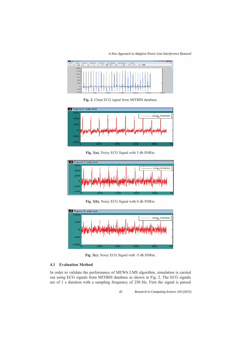
Fig. 2. Clean ECG signal from MITBIH database.
Fig. 3(a). Noisy ECG Signal with 5 db SNRin.
Fig. 3(b). Noisy ECG Signal with 0 db SNRin.
Fig. 3(c). Noisy ECG Signal with -5 db SNRin.
4.1 Evaluation Method
In order to validate the performance of MEWA LMS algorithm, simulation is carriedout using ECG signals from MITBIH database as shown in Fig. 2. The ECG signalsare of 1 s duration with a sampling frequency of 250 Hz. First the signal is passed
45
A New Approach to Adaptive Power Line Interference Removal
Research in Computing Science 103 (2015)

through a channel to introduce channel noise. Further the received ECG is added withthe additive noise to form a noisy signal as shown in Fig. 3(a)(b)(c). This signal is usedas an input signal to evaluate the performance. To quantify the performance of theinterference canceller, signal to noise ratio (SNR) and the correlation coefficient (CC)between the original ECG signal and the filtered ECG signal are calculated. Signal tonoise ratio is measured at the input, as SNRin and at the output as SNRout of the adap-tive canceller. SNR improvement is one of the most important parameter to evaluatethe system performance. SNRin is defined as the ratio of the power of the ECG signalto the power of added noise and SNRout is defined as the ratio of the power of the ECGsignal to the residual noise power. And Correlation Coefficient gives the degree of sim-ilarity between clean ECG and filtered ECG.
4.2 Results and Discussion
Clean ECG signal recorded at Beth Israel Hospital (BIH) in Boston and made avail-able by Massachusetts Institute of Technology (MIT) is taken for simulation. Theclean ECG signal is having 2560 discrete values as shown in Fig. 2. This clean ECGsignal is passed through noisy channel and further polluted by synthetically generatednonstationary interference as shown in Fig. 3 (a)(b)&(c). The algorithm is analyzedby using MATLAB simulation. In order to compare the performance of proposedadaptive algorithm, first the performance of normal LMS algorithm is taken into theconsideration. Thereafter proposed MEWA LMS algorithm is analyzed for differentvalues of step size parameter. Following Table 1 shows the comparative analysis ofnormal LMS algorithm with MEWA LMS algorithm with respect to SNRout and Corr.Coeff values.
Fig. 4 (a)(b)(c) shows the simulation results of MEWA LMS algorithm for improvedvalues of SNRout and Correlation Coefficient (CC) when u=0.01 and No. of taps = 2.In each Fig. plot 1 shows the overlapping of noisy and recovered noisy signal whereplot 2 shows the overlapping of clean ECG and and recovered ECG signal.
Table 1. SNRout and Corr. Coeff. Values for Normal LMS and MEWA LMS.
No.of taps (N)
SNRin (db)
SNRout(db) Corre. Coeff.(CC)
Normal LMS
(u=0.000001)
MEWA LMS
(u=0.01)
Normal LMS
MEWA LMS
2 -10 1.34 32.83 0.6535 0.9833
2 -5 7.82 37.2 0.6457 0.9816
2 0 13.39 41.82 0.6695 0.9832
2 5 18.62 44.04 0.8044 0.9815
46
Abhay R. Kasetwar, Sanjay M. Gulhane
Research in Computing Science 103 (2015)

Fig. 4(a). Output of MEWA LMS for SNRin = –5 db.
Fig. 4(b). Output of MEWA LMS for SNRin = 0 db.
Fig. 4(c). Output of MEWA LMS for SNRin = 5 db.
47
A New Approach to Adaptive Power Line Interference Removal
Research in Computing Science 103 (2015)
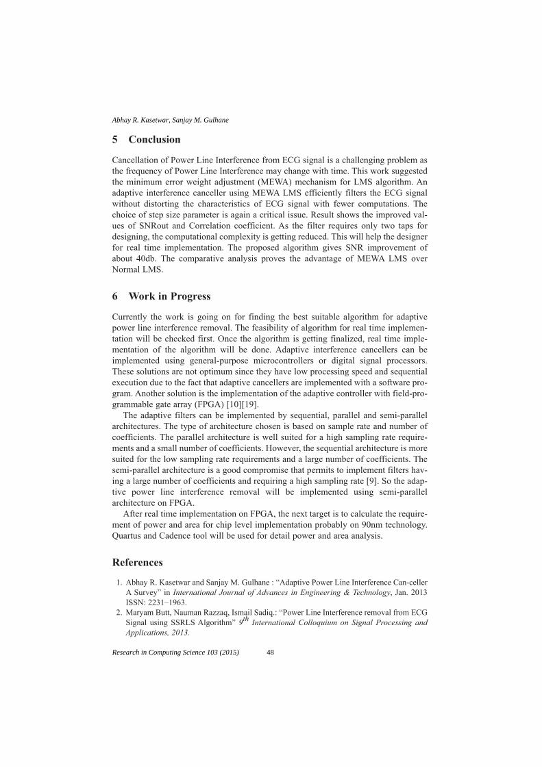
5 Conclusion
Cancellation of Power Line Interference from ECG signal is a challenging problem asthe frequency of Power Line Interference may change with time. This work suggestedthe minimum error weight adjustment (MEWA) mechanism for LMS algorithm. Anadaptive interference canceller using MEWA LMS efficiently filters the ECG signalwithout distorting the characteristics of ECG signal with fewer computations. Thechoice of step size parameter is again a critical issue. Result shows the improved val-ues of SNRout and Correlation coefficient. As the filter requires only two taps fordesigning, the computational complexity is getting reduced. This will help the designerfor real time implementation. The proposed algorithm gives SNR improvement ofabout 40db. The comparative analysis proves the advantage of MEWA LMS overNormal LMS.
6 Work in Progress
Currently the work is going on for finding the best suitable algorithm for adaptivepower line interference removal. The feasibility of algorithm for real time implemen-tation will be checked first. Once the algorithm is getting finalized, real time imple-mentation of the algorithm will be done. Adaptive interference cancellers can beimplemented using general-purpose microcontrollers or digital signal processors.These solutions are not optimum since they have low processing speed and sequentialexecution due to the fact that adaptive cancellers are implemented with a software pro-gram. Another solution is the implementation of the adaptive controller with field-pro-grammable gate array (FPGA) [10][19].
The adaptive filters can be implemented by sequential, parallel and semi-parallelarchitectures. The type of architecture chosen is based on sample rate and number ofcoefficients. The parallel architecture is well suited for a high sampling rate require-ments and a small number of coefficients. However, the sequential architecture is moresuited for the low sampling rate requirements and a large number of coefficients. Thesemi-parallel architecture is a good compromise that permits to implement filters hav-ing a large number of coefficients and requiring a high sampling rate [9]. So the adap-tive power line interference removal will be implemented using semi-parallelarchitecture on FPGA.
After real time implementation on FPGA, the next target is to calculate the require-ment of power and area for chip level implementation probably on 90nm technology.Quartus and Cadence tool will be used for detail power and area analysis.
References
1. Abhay R. Kasetwar and Sanjay M. Gulhane : “Adaptive Power Line Interference Can-cellerA Survey” in International Journal of Advances in Engineering & Technology, Jan. 2013ISSN: 2231–1963.
2. Maryam Butt, Nauman Razzaq, Ismail Sadiq.: “Power Line Interference removal from ECGSignal using SSRLS Algorithm” 9th International Colloquium on Signal Processing andApplications, 2013.
48
Abhay R. Kasetwar, Sanjay M. Gulhane
Research in Computing Science 103 (2015)

3. Yue-Der Lin, Yu Hen Hu: “Power Line Interference Detection and Suppression in ECGSignal Processing,” IEEE Transactions on Biomedical Engineering, Vol.55, No.1January2008.
4. H. N. Bharat, K. M. M. Prabhu: “A New LMS based Adaptive Interference Canceller forECG Power Line Removal,” International Conference on Biomedical Engineering Febru-ary, 2012.
5. Alireza K. Ziarani, Adalbert Konrad: “A Nonlinear Adaptive Method of Elimination ofPower Line Interference in ECG Signals,” IEEE Transactions on Biomedical Engineering,Vol. 49, No. 6 June 2002.
6. Martens S.M.M., Bergmans J.W.M. and Oei S.G.: “ A Simple adaptive interference cancel-lation method for power line reduction in electrocardiography”, proceeding of 25th
Symposium on Information Theory in the Benelux, pp. 49–56 (2004).7. Martens S.M.M., Mischi M., Oei S.G, and Bergmans J.W.M.: “ An improved adaptive power
line interference canceller for electrocardiography”, IEEE Transactions on BiomedicalEngineering, Vol.53, pp. 2220–2231 (2006).
8. B. Widrow et al :”Adaptive noise cancelling : principles and application.” Proceeding of theIEEE, Vol. 63, no. 12, pp.1692–1716. Dec. 1975.
9. Abhay R. Kasetwar and Dr. Sanjay M. Gulhane: “A Survey of FPGA Based InterferenceCancellation Architectures for Biomedical Signals” in International Conference onComputer Communication and Informatics (ICCCI-2013), Jan. 04–06, 2013,Coimbatore,INDIA 978-1-4673-2907-1/13/$31.00©2013IEEE.
10. Mohammed Bahoura, et al.: “FPGA-Implementation of a Sequential Adaptive NoiseCanceller using Xilinx System Generator,” in International Conference on Microelectronics,2009.
11. G. Long, F. Ling, and J. Proakis: “LMS algorithm with delayed coefficient adaptation,” IEEETransaction on Acoustic, Speech & Signal Processing, vol. 37, no. 9, pp. 1397–1405, 1989.
12. Dai Huhe, et al.: “A Novel Suppression Algorithm of Power Line Interference in ECGSignal,” in First International Conference on Pervasive Computing, Signal Processing andApplications, 2010.
13. B. S. Lin et al.: “Removing residual power-line interference using WHT adaptive filter,” inProceedings of Second Joint EMBS / BMES Conference, USA, Oct 23 – 26, 2002.
14. LD Avendano-Valencia, et al.: “Improvement of an Extended Kalman Filter Power LineInterference Suppressor for ECG Signals,” in Journal of Computer in Cardiology, 2007, vol.34, pp. 553 - 556G.
15. Ramanathan S, et al.: “A systolic architecture for LMS adaptive filtering with minimal adap-tion delay,” in Proceedings of 9th International Conference on VLSI Design, Jan. 1996, pp286 – 289.
16. Zhiguo Zhou, et al.: “FPGA-Implementation of LMS Adaptive Noise Canceller for ECGSignal Using Model Based Design,” in IEEE International Symposium on Bioelectronicsand Bioinformatics, Nov 3–5, 2011.
17. N. Jindapetch, S. Chewae, P. Phukpattaranont: “FPGA implementation of an ADALINEadaptive filter for power line noise cancellation in surface electromyography signals” inELSEVIER measurement, 45 (2012) 405–414.
18. G. Chen : “The FPGA Implementation of Kalman Filter,” in 5th WSEAS nternationalConference on Signal Processing, Computational Geometry & Artificial Vision, 2005.
19. R. Ramos et al., “Application by means of FPGA of an adaptive canceller 50 Hz interfer-ence in electrocardiography,” in IEEE Instrumentation and Measurement TechnologyConference, Hungary, May 21–23, 2001.
49
A New Approach to Adaptive Power Line Interference Removal
Research in Computing Science 103 (2015)

UML Behavioral Refactoring for theSpecification of Complex Software Systems
M.T. Chitra1,2 and Sherly Elizabeth2
1University of Kerala2Indian Institute of Information Technology and Management - Kerala
{chitra,sherly}@iiitmk.ac.in
Abstract. Behavioral models play a prominent role in specifying soft-ware systems by facilitating the abstract behavior views and analyzingthe elementary aspects of a system. The sequence diagram, one of thekey behavioral diagrams in UML, provides intuitive ways to capture re-quirements and scenarios as a sequence of events. The paper proposesa generic framework for effective code generation from UML models.The proposed framework acts as an interexchange format that helps tocombine the structural and behavioral constraints of the system objectsassociated thereby facilitating consistent source code generation. ModelRefactoring contributes to improve the software quality and productiv-ity thus mitigating flaws in the system during the design phase itself.The case study presents the refactoring of online simulation of a milloptimization problem in a thermal power plant system.
Keywords: Behavioral diagrams, Model Refactoring.
1 Introduction
The increasing complexity of the software systems demands the advent of noveleffective development approaches that can overcome the major drawbacks of theexisting development technologies. Model Driven Engineering (MDE), fosteredby Object Management Group (OMG) helps reducing the development costsof complex software systems through the use of technologies like Model DrivenArchitecture (MDA) that supports rigorous analysis of software models [2, 3]. InMDA, models are the primary entities for entitling the system at different levelsof abstraction. Models can help to detect inconsistencies or incompleteness inrequirement model by evaluating the simulation of the scenarios.
The Unified Modeling Language (UML) is one of the prevalent languages usedfor modeling complex safety-intensive software systems. It provides a collectionof modeling notations for design specifications to build models that describe thedifferent views on a system during various stages such as requirements analy-sis and design artifacts of software systems. UML Sequence diagrams are now
51 Research in Computing Science 103 (2015)pp. 51–68; rec. 2015-06-03; acc. 2015-06-20

becoming familiar to represent the behavioral specifications of the complex sys-tems. Sequence diagrams emphasize on modeling the interactions between thecollaborating objects participating in the interactions as a time-ordered set ofmessages [1, 3].
However, UML diagrams fail to specify the semantics in representing theentire information to determine the complete system behavior. The lack of formalsemantic specification for UML makes it difficult to analyze the consistencynotion in these diagrams. Hence, several transformation approaches are beingadopted for analyzing and specifying the consistency of behavioral models whichtransform the UML models into some semantic domain where the consistencyconstraints can be represented and validated. The formal specification languageslike OCL, TOCL, Z, etc. helps to add additional information to the diagramthereby ensuring the completeness of the model.
OCL is a declarative, side-effect free, formal specification language used alongwith UML diagrams for specifying the object constraints and queries on theUML models. It precisely defines the well-formedness rules for UML as well asthe OMG-related metamodels. OCL is mainly used to specify the invariants ofobjects as well as the pre and post conditions of the operations [6].
Representing the dynamic behavior of complex time-safety critical systemsis a rigorous task as well as a tough research problem to be taken care of. Itinvolves the careful analysis of the semantic aspects with respect to the systemconstraints. Moreover, there are no model-based techniques or tools availableso far for analyzing such temporal properties in UML behavioral diagrams, es-pecially in sequence diagrams. Existing approaches use model transformationtechniques that transform the UML models to some other language that sup-ports automated analysis, which are also complex and erroneous.
The Temporal OCL (TOCL) finds its significance in this context. The timeand safety related constraints as well as the behavioral specifications, whichare hard to express using OCL can be specified using TOCL, a temporal logicextension of OCL. In this paper, we evaluate the impact of OCL and TOCL alongwith UML behavioral diagrams to completely represent the system behaviorespecially in safety-critical software environments.
Towards this goal, we provide a refactoring approach to embed the staticas well as the temporal constraints involved in the system behavior through adevelopment chain. It constitutes the generation of the behavioral design modelusing UML sequence diagrams, specification of the constraints using OCL andTOCL, generation of code from the behavioral models by applying the refactor-ing approach and the execution and analysis of generated code. This approachhelps in predicting the system behavior at modeling level itself by comparing thesimulation results with real time results. This consequently allows the scientistsor the researchers to work exclusively at modeling level in order to obtain theoptimized system models. They can analyze the scenario specifications directlyfrom the execution model and can add changes accordingly.
The work focuses on interaction modeling, showcasing the dynamic aspectsof the interaction between the participating objects. The dynamic modeling
52
M.T. Chitra, Sherly Elizabeth
Research in Computing Science 103 (2015)
includes visual specification of the system functionalities in detail, where thefunctionalities are realized through the message passing between the objectsparticipating in the interaction. The paper discusses about the development of aframework which shows the automated refactoring of UML interaction diagrams,especially the sequence diagram designs, to improve the understandability andmaintainability of the design for the efficient source code generation process.
This paper is an extended work and its main new contribution is that theframework has been enhanced with the potential of including a set of safetyand temporal constraints in addition to the static constraints of the system [16].The work proposes a novel approach that yields an interexchange framework toinclude the complex system behaviors into UML Sequence diagram design asconstraints, thereby enriching the model elements with the necessary details ofthe system without affecting its external behavior.
Incompleteness in the generated source code may often arise due to the ab-sence or failure in representing all possible information regarding the objectsthat participate in that system. The constraint specification languages play anintelligent role here, by removing this inconsistency in the model design whichin turn reflects in the completeness of the generated source code. The proposedframework paves the way for improving the software code quality and produc-tivity fulfilling all the specified system requirements during the code generationprocess.
The main contributions of this work can be summarized as follows:
– The behavioral refactoring approach in sequence diagram designs is pro-posed, which paves a way to incorporate static, temporal and safety relatedconstraints into the design and derive a refactored interexchange model fromthe existing SD specification.
– To provide a generic behavioral pattern for implementing the proposed refac-toring methodology in UML models that provides a space for consistent codegeneration of software systems.
The remainder of this paper is structured as follows: Section 2 gives therelated works and identifies and explains the different refactoring activities. Sec-tion 3 describes the proposed refactoring approach. Section 4 presents the im-plementation of the approach through a case study discussion. Finally, Section 5shows the results and discussions part of the case study and Section 6 concludes.
1.1 Background
The software refactoring is an emerging area where a lot of researches are beingcarried out on exploring the ways to address refactoring in a consistent manner.Refactoring revolutionizes the design by applying some effective process for im-proving code quality. The term refactoring was instigated in 1992 by William F.Opdyke in his research work in the context of object-oriented software to supportsoftware evolution and reuse. He defined refactoring as “behavior preserving pro-gram restructurings or transformations containing particular preconditions that
53
UML Behavioral Refactoring for the Specification of Complex Software Systems
Research in Computing Science 103 (2015)

must be verified before the transformation can be applied in order to make thedesign of a program clearer and to make it easier to add new features” [7, 8].
Refactorings can also be applied to reduce or eliminate redundant parts ofprogram codes [7]. Martin Fowler defined the process of refactoring as “a changemade to the internal structure of software to make it easier to understand andcheaper to modify without changing its observable behavior”. He proposed therefactoring catalog which focuses on manual refactoring, demonstrated with ex-amples regarding the principles of refactoring, the useful ways to identify andfind the associated low-level refactoring(s) that helps fixing a code problem in acontrolled and efficient manner [9].
Mens et al., in their review on model-driven refactoring discussed on the latestapproaches in model refactoring and also the various challenges encounteredwhile applying refactoring on model level [13]. Mohamed et al. discussed ontheir the existing model refactoring approaces based on feature based model-driven taxonomy [14]. Most of the investigations focus on UML class diagrams,for applying model refactorings [10]. There are only a few approaches that focusrefactoring behavioral diagrams and prove their behavior preservation propertiesin a standard way. G. Sunye et al. were the first to present a set of refactoring(s),particularly on UML class models and state machine models, and explained howthey can be modeled so as to preserve the behavior of a UML model. They showedthat refactorings can be defined for UML in such a way that their behavior-preserving properties are protected, based on OCL constraints defined at themetamodeling level [11].
Alessandro Folli and Tom Mens used Algebraic Graph Grammar tool tosupport refactoring on the UML designs. They focus on class models and statemachine models and define a metamodel similar to the UML meta model as atype graph. The limitation of this work is that this type graph can represent onlythe simplest version of the UML metamodel [17]. France et al. described a metamodeling approach to pattern-based model refactoring in which refactoring(s)are used to introduce a new design pattern instance to the model [18].
Several formalisms have been suggested to examine model refactoring(s).Most of these propose exhibiting model refactoring in a declarative way. Graphtransformation theory was used in several works for describing model refactoringand formal properties have been used to review these refactoring(s) [15].
Most of the refactoring approaches focused on code-level refactoring and onlya limited works address the model refactoring approaches and especially withclass diagrams [13]. But while taking care of the behavior preservation of designmodels, we need to rely on behavioral models and the constraints associatedwith them. Only a few works are available in the literature with respect torefactoring of behavioral models. None of the existing approaches can be usedto verify operation-based model refactoring that involves changes to operationspecification. The core idea presented in this paper focuses on facilitating theintegration of system behavioral properties throughout the time point at differentabstraction levels one wants to guarantee for the safe or normal execution of thesystem.
54
M.T. Chitra, Sherly Elizabeth
Research in Computing Science 103 (2015)

2 The Conceptual Approach
2.1 Refactoring the Behavioral Specifications
Model transformation is the process of modifying the source model to producethe target model. Refactoring is a model transformation approach which restruc-tures the system by altering its internal behavior without affecting the externalbehavior [1, 2]. Modifying the UML model by enriching with the necessary con-straints will significantly increase the quality of the design as well as the gener-ated source code from it. The process of refactoring enables the model to adaptto future extensions.
By definition, refactoring should ensure behavior-preserving transformationsof an application. It means that the external behavior of the model before andafter the refactoring must remain the same. The major problem faced by design-ers is to measure the actual impact of modifications on the various design views,as well as on the implementation code which serves as a valid proof to prove thecorrectness of system and hence showing the behavior preservation property ofrefactoring approach. Another crucial task here is identifying or determining theexact element to which the refactoring has to be applied.
We are applying the refactoring approach in UML sequence diagrams, whichprimarily shows the behavioral interactions between the objects participatingin the system. Such behavioral transformations need extra care as their changeraises some difficulties.
In the proposed work, the model refactoring is applied to the lifeline modelelement of the sequence diagram design for ensuring the correctness of the sys-tem. Since the primary focus of the sequence diagram is to specify the interactionbetween the collaborating objects, represented as lifelines, it has been chosen asthe focal point for refactoring.
We also need to justify why the behavior preservation condition holds forthese model transformations:
– Adding the constraint schema into the lifeline model element does not makeany modification to the behavior of that element. Rather, we are only givingspace to group all the data related to that model element into a commonpoint in order to improve the understandability.
The overall architecture of the refactoring process proposed in this work is shownin Figure 1.
The XML Metadata Interchange (XMI) is OMG standard interchange for-mat used in UML models for exchanging metadata information via XML. Itincludes information about elements in a model and their relationships. Thetransformation of the models into XMI is indeed a breakthrough in facilitatinginteroperability across various tools and platforms [5]. The XMI generated wouldthen be fed into an XMI parser to retrieve the meta model information which in-turn is used for the generation of source code. Besides, OCL and TemporalOCLalso supplements more precise information specification in the UML behavioralmodel. The work is an attempt to allow the specification of inter-object scenariosfor object-oriented system models in a succinct expressive manner.
55
UML Behavioral Refactoring for the Specification of Complex Software Systems
Research in Computing Science 103 (2015)

Fig. 1. Architecture of the Refactoring process
2.2 Generation of the OCL-TOCL Framework
The work focuses on developing X-CodeFrame, an XML code framework for rep-resenting OCL and TOCL constraints into UML behavioral models, especiallythe Sequence diagram model thereby facilitating automatic behavioral code gen-eration. This approach helps in simplifying the transformation of the static, tem-poral and safety-related constraints of the system, thereby smoothening the codegeneration process.
The constraints that are typically hard to express in OCL, which entitles thetemporal and safety related issues of the system are specified using the temporalOCL (TOCL). The static as well as the temporal constraints specified for asystem using OCL and TOCL are parsed for framing the constrained elements inorder to generate the framework as per the defined schema [schema No-Fig.]. Theextracted constraints are then set appropriately into the OCL-TOCL frameworksby matching the context < classname > attribute.
An XML Schema Definition (XSD) typically called an XML schema, is thede facto standard for describing XML documents, controlled by the World WideWeb Consortium (W3C). The XML schema formally defines the XML document
56
M.T. Chitra, Sherly Elizabeth
Research in Computing Science 103 (2015)

structure accompanying the rules for data content and semantics. The OCLschema proposed here defines an XSD file that provides the design pattern ofhow the constraints will set within the XMI file obtained after the refactoringprocess.
The OCL-TOCL schema is the backbone of the proposed UML refactor-ing process. Based on the defined schema rules, the constraints are embeddedinto the XMI file of the UML model thereby refactoring it for quality sourcecode generation. The basic types that we are considering for the schema frame-work generation are the invariants, methods, pre-condition and post-conditionoperations.
The schema defines the specification rules for framing the constraints appro-priately associated with each of the objects participating in the system interac-tion. For each class defined in the constraint files (OCL/TOCL) there will bean < extendedConstraints > tag generated which is the root element for theconstraint construction framework. All the constraints that belong to a partic-ular class will come to an individual < extendedConstraints > tag created forthat class. It includes the class name details using the attribute context and alsostores the file type within the type attribute.
Fig. 2. Extended constraints
The schema template structure for adding invariants into the OCL-TOCLframework is as follows. The < MethodDetails > tag is the main tag elementinside the < extendedConstraints > tag which represents the whole constraintblock within a particular class based on the nature of the constraints. The< body > tag element sets the constraints within the < MethodDetails > appro-priately. The < constraints > tag is the complex type tag set that helps in iden-tifying all the constraint expressions, operations etc in the < MethodDetails >and include these entities as individual elements under the < constraint >tag within it. The schema template structure for generation of an operation ormethod is as shown in Fig. 3.
For the execution of a method in any complex system generally includes aprecondition which must be considered for a safe system functioning, a bodypart which includes the actual functionality to be performed and a postcondi-tion operation in which the status of the generated output is checked for fur-ther processing of the system. Hence the syntax for generation of the methodschema also include these as the key factors while framing data with respect toa method. The < precondition > tag element helps in representing all thoseconditions for checking the pre-conditions that should satisfy or perform if anybefore performing the actual method body. The < body > tag include the ex-
57
UML Behavioral Refactoring for the Specification of Complex Software Systems
Research in Computing Science 103 (2015)

Fig. 3. Schema template structure for generation of an operation or method
pression and operations that have to be taken place within that method andthe < postcondition > tag represents all those constraints that must have to beexecuted after the method execution.
The generation of java class files corresponding to the OCL schema is doneusing JAXB (Java Architecture for Xml Binding), which directly binds theXSD/XML element to particular fields of java classes and vice versa using theproperties marshalling and unmarshalling.
The OCL files containing the static constraints and the TOCL files whichcontain the temporal and safety related constraints for the system are parsed.The constraints are parsed and extracted in a way that helps in fixing the con-text to which the respective specification refers to in the generated OCL-TOCLframeworks. The constraints extracted are set with the associated java objectsof the java classes created using JAXB.
The generated OCL TOCL frameworks are then injected into the XMI of theSequence diagram model based on the lifelines associated with it.
The OCL -TOCL framework generation process is shown as Algorithm 1.
Algorithm 2 explains the process of filling the constraint objects with appro-priate constraint body tag elements.
58
M.T. Chitra, Sherly Elizabeth
Research in Computing Science 103 (2015)

Algorithm 1. X-CodeFrame Generation
Require: OCL file for sd ’s (OCLsd) and also TOCL file for sd ’s (TOCLsd), if any.Ensure: XMLframework of the constraints w.r.t. different contexts referred.1: begin2: Initialize the ocl-tocl parser with the input3: Read OCL / TOCL file4: for each line in file do do5: segregate the contents against the context6: for each new content in context do do7: create an object of ExtendedContraints with type OCL/TOCL8: store the object against context9: parse the context string
10: extract the details context data elements like class name, constrainttype,constraint name, return type if any
11: end for12: for each new constraint within a context do13: get the ExtendedConstraints object against a context14: add an object of MethodDetails under ExtendedConstraints15: invoke populateConstraintBody()16: end for17: iterate the list of ExtendedConstraints of all context18: marshall the objects to the XML content19: store it against the context20: end for
2.3 Applying Refactoring to the Model: An Algorithmic approach
Identification and extraction of the exact information that represent function-alities or behavior from the UML models are crucial. This work is proposing aautomated refactoring approach for the scenario based UML designs, especially,the UML sequence diagrams, to model the complex system behaviors, henceforthbuilding the behavioral scenarios for individual subcomponents of the system.Refactoring supports a highly dynamic software lifecycle by improving the inter-nal structure of a piece of code block without altering its external behavior. Theoperation specifications which cannot be directly included in the UML designsare expressed using the static as well as the temporal constraint languages.
Given a model M which consists of model elements which are associated withit to perform the behavioral aspects as per the system requirement specificationbased on the metamodelling standards (IM). Applying model refactoring in themodel MR = (pre, TR), where pre is the precondition or set of rules that modelmust preserve and satisfy, and TR is the model transformation that is appliedto the model.
The Algorithm 3 describes the whole process taken place during the UMLrefactoring approach.
We illustrate how the refactoring process will happen through the simula-tion of the mathematical modeling process for optimizing the time factor in apulverizing process in a thermal power plant system.
59
UML Behavioral Refactoring for the Specification of Complex Software Systems
Research in Computing Science 103 (2015)

Algorithm 2. The populateConstraintBody()
Require: ExtendedConstraints object for a contextEnsure: Modified ExtendedConstraints object with constraint body1: begin2: if Precondition then3: create an object of ExtendedConstraints.MethodDetails.Preconditions4: create Constraints object within Preconditions5: set the expression string to the Precondition constraints6: else if Postcondition then7: create an object of ExtendedConstraints.MethodDetails.Preconditions8: create Constraints object within Preconditions9: set the expression string to the Precondition constraints
10: else if Body or inv then11: create an object of ExtendedConstraints.MethodDetails.Preconditions12: create Constraints object within Preconditions13: set the expression string to the Precondition constraints14: end if15: return the modified object of ExtendedConstraints16: end
Algorithm 3. The Automated UML Refactoring Process
Require: ExtendedConstraints object for a contextEnsure: Modified ExtendedConstraints object with constraint body1: begin2: if Precondition then3: create an object of ExtendedConstraints.MethodDetails.Preconditions4: create Constraints object within Preconditions5: set the expression string to the Precondition constraints6: else if Postcondition then7: create an object of ExtendedConstraints.MethodDetails.Preconditions8: create Constraints object within Preconditions9: set the expression string to the Precondition constraints
10: else if Body or inv then11: create an object of ExtendedConstraints.MethodDetails.Preconditions12: create Constraints object within Preconditions13: set the expression string to the Precondition constraints14: end if15: return the modified object of ExtendedConstraints16: end
3 Case Study : The Coal Pulveriser OptimizationProblem
We demonstrate the capability of the proposed refactoring approach thoughthe online coal pulverizing mill optimization problem [16]. In this system, wehave considered both the static as well as the behavioral properties involved inthe pulverizing process to demonstrate the applicability of the approach. The
60
M.T. Chitra, Sherly Elizabeth
Research in Computing Science 103 (2015)

main function of the pulverizing mill is to grind and dry the moisturized rawcoal supplied to it from the coal storages. The two main classes involved in thepulverisation process in a coal mill are the CoalStorage and the Pulveriser.
The proposed system behavior is modeled using the UML sequence diagram.The safety and time related constraints as well as the static constraints are ex-pressed as TOCL and OCL files respectively. The model is exported as an XMIfile and is parsed appropriately for extracting the relevant tag data elements forthe code generation process. The OCL as well as the TOCL files are simultane-ously parsed to extract the relevant details into the corresponding tag elementsin the XMI file using the proposed X-CodeFrame framework.
The UML together with the OCL and TOCL helps in representing the factsthat belong to the behavioral level completeness of the system. The constraintsof the pulveriser which cannot be typified visually are represented using OCLand TOCL files. The pre and post conditions to be satisfied and the invariantsof the system model specified using the OCL file are embedded to the designmodel by the applying the refactoring approach proposed in the work in orderto accomplish the model consistency. The pulveriser optimization process simu-lation is performed by transforming the mathematical system model using theObject Constraint Language. Along with the sequence diagram model informa-tion the temporal as well as the static constraints related with the CoalStorageand the Pulveriser sub systems are also supplied to the model in order to enrichthe design data for the code generation process.
3.1 Simulating the Online Coal Pulverisation Process Optimization
The following mathematical model explains the coal pulverisation process [19,20]. The model is converted to discrete time form for the purpose of online im-plementation. Figure 2 illustrates the overall online pulverising mill optimizationprocess. The mill model variables are monitored dynamically in real time. Theunknown parameters in the equations are estimated using evolutionary compu-tation technique (Genetic Algorithms) and system simulation techniques basedon the on-site measurement data. The normal pulverisation process is describedmathematically using the following equations:
61
UML Behavioral Refactoring for the Specification of Complex Software Systems
Research in Computing Science 103 (2015)

Fig. 4. Online mill performance simulation
The main input variables supplied to the pulveriser system include raw coalflow into the pulveriser, primary air differential pressure and primary air inlettemperature. The output variables include pulveriser differential pressure, outlettemperature and mil current. The online coal mill optimization process is spec-ified as a constraint file as shown below. During the refactoring process theseequations are affixed under the < body > tag elements section of the Pulveris-ing() method call.
The values of the constant co-efficients are obtained using the Genetic Al-gorithm. The code generation helps the researchers and experienced engineersin analyzing and comparing the simulation results of the online mill model withthe real plant data set values and thereby improving the mill performance.
3.2 OCL Constraints in the Coal Pulverising Process
This section presents the approach by specifying the temporal properties associ-ated with the pulverisation process in a coal-fired thermal power plant system.The structural constraints that must necessarily hold true or checked during thepulverization process are represented as invariants using the OCL file.
Mc = ((Wc - (k15 * self.Mc)) * T )
Mpf = (((k15 * self.Mc) - (self.Wpf)) * T)
DPmpd = (((k11 * self.Mpf + (k12 * self.Mc) - (k13 * self.DPmpd))) * T)
62
M.T. Chitra, Sherly Elizabeth
Research in Computing Science 103 (2015)

Tout = (((((k1 * self.Tin) + k2) * self.Wair) - (k3 * self.Wc) -
(((k4 * self.Tout) + k5) * (self.Wair + self.Wc)) +
k14 * ((k6 * self.Mpf) + (k7 * self.Mc) + k8) +
((k17 * self.Tout))) * T) + self.Tout
P = (k6 * self.Mpf) + (k7 * self.Mc) + k8
DPmill = k9 * self.DPpa
Wpf = k16 * self.DPpa + self.Mpf
The following are a few constraints associated with the two classes CoalStor-age and PowerPlant in the thermal power plant system:
context CoalStorage inv cosize:CoalSize=20
context CoalStorage inv hval: HGI=55
The invariants that must hold true for the CoalStorage class are:
context CoalStorage inv cosize:CoalSize=20
context CoalStorage inv hval: HGI=55
The typical invariants that must hold for the Pulveriser class are as shownbelow.
context Pulveriser inv: Wc $<=$ 45
context Pulveriser inv: Wair $<=$ 75
context Pulveriser inv: Tin $<=$ 300
context Pulveriser inv: DPpa $<=$ 180
context Pulveriser inv: outlet temperature $<=$100
context Pulveriser inv: DPmill $<=$ 500
context Pulveriser inv: P $<=$ 60
context Pulveriser inv: if a.Stage = 3 then
Speed=54 else Speed=52 endif
context Pulveriser inv:if a.Stage = 3
then self.Type = ’HP803PXBowl’
else self.Type = ’XRP763BowlRoller’endif
context Pulveriser inv:if CoalHGI = 55 and CoalMoisture = 0.1
and CoalFineness = 0.7 then
if a.Stage = 3 then self.Capacity2 = 39.9 else
self.Capacity2 =33.8
endif
else self.Capacity2 $ <>$ 0
endif
3.3 Safety and Temporal Constraints in the Coal PulverizingProcess
The temporal constraints involved in the coal milling process include the safetyand time related aspects of all the classes or objects participating in that process.For the CoalStorage class the main temporal constraints involved are:
63
UML Behavioral Refactoring for the Specification of Complex Software Systems
Research in Computing Science 103 (2015)

1. Failure in the level of the minimum storage level or maximum storage leveloccurred; that means the coal level exceeds the limit of the maximum storagelevel or has reached the minimum level.
For the Pulverizer class the main temporal constraints to be considered are:
1. The system is in initialization mode until all the physical sub components orunits inside the pulveriser are in ready mode and all the external attributessupplied to the system satisfie the normal range values for proper functioningof it or a failure in the level of coal quantity supplied to the pulverizing millhas been identified.
2. The system is in the normal mode, which is the standard operating modewhen the program tries to maintain the raw coal level in the pulveriser be-tween the level of values with which all physical units are operating correctly.
The below listed are a few safety and temporal constraints associated withthe coal pulverisation process.
When the Pulveriser system is in the initialization mode, it remains in thismode until all physical units are ready or a failure in the pulverising mill hasoccurred.
Instantly the program recognizes a failure in the Coal Mill system until itgoes into the rescue mode.
Failure of any of the physical or measured units except the coal mill puts theprogram in to degrade mode.
When the Coal Mill system is in the initialization mode and a failure of thecoal mill is detected, it puts the program into emergency stop.
64
M.T. Chitra, Sherly Elizabeth
Research in Computing Science 103 (2015)

4 Results and Discussions
The UML SD design model for the coal pulverization process is shown in Fig-ure 5:
Fig. 5. UML Sequence diagrams
The OCL framework generated for the OCL constraints given below is asshown in Figure 6. Here the CoalStorage class has two constraints associatedwith it, which are converted into two < MethodDetails > elements under the< ExtendedConstraints > object tag.
The OCL-TOCL framework generated for the mill optimization process is asfollows.
The framework generated for the preconditions and postconditions specifiedas OCLconstraints that must satisfy for the Pulveriser object is:
The code framework generated for invariants of the Pulveriser subsystem is:
5 Conclusion
This paper concentrates on providing a generic framework for refactoring thespecification of complex systems modeled using UML2.0 sequence diagrams. Itfocuses on combining the structural and the behavioral constraints, thereby of-fering a path for consistent and quality source code generation. The system hasbeen formally modeled using the OCL/TOCL language to provide explicit andprecise system information to the design. A generic template framework hasbeen built based on the constraints as well as the UML sequence metadata of
65
UML Behavioral Refactoring for the Specification of Complex Software Systems
Research in Computing Science 103 (2015)

Fig. 6. The OCL framework generated for the OCL constraints
Fig. 7. The XCodeFrame generated for the online coal mill optimization process forthe Pulveriser subsystem
the system by using refactoring approach. The proposed method facilitates themathematical verification of pulveriser system in a thermal power plant. Therepresentation of extra information as static as well as temporal constraints at-tached to certain locations of the objects lifelines in the sequence diagram allowsthe identification of gaps and contradictory specifications during the source codegeneration process.
6 Acknowledgments
The authors would like to thank the Control and Instrumentation Group, CDAC,Thiruvanathapuram for providing the raw plant data of pulverising mill which isused for modeling and validating the system. This work is supported by SPEED-IT programme of Kerala State IT-Mission under Govt.of Kerala.
66
M.T. Chitra, Sherly Elizabeth
Research in Computing Science 103 (2015)

Fig. 8. The preconditions and postconditions specified as OCLconstraints that mustsatisfy for the Pulveriser object
Fig. 9. The code framework generated for invariants of the Pulveriser subsystem
67
UML Behavioral Refactoring for the Specification of Complex Software Systems
Research in Computing Science 103 (2015)

References
1. Unified Modelling Language, http://www.uml.org/.2. Object Management OMG. Unified Modeling Language Specification 2.0:
Infrastructure. Technical Report ptc/03-09-15, OMG (2003).3. G. Booch, J. Rambaugh, and I. Jacobson, The Unified Modeling Language
User Guide, Addison-Wesley (1999).4. Model Driven Architecture, White Paper, Object Management Group OMG,
May (2014).5. XML Metadata Interchange, www.omg.org/spec/XMI/6. OMG, Object Constraint Language (OCL) Specification, version 2.0,2006
http://www.omg.org/spec/OCL/2.0/7. Opdyke, W.F.: Refactoring: A Program Restructuring Aid in Designing
Object-Oriented Application Frameworks, PhD thesis. Univ. of Illinois(1992).
8. Roberts, D.: Practical Analysis for Refactoring. PhD thesis. Univ. of Illinois(1999).
9. Fowler, Martin: Refactoring: Improving The Design of Existing Code. Pear-son Education India (1999).
10. Astels, Dave: Refactoring with UML. In: 3rd International Conference oneXtreme Programming and Flexible Processes in Software Engineering, 67–70 (2002).
11. Suny, G., Pollet, D., Le Traon, Y., Jzquel, J. M.: Refactoring UML models. InInternational Conference on Unified Modeling Language UML -2001. LNCS2185. Springer Berlin Heidelberg, 134–148 (2001).
12. Maddeh, M., Romdhani, M., Ghdira, K.: Classification of Model RefactoringApproaches. Journal of Object Technology, 8.6, 143–13958 (2009)
13. Mens, Tom, Tourw, Tom: A survey of software refactoring. Software Engi-neering, IEEE Transactions on 30.2, 126–139 (2004).
14. Mens, Tom, Taentzer, Gabriele, Mller, D.: Model-driven Software Refactor-ing. Model-Driven Software Development: Integrating Quality Assurance,170–203 (2008).
15. Mens, Tom, Taentzer,Gabriele, Mller, Dirk.: Challenges in model refactoring.In: 1st Workshop on Refactoring Tools, University of Berlin. Vol. 98 (2007).
16. Chitra M. T., Elizabeth Sherly.: Refactoring sequence diagrams for codegeneration in UML models. In IEEE Int. Conf. on Advances in Computing,Communications and Informatics ICACCI, 2014, 208–212 (2014).
17. Folli, Alessandro, Mens, Tom.: Refactoring of UML models using AGG. Elec-tronic Communications of the EASST (2008).
18. France, R., Chosh, S., Song, E., Kim, D. K.: A metamodeling approach topattern-based model refactoring. Software, IEEE, 20(5), 52–58 (2003).
19. Y. G. Zhang, Q. H. Wu, J. Wang, G. Oluwande D. Matts, and X.Zhou.:Coal Mill Modeling by Machine Learning Based on Onsite Measurements,Energy Convers. IEEE Trans., 17(4), 549–555 (2002).
20. J. Wei, J. Wang and Q. H. Wu.: Development of a Multisegment Coal MillModel Using an Evolutionary Computation Technique, IEEE Trans.EnergyConvers., 22(3), 718–727 (2007).
68
M.T. Chitra, Sherly Elizabeth
Research in Computing Science 103 (2015)
Electronic System for Orientation Control and ObstacleAvoidance for Underwater Glider without a Rudder
Yuvraj N. Patil1, V. S. Aneesh2, M. T. Abhilash3, and Swati Kadlag4
1Student, Dept. of Electronics and Telecommunication Engineering,Symbiosis Institute of Technology (a constituent of SIU),
Pune – 412115, [email protected]
2Technical officer, Defence Avionics Research Establishment (DARE),DRDO-Bangalore, India.
[email protected] Prof., Dept. of Electronics, DRDO-DIAT(DU),
Pune, [email protected]
4Prof., Dept. of Electronics, Symbiosis Institute of Technology (a constituent of SIU),Pune – 412115, India.
Abstract. Autonomous underwater gliders are classified in buoyancy operated longendurance underwater vehicles. The glide control algorithm has been developing formany designs. A system is proposed as an improvement to the existing designs toachieve glide control with 3 chamber internal hydraulic system and to avoid obsta-cles in its saw tooth motion profile and the orientation control that can be achievedwith injection of fluids in internal tanks instead of relying on rudder or movable inter-nal mass. Two algorithms for obstacle avoidance and correcting its approach vectorsi.e. a self correcting mechanism with sensors and servo motors is represented. Theonboard embedded system developed with payload sensors, navigation, communica-tion and actuator control of the prototype design is also discussed in general.
Keywords: Gyroscope; Ultrasonic; compass; Obstacle; Servo; Prototype;Compensation; Orientation.
1 Introduction
An autonomous underwater glider goes in a saw tooth motion with some changes in itsbuoyancy. Such vehicles are small, low power and long endurance and are used formany applications [1]. The hydrodynamics of existing underwater gliders have beendeployed and tested in various environments [2]. However there can be more tech-niques than those used for controlling the motion of a glider. There exists a scope forsmart techniques like obstacle avoidance, change in use of rudders and movable inter-nal mass to control the steering of the glider etc.
69 Research in Computing Science 103 (2015)pp. 69–81; rec. 2015-06-03; acc. 2015-06-20
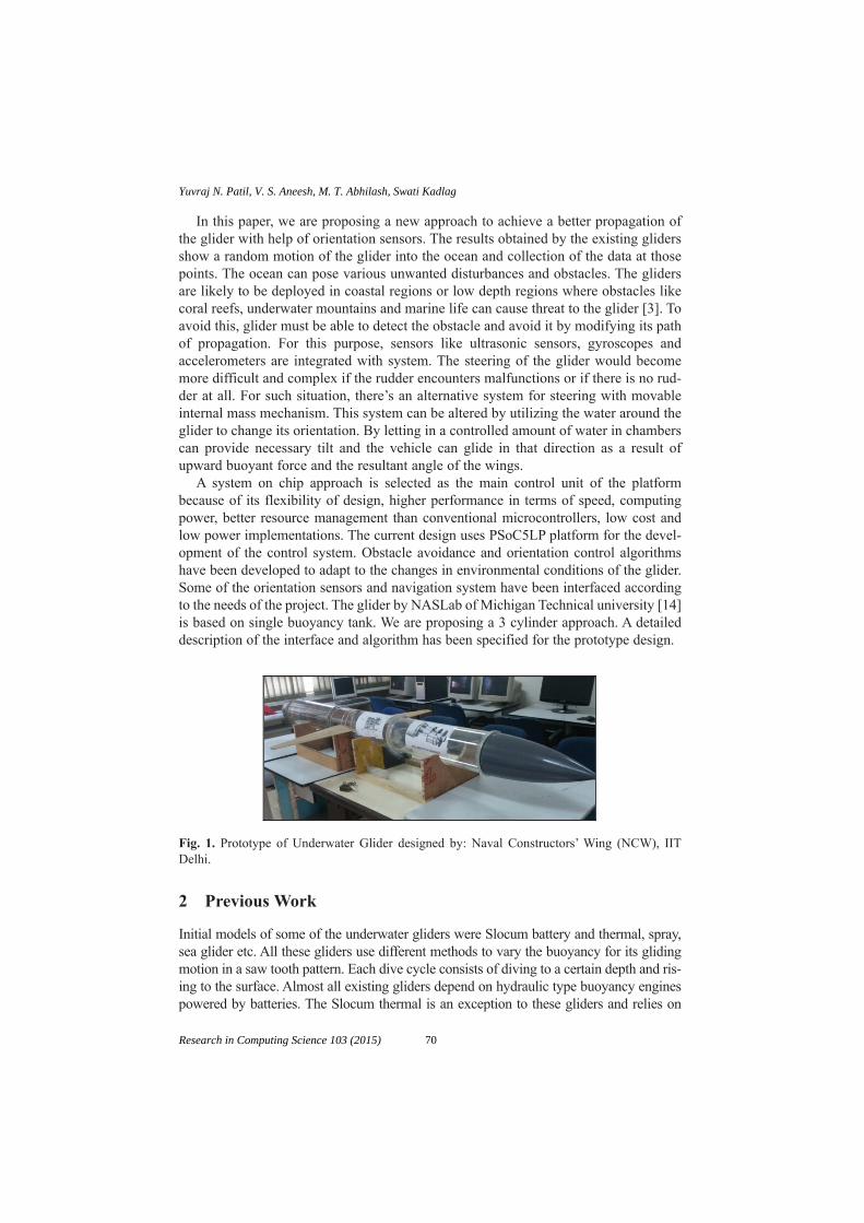
In this paper, we are proposing a new approach to achieve a better propagation ofthe glider with help of orientation sensors. The results obtained by the existing glidersshow a random motion of the glider into the ocean and collection of the data at thosepoints. The ocean can pose various unwanted disturbances and obstacles. The glidersare likely to be deployed in coastal regions or low depth regions where obstacles likecoral reefs, underwater mountains and marine life can cause threat to the glider [3]. Toavoid this, glider must be able to detect the obstacle and avoid it by modifying its pathof propagation. For this purpose, sensors like ultrasonic sensors, gyroscopes andaccelerometers are integrated with system. The steering of the glider would becomemore difficult and complex if the rudder encounters malfunctions or if there is no rud-der at all. For such situation, there’s an alternative system for steering with movableinternal mass mechanism. This system can be altered by utilizing the water around theglider to change its orientation. By letting in a controlled amount of water in chamberscan provide necessary tilt and the vehicle can glide in that direction as a result ofupward buoyant force and the resultant angle of the wings.
A system on chip approach is selected as the main control unit of the platformbecause of its flexibility of design, higher performance in terms of speed, computingpower, better resource management than conventional microcontrollers, low cost andlow power implementations. The current design uses PSoC5LP platform for the devel-opment of the control system. Obstacle avoidance and orientation control algorithmshave been developed to adapt to the changes in environmental conditions of the glider.Some of the orientation sensors and navigation system have been interfaced accordingto the needs of the project. The glider by NASLab of Michigan Technical university [14]is based on single buoyancy tank. We are proposing a 3 cylinder approach. A detaileddescription of the interface and algorithm has been specified for the prototype design.
Fig. 1. Prototype of Underwater Glider designed by: Naval Constructors’ Wing (NCW), IITDelhi.
2 Previous Work
Initial models of some of the underwater gliders were Slocum battery and thermal, spray,sea glider etc. All these gliders use different methods to vary the buoyancy for its glidingmotion in a saw tooth pattern. Each dive cycle consists of diving to a certain depth and ris-ing to the surface. Almost all existing gliders depend on hydraulic type buoyancy enginespowered by batteries. The Slocum thermal is an exception to these gliders and relies on
70
Yuvraj N. Patil, V. S. Aneesh, M. T. Abhilash, Swati Kadlag
Research in Computing Science 103 (2015)

thermalocline of ocean to convert solid medium to liquid and again from liquid to solidstate [4]. It results in its displacement and helps to propagate in desired direction. However,this method restricts its functionality to areas where thermocline is well developed.
The Seaglider has a TT8 microcontroller as its electronic platform which usesMotorola MC68332 M.C. with 12-bit ADC and power management circuits [5]. It basi-cally has conductivity temperature depth (CTC) sensing components on board. TheSeaglider relies on a satellite communication link to transmit onboard data to the missioncomputer [6]. Whereas the Spray is a TT8 controlled glider that utilizes subsystems tocontrol attitude and buoyancy variations, data acquisition, storage and transmission oversatellite channel [7]. Along with CTDs, the spray also has flurometers, altimeter, Iridiumsatellite communication system, turbidity and dissolved oxygen measurement system.
The author [8] described selection of piston operated tanks for the prototype. Thebasic algorithm of the buoyancy engine was clockwise and anti-clockwise motion of aDC motor achieved that simulated to and forth motion of the piston in tanks that wouldresult in a saw tooth profile. The onboard sensors included a temperature and a pressuresensor. The data from these sensors was stored onto a SD card and transmitted usingXBee s2b Pro wireless Zigbee module after each dive cycle. However, the system wasneither mounted on glider body nor was tested in actual or virtual environments.
3 Present Prototype Design
The microcontroller platform for the onboard control system remains to be PSoC5LPfrom Cypress. The data storage is in SD card as done previously and the trans-receivermodule is still XBee s2b Pro. However some modifications to the existing design havebeen made as follows.
3.1 Buoyancy Engine
In previous design, a DC motor simulated the action of a piston operated buoyancyengine. The design approach was for a single cylinder mount for the periodic chargingand discharging to result into a saw tooth motion. However the motor did not drive thepiston mechanism and just simulated the change in rotation periodically. Also thedesign did not take into account the steering or the orientation control system of theglider. This gave rise to following objectives for a modified design.
• Build a piston operated cylinder structure for testing the algorithms.• Couple the DC motor to a rack and pinion mechanism to drive a piston of a syringe
cylinder. • Modify the engine to a 3 cylinder design to provide orientation control• Interface servo motors to operate pistons precisely
Unlike the spray that had a movable internal mass mechanism for steering [9], thedesign would make use of water from outside the glider body for similar operation.This system is also suitable for scenarios where rudder is not present or has encoun-tered a malfunction.
71
Electronic System for Orientation Control and Obstacle Avoidance for Underwater Glider ...
Research in Computing Science 103 (2015)

Figures 2, 3, 4 and 5 show the schematics of the proposed three tanks of the glider.However this placement is not tested on actual prototype glider body for the functionalityneither is the position of those cylinders fixed as shown in above figures. The control sys-tem block consists of motors and rack and pinions that drive the pistons in those cylinders.
The position of the tanks inside the body is shown in Figure 6 and orientationchange with respect to initial position is shown in Figure 7. The modeling parametersfor the mechanical system are skipped in this paper and more emphasis is given ondeveloping an algorithm for their operation.
Fig. 2 & 3. Top view of the design of demonstration set up,Front view of the design showingposition of servo motors and a DC motor with respect to cylinders.
���
Fig. 4 & 5. Side view of the servo controlled cylinder. Servo motor is connected to a rack andpinion assembly, Side view of the DC motor controlled cylinder responsible for saw tooth pro-file of the glider motion.
Fig. 6 & 7. Buoyancy engine for the prototype design showing location of the cylinders insidethe body of the glider, Glider turning right as one side tank becomes heavier by letting in morewater than the other tank.
72
Yuvraj N. Patil, V. S. Aneesh, M. T. Abhilash, Swati Kadlag
Research in Computing Science 103 (2015)

3.2 Onboard Sensors and Drivers
The board has now been interfaced with orientation sensors which include a 3 axis ana-log accelerometer (ADXL335), a digital gyroscope (MPU6050) and a digital compass(HMC5883L). The payload includes a BMP085 pressure and temperature sensor and aGPS module. Two HCSR04 ultrasonic sensors are interfaced for obstacle avoidance.The PSoC5 at the receiver end has been replaced by a XBee programmer module con-nected directly to PC via USB cable.
The gyroscope, BMP085, and digital compass have i2c interface with PSoC5LPwhere as the ultrasonic sensors are PWM operated. These sensors are basic roboticssensors and might not be suitable for underwater applications. These sensors have sim-ilar interfaces and are used to develop the algorithms. The paper includes making useof the data acquired from these sensors for developing the control algorithm. The DCmotor is interfaced via LM369 motor driver IC as shown.
3.3 Navigation System and Link with Base Station
As the glider surfaces during its saw tooth evolution [1], the base station needs toacquire a fix on the current location of the glider. Based on important parameters suchas high sensitivity of 165dBm, 22mA 3.3V low power consumption is made. UARTinterface, NMEA format Output, the GPS module SKG13C from SkyLab is selectedfor the application. Though the module is accurate up to 3 meters, it is cheap and userfriendly. Also the module is low power and gives complete information data with posi-tion, velocity and time information in serial NMEA protocol. The module is suitablefor most of the portable devices.
The module works on input voltage between 3.0V to 4.2 V and on minimum cur-rent of 100mA. The receiver supports active antenna or passive antenna with maximumgain of 25dB. The module has on full duplex serial channel UART. This port is con-nected to the UART of PSoC5LP to receive data frames continuously that are beingacquired form available satellites. However the acquisition is not continued. The datareception only takes place when the glider is on surface and the reception gets cut offwhen the glider goes inside the water. The GPS module requires 36 sec. for cold startand 1 sec. for hot start. This time depends upon the time for which the glider staysinside the water. The frames are in NMEA format and consist of GGA-GlobalPositioning System Fixed Data, GSA-GNSS DOP and Active Satellites, GSVGNSSSatellites in View and RMC-Recommended Minimum Specific GNSS Data requiredinformation which can be extracted and recorded.
For the communication with base station, XBee Pro s2b trans-receiver is selected. Themodule operates in ISM band (2.4GHz) and has maximum data rate of 250kbps. The Proseries modules have a longer range compared to other modules which is 2 miles of out-door coverage in line of sight. And 200m in indoor scenarios with transmission power of63mW. The module is low power and operates in voltage range between 2.6V to 3.3V.
3.4 Embedded System
The embedded system required for this application is supposed to be low power, lowcost and versatile in nature. The low power operation of the microcontroller gives the
73
Electronic System for Orientation Control and Obstacle Avoidance for Underwater Glider ...
Research in Computing Science 103 (2015)
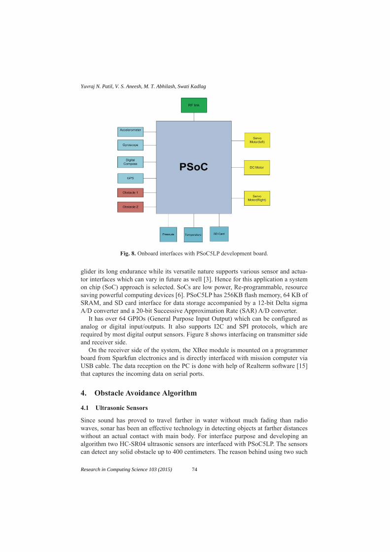
Fig. 8. Onboard interfaces with PSoC5LP development board.
glider its long endurance while its versatile nature supports various sensor and actua-tor interfaces which can vary in future as well [3]. Hence for this application a systemon chip (SoC) approach is selected. SoCs are low power, Re-programmable, resourcesaving powerful computing devices [6]. PSoC5LP has 256KB flash memory, 64 KB ofSRAM, and SD card interface for data storage accompanied by a 12-bit Delta sigmaA/D converter and a 20-bit Successive Approximation Rate (SAR) A/D converter.
It has over 64 GPIOs (General Purpose Input Output) which can be configured asanalog or digital input/outputs. It also supports I2C and SPI protocols, which arerequired by most digital output sensors. Figure 8 shows interfacing on transmitter sideand receiver side.
On the receiver side of the system, the XBee module is mounted on a programmerboard from Sparkfun electronics and is directly interfaced with mission computer viaUSB cable. The data reception on the PC is done with help of Realterm software [15]that captures the incoming data on serial ports.
4. Obstacle Avoidance Algorithm
4.1 Ultrasonic Sensors
Since sound has proved to travel farther in water without much fading than radiowaves, sonar has been an effective technology in detecting objects at farther distanceswithout an actual contact with main body. For interface purpose and developing analgorithm two HC-SR04 ultrasonic sensors are interfaced with PSoC5LP. The sensorscan detect any solid obstacle up to 400 centimeters. The reason behind using two such
74
Yuvraj N. Patil, V. S. Aneesh, M. T. Abhilash, Swati Kadlag
Research in Computing Science 103 (2015)

sensors is that the glider should not consider a small fish or some junk sinking in thewater as an obstacle. By comparing both sensors the PSoC5LP can determine whetheror not the obstacle is large enough to change motion of the glider, these sensors condetect obstacle from 0 degrees to 15 degrees. So they can be placed on both wings orin the nose of the glider to cover required area.
4.2 Interfacig
Two HC-SR04 ultrasonic sensors are interfaced with PSoC5LP and placed at a distanceof 3 cm from each other for demonstration purpose.
Fig. 9. Two ultrasonic sensors interfaced with PSoC5LP.
On the actual glider, they can be placed on both wings to cover more area and betterobstacle detection. The sensors are PWM type and needs a trigger of 10 micro secondsafter which they send out 8 pulses of 40kHz and then weight for an echo. A counter runsfor that amount of time till the echo pulse is received. Both the sensors give almost samedistance with offset of 1 cm. The distance is calculated based on following equations.
(1)
There will be some noise present in the received echo but can be easily dealt byapplying certain threshold. Complex filters are not required since there purpose ofthese sensors is just to detect an obstacle and not to map an entire terrain.
The algorithm is for obstacle avoidance applied for the central buoyancy tank sincethis is the tank that would be responsible for the saw tooth motion of the glider. As thewater is being drawn into the tank, the glider is going down. If the obstacle is detected,the piston motion is reversed so as to push the water out as a result the glider startsupward motion before reaching its predefined depth to avoid the obstacle. The AUGcentral piston and tank is imitated by a 100ml surgical syringe operated by rack andpinion mounted on a wooden platform. Since this is a prototype used for simulationpurpose and developing an algorithm, the dimensions and design parameters thatwould suit actual glider are neglected at this moment. The displacement of the rack isgiven by following formula:
(2)x r= 2 P Q
Range echotime velocity of sor=
¥2
75
Electronic System for Orientation Control and Obstacle Avoidance for Underwater Glider ...
Research in Computing Science 103 (2015)

where,x is the displacement of rack,r is the radius of pinion,Θ is the angle of rotation of pinion.
Fig. 10 & 11. DSO showing echo received by sensor after triggering, Desired obstacle avoid-ance in saw toot motion.
Fig. 12. Flowchart for obstacle avoidance system.
The DC motor is turned clockwise for a duration of 5 seconds which is enough topull the piston by full length of the cylinder. A short delay is of 2 sec. is introduced afterwhich the motor goes in anti-clockwise direction. This pushes the piston back in its ini-tial state depicting the surfacing action of the glider. The delay depends upon the counterbeing incremented per iterations which selected based on experimental observations.
A feedback is taken from ultrasonic sensors all the time to check for any obstacle.In case of an obstacle, the rotation of the motor is reversed.
76
Yuvraj N. Patil, V. S. Aneesh, M. T. Abhilash, Swati Kadlag
Research in Computing Science 103 (2015)

This stops the glider from achieving predefined altitude and the glider willchange its upward or downward motion. The glider does not steer itself in order toavoid obstacle hence the steering mechanism is independent of the obstacle avoid-ance system. Above is a flowchart of the algorithm for the obstacle avoidancesystem.
5. Orientation Control Algorithm
Many of the existing gliders that are designed rely on either rudder or movable inter-nal mass to change its course. Assuming unavailability of the rudder on a glider andmovable solid internal mass, a 3 cylinder mechanism is proposed to be used. The pis-tons of side cylinders are operated by two VS-2 servo motors. The motor shaft is con-nected to rack and pinion mechanisms that drive the pistons. The servo motors arePWM signal driven and their angle shift for respective compare values is shown in fol-lowing diagram. The system clock for the PWM block in PSoC creator 3.0 is set at2MHz. and the period is kept 20 micro seconds. The angle will depend upon the com-pare value which is nothing but the duty cycle of PWM pulse. The pulse width is var-ied in order to change the duty cycle.
Fig. 13 & 14. PWM for minimum angle of servo motor for piston at initial position (no water intank), PWM for maximum angle of servo motor for piston at final position (water in tank).
At 1.53ms of the pulse width, the angle of rotation of the servo motor is closeto 0 degrees. On powering on the system, this is the default PWM pulse widthgiven to the servo motor. At 2.40ms of the pulse width the angle of rotation of theservo motor is close to +90 degrees. The on time for pulse tends to increase fur-ther on more deviation but would not result in servo motor’s angle change beyond+90 degrees.
For understanding the concept behind the steering control, the angle of rotation ofservo motor is kept directly proportional to the change in the difference of yaw anglefrom glider’s initial approach vector. i.e. minimum the angle of deviation from mainpath lesser will the water allowed to fill up the tank and vice versa. This would result
77
Electronic System for Orientation Control and Obstacle Avoidance for Underwater Glider ...
Research in Computing Science 103 (2015)

in steering of the glider and compensating motion for unwanted shift in the course ofthe glider A feedback is taken from digital compass and the gyroscope. The comparevalue of PWM required to drive servo motor by –90 degrees is 600 and for +90degrees is 2400. The equations for mapping the difference in yaw angle with thecompare value are.
(3)
This compare value is nothing but the pulse width that needs to be varied for thePWM signal to get desired angle on servo motor. The flowchart of the algorithm isshown in Figure 15.
The digital compass is a HMC5883L with i2c interface working on 2.6V-3.6V. Thesensitivity of this digital compass is 2 milli-gauss Field Resolution in ±8 Gauss Fields.As the digital compass may read any value while dropping the glider, depending uponthe direction at that moment the reading is recorded and stored in a temporary variable.This variable is stored as a reference for further computing. The PSoC keeps readingits new heading direction and compares its current reading with this stored value. Thecurrent reading is subtracted from the stored value and the difference is noted.Depending upon positive or negative value of the difference, the deviation in left orright direction is determined. Same is done by using a digital gyroscope. The differ-ence in the angle is calculated and compared with the digital compass readings.
The algorithm is implemented on piston mechanisms mounted on a wooden plat-form. Figure 18 shows actual demonstration board with cylinders mounted with rackand pinions driven by servo motors and DC motor.
map difference
Compare value difference in( ,min,max, , )(
600 2400
=yyaw
Compare value difference i
+ÊËÁ
ˆ¯̃
¥ - +
=
90180
2400 600 600) ( )
[( nn yaw + +90 10 600)]
Fig. 15. Flowchart for orientation control using feedback from sensors.
78
Yuvraj N. Patil, V. S. Aneesh, M. T. Abhilash, Swati Kadlag
Research in Computing Science 103 (2015)
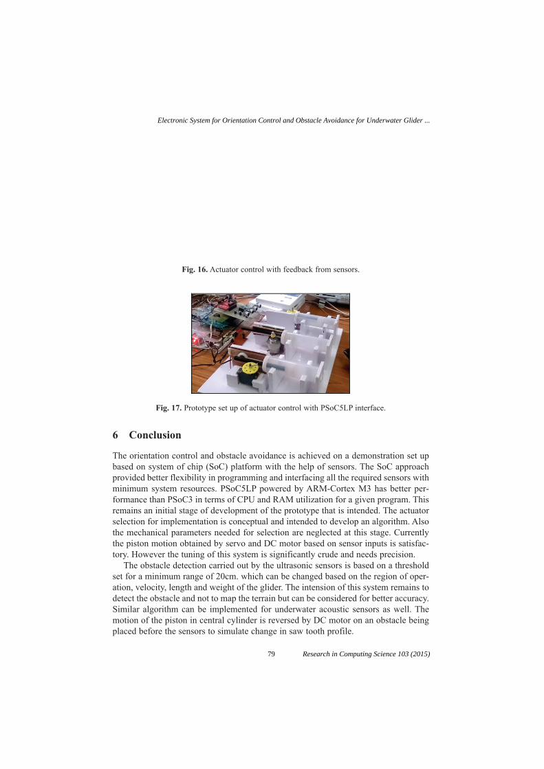
6 Conclusion
The orientation control and obstacle avoidance is achieved on a demonstration set upbased on system of chip (SoC) platform with the help of sensors. The SoC approachprovided better flexibility in programming and interfacing all the required sensors withminimum system resources. PSoC5LP powered by ARM-Cortex M3 has better per-formance than PSoC3 in terms of CPU and RAM utilization for a given program. Thisremains an initial stage of development of the prototype that is intended. The actuatorselection for implementation is conceptual and intended to develop an algorithm. Alsothe mechanical parameters needed for selection are neglected at this stage. Currentlythe piston motion obtained by servo and DC motor based on sensor inputs is satisfac-tory. However the tuning of this system is significantly crude and needs precision.
The obstacle detection carried out by the ultrasonic sensors is based on a thresholdset for a minimum range of 20cm. which can be changed based on the region of oper-ation, velocity, length and weight of the glider. The intension of this system remains todetect the obstacle and not to map the terrain but can be considered for better accuracy.Similar algorithm can be implemented for underwater acoustic sensors as well. Themotion of the piston in central cylinder is reversed by DC motor on an obstacle beingplaced before the sensors to simulate change in saw tooth profile.
Fig. 16. Actuator control with feedback from sensors.
Fig. 17. Prototype set up of actuator control with PSoC5LP interface.
79
Electronic System for Orientation Control and Obstacle Avoidance for Underwater Glider ...
Research in Computing Science 103 (2015)

For orientation control, the min. and max. angles of servo motor drive the piston byits full length inside the cylinders. The difference in angles of heading vectors obtainedfrom the orientation sensors is linearly proportional to the angle of rotation of bothservo motors.
Acknowledgement
We would like to take this opportunity to express our heartiest gratitude to DIAT-DRDO(DU) Pune, and to all its students and faculty members of ElectronicsEngineering Department, Naval Wing, Navigation department, aerospace dpt. of DIAT-DRDO(DU) for their valuable suggestions and support throughout this work. We alsothank Symbiosis Institute of Technology, Pune for providing valuable guidance andnecessary facilities throughout the process.
References
1. Amit Ray, Singh S.N. and Seshadri V, ‘Underwater Gliders – Force Multipliers for NavalRoles’ at the RINA conference ‘Warship 2011 : Naval Submarines and UUVs’, 29-30 June,2011 at the Guildhall, Bath, UK. William P Barker, ‘Analysis of undersea glider architec-tures and an assessment of undersea glider integration for undersea applications’, Sep 12.
2. Danio Joe, R V Shashank Shankar, RVijay kumar and Arnab Das, ‘Concept Design ofAutonomous Underwater Glider.
3. Arnab Das, “Naval Operations Analysis in the Indian Ocean Region-A Review”, Acceptedfor publication in the IDSA Journal.
4. Russ E. Davis, Charles C.Eriksen, Clayton P. Jones. “Autonomous Buoyancy-drivenUnderwater gliders”.The technology and application of autonomous underwater vehicles,G.Griffiths,ed.,Taylor and Fransis, London 2002.
5. Charles C. Eriksen, T. James Osse, Russell D. Light, Timothy Wen, Thomas W. Lehman,Peter L. Sabin, John W. Ballard, and Andrew M. Chiodi Seaglider: A Long-RangeAutonomous Underwater Vehicle for Oceanographic Research, IEEE Journal of oceanicEngineering, Vol. 26, No. 4, Oct 2001.
6. Stephen Bozzone, Brian Newberry, Dominic Germana Enhancements and Performance ofSeaglider Iridium Communications System Chris Yahnker,OCEANS,2012.
7. Abdallah Ismail, Project report on Programmable System-on-Chip technology from CypressSemiconductor digital systems architecture, Dec 2007.
8. M.D. Nair, Abhilash M.T., Vijay Kumar, Arnab Das “Embedded control system for under-water glider based on PSoC” et al International Journal of Computer and ElectronicsResearch, Volume 3, Issue 2, April 2014
9. Jeff Sherman, Russ E. Davis, W. B. Owens, and J. Valdes, “The Autonomous UnderwaterGlider Spray” IEEE JOURNAL OF OCEANIC ENGINEERING, VOL. 26, NO. 4, OCTO-BER 2001.
10. Luke Stutters, Honghai Liu Senior Member, IEEE, Carl Tiltman and David JBrown,”Navigation Technologies for Autonomous Underwater Vehicles”,IEEE TRANSAC-TIONS ON SYSTEMS, MAN AND CYBERNETICS - PART C: APPLICATIONS ANDREVIEWS, VOL. 38, NO. 4, JULY 2008.
11. R. E. Davis, “Preliminary results from directly measuring middepth circulation in the tropi-cal and South Pacific,” J. Geophys. Res., vol. 103, pp. 24 619–24 639, 1998.
80
Yuvraj N. Patil, V. S. Aneesh, M. T. Abhilash, Swati Kadlag
Research in Computing Science 103 (2015)

12. M. J. McPhaden, “Genesis and evolution of the 1997–98 El Nino,” Science, vol. 283, pp.950–954, 1999.
13. S. A. Jenkins and J. Wasyl, “Optimization of glides for constant wind fields and course head-ings,” J. Aircraft, vol. 27, pp. 632–638, 1990.
14. http://www.mtu.edu/engineering/15. http://realterm.sourceforge.net/
81
Electronic System for Orientation Control and Obstacle Avoidance for Underwater Glider ...
Research in Computing Science 103 (2015)


Accuracy of Artificial Neural Network Models ofSoftware Reliability Growth – A Survey
M. K. Saley1 and Sasikumaran Sreedharan2
1Research Scholar, ManonmaniamSundaranar University,Thirunelveli, India
[email protected] of Computer Engineering,
King Khalid University, [email protected]
Abstract: Software Engineering data is being analyzed by classical statisticalmethods and non parametric methods. Performance models are constructed usingclassical approach as a high maturity practice. Such practices are constrained bydata quality and inadequacy of data analysis methods to treat data from real lifeprojects. Data mining techniques can broaden the data analysis capability andimprove prediction accuracy even with commonly presented data. Artificial neuralnetworks are found as an improved prediction error estimation method against tra-ditional parametric software reliability growth models. In this paper, we study pre-diction errors of Artificial Neural Networks (ANN) based Software ReliabilityGrowth Models (ANN SRGM) with the objective of arriving at a criteria for select-ing the methods having least prediction errors. All major works in ANN SRGM’sare considered and reported errors are analyzed. Accuracy of ANN SRGM’s arecompared against that of parametric models. Then, inter-comparison of error per-formances of ANN SRGM’s of different applications is made.
Keywords: Software Reliability Growth Model, Artificial Neural Networks,Prediction Accuracy, Root Mean Square Error of ANN, Learning Speed of ANN,Flexibility of ANN.
1 Introduction
Various attempts are being made to apply Artificial Neural Networks (ANN) to substi-tute traditional parametric Software Reliability Growth Models (SRGM). A new breedof ANN based SRGM’s have been introduced by researchers in this field. While para-metric models give clues to process composition and behavior, the nonparametric ANNSRGM’s offer greater accuracy and flexibility [1].
Typical software reliability data consists of cumulative defects discovered duringtesting. The pattern may vary depending on how early defects are discovered, howpromptly defects are reported, and how well testing process is planned. Because ofthese reasons data patterns vary from organization to organization, from project to
83 Research in Computing Science 103 (2015)pp. 83–91; rec. 2015-06-03; acc. 2015-06-20

project. Reliability growth is concerned with the pattern by which defect discoveryprogresses towards the ideal plateau region of defect free state. This is a time seriesproblem and to study reliability growth models, one does not consider software struc-ture or software development process composition. It is a black box view on defect dis-covery pattern. Parametric models use mathematical equations that may use testengineering parameters like test efficiency, test effort, software size, review speed etc;such models, when constructed, provide insight into what is happening during testing.ANN SRGM’s do not aim at obtaining such an insight; in fact they are incapable ofseeing the hidden factors of structural aspects. The purpose of ANN SRGM is to learnfrom data patterns and predict pending defects.
The inability of ANN SRGM to provide insight into problem structure is richlycompensated by the greater prediction accuracy, which emerges as the most importantcriteria by which we can judge the performance of ANN SRGM’s. In this paper, weconsider the pioneering work done by several researchers and study the results reportedby them, providing an inter-comparison of errors.
2 Comparison of Performance of Parametric Modelswith ANN SRGM
The key question that concerns users of Artificial Neural Network Software ReliabilityGrowth Models (ANN SRGM) is whether the proposed ANN SRGM will provide bet-ter accuracy than existing parametric models such as Goel-Okumoto Model, DelayedS Model, Logarithmic Model, Exponential Model, Power Model, and InversePolynomial Model. Every researcher who has proposed ANN SRGM has answered thisquestion in favor of ANN SRGM. [2] Comments and conclusions such as “ANN pro-vides better results” are common. Such conclusions are not objective enough.
Hypothesis Test 1. The first objective error data comparing ANN with parametricmodels has come from Karunanidhi [3] and is summarized in Table 1. The error met-ric data Average Error (AE) % has been selected and used to construct Table 1.
Five parametric models and six ANN SRGM’s are considered in Table 1. Error datais provided for each model against three data sets. On this data, a hypothesis test has
Table 1. End Point Error from Karunanidhi’s Data [3].
������� ���� ���� � ���� � ���� ���������� ������ �� ����� ���� �������������� ������� ���� ��� �������������� ��� ����� ����� �������������� ����� ����� ����� �������������� �������� ����� ����� ����
��� �������� ����� ����� �!����� ���� ����� ����� ������� ����� ���� ���� �!������ � ���� ���� �������� "��������� ��!� ���� ������� "������� ���� ���� ����
�� �
84
M. K. Saley, Sasikumaran Sreedharan
Research in Computing Science 103 (2015)

been done by the authors to see if ANN SRGMs fare better than parametric models. Agroup is formed with error data for six ANN SRGMs and three data sets with a total ofeighteen data points. Another group is formed with error data for the five parametricmodels and three data sets, with a total of fifteen data points. A t-Test has been doneon the two groups of data and the results are shown in Table 2.
The mean values of average errors are 10.91 and 16.8 for ANN and parametric mod-els, clearly showing an improvement of 5.90 in the mean. This is good enough in normalsituations to go in for ANN; however, in the light of skepticism and criticism that prevailupon ANN a more stringent judgment is called for. The t - Test p value provides thisinformation and is only 0.061. Had the p value been less than 0.5 we could have acknowl-edged, by a popular rule, significant improvement. With a borderline value of 0.061,ANN experiments have not yet delivered convincing results with statistical significance.
In addition to the t Test, a visual comparison of the two error data groups has beendone using Turkey’s box plot as shown in Fig. 1. The most common form of the box plotis constructed with median value at the center line and, quartiles in the box edges andwhiskers that stretch from the box to connect with the extreme values. The box plot offersa more robust comparison, compared to a t-Test, and is not dependent on data normality.
Hypothesis Test 2. Karunanidhi’s data is typical of ANN performance. Many otherresearchers support the view that ANN is better than parametric models. There havebeen many results reported in clear support of ANN. Sultan’s data [4] is an example ofresults that are not so convincing. Sultan uses Summed Square Error (SSE), as the errormetric and considers three types of projects, shown in Table 3.
A t-Test done on Sultan’s data is shown in Table 4. The mean SSE values are 57.2and 60.3 for ANN and Parametric Models. ANN scores better, with less mean error.The difference is only marginal. But the p value is 0.970 which suggests that ANN has
Table 2. Two Sample t –Test Results on difference in AE % betweenANN SRGM and Parametric Models.
Hypothesis Testing T-Test of difference = 0 (vs �)
MODEL N AE % Mean
AE % StDev
SE Mean
ANN SRGM 18 10.91 8.99 2.1 PARAMETRIC MODEL
15 16.80 8.38 2.2
Difference � (ANN) - � (PARAMETRIC) Estimate for difference -5.90 95% CI for difference (-12.08, 0.29) T-Value -1.95P-Value 0.061Degrees of Freedom 30
Table 3. Test Errors from Sultan’s Data [4].
SUM SQUARE ERROR PROJECT PARAMETRIC ANN Military 168.54 160.3887Real Time Control 1.368 1.2542 Operating System 10.885 9.9623
85
Accuracy of Artificial Neural Network Models of Software Reliability Growth ...
Research in Computing Science 103 (2015)

not produced significantly different results from Parametric Models. With such a highp value, one would tend to consider them equal.
This is a clear example of a situation where ANN performance is equal to paramet-ric model performance, but offers an advantage, though small.
3 Sensitivity of End Point Errors to Data Patterns –A Hypothesis Test
A limitation of ANN SRGM arises out of its difficulty to cope up with changes in datapatterns. Its ability to forecast depends on smoothness of training data. Typically thedata is the cumulative defects found during testing and its pattern can vary from proj-ect to project, depending on the quality of testing and management of testing process.There could be sudden jumps and micro plateaus; the inflexion point could change ifproportion of early discovery changes. The finishing line flatness could also changedepending on test case effectiveness. ANN SRGM trained with such turbulent patternsmay show larger errors during testing. Also, it has been shown that the number of hid-den nodes required for optimum errors vary if the data set changes [5]. As a result soft-ware reliability data sets and the actual patterns of data seem to have an influence onANN SRGM prediction errors (end point errors).
Sultan’s [4] results, shown in Table 3, exhibits dramatic variation of SSE when dataset changes. SSE could vary from a value as low as 1.25 in one project dataset to avalue as high as 160.39 in another project dataset. The change is so dramatic and obvi-ous that without using a sophisticated hypothesis testing one can arrive at the judg-ment. The problem exists even with parametric models. Basically ANN SRGM has notsolved a fundamental problem: reliability models fail to show consistent performanceacross datasets. If data patterns could dictate errors so much, it is not good news forthose who wish switch over to ANN SRGM’s, because they do not see any advantagein doing so, from the point of view of data-pattern sensitive performance.
Adifferent situation emerges if we examine Karunanidhi’s data shown in Table 1. To testthis hypothesis that data sets control errors, Analysis of Variance (ANOVA) has been doneon ANN SRGM AE % for three different data sets. ANOVA results are shown in Table 5.
Table 4. t -Test Results on Squared Sum of Error difference betweenParametric and ANN SRGM.
Hypothesis Testing T-Test of difference = 0 (vs �)
MODEL N AE % Mean
AE % StDev
SE Mean
ANN SRGM 3 57.2 89.5 52 PARAMETRIC MODEL
3 60.3 93.9 54
Difference � (ANN) - � (PARAMETRIC) Estimate for difference -3.1 95% CI for difference (-241.4, 235.2) T-Value -0.04P-Value 0.970Degrees of Freedom 3
86
M. K. Saley, Sasikumaran Sreedharan
Research in Computing Science 103 (2015)

The p value is 0.306, indicating that data sets do not have significant influence on errors.This means that ANN SRGMs have overcome the problem of data-pattern sensitivity.
4 Inter-comparison of Prediction Errors of ANN SRGM’S
Normalized Data. Prediction errors in six experiments with ANN Software ReliabilityGrowth Models performed from 1992 till 2013 by various researchers have been com-piled and shown in Table 6. The error metric selected for this inter-comparison is AE %
Table 5. ANOVA Results of Dataset Sensitivity of Errors.
Hypothesis Testing: ANOVA
Source DF Adj SS Adj MS F-Value P-Value
DATA 2 200.7 100.33 1.28 0.306 Error 15 1174.7 78.31 - -Total 17 1375.4 - - -
Table 6. Normalized Data of ANN SRGM Test Errors.
NORMALIZED DATA OF PREDICTION ACCURACY OF ANN SRGM
Ref.No Name of the Author Year published
Name of NN AE %
[3]NachimuthuKarunanidhi, Darrel Whitley and Yaswant K. Malaiya.
1992
FFN GEN ENC DS1
26.7500
FFN GEN ENC DS2
14.5100
ELMAN DS1 24.7300 ELMAN DS2 13.2400 FFN GEN DS1 6.6300FFN GEN DS2 3.5200 FFN DS1 3.7600 FFN DS2 2.3200 FFN DS3 12.3200 JORDAN GEN DS1
3.0500
JORDAN GEN DS2
3.1100
JORDAN DS1 2.6800 JORDAN DS2 3.2100
[7] NachimuthuKarunanidhi, Darrell Whitley and Yaswant
1992
FFN generalization 0.0667 FFN prediction 0.0612 JN generalization 0.0475 JN prediction 0.0494
[5] Jun Zheng 2009
PSNN 1 1.890 PSNN 2 4.650 PNNE 1 1.290 PNNE 2 1.630
[10] Jung-Hua Lo 2009
MLFFN 1 20.790 MLFFN 2 7.350 MLFFN 3 8.900 MLFFN 4 2.260
[11] Yogesh Singh, Pradeep Kumar
2010
FFNW 1 0.100 FFNW 2 0.050 FFNW 3 0.120 FFNW 4 0.340 FFNW 5 0.830
[12] Rita G. Al gargoor, Nada N Saleem
2013 PSO 7.180PSO 6.090PSO 4.480
87
Accuracy of Artificial Neural Network Models of Software Reliability Growth ...
Research in Computing Science 103 (2015)
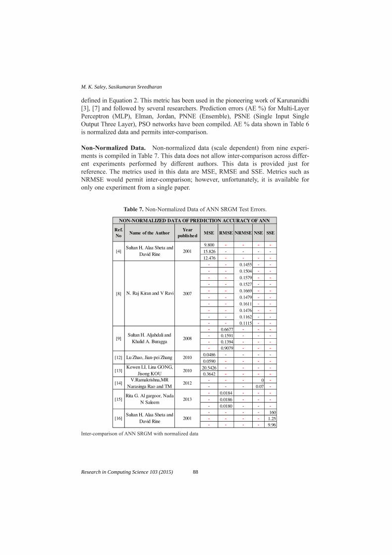
defined in Equation 2. This metric has been used in the pioneering work of Karunanidhi[3], [7] and followed by several researchers. Prediction errors (AE %) for Multi-LayerPerceptron (MLP), Elman, Jordan, PNNE (Ensemble), PSNE (Single Input SingleOutput Three Layer), PSO networks have been compiled. AE % data shown in Table 6is normalized data and permits inter-comparison.
Non-Normalized Data. Non-normalized data (scale dependent) from nine experi-ments is compiled in Table 7. This data does not allow inter-comparison across differ-ent experiments performed by different authors. This data is provided just forreference. The metrics used in this data are MSE, RMSE and SSE. Metrics such asNRMSE would permit inter-comparison; however, unfortunately, it is available foronly one experiment from a single paper.
Table 7. Non-Normalized Data of ANN SRGM Test Errors.
Ref.No
Name of the AuthorYear
publishedMSE RMSE NRMSE NSE SSE
9.800 - - - -
15.826 - - - -
12.476 - - - -- - 0.1455 - -- - 0.1504 - -- - 0.1579 - -- - 0.1527 - -- - 0.1669 - -- - 0.1479 - -- - 0.1611 - -- - 0.1476 - -- - 0.1162 - -- - 0.1115 - -- 0.6677 - - -- 0.1591 - - -- 0.1394 - - -- 0.9079 - - -
0.0486 - - - -
0.0590 - - - -
20.5426 - - - -0.3642 - - - -
- - - 0 -- - - 0.07 -- 0.0184 - - -- 0.0186 - - -- 0.0180 - - -- - - - 160- - - - 1.25- - - - 9.96
[15]Rita G. Al gargoor, Nada
N Saleem2013
[16]Sultan H, Alaa Sheta and
David Rine2001
[13]Kewen LI, Lina GONG,
Jisong KOU2010
[14]V.Ramakrishna,MR
Narasinga Rao and TM 2012
[9]Sultan H. Aljahdali and
Khalid A. Buragga2008
[12] Lu Zhao, Jian-pei Zhang 2010
NON-NORMALIZED DATA OF PREDICTION ACCURACY OF ANN
[4]Sultan H, Alaa Sheta and
David Rine2001
[8] N. Raj Kiran and V Ravi 2007
Inter-comparison of ANN SRGM with normalized data
88
M. K. Saley, Sasikumaran Sreedharan
Research in Computing Science 103 (2015)
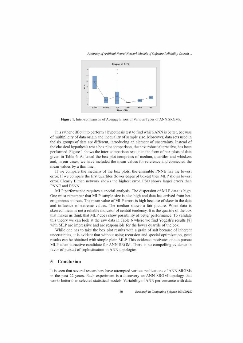
It is rather difficult to perform a hypothesis test to find which ANN is better, becauseof multiplicity of data origin and inequality of sample size. Moreover, data sets used inthe six groups of data are different, introducing an element of uncertainty. Instead ofthe classical hypothesis test a box plot comparison, the next robust alternative, has beenperformed. Figure 1 shows the inter-comparison results in the form of box plots of datagiven in Table 6. As usual the box plot comprises of median, quartiles and whiskersand, in our cases, we have included the mean values for reference and connected themean values by a thin line.
If we compare the medians of the box plots, the ensemble PNNE has the lowesterror. If we compare the first quartiles (lower edges of boxes) then MLP shows lowesterror. Clearly Elman network shows the highest error. PSO shows larger errors thanPNNE and PSNN.
MLP performance requires a special analysis. The dispersion of MLP data is high.One must remember that MLP sample size is also high and data has arrived from het-erogeneous sources. The mean value of MLP errors is high because of skew in the dataand influence of extreme values. The median shows a fair picture. When data isskewed, mean is not a reliable indicator of central tendency. It is the quartile of the boxthat makes us think that MLP does show possibility of better performance. To validatethis theory we can look at the raw data in Table 6 where we find Yogesh’s results [8]with MLP are impressive and are responsible for the lower quartile of the box.
While one has to take the box plot results with a grain of salt because of inherentuncertainties, it is evident that without using recursion and special optimization, geedresults can be obtained with simple plain MLP. This evidence motivates one to pursueMLP as an attractive candidate for ANN SRGM. There is no compelling evidence infavor of pursuit of sophistication in ANN topologies.
5 Conclusion
It is seen that several researchers have attempted various realizations of ANN SRGMsin the past 22 years. Each experiment is a discovery an ANN SRGM topology thatworks better than selected statistical models. Variability of ANN performance with data
�����������������������
�
��
��
��
��
�
�
����������
����
���������������
Figure 1. Inter-comparison of Average Errors of Various Types of ANN SRGMs.
89
Accuracy of Artificial Neural Network Models of Software Reliability Growth ...
Research in Computing Science 103 (2015)

sets is a concern. Inadequate attention to characteristics of trained networks leavesANN less trustworthy in the critical eyes of ANN users. It is noted that input datapreparation and structuring extend ANN performance to greater levels. Further refine-ment is obtained by the choice of judicious activation functions that resemble theempirical data patterns
This survey finds ANN SRGM is better than statistical models for reliability pre-diction. However, the statistical significance of results is still low, with a p value of0.61, leaving a wide scope for further research and improvement in ANN SRGM. Theerrors are comparable and in some cases better than errors achieved in other domains.
References
1. Saley M.K and SasikumaranSreedharan, “A Survey of Software Reliability Growth ModelsUsing Non-Parametric Methods”, IEEE International Conference on ComputationalIntelligence and Computing research”, Dec. 2014.
2. Doteswamy and Chanabasayya M Vastrad, “Performance Analysis of Oxazolens andOxazoles Derivatives Description Dataset”, Vol 03, No 6, International Journal ofInformation Sciences and Techniques, Nov 2013.
3. NachimuthuKarunanidhi, Darrel Whitley and Yaswant K. Malaiya., “Prediction of reliabil-ity model using Connectionist Models,” IEEE transactions on software engineering, Vol. 18,No. 7, July 1992. pp. 563–574.
4. Sultan H, AlaaSheta and David Rine, “Prediction of Software Reliability: A comparisonbetween Regression and Neural Network Non-Parametric Models,” Computer Systems andApplications, ACS/IEEE International Conference, pp. 470–473, June 2001.
5. Jun Zheng, “Predicting software reliability with neural network ensembles”, ELSEVIER,Expert Systems with Applications 36, 2116–2122, 2009.
6. ZhigangGan, Nanfeng Xiao, “An Improved Adaptive Boosting Algorithm for NeuralNetwork Ensemble Based on Multi-dimensional Cloud Model”, Second InternationalSymposium on Knowledge Acquisition and Modeling, IEEE Computer Society, 2009.
7. NachimuthuKarunanidhi, Darrell Whitley and Yaswant, “Using Neural Networks inReliability Prediction,” IEEE software, 0740-7459/92/0700/0053, July 1992.
8. N. Raj Kiran and V Ravi, “Software Reliability Prediction Using Wavelet Neural Networks”,IEEE computer society, pp.195–199, 2007.
9. Sultan Aljahdali and Alaa F sheta, “Predicting the Reliability of software System usingFuzzy Logic”, IEEE 2011.
10. Jung-Hua Lo “The Implementation of Artificial Neural Networks Applying to SoftwareReliability Modeling”, IEEE Chinese Control Decision Conference, 2009.
11. Yogesh Singh and Pradeep Kumar, “Prediction of software reliability Using Feed ForwardNeural Networks” Computational Intelligence and Software Engineering (CiSE),International Conference, 2010.
12. Lu Zhao, Jian-pei Zhang et al., “Software reliability Growth Model based on Fuzzy WaveletNeural network”, IEEE 2nd International Conference on Future Computer andCommunication, Vol. 1, pp. VI 664–VI 668, 2010
13. Kewen LI, Lina GONG, Jisong KOU, “Predicting Software Quality by Fuzzy NeuralNetwork Based in Rough Set”, Journal of Computational Information systems,pp. 1439–148, May 2010.
90
M. K. Saley, Sasikumaran Sreedharan
Research in Computing Science 103 (2015)

14. V.Ramakrishna,MRNarasingaRao and TM Padmaja “Software reliability prediction usingNeural Networks”, International journal of Computer Applications(0975 – 887) Vol. 60-No.&, December 2012.
15. Rita G. Al gargoor, Nada N Saleem, “Software Reliability Prediction Using ArtificialTechniques”, IJCSI International Journal of Computer Science Issues, Vol. 10, Issue 4,No. 2, ISSN (Print): 1694-0814, pp. 274–281, July 2013.
16. Sultan H, AlaaShetta, David Rine, “Prediction of Software Reliability: A comparisonbetween Regression and Neural Network Non-Parametric Models,” Computer Systems andApplications, ACS/IEEE International Conference, pp. 470–473, June 2001.
17. G.Q. Shang, C.H Sun, “Application of BP Neural Network for Predicting Anode Accuracyin ECM”, International Symposium on Information Science and Engineering, IEEEComputer Society 2008. pp. 428–432.
18. Qi Feng, Shengjun Wu, Yun Du, HuaipingnXue, Fei Xiao Ban, and Xiaodong Li,“Improving Neural network Prediction Accuracy for PM Individual Air Quality IndexPollution Levels”, Environmental Engineering Science, Volume 30, 2013.
19. Lihua Chen, Yuchen Wang, “Application of Radial Basis Function Neural Network on thePrediction of Urban Built-up Area”, Applied Mechanics and Materials, Trans techPublications, Switzerland, Vols. 556–562, pp. 5308–5311. 2014.
20. Di Lu and Jing Liu, “Application of Improved Neural Network in the Automotive EngineFault Diagnosis”, International journal of Control and Application, Vol. 7, No. 4, pp. 262–355,2014.
21. Fuqiang Zhou, Zhen Su, Xinghua Chai and Lipeng Chen, “Detection of Foregin Matter inTransfusion Solution Based on Gaussian Background Modeling and an Optimized BPNeural Network”, Sensors ISSN 1424-8220, 2014.
22. A. Noriega, D Blanco, B.J. Alvarez, A.Garcia, “Dimensional Accuracy improvement ofFDM square cross-section parts using artificial neural networks and an optimization algo-rithm”, Int J Adv Manuf Technol, Springer, 2013.
23. Kunwar Singh Vaisla and Ashuthosh Kumar Bhatt, “An Analysis of the Performance ofArtificial Neural Network Technique for Stock Market Forecasting”, Vol 02, No. 06,International Journal on Computer Science and Engineering, 2010.
91
Accuracy of Artificial Neural Network Models of Software Reliability Growth ...
Research in Computing Science 103 (2015)

Development of Dual-Actuated Stage for PositioningApplications
Prabha Niranjan1, K. V. S. S. S. S. Sairam1, Shashikantha Karinka2
1Department of Electronics and Communication Engineering,2Department of Mechanical Engineering,
NMAMIT, [email protected]
Abstract. Piezoelectric actuators have been widely used in precision positioningapplications because of their fast response, fine resolution, and large actuatingforces. The displacement of piezoelectric actuators should be precisely controlledto use them in precision actuation stages. However to use these piezoelectric actu-ators in control systems, it is very much necessary to estimate the displacement ofactuator based on their input voltage and also the inverse model. This paper pres-ents Prandtl-Ishlinskii model for describing the nonlinearity of the actuator. InversePrandtl-Ishlinskii model will be used in the feed forward loop for the compensationof nonlinearity. This research work also includes development of a dual-actuatedsingle stage to overcome the small travel range of piezoelectric stack actuators. Thepiezoelectric stack actuator is used for fine positioning and ball screw actuator isused for coarse positioning in the proposed dual-actuated stage. A closed loop con-trol will be designed for the dual positioning stage, and this stage will be laterapplied for real-time wing flap control of aircraft model.
Keywords: Piezoelectric actuator; Prandtl-Ishlinskii model; Positioning; Closedloop control system; Displacement; Dual-Stage; Ball screw actuator.
1 Introduction
In recent years, there is lot of scope for research in ultra precision positioning applica-tions. It includes diamond cutting, drilling machine, wing flap control in aircraft etc.Such ultra precision position systems require displacement control in the range ofmicrometers to millimeters.
In ultra-precision positioning, the piezoelectric actuators are used because of theirgood dynamic response and high resolution. It can be used for nano-positioning drivesbut it is bit tedious to provide higher load capacity. Whereas ball screw provides higherload capacity and stiffness but it fails in providing accuracy in sub-micrometer range[1],[2].
Hence for high precision machines, dual positioning systems have been developedwhere piezoelectric actuator is used for fine positioning and ball screw actuator is usedfor coarse positioning [3], [4], [5].
93 Research in Computing Science 103 (2015)pp. 93–98; rec. 2015-06-03; acc. 2015-06-20

In this paper, the various hysteresis models are discussed in section 2. The simula-tion model of piezoelectric actuator is presented in section 3. The proposed dual-actu-ated single stage for positioning applications is given in section 4, followed byconclusion and future work.
2 Hysteresis Modeling
Piezoelectric actuators (PEAs) are widely used in variety of positioning applicationsdue to their advantages of high positioning resolution in the range of micrometers tonanometers, large force, high dynamic response, high stiffness and compact design [6],[7], [8]. The major drawback of the PEA is its hysteresis nonlinearity that leads to posi-tioning inaccuracy, and even instability of closed loop systems [9]. In order to increasethe positioning accuracy of the PEA, there is a need to model the PEA, taking into con-sideration hysteresis and creep nonlinearities, which otherwise lead to large errors.
The various mathematical models which are popularly used to describe the hystere-sis phenomenon like Preisach model, Prandtl-Ishlinskii (PI) model, Maxwell-slipmodel, etc. are proposed by various researchers [10].
In Preisach model, much of data is required to characterize the nonlinear systemsthat will influence the accuracy of the model. Obtaining inverse model is not easy inthis type due to double integral present in the equation [11],[12],[13].
Maxwell-slip model operates with an elasto slide element comprising of mass lesslinear spring and mass less block those are susceptible to coulomb friction. One ofthe limitations with Maxwell-slip model is about hysteresis rising curve. The smartactuators need to start from a relaxed state that is not easily acquired in case of thismodel [14].
Many Researchers have used the sub class of Preisach model, known as Prandtl-Ishlinskii (PI) model for hysteresis compensation of PEA. The PI hysteresis model isthe super position of several backlash operators, which are similar to the relay opera-tors used in the Preisach model [15],[16]. The Preisach model is more accurate com-pared to PI model, but PI model is chosen due to availability of analytical inverse. InPI model only with few backlash operators, the hysteresis can be accurately modeled.
3 Simulation Model
PI hysteresis model is a phenomenological operator based model, used to describe thenonlinear relationship between the applied voltage and the resultant displacement ofPEAs. In this model, the output is a weighted sum of many backlash operators. Thismodel has been widely used for real time compensation of hysteresis nonlinearity incontrol applications due to its reduced complexity and the analytical form of inversionas compared to Preisach hysteresis model.
The backlash operator is the primary operator of the PI model, and it is defined inthe discrete domain as follows:
(1)y k H x y k x k r x k r y kr( ) [ , ]( ) max{ ( ) ,min{ ( ) , ( )}}.= = - + -0 1
94
Prabha Niranjan, K. V. S. S. S. S. Sairam, Shashikantha Karinka
Research in Computing Science 103 (2015)

where, x = c1 * xdata + c2, where c1 and c2 are constants and xdata is the applied inputto the model, y is the actuator response and r is the single threshold value of the back-lash operator.
The initial condition of equation (1) is given by,
(2)
The hysteresis loop can be modeled by a linearly weighted superposition of manybacklash operators with different threshold and weight values, as given in equation (3).
(3)
where weight vector, wT = [w1 w2 w3 …. wn] and initial value vector, yT0 = [y01 y02 y03
…. Y0n], and threshold vector, r = [r1 r2 r3 …. rn]T; 0 = r1 < r2 < r3 < … < rn.The threshold values of the backlash operators are selected within the applied volt-
age range, with equal intervals. The weight values decide the shape and size of the hys-teresis loop, which are found by the experimental data. Also it is assumed that theactuator starts with its de-magnetized state. So the initial value is always zero.
3.1 Parameter Estimation
First the PEA response is measured by driving the actuator up to the full displacementrange. In this study, 0–150V, input with 1Hz sinusoidal signal is given to PEA and thecorresponding displacement readings are noted. Then voltage and displacement read-ings are imported to MATLAB least-squares optimization program for parameter cal-culation with lsqcurvefit function.
This requires a user defined function to compute the vector valued function F(x,xdata). This function will find coefficients x that best fit the equation, F(x, xdata). In thismodel, a total of 17 backlash operators are used in order to demonstrate the hysteresisloop. Geometric progression method is implemented, in order to choose the thresholdparameters. The values of constants c1 and c2 are calculated based on equation x = c1 *xdata + c2, they are, c1 = 0.973693604078441 and c2 = –2.88447749468157.
Threshold Value ri (V) and Weight Value (wi) are calculated based on equation (1) -(3). The Inverse PI model can be obtained from the identified PI model. Because of theanalytical inverse, the design of inverse PI model becomes more straightforward. Theparameters ri and wi , for the inverse PI model are determined based on equations (4)–(7).
(4)
(5)
(6)¢ = = º= +Ây w y i noi j ij i
i
01
1 2, , ,
where r W r r i ni j i jj
i
, ( ), , , .¢ = - = º=Â 1 2
1
H y k w H y y k w y k r y k rTr i
i
n
i-
=
= ◊ = ¢ ◊ - ¢ + ¢Â10
1
[ ( )] [ , ]( ) max{ ( ) ,min{ ( ) ii iy k, ( )}}.¢ -1
y k w H r y kTr( ) [ , ]( ).= ◊ 0
y x r x r y( ) max{ ( ) ,min{ ( ) , }}.0 0 0 0= - +
95
Development of Dual-Actuated Stage for Positioning Applications
Research in Computing Science 103 (2015)

(7)
The values of constants are found based on equation, x = c1 * xdata + c2 they are,c1 = 3.02098764835687 and c2 = 0.676064852409702.
3.2 Simulation Results
The hysteresis nonlinearity of PEA is mathematically modeled using PI hysteresismodel for sinusoidal signal of 150V, 1Hz. The output of forward and inverse PI modelfor sinusoidal input signal is given in Figs.1 and 2. Results show an error of 0.5 % forforward model and 0.8% for inverse PI model, which is shown in Fig. 3. This showsthat the PEA can be accurately modeled using sinusoidal input signal, due to fine vari-ation at the peak and valley points of the signal.
¢ = ¢ = -+
Ê
ËÁˆ
¯̃
Ê
ËÁˆ
¯̃
= º
= =
-
 Âw
ww
w
w w wi ni
i jj
i
jj
i11
2 1
1
1 2 3, , , , .
Fig. 1. a) PI hysteresis model output of PEA with 150V, 1Hz sinusoidal signal (b) Hysteresisloop.
Fig. 2. a) PI inverse hysteresis model output of PEA with 150V, 1Hz sinusoidal signal (b) Inversehysteresis loop.
96
Prabha Niranjan, K. V. S. S. S. S. Sairam, Shashikantha Karinka
Research in Computing Science 103 (2015)

4 Proposed Method
The block diagram of the experimental setup for the proposed work is as shown in Fig.4. This setup has a piezoelectric stack actuator with very small travelling range within20 micro meters, which can be used for fine positioning. And a ball screw with built inlinear encoder is also used in the stage for coarse positioning. A single control systemwill be developed for the position control of the entire system. This system can be usedfor both micro and macro applications.
Fig. 3. Modeling error (a) PI forward model (b) PI inverse model.
PC
(Desktop) DAC Amplifier
Signal conditioning Sensor
Piezoelectric Actuator and Ball screw
ADC
Fig. 4. Block diagram of proposed dual-actuated stage.
5 Conclusion and Future Work
The effectiveness of the hysteresis model is validated by comparing the experimentaldata with the simulation results. The modeling error is comparatively very small so thatthe simulated model can be further utilized in the feed forward loop for control design.
In the later part of the work, a dual-actuated stage will be developed with piezoelec-tric actuator for fine positioning and ball screw for coarse positioning. Control systemwill be developed for the real-time control of the dual stage. Developed scheme will beapplied for the position control of wing flap of aircraft model as one of the example.
References
1. Matsubara, A., Fujitha,T., Kono, D., Tanaka, N., Watanabe, Y.: Nano-positioning drive withPiezoelectric Actuator Integrated into support bearing unit of Ball screw, pp. 323–326 (2007).
97
Development of Dual-Actuated Stage for Positioning Applications
Research in Computing Science 103 (2015)

2. Watanabe, S., Furutani, T., Yoshida, S.: Nanometer Positioning and its Micro-dynamics ,Nanotechnology, Vol. 1, pp. 31–37 (2008).
3. Moriyama, S., Harada, T., Takanashi, A.: Precision X-Y Stage with a piezo-driven fine table,in the Bulletin of the Japan Society of Precision Engineering, Vol. 50, pp. 718–723 (1984).
4. Lee, C., Kim, S.: An Ultraprecision Stage for Alignment of Wafers in AdvanceMicrolithography, in Precision Engineering, Vol. 21, pp. 335–345 (1997).
5. Pahk, H.J., Lee D.S., Park, J.H.,: Ulta Precision Positioning System for Servo Motor PiezoActuator using DualnServo Loop and Digital Filter Implementation, in the InternationalJournal of Machine Tools and Manufacture, Vol. 41, pp. 51–63 (2001).
6. Woronko, A., Huang, J.,: Piezoelectric Tool Actuator for Precision Machining onConventional CNC Tuning Centers, Precision Engineering, Vol. 45, pp. 335–345 (2003).
7. Leang, K., and Devasia, S.: Design of Hysteresis Compensating Iterative Learning Controlfor Piezo Positioners: Application to Atomic Force Microscopes, Mechatronics, vol. 16, no.4, pp. 141–158 (2006).
8. Gawthrop P., Bhikkaji B, and Mohimani S.: Physical Model Based Control of a PiezoelectricTube for Nano Scale Positioning Applications, Mechatronics, vol. 20, no. 1, pp. 74–84(2010).
9. Salapaka, S.: Scanning Probe Microscopy, IEEE Control Systems, vol. 28, no. 2, pp. 65–83(2008).
10. Yang, M., G, Gu and Zhu, L.: High Bandwidth Tracking Control of Piezoactuated NanoPositioning Stages Using Closed Loop Input Shaper, Mechatronics, vol. 24, no. 6, pp.724–733 (2014).
11. Ge, P., and Jouaneh, M.,: Tracking Control of a Piezoceramic Actuator, IEEE Trans. ControlSyst. Technology, vol. 4, no. 3, pp. 209–216 (1996).
12. Mayergoyz, I. D and Friedman, G.,: Generalized Preisach Model of Hysteresis, IEEETransactions on Magnetics, vol. 24, no. 1, pp. 212–217 (1998).
13. Song, G., Zhao, J., X. Zhou and J. A. De Abreu-Garcia: Tracking Control of a PiezoceramicActuator with Hysteresis Compensation Using Inverse Preisach Model, IEEE/ASMETransactions on Mechatronics, vol. 10, no. 2, pp. 198–209 (2005).
14. Michel G. and Nikola C.: Modeling Piezoelectric Stack Actuators for Control ofMicromanipulation, IEEE Control Systems, vol. 17, no. 3, pp. 69–79 (1997).
15. Bashash S., Jalili N.: Robust Multiple Frequency Trajectory Tracking Control ofPiezoelectrically Driven Micro/Nano Positioning Systems, IEEE Transactions on ControlSystems Technology, vol. 15, no. 5 (2007).
16. Kuhnen, K.: Modeling, Identification And Compensation Of Complex HystereticNonlinearities: A Modified Prandtl-Ishlinskii Approach, European Journal of Control, vol. 9,no. 4, pp. 407–421 (2003).
98
Prabha Niranjan, K. V. S. S. S. S. Sairam, Shashikantha Karinka
Research in Computing Science 103 (2015)

Chronological Advancement in Compiler Design:A Review
Amit Verma1 and Nikita Bakshi2
Department of Computer Science and Engineering,Chandigarh University, Mohali, India.
[email protected]@gmail.com
Abstract. Compiler is a set of instructions that translate the source code into binaryformat usually known as object code. Compiler is used to convert a language read-able in user domain into the tasks which is understood by the machine. For exam-ple C++ compiler compiles program written in a language easily understandable byhuman which compiles task that can be executed by a computer’s processor. In thispaper, we discuss about the computers and their evolution. Algorithms and tools areused for compiler design. Further our study carrys a survey on key properties ofcompiler courses in some universities.
Keywords: Computer, Compiler, Programming language, Memory AwareMapping, Automatic Parallelizing, Lemon.
1 Introduction
Computer is an electronic device which is competent of receiving information in a par-ticular form and performing a set of instructions with predetermined but variable set ofinstruction to produce a result in the form signals. Sequence of operations can be eas-ily changed in computer so it can solve more than one kind of problem like logicaloperations etc.
1.1 Evolution of Computers
1822: English mathematician Charles Babbage conceives of a steam-driven calculat-ing machine that would be able to compute tables of numbers. The project, funded bythe English government, is a failure. More than a century later, however, the world’sfirst computer was actually built. [15]
1890: Herman Hollerith designs a punch card system to calculate the 1880 census, accom-plishing the task in just three years and saving the government $5 million. He establishesa company that would ultimately become IBM (IBM was founded in 1911). [13]
1937: J.V. Atanasoff, a professor of physics and mathematics at Iowa State University,attempts to build the first computer without gears, cams, belts or shafts. [14]
99 Research in Computing Science 103 (2015)pp. 99–109; rec. 2015-06-03; acc. 2015-06-20

1941: Atanasoff and his graduate student, Clifford Berry, design a computer that cansolve 29 equations simultaneously. This marks the first time a computer is able to storeinformation on its main memory. [15]
1943–1944: Two University of Pennsylvania professors—John Mauchly and J. PresperEckert—build the Electronic Numerical Integrator and Calculator (ENIAC).Considered the grandfather of digital computers, it fills a 20 foot by 40 foot room andhas 18,000 vacuum tubes. [16]
1946: Mauchly and Presper leave the University of Pennsylvania and receive fundingfrom the Census Bureau to build the UNIVAC, the first commercial computer for busi-ness and government applications. [16]
1953: Grace Hopper develops the first computer language, which eventually becomesknown as COBOL. Inventor Thomas Johnson Watson, of IBM CEO Thomas JohnsonWatson, conceives the IBM 701 EDPM to help the United Nations keep tabs on Koreaduring the war. [15]
1954: The FORTRAN programming language came into existence.
1960–1962: In 1960, COBOL became an early high-level programming to be compiledon different architectures. In 1962, the first self-hosting compiler was assigned for Lispby Tim Hart and Mike Levis at MIT. [15]
1980–1999: The term Wi-Fi becomes part of the computing language and users beginconnecting to the Internet without wires.
2000–2015: Apple unveils the iPad, changing the way consumers view media andjumpstarting the dormant tablet computer segment.
1.2 Compiler
Compiler is a program that translates source code into object code. The compilerderives its name from the way it works, looking at the entire piece of source code andcollecting and reorganizing the instructions. Thus, a compiler differs from an inter-preter, which analyzes and executes each line of source code in succession, withoutlooking at the entire program. [17]
1.3 Phases of Compiler
A compiler efficiently generates object code by confirming code syntax. At run time, out-put is formatted according to the rules of linker and assembler. A compiler consists of:
a. Lexical Analysis: Lexical analysis is used to remove irrelevant information from theprogram source. Irrelevant information contains things like blanks and comments.Besides eliminating irrelevant information, lexical analysis determines the lexicaltokens of the language.
b. Syntax Analysis: Syntax Analysis is responsible for looking syntax rules of the lan-guage (often as a context-free grammar), and construction of an intermediate repre-sentation of the language.
100
Amit Verma, Nikita Bakshi
Research in Computing Science 103 (2015)

c. Semantic Analysis: Semantic analysis takes the representation made from the analy-sis of syntax and semantic rules apply for representation to ensure that the programmeets the requirements of semantic rules of the language.
d. Code Generation: This final stage of a typical compiler converts the inter-mediate representation of program into an executable set of instructions. Thislast stage is the only step in the compilation that is machine dependent. You canalso do optimization at this stage of compilation that makes the program moreefficient.
This paper is organized as follows: Section II provides the related work. In Section III,we briefly discuss the algorithm for compiler design. Section IV presents the compilerconstruction tools. Section V gives overview of the Compiler Project at LeadingComputer Science Universities. Finally, Section VI provides the conclusion of thispaper.
2 Related Work
Yunsik Son et al. [4] provided a brief overview on symbol table. Symbol table isan essential module in compiler construction. It includes phases like lexical analysis,syntax analysis, semantic analysis and code generation. In this paper, they deal withreverse technique for the verification of the symbol table in objective C compiler.
Source Code
Lexical Analysis
Syntax Analysis
Semantic Analysis
Code Generation Executable Program
Assembly
Modified AST
Next Token Get Next Token
Abstract Syntax Tree
Fig. 1. Phases of Compiler.
101
Chronological Advancement in Compiler Design: A Review
Research in Computing Science 103 (2015)
They also discuss the design and implementation of a reverse translator that verifiesand analyses the symbol table designed during the development stage objective Ccompiler. Furthermore, based on the symbol table verification, a correct code can begenerated by examining the use of identifiers and attribute in the code generationstep.
I. Budiselic et al. [5] discussed the experiences with the programming languageinstruction over the last three years and tool based assignment used before and quanti-tative differences in results. They also discuss the compiler design courses providingan overview on compiler project at seven different computer science universities inEurope and US. They also provide an overview on programming language translationcourses, organization of PTL courses and describe the evolution of programming fromits initial stage to its current design. Two important classifications of compiler designproject and courses are explained. They roughly divide compiler design into twocourses front end heavy and back end heavy.
Chengyong Wu et al. [6] presented an overview of the design of the main componentsof ORC, especially new features in the code generator. The Open Research Compiler(ORC) was jointly developed by the Intel Microprocessor Laboratory of Technologyand the Institute of Computer Technical Academy of Science of China. It has becomethe leading open source compiler in processor family Itanium TM. ORC developmentmethodology which is important for achieving the objectives is discussed. Performancecomparison with other IPF compiler and a brief summary of research based on ORCare also presented.
John S. Mallozzi et al. [7] talked about one semester course in compiler design pres-ents difficulties to an instructor who want to assign a project in which object orientedtechniques are used. This paper describe a method that uses the tool developed by theauthor to generate a parser that encourages an object-oriented approach, clearly relatedcode written by the student which automatically generate code with intended studentsto increase understanding.
Miodrag Djukic et al. [8] described a technique in which significance of controlla-bility and speed is placed upward the retarget ability and cycle-accuracy to providea better platform for software development. Many simulation instructionalapproaches place the retarget ability and cycle precision as the key functions to facil-itate the exploration and performance of architecture and also estimate early in thedevelopment phase of hardware. The main idea of this work is to associate the sim-ulator effort compiled with the development of the C and build target language com-piler for the processor using knowledge related to compiler and reusing somecommon software elements.
Mirko Viroli [3] provided a brief description about EGO compiler (Extract GenericOn-Demand). This is the result of a project developed in partnership with SunMicrosystems in order to evaluate a smooth support for generic time function, whichdoes not require changes in the JVM or any other component of the Java RuntimeEnvironment. We conceive and develop solution which is a sophisticated translation
102
Amit Verma, Nikita Bakshi
Research in Computing Science 103 (2015)

based on the type style step also known as reification of type parameters, where thetype information is at runtime and automatically create as on per code and cached forfuture use. The main aspects of development are presented, from the basic design toimplementation and deployment issues.
Johgheen Youn et al. [9] presented a new coding scheme and instructions based on thedynamic implied addressing mode (DIAM) to solve the limited space coding and sideeffects by trimming. Also introducing two versions of architectures to support ourapproach is based on DIAM. They also suggest a generation of code algorithm to fullyutilize DIAM. In their work, architecture with DIAM exhibition shows code sizereduction up to 8% and 18% on average speed compared with the basic architecturewithout DIAM.
Hankjin Lee et al. [10] provided a well established algorithm more over a methodol-ogy that is used for detection of design patter. In this paper, reclassification of GoF pat-tern takes place. Gang of Four (GoF) is known to be very useful for the detection ofprojects with reverse engineering methods. He also proposed GoF pattern detectiontechnique. After that, evaluation of new technique is done and paper is concluded withthe pros and cons of new approach, and what other work is to be done in terms of futureresearch.
Ivan Keimek et al. [11] provided a brief description that reverse engineering is used inmany fields of IT every day like binary code patching, legacy compatibility, networkprotocol analysis, malware analysis, rapid prototyping or in debugging. Despite itswidespread use, reverse engineering is not actively taught as part of computer courses.This paper attempts to provide an overview of real life scenario of reverse engineering.Analysis of skills, ways of thinking that can be developed by reverse engineering andprovides example that you can teach reverse engineering by resolution of practicalproblems. They also focus on the importance of reverse engineering as a tool to turnthe self motivation in students and systematically build your logical thinking skills andanalytical skills.
Cristina Cifuentes et al. [12] presented different type of reverse engineering based onlevel of code abstraction, which was used to reengineer assembly code, CASE code,machine code and source code. In this paper they elaborate various type of reverseengineering and protection for copyright software. Common uses of reverse engineer-ing were explained. Comparative overview of the legal standing reverse engineeringare provided. They also propose the existing and future challenges of the global elec-tronic community for the protection of digital works.
3 Algorithm for Compiler Designing Process
Compiler design and related set of classic algorithms provides a pretty flexible soft-ware architecture that can be called “abstract machine”architecture. Sometimes usingthis architecture and adapting it to a particular task can make design more transparentand more easily debugged.
103
Chronological Advancement in Compiler Design: A Review
Research in Computing Science 103 (2015)

a. Memory Aware Mapping for CompilerSOS: Set Operations to ScheduleQRO: Query Ready to Schedule OperationsG: Application DDG
Pseudo code for Memory Aware Mapping
The pseudo starts with DDG to represent the priority. DDG is initialized by settingthe minimum value of mobility. QRO queue takes ROP function which has a value ofmobility less than or equal to the value of variable p. After that do while loop scheduleeach operation once at a time until it become empty. DDPs set the earliest clock cycleat which operation Op can be schedule. The preprocessor returns Op where IDDPswere executed. Subsequently, GetCost return choice variables. After that RTime isincremented and the GetCost function is repeated until available Op are found. Thedecision schedule time function analyze the mapping costs from choice variable andselect the most efficient operation.
b. Distributed Shared Memory Automatic Parallelizing CompilerTa : Target ArrayPO : Parallelizing LoopKO: Kernel LoopDDM: Data Distributed MethodIKO : Intraprocedural Kernel LoopiKo : Interprocedural Kernel LoopFTC: First Touch Control
while ( Resources_Cong (Choices)); Dscn = DecidesScheduleTime (Choices) RsvResources (Decision)Sch(Op) SOS = SOS - Op
} while (QRO � �); p = p+1
} End
Begin Priorities Assign (G); p=Highest Priority // Minimum mobility while (SOS � �) { QRO = queue ROP (p) do { Op = dequeue QRO (DDPs , RTime) = Predecessors (Op) (IDDPs ) = Predecessors – R (Op) do { Choice=GetCost(DDPS,IDDPs, RTime);
RTime++ }
104
Amit Verma, Nikita Bakshi
Research in Computing Science 103 (2015)

Pseudo code for Distributed Shared Memory Automatic Parallelizing Compiler
In this pseudo code, we start with the detection of parallelizing loops and targetarrays. Parallelizing loop for each shape of data distribution is determined. Kernel loopis distributed and data redistribution analysis is done. In the end, analysis of first touchcontrol for data redistribution and reference pattern.
c. Demand Driven to Detect Parallelism in Irregular Code of Compiler
Pseudo Code For Demand Driven to Detect Parallelism in Irregular Code
Begin Case1: Check SCC (X1,…….,Xn) when dependence is found SCC(Y1,…………,Ym) SCC(X1,………,Xn) L start classification
ifSCC is already in stack ReturnSCC(X1,…….,Xn) SCC(Y1,……..,Ym) elseB Generate Error endif
Case2: SCC(X1) trival component
inherit CLASSX1(e) X1=e
if SCC(X1,……..,Xn) non trival component A CLASSXK (XK(SK)=eK) Return classified component else SCC return unclassified endif
End
Begin Detect Po and Ta
For DDM=Determination of the shape Determination of the IKo
if Ta Arg return determination of iKO
else no change
endifend for DDM Err check distribution if
Code FTC Analysis of data redistribution
else B Analysis of reference pattern Return B
end if End
105
Chronological Advancement in Compiler Design: A Review
Research in Computing Science 103 (2015)

In this pseudo code, non classified component is pushed into stack and processis started. If SCC is independent then its classification is found. Classificationprocess starts when SCC (Y1,………,Ym). It reaches a deadlock when mutuallydependent SCC exists in the loop. If dependence is found, stack is checkedbefore starting classification. If already in stack, dependence exists. In case 2if stack belong to the same class then component inherit otherwise remainsunclassified.
4 Compiler Construction Tools
There are so many tools for compiler design; few of them are listed below [18] :
i. Lex & Yacc: Lex and Yacc are the most classic UNIX tools for the compilerconstruction. Lex does tokenization which helps to create programs whose controlflow is handled by instances of regular expression in the input stream. Yacc pro-vides a parsing tool to illustrate the input to a computer program. The Yac user spec-ifies the grammar of the input with its code to be invoked as each structure in thatgrammar is renowned. Yacc provides specification into a subroutine to process theinput.
ii. Lemon: The lemon program is an LALR parser generator. It takes a context freegrammar and converts it into a subroutine that will parse a file using that grammar.Lemon is analogous to much more programs like “BISON” and “YACC”, but thelemon is not companionable with either bison or yacc.
iii. GCC-RTL: RTL store text in a file as an interface between the language front endand GNUCC. GNUCC was designed to use RTL internally only.
iv. ANTLR: ANother Tool for Language Recognition. It is a powerful parser generatorfor processing, reading, executing, translating binary files or structure files. It’s widelyused to build tools, languages and frameworks.
v. ML-RISC: MLRISC is a customization optimization back-end written in StandardML and has been successfully retargeted to multiple architectures like PPC, Sparc,Alpha, MIPS.
5 Overview of The Compiler Project at Leading ComputerScience Universities
In this section, we briefly summarize the compiler design courses andaccompanying programming assignments from some of the leading computer sci-ence universities in the US and Europe. The specifics of each course are shown inTable I.
106
Amit Verma, Nikita Bakshi
Research in Computing Science 103 (2015)

Tabl
e 1.
Key
Pro
perti
es o
f Com
pile
r Cou
rses
in S
ome
Com
pute
r Sci
ence
Uni
vers
ities
.
Cou
rse
Sour
ceTa
rget
Impl
emen
tatio
nLe
ctur
eSt
uden
tPr
ojec
tU
nive
rsiti
esna
me
Lang
uage
Lang
uage
Lang
uage
Fron
t end
%To
ols
per g
roup
Impa
ct
MIT
6.03
5D
ecaf
x86-
64Ja
va10
AN
TLR
3–4
60C
ompu
ter
Lang
uage
Engi
neer
ing
CM
U15
-411
L1-L
4X
86-6
4SM
L, O
cam
l,10
Lexe
r and
1–2
70C
ompi
ler
Has
kell,
Jav
apa
rser
Des
ign
and
othe
rsge
nera
tors
Col
umbi
aC
OM
S W
4115
Stud
ent
Stud
ent
Oca
lm25
ocam
llex,
540
Prog
ram
min
gde
sign
edC
hoic
eoc
amly
acc
Lang
uage
s an
dTr
ansl
ator
sET
H Z
uric
hC
ompi
ler
Java
LiX
86 o
rJa
va30
JLex
, CU
P2
66D
esig
n I
sim
ilar
Stan
ford
CS
143
C++
, Jav
aC
OO
LM
IPS
30Le
xer a
nd1-
250
Com
pile
rspa
rser
gene
rato
rsB
erke
ley
CS
164
CO
OL
MIP
SJa
va30
JLex
, CU
P1-
240
Prog
ram
min
gLa
ngua
ges
and
Com
pile
rsO
xfor
dC
ompi
ler
Obe
ron-
like
Kei
ko/A
RM
Oca
lm15
ocam
llex,
N/A
N/A
ocam
lyac
c
107
Chronological Advancement in Compiler Design: A Review
Research in Computing Science 103 (2015)

6 Conclusion
In this paper, we conclude that compiler is a program that translates a source-code writ-ten in programming-language (like C or Pascal) to an object-file. Afterwards a linkerlinks the object-file with other object-files and libraries to make them executable (likeCOM or EXE). Many compilers will perform both the compiling and linking steps inone operation. A compiler must do much more checking about the legality of the state-ments, make calls to functions, import from libraries, and manage variables of differ-ent scopes and so on. Today, compiler design is a vast field of research. Everyprogramming language need different compiler to run a program. So, we need genericcompiler to make programmer’s work easy. The current paper gives a prerequisiteenvironment for the construction and design of an efficient generic compiler.
References
1. Takashi Hirooka et al. “Automatic Data Distribution Method Using First Touch Control ForDistributed Shared Memory Multiprocessor”, pp. 147–161, Springer 2003.
2. Manuel Arenaz et al. “A Compiler Framework to Detect Parallelism in Irregular Code”, pp.306–320, Springer 2003.
3. Mirko Viroli “Effective and efficient compilation of run-time generics in Java”, ElectronicNotes in Theoretical Computer Science, vol. 2, pp. 95–116, 2005.
4. Son, Yunsik, Seman Oh, and Yangsun Lee, “A Reversing Technique for Symbol TableVerification on Compiler Constructions” 2014.
5. Budiselic, I., D. Skvorc, and S. Srbljic “Designing the programming assignment for a uni-versity compiler design course”, 37th International Convention on Information andCommunication Technology, Electronics and Microelectronics (MIPRO), IEEE, 2014.
6. Wu, Chengyong, et al. “An overview of the open research compiler”, Languages andCompilers for High Performance Computing Springer Berlin Heidelberg, pp. 17–31, 2005.
7. Mallozzi, John S. “Thoughts on and tools for teaching compiler design”, Journal ofComputing Sciences in Colleges , vol. 21.2, pp. 177–184, Springer 2005
8. Djukic, Miodrag, et al. “An Approach to Instruction Set Compiled Simulator DevelopmentBased on a Target Processor C Compiler Back-End Design”, First IEEE Eastern EuropeanConference, IEEE, 2009.
9. Youn, Jonghee M., et al. “Two versions of architectures for dynamic implied addressingmode“, Journal of Systems Architecture, vol. 8, pp. 368–383, 2010.Leupers, Rainer.“Compiler design issues for embedded processors”, Design & Test of Computers, vol. 4, pp51–58, IEEE, 2002.
10. Lee, Hakjin, Hyunsang Youn, and Seunghwa Lee, “Automatic detection of design pattern forreverse engineering”, 5th ACIS International Conference on Software EngineeringResearch, Management & Applications, IEEE, 2007.
11. Ivan Klimek, Marián Keltika and František Jakab, “Reverse Engineering as an EducationTool in Computer Science”, 9th IEEE International Conference on Emerging eLearningTechnologies and Applications, pp. 123–126, IEEE2007.
12. Cifuentes, Cristina, and Anne Fitzgerald. “The legal status of reverse engineering of com-puter software”, vol. 2, pp. 337–351, Springer, 2000.
13. Kim Ann Zimmerman June 04, 2012 ,“History of computing”, Retrieval 21st May 2015,http://www.livescience.com/20718-computer-history.html.
108
Amit Verma, Nikita Bakshi
Research in Computing Science 103 (2015)

14. Jeremy Meyers “A Brief History Of The Computers(B.C.–1993 A.D)”, Retrieval 20 May2015, http://www.jeremymeyers.com/comp.
15. Mary Bellis “History of Computers” Retrieval 15th May 2015, http://inventors.about.com/library/blcoindex.htm.
16. Scribd, Feb24,2012 “Computer History Table”, Retrival 10th May 2015, http://www.scribd.com/doc/82649888/Computer-History-Table#scribd.
17. Vangie Beal “Compiler”, Retrieval 22th May 2015, http://www.webopedia.com/TERM/C/compiler.html
18. Christopher B. Browne’s “Compiler Construction Tools”, Retrieval 22th May 2015, http://linuxfinances.info/info/compilingtools.html
109
Chronological Advancement in Compiler Design: A Review
Research in Computing Science 103 (2015)


Editorial Board of the Volume
Rafael Aschoff, IFPE - Federal Institute of Education, Science and Technology of
Pernambuco, Brazil
Kyller Gorgônio, Federal University of Campina Grande, Brazil
Rafael Kunst, Federal University of Rio Grande do Sul (UFRGS), Brazil
Cristian Machado, Federal University of Rio Grande do Sul, Brazil
Ramachandran Venkatesan, Memorial University of Newfoundland, Canada
John Pantoja, University of Los Andes, Colombia
Jovana Zoroja, University of Zagreb, Croatia
Anna Fagertun, Technical University of Denmark, Denmark
Sherief Hashima, Engineering dept, Nuclear Research Center, EAEA, Cairo, Egypt
Benoit Darties, Université de Bourgogne, France
Moufida Maimour, Lorraine University, France
Nikolaos Doukas, Hellenic Army Academy, Greece
Malamati Louta, University of Western Macedonia, Greece
Charalampos Pitas, National Technical University of Athens, Greece
Hengky Susanto, Hong Kong University of Science and Technology, Hong Kong
Navab Abid Ali Khan N, Vasavi College of Engineering, India
Sonali Agarwal, Indian Institute of Information Technology, Allahabad, India
Naveen Aggarwal, Panjab University, India
Ms Alam, AMU, Aligarh, India
K. Mani Anandkumar, Anna University, Chennai, India
Mohammad Bazaz, National Institute of Technology Srinagar, India
Manoj Bs, Indian Institute of Space Science and Technology, India
Lakshmi Devasena C, IBS, Hyderabad, IFHE University, India
Chinmay Chakraborty, Birla Institute of Technology, Mesra, India
Monish Chatterjee, Asansol Engineering College, India
Neetirajsinh Chhasatia, Charusat University, Changa, India
Abhijit Das, Indian Institute of Technology, Guwahati, India
Sujata Deshmukh, LTCOE, Mumbai University, India
Sheetal Dhande, Amravati University, India
Anuj Gupta, CGC College of Engineering, India
Munish Jindal, Panjab Univ. Rural Centre, Kauni (Sri Muktsar Sahib), Punjab, India
Namita Kale, University of Pune, India
Ekram Khan, Aligarh Muslim University, India
Mohammed Khan, Indian Institute of Technology, Hyderabad, India
Naveen Kolla, Geethanjali Institute of Science and Technology Nellore, India
Vaishali Kulkarni, NMIMS University, India
Navin Kumar, Amrita University, India
Saravanan Logan, Coimbatore Institute of Technology, India
Ruchika Malhotra, Delhi Technological University, India
T Manjunath, HKBK College of Engineering Bangalore Karnataka, India
Asoke Nath, St. Xavier's College, India
Ashalatha Nayak, Manipal University, India
Swati Nikam, University Of Pune, India
111 Research in Computing Science 103 (2015)

Sanjaya Kumar Panda, Veer Surendra Sai University of Technology, Burla, India
Vikas Pareek, Banasthali University, India
Maulika Patel, G H Patel College of Engineering & Technology, India
Sanjeev Patel, Jaypee Institute of Information Technology, India
Ankita Pramanik, IIEST, Shibpur, India
Sudhir Rupanagudi, WorldServe Education, India
Debarshi Kumar Sanyal, KIIT University, Bhubaneswar, India
Rajeshwar Singh, Punjab Technical University, Jalandhar, Punjab, India
Sanjay Singh, Manipal Institute of Technology, India
Anjini Tiwary, Birla Institute of Technology, Mesra, India
Amarsinh Vidhate, University of Mumbai, India
Sanjeev Wagh, University of Pune, India
Hamid Reza Arkian, University of Guilan, Iran
Habib Rasi, Shiraz University of Technology, Iran
Raid Daoud, Hawija, Iraq
Christian Callegari, University of Pisa, Italy
Daniele Tarchi, University of Bologna, Italy
Ali Bashir, Osaka University, Japan
Alex James, Nazarbayev University, Kazakhstan
Vu Van Hiep, International of Ulsan, Korea
Rize Jin, KAIST, Korea
Rong Ran, Ajou University, Korea
Jalil Desa, Telekom Research and Development, Malaysia
Nik Azlina Nik Ahmad, Universiti Kuala Lumpur, Malaysia
Go Yun II, Heriot-Watt University Malaysia, Malaysia
Mohammed Bouhorma, Faculté des Sciences et Techniques de Tanger, Morocco
Ji Changpeng, Liaoning technical university, P.R. China
Liang Huang, Zhejiang University of Technology, P.R. China
Xin Huang, Xi’an Jiaotong-Liverpool University, P.R. China
Datong Liu, Harbin Institute of Technology, P.R. China
Xin Liu, China University of Petroleum, P.R. China
Siye Wang, Institute of Information Engineering, Chinese Academy of Sciences,
P.R. China
Zhenyu Zhou, North China Electric Power University, P.R. China
Fawaz Bokhari, PUCIT - University of the Punjab, Pakistan
Shahid Manzoor, UCSI Universiti Kuala Lumpur, Pakistan
Slawomir Ambroziak, Gdansk University of Technology, Poland
Marcin Kowalczyk, Warsaw University of Technology, Poland
Zbigniew Leonowicz, Wroclaw University of Technology, Poland
Filipe Caldeira, University of Coimbra, Portugal
Sudhir Routray, Instituto de Telecomunicações, Portugal
Vasile Bota, Technical University of Cluj Napoca, Romania
Lucian Perisoara, University Politehnica of Bucharest, Romania
George Suciu, Politehnica University of Bucharest, Romania
Belal Abuhaija, University of Tabuk, Saudi Arabia
Haikal El Abed, Technical Trainers College (TTC), Saudi Arabia
Wajeb Gharibi, Jazan University, KSA, Saudi Arabia
112Research in Computing Science 103 (2015)

Nazeeruddin Mohammad, Prince Mohammad Bin Fahd University, Saudi Arabia
Al-Sakib Khan Pathan, Islamic University in Madinah, Saudi Arabia
Arun Kumar, Nanyang Technological University, Singapore
Francisco Bellido Outeiriño, University of Córdoba, Spain
Luis Sequeira, University of Zaragoza, Spain
Hsing-Chung Chen, ASIA University, Taiwan
Y-Chuang Chen, Ming Hsin University of Science and Technology, Taiwan
Chi-Ming Wong, Jinwen University of Science and Technology, Taiwan
Zribi Amin, Higher Institute of Communication Technology, Tunisia
Ghilen Aymen, University of Gafsa, Tunisia
Pınar Kırcı, Istanbul University, Turkey
Sharmini Enoch, University of Wollongong in Dubai, UAE
Mohamed Hassan, American University of Sharjah, UAE
Deepayan Bhowmik, Heriot-Watt University, United Kingdom
Kezhi Li, Imperial College London, United Kingdom
Cathryn Peoples, University of Ulster, United Kingdom
Basit Qureshi, University of Bradford, United Kingdom
Edward Jung, Kennesaw State University - Marietta Campus, USA
Feng Lin, University at Buffalo, SUNY, USA
Junjie Lu, Broadcom Corp., USA
Mehrgan Mostowfi, University of Northern Colorado, USA
Shuang Wang, University of California, San Diego, USA
Mohammad Zahidul Bhuiyan, Finland, Finland
Santosh Majhi, Veer Surendra Sai University of Technology, India
Dhiraj Sunehra, Jawaharlal Nehru Technological University Hyderabad, India
Thuan Do, HoChiMinh City University of Technology and Education, Vietnam
A. F. M. Sajidul Qadir, Samsung R&D Institute-Bangladesh, Bangladesh
Philipp Glatz, Ifm Electronic, Germany
Alin Ananyase, Robert Bosch(RBEI), India
Ajay Bhushan, MahamayaTechnical University Noida, INDIA, India
Joy Bose, Samsung R&D Institute India, Bangalore, India
Pethuru Raj Chelliah, IBM, India
Senthil Kumar Mani, Imagination Technologies, India
Arindam Pal, TCS Research, India
Arun Kumar Sp, IBM, India
Mukesh Taneja, Cisco Systems, India
S Zafaruddin, Ikanos Communications, inc., India
Stylianos Basagiannis, United Technologies Research Centre, Ireland
Riccardo Brama, CMC Labs, Italy
Scott Trent, IBM Research - Tokyo, Japan
Chia-Yu Lin, National Taiwan University, Taiwan
Sebastian Robitzsch, InterDigital Europe, United Kingdom
Stephen Chasko, Landis + Gyr, USA
Qunfeng He, Qualcomm Technologies Inc., USA
Songqing Zhao, Apple Inc., USA
Gustavo Fernández Domínguez, AIT Austrian Institute of Technology, Austria
Sofiane Maza, University of Bordj Bou Arreridj, Algeria
113
Editorial Committee
Research in Computing Science 103 (2015)

Zohair Abu-Shaban, The Australian National University, Australia
Nafees Mansoor, Universiti Teknology Malaysia, Bangladesh
Carlos Astudillo, State University of Campinas, Brazil
Adilson Chinatto, Universidade de Campinas, Brazil
Amin Banitalebi-Dehkordi, University of British Columbia, Canada
Veria Havary-Nassab, University of Toronto, Canada
Tejinder Singh, University of Waterloo, Canada
Navikkumar Modi, CentraleSupelec/IETR, France
Abbass Nasser, Université de Bretgane Occidentale, France
Ali Haqiqatnejad, University of Isfahan, Iran
Mehdi Mohammadkhani, Payame Noor University, Tehran, IRAN, Iran
Afshin Shaabany, University of Fasa, Iran
Atieh Rajabi Khamesi, University of Padova, Italy
Saleem Shahid, Politecnico di Milano, Italy
Fadhil Taher Alawe, Universiti Kebangsaan Malaysia, Malaysia
Mangqing Guo, Beijing Unicersity of Posts and Telecommunications, P.R. China
Mu-Qing Lin, Northeastern University, P.R. China
Ting Wang, Hong Kong University of Science and Technology, P.R. China
Umair Rafique, Mohammad Ali Jinnah University, Pakistan
Firooz Saghezchi, Instituto de Telecomunicações, Portugal
Pratya Nuankaew, Mae Fah Luang University, Thailand
Abdullah Almuttiri, De Montfort University, United Kingdom
Mithileysh Sathiyanarayanan, University of Brighton, United Kingdom
Iman Tavakkolnia, University of Edinburgh, United Kingdom
Shiqiang Wang, Imperial College London, United Kingdom
Awais Khawar, Virginia Tech, USA
Jian Lin, Georgia Institute of Technology, USA
Javed Mohammed, Newyork Institute of Technology, USA
Quamar Niyaz, University of Toledo, USA
114Research in Computing Science 103 (2015)


Impreso en los Talleres Gráficos
de la Dirección de Publicaciones
del Instituto Politécnico Nacional
Tresguerras 27, Centro Histórico, México, D.F.
Octubre de 2015
Printing 500 / Edición 500 ejemplares