soft origami: classification, constraint, and actuation of
TRANSCRIPT
Soft Origami: Classification, Constraint, andActuation of Highly Compliant Origami Structures
The MIT Faculty has made this article openly available. Please share how this access benefits you. Your story matters.
Citation Wheeler, Charles M., and Martin L. Culpepper. “Soft Origami:Classification, Constraint, and Actuation of Highly CompliantOrigami Structures.” Journal of Mechanisms and Robotics 8, no.5 (May 4, 2016): 051012. © 2016 ASME The American Society ofMechanical Engineers
As Published http://dx.doi.org/10.1115/1.4032472
Publisher ASME International
Version Final published version
Citable link http://hdl.handle.net/1721.1/108128
Terms of Use Article is made available in accordance with the publisher'spolicy and may be subject to US copyright law. Please refer to thepublisher's site for terms of use.

Charles M. WheelerMassachusetts Institute of Technology,
77 Massachusetts Avenue,
35-135,
Cambridge, MA 02139
e-mail: [email protected]
Martin L. CulpepperFellow ASME
Massachusetts Institute of Technology,
77 Massachusetts Avenue,
35-237,
Cambridge, MA 02139
e-mail: [email protected]
Soft Origami: Classification,Constraint, and Actuation ofHighly Compliant OrigamiStructuresHerein, we discuss the folding of highly compliant origami structures—“Soft Origami.”There are benefits to be had in folding compliant sheets (which cannot self-guide theirmotion) rather than conventional rigid origami. Example applications include scaffoldsfor artificial tissue generation and foldable substrates for flexible electronic assemblies.Highly compliant origami has not been contemplated by existing theory, which treats ori-gami structures largely as rigid or semirigid mechanisms with compliant hinges—“mechanism-reliant origami.” We present a quantitative metric—the origami compliancemetric (OCM)—that aids in identifying proper modeling of a homogeneous origami struc-ture based upon the compliance regime it falls into (soft, hybrid, or mechanism-reliant).We discuss the unique properties, applications, and design drivers for practical imple-mentation of Soft Origami. We detail a theory of proper constraint by which an ideal softstructure’s number of degrees-of-freedom may be approximated as 3n, where n is thenumber of vertices of the fold pattern. Buckling and sagging behaviors in very compliantstructures can be counteracted with the application of tension; we present a method forcalculating the tension force required to reduce sagging error below a user-prescribedvalue. Finally, we introduce a concept for a scalable process in which a few actuatorsand stretching membranes may be used to simultaneously fold many origami substruc-tures that share common degrees-of-freedom. [DOI: 10.1115/1.4032472]
Introduction
Soft Origami is relevant to modern engineering due to anincreased need to form components and assemblies from highlycompliant substrates. There are many applications where existingtechnology could be used to create intricate 2D patterns that, iftransformed into a 3D geometry, would be enabled. For example,flexible electronics may be made with existing 2D processes, butcould then be folded into 3D patterns to achieve smaller, morespace-efficient packages [1].
There is also the potential to create 2D patterns for tissue scaf-folding (including vasculature, connective tissues, nerves, etc.),deposit cells, and then fold the scaffolds to yield suitable 3D geo-metries. Successful production of viable, correctly functioningorgans requires not only the presence of the appropriate cell typesbut also the ability to correctly arrange cells in relation to oneanother in 3D space [2–5]. Existing approaches remain limited intwo ways: parallel, high-throughput methods lack the capability toachieve complex 3D microstructures [6–9]; and serial, high-accuracy, fine-resolution methods (such as 3D printing) remainexpensive and rate-limited [10,11]. Origami-inspired assembly oftissue scaffolds by folding of cell-seeded sheets is one approachwith the potential to achieve high-throughput and high spatialcomplexity at low-cost.
The bulk of existing analysis and design theory considers anorigami structure to be a network of rigid or semirigid panelsinterconnected by compliant hinges [12–14]. Panels provide stiff-ness, structure, and self-constraint, while hinges introduce foldingdegrees-of-freedom, thus yielding a mechanismlike behavior. It iscommon to depict origami using conjugate hinge-linkagemechanisms—the spherical mechanism, an analog to the four-hinge vertex found in many patterns such as the Miura-ori, is onepopular example [15].
The practical implementation of these mechanismlike assem-blies relies upon distinct “panel” and “hinge” features within theorigami structure. The difference in function between theseelements—panels providing stiffness and hinges providingcompliance—manifests in the form of dedicated componentry(bushings, bearings) or geometric design features at the hinges,such as the living hinges as shown in Fig. 1.
The production of large assemblies with many small-scale ele-ments or features (potentially micro- and nanoscale) wouldrequire hundreds or thousands of panels and hinges. Practicalimplementation requires a different approach.
We are investigating Soft Origami as one potential solution.Soft Origami structures are composed of complaint sheets that arecapable of localized bending and creasing. An analogy may be
Fig. 1 Miura-ori lattice machined from high-density polyethyl-ene (HDPE). Bending allowed by living hinges, this structure’sdesigned-in mechanism feature.
Manuscript received September 14, 2015; final manuscript received December17, 2015; published online May 4, 2016. Assoc. Editor: James Schmiedeler.
Journal of Mechanisms and Robotics OCTOBER 2016, Vol. 8 / 051012-1Copyright VC 2016 by ASME
Downloaded From: http://mechanismsrobotics.asmedigitalcollection.asme.org/pdfaccess.ashx?url=/data/journals/jmroa6/935288/ on 02/27/2017 Terms of Use: http://www.asme.org/about-asme/terms-of-use

made to bedsheets, which do not have dedicated hinges or foldingcomponents, but instead rely on the user to impose folds and dic-tate the system’s final geometry. Soft Origami structures exhibitsimilarly high levels of compliance (a metric we quantify later on)and no dedicated hinge features are needed; external constraintsguide the structure into the right geometry.
We begin by presenting a quantitative metric for identifyingsheet materials and geometries that may be folded within thisframework. We discuss the characteristic behavior for each ofthree compliance regimes—soft, hybrid, and mechanismlike. Wediscuss the constraint of Soft Origami, demonstrating that for bestperformance, a structure should always be held in tension. We dis-cuss the approximation of degrees-of-freedom relative to the num-ber of vertices within an origami pattern. Finally, we close byintroducing a concept which uses prestrained membranes as ameans for actuating Soft Origami structures.
Definitions
Hinge—A designed-in feature allowing for the folding of anorigami structure. A hinge is an engineering term that describesthe physical embodiment of a crease line on an origami fold pat-tern. Each possesses finite thickness, length, width, and materialproperties.
Lattice—The origami structure to be folded, including anydesigned-in hinges or panels.
Membranes—The elastic sheets proposed as potential actuatorsfor driving folding of Soft Origami structures.
Panel—A panel is an engineering term that describes the physi-cal embodiment of a facet on an origami fold pattern. Each pos-sesses finite thickness, length, width, and material properties.Although intended to remain planar during and after folding, apanel may exhibit nonideal behaviors such as bending and buck-ling. Each panel is bordered by hinges and/or the edges of thefolding sheet.
OCM and Regimes
Qualitative Behavior of Soft Origami. Later in this paper, wepresent a quantitative definition for Soft Origami, but first it isimportant to establish qualitative intuition for how it behaves. Ata high level, origami-inspired folding entails: the demarcation of atwo-dimensional surface into distinct conjoined regions (shapes);and, the reorientation of these shapes through actuation to producea new and distinct two- or three-dimensional topology. Origamimay be externally or internally actuated [16–25], but historicallyhas been designed to be self-constraining (panel and hinge rigidi-ties and pattern layout dictate its degrees-of-freedom). In otherwords, conventional origami is internally guided and internally orexternally actuated. Soft Origami differs in which it must be bothexternally guided and externally actuated.
An idealized Soft Origami structure is considered to be per-fectly pliant. It may bend (and to a limited extent, stretch), as
shown in Fig. 2, to any imposed curvature. This compliant behav-ior means that an ideal Soft Origami structure has no capability tosupport itself under compressive loads such as gravity—itsdegrees-of-freedom are fixed only through connection with itsexternal constraints. A sheet may be directed into a variety ofdesired topologies without the need for dedicated hinge or panelfeatures.
It is important to establish a quantitative metric for classifyinga given origami structure’s relative compliance. Such a metricmay be used by a designer to quickly identify and predict SoftOrigamilike behavior to tune a folding system for more desirableSoft Origami characteristics, or to validate the use of Soft Origamiassumptions presented herein. Alternatively, it may be used toexamine a hinged system’s fitness to rigid-origami assumptions.
Important Criteria for a Compliance Metric. We consideredthe following criteria when formulating this compliance metric:
� Geometry: The geometry of a single representative panelfrom the selected origami lattice.
� Material: The compliance and failure limits depend on thematerial from which the lattice is constructed.
� Large Deflections: By its nature, origami involves largedeflections; our metric considers a load case that has astraightforward large deflection solution (note that largedeflections do not imply large local material deformations—they must still be small in this model).
� Deformed Shape: Our metric concerns the maximum deflec-tion a panel may achieve. We therefore apply a displacementcondition and impose uniform curvature upon the panel toreplicate the case of greatest possible deflection beforefailure.
Assumptions
(1) The sheet to be folded is of uniform thickness, is continu-ous, and all panels in the origami fold pattern are identical(the OCM is the same for all panels).
(2) The thickness of the sheet to be folded is such that the con-tinuum limit is not reached and the origami lattice may beconsidered a continuum at all locations:(a) It is infinitely divisible.(b) It is locally homogeneous (material properties do not
change, even if the structure is subdivided manytimes).
(3) The origami lattice is composed of an idealized isotropic,linear-elastic material.
(4) The origami lattice material exhibits a well-definedYoung’s modulus ðEÞ and failure strength ðrf Þ.
(5) Although the total tip-to-tip deflection of the structure maybe large, local deformations are small and anticlastic defor-mations (those within the cross section of the panel) maybe ignored. As discussed later, this holds true so long as theradius of curvature in bending ðqÞ is large when comparedto the thickness of the structure ðq=t > 10Þ [26].
Derivation of the OCM. Being perfectly compliant, an idealSoft Origami panel may deform to any curvature. Perhaps the sim-plest and most versatile approximation of a panel—a rectangularprismatic beam of relatively great width—approaches this idealcase when its radius of curvature at first failure becomes verysmall in comparison with its length.
We begin our derivation by extracting a representative panelfrom the lattice of interest and modeling it as a wide beam. Weconsider the shortest edge of the panel, as this will produce themost conservative compliance estimate. We then impose a uni-form curvature on the beam through the use of a moment loading,as shown in Fig. 3.
In practice, each origami system will experience 3D loadinginvolving multiple moments and forces from adjacent panels. This
Fig. 2 Illustration of ideal Soft Origami sheet, capable of bend-ing to any curvature
051012-2 / Vol. 8, OCTOBER 2016 Transactions of the ASME
Downloaded From: http://mechanismsrobotics.asmedigitalcollection.asme.org/pdfaccess.ashx?url=/data/journals/jmroa6/935288/ on 02/27/2017 Terms of Use: http://www.asme.org/about-asme/terms-of-use
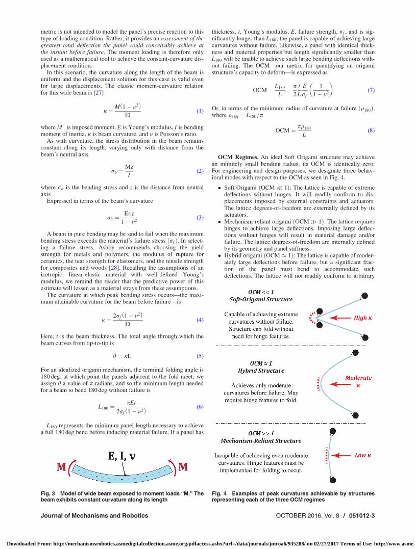
metric is not intended to model the panel’s precise reaction to thistype of loading condition. Rather, it provides an assessment of thegreatest total deflection the panel could conceivably achieve atthe instant before failure. The moment loading is therefore onlyused as a mathematical tool to achieve the constant-curvature dis-placement condition.
In this scenario, the curvature along the length of the beam isuniform and the displacement solution for this case is valid evenfor large displacements. The classic moment-curvature relationfor this wide beam is [27]
j ¼ M 1� �2ð ÞEI
(1)
where M is imposed moment, E is Young’s modulus, I is bendingmoment of inertia, j is beam curvature, and � is Poisson’s ratio.
As with curvature, the stress distribution in the beam remainsconstant along its length, varying only with distance from thebeam’s neutral axis
rb ¼Mz
I(2)
where rb is the bending stress and z is the distance from neutralaxis
Expressed in terms of the beam’s curvature
rb ¼Ejz
1� �2(3)
A beam in pure bending may be said to fail when the maximumbending stress exceeds the material’s failure stress ðrf Þ. In select-ing a failure stress, Ashby recommends choosing the yieldstrength for metals and polymers, the modulus of rupture forceramics, the tear strength for elastomers, and the tensile strengthfor composites and woods [28]. Recalling the assumptions of anisotropic, linear-elastic material with well-defined Young’smodulus, we remind the reader that the predictive power of thisestimate will lessen as a material strays from these assumptions.
The curvature at which peak bending stress occurs—the maxi-mum attainable curvature for the beam before failure—is
j ¼ 2rf 1� �2ð ÞEt
(4)
Here, t is the beam thickness. The total angle through which thebeam curves from tip-to-tip is
h ¼ jL (5)
For an idealized origami mechanism, the terminal folding angle is180 deg, at which point the panels adjacent to the fold meet; weassign h a value of p radians, and so the minimum length neededfor a beam to bend 180 deg without failure is
L180 ¼pEt
2rf 1� �2ð Þ (6)
L180 represents the minimum panel length necessary to achievea full 180 deg bend before inducing material failure. If a panel has
thickness, t, Young’s modulus, E, failure strength, rf , and is sig-nificantly longer than L180, the panel is capable of achieving largecurvatures without failure. Likewise, a panel with identical thick-ness and material properties but length significantly smaller thanL180 will be unable to achieve such large bending deflections with-out failing. The OCM—our metric for quantifying an origamistructure’s capacity to deform—is expressed as
OCM ¼ L180
L¼ p
2
t
L
E
rf
1
1� �2
� �(7)
Or, in terms of the minimum radius of curvature at failure ðq180Þ,where q180 ¼ L180=p
OCM ¼ pq180
L(8)
OCM Regimes. An ideal Soft Origami structure may achievean infinitely small bending radius; its OCM is identically zero.For engineering and design purposes, we designate three behav-ioral modes with respect to the OCM as seen in Fig. 4.
� Soft Origami ðOCM� 1Þ: The lattice is capable of extremedeflections without hinges. It will readily conform to dis-placements imposed by external constraints and actuators.The lattice degrees-of-freedom are externally defined by itsactuators.
� Mechanism-reliant origami ðOCM� 1Þ: The lattice requireshinges to achieve large deflections. Imposing large deflec-tions without hinges will result in material damage and/orfailure. The lattice degrees-of-freedom are internally definedby its geometry and panel stiffness.
� Hybrid origami ðOCM � 1Þ: The lattice is capable of moder-ately large deflections before failure, but a significant frac-tion of the panel must bend to accommodate suchdeflections. The lattice will not readily conform to arbitrary
Fig. 3 Model of wide beam exposed to moment loads “M.” Thebeam exhibits constant curvature along its length
Fig. 4 Examples of peak curvatures achievable by structuresrepresenting each of the three OCM regimes
Journal of Mechanisms and Robotics OCTOBER 2016, Vol. 8 / 051012-3
Downloaded From: http://mechanismsrobotics.asmedigitalcollection.asme.org/pdfaccess.ashx?url=/data/journals/jmroa6/935288/ on 02/27/2017 Terms of Use: http://www.asme.org/about-asme/terms-of-use
geometries. The lattice degrees-of-freedom depend on bothits external actuators and its own geometry/stiffness (it is notexclusively internally or exclusively externally defined).
When evaluating a system using this metric, it is important toremember that the OCM value is not a measure of the structure’sresistance to deflection under load; it is not a stiffness estimate.Rather, it is a measure of the structure’s capacity to achieve largedeflections without failing.
OCM Examples. In Table 1, we give two OCM values to pro-vide an intuitive example of what the OCM value means; plasticwrap and sheet metal serve as familiar examples. Often to thefrustration of the user, plastic wrap used for storing food seemscapable of assuming virtually any shape and it falls well withinthe Soft Origami regime. By comparison, a 1.5-mm thick steelsquare would be classified as a mechanism-reliant structurebecause it must experience significant yielding before even mod-erate deflections would occur.
Design Factors for Tuning an Assembly’s OCM Value. Anengineer interested in tuning the OCM of an origami system maydo so by adjusting the system’s material properties and geometry.The relationship between the OCM and the tunable property isproportional to first order in both cases
OCM / t=L (9)
OCM / E=rf (10)
Origami designs are typically specified with prescribed panelshapes and lengths, so adjustment of the OCM value by geometryis most easily accomplished by changing the thickness of the fold-ing substrate. Panel thickness values are generally dictated by ma-terial processing limitations and design requirements of thesystem, though thickness changes of 1–2 orders of magnitude arefeasible in some cases.
The OCM varies by roughly 3 orders of magnitude for differentengineering materials, with the ratio E=rf ranging from a mini-mum of roughly �10 (plastics and polymers) to a maximum of�10; 000 (some metals and ceramics). Performance may thereforebe changed drastically by simply selecting a different material forfolding.
In the limiting case where both the geometric and materialratios range from their extreme values, the OCM value mayvary by a factor of �100; 000: In practice, where the rangeof valid materials and geometries is more limited, a more feasibleexpectation for adjustment of the OCM value is a factor of�100 – �1000.
Extension to Nonuniform Origami Sheets. A lattice exhibit-ing nonuniformities in thickness, in panel dimensions, or in mate-rial properties may not exhibit a constant OCM across its entirestructure. In this case, the full range of OCM values for the latticemust be considered. Calculating the OCM across all panels allowsone to produce a map of the compliance behavior across the struc-ture, while calculating the OCM for the least- and most-compliantpanels will produce the range of values under which the lattice
will behave. Even if some or many values differ, if all values arecontained within a single compliance regime, the lattice as awhole may be said to behave within that regime (it will be glob-ally soft, hybrid, or mechanism-reliant). If the OCM values spanmultiple regimes, the lattice will exhibit locally soft, hybrid, ormechanism-reliant behavior but global classification for the entirestructure is not possible.
Limitations. The fifth assumption in this model—negligibleanticlastic deformations—assumes the local radius of curvature islarge in comparison with the thickness of the material. In thisanalysis, the radius of curvature/thickness ratio may be written as
q180
t¼ E
2rf(11)
For most engineering materials, the ratio of Young’s modulus (E)to failure stress (rf ) is at least 10:1; for metals and many plasticsand polymers, the ratio is approaches or exceeds 100:1 [6]. In thecase of these materials, the approximation presented will serve asa good estimate of the material’s response to an induced deflec-tion. However, many elastomers exhibit ratios less than 1:1 andthe designer should proceed with caution.
Constraint of Soft Origami Structures
Rayleigh–Ritz Buckling Criterion. Ideal Soft Origami struc-tures cannot support compressive loads and must be constrainedexternally. This is easily demonstrated using the Rayleigh–Ritzbuckling quotient resulting from the principle of virtual work. Fora beam of relatively great width, the net critical compressive loadneeded to induce buckling is [29]
N ¼ EI
1� �2
ðL
0
dw00dw00dx
ðL
0
dw0dw0dx
(12)
where N is critical buckling load, E is Young’s modulus, I is thebending moment of inertia, L is the beam length, and � is Pois-son’s ratio.
In this formulation, w is the characteristic shape function asso-ciated with deflection during buckling. The variables dw0 and dw00
are the first and second variations of the shape function,respectively.
The zero-thickness assumption for an ideal Soft Origami struc-ture produces a zero-valued moment of inertia ðIÞ and therefore azero-valued critical buckling load; the structure will buckle underany imposed compressive load.
Tension to Prevent Buckling and Sagging. As demonstrated,ideal Soft Origami cannot sustain a net compressive load, butinduced tensile forces are tolerable and will work to prevent buck-ling. This result has important practical implications: to avoidbuckling failure in a functional Soft Origami device (which expe-riences loads such as gravity), one must maintain a net tension ineach in-plane direction across all points on all faces. This couldbe accomplished (though perhaps not in the most practical way)by assigning an actuator to each vertex and then maintaining atension force between all adjacent actuator pairs (each pair of ver-tices connected by a single edge on the folding diagram).
Sagging of the panel due to gravity is also counteracted byimposing tension. An upper bound for the tension needed toacceptably counteract sagging can be derived by assuming aworst-case scenario where: (a) the panel is positioned horizontally(gravity acts transversely) and (b) the panel behaves as ideal SoftOrigami (it has zero bending stiffness). Making these assump-tions, a Soft Origami panel behaves as a level-span catenary
Table 1 Example OCM values for two 25 mm3 25 mm panels
Plastic wrap (HDPE) Sheet metal (1018 Steel)
E ðGPaÞ 1 205t ðmmÞ 0.0125 1.5rf ðMPaÞ 20 250L ðmmÞ 25 25� 0.40 0.29OCM 0.047 84
051012-4 / Vol. 8, OCTOBER 2016 Transactions of the ASME
Downloaded From: http://mechanismsrobotics.asmedigitalcollection.asme.org/pdfaccess.ashx?url=/data/journals/jmroa6/935288/ on 02/27/2017 Terms of Use: http://www.asme.org/about-asme/terms-of-use

element, as shown in Fig. 5. We seek an expression for the hori-zontal tension force (relative to the weight of the panel) requiredto reduce sagging below a desired level; this relationship isderived here.
We begin with the two well-known equations governing astandard catenary element
D ¼H cos h
Sw
2H
� �� 1
� �
w(13)
L ¼2Hð Þsin h
Sw
2H
� �
w(14)
where S is the spanned length, D is the sag height, w is the panelweight per unit length, L is panel length, H is horizontal tensionforce, and g is direction of gravity.
We define the horizontal tension force to be a multiple, c, of thetotal panel weight
c ¼ H
Lw(15)
where c is the tension ratio (horizontal tension to total spanweight).
Solving for the suspension length, L, needed to span S with atension ratio c
L ¼ S
2cð Þsin h�11
2c
� � (16)
The nondimensional ratio of sag height to the spanned length,D=S, as a function of tension ratio c, can therefore be expressed as
D
S¼
ffiffiffiffiffiffiffiffiffiffiffiffiffiffiffi1
4c2þ 1
r� 1
2csch�1 2cð Þ(17)
The sagging ratio is highly sensitive to the horizontal tensionratio, as seen on the log–log plot in Fig. 6.
As the tension ratio reaches c ¼ 10 (where the horizontal ten-sion force is ten times the weight of the panel), the sagging ratiois approximately D=S ¼ 0:0125. We therefore recommend a ten-sion ratio of c ¼ 10 or greater in order to reduce sag error below1:25% (sagging is further reduced by panel stiffness and increas-ingly vertical orientation).
Degrees-of-Freedom. For a folding pattern with n vertices, weassign n actuators. As each vertex has three translational degrees-of-freedom in Cartesian space, an ideal Soft Origami structure—with zero-thickness, zero weight, and zero minimum bendingradius—therefore can be idealized to have 3n degrees-of-freedom.This assumes there are no rotational degrees-of-freedom associ-ated with the vertices.
We may use this result to approximate a nonideal structure’sdegrees-of-freedom as also being 3n; this approximation becomesmore accurate with decreasing OCM values, decreasing contactarea at the actuator–lattice interface, and increasing the imposedtensions (this will reduce sagging deflections induced by gravity).
Actuation of Soft Origami Structures
Any actuation mechanism for folding Soft Origami must satisfymany functional requirements. An ideal actuation mechanismmust:
� Constrain and actuate each vertex� Avoid interference between actuators/actuation points� Simultaneously actuate all vertices along precise paths� Achieve large actuation strokes relative to the lattice size� Possess great stiffness relative to that of the folding lattice� Avoid any self-interference� Robustly scale with the number of vertices� Robustly scale with the characteristic panel size
Of these, robust scaling with respect to vertex count is perhapsthe most difficult requirement. This is because, for a square gridof vertices, the total vertex count scales as n2; where n is the ver-tex count on an edge. Folding of very small Soft Origami assem-blies is straightforward, as an independent, dedicated actuator canbe assigned to each vertex. This approach loses feasibility as thesize of the origami lattice increases. For example, the latticedepicted in Fig. 7—measuring just six panels by six panels—
Fig. 5 The level-span catenary suspension representation ofsagging panel. Note that vertical forces (not pictured here) arealso exerted at the endpoints of the span, with total magnitudeequivalent to the weight of the span.
Fig. 6 Sagging ratio as a function of tension ratio
Fig. 7 6 3 6-panel Miura-ori folding diagram. Dotted lines, solidinteral lines, and dots represent valley folds, mountain folds,and vertices, respectively.
Journal of Mechanisms and Robotics OCTOBER 2016, Vol. 8 / 051012-5
Downloaded From: http://mechanismsrobotics.asmedigitalcollection.asme.org/pdfaccess.ashx?url=/data/journals/jmroa6/935288/ on 02/27/2017 Terms of Use: http://www.asme.org/about-asme/terms-of-use
would already require nearly 50 separate actuators. For large sys-tems with dozens, hundreds, or thousands of actuation points,individual actuation is not practical and a new approach is needed.
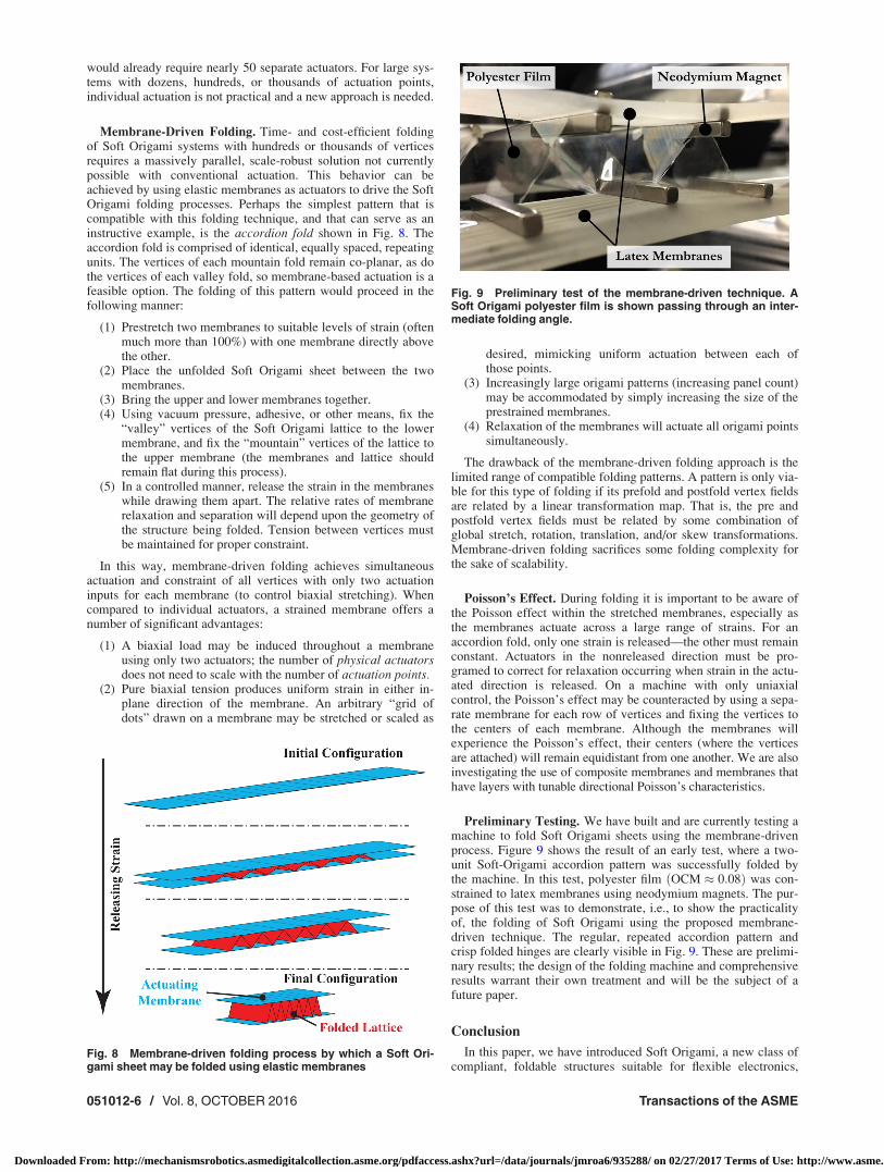
Membrane-Driven Folding. Time- and cost-efficient foldingof Soft Origami systems with hundreds or thousands of verticesrequires a massively parallel, scale-robust solution not currentlypossible with conventional actuation. This behavior can beachieved by using elastic membranes as actuators to drive the SoftOrigami folding processes. Perhaps the simplest pattern that iscompatible with this folding technique, and that can serve as aninstructive example, is the accordion fold shown in Fig. 8. Theaccordion fold is comprised of identical, equally spaced, repeatingunits. The vertices of each mountain fold remain co-planar, as dothe vertices of each valley fold, so membrane-based actuation is afeasible option. The folding of this pattern would proceed in thefollowing manner:
(1) Prestretch two membranes to suitable levels of strain (oftenmuch more than 100%) with one membrane directly abovethe other.
(2) Place the unfolded Soft Origami sheet between the twomembranes.
(3) Bring the upper and lower membranes together.(4) Using vacuum pressure, adhesive, or other means, fix the
“valley” vertices of the Soft Origami lattice to the lowermembrane, and fix the “mountain” vertices of the lattice tothe upper membrane (the membranes and lattice shouldremain flat during this process).
(5) In a controlled manner, release the strain in the membraneswhile drawing them apart. The relative rates of membranerelaxation and separation will depend upon the geometry ofthe structure being folded. Tension between vertices mustbe maintained for proper constraint.
In this way, membrane-driven folding achieves simultaneousactuation and constraint of all vertices with only two actuationinputs for each membrane (to control biaxial stretching). Whencompared to individual actuators, a strained membrane offers anumber of significant advantages:
(1) A biaxial load may be induced throughout a membraneusing only two actuators; the number of physical actuatorsdoes not need to scale with the number of actuation points.
(2) Pure biaxial tension produces uniform strain in either in-plane direction of the membrane. An arbitrary “grid ofdots” drawn on a membrane may be stretched or scaled as
desired, mimicking uniform actuation between each ofthose points.
(3) Increasingly large origami patterns (increasing panel count)may be accommodated by simply increasing the size of theprestrained membranes.
(4) Relaxation of the membranes will actuate all origami pointssimultaneously.
The drawback of the membrane-driven folding approach is thelimited range of compatible folding patterns. A pattern is only via-ble for this type of folding if its prefold and postfold vertex fieldsare related by a linear transformation map. That is, the pre andpostfold vertex fields must be related by some combination ofglobal stretch, rotation, translation, and/or skew transformations.Membrane-driven folding sacrifices some folding complexity forthe sake of scalability.
Poisson’s Effect. During folding it is important to be aware ofthe Poisson effect within the stretched membranes, especially asthe membranes actuate across a large range of strains. For anaccordion fold, only one strain is released—the other must remainconstant. Actuators in the nonreleased direction must be pro-gramed to correct for relaxation occurring when strain in the actu-ated direction is released. On a machine with only uniaxialcontrol, the Poisson’s effect may be counteracted by using a sepa-rate membrane for each row of vertices and fixing the vertices tothe centers of each membrane. Although the membranes willexperience the Poisson’s effect, their centers (where the verticesare attached) will remain equidistant from one another. We are alsoinvestigating the use of composite membranes and membranes thathave layers with tunable directional Poisson’s characteristics.
Preliminary Testing. We have built and are currently testing amachine to fold Soft Origami sheets using the membrane-drivenprocess. Figure 9 shows the result of an early test, where a two-unit Soft-Origami accordion pattern was successfully folded bythe machine. In this test, polyester film ðOCM � 0:08Þ was con-strained to latex membranes using neodymium magnets. The pur-pose of this test was to demonstrate, i.e., to show the practicalityof, the folding of Soft Origami using the proposed membrane-driven technique. The regular, repeated accordion pattern andcrisp folded hinges are clearly visible in Fig. 9. These are prelimi-nary results; the design of the folding machine and comprehensiveresults warrant their own treatment and will be the subject of afuture paper.
Conclusion
In this paper, we have introduced Soft Origami, a new class ofcompliant, foldable structures suitable for flexible electronics,
Fig. 8 Membrane-driven folding process by which a Soft Ori-gami sheet may be folded using elastic membranes
Fig. 9 Preliminary test of the membrane-driven technique. ASoft Origami polyester film is shown passing through an inter-mediate folding angle.
051012-6 / Vol. 8, OCTOBER 2016 Transactions of the ASME
Downloaded From: http://mechanismsrobotics.asmedigitalcollection.asme.org/pdfaccess.ashx?url=/data/journals/jmroa6/935288/ on 02/27/2017 Terms of Use: http://www.asme.org/about-asme/terms-of-use
folding tissue scaffolds, and other applications where conven-tional rigid and mechanistic origami structures may not be suita-ble. We developed the OCM, a means by which candidatematerials and geometries are evaluated for fitness within the SoftOrigami regime. We demonstrate that despite their extreme com-pliance, Soft Origami structures can be well-constrained if held atall vertices and maintained in tension. Finally, we have introduceda scale-robust process capable of both constraining and foldingSoft Origami structures, wherein just two stretching membranesare needed to drive the folding process even if the origami struc-ture is very large.
Acknowledgment
This research was supported by the National Science Founda-tion and the Air Force Office of Scientific Research through theEFRI-ODISSEI program under Grant No. 1332249.
References[1] Siegel, A. C., Phillips, S. T., Dickey, M. D., Lu, N., Suo, Z., and Whitesides, G.
M., 2010, “Foldable Printed Circuit Boards on Paper Substrates,” Adv. Funct.Mater., 20(1), pp. 28–35.
[2] Chen, A. A., Thomas, D. K., Ong, L. L., Schwartz, R. E., Golub, T. R., andBhatia, S. N., 2011, “Humanized Mice With Ectopic Artificial Liver Tissues,”Proc. Natl. Acad. Sci. U.S.A., 108(29), pp. 11842–11847.
[3] Levenberg, S., Rouwkema, J., Macdonald, M., Garfein, E. S., Kohane, D. S.,Darland, D. C., Marini, R., van Blitterswijk, C. A., Mulligan, R. C., D’Amore,P. A., and Langer, R., 2005, “Engineering Vascularized Skeletal MuscleTissue,” Nat. Biotechnol., 23(7), pp. 879–884.
[4] Stevens, K. R., Kreutziger, K. L., Dupras, S. K., Korte, F. S., Regnier, M.,Muskheli, V., Nourse, M. B., Bendixen, K., Reinecke, H., and Murry, C. E.,2009, “Physiological Function and Transplantation of Scaffold-Free and Vascu-larized Human Cardiac Muscle Tissue,” Proc. Natl. Acad. Sci. U.S.A., 106(39),pp. 16568–16573.
[5] Glicklis, R., Merchuk, J. C., and Cohen, S., 2004, “Modeling Mass Transfer inHepatocyte Spheroids Via Cell Viability, Spheroid Size, and HepatocellularFunctions,” Biotechnol. Bioeng., 86(6), pp. 672–680.
[6] Wood, F. M., Stoner, M. L., Fowler, B. V., and Fear, M. W., 2007, “The Use ofa Non-Cultured Autologous Cell Suspension and Integra
VR
Dermal RegenerationTemplate to Repair Full-Thickness Skin Wounds in a Porcine Model: A One-Step Process,” Burns, 33(6), pp. 693–700.
[7] Atala, A., Bauer, S. B., Soker, S., Yoo, J. J., and Retik, A. B., 2006, “Tissue-Engineered Autologous Bladders for Patients Needing Cystoplasty,” Lancet,367(9518), pp. 1241–1246.
[8] Macchiarini, P., Jungebluth, P., Go, T., Asnaghi, M. A., Rees, L. E., Cogan, T.A., Dodson, A., Martorell, J., Bellini, S., Parnigotto, P. P., Dickinson, S. C.,Hollander, A. P., Mantero, S., Conconi, M. T., and Birchall, M. A., 2008,“Clinical Transplantation of a Tissue-Engineered Airway,” Lancet, 372(9655),pp. 2023–2030.
[9] Shin’oka, T., Imai, Y., and Ikada, Y., 2001, “Transplantation of a Tissue-Engineered Pulmonary Artery,” N. Engl. J. Med., 344(7), pp. 532–533.
[10] Jakab, K., Norotte, C., Marga, F., Murphy, K., Vunjak-Novakovic, G., and For-gacs, G., 2010, “Tissue Engineering by Self-Assembly and Bio-Printing of Liv-ing Cells,” Biofabrication, 2(2), p. 022001.
[11] Miller, J. S., Stevens, K. R., Yang, M. T., Baker, B. M., Nguyen, D.-H. T.,Cohen, D. M., Toro, E., Chen, A. A., Galie, P. A., Yu, X., Chaturvedi, R., Bha-tia, S. N., and Chen, C. S., 2012, “Rapid Casting of Patterned Vascular Net-works for Perfusable Engineered Three-Dimensional Tissues,” Nat. Mater.,11(9), pp. 768–774.
[12] Tachi, T., 2009, “Generalization of Rigid Foldable Quadrilateral MeshOrigami,” International Association for Shell and Spatial Structures (IASS)Symposium, Valencia, Spain, Sept. 28–Oct. 2, pp. 2287–2294.
[13] Belcastro, S.-M., and Hull, T. C., 2002, “A Mathematical Model for Non-FlatOrigami,” Origami3: 3rd International Meeting of Origami Mathematics, Sci-ence, and Education, Monterey, CA, Mar. 9–11, A. K. Peters, Natick, MA, pp.39–51.
[14] Tachi, T., 2009, “Simulation of Rigid Origami,” Origami, 4, pp. 175–187.[15] Bowen, L. A., Baxter, W. L., Magleby, S. P., and Howell, L. L., 2014, “A Posi-
tion Analysis of Coupled Spherical Mechanisms Found in Action Origami,”Mech. Mach. Theory, 77, pp. 13–24.
[16] Noy, B., George, M. S., Alla, B., Nana, Y. A., and David, H. G., 2011, “Hands-Free Microscale Origami,” Origami 5, CRC Press, Boca Raton, FL, pp.371–384.
[17] Kuribayashi-Shigetomi, K., Onoe, H., and Takeuchi, S., 2012, “Cell Origami:Self-Folding of Three-Dimensional Cell-Laden Microstructures Driven by CellTraction Force,” PLoS One, 7(12), p. e51085.
[18] Shenoy, V. B., and Gracias, D. H., 2012, “Self-Folding Thin-Film Materi-als: From Nanopolyhedra to Graphene Origami,” MRS Bull., 37(9),pp. 847–854.
[19] Liu, Y., Boyles, J. K., Genzer, J., and Dickey, M. D., 2012, “Self-Folding ofPolymer Sheets Using Local Light Absorption,” Soft Matter, 8(6), pp.1764–1769.
[20] Hawkes, E., An, B., Benbernou, N. M., Tanaka, H., Kim, S., Demaine, E. D.,Rus, D., and Wood, R. J., 2010, “Programmable Matter by Folding,” Proc. Natl.Acad. Sci. U.S.A., 107(28), pp. 12441–12445.
[21] Felton, S. M., Tolley, M. T., Shin, B. H., Onal, C. D., Demaine, E. D., Rus, D.,and Wood, R. J., 2013, “Self-Folding With Shape Memory Composites,” SoftMatter, 9(32), pp. 7688–7694.
[22] Ryu, J., D’Amato, M., Cui, X., Long, K. N., Qi, H. J., and Dunn, M. L., 2012,“Photo-Origami—Bending and Folding Polymers With Light,” Appl. Phys.Lett., 100(16), p. 161908.
[23] Fernandes, R., and Gracias, D. H., 2012, “Self-Folding Polymeric Containersfor Encapsulation and Delivery of Drugs,” Adv. Drug Delivery Rev., 64(14),pp. 1579–1589.
[24] Bassik, N., Stern, G. M., and Gracias, D. H., 2009, “Microassembly Based onHands Free Origami With Bidirectional Curvature,” Appl. Phys. Lett., 95(9),p. 091901.
[25] Randall, C. L., Gultepe, E., and Gracias, D. H., 2012, “Self-Folding Devicesand Materials for Biomedical Applications,” Trends Biotechnol., 30(3),pp. 138–146.
[26] Timoshenko, S. P., and Goodier, J., 1951, Theory of Elasticity, McGraw-Hill,New York.
[27] Young, W. C., Budynas, R. G., and Sadegh, A. M., 2012, Formulas for Stressand Strain, 8th ed., McGraw-Hill, New York.
[28] Ashby, M. F., 2005, Materials Selection in Mechanical Design, Butterworth-Heinemann, Oxford, UK.
[29] Ragab, A.-R. A., and Bayoumi, S. E. A., 1998, Engineering Solid Mechanics:Fundamentals and Applications, CRC Press, Boca Raton, FL.
Journal of Mechanisms and Robotics OCTOBER 2016, Vol. 8 / 051012-7
Downloaded From: http://mechanismsrobotics.asmedigitalcollection.asme.org/pdfaccess.ashx?url=/data/journals/jmroa6/935288/ on 02/27/2017 Terms of Use: http://www.asme.org/about-asme/terms-of-use