softswitchboard - bticino€¦ · 2.2 “outgoing calls” area 5 2.3 “cameras” area 6 ... open...
TRANSCRIPT

SoftSwitchboard
User Manual
09/15-01 PC

2

3
SoftSwitchboard
Use
r Man
ual
Index1. Introduction 4
2. Description of the interface 42.1 “Incoming calls” area 5
2.2 “Outgoing calls” area 5
2.3 “Cameras” area 6
2.4 “Alarms” area 6
3. Contatti 7
4. Messages 7
5. TiDirectCall 8
5. Alarms 10
6. Examples of use 116.1 Managing a call from the EP 11
6.2 Managing a call from the IP 14
6.3 Sending messages 15
6.4 Receiving messages 17
6.5 Managing alarms 18
7. FAQ 23
4
1. Introduction
2. Description of the interface
In addition to the standard functions (opening locks and video control), when correctly configured using the SwitchBoardConfig program, the SoftSwitchboard program can also be used to receive and forward audio/video calls, manage alarms from individual Handsets, as well as for sending and receiving text messages from handsets and other switchboards.Note: in this manual, the term
Switchboard is used when refer-ring to the SoftSwitchboard sof-tware.
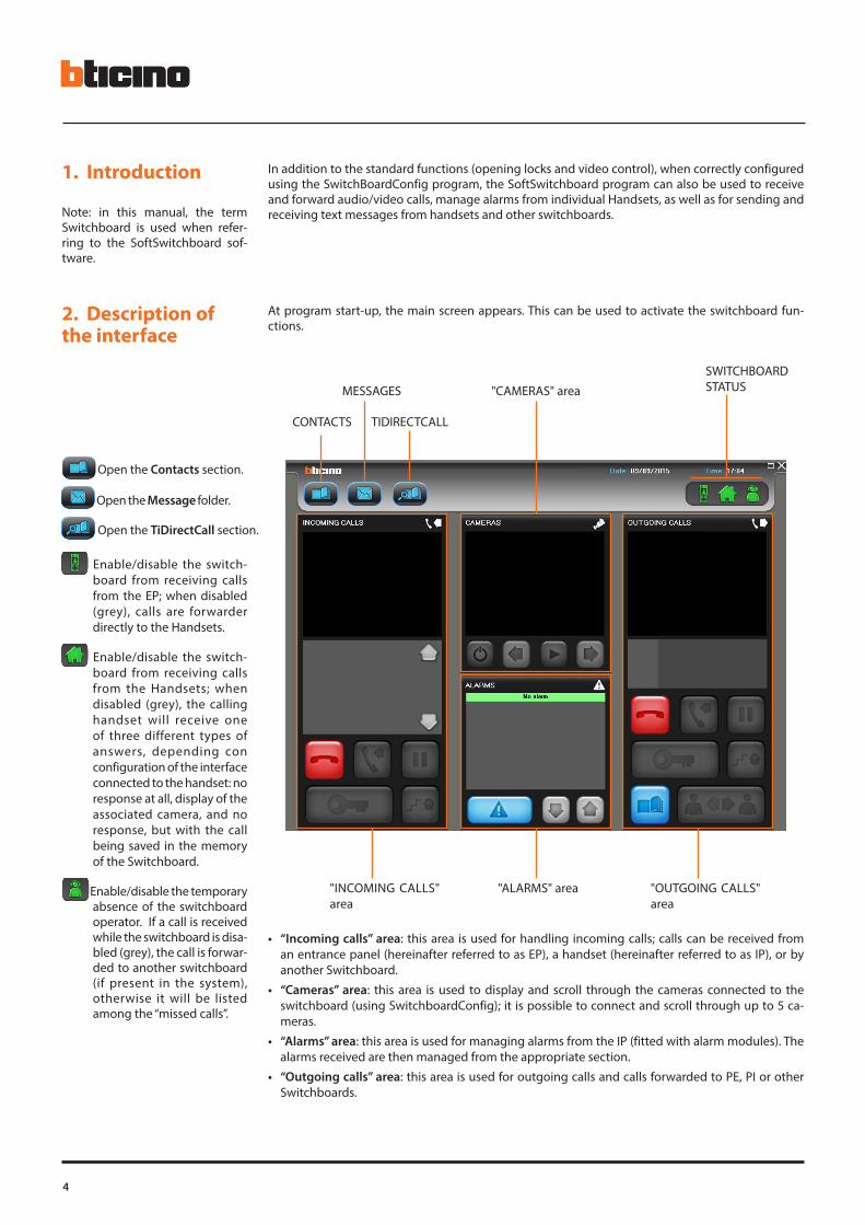
At program start-up, the main screen appears. This can be used to activate the switchboard fun-ctions.
• “Incoming calls” area: this area is used for handling incoming calls; calls can be received from an entrance panel (hereinafter referred to as EP), a handset (hereinafter referred to as IP), or by another Switchboard.
• “Cameras” area: this area is used to display and scroll through the cameras connected to the switchboard (using SwitchboardConfig); it is possible to connect and scroll through up to 5 ca-meras.
• “Alarms” area: this area is used for managing alarms from the IP (fitted with alarm modules). The alarms received are then managed from the appropriate section.
• “Outgoing calls” area: this area is used for outgoing calls and calls forwarded to PE, PI or other Switchboards.
"INCOMING CALLS" area
"ALARMS" area "OUTGOING CALLS" area
"CAMERAS" areaMESSAGES
SWITCHBOARD STATUS
Open the Contacts section.
Open the TiDirectCall section.
Open the Message folder.
Enable/disable the switch-board from receiving calls from the EP; when disabled (grey), calls are forwarder directly to the Handsets.
Enable/disable the switch-board from receiving calls from the Handsets; when disabled (grey), the calling handset will receive one of three different types of answers, depending con configuration of the interface connected to the handset: no response at all, display of the associated camera, and no response, but with the call being saved in the memory of the Switchboard.
CONTACTS TIDIRECTCALL
Enable/disable the temporary absence of the switchboard operator. If a call is received while the switchboard is disa-bled (grey), the call is forwar-ded to another switchboard (if present in the system), otherwise it will be listed among the “missed calls”.

SoftSwitchboard
Use
r Man
ual
5
2.1 “Incoming calls” area
Using the keys described below, this area can be used to manage calls from EP, IP or Switchboards. The image sent from the camera connected to the EP or the Switchboard can also be displayed.
2.2 “Outgoing calls” area
Using the keys described below, this area can be used to manage outgoing calls to EP, IP or the Switch-board. The image sent from the camera connected to the EP or from another Switchboard can also be displayed.
Camera area
Switch the staircase lights on
Open the address book
Establish communication between the IP and EP
Put the call on hold
Call IPs, EPs and Switchboards
End the call
Call information area
Camera area
List of missed calls, if green, the call is active
End the call or delete a missed call from the list
Answer the call or to call the missed caller back
Put the call on hold
Switch the staircase lights on
Scroll through calls
When there are several suit-ably configured door locks at rest, they will all activate simultaneously.
During the communication/call only opens the door lock of the caller or con-nected EP.If there is no connection instead it opens the door lock(s) configured at rest
During the communication/call only opens the door lock of the caller or con-nected EP.If there is no connection instead it opens the door lock(s) configured at rest

6
2.3 “Cameras” area
Using the keys described below, this area can be used to enable/disable the display and scroll through all connected cameras.
2.4 “Alarms” area
Using the keys described below, this area can be used to display current alarms received from the IPs. Click on the Alarms key to access the corresponding section, and manage the alarm received.
Cameras area
List of active alarms
Open the Alarms section
Scroll through the alarms
Activates/deactivates the camera dis-play. After 30”, without doing anything else, the camera switches off and when it is activated with the same pushbut-ton it displays the camera following that previously displayed
Cycles manually going to the previous camera
Cycles manually going to the next cam-era
Automatically cycles the cameras

SoftSwitchboard
Use
r Man
ual
7
4. Messages This section can be used to send and/or receive messages to/from other Switchboards or IPs. For mana-ging messages, the main message management functions typical of e-mail clients have been included.
The following screen appears:
> Click Messages (when new messages are present, the icon is green. Once pressed, the icon returns to normal status) The following screen appears:
Note: the message function can only be used on enabled IP.
Display the saved EP
Display the saved Switchboards
Contacts information
Scroll through contacts
Confirm the selection of the contact to call
New message
Message management
Read messages
Message filter
Deleted messages
Permanently delete the messages from the bin
Scroll through messages
Outgoing messages
Sent messages
Received messages
Deleted messages
3. Contacts This section is used to display and select contacts previously created using TiContacts.To access the contacts section:
> Click Contacts
Display the saved apartments

8
5. TiDirectCall This section can be used to directly call entrance panels, switchboards, and apartments previously saved using TiContacts.The TiDirectCall section can be displayed in two ways, based on the configuration performed using TiContacts
> Click TiDirectCall
The following window appears:
Apartments
Entrance panels
Switchboards
1 1 > Select the desired block
2
2 > Select the desired floor
3 3 > Select the desired apartment
Clear the fields to perform a new search
Call the selected apartment

SoftSwitchboard
Use
r Man
ual
9
> Click TiDirectCall
Use this key to call the apartment, switchboard or entrance panel, after entering its complete address (in numeric format only):
1
1 > Call the selected apartment
Example:0001 = block 01 = floor 02 = apartment
Open the door lock
Activate the camera associate to the entrance panel
Call the selected apart-ment
Cancel
Call another system switchboard

10
5. Alarms In this section the technical alarms from one or more MyHOME apartments configured with the video door entry system or from the Alarm Modules (349416/17/19) associated to the IU can be managed. The alarms received are processed by the Switchboard and closed after the necessary operations have been performed. Alarm related events and their characteristics can also be displayed in the Events History section. To access the alarm section:
> Click the Alarms key
The following screen appears:
Scroll through the alarms
Alarmsmanagement
Take charge of the alarms
Active alarms
This screen displays active alarms.
Alarm to terminate This screen displays the alarms for which charge has already been taken, and which need to be terminated.
Alarm history
This screen displays the alarm history.
Events history This screen can be used to reconstruct the history of events connected with an alarm.
To create groups, drag the heading of the column in the grouping area.

SoftSwitchboard
Use
r Man
ual
11
6. Examples of use 6.1 Managing a call from the EP
This example shows how the Switchboard can handle a call from the EP.
The area "Incoming calls" displays the im-age being recorded by the camera of the EP displayed in the "Call information" area.
> The switchboard answers the call
The Switchboard receives a call from the EP.
> After listening, the EP puts the call on hold
The image of the connected camera disap-pears.
12
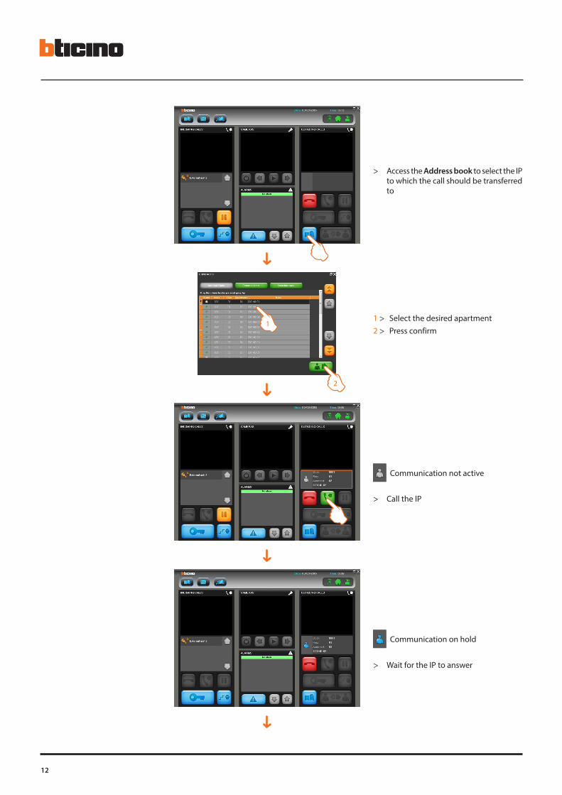
1 > Select the desired apartment 2 > Press confirm
Communication on hold
Communication not active
> Access the Address book to select the IP to which the call should be transferred to
> Call the IP
> Wait for the IP to answer
1
2

SoftSwitchboard
Use
r Man
ual
13
The Switchboard is now free to receive other calls from EPs or IPs.
The IP displays the image from the EP camera.
> Put the call on hold to transfer it
Communication on hold
Communication active
> Establish communication between the IP and the EP

14
6.2 Managing a call from the IP
This example shows how the Switchboard handles a call from IPs.
The IP initiates communication.
The Switchboard receives a call from the IP.
> The switchboard answers the call
Communication on hold
The Switchboard stays on hold, beeping repeatedly until the IP establishes com-munication.
> The IP calls the Switchboard

SoftSwitchboard
Use
r Man
ual
15
6.3 Sending messages
This example shows how to send a text message from the Switchboard.
The IP displays the image from the WebCam (if present and already configured in Switch-BoardConf) connected to the Switchboard.
Communication active
> Enter the Message section
> Click new message
> Enter the Address Book

16
The switchboard can send text messages up to a maxi-mum of 150 characters: we advise however limiting the text length because the IP can only display the first 52 characters of the message.The messages between switchboards will instead be displayed in full.
1
2
1 > Select the address the message is to be sent to (multiple selection is also possible)
2 > Press confirm
1
2
1 > Write a text message of up to 150 characters 2 > Send the message
The progress of the Outgoing message forwarding procedure can be displayed in the outgoing mes-sages screen (in percentage).
The sent Messages screen can be used to display the list of successfully sent messages (green icon). After 24 hours, any messages that the Switchboard is unable to send, will be displayed with an error notification (red icon).
> Double click to display the unsent message
SoftSwitchboard
Use
r Man
ual
17
6.4 Receiving messages
This example shows how to manage received messages.
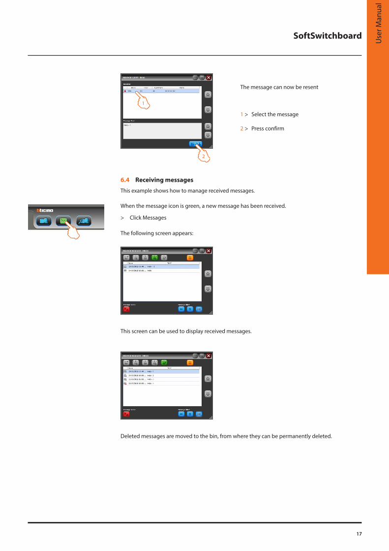
> Click Messages
The following screen appears:
When the message icon is green, a new message has been received.
This screen can be used to display received messages.
Deleted messages are moved to the bin, from where they can be permanently deleted.
1
2
1 > Select the message
2 > Press confirm
The message can now be resent
18
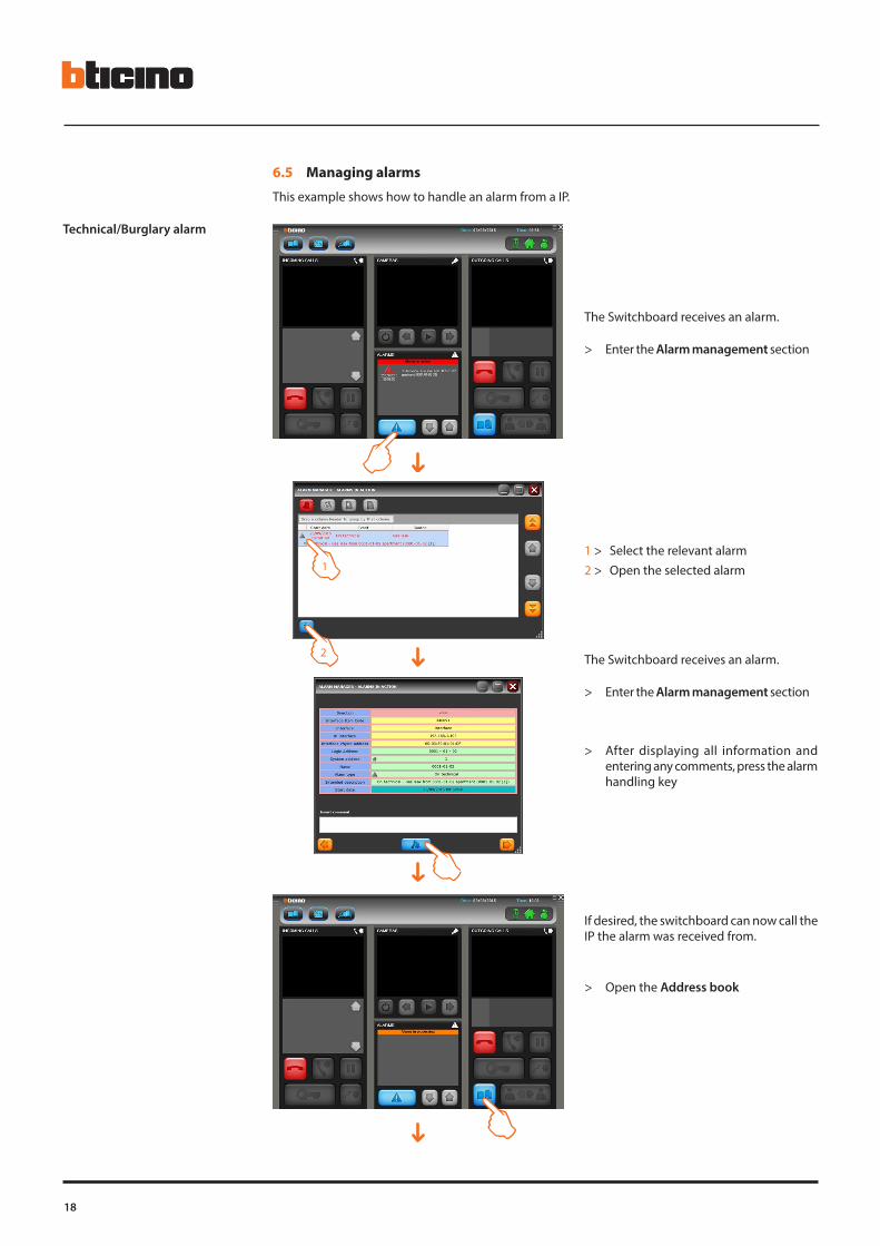
6.5 Managing alarms
This example shows how to handle an alarm from a IP.
Technical/Burglary alarm
The Switchboard receives an alarm.
> Enter the Alarm management section
1 > Select the relevant alarm2 > Open the selected alarm
> After displaying all information and entering any comments, press the alarm handling key
> Open the Address book
The Switchboard receives an alarm.
> Enter the Alarm management section
If desired, the switchboard can now call the IP the alarm was received from.
1
2

SoftSwitchboard
Use
r Man
ual
19
1 > Select the apartment the alarm has been sent from
2 > Press confirm
> Call the IP
> The IP answers
> Enter the Alarm management section again
1
2

20
1 > Select the alarm to terminate 2 > Open the selected alarm 1
2
> After displaying all information and entering any comments, terminate the alarm pressing the relevant key.
Alarm start
Taking charge
Alarm termination
Alarm end
When the alarm is selected in the Events History, all the events connected with the alarm are displayed. This enables recreating the history of the alarm.

SoftSwitchboard
Use
r Man
ual
21
Panic Alarm In case of panic alarm, the Switchboard directly enters into communication with the IP the alarm has been sent from, even if IP has not been saved in the address book.
The Switchboard receives an alarm.
> Enter the Alarm Management session
1 > Select the relevant alarm
2 > Open the selected alarm
> After displaying the information and entering any comments, press the appropriate key for taking charge the alarm. The Switchboard establishes communication with the IP (the call is automatically sent to the IP: only at this time the system accepts that charge of the panic alarm has been taken)
> The IP answers
1
2

22
> Enter the Alarm Management section again
1 > Select the alarm to terminate2 > Open the selected alarm
> After displaying all information and entering any comments, terminate the alarm pressing the relevant key
1
2
When the alarm is selected in the Events History, all the events connected with the alarm are displayed. This enables recreat-ing the history of the alarm.
Alarm start
Taking charge
Alarm termination

SoftSwitchboard
Use
r Man
ual
23
7. FAQ FAQ - MESSAGES1. Why is the message not sent to one or more recipients?
a) The recipient/s is/are not on line; check that the Switchboard or the PI are working correctly.b) The addressee (IU) is not enabled to receive messages: verify that the IU is an Axolute Video
Station (349310), an Axolute Video Display (349311), both with Firmware version 2.0 or higher, or a Classe300.
c) The Switchboard sending the message is not set as reference switchboard on the 346890/91 interface to which the recipient IP is connected; check the interface configuration.
2. Why is the message forwarding procedure not completed, and the message remains in the “Outgoing messages” folder? The Switchboard is unable to send the message to all receivers (see previous question).The switchboard will continue to try and send the message for the next 24 hours: if after 24 hours the switchboard is still unable to complete the message forwarding procedure, the message will be moved to the “Sent messages” folder, with an error notification (red figure); it will now be pos-sible to display in details which receivers have correctly received the message, and only resend the message to the receivers for which the previous message forwarding procedure failed.
3. Why is the address of a recipient not listed in the TiMessage address book?The Switchboard or the IP the user wants to send the message to, have not been entered in the Switchboard address book; Use TiContacts from SwitchboardConfig, to check that the message recipient has been entered correctly in the address book of the active project on the Switchbo-ard.
4. The user only wants to delete some of the messages displayed. Is it necessary to delete them one by one?No, it is possible to select several messages to be deleted at the same time. Click the messages to delete with the mouse, while at the same time pressing and holding down the CTRL key.
FAQ - ALARMS1. Why is the alarm not reaching the Switchboard?
The Switchboard the user expects to receive the alarm notification on, has not been set as refe-rence Switchboard by the 346890/91 interface; check the interface configuration.
2. Why are the details of the IP sending the alarm not included in the alarm details?a) The recipient/s is/are not in line; check that the Switchboard or the PI are working correctly.b) The configuration of the alarm notification module is wrong (349416/17); check configuration
(3 configurators: mode, T1 and T2).c) The IP sending the alarm has not been entered in the Switchboard address book; Use TiCon-
tacts from SwitchboardConfig to check that the IP has been correctly entered in the address book of the active project on the Switchboard. For panic alarm, the alarm will however be taken in charge by forwarding a call to the IP, which will be displayed on the Switchboard as “Unknown” IP.
3. Why are the alarm details not including the details of interface 346890/91 (INT2FIP), to which the IP sending the alarm is connected?The configuration of the alarm notification module is wrong (349416/17); check configuration (3 configurators: mode, T1 and T2).
4. Why is no charge taken of the panic alarm when the appropriate key is pressed (the automatic call is not sent to the IP)?The configuration of the alarm notification module is wrong (349416/17); check configuration (3 configurators: mode, T1 and T2).

BTicino SpAViale Borri, 23121100 Varese - Italywww.bticino.com
BTicino SpA reserves at any time the right to modify the contents of this booklet and to communicate, in any form and modality, the changes brought to the same.