software components framework - rutgers ecemarsic/books/ui/manifold.doc · web viewthe word...
TRANSCRIPT

The ManifoldUser Interface
Framework
Ivan Marsic, CAIP Center, Rutgers University (August 2005)

Table of Contents
1 INTRODUCTION........................................................................................................................11.1 Model-View-Controller Design Pattern.........................................................................11.2 Direct Manipulation........................................................................................................31.3 Conversation Metaphor and Event Frames....................................................................5
2 BASIC USER INTERFACE DESIGN: CORE FRAMEWORK.......................................................72.1 Model Visualization.......................................................................................................7
2.1.1 Structured Graphics Design..............................................................................................72.1.2 Glyph State Caching.......................................................................................................102.1.3 Shadow Glyphs...............................................................................................................102.1.4 The Dynamics of Visualization......................................................................................12
2.2 Parsing the Input Event Sequences...............................................................................132.2.1 Manipulation...................................................................................................................132.2.2 Gestures..........................................................................................................................15
3 ELABORATION OF THE BASIC DESIGN.................................................................................163.1 Interaction with GUI Toolkit and Input Devices..........................................................16
3.1.1 Viewers...........................................................................................................................163.1.2 Controlling the Frame Rate.............................................................................................173.1.3 Presentation Models........................................................................................................18
3.2 Interaction with Application Domain...........................................................................193.2.1 Vocabulary of Slot Verbs...............................................................................................20
3.3 Class Dependencies......................................................................................................21
4 GEOMETRY AND TRANSFORMATIONS..................................................................................234.1 Global, Screen, and Local Coordinate Systems...........................................................234.2 Affine Transformations................................................................................................24
4.2.1 Line Glyph: Zero- and Negative Scaling........................................................................274.3 Traversals.....................................................................................................................28
4.3.1 Draw Traversal...............................................................................................................284.3.2 Pick Traversal.................................................................................................................29
4.4 Manipulation.................................................................................................................314.4.1 Messaging.......................................................................................................................314.4.2 Selection..........................................................................................................................324.4.3 Animation and Simulation..............................................................................................32
5 CONTROLS, DIALOGS, AND LAYOUT....................................................................................345.1 Controls........................................................................................................................345.2 Dialogs and Property Editors........................................................................................345.3 Layout...........................................................................................................................35
6 EXTENSIBILITY AND REUSABILITY......................................................................................396.1 Tools, Manipulators and Controller.............................................................................406.2 Glyphs and Viewers.....................................................................................................40
ii

6.3 Input Device Listeners..................................................................................................416.3.1 Speech.............................................................................................................................416.3.2 Cyber Gloves and Pointing Devices...............................................................................41
7 COMPLEXITY AND PERFORMANCE......................................................................................427.1 Design Complexity.......................................................................................................427.2 Performance..................................................................................................................44
8 DISCUSSION AND CONCLUSIONS...........................................................................................458.1 Bibliography.................................................................................................................45
REFERENCES..................................................................................................................................47
iii

Chapter 1Introduction
An interface provides means to interact with something. For example, your remote control is an interface to your home entertainment system. So is your dashboard to your car. In software developer’s speak, user interface (UI) allows users to interact with the “content” stored in the computer memory (locally or across the network). We assume that the “content” is not an amorphous mass, but rather a structured collection of “elements.” As for any other task, different activities require different “tools.” The user also needs to “see” the stored content, so the “elements” should be visualized using graphical figures. Also, some feedback is required about the effect of the user’s actions on the elements of the content. Real-time feedback between hand motion and vision is very helpful; it visualizes the effects immediately as the user operates on the content, so the user can quickly compare-and-correct his or her actions.
I consider mainly graphical user interfaces, although some attention will be paid to other interface types, such as auditory. Using the user interface, the user can:
Modify the properties of model elements
Select the viewpoint and navigate the “model world”—select which part of the model is visualized (if not all of it fits in the view), which can be done as continuous navigation through the “model space”
The UI developer’s primary concerns are: what can be standardized for reuse, and the layout management.
There are different types of human-computer interaction. The one we focus on here is conversational interaction, but where the conversation is accomplished by manual gestures more than with spoken language. We see user interface playing the role of back-and-forth interpreter between the languages of human and the languages of computer. The analogy with language understanding is exploited extensively and used as inspiration throughout.
UI is usually molded about its particular application domain so that a great deal of work would be required to remold such a UI to a different application. This is particularly true for interfaces based on hand operation of input devices. The design presented here, called Manifold, is an attempt to solve the above problems in an application-independent manner, so that the UI can be easily “detached” from one application and “attached” to another one. The first version of Manifold appeared in [38]. This work is also based on [15,63]. This text is intended to accompany the Manifold software release and to be read along with the code. The best documentation is the code itself, and this text is only meant to improve the readability of the code. It is my hope that the interplay of abstract concepts and actual implementation will allow the reader to understand both specific and broader issues of user interface design.
1.1 Model-View-Controller Design PatternFig. 1 illustrates an abstraction of the user interface. The user generates input device events which are interpreted as actions on the content model. After execution the requested actions, the model sends notifications about the effect of the actions, and the notifications are visualized as feedback
1

to the user. Further clarification of the process is offered by Fig. 2. Notice the optional reading of the new attributes by the View. This is how classical Observer design pattern works [18], i.e., the Observer reads the Subject state upon being notified about the state changes. Conversely, in the Java event delegation pattern [29], the event source sends to the listener the event containing the new state information along with the notification.
The feedback loop does not need to take the entire round-trip through the domain model, to provide visual feedback to the user. The system may instead simulate what would happen should the actions take place, but not execute those actions on the model. Such techniques, e.g., rubber-banding or ghost figures, usually caricature the real model’s operation. The process from Fig. 1 is then shunted, as in this simplified diagram:
input device events => interpretation of events => visual feedback how the content would be altered.
The benefits of the Model-View-Controller (MVC) design pattern were first discussed in [34] and the reader should also check [18,36].
1.2 Direct Manipulation and Direct NavigationDirect manipulation is a form of interaction where the user is presented with the data objects on the display and then manipulates those objects using interactive devices and receives rapid feedback. The word “manipulation” is used as in “to move, arrange, operate, or control … in a skillful manner” (American Heritage Dictionary, Fourth Edition). Direct manipulation provides an illusion of directly interacting with the object with instantaneous feedback in the data visualization. Ben Shneiderman is credited for coining the phrase “direct manipulation” [64,65], see also [28]. He highlights the following characteristics of direct manipulation interfaces:
Visibility of the objects of interest
Incremental action at the interface with rapid feedback on all actions
Reversibility of all actions, so that users are encouraged to explore without severe penalties
2
Fig. 1. This user interface abstraction also illustrates the Model-View-Controller design pattern.

Syntactic correctness of all actions, so that every user action is a legal operation
Replacement of complex command languages with actions to manipulate directly the visible objects (and, hence, the name direct manipulation)
Rapid feedback is critical since it gives the illusion that the user is actually working in the virtual world displayed on the screen. It raises otherwise-obscured awareness of the interaction process. In addition, it quickly provides evaluative information for every executed user action.
Direct manipulation is along the lines of the broader framework of the desktop metaphor, which assumes that we save training time by taking advantage of the time that users have already invested in learning to operate the traditional office with its paper documents and filing cabinets [66].
An example of direct manipulation is illustrated in Fig. 3, where the user moves a file to a folder. In a DOS or UNIX shell, this operation would be executed by typing in commands. For example, in a UNIX shell, it would be:
% mv file child\ folderNote that feedback about the success of the operation is minimal.
Direct manipulation consists of the following steps that run iteratively, for the duration of interaction (see Fig. 4):
1. User points and operates the input device, which results in a low-level event
2. System converts the low-level event to a data processing command
3. System delivers the command to the application-logic module, which executes the command
4. The application-logic module notifies the data visualization module about the data modifications inflicted by the command
5. The visualization module visualizes the updated data
An interaction cycle is defined as a unit block of user interaction with the system. An example of “interaction cycle” is: (1) the user depresses a mouse button; (2) drags the mouse across the workspace; and, (3) releases the mouse button. A cycle can comprise several press-drag-release sequences, for example when creating a polygonal line.
3
Fig. 2. UML sequence diagram abstracting the MVC functioning.

The pointing device may be directly “touching” the visualization of the manipulated object, such as with a stylus pen, or it may do it indirectly, via a cursor shown on the visualization display, as is the case with the mouse.
Note also that the “visualization module” is one example of providing instantaneous feedback to the user. Other examples include tactile or audio feedback, so a more accurate name for this module would be “perceptualization module.”
Direct manipulation paradigm blurs the boundary between the input and the output modules of a software product. The data visualization is used to formulate subsequent input events, so both deal with the same software component. This aggregation of input and output is reflected in programming toolkits, as widgets are not considered as input or output objects exclusively. Rather, widgets embody both input and output functions, so they are referred to as interaction objects or interactors.
Needles to say, manipulation is but one kind of interaction. Other types include dialogs and hand gestures other than manipulation (such as pointing or signaling by outlining signs/symbols). But manipulation is the key focus here, although some attention will be paid to other interaction types. The pointing gesture is illustrated in Fig. 5, where the user can quickly “peek” into the domain model by mouse cursor roll-over.
4
Fig. 4. Sequence of actions in one step of the direct manipulation cycle.
1 2 3Fig. 3. Example of a direct manipulation interface. The user picks up a file in the current folder and relocates it into a new folder. Notice the ghost image shown while the file is “in transit” to the destination folder. Also, the “child folder” becomes highlighted (changes color) to indicate its readings to receive the file.

1.2.1 Applicability of Manual GesturesDirect manipulation or any manual gesture for that matter is spatial and local. Therefore, it is not suitable for non-local operations. For example, if the user wants to request the system to find all instances of a particular word, say “sign,” and replace it with another word, say “signal,” using manual gestures would be very tedious. Conversely, issuing a command with appropriate parameters would be very easy.
Generally, the following operation types are not suitable for manual gesticulation:
Logical-predicate operations:
- For every x such that x Y, perform ;
- If there is x such that x Z, perform ;
Operations where the origin and destination are not proximal, or at least not simultaneously visible on the display, such as if you want to move a block of text from one location to a different one several pages away;
Operations where the parameter value is exactly known, such as in “Rotate x by 23 5.” Obviously, it is much easier to type (or speak) the exact rotation angle than to directly manipulate it.
In these cases, textual interaction, wither by keyboard or by speech interface is better suited for the task.
It is not about the nature of the information; it is about the nature of the human perception and cognition:
Humans are good at navigation of space—and a key problem with information is navigation: where was I before, where am I now, where will I get next.
Using iPods to view medical images 'I use my iPod to store medical images'
University Hospital of Geneva software program called Osirix: Medical imaging these days is much more than just looking at slices through the body -- it's about looking at the body in motion, in function. We're dealing with images that are more than just 2D, black and white images.
5
Fig. 5. Example of a gesturing in the user interface. By rolling the mouse cursor over a file’s icon (pointing gesture), the user can reveal essential metadata about the file. Notice that there is no manipulation involved.

http://www.cnn.com/2005/TECH/10/20/medical.imaging/
1.3 Conversation Metaphor and Event FramesWhat the interface/presentation module can tell to the domain module? This generally depends on the application, but fundamentally there are only two kinds of inputs you make to your computer or information appliance: creating content or controlling the system. My main focus here is on the former, although the latter is somewhat covered in Section Chapter 5. Generally, in sedentary (office) scenarios users spend more time creating and working with content, whereas in mobile (field) applications they spend more time in issuing system commands.
In many cases it is possible to constrain the application to use a specific internal data structure, such as tree, for content representation. The tree requirement is reasonable since many new applications use XML (extensible Markup Language: http://www.w3.org/XML) for data representation and exchange, and parsing XML documents results in tree structures. XML is now being promoted as the new Web markup language for information representation and exchange. The tree data structure may not be the most efficient data type for all applications, but settling on one data type simplifies the communication and makes it general for all applications. Some applications may suffer performance penalty due to fixing the shared document structure. For example, a spreadsheet can be more efficiently represented as a multidimensional array. The performance of a tree-based spreadsheet may degenerate for a large document. However, we believe that such cases would appear relatively rarely in practice and the gains from having a general solution far outweigh the drawbacks.
The three operations that apply to a tree are: create node (Op1), delete node (Op2), and modify node attributes (Op3). Any other operation on a tree can be expressed as a composition of these three basic operations. [We could expand this list with the operations to add/delete attributes of a node, to include the scenario where not all the attributes are specified a priori]. Even though some nodes may reference other nodes to implement behaviors (as in spreadsheet cells), the behavior structure is external to the tree. So, in this case the presentation-domain communication is limited to three commands: add-node, delete-node, and modify-attributes. Earlier versions of Manifold defined commands (see the Command design pattern in [18]) for these three operations on trees. We also need some “meta-commands,” such as opening and closing documents, etc.
In the present version we decided to depart from the command-pattern philosophy. The problem with commands is that they must be known in advance, and different commands are implemented as classes extending the base class. A more flexible approach is borrowed from speech and language understanding systems.
Knowledge frames were introduced by Marvin Minsky [41] as a mechanism for knowledge representation in Artificial Intelligence. An extensive coverage of frames is available in [81]. They have been popular in language understanding and we used case frames in our earlier work on multimodal interfaces [63].
A novel feature of Manifold is using frames for hand-based interaction, such as direct manipulation. Similar to language interpreter, which parses sentences (sequences of words) to construct case frames, Manifold parses sequences of input events to construct what we call event frames.
6

Table 1: Interactive events and corresponding actions in the presentation module.
Input Event User’s Intention Presentation Module Action
Mouse move Explore; Prepare for manipul. Notify figures of roll-over; animate in responseMouse press Begin new manipulation Identify/Select the figure(s) to manipulateMouse drag Explore, compare and correct Animate the potential effects if the
manipulation is executedMouse release Finish the manipulation Carry out the intended actionOther Event-specific E.g., window focus events
In the phraseology of language processing, the presentation module needs to parse the sequences of input events and determine the meaning of individual events in the interaction context.
Jef Raskin has argued about the need for unification of the user interface across different applications [58 : Ch. 5]. He observes that although user actions have different semantics/meaning in different applications, they are all similar when considering the physical manipulations carried out by the user. I wholly subscribe to this belief. The Manifold design presented here adopts this dictum and offers an easy way to redefine the mapping between the physical manipulations and semantic meanings.
I would argue that frames represent a minimum commitment between the presentation and domain modules. This allows for easy detaching a given presentation module and attaching it to another domain module, with minimum or no modifications. It is feasible to implement a “translator” module, which translates the presentation module frames (physical manipulations performed) to any domain (attached meaning). Extensible stylesheet transformation (XSLT) can serve this purpose, without any source-code editing.
1.3.1 Collaborative ApplicationsThe Manifold interface is also intended for collaborative applications where multiple users share and work on common data. The issue here becomes not only what interface tells to the domain, but also what one interface tells to the other interface(s). Should all this communication go over a single “channel,” or should we have separate channels for interface-to-domain vs. interface-to-interface communication, see Fig. 6.
7
Fig. 6. Alternative “channels” for communicating messages about interface events in a collaborative application.

For example, the interface reaction to pointing gesture in Fig. 5 is probably of no interest to the application domain. But other collaborating participants may be interested to view the same thing as the user who is performing the pointing gesture. The domain model should probably be bypassed when communicating such interface events.
It is important to notice that collaborative scenarios are different from the single-model multiple-views scenario. In the latter case, there is no reason for the views to share the “awareness” about purely view-related user actions in one of the views (such as user adjusting the viewing point by scrollbars or other means). The MVC design pattern does not allow the View events to affect the Model—it is the Controller events that affect the Model.
I also assume that some information can be added to the frame in the object which connects the interface and the domain. For example, in collaborative applications it is important to know the identity of the user who originated the operation. Such information, although external to the domain can also be external to the interface, so it is not included in the event frames as designed below.
I will comment below about the collaborative aspects of the Manifold interface, as appropriate.
8

Chapter 2Basic Design for Interaction:
Core Framework
We start with a basic design for manual interaction. The first requirement is that the domain model is visualized, for the user to see and decide on the next action. When the user interacts with the input device, the generated events must be interpreted and passed on to the domain model as processing commands. These two steps are abstracted as the lower and upper arms in Fig. 1, respectively.
Fig. 7 shows the use case diagram of the application that will be used as an example for employing the Manifold framework. Since this is a work in progress, other features are either being implemented or are planned. These include: editing operations (cut/copy/paste/select-all/clear-all/to-top/to-bottom/align/group/ungroup, etc.). It would be also very useful to be able to save the content of the workspace to a file and load it back later, or import objects from the Web (given the object’s URL).
2.1 Model Visualization2.1.1 Structured Graphics DesignWe use glyphs to visualize the elements of the domain model. Glyph is a visual representation corresponding to a model data element in a domain model. It visualizes the model’s state
Fig. 7. The use case diagram for the example application of the Manifold framework.
9

changes. The name “glyph” is borrowed from typography to connote simple, lightweight objects with an instance-specific appearance [8]. The key purpose of Glyph is to implement the Composite design pattern [18], so to be able to hierarchically compose glyphs into more complex figures.
All glyphs are usually composed into a scene graph hierarchical data structure, which is a tree with glyphs as nodes.
The base class for glyphs is manifold.Glyph, which is an abstract class, see Fig. 8. Although all glyphs are visual, we felt that the geometric aspect, primarily the transformation attribute, may not be needed for all of them. The class manifold.impl2D.Glyph2D implements geometric functionality specific for Java 2D domain. From this, two types of two-dimensional glyphs are derived:
1. Leaf glyphs, which have visual appearance, i.e., they can be rendered. For example, glyphs for primitive geometric shapes inherit from manifold.impl2D.GeometricFigure, and are implemented in the package manifold.impl2D.glyphs.
Fig. 8. UML class diagram of glyph inheritance hierarchy in the current Manifold. This shows only the main attributes and operations, and the actual code has more. See text for details.
10

2. Inner glyphs, represented by manifold.impl2D.TransformGroup, which is composite, a container for groups of glyphs.
The reader should keep in mind that glyphs represent merely a visual appearance of the underlying element of the domain model. The actual implementation of Manifold may be built using a graphics toolkit that already has an equivalent of Glyph, in which case it does not need to use this class. For example, Java 3D offers such capabilities. Another example is illustrated by GUI toolkit widgets which visualize the tree data structure, such as javax.swing.JTree, and also supply their own “glyphs” for visualization. That is why other Manifold classes do not depend on this class.
The way GeometricFigure glyphs are split into manifold.impl2D.glyphs.Rectangular and manifold.impl2D.glyphs.Line is purely artifact of the Java 2D class design. The composite glyph, manifold.impl2D.TransformGroup, has two additional methods related to pick traversal, pickAll() and pickClosest(), which are called by manipulators to determine what glyphs are under the current mouse cursor. There is also additional draw() method that takes a Graphics2D object as the argument. This method is called from the Display thread, via the method Viewer2DImpl.paintComponent(). We debated as to which class to put these methods to. Two natural alternatives are the classes TransformGroup and manifold.Viewer. TransformGroup is the only glyph type can have child glyphs, so it is appropriate that serves as the starting point of the scene graph traversals. The alternative, Viewer and particularly its implementation Viewer2DImpl, has the advantage of avoiding the need for externally accessing the viewer’s scene graph, via the method Viewer.getSceneGraph(), which then could be omitted. We decided for the first option on the intuition that it is a better choice.
Fig. 9. The multiple faces (aspects) of Glyphs, as seen by other Manifold objects: helping with constructing the manipulation event frames, managing structured graphics, and rendering the visual appearance.
11

The multiple faces of glyphs are summarized in Fig. 9. Glyphs participate in the following activities:
Helping the Tools/Manipulators to construct the manipulation event frames, to be sent to the domain; This includes simulation of interactive behaviors;
Managing structured graphics; and,
Rendering the glyph’s visual appearance.
Notice that all the interactions are unidirectional, i.e., Glyph does not (need to) know about these other objects. The significance of this schematic will become clearer below, as we progress with the design description. The simulation of interactive behaviors helps the user understand what effects his/her actions would cause on the domain, thus allowing a quick compare-and-correct experimentation until the desired values are found. Examples are rubber-banding and ghost figures, and these will be introduced later.
Design Issue 2.1: Currently, the container data structure for the glyphs is tree. Redesign the framework to incorporate the Flyweight design pattern [18], so to support directed acyclic graphs (DAGs).
2.1.2 Glyph State CachingWe enforce strict distinction between the application domain and the presentation layers of a software package. Our glyphs are basically hollow, without any state—their actual state is defined by the corresponding objects in the application domain. Glyph only mirrors what the application domain object notifies it.
Glyphs, however, do cache the state information in the look-up table called cachedState. The reason for caching is to improve performance, especially if the domain is located across the network. The look-up table represents the glyph’s attributes as a set of property, value pairs. This is common practice in Java Beans [29], and was also used in Amulet [44]. The number of properties is not limited or specified in advance. But there is the constraint of having to use globally known names for general access. The commonly used attributes are defined in manifold.EventFrame, although some may be defined locally in glyphs. The cachedState entries are dynamically created at runtime and their values are dynamically typed.
This feature of hollow glyphs mirroring the state of the underlying domain objects is important to emphasize. In many graphical toolkits, the state graphical figures is clearly defined and may even be the only available state. Unlike this, our glyphs are purposely designed to act only as the front-end attachments, the “visible faces” for the application domain objects, which can be exchanged.
Design Issue 2.2: Glyph transformation are deemed to be too domain specific, e.g., two- vs. three-dimensional graphics, and would require frequent type up-casting when the transformation is retrieved. Therefore, they do not appear in the base Glyph interface but in the derived Glyph2D interface. Also, in Java 3D, only transform group has the transformation attribute, not the leaf nodes. Should the same be enforced here? The tradeoff is that we may potentially need a TransformGroup object to shadow every glyph that can be manipulated. Where is the most appropriate place for these attributes in terms of performance (memory requirements and computing speed) and conceptual clarity?
2.1.3 Shadow GlyphsBederson et al. [4] identify two approaches to structured graphics design: polylithic and monolithic toolkit-based solutions. Polylithic (multiplistic, of many parts) objects are separately
12

developed and heterogeneous, and can be composed to obtain more complex objects. Individual objects can be freely mixed and matched to achieve the desirable composition. Conversely, monolithic objects are of the same kind, and more complex objects are obtained by inheritance and specialization from base objects. In a sense, they are atomic, treated as a single unit, and cannot be composed into more complex structures.
The above design may at first appear as monolithic according to their classification, but I would argue that it is more of a hybrid. Glyphs are lightweight, unlike typical GUI toolkit components, and can be composed. Very little functionality is in the base classes, which can have different functional aspects, not only graphical. The actual geometric shape is defined through composition (the shape field), rather than inheritance. Glyph attributes (visual and/or other) are not fixed a priori but can be arbitrary, accessible via the cached state look-up table. What I consider the most important is that other classes know very little of the Glyph interface; after all, most of it is shown in Fig. 8! The current approach is efficient in terms of runtime memory space and is friendlier to the application developer, as noticed in [4].
To find a middle ground and enjoy the benefits of both worlds, we introduce shadow glyphs. Shadow glyphs, as the name says, shadow a real glyph, see Fig. 10(a). They are not “real” in the sense that the rest of the framework simply does not know about them—they are normally structurally invisible, meaning that cannot be addressed and messaged to. Only the well-known, shadowed glyph, which is also the parent glyph of all of its shadow glyphs, knows about its subordinate shadows. Notice, however, that the parent glyph normally does not keep the shadow glyphs on its list of child glyphs as shown in Fig. 10(b). Rather, separate references are usually maintained for the shadow glyphs. As usual, there are exceptions, and in our case Grid is added as a child to the scene graph TransformGroup (see Viewer2DImpl constructor) for convenience reasons.
A mechanism similar to our shadow glyphs was proposed in Fresco [74] as delegation in the sense that a glyph object can delegate some or all of its glyph behavior to another glyph. I am not aware that they were ever implemented. It appears that the delegate glyphs would be children of a common TransformGroup parent, Fig. 10(b), as is common in three-dimensional graphics. We feel that this would create a logistical nightmare for maintaining such glyph structure, particularly in terms of addressing the glyphs. Such experience was reported in [4]. We should keep in mind that shadow glyphs fulfill specific functions and should be addressed by specific names, unlike the children glyphs which are addressed anonymously.
It is primarily the gateway between the presentation and the application domain that needs to establish the correspondence between the objects in the application domain and the glyphs. Also, further down the chain, the object that handles manipulation (Manipulator, introduced in Section 2.2 below) needs to know the identity of the glyphs it manipulates and send the resulting event
Fig. 10. Alternative designs for delegating the glyph functionality. (a) Shadow glyph(s) form a “cluster” around the visible glyph and the internal structure of the cluster is concealed from the rest of the world. (b) Delegate glyphs are regular children of a composite glyph.
13

frame to the domain, addressing explicitly the affected domain objects. Should the shadow glyphs be visible as in Fig. 10(b), this would introduce complications. Since other objects, including the application domain, do not need to know about shadow glyphs, we selected the choice in Fig. 10(a).
We can use shadow glyphs or delegation for many purposes: to perform input handling or filtering, to decorate figures with shadows, borders, or bevels, and to perform layout alignment such as centering. Another use is to provide a special glyph for debugging that displays parameter values before passing operations on to the subordinate. There are several example shadow glyphs currently implemented in the Manifold framework. They are:
manifold.impl2D.glyphs.Grid, which draws a background grid on its parent glyph;
manifold.impl2D.glyphs.Highlighter, which provides highlighting adornments, such as the graphical selection handles (interaction points), on its parent glyph;
The highlighter is entirely independent of the main glyph that it highlights. The only assumption made by the highlighter is that the main glyph can provide its own boundary shape and the locations of the interaction handles. The minimum knowledge of the main glyph is generally true for all shadow glyphs.
Handle dimensions are constant, independent of the glyph dimensions or the zoom factor of the container viewer.
It is of interest to notice how the main/visible glyph serves as a façade for its shadow glyphs, which on the other hand maintain some of its state. For example, the methods isSelected() and setSelected() of Glyph2D are implemented via the visible flag of the Highlighter shadow glyph.
Design Issue 2.3: Consider employing the Decorator design pattern [18] to implement the functionality of shadow glyphs.
Design Issue 2.4: Perhaps some aspect-oriented programming (AOP) can be employed in the glyph design?
2.1.4 The Dynamics of VisualizationThe visualization process is shown in Fig. 11. The reader should carefully trace the message calls and compare the Java code to understand the working. The roles of the Viewer and Display objects will become clear in Section 3.1 below. The class of the object named “gateway” is shown as unknown. Its role is to serve as the gateway between the presentation and domain layers, and the actual class will be described in Section 3.2 below.
As Fig. 11 shows, Glyph listens (indirectly, via the parent Viewer) for changes of its underlying model. Upon receiving a change notification, it recomputes its own appearance, but it cannot redisplay itself because the actual display depends on how this glyph relates to others. An external class must redraw other glyphs affected/damaged by this glyph’s changed appearance. This is the role for the Viewer.
14

2.2 Parsing the Input Event SequencesInput events typically come from one of two sources: focusable devices, such as keyboard or voice, and positional devices, such as the mouse. For a focusable device, the main viewer will use a translation table to map the raw event into an action represented by an event frame. The event frame is passed on to the application domain for interpretation and execution. Here we consider events from positional devices.
Tool encapsulates the semantics of user interaction with application. User handling of input device(s) generates interaction events, which need to be translated to actions on the domain model. For example, the user’s activity of depressing the mouse button and drags the mouse around the workspace has different meaning, depending on the currently selected tool. Examples are rotation of a graphical figure, resizing, translation, etc. The selected tool “knows” which one of these is currently in effect. The design espoused here is inspired by Unidraw [77,78] and Fresco [11,74].
2.2.1 ManipulationTo carry out the manipulation, Tool creates Manipulator. In other words, Tool encapsulates state and Manipulator encapsulates behavior. A new Manipulator object should be instantiated (by invoking Tool.createManipulator()) at the moment the user starts a new interaction cycle and disposed of at the end of the interaction cycle. An example of “interaction cycle” is: (1) user depresses a mouse button; (2) drags the mouse across the workspace; and, (3) releases the mouse button.
Roughly speaking, Tool encapsulates the static part of the interpretation apparatus, i.e., describing what this tool does. Manipulator encapsulates the dynamic part, the transient state associated with a single manipulation cycle.
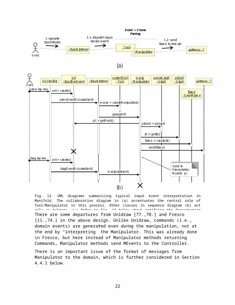
Typical event interpretation is illustrated in Fig. 12. Fig. 12(a) is a high-level abstraction emphasizing the role of a Tool/Manipulator tandem. Fig. 12(b) elaborates some details, but the actual code may still contain further details, and the reader should consult the source code for accurate information. Also, the diagram will be detailed and completed with several other diagrams below.As apparent from Fig. 12(b), the manipulator plays the key role in orchestrating
Fig. 11. UML sequence diagram of model visualization. Right-hand side shows the separate, periodic Display thread. The “gateway” marked with question sign is the Controller class introduced in Section 3.2 below.
15

the event interpretation, which is witnessed by the fact that most messages emanate from the Manipulator’s lifeline.
There are some departures from Unidraw [77,78] and Fresco [11,74] in the above design. Unlike Unidraw, commands (i.e., domain events) are generated even during the manipulation, not at the end by “interpreting” the Manipulator. This was already done in Fresco, but here instead of Manipulator methods returning Commands, Manipulator methods send MEvents to the Controller.
There is an important issue of the format of messages from Manipulator to the domain, which is further considered in Section 4.4.1 below.
Design Issue 2.5: Currently, manipulation sends events to the domain while the object is being manipulated. Most editors allow “preview,” through animation, and perform actions on the domain model only at the end of manipulation, which corresponds to the
Fig. 12. UML diagrams summarizing typical input event interpretation in Manifold. The collaboration diagram in (a) accentuates the central role of Tool/Manipulator in this process. Other classes in sequence diagram (b) act only as helpers. () Refer to Fig. 14 below about notifying the Presentation Models.
16

Manipulator.effect() method. The reason for our current approach is to be able to support real-time, synchronous collaboration. In this case, the actions of one user should be visible to all other users, if desired. Perhaps a different design can better solve this requirement?
Design Issue 2.6: The Selector tool combines several types of manipulation, as is customary in graphical editors. For example, the user can: (1) select individual glyph; (2) select several glyphs; (3) move the selected glyph(s) around; (4) resize the selected glyph(s) by dragging one of their handles; and, (5) clear the selections by clicking in the empty space. Cramming all these functionalities in a single class is not an elegant solution. Ideally, we should instantiate different tool/manipulator for different manipulation types. However, we do not know what type of manipulation will take place until the first “mouse press” event, which invokes grasp() on the Manipulator.
Notice that only the glyphs which are the children of the root glyph, i.e., the glyphs at the tree height equal one, can be manipulated individually. A glyph at a higher level is only manipulated along with its antecedent glyph at the level one. This is a customary choice in graphical editors. However, this policy may need to be changed in different editor types. For example, in the TreeViewer editor (described below in Section 3.1), we may want to be able to manipulate individual glyphs at any height of the tree.
2.2.2 Other Gesture TypesAs already mentioned, manipulation does not cover all types of interaction. Gestures, such as pointing or signaling by outlining signs/symbols, can occur without the characteristic manipulation cycle and there is an interesting design issue of handling them. Non-manipulative gestures can be produced by moving the pointing device around, without clicking the mouse buttons, e.g., Fig. 5. The Manipulator is expressly dedicated to parsing manipulation interaction, so it is not well suited for other types of interaction. Interestingly, this issue does not seem to have arisen in UniDraw [77] or Fresco [74].
Our solution is to handle the other input event types in the Tool. For example, the Linker tool needs to handle the mouse movement events. When the user intends to connect two glyphs by a Link, the user first moves the mouse cursor around to detect which glyphs have connectors and where are those positioned. Notice that at this time the user does not perform any manipulation. [The reader should recall or try in Microsoft PowerPoint using connector to easier appreciate the process being described here.]
To reveal additional information about the pointed-at glyph, the Tool may need to query the domain model. There is a property query frame designated for this purpose, Section 3.2 below.
This section describes the Manifold core. It largely covers what the developer building atop the Manifold needs to know. The rest what follows is a bulk, reflecting the idiosyncrasies of the underlying GUI toolkit.
17

Chapter 3Elaboration of the Basic Design
The process described in the previous section cannot take place in void, that is, it must occur within the context of a graphical user interface (GUI) toolkit, such as Microsoft Windows libraries, or Java AWT or Swing toolkits. This is where things get messy.
There are two key entities in the Manifold’s environment: the user and the domain application. As illustrated in Fig. 13, key objects that play the role of gateways between Manifold and its environment are Viewer and Controller.1
3.1 Interaction with GUI Toolkit and Input DevicesDescribe here also various presentation “models” and listeners.
3.1.1 Viewers
Design Issue 5.1: A desirable feature would be to be able to open a new viewer type, select glyph(s) in an existing viewer, drag them and drop into the new viewer. For example, if the new viewer displays some statistics, it would compute the statistics over the imported glyphs and automatically visualize this different aspect of the imported glyphs. For this, the application needs
to set “visibility filters” to prevent all glyphs being exposed in the new viewer. Who manages
1 This Controller should not be confused with the Controller from the Model-View-Controller design pattern. See discussion in Section 3.2.
Fig. 13. Manifold framework and its relationship to the contextual environment.
18

such filters? It should be a class in the presentation module, since the domain module should not care about the viewer(s).
Input Listeners: We could not perceive a benefit in specifying a common interface for input listeners. This class is tightly linked with the viewer implementation, so it can be specified only when the viewer implementation is known. On the other hand, this class is relatively independent of the input device, since we assume that it only receives input-event notifications from the device drivers. Its only role is to glue the device drivers (via the viewer) to the tools and manipulators associated with the viewer.
3.1.2 Controlling the Frame RateRe-rendering and re-displaying the scene graph is a resource consuming task and we need checks and controls on its invocation. The control of the rate of refresh, or “frame rate,” is centralized in the Display object. When a glyph’s property changes, it asks its parent viewer for a redraw, by calling Viewer.requestRedraw(). Individual property modifications are too fine granularity and may result in a “storm” of redraw requests. Hence, the request is recorded, but the actual redraw takes place only when the Display invokes Viewer.redraw(). The process is summarized in the right-hand size of Fig. 11.
Display in current implementation runs in a separate thread. It can perform the redraws periodically, at regular time instances that can be adjusted. Another approach, which is taken in the current implementation, is to have other objects notify Display about opportunities for redraw. Of course, the choice must be carefully performed, for otherwise we are no better than with fulfilling each glyph’s redraw request. Worse, there is extra overhead of an additional thread.
Our choice should be guided by the fact that view updates are initiated by the model(s), see Fig. 1 and 2. Since the Controller (described in Section 3.2) stands as the gateway between the domain and the presentation, it is selected to notify the Display about possible needed redraws. Similarly, presentation models (Section 3.1.3) should also notify the Display.
Design Issue 3.1: If you anticipate working only with small domain models (with correspondingly small number of glyphs) and you are thread-thrifty, you may decide not to run Display in a separate thread. Rather, Display is asked to perform redraws within the current thread. How to redesign Display to be able to make this choice (threaded vs. non-threaded) at runtime? Also, depending on the particular GUI toolkit used for the Manifold implementation, the toolkit may have mechanism for the framerate control. This should be possible to exploit from Display.
For the visual display of dynamic data, one of the most important considerations is maintaining suitably high frame rates. Typically, this is considered to be at least 20–30Hz [5]. Below this level motion appears discontinuous, and constraints on object interactions (such as collision detection and control in 3D graphics) may fail to be represented correctly due to the high inter-frame latency.
If we are to implement an advanced user interface with haptic force feedback [6], haptic output rendition imposes even greater demands on the system than visual displays. An important factor contributing to the correct perception of a collision with a solid, haptically-rendered surface is the amount by which the virtual surface can be penetrated. This is highly dependent on the latency inherent in the feedback system controlling the haptic device. Latency arises from two sources: the update rate of the device’s feedback loop, and communication delays. An update rate of at
19

least 1KHz [6] is considered to be necessary for solid contacts; below this rate objects begin to feel ‘spongy’, and if the rate drops too low, instabilities arise.
Design Issue 3.2: How to build into Manifold a mechanism to monitor the current frame rate and take corrective steps if it does not meet the user-specified quality-of-service? What corrective mechanisms can be implemented?
This may indicate that different viewers need different update rates. Moreover, different objects (glyphs) may need different update rates, as well.
3.1.3 Presentation ModelsPresentation models are formed after the Java Swing models. These are not actual domain models, but a refinement of the MVC pattern. A presentation model essentially maintains the state specific to the current viewing parameters or purely visual aspects of the glyphs. Examples are the viewing point, e.g., the position of the scrollbars on a window, or current choices on radio buttons. We already encountered shadow glyphs as purely presentation concepts that are not of interest to the application domain (Section 2.1.3 above).
Although these presentation concepts (viewing parameters and glyph decorations) are not of interest to the domain, we need to keep them consistent across multiple views, if there are multiple views. For example, in the current Manifold implementation, the viewers Viewer2DImpl and TreeViewer visualize the domain model in two different ways. When a glyph or several glyphs are selected (and highlighted) in one viewer, they should be highlighted in the other viewer, as well. For this, we need an equivalent of an application domain model, and that is what the presentation models are about.
Manifold currently defines two types of presentation models:
manifold.ToolsModel, which maintains information about the currently selected tool and whether or not the tool is of single-action type;
manifold.SelectionsModel, which maintains information about the currently selected glyphs in the viewer(s).
Fig. 14 shows how the tool/manipulator sets the selections model, which in turn notifies all the listeners registered for SelectionsEvents. In our case, these are manifold.swing.Viewer2DImpl and manifold.swing.TreeViewer. Notice that this diagram is conceptually similar to the one in Fig. 11, since both are depicting notification from the model to the glyphs.
Notice that the implementation of Glyph.setSelected() actually makes visible the Highlighter shadow glyph, rather than maintaining a boolean flag for this specific purpose.
The MVC design pattern postulates a single model and multiple views. The presentation models represent an extension of this paradigm, where we can have multiple models as well, each modeling different aspect of the task domain.
20

Design Issue 3.3: Intrinsic presentation models, such as javax.swing.tree.TreeModel maintained by javax.swing.JTree in manifold.swing.TreeViewer force us to maintain simultaneously two or more presentation models. This results in some inelegant solutions to keep them in synchrony and avoid interferences. An example is the helper field externalSelectionsChange maintained in TreeViewer to distinguish the notifications from the intrinsic model from those from manifold.SelectionsModel. An option would be to reuse the TreeViewer’s tree model in manifold.swing.Viewer2DImpl as well. This in turn requires using only leaf Glyphs and not composites such as manifold.impl2D.TransformGroup (because the composite is given by the intrinsic tree model). A leaf glyph would be held in a corresponding javax.swing.tree.DefaultMutableTreeNode as the “user object,” and stored/retrieved by set / getUserObject(). This is an option to consider for future work. Keep in mind, though, that Glyph has three different aspects (Fig. 9), and DefaultMutableTreeNode models only one of these!
3.1.4 Modes and Tool BoxWhat is referred to as a mode [31] in the user interface has the Tool object as the corresponding software concept. The mode is the current tool, which the user sets by selecting the appropriate button in the ToolBox or in some other manner.
Modes are generally considered as bad practice in user interface design.
There is no controversy about using modes on the system side—state is a legitimate software pattern [18]. The controversy is on the human side—the design of the UI appearance.
ToolBox is but one means of setting the current mode of a viewer. We could design a class which unlike ToolBox does not have visual appearance, if that is desired. This object monitors the keyboard strokes and sets the appropriate mode. When the viewer receives the keyboard focus,
Fig. 14. UML sequence diagram for updating the presentation model. This diagram is embedded in the one in Fig. 12. SelectorManipulator is inner class of the Selector tool, and the selections model can have arbitrary number of SelectionsListeners, as indicated by the loop.
21

this object gets activated to monitor for key combinations. A combination such as2 Ctrlcr sets the mode to allow creating rectangles; Ctrlce sets the mode to allow creating ellipses; Ctrlr sets the mode to allow glyph rotation; etc. These set the currentTool property of ToolsModel.
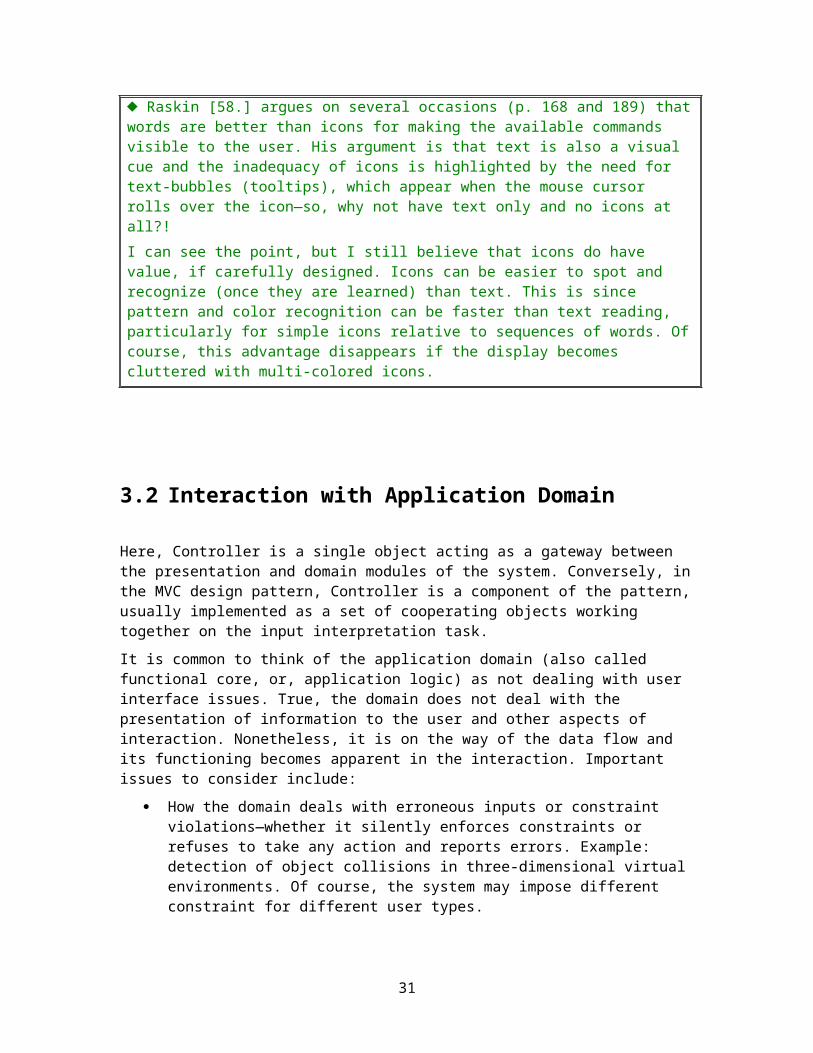
ICONS vs. TEXT Raskin [58] argues on several occasions (p. 168 and 189) that words are better than icons for making the available commands visible to the user. His argument is that text is also a visual cue and the inadequacy of icons is highlighted by the need for text-bubbles (tooltips), which appear when the mouse cursor rolls over the icon—so, why not have text only and no icons at all?!I can see the point, but I still believe that icons do have value, if carefully designed. Icons can be easier to spot and recognize (once they are learned) than text. This is since pattern and color recognition can be faster than text reading, particularly for simple icons relative to sequences of words. Of course, this advantage disappears if the display becomes cluttered with multi-colored icons.
3.2 Interaction with Application Domain
Here, Controller is a single object acting as a gateway between the presentation and domain modules of the system. Conversely, in the MVC design pattern, Controller is a component of the pattern, usually implemented as a set of cooperating objects working together on the input interpretation task.
It is common to think of the application domain (also called functional core, or, application logic) as not dealing with user interface issues. True, the domain does not deal with the presentation of information to the user and other aspects of interaction. Nonetheless, it is on the way of the data flow and its functioning becomes apparent in the interaction. Important issues to consider include:
How the domain deals with erroneous inputs or constraint violations—whether it silently enforces constraints or refuses to take any action and reports errors. Example: detection of object collisions in three-dimensional virtual environments. Of course, the system may impose different constraint for different user types.
The domain module may not be “aware” of the user, but the user is keenly aware of the domain (via the presentation). Therefore, the domain designer may need to take into account the impact of design decisions on the efficiency/effectiveness of interaction.
2 The notation for keyboard operations is due to Raskin [58: p. 35]. The down arrow symbolizes pressing the key named before the arrow and the up arrow symbolizes releasing the most recently pressed key. Thus, for example, Ctrlcr means: press Ctrl and hold it, next press and release c, then press and release r, and finally release Ctrl.
22
The reader may find it useful at this point to revisit the UML diagrams where the Controller appeared, to better master the design. In particular, see Figs. 6 and 7, where it was referred to as “gateway.”
3.2.1 Vocabulary of Slot VerbsThe controller implementation must specify a well-known list of the verbs that will be used in the event frames generated by the manipulators. The vocabulary is application-dependant and both manipulators and the application domain must know the meaning of these verbs. To be more precise, the manipulators must know how to parse the input events into the verbs (and other slots of the event frame). Application domain knows what action(s) to take in response to particular event frames. Of course, there is no need for manipulators to know neither what those actions are nor what their meaning is.
In our example implementation, the following verbs are defined in manifold.ControllerImpl:
public static final String ADD_NODE = "add";
public static final String DELETE_NODE = "delete";
public static final String SET_PROPERTIES = "setProperties";
public static final String PROPERTY_QUERY = "propertyQuery";
3.2.2 What is Messaged to the DomainIt is noteworthy that the event frames do not contain explicit information about the current operating mode of the user activity. For example, regardless of whether the operation is rotation or scaling or translation, the event frame only contains the glyph identity and its new transformation attribute. My assumption is that the domain does not need to know how the transformation came about—it is only interested in what the transformation is. If it for some reason needs to know what transformation is being applied, it is possible to decompose the transformation into constituent “pure” transformations by invoking Transform2D.extractComponents5(). However, some caveats apply, such as for non-commutative transformations (rotation and translation), or shearing transformation. (See further discussion in Section Chapter 4 below.)
Although I currently cannot come up with an example where the domain needs to know such details, the issue of frame descriptiveness deserves further consideration.
23

3.3 Class and Package Dependencies
The class dependencies are shown in Fig. 15. This diagram was generated manually, though, so I might have missed a few. Almost all current Manifold classes are shown, with the exception of ControllerImpl, Application, and some legacy classes in manifold.util.
Some dependencies are not shown. For example, SelectionsModel keeps reference to the Controller to get hold of Display when the selections are altered. The main purpose, though, is for the future use, to be able to send selection events to remote applications, e.g., in collaborative groupware applications. Also, the connection from Glyph to Viewer is not shown in this figure, but it is shown in Fig. 16.
The class inheritance diagram is shown in Fig. 16. PropertyEditor is shown without any descendants, since this is a work in progress, but there will be some, see Section 5.2 below. Each tool has a link to its corresponding manipulator, although the link is shown only from Rotator to RotatorManipulator, to avoid cluttering the diagram. Although the link is not shown, both viewers (Viewer2DImpl and TreeViewer) have visibility of the Glyph which is needed when managing the glyph tree (scene graph).
There is also ControllerImpl which implements the Controller, which is not shown since it serves only as a reference implementation.
Fig. 16. The class inheritance diagram of the current Manifold implementation. See the legend in Fig. 15.Fig. 15. The class relationships diagram of the current Manifold implementation. The inheritance relationships are shown in Fig. 16.
24

Fig. 17 shows the Manifold packages and their dependencies. Since all packages are nested in the root manifold package this diagram, strictly speaking, is incorrect, but easier to show the dependencies.
Fig. 17. Manifold package dependency diagram. () The tools package has small dependencies on swing.BaseTool and glyphs.Line, which are not shown for clarity.
25

Chapter 4Geometry and Transformations
4.1 Global, Screen, and Local Coordinate SystemsFig. 18 shows the relationships between different coordinate systems. The domain model is represented in the global (world) coordinate system. Normally, these would be Global Positioning System (GPS) coordinates of latitude and longitude. The screen window shows part of or the entire domain model, which is indicated by the size of the scrollbars. The screen coordinates are expressed in pixels and need to be converted to the world coordinates.
Glyphs can be grouped into multiple hierarchies and each grouping can have its own associated transformation. Because of this, we maintain glyphs in their local coordinate system. A prototype of the glyph is immutable, always centered in the origin of its local coordinate system, without any rotation, and with the fixed unitary dimensions. This is shown in Fig. 19(a). In order to create arbitrarily processed glyphs, we assign a transformation to the glyph, which transforms it relative to the transformation of its parent glyph. The root glyph of the scene graph also has associated transformation, which maps from the world coordinates to screen coordinates and vice versa. Example of transforming a glyph is shown in Fig. 19(b). Notice that the glyph itself remains unaffected by the transformation. The transformation is maintained separately and only applied during the scene graph traversal, Section 4.3 below.
Why maintain immutable prototypes? For example, java.awt.geom.RectangularShape has the method setFrame() to directly alter/transform the shape. Why not keep only the
Fig. 18. Coordinate systems for an ellipse glyph. Notice also the glyph’s handles.
26

shape reference and allow arbitrary means of transforming the glyph’s shape, not only using its associated transformation? The reason is that this would create confusion with the developer using the Glyph interface. The developer needs to keep track of the current transformation method. Plus, a general solution would have to be implemented anyway, to include the case where the developer want to use the exclusively the associated transformation.
The current method of keeping the immutable prototype and specifying the glyph’s geometrical properties using only the associated transformation offers a simple and uniform interface.
The entire viewer with its content can be transformed, as illustrated in Fig. 20. To achieve this, we apply the transformation to the root glyph of the scene graph.
4.2 Affine TransformationsAffine transformations are transformations in which parallel lines remain parallel. An affine transformation is any transformation that preserves collinearity (i.e., all points lying on a line initially still lie on a line after transformation) and ratios of distances (e.g., the midpoint of a line segment remains the midpoint after transformation). Translation, scaling, skewing, and rotation are affine transformations; perspective transformations are not. Here is a quick refresher on multiplying two affine transformation matrices:
Java 2D defines the class java.awt.geom.AffineTransform and the reader should check its accompanying documentation for details.
AffineTransform satisfies most of our needs and is used throughout the manifold.impl2D package, except that it does not provide easy access to the “pure”
Fig. 19. (a) Glyph’s prototype as represented in its local coordinate system. (b) Glyph transformed in the global coordinate system: positioned at (3, 5), width scaled to 6 and height to 4, and rotated by = 30 = /6.
27

component transformations. To compensate for this lack we define manifold.impl2D.Transform2D.
Typical graphical editor supports translations, rotations, and scaling of the geometric figures. A translation by (tx, ty) along the x- and y-axes is represented as:
A rotation by angle is represented as:
A scaling by (sx, sy) along the x- and y-axes is represented as:
An arbitrary affine transformation composed of rotation, scaling, and translation is then:
(*)
Notice that the order is important—translation must be applied the last—because translation and rotation are not commutative. The problem is illustrated in Fig. 21. Although this may appear as belaboring high-school geometry, it is very easy to overlook such minutia in a complex code and then spend lot of time hunting the petty bug.
Fig. 20. Example of a global transformation of the viewer. (a) Original. (b) The entire viewer with its content is transformed. Notice the size of scrollbars in (b).
28

If you applied the “pure” transformations as in (*) and then invoked AffineTransform.getScaleX(), what you obtain is the element m00 = sx cos, which does not represent the “pure” scaling transformation. Similarly, AffineTransform.getMatrix(double[] flatmatrix_) gives out the flatmatrix_ array with the 6 specifiable values of the 33 affine transformation matrix in the following format:
AffineTransform accessor method calls return the following:
If you assume that translation, rotation, and scaling were applied independently, i.e., as “pure” transformations, and you want to reconstruct the individual transformation components, one way to do it is:
Of course, we have to be careful with the inverse tangent (arc tan), since it is multivalued, and we
only consider the values in the range .
When setting transformations, the scale values should not be set to zero, since this yields infinite numbers for the inverse transformation. Instead, a minimum value of Double.MIN_VALUE = 4.9E-324 should be used.
Fig. 21. Illustration of the non-commutative nature of the translation and rotation transformations. (a) Original glyph. (b) Glyph rotated by = 30 = /6, then translated by (1.3, .07). (c) Glyph translated, and then rotated.
29

4.2.1 Line Glyph: Zero- and Negative ScalingThe line segment glyph presents an interesting case. As stated above, our convention is to represent simple geometric figures with immutable prototypes and derive an arbitrary sized figure by using an appropriate glyph transformation. An example is shown in Fig. 19. There are, however, some peculiarities in applying this approach to line segments. Namely, two extensions are required:
Negative scaling elements of the transformation;
Zero scaling elements of the transformation.
First, rectangular shapes are not oriented, so positive scaling transformations suffice to cover all the cases of interest. Unlike this, for line segments we may want to know the line’s orientation, that is, its starting and ending points. This is useful for the purpose of decorating the line with adornments such as arrows or other types of endpoint shapes. For this reason, we allow negative scaling as detailed below.
Second, we could try to control the slope of the line segment by the axial scaling components, similar to controlling the width/height of rectangular shapes. However, this turns out to be an awkward solution. A purely horizontal or vertical line has one of its dimensions equal to zero, and this presents serious problems when transforming the picking shape (Section 4.3.2 below) to the line glyph’s local coordinate system.
Our solution is to distinguish the two subtasks that need to be accomplished:
1. Messaging from the source of the property change, such as manipulator, about the new glyph’s transformation;
2. Shape re-computation during the glyph rendering (draw) traversal.
To support uniform messaging for all simple geometric figures, we allow for zero- and negative scaling parameters in the glyph’s transformation.
A more elegant solution appears to be to control the line’s obliqueness by the rotation angle . For this reason, manifold.impl2D.glyphs.Line overrides some of its base class methods. We maintain the immutable prototype as a horizontal line segment. The segment’s length is controlled by the larger of the two scaling elements. This is so because sy = 0 specifies a horizontal line and sx = 0 specifies a vertical line. The smaller scaling is silently enforced to be always the same as the larger one. This uniform scaling in both dimensions solves the problem with transforming the picking shape (Section 4.3.2 below).
To obtain an oblique line segment, we rotate the prototype by the corresponding angle. However, this does not show in the glyph interface. The interface remains consistent, so even the line slope can be specified with different scalings. This is particularly important in Manipulators, so the Manipulator methods need not discern between manipulating rectangular shapes and lines, Section 4.4 below. For this reason, the Glyph methods setProperty() and setCachedState() are overridden. In these methods, non-uniform scalings are intercepted and converted to line rotations. To account for the full range of rotations, [0, 360], we must allow for negative scaling. The reader should examine the source code for details.
Allowing for negative scaling may appear as a needless complication. However, in this way we retain the uniform external interface for controlling the Glyph’s geometry, that of affine transformations only. It should also be pointed out that negative scalings are never used in actual transformation. Rather, this is purely a messaging mechanism to communicate to glyphs their new orientation.
30

What if a line is simultaneously non-uniformly scaled and rotated? We ignore the rotation component and overwrite it with the one derived from the scaling components. In other words, the caller should take care not to send such ambiguous “messages.”
Problem: Does (sx, sy) = (10, 10) mean that the line should not rotated at all, or should it be rotated by 45?
4.3 TraversalsOne place where you regularly encounter transformations is during the scene graph traversal to perform operations on individual glyphs. Traversal implements the Visitor design pattern [18] for visiting a collection of glyphs. A traversal is passed to a glyph’s traverse operation and maintains common information as well as the stack of information associated with each level of the traversal.
Typical traversals are draw traversal, used in (re-)rendering the individual glyphs, and pick traversal, used in determining which glyph the user is trying to select for manipulation. Notice that these two traversals are explicitly supported in the Glyph interface, Fig. 8, via methods draw() and pick(), respectively.
4.3.1 Draw TraversalOutput rendition traversal for two-dimensional scene graphs is implemented as manifold.impl2D.TraversalDraw2D. The left-to-right order of scene graph nodes represents the spatial order of the corresponding glyphs in the depth axis. In other words, the glyphs that are encountered first will be rendered in the background and those that are encountered last will be rendered in the foreground. Altering the location of a glyph within the parent’s list of children will alter the rendering order of the glyph.
To render the glyphs, we use the Java 2D renderer java.awt.Graphics2D, which has a method draw(java.awt.Shape) for rendering simple geometric figures. We cannot invoke this method with the prototype shape of the glyph, since for all glyphs it would draw a small figure centered in the origin. We must first transform the glyph to the world, global coordinates.
There are two options to consider. One is to transform the glyph’s shape and then pass it to the graphics environment. The other option is to apply the global transformation on the graphics environment, method Graphics2D.setTransform(), and then pass the unaltered prototype glyph to the graphics for rendition. Both options have some drawbacks, so our implementation uses a combination of the two.
In the latter case of transforming the graphics environment before rendering, in cases where the scaling in different dimensions is unequal, glyph rendering results in undesirable effects as illustrated in Fig. 22. For this reason, we consider the former case, i.e., transforming the glyphs into the global coordinates before the rendition. One problem with this is that AffineTransform.createTransformedShape(Shape pSrc) returns the shape of the type java.awt.geom.GeneralPath, which is an approximation of the shape constructed from straight lines, and quadratic and cubic (Bézier) curves. This seems to be unnecessary complexity for simple geometric figures.
Our solution in GeometricFigure.draw() is to decompose the concatenated transformation obtained from the draw traversal into the rotation and translation+scaling components. The translation+scaling component can be easily applied to rectangular figures (see java.awt.geom.RectangularShape) and lines by just transforming their opposite corner
31
points. This is done in GeometricFigure.translateAndScaleShape(). Conversely, the rotation component is applied to the graphics environment and the shape is finally rendered.
Of course, this trick works only for simple geometric figures. Other glyph types must implement their own draw() method to suitably solve the problem.
4.3.2 Pick TraversalPick traversal finds the glyphs that intersect a given shape, usually a point or rectangle, specified in the world coordinates. It is used by the manipulator to determine what glyph(s) it should be currently working on, as indicated in Fig. 12(b). Conceptually, picking is like drawing and determining what glyphs intersect the point or region. Picking is unfortunately not as simple as Fig. 12(b) would imply. The detailed UML diagram which is embedded in the diagram of Fig. 12(b) is shown in Fig. 23. Pick traversal for two-dimensional scene graphs is implemented as manifold.impl2D.TraversalPick2D, which is passed in to the glyph’s pick() method. When pick() returns, the traversal contains a list of the glyph trails that were hit.
In our current implementation, the picking is decided based on the entire area of the glyph’s bounding shape. Thus, if a pick point falls within an empty figure contour, it is picked as if the contour were filled. The readers who may not like this choice are free to implement their own choice.
Let us assume the example shown in Fig. 19(b) above, and 100 pixels correspond to one unit in world coordinates. In other words, the scaling transformation (sx, sy) = (100, 100) is applied to the root glyph of the scene graph. Suppose the user selects the Selector tool and clicks at the location (500, 700) in the screen coordinate system. The location of the mouse click is called the pick point. In order to determine whether the glyph is “hit” by the picking point, we need to check whether the glyph’s bounding box contains the (transformed) picking point. This cannot be done straightforwardly by invoking pick() on the glyph since the glyph only knows about its local coordinate system, Fig. 19(a). The glyph’s bounding box is the rectangle with the opposite corners in points (0.5, 0.5), (0.5, 0.5). The straightforward answer is that the point (500, 700) lies outside the glyph’s bounding box.
Before invoking pick(), we must transform the coordinates of the picking point to the glyph’s local coordinate system. This implies applying the inverse of all the transformations starting with the root glyph up to the current glyph. The path transformations are maintained in the method visit(), as indicated by the note in Fig. 23. In our example, we have:
Fig. 22. Scaling the graphics unequally in different dimensions results in skewed rendering. Here glyphs are scaled doubly in the horizontal dimension, resulting in the varying line thicknesses.
32

The transformed pick point (0.46, 0.18) clearly falls within the ellipse’s bounding box, and the ellipse glyph invokes hit(this) on the pick traversal to register the successful pick.
As mentioned in Section 4.2.1, the affine transformation for Line glyphs cannot represent lines via scaling since axial lines require zero scaling in one dimension. This would present insurmountable obstacles in picking. For example, the pick point which is slightly off the line would be infinitely distant from the line when transformed to the line’s local coordinate system. For this reason, line segments must always have uniform scaling in both axes and represent their obliqueness via the rotation angle.
There is an interesting issue of transforming the glyph handles for the purpose of determining whether one of the handles is picked. We would like that the handles have fixed screen dimensions, in our case Glyph2D.HANDLE_DIM = 5 pixels. Obviously, we must transform
Fig. 23. UML sequence diagram for the pick traversal. The picking process yields the “current glyph,” which is the glyph that the Manipulator currently operates on.
33

this before checking whether the handle’s rectangle contains the pick point. The way we solve this is to apply the scaling component of the concatenated inverse transformation on the handle’s rectangle. If the scaling is different in different dimensions, we pick the smaller one. See the method Glyph2D.isHandlePicked() for details.
It is instructive to revisit the design issue in Fig. 10 after reading this section. How would the pick traversal work if the design in Fig. 10(b) were selected? What glyph(s) would be picked and which identifiers should be messaged to the application domain? [Recall that the glyph identifiers must be the same as the identifiers of the corresponding domain objects, so that the presentation and domain modules can meaningfully communicate.]
4.4 ManipulationAnother context where coordinate systems and transformations play a key role is glyph manipulation. It is important both in initiation the Pick Traversal, and during the physical deformation of the selected glyph(s).
In our terminology, manipulation primarily means altering the glyph’s geometry by applying different affine transformations. As such, manipulation affects only the glyph’s transformation property.
4.4.1 MessagingOur first choice is about the messages that Manipulator sends to the domain (via Controller) and, eventually, to Glyph. Our current Manipulators perform only spatial transformations on Glyphs, so it appears that an AffineTransform should suffice to message all the relevant information about manipulation.
There are some subtleties to this, particularly regarding the Line glyph, as described above. Example manipulation is illustrated in Fig. 25, which contains no rotation for the sake of simplicity. Recall that rectangular figures are specified with the opposite corners, denoted by points P1 and P2. As already explained, negative scaling signalizes that the figure has been flipped to a different quadrant relative to the anchor point. In addition, the transformation matrix sent in
Fig. 24. The problem of messaging via the glyph’s transformation. (a) One would expect that the active handle h5 maps to h5 as the user resizes the object through the anchor point h1. (b) This is what happens if the transformation’s scaling components are forced to always be positive.
34

an event frame for manipulating a line can contain zero scaling in one of the axes. However, the glyph itself (and the domain, too) preprocesses such transformation matrix before storing it. The reader should check Line.fixZeroScaling() for details.
In our reference implementation, the application domain is simulated in the class ControllerImpl, which simply bounces the frames back to the Manifold. However, a real application domain would quite likely not send the same frames back to the Manifold. A watch-list item is to ensure that the domain uses the same messaging conventions as in the Manifold.
4.4.2 SelectionGlyph selection receives the interaction point from the input device and initiates a Pick Traversal. Another option is to delimit a screen region and ask a Pick Traversal to identify all the glyphs within this region. In both cases, the pick shape (point or region) is represented in the world coordinates. As described in Section 4.3.2, the pick traversal transforms the pick shape to the glyph’s local system before testing for containment.
4.4.3 Animation and SimulationA key method that deals with the dynamics of glyph manipulation is Glyph2D.simulateHandleMovement(Point2D newPosition_). This method expects the handle’s new position, newPosition_, is given in the glyph’s local coordinates. This means that the whole simulation is performed on the glyph’s prototype. The key goal is to determine how the handle movement affects the glyph’s transformation property. The glyph’s new transformation is then exported in the return value of the method.
Currently, the transformation of the new handle position is performed in the Manipulator’s manipulate() method, see SelectorManipulator.manipulate(). For this, we must traverse the branch of the scene graph, from the currently manipulated glyph to the root, and collect the inverse transformations along the path. The concatenated inverse transformation is then performed on the point, and the point is passed to simulateHandleMovement(). The reader may wonder whether the branch traversal could be done in a more elegant manner by defining a new Traversal class for this purpose. For example, we could define something like HandleMovementSimulationTraversal?!
Presently, we felt that this would not be appropriate. The simulation is performed only by the selected glyph and all we need is a transformed point as input to the process. However, we could
Fig. 25. Glyph manipulation: resizing. It is assumed that P1 is the anchor point for the manipulation and P2 is being moved around. Scaling sy is negative to signalize that the figure has been flipped to a different quadrant relative to the anchor point.
35

imagine that there are several glyphs selected, where some or all of them could be in different branches of the scene graph. Then, manipulating a handle of one of them orchestrates manipulation simulation on all selected glyphs. Even Microsoft PowerPoint has such feature, but there is a user interface design issue associated with this feature. That is, having too many features may not be what users need, and the actual utility of this feature should be carefully considered.
Design Issue 4.1: Examine this option more carefully and consider designing a new traversal type (in addition to draw and pick).
Design Issue 4.2: In Glyph2D.simulateHandleMovement() and Line.simulateHandleMovement(), the way the new Glyph transformation is calculated is a quick-and-dirty solution. Check the code and devise a more robust calculation.
36

Chapter 5Controls, Dialogs, and Layout
5.1 ControlsMenus, toolbars, keyboard input, …
It is well-known that people use different words to name the same thing or concept [17], so, if possible, it is preferable to list the available choices as menu items.
5.2 Dialogs and Property EditorsWhen computer needs specific information, it initiates a dialog with the user. “Dialog,” as understood in graphical user interface design, is a conversational vignette in a limited domain, on a well defined topic, with a goal of extracting specific information from the user. The computer knows in advance what to ask and what are the options it can expect from the user as an answer.
Property Viewer displays only one glyph at a time—the one that is selected. It exposes the glyph’s properties for editing. Each property has a different editor, depending on the property’s data type, as illustrated in Fig. 26. There is only one property viewer instantiated per application. Every time a new glyph is selected, the old editors are emptied from the viewer, and the new set of editors are loaded.
The composition of the current manifold.swing.PropertiesViewer implementation is shown in Fig. 27. The glyph-specific property editors are contained in the PropertyEditorsPanel, which is specific to different glyph types and is re-loaded every time a new glyph is selected. PropertyEditorsPanel contains multiple property editors, which are subclasses of javax.swing.JComponent.
What if the selected glyph is non-leaf, inner glyph? In this case we can assume that the user wants to edit simultaneously all the properties that are common across all the leaf glyphs that are descendants of the selected glyph. Hence, the viewer first inquires the leaf glyphs for their editable properties to determine the set of the common properties. Notice that the information about the editable properties is known only to the glyph’s PropertyEditorsPanel, not to the glyph and not to the corresponding domain node, so the property viewer in fact inquires the PropertyEditorsPanel.
By the same token, we may extend property editing to the case of multiple selected glyphs. In other words, the property viewer again queries all the leaf glyphs to determine the common properties. As already mentioned in different contexts, such complex features may look fancy, but the important question is what value the present to the user. This issue must be carefully considered before investing effort in implementing such features.
37

As noticed above (Section 3.2), messaging about the attribute changes is transparent of the source. Dialogs communicate the change in the same way as Manipulators do. In fact, dialog-type interaction could entirely substitute direct manipulation, but for some purposes it would be awkward, if not impossible, to produce so many messages in such a short time. Direct manipulation has an advantage of allowing a quick compare-and-correct experimentation until the desired value is found. However, if the exact desired values of glyph properties are known in advance, then it is superfluous to experiment with direct manipulation.
5.3 LayoutA layout manager is an object that controls the size and position (the tiling layout) of components inside a Container object. For example, a window is a container that contains components such as buttons and labels. The layout manager in effect for the window determines how the components are sized and positioned inside the window. The act of physically placing interface objects on a window, to achieve a uniform and aesthetically pleasing look is performed by sophisticated internal algorithms.
Layout and the actual Java widgets used in composing a Manifold interface are controlled externally by specifying several XML configuration documents. These documents are formatted as specified by java.beans.XMLEncoder. With this facility, the Manifold can be assembled in different ways, without editing the Java source code. (But, you have to edit the XML source code, which is not fun either.)
The key issues here are:
Economizing the screen real estate
Reducing the user effort in locating the viewers and controls
Presently, there is nothing in Manifold to manage layout. It is left to the designer to employ the suitable widgets for layout management and arrange the UI components around the screen. An
Fig. 26. Example of a property editing dialog box. Property editors allow editing the property values.
38

example is given by the XML application specification file draw2D.xml, which is part of the Manifold distribution. The application assembly is depicted in Fig. 28.
The class relationships are shown in Fig. 15, but most of the actual object instance relationships are established dynamically, at the “booting” time, and can be changed at runtime. It is noteworthy that no class in the system knows what particular objects contained in different XML files are available. Tools/Manipulators, Glyphs, PropertyEditors, Menus, any and all of these can be seamlessly added or removed at runtime without the rest of the system knowing about such alterations. The runtime links between the objects are made via the property mutator (setter) methods in the given XML document.
GlyphFactory receives “orders” to build new glyphs specified by the glyph’s logical name, but the GlyphFactory itself does not know the actual classes since it relies on a look-up table: given the glyph’s logical name as the key, it finds the Java class as the corresponding value.
The Java XMLEncoder may not be the best means for user interface description, but we use it because it is ready and available. Other options are the use custom interface builders, which would also require new UI markup language, such as the one in [35].
Automatic layout management is considered to some extent in [50]. Another work of interest is [52].
Design Issue 5.1: How to control the arrangement (layout) of “inner” windows, such as ToolBox, TreeViewer, and PropertiesViewer, externally from the XML configuration file? Also, instead of having these as inner panels, perhaps we can have a fixed layout where these are external panels, placed around the Viewer2DImpl panel, such as in, e.g., Eclipse.
Fig. 27. Composition of a property editing dialog box: (a) The screen rendering; (b) The UML class diagram.
39

Design Issue 5.2: Build a wizard to edit the XML source code to assemble the Manifold components into a specific configuration. There are many such wizards already available. Check, e.g.,
R. Eckstein, “Creating Wizard Dialogs with Java Swing,” Copyright 1994-2005 Sun Microsystems, Inc., February 10, 2005. Online at: http://java.sun.com/developer/technicalArticles/GUI/swing/wizard/index.html
Fig. 28. Application assembly is performed by the class Application from several XML documents.
40

Chapter 6Human Factors in Interface Design
So far our focus has been on software and little has been said about the UI appearance design.
Software engineers must often take responsibility for designing the appearance of the user interface as well as for the design of the software to build that interface. Since interfaces are intended for humans, it may be useful to learn few things about human perception and cognition.
With visualization there is an issue of not only the amount of information conveyed in a display, but also the means of conveyance. If the means selected fits with the way the human brain works, then it will open the floodgates, and the same information can be conveyed in a much shorter time.
Consideration of human characteristics and capabilities is important not only to improve performance, but perhaps even more important is to help avoid the so called “user errors,” which most often arise due to a poor UI design. A poorly designed user interface will likely make it difficult for the user to access some of the system features and confuse the user into making mistakes.
6.1 Brief Overview of Human Perception
Sensation is an act of concentrating on mental variables without attributing them to the object, i.e., abstracting features without thinking of a specific object. For example, yellow color without thinking of banana. Sensations (qualia) are the simplest things. Perception, on the other hand, takes place the very moment we attach the attribute to an object. A popular belief at the beginning of the 20th century by structuralists was that from sensations “atoms” you can build “molecules” of perception.
Example:
Sensations: “I see a red color.” or “I taste sweetness.”
Perceptions: “The rose looks red.” or “The sugar is sweet.” (Since rose and sugar are “external.”)
The sensationalist would look how brighter or darker is some part of the image, whereas the perceptionalist would look how illumination edges are created. Pure sensations, Ganzfeld in German, are difficult to create.
An important concept in perception is the figure/ground phenomenon. Certain patterns tend to be seen as the “thing” while the rest is perceived as the “substance.” So, instead of figure/ground, we can call this phenomenon as: something vs. nothing. It should be noted that here “figure” is a misleading term. The pattern need not be a familiar one, but can be of an abstract or amorphic design. Figure refers to the fact that we attend to this perceptual organization while other organizations pass unnoticed. Once something appears in the consciousness it becomes a “thing” and the rest—ground—is nothing.
41

The purpose of this mechanism is to shut down unimportant information. When we walk on the street, we do not remember everything afterwards because we do not pay attention. If we pay attention for some reason, we will remember it. (There are some exceptions with people who have very good memory, though.)
The Gestalt school of psychology [59] studied extensively those factors which influenced the emergence of a figure. These studies were usually carried out on line drawings of relatively simple design and the terminology used (such as good gestalt, closure, good continuation) was more qualitative than quantitative. A well-known example is Rubin’s figure, which flips alternatively between an urn and faces.
People have different physical capabilities: some people are better than others at hand manipulation; others have higher visual acuity or sensitivity; some people are color-blind or may have more serious disabilities; etc.
6.1.1 Focal AttentionThe focal attention is regarded as a separate mechanism that can inspect many processing stages at will, but not the earliest ones, and probably even most of the higher perceptual stages and states cannot be attended. Julesz [32] stresses the metaphor of focal attention as a shifting searchlight. This can be illustrated by preattentive (parallel) texture discrimination vs. serial scrutiny by focal attention. In Fig. 29, the X’s pop out from the L’s as a parallel process, i.e., almost instantaneously, independently of the number of elements. Conversely, it requires time-consuming element-by-element scrutiny to detect an array composed of T’s among the L’s. If we were not told about it, we would probably never see it. This is a figure/ground effect.
Focal Attention (FA) determines where to move the fixation of the eye. If there is a texture gradient, we will observe where the gradient is, but not what it is. We do not know what it is, we know where it is, and it draws FA, so we can determine what it is. This is the searchlight metaphor.
There are several metaphors of focal attention:
Fig. 29. Preattentive (parallel) texture discrimination vs. serial scrutiny. The rectangle formed by X’s among the L’s pops out effortlessly, while finding the rectangle formed by T’s among the L’s requires an element-by-element search.
42

Focal attention as a searchlight. The searchlight metaphor acts as an early filter that takes out an area or item and ignores its surround and applies further processing there. The figure/ground phenomena are simple perceptual examples of how the figure is elevated to the status of a “thing,” and the ground becomes ignored as “not a thing, or nothing.” The searchlight and filter metaphors are all-or-none. The selected target is highlighted, while the rest disappears in the dark. It is in Helmholtz’s tradition. We can make afterimage for several hours, and we see what FA can do. The trouble with this technique is that the image fades. By strobing we can revoke it. We can find out how searchlight of FA goes around.
Distributed focal attention model (William James). Limited resources model: we put some resources at some position, and then we have less for the remaining positions. James is even asking: Is it possible in addition to one thing to scrutinize two things or even three? The limited resources metaphor establishes a gradual hierarchy, based on dwindling resources. The first, or the most important item gets the most attention, while at repeated second, third, etc., glances the attentional strength becomes less intense, and slowly disappears.
Both models are metaphors. In physics we have experiments; here in psychophysics we have metaphors, such as searchlight. Metaphor is a tool which brings things back to heuristics by using the terms and concepts drawn from human experience. Metaphor has advantages:
- Easy to remember (mnemonic value);
- Maps something unknown to known. It could be from complicated to simpler. It could be to even more complicated, but familiar!
There is no experiment that will tell apart searchlight of attention from the distributed attention of Wundt and James. If one could ever look at the brain as the areas of attention light up by changes in metabolic activities (but at real-time speeds, unlike our present PET and NMR techniques), perhaps one could see whether only one stream of neural activity is prominent, or several streams become activated with different strengths. Cognitive psychologists prefer distributed attention model.
There appear to be two purposes of focal attention:
Disinhibition: FA disinhibits the attended region (which is drawn by a texture gradient) and isolates it from inhibiting surround;
Inspection: FA submits it for inspection by the form recognition mechanism.
That goes much faster than eye movements. If texture gradient does not help, then we can do with FA the same as if texture gradient has drawn it.
In summary, it appears that early vision can be subdivided into a preattentive system (resulting in instantaneous pop-out), and an attentive system (based on element-by-element scrutiny). In some important cases this dichotomy is not simply the two extreme points of a continuous psychometric curve, but represents two distinct processing modes, perhaps parallel versus serial mechanisms, or some other qualitatively distinct information processes.
Pop-out helps just to know where not what it is.
My impression is that nobody really knows how attention works. The current models are simple metaphors, which help us understand what is known so far.
O’Regan’s work on change blindness
43

6.1.2 CognitionGeorge Miller’s famous “seven plus or minus two” hypothesis was derived from his finding that human short-term memory can store about seven items at a time [40]. The short-term memory is what we use, for instance, to remember a telephone number just long enough to look away from the paper on which it is written to dial the number. Recall how many times you had to look back in the middle of dialing, particularly if you are not familiar with the area code, which makes the number a difficult 10 digits!
Notice that the Miller’s hypothesis talks about seven “items,” which could be anything, such as numbers, faces, people, or communities—as we organize information on higher levels of abstraction, we can still remember seven of whatever it is. This is called chunking.
It was found that in vision, the magic number is closer to four, rather than seven. Because of a limited short-term memory, if you present the user with too much information at once, he or she may not be able to intake all of it. It is as if we had some primitive brain which can work for up to four things. Chunk is a new level of an item, out of which we can have four chunks of four things.
In addition to focal attention, which scans objects about five times faster than one can do with eye movements, there is another way to increase information intake. This is by learning increasingly complex chunks. This kind of learning is a high-level process. If one is very briefly shown, say, five pebbles, probably their number can be guessed without error, while with more pebbles mistakes will be made. However if the pebbles are arranged in chunks of regular pentagons, one can count up to five pentagons without error, and thus can count a total of 25 pebbles.
People make mistakes, especially when working under stress. A misbehaving or non-intuitive system is a great source of stress. Warning and error messages and alarms put additional stress, thus increasing the chances that the user will make operational errors.
6.2 General Interface Lessons
Some of the common recommendations about interfaces include:
Visibility: Every available operation/feature should be perceptible, either by being currently displayed or was recently shown so that it has not faded from short-term memory. Visible system features are called affordances [49];
Transparency: Expose the system state at every moment. For example, when using different tools in manipulation, it is common to change the cursor shape to make the user aware of the current manipulation mode (rotation, scaling, or such);
Consistency: Whenever possible, comparable operations should be activated in the same way (although, see [20] for some cautionary remarks). Or, stated equivalently, any interface objects that look the same are the same;
Reversibility: Include mechanisms to recover a prior state in case of user or system errors (for example, undo/redo mechanism);
Intuitiveness: Design system behavior to minimize the amount of surprise experienced by the target user (this is where metaphors and analogies help);
44

Guidance: Provide meaningful feedback when errors occur as well as context-sensitive user help facilities.
Obviously, the software engineer should not adopt certain design just because it is convenient to implement. The human aspect of the interface must be foremost.
Experience has shown that, although users tend at first to express preference for good looks, they eventually come around to value experience. The interface designer should, therefore, be more interested in how the interface feels, than in its aesthetics. What something looks like should come after a very detailed conversation about what it will do. There are different ways that interface developers quantify the feel of an interface, such as GOMS keystroke model [30], Fitt’s Law, Hick’s Law, etc.
6.2.1 Hierarchical Information VisualizationBecause of the limitation of human ability to attend to about seven items at a time, it is a good idea to represent information in a hierarchical, or multiscale, or multiresolution fashion. Natural images usually present such hierarchical information at once: we first get the overall idea of what the scene is about and what are the key objects in it; then we attend to local chunks of objects.
If the designer is unable to conceive such a visualization for an abstract dataset, he or she should at least provide for drill-in, as in so-called zoomable interfaces [4,58]. The problem is that the context is lost.
45

Chapter 7Extensibility and Reusability
Our goal is to protect the UI developer from dealing with complexities of the GUI toolkit and the application domain. We hope that the developers using Manifold will be inspired to build on following the suggested design patterns. With that goal in mind, we consider generic parts which can be reused in different application contexts, and what needs to be interchangeable.
I am not enthusiastic about reusing any of the components of the Manifold framework in other frameworks. If such opportunity arises, that is great. However, my main concern is: what parts of the framework can be reused within Manifold but in different application contexts, and what parts need to be substituted to suit the task at hand.
I believe that Manifold is extremely lightweight and reusable user interface framework. Fig. 30 shows the “onion” structure, where the developer can start reusing at any layer of the “onion.” If you choose to start with the core interfaces only (the package manifold), you are only using the high level design. The package manifold.impl2D offers basic two-dimensional geometry functions. Instead of this, you could build on top of the core interfaces and implement an equivalent package to be used on small devices. The package manifold.swing offers layout and controls implemented using the Java Swing GUI toolkit. The entire current implementation offers a simple two-dimensional drawing editor.
A major advantage of the Manifold design is that it is completely self-contained presentation module, implementing the Controller/View components of the MVC pattern. It can be attached to an arbitrary domain, since it assumes no knowledge of any domain classes or interfaces. The manifold classes only know that the Controller class acts as a gateway to the domain. On the other hand, the Controller class exposes all the relevant information flows within the presentation module. It is via this gateway that events from the presentation module can be intercepted and distributed as needed, and new events can be injected into the presentation module.
Fig. 30. The “onion” structure of the Manifold packages.
46

Manifold really acts as a syntactic glue to connect different XML documents and Java classes which define different visualizations and input interpreters, i.e., semantics. Its intelligence is in knowing what can be connected to what and routing messages between those software objects which perform the actual meaningful processing.
If you are a software developer planning to use Manifold, assuming that you have carefully read once this entire document, the quick guide on getting around is illustrated in Fig. 31.
7.1 Development ProcessSo, you may ask, where does this fit in the development process? Software engineers tend to neglect the user interface issues and bring in the user interface designers only at a late stage. Conversely, texts on interaction design recommend starting with user interface considerations early on [55]. Design of the user interface appearance should be done along with the application development.
In accord with Raskin [58], I tried to separate physics from semantics of the user interaction. There is so much in UI that is common across all UIs and independent of the semantics of the underlying application. Manifold offers uniform handling of physical manipulations; it funnels all those manipulations to a single point (Controller object) and there it exposes their outputs.
An application developer who wishes to use the Manifold as the application’s interface needs to define the semantics of the manipulations. This is done by “translating” the frames at the meeting point of the interface and the domain module, i.e., the Controller object. As already mentioned, this can be done via XSL scripts.
The goal is that the UI developer will only have to implement the parts that he/she is interested in, relying on the Manifold framework for the rest. Therefore, I would argue that the user interface development can occur at any point of the development process. Of course, the interface designer should coordinate with the application developer about the semantics of the user operations.
Fig. 31. Entrance points for different types of developers.
47

7.2 Tools, Manipulators and ControllerExample Tools and associated Manipulators provided in the current application can be taken out and replaced with other Tools/Manipulators in different application contexts. Fig. 32 summarizes the key characteristics of this tandem. The developer must follow the manifold.Tool and manifold.Manipulator interfaces and implement their desired functionality for the grasp-manipulate-effect manipulation cycle.
The tools normally know very little or nothing about the glyphs they operate upon. For example, the Creator tool does not import any Glyph interface at all. Deletor imports Glyph to handle the list of glyphs scheduled for erasure. Both Selector and Rotator import Glyph2D to access the glyph’s transformation and TransformGroup to obtain the picking traversal service. Selector also uses the handle-movement simulation service. Obviously, this is a very basic knowledge and a broad range of spatial glyphs can be manipulated by the existing tools/manipulators. We believe that this demonstrates high degree of decoupling between the tools and objects on which they operate (glyphs).
The implementation of the Controller interface is also related with tools/manipulators. This is because the controller knows the action verbs of the event frames that the current application domain supports. The manipulator sets those verbs when creating the event frames for the domain.
7.3 Glyphs and ViewersWe believe that it is relatively easy to extend the “vocabulary” of glyphs that can be placed within the viewer canvas. Our glyphs pursue middle ground between what Bederson et al. [4] call polylithic and monolithic approaches to structured graphics. We introduce “shadow glyphs” that can be composed with visual glyphs to provide additional appearance or functionality. Although not entirely independent as nodes in polylithic approaches, the shadow glyphs nonetheless provide separation of concerns and structured graphics aspects.
Glyphs know nothing about the tools/manipulators that operate on them. Generally, glyphs have minimal coupling with the rest of the Manifold framework.
Glyphs are tightly coupled with the Viewer in which they will be displayed, and the viewer may provide “layout management” for them.
7.4 Input Device ListenersAs people start to use their PCs more, they start to identify ways in which they want to use peripherals for different tasks. Task specialization has led to a variety of keyboard and mice on the market; but, there are emerging more exotic interface technologies.
Fig. 32. The main inputs and outputs of a Tool/Manipulator component.
48
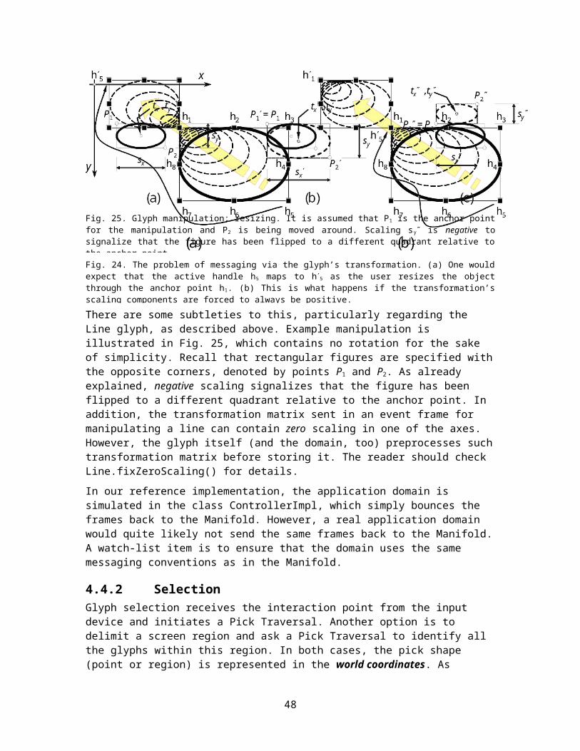
As pointed out in Section 3.1.1 above, we found no advantage in specifying a common interface for input listeners.
7.4.1 SpeechA speech interface can be used to directly issue commands to the domain. However, it could be used in a direct manipulation mode, such as commanding: “Pick up the object X and start moving it north-east … keep going …keep going … turn to the right … stop.”
Although there has been a great effort invested in trying to incorporate speech in human-computer interfaces, speech continues to play a minor role in HCI, and not because speech recognition is still imperfect. This may appear surprising, given that speech and language play the central role in human communication. Some challenges of speech-based interfaces are considered in [12,67]. The greatest problem, in my opinion, is that the computer is very unintelligent. All programs, despite their apparent complexity, have relatively simple knowledge and intelligence. Moreover, there is no knowledge sharing across different programs—all programs work independently—the only sharing is via the clipboard!
Because of this, humans still operate the computer, like a tool, rather than communicating to it like another intelligent being.
7.4.2 Cyber Gloves and Pointing Devices
7.5 Small Devices and Information AppliancesSpecial issues are present with small devices, such as mobile phones and handheld computers.
Ref. [51]
49

Chapter 8Complexity and Performance
Software engineering is deceptively simple. People are usually impressed by processes/tasks where in a single step they have to make a great leap. Having to handle simple tasks is usually and unchallenging, perhaps even boring, regardless of the number of tasks, and it defies believing that such work can be complex. Thus, it is hard to argue that complexity can arise from having to deal with many simple things.
But it is well known that humans cannot be conscious of more than one task at any moment, regardless of the task difficulty (Card, Moran & Newell, 1983). We can simulate simultaneous accomplishment of multiple tasks that require conscious control by alternating our attention between tasks, attending now to one, then to the others. We can achieve true simultaneity when all but at most one of our tasks become automatic.
8.1 Design ComplexityThe designs usually start elegant—nobody well-intentioned devises shabby design—but as the number of classes grows, the complexity inevitably creeps in. As an economist would say, the bigger the organization becomes, the greater free-rider problem it has. If the barriers to entry become too low—and the ties among the members become tenuous—then an organization as it grows bigger becomes weaker, more disorganized.
Design complexity is an important issue about any software product, but I’m not aware of good and generally accepted quantitative measures of software complexity. For this reason, some ad-hoc measures are devised.
When considering complexity of a software package, we are not really interested in knowing how complex it is, nor how to make it more complex. What we really want to know is, is this the simplest/smallest program that solves the problem we are set to solve? This is the Minimum Description Length problem [24]. We should not like redundancy and avoidable complexity. So, our aim is to maximally compress the program and find its smallest representation in the information-theoretic sense. Of course, to compare two designs, we need to have a measure of complexity.
The wisdom of investing effort in seeking the smallest program for the task may be questioned in this age of cheap processing power and storage memory. But, I am not proposing code compaction for the sake of computers; rather, it is for the sake of people who will have to read this code.
Fig. 15 and 16 are combined into Fig. 33, which shows the connectivity graph for all the classes in the current Manifold implementation. Again, this diagram was generated manually, so I might have missed a few links. Not shown are the links from GlyphFactory to the five leaf glyphs (Rectangular, Line, Link, Text, and Picture), to avoid further cluttering this already
50

busy diagram. The utility class Application (symbolized by “A” in Fig. 33) has no links to other classes. The utility class Debug (symbolized by “Dg”) is used for debugging purposes, and although there are many other classes pointing to it, the links are not shown since they are inconsequential. The classes PropertyEditor (“PE”), PropertiesViewer (“PV”), and PropertyEditorsPanel (“PEP”) are shown without links since they are not yet implemented. Eventually, there will be links to and from these classes.
The chart in Fig. 34 plots the number of classes having different counts of input-, output-, or all links to other Manifold classes. Only the connections to Manifold classes are shown; the connections to Java classes are not shown. Inheritance link is counted as input link on the base class and as output link on the derived class. Bi-directional associations are counted both as input- and output links, i.e., twice in the count of all links, for both of the associated classes.
As expected, most of the classes have very few links and vice versa: very few classes have many links. This characteristic was observed for very large software packages, as well [76].
The total number of links is 188 and, given the total of 53 classes, there is about 3.6 links per class, on the average. Of course, as Fig. 34 shows, the links are not evenly distributed. The Manipulator leads the way with 12 links total, Viewer is the second with 10 links total, then Tool and Glyph have 8 links total each, etc. Obviously, these are central classes, so it is to be expected that they should have greater connectivity than any others.
0
5
10
15
20
25
30
0 1 2 3 4 5 6 7 8 9 10 11 12
Count of Links
Num
ber o
f Cla
sses
Input Links
Output Links
All Links
Fig. 34. Statistics of the connectivity of all the classes in the current Manifold implementation.
Fig. 33. Class connectivity graph for all the Manifold classes.
51

Although the current design is arguably lightweight and simple, the question of how it would look once it becomes a feature-laden interface can be settled only by further developing of the current framework.
8.2 PerformanceNo quantitative performance measurements have been conducted so far.
Design Issue 7.1: The “booting time” of the application is always of concern. Consider the booting time of Adobe Acrobat. I always wonder whether there was a better way to load all those modules that I almost never use anyway, as I am waiting, seemingly forever, just to view a PDF document. Perhaps we should consider doing only basic initialization and let the user start working right away. The rest of the initialization can run in a separate background thread.
52
Chapter 9Discussion and Conclusions
Many of the user interface ideas that you may have seen articulated elsewhere, you will find implemented in Manifold.
The Manifold framework presented here provides a domain-independent implementation of a presentation module. It is meaningful to state that this UI design acts as a translator and interpreter from the language of human (gestures) to the language of computers. It translates the user’s pointing gestures into action frames that are delivered to the underlying application domain. The conversational metaphor is exploited throughout the framework.
Gesturing and manipulation in particular implies spatial representation of the domain data. This may appear to restrict the applicability of direct manipulation only to spatial domains that contain elements with spatial attributes (locations and dimensions). Examples are graphical editors of geometric models.
However, this is not necessarily the case, as illustrated in Fig. 3, where files and folders are not geometric objects and spatial location has no meaning for an electronic document. But, it is true that the visualization of the domain must be spatial, rather than the domain itself. Visualizing the files and folders as spatial objects helps the user to easier interact with the file system and keep track of the documents.
The Manifold framework provides a natural growth path to the complete fully-functional systems, such as the PowerPoint graphical editor. Another example application that is suitable to build on the Manifold is the virtual biology laboratories [72]. Those are already built using an earlier Manifold version and porting them to the current implementation would not require a major effort.
In summary, applicability of direct manipulation does not depend on the spatial nature on the underlying data. All that matters is that the developer can come up with a spatial representation of the domain.
Question/Criticism 5.1: How general is this design? Is it only good for “graphical editors”? cf. ref. [77,78]. To counter this, we use Tool/Manipulator to implement DragTree, as in OverlayManager.
9.1 Related Software PackagesFresco: http://www.fresco.org/
InterViews: http://www.ivtools.org/ivtools/interviews.html
Berlin: http://www.berlin-consortium.org/
Piccolo: http://www.cs.umd.edu/hcil/piccolo/
Amulet: http://www.cs.cmu.edu/~amulet/
53

9.2 BibliographyGeneral literature on user interface design [2,66], although a bit outdated.
Light introduction to interface design [55]
Raskin [58], though at times argumentative and purporting ground-breaks, I found it more useful than most other UI books I read. It is mostly about interface design, little on software engineering, but articulates many sound design ideas that have informed the Manifold design.
Light introduction to software engineering [36]
Design patterns [18,7], also insightful is [14]
Information visualization [79,9,70]
Java books [14,73]
Java 2D API review [33]
Computational neurobiology of pointing and manipulation [62]
History of graphical user interfaces [1,42,56]
Some websites of interest (last checked August 2005):
http://www.useit.com/ [useit.com: Jakob Nielsen on Usability and Web Design]
http://www.jnd.org/ [Don Norman’s jnd website]
http://www.asktog.com/ [AskTog: Interaction Design Solutions for the Real World]
http://www.pixelcentric.net/x-shame/ [Pixelcentric Interface Hall of Shame]
http://citeseer.ist.psu.edu/context/16132/0
http://www.sensomatic.com/chz/gui/Alternative2.html
http://www.derbay.org/userinterfaces.html
http://www.pcd-innovations.com/infosite/trends99.htm [Trends in Interface Designs (1999 and earlier)]
http://adb.sagepub.com/cgi/content/refs/11/2/109 [Giorgio Metta: Better Vision through Manipulation]
http://www.devarticles.com/c/a/Java/Graphical-User-Interface/
http://www.chemcomp.com/Journal_of_CCG/Features/guitkit.htm
http://www.google.com/Top/Science/Social_Sciences/Psychology/Cognitive/People/
http://nivea.psycho.univ-paris5.fr/ (J. Kevin O’Regan: change blindness)
54

References
1. Answers.com: History of the graphical user interface, Online at: http://www.answers.com/topic/history-of-the-graphical-user-interface
2. L. Bass and J. Coutaz, Developing Software for the User Interface, Addison-Wesley Publishing Company, Inc., Reading, MA, 1991.
3. M. Beaudouin-Lafon, “Instrumental interaction: An interaction model for designing post-WIMP user interfaces,” Proceedings of the ACM SIGCHI Conference on Human Factors in Computing Systems (CHI '00), p.446-453, The Hague, The Netherlands, April 2000.
4. B. B. Bederson, J. Grosjean, and J. Meyer, “Toolkit design for interactive structured graphics,” IEEE Transactions on Software Engineering, vol. 30, no. 8, pp. 535-546, August 2004.
5. F. P. Brooks, “What’s real about virtual reality,” IEEE Computer Graphics and Applications, vol. 19, no. 6, pp. 16-27, November/December 1999.
6. G. C. Burdea, Force and Touch Feedback for Virtual Reality, John Wiley & Sons, Inc., New York, 1996.
7. F. Buschmann, R. Meunier, H. Rohnert, P. Sommerlad, and M. Stal, Pattern-Oriented Software Architecture: A System of Patterns, John Wiley & Sons, Inc., New York, 1996.
8. P. R. Calder and M. A. Linton, “Glyphs: Flyweight objects for user interfaces,” Proceedings of the 3rd ACM SIGGRAPH Symposium on User Interface Software and Technology (UIST), pp.92-101, Snowbird, UT, October 1990.
9. S. K. Card, J. Mackinlay, and B. Shneiderman, Readings in Information Visualization: Using Vision to Think, Morgan Kaufmann Publishers Co., San Francisco, CA, 1999.
10. S. Chatty, S. Sire, J.-L. Vinot, P. Lecoanet, A. Lemort, and C. Mertz, “Revisiting visual interface programming: Creating GUI tools for designers and programmers,” Proceedings of the 17th Annual ACM Symposium on User Interface Software and Technology (UIST '04), pp. 267-276, Santa Fe, NM, October 2004.
11. S. Churchill, “Structured graphics in Fresco,” C++ Report, vol.7, no.3, pp.61-68, March/April 1995.
12. L. Deng and X. Huang, “Challenges in adopting speech recognition,” Communications of the ACM, vol. 47, no. 1, pp. 69-75, January 2004.
13. S. W. Draper and D. A. Norman, “Software engineering for user interfaces,” IEEE Transactions on Software Engineering, vol. 11, no. 3, pp. 252-258, March 1985.
14. B. Eckel, Thinking in Java, 3rd Edition, Prentice Hall PTR, Upper Saddle River, NJ, 2003. Online at: http://www.mindview.net/Books
15. F. Flippo, A. Krebs, and I. Marsic, “A framework for rapid development of multimodal interfaces,” Proceedings of the 5th International Conference on Multimodal Interfaces (ICMI 2003), pp. 109-116, Vancouver, B.C., November 2003.
55

16. D. Fox, Tabula Rasa: A Multi-Scale User Interface System, Doctoral Dissertation, New York University, New York 1998. Online at: http://www.foxthompson.net/dsf/diss/diss.html
17. G. W. Furnas, T. K. Landauer, L. M. Gomez, and S. T. Dumais, “The vocabulary problem in human-system communication,” Communications of the ACM, vol. 30, no. 11, pp. 964-971, November 1987.
18. E. Gamma, R. Helm, R. Johnson, and J. Vlissides. Design Patterns: Elements of Reusable Object-Oriented Software, Addison Wesley Longman, Inc., Reading, MA, 1995.The pattern descriptions are available online, e.g., http://www.dofactory.com/Patterns/Patterns.aspx
19. D. R. Gentner and J. Grudin, “Why good engineers (sometimes) create bad interfaces,” Proceedings of the ACM SIGCHI Conference on Human Factors in Computing Systems: Empowering People (CHI '90), pp. 277-282, Seattle, WA, April 1990.
20. J. Grudin, “The case against user interface consistency,” Communications of the ACM, vol. 32, no. 10, pp.1164-1173, October 1989.
21. J. Grudin, “The computer reaches out: The historical continuity of interface design,” Proceedings of the ACM SIGCHI Conference on Human Factors in Computing Systems: Empowering People (CHI '90), pp. 261-268, Seattle, WA, April 1990.
22. J. Grudin, “Interface,” Proceedings of the ACM Conference on Computer Supported Cooperative Work (CSCW '90), pp. 269-278, Los Angeles, CA, 1990.
23. J. Grudin, “Interface: An evolving concept,” Communications of the ACM, vol. 36, no. 4, pp. 110-119, April 1993.
24. P. Grünwald, “A tutorial introduction to the minimum description length principle,” In: Advances in Minimum Description Length: Theory and Applications, (edited by P. Grünwald, I. J. Myung, and M. Pitt), MIT Press, 2005. Online at: http://www.mdl-research.org/reading.html
25. D. R. Heise and A. Durig, “A frame for organizational actions and macroactions,” Journal of Mathematical Sociology, vol. 22, no. 2, pp. 95-123, 1997. Online at: http://www.indiana.edu/~socpsy/papers/MacroAct/Macroaction.html
26. S. E. Hudson and J. T. Stasko, “Animation support in a user interface toolkit,” Proceedings of the Conference on User Interface and Software Technology (UIST '93), pp. 57-67, 1993.
27. M. E. C. Hull, P. N. Nicholl, P. Houston, and N. Rooney, “Towards a visual approach for component-based software development,” Software – Concepts & Tools, vol. 19, pp. 154-160, 2000.
28. E. L. Hutchins, J. D. Hollan, and D. A. Norman, “Direct manipulation interfaces,” in User-Centered System Design, D. A. Norman and S. W. Draper (Eds.), pp. 87-124, Lawrence Erlbaum Associates, Hillsdale, NJ, 1986.
29. JavaBeans Component Architecture Web page. Online at: http://java.sun.com/products/javabeans/
30. B. E. John and D. E. Kieras, “Using GOMS for user interface design and evaluation: Which technique?,” ACM Transactions on Computer-Human Interaction (TOCHI), vol. 3, no. 4, pp. 287-319, December 1996.
31. J. Johnson and G. Engelbeck, “Modes survey results,” ACM SIGCHI Bulletin, vol. 20, no. 4, pp. 38-50, April 1989.
56

32. B. Julesz, “Early vision and focal attention,” Reviews of Modern Physics, vol. 63, no. 3, pp.735-772, July 1991.
33. J. Knudsen, Java 2D Graphics, O'Reilly & Associates, Inc., Sebastopol, CA, 1999.
34. G. Krasner and S. Pope, “A cookbook for using the model-view-controller user interface paradigm in Smalltalk-80,” Journal of Object-Oriented Programming, vol.1, no.3, pp.26-49, August/September 1988.
35. A. Krebs and I. Marsic, “Adaptive applications for ubiquitous collaboration in mobile environments,” Proceedings of the 37th Hawaiian International Conference on System Sciences (HICSS-37), Waikoloa, Big Island, Hawaii, January 2004.
36. C. Larman, Applying UML and Patterns: An Introduction to Object-Oriented Analysis and Design and Iterative Development, 3rd edition, Prentice Hall PTR, Upper Saddle River, NJ, 2005.
37. M. A. Linton, J. M. Vissides, and P. R. Calder, “Composing user interfaces with InterViews,” IEEE Computer, vol. 22, no. 2, pp. 8-22, February 1989.
38. I. Marsic, “An architecture for heterogeneous groupware applications,” Proceedings of the 23rd IEEE/ACM International Conference on Software Engineering (ICSE 2001), pp. 475-484, Toronto, Canada, May 2001.
39. D. McNeill, Hand and Mind: What Gestures Reveal about Thought, The University of Chicago Press, Chicago, IL, 1992.
40. G. A. Miller, “The magical number 7 plus or minus two: Some limits on our capacity for processing information,” Psychological Review, vol. 63, pp.81-97, 1957.
41. M. L. Minsky, A Framework for Representing Knowledge, MIT-AI Laboratory Memo 306, June 1974.Reprinted in The Psychology of Computer Vision, P. Winston (Ed.), McGraw-Hill, 1975. Online at: http://web.media.mit.edu/~minsky/papers/Frames/frames.html
42. B. A. Myers, “A brief history of human-computer interaction technology,” ACM interactions, vol. 5, no. 2, pp. 44-54, March/April 1998.
43. B. A. Myers, S. E. Hudson, R. Pausch, “Past, present, and future of user interface software tools,” ACM Transactions on Computer-Human Interaction (TOCHI), vol. 7, no.1, pp.3-28, March 2000.
44. B. A. Myers, R. G. McDaniel, R. C. Miller, A. S. Ferrency, A. Faulring, B. D. Kyle, A. Mickish, A. Klimovitski, and P. Doane, “The Amulet environment: New models for effective user interface software development,” IEEE Transactions on Software Engineering, vol. 23, no. 6, pp. 347-365, June 1997.
45. B. A. Myers, H. Stiel, and R. Gargiulo, “Collaboration using multiple PDAs connected to a PC,” Proceedings of the ACM 1998 Conference on Computer-Supported Cooperative Work (CSCW'98), pp.285-294, Seattle, WA, November 1998.
46. J. Nielsen, “A meta-model for interacting with computers,” Interacting with Computers (Elsevier), vol. 2, no. 2, pp. 147-160, August 1990.
47. D. A. Norman, “Design rules based on analyses of human error,” Communications of the ACM, vol. 26, no. 4, pp. 254-258, April 1983.
48. D. A. Norman, “Design principles for human-computer interfaces,” In A. Janda (Ed.), Proceedings of the ACM CHI-83 Conference on Human Factors in Computing Systems, pp.
57

1-10, Boston, MA, December 1983.Reprinted in Readings in Human-Computer Interaction, ed. by Ronald M. Baecker and William A. S. Buxton. San Mateo, CA: Morgan Kaufmann Press, 1987.
49. D. A. Norman, “Affordance, conventions, and design,” ACM interactions, vol. 6, no. 3, pp. 38-43, May 1999.
50. D. R. Olsen, S. Jefferies, T. Nielsen, W. Moyes, and P. Fredrickson, “Cross-modal interaction using XWeb,” Proceedings of the 13th ACM Symposium on User Interface Software and Technology (UIST), pp.191-200, San Diago, CA, November 2000.
51. J. Pascoe, N. Ryan, and D. Morse, “Using while moving: HCI issues in fieldwork environments,” ACM Transactions on Computer-Human Interaction (TOCHI), vol. 7, no. 3, pp. 417-437, September 2000.
52. C. D. Patel, A Scaleable Software Architecture for Platform Independent User Interfaces, Master’s Thesis, Department of Electrical and Computer Engineering, Rutgers University, May 2004.
53. K. Perlin and D. Fox, “Pad: An alternative approach to the computer interface,” Proceedings of the ACM Computer Graphics Conference (SIGGRAPH), pp. 57-64, 1993.
54. K. Perlin and J. Meyer, “Nested user interface components,” Proceedings of the ACM Symposium on User Interface Software and Technology (UIST), CHI Letters, vol. 1, no. 1, pp. 11-18, 1999.
55. J. Preece, Y. Rogers, and H. Sharp, Interaction Design: Beyond Human-Computer Interaction, John Wiley & Sons, Inc., New York, 2002.
56. L. Press, “Before the Altair—The history of personal computing,” Communications of the ACM, vol. 36, no. 9, pp. 27-33, September 1993. Online at: http://som.csudh.edu/fac/lpress/articles/hist.htm
57. A. R. Puerta, “The Mecano project: Comprehensive and integrated support for model-based interface development,” in Computer-Aided Design of User Interfaces, Jean Vanderdonckt (editor), pp. 19-25, Presses Universitaires de Namur, Namur, Belgium, 1996.
58. J. Raskin, The Humane Interface: New Directions for Designing Interactive Systems, ACM Press and Addison-Wesley, Reading, MA, 2000.
59. I. Rock and S. Palmer, “The legacy of Gestalt psychology,” Scientific American, pp.84-90, December 1990.
60. B. N. Schilit, J. Trevor, D.Hilbert and T. K. Koh, “m-Links: An infrastructure for very small internet devices,” Proceedings of the 7th Annual ACM International Conference on Mobile Computing and Networking (MobiCom 2001), pp. 122-131, Rome, Italy, July 2001.
61. G. Seshadri, “Exploring the MVC design pattern,” JavaWorld. December 1999. Available at: http://www.javaworld.com/javaworld/jw-12-1999/jw-12-ssj-jspmvc.html
62. R. Shadmehr and S. P. Wise, Computational Neurobiology of Reaching and Pointing: A Foundation for Motor Learning, The MIT Press, Cambridge, MA, 2005. Web resources at: http://www.bme.jhu.edu/~reza/book-index.htm
63. A. Shaikh, S. Juth, A. Medl, I. Marsic, C. Kulikowski, and J. Flanagan, “An architecture for multimodal information fusion,” Proceedings of the ACM Workshop on Perceptual User Interfaces (PUI '97), pp. 91-93, Banff, Alberta, Canada, October 1997.
58

64. B. Shneiderman, “The future of interactive systems and the emergence of direct manipulation,” Behaviour and Information Technology, vol. 1, no. 3, pp. 237-256, 1982.
65. B. Shneiderman, “Direct manipulation: A step beyond programming languages,” IEEE Computer, vol. 16, no. 8, 57-69, August 1983.
66. B. Shneiderman. Designing the User Interface: Strategies for Effective Human-Computer Interaction, 4th edition, Addison-Wesley, New York, 2004.
67. B. Shneiderman, “The limits of speech recognition,” Communications of the ACM, vol. 43, no. 9, pp. 63-65, September 2000.
68. B. Shneiderman, Leonardo’s Laptop: Human Needs and the New Computing Technologies, The MIT Press, Cambridge, MA, 2002.
69. R. B. Smith, J. Maloney, and D. Ungar, “The Self-4. 0 user interface: Manifesting a system-wide vision of concreteness, uniformity, and flexibility,” Proceedings of the ACM Conference Object-Oriented Programming, Systems, Languages, and Applications (OOPSLA '95), pp. 47-60, 1995.
70. R. Spence, Information Visualization, ACM Press / Addison Wesley Publishing Company, Inc., Reading, MA, 2000.
71. G. Sperling, “The information available in brief visual presentation,” Psychological Monographs, vol.74, (whole # 498), 1960.
72. R. Subramanian and I. Marsic, “ViBE: Virtual biology experiments,” Proceedings of the Tenth International World Wide Web Conference (WWW 10), pp. 316-325, Hong Kong, May 2001.
73. Sun Microsystems, Inc., The Java Tutorial: A Practical Guide for Programmers, © 1995-2005 Sun Microsystems, Inc., Last update: April 15, 2005. Online at: http://java.sun.com/docs/books/tutorial/index.html
74. S. H. Tang and M. A. Linton, “Blending structured graphics and layout,” Proceedings of the 7th ACM Annual Symposium on User Interface Software and Technology (UIST), pp.167-173, Marina Del Rey, CA, November 1994.
75. J. Trevor, D. M. Hilbert, B. N. Schilit, and T. K. Koh, “m-Links: From desktop to phonetop: A UI for web interaction on very small devices,” Proceedings of the 14th ACM Annual Symposium on User Interface Software and Technology (UIST'01), 2001.
76. S. Valverde, R. Ferrer Cancho, and R. V. Solé, “Scale-free networks from optimal design,” Europhysics Letters, vol. 60, no. 4, pp. 512-517, November 2002. Online at: http://www.santafe.edu/sfi/publications/Working-Papers/02-04-019.pdf
77. J. M. Vlissides, “UniDraw: A framework for building domain-specific graphical editors,” in Object-Oriented Application Frameworks, T. Lewis (editor), Ch. 10, pp.239-290, Manning Publications, Co., Greenwich, CT, 1995.
78. J. M. Vlissides and M. A. Linton, “Unidraw: A framework for building domain-specific graphical editors,” ACM Transactions on Information Systems, vol.8, no.3, pp.237-268, July 1990.
79. C. Ware, Information Visualization: Perception for Design, 2nd Edition, Morgan Kaufmann Publishers Co., San Francisco, CA, 2004.
80. T. Winograd and F. Flores, Understanding Computers and Cognition: A New Foundation for Design, Ablex Publishing Corporation, Norwood, NJ, 1986.
59

81. P. H. Winston, Artificial Intelligence, 3rd Edition, Addison-Wesley Publishing Company, Inc., Reading, MA, 1992.
60
Index
9.2.1.1.1 AAction (applying to object) … Affine transformation … Affordance … Animation … Application … Artificial intelligence … Attention, See Focal attention
9.2.1.1.2 BBooting time … Button …
9.2.1.1.3 CCanvas … Class diagram … Clustering … Cohesion … Cognition … Collaborative work … Command … Commutative operations … Complexity … Constraint … Control … Controller … Coordinate system … Coupling … Cursor … Cyber glove …
9.2.1.1.4 DData … Delay … Design pattern … Dialog …
Dialog box … Direct manipulation … Display … Domain …
9.2.1.1.5 EEvent …
Keyboard focus … Extensible Markup Language …
9.2.1.1.6 FFeedback … Figure/ground phenomenon … Focal attention …
Searchlight metaphor … Frame … Frame rate … Framework … Fresco …
9.2.1.1.7 GGateway … Gestalt psychology … Gesture … Glyph … Graph theory … Graphical editor … Graphical user interface … Groupware … GUI, See Graphical user interface
9.2.1.1.8 HHandle … Haptics … Helmholtz, Herman Ludwig F. von … Highlighting …
61

9.2.1.1.9 IInput device … Interaction … Interactor … Interface … InterViews …
9.2.1.1.10JJava (programming language) … Java 2D … Java beans … j.n.d., See Just noticeable differenceJulesz, Bela … Just noticeable difference …
9.2.1.1.11KKeyboard … Keyboard focus, See EventKnob …
9.2.1.1.12LLatency … Layout … Link … Linton, Mark A. … Listener …
9.2.1.1.13MMenu … Messaging …Metaphor … Miller, George A. … Minimum Description Length problem … Minsky, Marvin L. … Modality … Mode … Model-View-Controller … Monolithic design … MVC, See Model-View-ControllerMyers, Brad A. …
9.2.1.1.14NNode …
Norman, Donald A. …
9.2.1.1.15OOntology … O’Regan, J. Kevin …
9.2.1.1.16PPanel … Parsing … Pen, as input device … Perception … Performance … Picking … Polylithic design … Pop-up … Property … Prototype … Psychophysics …
9.2.1.1.17QQuery …
9.2.1.1.18RRaskin, Jef … Reusability … Reversible actions … Rotation …
9.2.1.1.19SScaling … Scene graph … Scrutiny … Selection … Sensation … Shadow glyph … Shneiderman, Ben … Slot … Speech recognition … Structured graphics … System …
9.2.1.1.20TTablet …
62

Texture … Tiered architecture … Tool … Toolkit … Translation … Transformation …
Inverse … Traversal … Tree data structure …
9.2.1.1.21UUndo/redo … UniDraw … Unified Modeling Language … UML, See Unified Modeling LanguageUse case …
9.2.1.1.22VVirtual reality …
Visualization … VR, See Virtual reality
9.2.1.1.23WWIMPWindow …
9.2.1.1.24XXML, See Extensible Markup LanguageXSLT, See Extensible Stylesheet Language Transform
9.2.1.1.25Y
9.2.1.1.26ZZoomable interface …
63