software design specification -...
TRANSCRIPT

Software Design Specification
Z-Wave Command Class Specification, N-Z
Document No.: SDS12652
Version: 1.0
Description: This is part II of the Z-Wave Command Class Specification. The document describes the Command Classes and associated Commands used by Z-Wave enabled products ensuring that compliant products will be interoperable.
Written By: JFR;ABR;NOBRIOT
Date:
Reviewed By: ABR;BBR;JFR;NOBRIOT
Restrictions: Public
Approved by:
Date CET Initials Name Justification 2016-08-26 14:42:03 NTJ Niels Thybo Johansen
Documentation disclaimer on next page regarding copyright notice, trademark notice, license restrictions warranty/consequential damages disclaimer, warranty disclaimer, restricted rights notice and hazardous applications notice.

SDS12652-13 Z-Wave Command Class Specification, N-Z 2016-08-26
Sigma Designs Inc. Revision Record and Tables of Contents Page ii of xv
DOCUMENTATION DISCLAIMER
Copyright Notice
Copyright © August 23, 2016, Sigma Designs, Inc. and/or its affiliates. All rights reserved.
Trademark Notice
Sigma Designs, Inc. and Z-Wave are the registered trademarks of Sigma Designs, Inc. and/or its affiliates. Other names may be trademarks of their respective owners.
License Restrictions Warranty/Consequential Damages Disclaimer
This documentation is provided under certain restrictions on use and disclosure and is protected by intellectual property laws. You may not license, any part, in any form, or by any means. You may use, copy and re-distribute this documentation, in whole or in part. This permission does not grant the recipient's right to modify information contained in this documentation and redistribute this modified information, in whole or in part. Notwithstanding anything contained to the contrary herein, the creation of any derivative works which affects Z-Wave interoperability, based on this documentation shall be strictly prohibited, unless such derivative works are first submitted to the Z-Wave Alliance for review and approval.
Warranty Disclaimer
The information contained herein is subject to change without notice and is not warranted to be error-free. Sigma Designs and its affiliates are not responsible for and expressly disclaim all warranties of any kind with respect to this documentation and will not be responsible for any loss, costs, or damages incurred due to the use of this documentation.
Restricted Rights Notice
If this is documentation that is delivered or accessed by the U.S. Government or anyone licensing it on behalf of the U.S. Government, the following notice is applicable:
U.S. GOVERNMENT END USERS: Any Sigma Designs software, hardware and/or documentation delivered to U.S. Government end users are "commercial computer software" pursuant to the applicable Federal Acquisition Regulation and agency-specific supplemental regulations. As such, use, duplication, disclosure, modification, and adaptation of the programs and/or software or documentation, including any integrated software, any programs installed on hardware, and/or documentation, shall be subject to license terms and license restrictions applicable to the programs. No other rights are granted to the U.S. Government.
Hazardous Applications Notice
This documentation is developed for general use. It is not developed or intended for use in any inherently dangerous applications, including applications that may create a risk of personal injury. If you use this documentation to create or facilitate the creation of dangerous applications, then you shall be responsible to take all appropriate fail-safe, backup, redundancy, and other measures to ensure its safe use. Sigma Designs and its affiliates disclaim any liability for any damages caused by use of this documentation in dangerous applications.

SDS12652-13 Z-Wave Command Class Specification, N-Z 2016-08-26
Sigma Designs Inc. Revision Record and Tables of Contents Page iii of xv
REVISION RECORD
Doc. Rev
Date By Pages affected
Brief description of changes
13 20160823 JFR All Prepared for Public Z-Wave initiative

SDS12652-13 Z-Wave Command Class Specification, N-Z 2016-08-26
Sigma Designs Inc. Revision Record and Tables of Contents Page iv of xv
Table of Contents
1 ABBREVIATIONS ................................................................................................................................. 1
2 INTRODUCTION ................................................................................................................................... 1
2.1 Purpose .............................................................................................................................................. 1 2.2 Precedence of definitions ................................................................................................................... 2 2.3 Terms used in this document ............................................................................................................. 2 2.4 Command Classes ............................................................................................................................. 2
3 COMMAND CLASS DEFINITIONS ...................................................................................................... 3
3.1 Network Management Command Classes ......................................................................................... 4 3.1.1 Scope of Network Management ............................................................................................... 7
3.1.1.1 Intranode .......................................................................................................................... 7 3.1.1.2 Intranet (LAN) ................................................................................................................... 7 3.1.1.3 Internet (WAN).................................................................................................................. 7
3.1.2 Security considerations ............................................................................................................ 8 3.1.3 Designing for single-threading and limited transmit buffer ....................................................... 8 3.1.4 Sequence Number management ............................................................................................. 8 3.1.5 Network Management Proxy Command Class, version 1 .....................................................10
3.1.5.1 Node List Get Command ................................................................................................10 3.1.5.2 Node List Report Command ...........................................................................................11 3.1.5.3 Node Info Cached Get Command ..................................................................................12 3.1.5.4 Node Info Cached Report Command .............................................................................13
3.1.6 Network Management Basic Node Command Class, version 1 ............................................17 3.1.6.1 Default Set Command ....................................................................................................17 3.1.6.2 Default Set Complete Command ....................................................................................17 3.1.6.3 Learn Mode Set Command ............................................................................................18 3.1.6.4 Learn Mode Set Status Command .................................................................................19 3.1.6.5 Node Information Send Command .................................................................................20 3.1.6.6 Network Update Request Command..............................................................................21 3.1.6.7 Network Update Request Status Command ..................................................................22
3.1.7 Network Management Inclusion Command Class, version 1 ................................................23 3.1.7.1 Node Add Command ......................................................................................................23 3.1.7.2 Node Add Status Command ...........................................................................................25 3.1.7.3 Node Remove Command ...............................................................................................27 3.1.7.4 Node Remove Status Command ....................................................................................27 3.1.7.5 Failed Node Remove Command ....................................................................................28 3.1.7.6 Failed Node Remove Status Command .........................................................................30 3.1.7.7 Failed Node Replace Command ....................................................................................31 3.1.7.8 Failed Node Replace Status Command .........................................................................32 3.1.7.9 Node Neighbor Update Request Command ..................................................................33 3.1.7.10 Node Neighbor Update Status Command ......................................................................33 3.1.7.11 Return Route Assign Command .....................................................................................34 3.1.7.12 Return Route Assign Complete Command ....................................................................34 3.1.7.13 Return Route Delete Command .....................................................................................35 3.1.7.14 Return Route Delete Complete Command ....................................................................36
3.1.8 Network Management Primary Command Class, version 1 ..................................................37 3.1.8.1 Controller Change Command .........................................................................................37 3.1.8.2 Controller Change Status Command .............................................................................38
3.1.9 Network Management Installation and Maintenance Command Class, Version 1 ................40 3.1.9.1 Last Working Route Set .................................................................................................40 3.1.9.2 Last Working Routes Get ...............................................................................................41 3.1.9.3 Last Working Routes Report ..........................................................................................42 3.1.9.4 Statistics Get ..................................................................................................................43 3.1.9.5 Statistics Report .............................................................................................................43

SDS12652-13 Z-Wave Command Class Specification, N-Z 2016-08-26
Sigma Designs Inc. Revision Record and Tables of Contents Page v of xv
3.1.9.6 Statistics Clear................................................................................................................46 3.1.10 Use Cases ..............................................................................................................................47
3.1.10.1 Intranode network management: TV OSD System controlling lamps ............................47 3.1.10.2 Intranet network management: Remote controlling a primary controller .......................48 3.1.10.3 Internet network management #1: Call-center support for TV OSD user ......................49 3.1.10.4 Internet network management #2: Remote management of Z/IP Network ....................50 3.1.10.5 Traffic flow: Gathering node information ........................................................................51 3.1.10.6 Traffic flow: Z/IP Gateway acts as proxy for Z-Wave SUC or Primary ...........................52
3.2 No Operation Command Class, version 1 ........................................................................................53 3.3 Node Naming and Location Command Class, version 1 .................................................................54
3.3.1 Node Name Set Command ....................................................................................................54 3.3.2 Node Name Get Command....................................................................................................55 3.3.3 Node Name Report Command ..............................................................................................55 3.3.4 Node Location Set Command ................................................................................................56 3.3.5 Node Location Get Command ...............................................................................................56 3.3.6 Node Location Report Command ..........................................................................................57
3.4 Notification Command Class, Version 3-8 .......................................................................................58 3.4.1 Terminology for Alarm and Notification Command Classes ..................................................58 3.4.2 Compatibility considerations, Version 3 .................................................................................58 3.4.3 Compatibility considerations, Version 4 .................................................................................59 3.4.4 Compatibility considerations, Version 5 .................................................................................61 3.4.5 Compatibility considerations, Version 6 .................................................................................61 3.4.6 Compatibility considerations, Version 7 .................................................................................62 3.4.7 Compatibility considerations, Version 8 .................................................................................62 3.4.8 Notification Set Command .....................................................................................................63 3.4.9 Notification Get Command .....................................................................................................64
3.4.9.1 Push mode .....................................................................................................................65 3.4.9.2 Pull mode ........................................................................................................................65
3.4.10 Notification Report Command ................................................................................................66 3.4.10.1 Push mode .....................................................................................................................66 3.4.10.2 Pull mode ........................................................................................................................67 3.4.10.3 Reserved ........................................................................................................................69 3.4.10.4 V1 Alarm Type (8 bits) & V1 Alarm Level (8 bits) ...........................................................69 3.4.10.5 Notification Status (8 bits) ..............................................................................................69 3.4.10.6 Notification Type (8 bits) & Event (8 bits) .......................................................................69 3.4.10.7 Detailed description: (Notification Type = Smoke Alarm) events ...................................81 3.4.10.8 Detailed description: (Notification Type = CO Alarm) events .........................................82 3.4.10.9 Detailed description: (Notification Type = CO2 Alarm) events .......................................82 3.4.10.10 Detailed description: (Notification Type = Heat Alarm) events ......................................82 3.4.10.11 Detailed description: (Notification Type = System) events .............................................83 3.4.10.12 Detailed description: (Notification Type = Siren) events ................................................83 3.4.10.13 Detailed description: (Event Parameters = User Code Report and Node Location Report) 83 3.4.10.14 Detailed description: “Event Inactive” Parameter ...........................................................84 3.4.10.15 Sequence (1 bit) .............................................................................................................84 3.4.10.16 Event Parameters Length (5 bits)...................................................................................84 3.4.10.17 Event Parameter 1 … Event Parameter N (N * Bytes)...................................................84 3.4.10.18 Sequence Number (8 bits) .............................................................................................85
3.4.11 Notification Supported Get Command ...................................................................................86 3.4.12 Notification Supported Report Command ..............................................................................86 3.4.13 Event Supported Get Command ............................................................................................87 3.4.14 Event Supported Report Command .......................................................................................88
3.5 Powerlevel Command Class, version 1 ...........................................................................................89 3.5.1 Powerlevel Set Command ......................................................................................................89 3.5.2 Powerlevel Get Command .....................................................................................................90 3.5.3 Powerlevel Report Command ................................................................................................91 3.5.4 Powerlevel Test Node Set Command ....................................................................................91

SDS12652-13 Z-Wave Command Class Specification, N-Z 2016-08-26
Sigma Designs Inc. Revision Record and Tables of Contents Page vi of xv
3.5.5 Powerlevel Test Node Get Command ...................................................................................92 3.5.6 Powerlevel Test Node Report Command ..............................................................................93
3.6 Prepayment Command Class, version 1 ..........................................................................................94 3.6.1 Prepayment Balance Get Command .....................................................................................94 3.6.2 Prepayment Balance Report Command ................................................................................94 3.6.3 Prepayment Supported Get Command ..................................................................................97 3.6.4 Prepayment Supported Report Command .............................................................................97
3.7 Prepayment Encapsulation Command Class, version 1 ..................................................................98 3.7.1 Prepayment Encapsulation Command ..................................................................................98
3.8 Proprietary Command Class, version 1 [DEPRECATED] ................................................................99 3.8.1 Proprietary Set Command ......................................................................................................99 3.8.2 Proprietary Get Command ...................................................................................................100 3.8.3 Proprietary Report Command ..............................................................................................100
3.9 Protection Command Class, version 1 ...........................................................................................101 3.9.1 Protection Set Command .....................................................................................................101 3.9.2 Protection Get Command .....................................................................................................102 3.9.3 Protection Report Command................................................................................................102
3.10 Protection Command Class, version 2 ...........................................................................................103 3.10.1 Protection Set Command .....................................................................................................103 3.10.2 Protection Report Command................................................................................................104 3.10.3 Protection Supported Get Command ...................................................................................104 3.10.4 Protection Supported Report Command ..............................................................................105 3.10.5 Protection Exclusive Control ................................................................................................106
3.10.5.1 Protection Exclusive Control Set Command ................................................................106 3.10.5.2 Protection Exclusive Control Get Command ................................................................106 3.10.5.3 Protection Exclusive Control Report Command ...........................................................107
3.10.6 Protection Timeout ...............................................................................................................107 3.10.6.1 Protection Timeout Set Command ...............................................................................107 3.10.6.2 Protection Timeout Get Command ...............................................................................108 3.10.6.3 Protection Timeout Report Command ..........................................................................108
3.11 Pulse Meter Command Class, version 1 [DEPRECATED] ............................................................110 3.11.1 Pulse Meter Get Command..................................................................................................110 3.11.2 Pulse Meter Report Command.............................................................................................110
3.12 Rate Table Configuration Command Class, version 1 ...................................................................111 3.12.1 Rate Table Set Command ....................................................................................................111 3.12.2 Rate Table Remove Command ...........................................................................................114
3.13 Rate Table Monitor Command Class, version 1 ............................................................................115 3.13.1 Rate Table Supported Get Command .................................................................................115 3.13.2 Rate Table Supported Report Command ............................................................................115 3.13.3 Rate Table Get Command ...................................................................................................117 3.13.4 Rate Table Report Command ..............................................................................................117 3.13.5 Rate Table Active Rate Get Command ................................................................................118 3.13.6 Rate Table Active Rate Report Command ...........................................................................118 3.13.7 Rate Table Current Data Get Command .............................................................................119 3.13.8 Rate Table Current Data Report Command ........................................................................120 3.13.9 Rate Table Historical Data Get Command ...........................................................................123 3.13.10 Rate Table Historical Data Report Command......................................................................125
3.14 Remote Association Activation Command Class, version 1 [OBSOLETED] .................................127 3.14.1 Remote Association Activate Command ..............................................................................128
3.15 Remote Association Configuration Command Class, version 1 [OBSOLETED] ...........................129 3.15.1 Remote Association Configuration Set Command ..............................................................130 3.15.2 Remote Association Configuration Get Command ..............................................................131 3.15.3 Remote Association Configuration Report Command .........................................................132
3.16 Scene Activation Command Class, version 1 ................................................................................133 3.16.1 Scene Activation Set Command ..........................................................................................133
3.17 Scene Actuator Configuration Command Class, version 1 ............................................................134 3.17.1 Scene Actuator Configuration Set Command ......................................................................134

SDS12652-13 Z-Wave Command Class Specification, N-Z 2016-08-26
Sigma Designs Inc. Revision Record and Tables of Contents Page vii of xv
3.17.2 Scene Actuator Configuration Get Command......................................................................135 3.17.3 Scene Actuator Configuration Report Command ................................................................136
3.18 Scene Controller Configuration Command Class, version 1 ..........................................................137 3.18.1 Scene Controller Configuration Set Command ....................................................................137 3.18.2 Scene Controller Configuration Get Command ...................................................................138 3.18.3 Scene Controller Configuration Report Command ..............................................................138
3.19 Schedule Command Class, version 1 ............................................................................................140 3.19.1 Terminology .........................................................................................................................140 3.19.2 Handling direct commands...................................................................................................141 3.19.3 Schedule Supported Get Command ....................................................................................141 3.19.4 Schedule Supported Report Command ...............................................................................142 3.19.5 Schedule Set Command ......................................................................................................149 3.19.6 Schedule Get Command ......................................................................................................156 3.19.7 Schedule Report Command .................................................................................................157 3.19.8 Schedule Remove Command ..............................................................................................158 3.19.9 Schedule State Set Command .............................................................................................158 3.19.10 Schedule State Get Command ............................................................................................159 3.19.11 Schedule State Report Command .......................................................................................160
3.20 Schedule Command Class, version 2 ............................................................................................162 3.20.1 Compatibility considerations ................................................................................................162
3.20.1.1 Schedule ID Blocks ......................................................................................................162 3.20.1.2 Schedule Command Class with Security .....................................................................162
3.20.2 Schedule Supported Get Command ....................................................................................163 3.20.3 Schedule Supported Report Command ...............................................................................163
3.20.3.1 Reporting secure and unsecure supported command classes ....................................163 3.20.4 Schedule Set Command ......................................................................................................165
3.20.4.1 Creating a schedule for a secure Command Class......................................................165 3.20.5 Schedule Get Command ......................................................................................................166 3.20.6 Schedule Report Command .................................................................................................167 3.20.7 Schedule Remove Command ..............................................................................................168 3.20.8 Schedule State Set Command .............................................................................................169 3.20.9 Schedule State Get Command ............................................................................................169 3.20.10 Schedule State Report Command .......................................................................................170
3.21 Schedule Command Class, version 3 ............................................................................................171 3.21.1 Terminology .........................................................................................................................171 3.21.2 Compatibility considerations ................................................................................................172 3.21.3 Handling direct commands...................................................................................................172 3.21.4 Schedule Supported Get Command ....................................................................................173
3.21.4.1 Compatibility Considerations ........................................................................................173 3.21.5 Schedule Supported Report Command ...............................................................................174
3.21.5.1 Reporting secure and unsecure supported command classes ....................................174 3.21.6 Schedule Set Command ......................................................................................................180
3.21.6.1 Creating a schedule for a secure command class .......................................................184 3.21.7 Schedule Get Command ......................................................................................................184 3.21.8 Schedule Report Command .................................................................................................186 3.21.9 Schedule Remove Command ..............................................................................................187 3.21.10 Schedule State Set Command .............................................................................................188 3.21.11 Schedule State Get Command ............................................................................................189 3.21.12 Schedule State Report Command .......................................................................................190
3.22 Schedule Entry Lock Command Class, version 1 [DEPRECATED] ..............................................192 3.22.1 Schedule Entry Lock Enable Set Command ........................................................................193 3.22.2 Schedule Entry Lock Enable All Set Command ...................................................................194 3.22.3 Schedule Entry Lock Supported Get Command ..................................................................194 3.22.4 Schedule Entry Lock Supported Report Command .............................................................195 3.22.5 Schedule Entry Lock Week Day Schedule Set Command ..................................................196 3.22.6 Schedule Entry Lock Week Days Schedule Get Command ................................................197 3.22.7 Schedule Entry Lock Week Day Schedule Report Command .............................................198

SDS12652-13 Z-Wave Command Class Specification, N-Z 2016-08-26
Sigma Designs Inc. Revision Record and Tables of Contents Page viii of xv
3.22.8 Schedule Entry Lock Year Day Schedule Set Command ....................................................199 3.22.9 Schedule Entry Lock Year Day Schedule Get Command ...................................................201 3.22.10 Schedule Entry Lock Year Day Schedule Report Command ..............................................202
3.23 Schedule Entry Lock Command Class, version 2 [DEPRECATED] ..............................................203 3.23.1 Schedule Entry Lock Time Offset Get Command ................................................................203 3.23.2 Schedule Entry Lock Time Offset Set Command ................................................................203 3.23.3 Schedule Entry Lock Time Offset Report Command ...........................................................204
3.24 Schedule Entry Lock Command Class, Version 3 [DEPRECATED] ..............................................206 3.24.1 Schedule Entry Type Supported Report Command ............................................................206 3.24.2 Schedule Entry Lock Daily Repeating Set Command .........................................................207 3.24.3 Schedule Entry Lock Daily Repeating Get Command .........................................................208 3.24.4 Schedule Entry Lock Daily Repeating Report ......................................................................209
3.25 Screen Attributes Command Class, version 1 ...............................................................................210 3.25.1 Screen Attributes Get Command .........................................................................................210 3.25.2 Screen Attributes Report Command ....................................................................................211
3.26 Screen Attributes Command Class, version 2 ...............................................................................212 3.26.1 Screen Attributes Report Command ....................................................................................212
3.27 Screen Meta Data Command Class, version 1 ..............................................................................214 3.27.1 Screen Meta Data Get Command ........................................................................................214 3.27.2 Screen Meta Data Report Command ...................................................................................215
3.28 Screen Meta Data Command Class, version 2 ..............................................................................218 3.28.1 Screen Meta Data Report Command ...................................................................................218
3.29 Security Command Class, version 1 ..............................................................................................221 3.29.1 Message Encapsulation and Command Class Handling .....................................................222
3.29.1.1 Nonce Challenge Request Command ..........................................................................223 3.29.1.2 Nonce Challenge Response Command .......................................................................224 3.29.1.3 Security Message Encapsulation Command ...............................................................224
3.29.2 Network Key Management ...................................................................................................228 3.29.2.1 Network Inclusion .........................................................................................................228 3.29.2.2 Security Scheme Get Command ..................................................................................232 3.29.2.3 Security Scheme Report Command .............................................................................233 3.29.2.4 Network Key Set Command .........................................................................................233 3.29.2.5 Network Key Verify Command .....................................................................................234 3.29.2.6 Security Scheme Inherit Command..............................................................................234
3.29.3 Encapsulated Command Class Handling ............................................................................235 3.29.3.1 Multi Channel Handling ................................................................................................236 3.29.3.2 Security Commands Supported Get Command ...........................................................237 3.29.3.3 Security Commands Supported Report Command ......................................................237
3.30 Sensor Configuration Command Class, version 1 [OBSOLETED] ................................................238 3.30.1 Sensor Trigger Level Set Command ....................................................................................239 3.30.2 Sensor Trigger Level Get Command ...................................................................................240 3.30.3 Sensor Trigger Level Report Command ..............................................................................241 3.30.4 Mapping example .................................................................................................................242
3.31 Simple AV Control Command Class, version 1-4 ..........................................................................243 3.31.1 Simple AV Control Set Command ........................................................................................243 3.31.2 Simple AV Control Get Command .......................................................................................257 3.31.3 Simple AV Control Report Command ..................................................................................257 3.31.4 Simple AV Control Supported Get Command......................................................................258 3.31.5 Simple AV Control Supported Report Command ................................................................258
3.32 Tariff Table Configuration Command Class, version 1 ..................................................................260 3.32.1 Tariff Table Supplier Set Command .....................................................................................260 3.32.2 Tariff Table Set Command ...................................................................................................264 3.32.3 Tariff Table Remove Command ...........................................................................................264
3.33 Tariff Table Monitor Command Class, version 1 ............................................................................265 3.33.1 Tariff Table Supplier Get Command ....................................................................................265 3.33.2 Tariff Table Supplier Report Command ...............................................................................266 3.33.3 Tariff Table Get Command...................................................................................................267

SDS12652-13 Z-Wave Command Class Specification, N-Z 2016-08-26
Sigma Designs Inc. Revision Record and Tables of Contents Page ix of xv
3.33.4 Tariff Table Report Command .............................................................................................267 3.33.5 Tariff Table Cost Get Command ..........................................................................................268 3.33.6 Tariff Table Cost Report Command .....................................................................................270
3.34 Thermostat Fan Mode Command Class, version 1 ........................................................................272 3.34.1 Thermostat Fan Mode Set Command ..................................................................................272 3.34.2 Thermostat Fan Mode Get Command .................................................................................273 3.34.3 Thermostat Fan Mode Report Command ............................................................................273 3.34.4 Thermostat Fan Mode Supported Get Command................................................................274 3.34.5 Thermostat Fan Mode Supported Report Command ..........................................................274
3.35 Thermostat Fan Mode Command Class, Version 2 .......................................................................275 3.35.1 Thermostat Fan Mode Set Command ..................................................................................275 3.35.2 Thermostat Fan Mode Report Command ............................................................................276
3.36 Thermostat Fan Mode Command Class, Version 3 .......................................................................276 3.36.1 Thermostat Fan Mode Set Command ..................................................................................276 3.36.2 Thermostat Fan Mode Get Command .................................................................................277 3.36.3 Thermostat Fan Mode Report Command ............................................................................278
3.37 Thermostat Fan Mode Command Class, Version 4 .......................................................................279 3.37.1 Thermostat Fan Mode Set Command ..................................................................................279 3.37.2 Thermostat Fan Mode Get Command .................................................................................281 3.37.3 Thermostat Fan Mode Report Command ............................................................................281 3.37.4 Thermostat Fan Mode Supported Get Command................................................................281 3.37.5 Thermostat Fan Mode Supported Report Command ..........................................................282
3.38 Thermostat Fan State Command Class, version 1-2 .....................................................................283 3.38.1 Compatibility considerations ................................................................................................283 3.38.2 Thermostat Fan State Get Command ..................................................................................283 3.38.3 Thermostat Fan State Report Command .............................................................................284
3.39 Thermostat Mode Command Class, version 1-2 ............................................................................285 3.39.1 Thermostat Mode Set Command .........................................................................................285 3.39.2 Thermostat Mode Get Command ........................................................................................287 3.39.3 Thermostat Mode Report Command ...................................................................................287 3.39.4 Thermostat Mode Supported Get Command .......................................................................287 3.39.5 Thermostat Mode Supported Report Command ..................................................................288
3.40 Thermostat Mode Command Class, Version 3 ..............................................................................289 3.40.1 Thermostat Mode Set Command .........................................................................................290 3.40.2 Thermostat Mode Get Command ........................................................................................293 3.40.3 Thermostat Mode Report Command ...................................................................................293 3.40.4 Thermostat Mode Supported Get Command .......................................................................294 3.40.5 Thermostat Mode Supported Report Command ..................................................................294
3.41 Thermostat Operating State Command Class, version 1 ..............................................................296 3.41.1 Thermostat Operating State Get Command ........................................................................296 3.41.2 Thermostat Operating State Report Command ...................................................................297
3.42 Thermostat Operating State Command Class, version 2 ..............................................................298 3.42.1 Thermostat Operating State Get ..........................................................................................298 3.42.2 Thermostat Operating State Report .....................................................................................298 3.42.3 Thermostat Operating State Logging Supported Get ..........................................................299 3.42.4 Thermostat Operating State Logging Supported Report .....................................................300 3.42.5 Thermostat Operating State Logging Get ............................................................................301 3.42.6 Thermostat Operating State Logging Report .......................................................................301
3.43 Thermostat Setback Command Class, version 1 ...........................................................................303 3.43.1 Thermostat Setback Set Command .....................................................................................303 3.43.2 Thermostat Setback Get Command ....................................................................................304 3.43.3 Thermostat Setback Report Command ...............................................................................305
3.44 Thermostat Setpoint Command Class, version 1-2 .......................................................................306 3.44.1 Interoperability Considerations.............................................................................................306 3.44.2 Thermostat Setpoint Set Command .....................................................................................307 3.44.3 Thermostat Setpoint Get Command ....................................................................................310 3.44.4 Thermostat Setpoint Report Command ...............................................................................310

SDS12652-13 Z-Wave Command Class Specification, N-Z 2016-08-26
Sigma Designs Inc. Revision Record and Tables of Contents Page x of xv
3.44.5 Thermostat Setpoint Supported Get Command ..................................................................311 3.44.6 Thermostat Setpoint Supported Report Command .............................................................311
3.45 Thermostat Setpoint Command Class, Version 3 ..........................................................................313 3.45.1 Interoperability Considerations.............................................................................................313 3.45.2 Thermostat Setpoint Set Command .....................................................................................314 3.45.3 Thermostat Setpoint Get Command ....................................................................................317 3.45.4 Thermostat Setpoint Report Command ...............................................................................318 3.45.5 Thermostat Setpoint Supported Get Command ..................................................................318 3.45.6 Thermostat Setpoint Supported Report Command .............................................................319 3.45.7 Thermostat Setpoint Capabilities Get Command.................................................................320 3.45.8 Thermostat Setpoint Capabilities Report Command ...........................................................321
3.46 Time Command Class, version 1 ...................................................................................................322 3.46.1 Time Get Command .............................................................................................................322 3.46.2 Time Report Command ........................................................................................................322 3.46.3 Date Get Command .............................................................................................................323 3.46.4 Date Report Command ........................................................................................................324
3.47 Time Command Class, version 2 ...................................................................................................325 3.47.1 Time Offset Get Command ..................................................................................................325 3.47.2 Time Offset Set Command ...................................................................................................326 3.47.3 Time Offset Report Command .............................................................................................327
3.48 Time Parameters Command Class, version 1 ...............................................................................328 3.48.1 Time Parameters Set Command..........................................................................................328 3.48.2 Time Parameters Get Command .........................................................................................329 3.48.3 Time Parameters Report Command ....................................................................................329
3.49 Transport Service Command Class, version 1 [OBSOLETED] .....................................................330 3.50 Transport Service Command Class, version 2 ...............................................................................330
3.50.1 Example Frame flows ...........................................................................................................330 3.50.1.1 As things should always work – the default case .........................................................330 3.50.1.2 Losing first fragment of a long message ......................................................................330 3.50.1.3 Losing subsequent fragment ........................................................................................331 3.50.1.4 Losing last fragment .....................................................................................................331 3.50.1.5 Losing FragmentComplete ...........................................................................................332
3.51 User Code Command Class, version 1 ..........................................................................................333 3.51.1 User Code Set Command ....................................................................................................333 3.51.2 User Code Get Command ....................................................................................................334 3.51.3 User Code Report Command ..............................................................................................334 3.51.4 Users Number Get Command .............................................................................................335 3.51.5 Users Number Report Command ........................................................................................335
3.52 Version Command Class, version 1 ...............................................................................................336 3.52.1 Compatibility Considerations................................................................................................336 3.52.2 Security Considerations .......................................................................................................336 3.52.3 Version Get Command .........................................................................................................337 3.52.4 Version Report Command ....................................................................................................337 3.52.5 Version Command Class Get Command .............................................................................339 3.52.6 Version Command Class Report Command ........................................................................339
3.53 Version Command Class, version 2 ...............................................................................................340 3.53.1 Version Report Command ....................................................................................................340
3.54 Wake Up Command Class, version 1 ............................................................................................343 3.54.1 Wake Up Interval Set Command .........................................................................................343 3.54.2 Wake Up Interval Get Command .........................................................................................344 3.54.3 Wake Up Interval Report Command ....................................................................................344 3.54.4 Wake Up Notification Command ..........................................................................................345 3.54.5 Wake Up No More Information Command ...........................................................................345
3.55 Wake Up Command Class, version 2 ............................................................................................346 3.55.1 Wake Up Interval Set Command .........................................................................................346 3.55.2 Wake Up Interval Capabilities Get Command .....................................................................347 3.55.3 Wake Up Interval Capabilities Report Command ................................................................347

SDS12652-13 Z-Wave Command Class Specification, N-Z 2016-08-26
Sigma Designs Inc. Revision Record and Tables of Contents Page xi of xv
3.56 Window Covering Command Class, version 1 ...............................................................................350 3.56.1 Terminology .........................................................................................................................350 3.56.2 Compatibility considerations ................................................................................................351
3.56.2.1 Motor Control Device Class support.............................................................................351 3.56.2.2 Multilevel Switch Command Class support ..................................................................351 3.56.2.3 Basic Command Class support ....................................................................................352
3.56.3 Window Covering Parameters .............................................................................................353 3.56.4 Window Covering Supported Get Command .......................................................................357 3.56.5 Window Covering Supported Report Command ..................................................................357 3.56.6 Window Covering Get Command ........................................................................................358 3.56.7 Window Covering Report Command ...................................................................................359 3.56.8 Window Covering Set Command .........................................................................................360 3.56.9 Window Covering Start Level Change Command ...............................................................361 3.56.10 Window Covering Stop Level Change Command ...............................................................362
3.57 Z/IP Command Class, Version 1 [OBSOLETED] ...........................................................................363 3.58 Z/IP Command Class, Version 2 ....................................................................................................363
3.58.1 Z/IP Packet Command .........................................................................................................363 3.58.1.1 Z/IP Packet options ......................................................................................................370
3.59 Z/IP Command Class, version 3 .....................................................................................................374 3.59.1 Compatibility considerations ................................................................................................374 3.59.2 Z/IP Packet Command .........................................................................................................374
3.59.2.1 Z/IP Packet options ......................................................................................................374 3.60 Z/IP Gateway Command Class, version 1 .....................................................................................377
3.60.1 Gateway Mode Set Command .............................................................................................377 3.60.2 Gateway Mode Get Command ............................................................................................378 3.60.3 Gateway Mode Report Command .......................................................................................378 3.60.4 Gateway Peer Set Command ..............................................................................................379 3.60.5 Gateway Peer Get Command ..............................................................................................381 3.60.6 Gateway Peer Report Command .........................................................................................382 3.60.7 Gateway Lock Set Command ..............................................................................................383 3.60.8 Unsolicited Destination Set Command ................................................................................384 3.60.9 Unsolicited Destination Get Command ................................................................................385 3.60.10 Unsolicited Destination Report Command ...........................................................................385 3.60.11 Application Node Info Set Command ...................................................................................386 3.60.12 Application Node Info Get Command ..................................................................................386 3.60.13 Application Node Info Report Command .............................................................................387
3.61 Z/IP Naming and Location Command Class, version 1 .................................................................388 3.61.1 Z/IP Name Set Command ....................................................................................................388 3.61.2 Z/IP Name Get Command ....................................................................................................389 3.61.3 Z/IP Name Report Command...............................................................................................389 3.61.4 Z/IP Location Set Command ................................................................................................390 3.61.5 Z/IP Location Get Command................................................................................................390 3.61.6 Z/IP Location Report Command...........................................................................................391
3.62 Z/IP ND Command Class ...............................................................................................................392 3.62.1 Z/IP Node Solicitation Command .........................................................................................392 3.62.2 Z/IP Inverse Node Solicitation Command ............................................................................393 3.62.3 Z/IP Node Advertisement Command ...................................................................................394
3.63 Z/IP Portal Command Class, version 1 ..........................................................................................397 3.63.1 On the use of Z/IP Gateway and Z/IP Portal command classes..........................................397 3.63.2 Gateway Configuration Set ..................................................................................................399 3.63.3 Gateway Configuration Status .............................................................................................400 3.63.4 Gateway Configuration Get ..................................................................................................401 3.63.5 Gateway Configuration Report .............................................................................................401 3.63.6 Gateway Unregister .............................................................................................................402
3.64 Z-Wave Plus Info Command Class, version 1 [OBSOLETED] ......................................................402 3.65 Z-Wave Plus Info Command Class, version 2 ...............................................................................402
3.65.1 Multi Channel considerations ...............................................................................................403
SDS12652-13 Z-Wave Command Class Specification, N-Z 2016-08-26
Sigma Designs Inc. Revision Record and Tables of Contents Page xii of xv
3.65.2 Z-Wave Plus Info Get Command .........................................................................................403 3.65.3 Z-Wave Plus Info Report Command ....................................................................................403
REFERENCES .........................................................................................................................................413
INDEX .......................................................................................................................................................414
Table of Figures
Figure 1, Scope of network management.................................................................................................... 7 Figure 2, TV OSD System controlling lamps ............................................................................................. 47 Figure 3, Managing a primary static controller from a remote control ....................................................... 48 Figure 4, TV OSD System ......................................................................................................................... 49 Figure 5, Z/IP Router in consumer premises ............................................................................................. 50 Figure 6, Gathering node information ........................................................................................................ 51 Figure 7, Z/IP Gateway used as a proxy ................................................................................................... 52 Figure 8, Remote Association Activation Command Class ..................................................................... 127 Figure 9, Remote Association Configuration Command Class ............................................................... 129 Figure 10. Simple daily schedules (example) .......................................................................................... 148 Figure 11. Simple daily schedules (example) .......................................................................................... 148 Figure 12. Daily schedules and an “Advance” Override Schedule (example)......................................... 149 Figure 13, Protocol layers extended with security solution ..................................................................... 221 Figure 14, Sending secure messages ..................................................................................................... 222 Figure 15, Streaming secure messages .................................................................................................. 223 Figure 16, Frame flow for sequenced frames .......................................................................................... 226 Figure 17, Inclusion into a secure network .............................................................................................. 228 Figure 18, Secure Inclusion through Non-Secure Inclusion Controller ................................................... 230 Figure 19, Timers on Including Controller ............................................................................................... 231 Figure 20, Timers on newly Included Node ............................................................................................. 231 Figure 21, Version Report::Firmware numbering .................................................................................... 341 Figure 22, Wake Up sequence ................................................................................................................ 343
Table of Tables
Table 1, Node Info Cached Report::Status parameter encoding .............................................................. 14 Table 2, Command Class field structure example ..................................................................................... 15 Table 3, Special Command Class identifiers ............................................................................................. 16 Table 4, Slave Learn Mode Set::Mode parameter encoding ..................................................................... 18 Table 5, Learn Mode Status::Status parameter encoding ......................................................................... 19 Table 6, Node Information Send::Tx Options encoding ............................................................................ 21 Table 7, Network Update Request Status::Status parameter encoding .................................................... 22 Table 8, Node Add::Mode parameter encoding ........................................................................................ 23 Table 9, Node Add::Tx Options encoding ................................................................................................. 24 Table 10, Node Add Status::Status parameter encoding .......................................................................... 25 Table 11, Node Remove::Mode parameter encoding ............................................................................... 27 Table 12, Status parameter of Node Remove Status encoding ................................................................ 28 Table 13, Status parameter of Failed NodeID Remove::Status encoding ................................................ 30 Table 14, Failed Node Replace::Tx Options encoding .............................................................................. 31 Table 15, Failed Node Replace::Mode encoding ...................................................................................... 31 Table 16, Status parameter of Failed Node Remove ID::Status encoding ............................................... 32 Table 17, Node Neighbor Update Status::Status encoding ...................................................................... 33 Table 18, Return Route Assign Complete::Status encoding ..................................................................... 35

SDS12652-13 Z-Wave Command Class Specification, N-Z 2016-08-26
Sigma Designs Inc. Revision Record and Tables of Contents Page xiii of xv
Table 19, Return Route Delete Complete::Status encoding ..................................................................... 36 Table 20, Controller Change::Mode parameter encoding ......................................................................... 37 Table 21, Controller Change::Tx Options encoding .................................................................................. 38 Table 22, Controller Change Status::Status parameter encoding ............................................................. 39 Table 23, IME Speed Encoding ................................................................................................................. 41 Table 24, Route type encoding .................................................................................................................. 42 Table 25, Statistics Get::Type encoding .................................................................................................... 44 Table 26, Statistics Report::Speed Encoding ............................................................................................ 45 Table 27, Node Name Set::Char. Presentation encoding ......................................................................... 54 Table 28, Notification Set :: Notification Status (push mode) .................................................................... 63 Table 29, Notification Set :: Notification Status (pull mode) ...................................................................... 64 Table 30, Notification Report :: Notification Status (push mode) .............................................................. 67 Table 31, Notification Report :: Notification Status (pull mode) ................................................................. 67 Table 32, Notification Report :: Notification Type & Event ........................................................................ 69 Table 33, Notification Report :: Event parameter encapsulation (example) .............................................. 85 Table 34, Powerlevel Set::Power level encoding ...................................................................................... 89 Table 35,Powerlevel Test Node Report::Status of operation encoding .................................................... 93 Table 36, Prepayment Balance Get::Balance Type encoding .................................................................. 94 Table 37, Prepayment Balance Report::Currency examples .................................................................... 96 Table 38, Prepayment Balance Report::Balance, Debt and Emergency Credit encoding ........................ 96 Table 39, Protection Set::Protection State encoding ............................................................................... 101 Table 40, Protection Set::Local Protection State encoding ..................................................................... 103 Table 41, Protection Set::RF Protection State ........................................................................................ 104 Table 42, Protection Timeout Set::Timeout encoding ............................................................................. 108 Table 43, Protection Timeout Report::Timeout encoding ........................................................................ 109 Table 44, Rate Table Supported Report::Parameter Set Supported Bit Mask encoding ........................ 116 Table 45, Rate Table Current Data Report::Current Value encoding ..................................................... 122 Table 46, Scene Activation Set:: Dimming Duration encoding ................................................................ 134 Table 47, Scene Actuator Configuration Set:: Dimming Duration encoding ........................................... 135 Table 48, Scene Actuator Configuration Report::Dimming Duration encoding ....................................... 136 Table 49, Scene Controller Configuration Set::Dimming Duration encoding .......................................... 137 Table 50, Scene Controller Configuration Report::Dimming Duration encoding ..................................... 139 Table 51. Schedule CC terminology and priority ..................................................................................... 141 Table 52. Start Time Support encoding ................................................................................................... 143 Table 53. Start Time Support: Start Now................................................................................................. 143 Table 54. Start Time Support: Hour and Minute ...................................................................................... 144 Table 55. Start Time Support: Calendar Time ......................................................................................... 145 Table 56. Start Time Support: Weekday ................................................................................................. 146 Table 57. Supported Command .............................................................................................................. 147 Table 58. Supported Override Schedule Types ...................................................................................... 147 Table 59. Weekday bitmask encoding..................................................................................................... 153 Table 60. Duration Type encoding .......................................................................................................... 154 Table 61. Duration field usage ................................................................................................................. 158 Table 62. Active_ID encoding .................................................................................................................. 161 Table 63. Schedule CC terminology and priority ..................................................................................... 172 Table 64. Start Time Support encoding ................................................................................................... 175 Table 65. Start Time Support: Now ......................................................................................................... 176 Table 66. Start Time Support: Time from now ........................................................................................ 176 Table 67. Start Time Support: Hour and Minute ...................................................................................... 177 Table 68. Start Time Support: Calendar Time ......................................................................................... 178 Table 69. Start Time Support: Weekday ................................................................................................. 179 Table 70. Recurrence Offset encoding .................................................................................................... 182 Table 71. Recurrence overruling examples ............................................................................................. 182 Table 72. Recurrence Mode encoding .................................................................................................... 183 Table 73. AID_RO_CTL encoding ........................................................................................................... 185 Table 74. AID_RO_CTL encoding ........................................................................................................... 187 Table 75. Active_ID encoding .................................................................................................................. 191

SDS12652-13 Z-Wave Command Class Specification, N-Z 2016-08-26
Sigma Designs Inc. Revision Record and Tables of Contents Page xiv of xv
Table 76, Schedule Entry Lock Enable Set:: Enabled encoding ............................................................. 193 Table 77, Schedule Entry Lock Week Day Schedule Set::Set Action encoding ..................................... 196 Table 78, Schedule Entry Lock Year Day Schedule Set:: Set Action encoding ...................................... 199 Table 79, Schedule Entry Lock Daily Repeating Set:: Set Action encoding ........................................... 207 Table 80, Schedule Entry Lock Daily Repeating Set:: Week Day Bitmask encoding ............................. 208 Table 81, Screen Attributes Report::Character Encoding encoding ....................................................... 211 Table 82, Screen Meta Data Report::Screen Settings encoding ............................................................ 216 Table 83, Screen Meta Data Report::Character Encoding encoding ...................................................... 216 Table 84, Screen Meta Data Report::Line Settings encoding ................................................................. 217 Table 85, Screen Meta Data Report::Clear encoding ............................................................................. 217 Table 86, Screen Meta Data Report version 2::Line Settings encoding ................................................. 219 Table 87, Security message encapsulation::Second Frame combinations............................................. 226 Table 88, Security Scheme Get::Supported Security Schemes encoding .............................................. 232 Table 89, Command Class support depending on inclusion (example) .................................................. 235 Table 90, Simple AV Control Set::Key Attributes encoding .................................................................... 244 Table 91, Simple AV Control codes and associated label....................................................................... 245 Table 92, Tariff Table Supplier Set::Currency encoding examples ......................................................... 261 Table 93, Tariff Table Supplier Set::Standing Charge Period encoding ................................................. 262 Table 94, Tariff Table Supplier Set::Standing Charge Value encoding ................................................... 263 Table 95, Thermostat Fan Mode Set::Fan Mode encoding ..................................................................... 272 Table 96, Thermostat Fan Mode Set version 2::Fan Mode encoding ..................................................... 275 Table 97, Thermostat Fan Mode Set version 3::Fan Mode encoding ..................................................... 277 Table 98, Thermostat Fan Mode Set version 4::Fan Mode encoding ..................................................... 280 Table 99, Thermostat Fan State Report::Fan Operating State encoding................................................ 284 Table 100, Thermostat Mode Set::Mode encoding ................................................................................. 286 Table 101, Thermostat Mode Set version 3::Mode encoding ................................................................. 291 Table 102, Thermostat Operating State Report::Operating State encoding ........................................... 297 Table 103, Thermostat Operating State Report version 2::Operating State encoding ........................... 299 Table 104, Thermostat Setback Set::Setback Type encoding ................................................................ 303 Table 105, Thermostat Setback Set::Setback State encoding ................................................................ 304 Table 106, Thermostat Setpoint Types Bit Mask encoding ..................................................................... 306 Table 107, Thermostat Setpoint Set::Setpoint Types .............................................................................. 308 Table 108, Thermostat Setpoint Set::Scale encoding ............................................................................. 308 Table 109, Thermostat Setpoint Set::Size encoding ............................................................................... 309 Table 110, Thermostat Setpoint Set::Value field encoding ..................................................................... 309 Table 111, Thermostat Setpoint Types Bit Mask encoding ..................................................................... 314 Table 112, Thermostat Setpoint Set::Setpoint Types .............................................................................. 316 Table 113, Thermostat Setpoint Set::Scale encoding ............................................................................. 316 Table 114, Thermostat Setpoint Set::Size encoding ............................................................................... 317 Table 115, Thermostat Setpoint Set::Value field encoding ..................................................................... 317 Table 116, User Code Set::User ID Status encoding .............................................................................. 333 Table 117, Version Command Class support .......................................................................................... 336 Table 118, Z-Wave Library Type ............................................................................................................. 338 Table 119, Wake Up Interval Capabilities Report::Minimum Wake Up Interval Seconds encoding ....... 348 Table 120, Wake Up Interval Capabilities Report::Maximum Wake Up Interval Seconds encoding ...... 348 Table 121, Wake Up Interval Capabilities Report::Default Wake Up Interval Seconds encoding .......... 348 Table 122, Wake Up Interval Capabilities Report::Wake Up Interval Step Seconds encoding .............. 349 Table 123, Identification of edges ............................................................................................................ 350 Table 124, Window Covering Parameter IDs .......................................................................................... 353 Table 125, Parameter value mapping to a limited number of hardware levels (example) ...................... 356 Table 126, Window Covering Report::Duration ....................................................................................... 360 Table 127, Z/IP Packet::Ack Request Flag ............................................................................................. 364 Table 128, Z/IP Packet::Ack Response Flag ........................................................................................... 364 Table 129, Z/IP Packet::Nack Response Flag ........................................................................................ 365 Table 130, Z/IP Packet::Waiting Flag ...................................................................................................... 365 Table 131, Z/IP Packet::Queue Full Flag ................................................................................................ 366 Table 132, Z/IP Packet::Option Error Flag .............................................................................................. 367

SDS12652-13 Z-Wave Command Class Specification, N-Z 2016-08-26
Sigma Designs Inc. Revision Record and Tables of Contents Page xv of xv
Table 133, Z/IP Packet::Header Extension Included Flag ...................................................................... 367 Table 134, Z/IP Packet::Z-Wave Command Included Flag ..................................................................... 367 Table 135, Z/IP Packet::More Information Flag ....................................................................................... 368 Table 136, Z/IP Packet::Secure Origin Flag ............................................................................................ 368 Table 137, Z/IP Packet option types ........................................................................................................ 370 Table 138, Z/IP Packet::IME-Type/Length/Value encoding .................................................................... 372 Table 139, IME Speed Encoding ............................................................................................................. 373 Table 140, Z/IP Packet option types ........................................................................................................ 374 Table 141: Security 2 Security Class field encoding ............................................................................... 375 Table 142, Gateway Mode Set::Mode encoding ..................................................................................... 377 Table 143, Zip Node Advertisement::Validity parameter encoding ......................................................... 395 Table 144, Gateway Configuration Status::Status encoding ................................................................... 400 Table 145, Node Type identifiers ............................................................................................................. 404 Table 146, Icon Type examples .............................................................................................................. 406 Table 147, The standard ASCII Table ..................................................................................................... 407 Table 148, OEM Extended ASCII Table .................................................................................................. 408 Table 149, Players Table ......................................................................................................................... 409

SDS12652-13 Z-Wave Command Class Specification, N-Z 2016-08-26
Sigma Designs Inc. Abbreviations Page 1 of 420
1 ABBREVIATIONS
Abbreviation Explanation
ADN Association Destination Node
AEC Advanced Energy Control
AMR Automatic Meter Reading
API Application Programming Interface
ASCII American Standard Code for Information Interchange. An ASCII code is the numerical representation of a character.
AV Audio/Video
DHCP Dynamic Host Configuration Protocol.
DNS Dynamic Host Service
DST Daylight Savings Time
HRV Heat Recovery Ventilation
ID Identifier
IP Internet Protocol
IPV4 Internet Protocol version 4
IPV6 Internet Protocol version 6
LF Linefeed character.
LSB Less significant bit
LWR Last Working Route
MSB Most significant bit
NIF Node Information Frame
PIR Pyroelectric Infrared Motion Sensor
SUC Static Update Controller
TZO Time Zone Offset
Unicode Unicode is a standard for encoding of characters. For more information visit http://www.unicode.org/
UTC Universal Time (sometimes also called “Zulu Time”) was called Greenwich Mean Time (GMT) before 1972
WMC Windows Vista Media Center and Media Center 2005 remote controls
Z/IP Z-Wave for IP
2 INTRODUCTION
This document describes the command classes and associated commands that must be used when
designing and implementing Z-Wave products. A subset of command classes is typically mandatory for a given type of device. The application layer of the Z-Wave protocol handles all commands.
This document is part II of the former SDS11060-18 - Z-Wave Command Class Specification and covers command classes N-Z. Refer to [2] for part I covering command classes A-M.
Read also this document in conjunction with [1] for Z-Wave devices and [8]/[9] for Z-Wave Plus devices.
2.1 Purpose
The purpose of this document is to describe the command classes used by the application layer of the Z-Wave protocol.

SDS12652-13 Z-Wave Command Class Specification, N-Z 2016-08-26
Sigma Designs Inc. Introduction Page 2 of 420
2.2 Precedence of definitions
Device Class, Device Type and Command Class Specifications approved as final version (ver. 1.00) during the Device Class, Device Type and Command Class open review process have precedence over this document temporarily until integrated into this document.
2.3 Terms used in this document
The key words "MUST", "MUST NOT", "REQUIRED", "SHOULD", "SHOULD NOT", "RECOMMENDED", "MAY", and "OPTIONAL" in this document MUST be interpreted as described in IETF RFC 2119 [5].
This document defines functionality as deprecated or obsoleted. The term "obsolete" means that the functionality MUST NOT be supported in new implementations applying for certification.. A controller SHOULD provide controlling capabilities of the actual functionality for backwards compatibility with legacy devices.
The term "deprecated" also indicates an obsolete definition, but it permits supports in new implementations applying for certification. Thus, the term “deprecated” means that the functionality SHOULD NOT be supported in new implementations applying for certifications. Often, another substitute functionality is REQUIRED if the deprecated functionality is implemented. A controller SHOULD provide controlling capabilities of the actual functionality for backwards compatibility with legacy devices .
2.4 Command Classes
For the complete list of Command Classes, Command Class identifiers and their values, refer to [2]

SDS12652-13 Z-Wave Command Class Specification, N-Z 2016-08-26
Sigma Designs Inc. Command Class Definitions Page 3 of 420
3 COMMAND CLASS DEFINITIONS
The following subchapters contain definitions of Command Classes.

SDS12652-13 Z-Wave Command Class Specification, N-Z 2016-08-26
Sigma Designs Inc. Command Class Definitions Page 4 of 420
3.1 Network Management Command Classes
The Z-Wave Network Management commands are organized as follows.
All Network Management Command Class MUST be sent securely when used on the Z-Wave PAN, using at least Z-Wave Security Command Class Version 1. When used on the LAN side other means of security should be used.
The commands defined in the following sections may span more than the payload bytes available in classic Z-Wave frames. If too long for a single frame, commands MUST be fragmented using the Transport Service Command Class. When using the Network Management Command Classes, there is no maximum frame size. Instead all frames exceeding the maximum size MUST be split using Transport Service. This also applies to the Security Command Class. This means that the built-in Security Command Class fragmentation is not used, and the encrypted payload size exceed the normal Z-Wave frame size.
When using IP transport, the IP UDP limit of 1280 bytes MUST be respected.
There is a risk that a remote host tries to use commands in a controller which has become secondary in the meantime. If a requesting node tries to use a command which is not available in the current configuration the node MUST return a Not Supported Command as defined per the Application Capability Command Class.
All Network management commands MUST be sent as singlecast. A receiving node MUST ignore Network Management commands received via broadcast or multicast.
The following valid combinations of the Primary, Basic and Inclusion Network Management command classes exist:
SIS/Primary/Inclusion Controller:
Network Management Inclusion
Network Management Basic
Network Management Primary
Slave / Secondary Controller:
Network Management Basic

SDS12652-13 Z-Wave Command Class Specification, N-Z 2016-08-26
Sigma Designs Inc. Command Class Definitions Page 5 of 420
Command Class Command Purpose Comment
Network Management Proxy
Node List Get Request node list from Network Management Proxy.
Node List Report Return node list from Network Management Proxy.
If proxy is not a primary controller the node list may not be up to date.
Node Info Cached Get Request cached node info from Network Management Proxy.
Information is also available for sleeping battery nodes.
Node Info Cached Report
Return cached node info from Network Management Proxy.
A full Node Information structure is returned
Network Management Basic
Learn Mode Set Enable learn mode. (requires a live interface)
Learn Mode Set Status Conveys status information during the learn mode process.
Node Information Send
Used to make a Node identify itself to other nodes
May be used for support of push-button association in legacy controller devices.
Request Network Update
Request updated topology from SIS
Request Network Update Status
Conveys status information for the Network Update process
Default Set Reset the controller to the factory default state.
Default Set Complete Reports fail/success of the reset operation
Note that when used on the PAN side a Default Set Complete will not be received
Network Management Inclusion
Node Add Add nodes to the Z-Wave network.
Node Add Status Conveys status information during the inclusion process.
Node Remove Remove a node from the network
Node Remove Status Conveys status information for the removal process.
Failed NodeID Remove
Remove a NodeID from the node list
MUST be ignored if the node is not failing
Failed NodeID Remove Status
Conveys status information for the removal process

SDS12652-13 Z-Wave Command Class Specification, N-Z 2016-08-26
Sigma Designs Inc. Command Class Definitions Page 6 of 420
Failed NodeID Replace
Re-use a NodeID of a failing node for a new node
MUST be ignored if the node is not failing
Failed NodeID Replace Status
Conveys status information for the replacement process
Node Neighbor Update Request
Get Neighbors from the specified node.
Used to update topology map if a node is moved.
Node Neighbor Update Status
Report status of the Node Neighbor Update Request call.
Return Route Assign Assign static return routes to a Routing Slave node or Enhanced Slave node.
Return Route Assign Complete
Reports fail/success of the Return Route Assign operation
Return Route Delete Delete all static return routes in a Routing Slave node or Enhanced Slave node.
Return Route Delete Complete
Reports fail/success of the Return Route Delete operation
Network Management Primary
Controller Change Add a controller node to the Z-Wave network and make it primary.
Controller Change Status
Conveys status information during the controller change process.

SDS12652-13 Z-Wave Command Class Specification, N-Z 2016-08-26
Sigma Designs Inc. Command Class Definitions Page 7 of 420
3.1.1 Scope of Network Management
Network management commands may be used in a number of scenarios. Three scopes have been identified:
TV set
Internet
TV UserTV User
Add NodeAdd Node
<<system>>
TV OSD Application
<<system>>
TV OSD Application
Delete NodeDelete Node
ResetReset
LAN
<<actor>>
New node
<<actor>>
New node
<<actor>>
Existing node
<<actor>>
Existing nodeIntranet
(via LAN)
Home network
Administrator
Home network
Administrator
<<system>>
Home Management
System
<<system>>
Home Management
System
Intranode
<<system>>
Remote access
Tunnel handler
<<system>>
Remote access
Tunnel handler
Remote
Supporter
Remote
Supporter
<<system>>
Call-center Management
System for homes
<<system>>
Call-center Management
System for homes
Internet
Figure 1, Scope of network management
3.1.1.1 Intranode
When used in an intranode configuration, the network management command classes are primarily used for implementation convenience. As an example, a software module of the Z/IP Gateway application may be used to provide a standard IP-based interface for other Linux applications inside a set-top box. In this way an application programmer does not have to bother about serial port communication, Telnet command parsing, etc.
3.1.1.2 Intranet (LAN)
Managed building automation systems may implement one central network manager controlling a number of geographically distributed Z/IP Gateways via the network management command classes. Each Z/IP Gateway may be instructed to perform local inclusion or exclusion of nodes; thus creating a large infrastructure segmented into subnets.
3.1.1.3 Internet (WAN)
The help desk of a service provider may provide support from a remote call center via the Internet. This enables the deployment of border routers, remote controls and plug-in modules in consumer environments without relying on the technical interest and/or capabilities of the user.

SDS12652-13 Z-Wave Command Class Specification, N-Z 2016-08-26
Sigma Designs Inc. Command Class Definitions Page 8 of 420
3.1.2 Security considerations
Network management is a powerful toolbox. From an application level it SHOULD be ensured that the user does not unintentionally reset the controller or remove nodes.
At the same time it MUST be ensured that it is not possible for unauthorized persons to inject malicious commands into the network, e.g. resetting the primary controller to default factory settings. Therefore classic Z-Wave networks MUST apply S0 network security, as specified by Security Command Class version 1 or better protection of the network management commands defined in this document. The Transport Service Command Class MUST be implemented as this is REQUIRED for secure communication using long packets. If the network management commands are carried in IP packets over Z-Wave, a minimum level of security is automatically applied since S0 network security is mandatory for all Z/IP traffic.
When Z-Wave network management commands are carried over IP LAN and WAN media (intranet & internet) the IP traffic SHOULD be protected. A Z/IP Gateway MAY allow a LAN-based IP host to send un-encrypted Network Management commands to the primary controller via the Z/IP Gateway. Support for un-encrypted Network Management commands SHOULD be disabled by default and after a factory reset.
3.1.3 Designing for single-threading and limited transmit buffer
In order to support constrained CPU platforms, the Z-Wave API has been designed for single-threaded operation. A node MUST NOT accept another Network Management command if already processing one such command.
A node MUST return status messages to the node that actually initiated the operation. Another Network Management message arriving during a Network Management operation MUST be ignored by the application layer.
An originating node MUST be robust by design so that it times out waiting for a status message. If not receiving a status message within at least 10 seconds the node SHOULD re-send the Network Management command; using the same sequence number to allow the target node to detect duplicates.
A target node MAY return a “busy” indication. Doing so could however lead to transmit buffer overflows. Care should be taken to avoid this during implementation.
In general, these command classes rely on basic Z-Wave Acknowledgements; preventing the need for “started” type messages. The Z-Wave Ack does not necessarily indicate that the command is being executed, but that it has been received by the protocol. The sending application MUST wait for the Network Management command callback, or time out.
Upon completion, the target application MAY return status messages signaling “Done” or “Failed”. A node SHOULD avoid transmitting status messages while protocol layers are busy carrying out a requested operation. This could lead to transmit queue overflows.
3.1.4 Sequence Number management
The following text applies to all sequence numbers used by Network Management command classes.
Each sequence number MUST be generated from an 8-bit counter that is incremented by 1 whenever a new sequence number is generated. When a node powers up, the sequence counter MUST be initialized to a random value. All command classes referring to this section MAY use the same global counter.

SDS12652-13 Z-Wave Command Class Specification, N-Z 2016-08-26
Sigma Designs Inc. Command Class Definitions Page 9 of 420
When responding to a request command, a responding node MUST echo the sequence number used by the requesting node.
When receiving response to a request command, the requesting node MUST verify that the response carries the same sequence number as the request command.

SDS12652-13 Z-Wave Command Class Specification, N-Z 2016-08-26
Sigma Designs Inc. Command Class Definitions Page 10 of 420
3.1.5 Network Management Proxy Command Class, version 1
The Network Management Proxy Command Class provides functions to access basic network information such as the list of nodes currently included.
3.1.5.1 Node List Get Command
The Node List Get Command is used to request the node list from local storage in a node.
The Node List Report Command MUST be returned in response to this command.
This command MUST NOT be issued via multicast addressing. A receiving node MUST NOT return a response if this command is received via multicast addressing. The Z-Wave Multicast frame, the broadcast NodeID and the Multi Channel multi-End Point destination are all considered multicast addressing methods.
7 6 5 4 3 2 1 0
Command Class = COMMAND_CLASS_NETWORK_MANAGEMENT_PROXY
Command = COMMAND_NODE_LIST_GET
Seq No
Seq No (1 byte)
This field MUST carry a unique sequence number as described in section 3.1.4.

SDS12652-13 Z-Wave Command Class Specification, N-Z 2016-08-26
Sigma Designs Inc. Command Class Definitions Page 11 of 420
3.1.5.2 Node List Report Command
The Node List Report Command carries node data for the node range requested with the command Node List Get.
In addition, when a node has been added/removed to/from the network or when the Z/IP Gateway has acquired the SIS role, the Z/IP Gateway MUST send an Unsolicited Node List Report with the new network information to the unsolicited destination. If the unsolicited destination itself has initiated the add or remove the Node List Report SHOULD be omitted. If no Unsolicited destination has been set the gateway MUST NOT send a Node List Report upon network changes.
When sending an Unsolicited Node List Report the Sequence Number MUST ignored.
7 6 5 4 3 2 1 0
Command Class = COMMAND_CLASS_NETWORK_MANAGEMENT_PROXY
Command = COMMAND_NODE_LIST_REPORT
Seq No
Status
Node List Controller ID
Node List Data 1
...
Node List Data 29
Seq No (1 byte)
This field MUST carry a unique sequence number as described in section 3.1.4.
Status (1 byte)
Values of the status byte:
0: Returned latest updated node list 1: Cannot guarantee that returned node list is latest update
Node List Controller ID (1 byte)
The Node List Controller ID is a NodeID pointing at a controller, which keeps latest updated node list. A value of 0 (zero) indicates that Node List Controller ID is unknown.
The Node List Controller SHOULD provide up-to-date information, but the actual freshness of data depends on the network construction. If a portable controller is primary there may be no access to the most recent network data. In that case the user may have to manually wake up the portable controller and initiate a controller replication to an always listening secondary controller.
Note: No explicit Z-Wave route is provided for reaching the Node List Controller. The requesting node may use methods such as explorer discovery or Controller Network Update if the node does not already hold a working route to the indicated Node List Controller.
Notice: Node List Controller ID may not support Network Management Proxy Command Class.

SDS12652-13 Z-Wave Command Class Specification, N-Z 2016-08-26
Sigma Designs Inc. Command Class Definitions Page 12 of 420
Node List Data (29 bytes)
This field carries a complete bitmap presenting all included nodes as a set bit (‘1’) while unused NodeIDs are presented as a (‘0’). The first bit in the bitmap represents NodeID 1; the last bit represents NodeID 232.
A receiving node MAY use the Node Info Cached Get command to get information on individual node properties.
3.1.5.3 Node Info Cached Get Command
The Node Info Cached Get Command is used to request node capabilities for a node cached by another node. The command works as a proxy function provided by the node list controller. The purpose is to preserve the bandwidth of the Z-Wave network and to provide access to properties of sleeping nodes.
The Node Info Cached Report Command MUST be returned in response to this command.
This command MUST NOT be issued via multicast addressing. A receiving node MUST NOT return a response if this command is received via multicast addressing. The Z-Wave Multicast frame, the broadcast NodeID and the Multi Channel multi-End Point destination are all considered multicast addressing methods.
7 6 5 4 3 2 1 0
Command Class = COMMAND_CLASS_NETWORK_MANAGEMENT_PROXY
Command = COMMAND_NODE_INFO_CACHED_GET
Seq No
Reserved Max Age
NodeID
A Z/IP client MAY issue the Node Info Cached Get command as an IPv4 broadcast or an IPv6 ‘all routers’ multicast packet. A Z/IP Gateway MUST accept such a packet and return a Node Info Cached Report in response.
A Node Info Cached Report returned by a Z/IP Gateway in response to an IP multicast packet MUST be delayed by a random delay in the range 0..450msec as more than one Z/IP Gateway may be responding. The Z/IP Gateway MUST respond to an IP multicast by returning a unicast IP packet. A Z/IP Client MAY time out waiting for Node Info Cached Report commands after 500msec.
Seq No (1 byte)
This field MUST carry a unique sequence number as described in section 3.1.4.
Reserved
This field MUST be set to 0 by a sending node and MUST be ignored by a receiving node.
Max Age(4 bits)
The maximum age of the Node Info frame, given in 2^n minutes. If the cache entry does not exist or if it is older that the value given in this field, the Z/IP Gateway SHOULD attempt to get a Fresh Node Info

SDS12652-13 Z-Wave Command Class Specification, N-Z 2016-08-26
Sigma Designs Inc. Command Class Definitions Page 13 of 420
frame before responding to the Node Info Cached Get command. A value of 15 means infinite, i.e. No Cache Refresh. A value of 0 means force update.
The values 0..15 allow for cache timeouts in the range 1min, 2min, 4min, …, 11days – and infinite.
NodeID (1 byte)
The NodeID of the node for which the destination node is to return cached data. A value of 0 is interpreted as the ID of the queried network management node.
3.1.5.4 Node Info Cached Report Command
Node Info Cached Report Command for returning cached node information.
7 6 5 4 3 2 1 0
Command Class = COMMAND_CLASS_NETWORK_MANAGEMENT_PROXY
Command = COMMAND_NODE_INFO_CACHED_REPORT
Seq No
Status Age
List. Z-Wave Protocol Specific Part
Opt. Func.
Sensor Z-Wave Protocol Specific Part
Reserved
Basic Device Class
Generic Device Class
Specific Device Class
Non-Secure Command Class 1 *)
...
Non-Secure Command Class N *)
Security Scheme 0 MARK 0xF1
Security Scheme 0 MARK 0x00
Security Scheme 0 Command Class 1 *)
…
Security Scheme 0 Command Class N *)
*) Command classes may be extended spanning two bytes for one command class
Seq No (1 byte)
This field MUST carry a unique sequence number as described in section 3.1.4.
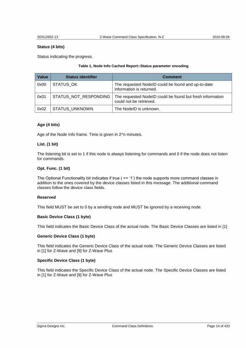
SDS12652-13 Z-Wave Command Class Specification, N-Z 2016-08-26
Sigma Designs Inc. Command Class Definitions Page 14 of 420
Status (4 bits)
Status indicating the progress.
Table 1, Node Info Cached Report::Status parameter encoding
Value Status identifier Comment
0x00 STATUS_OK The requested NodeID could be found and up-to-date information is returned.
0x01 STATUS_NOT_RESPONDING The requested NodeID could be found but fresh information could not be retrieved.
0x02 STATUS_UNKNOWN The NodeID is unknown.
Age (4 bits)
Age of the Node Info frame. Time is given in 2^n minutes.
List. (1 bit)
The listening bit is set to 1 if this node is always listening for commands and 0 if the node does not listen for commands.
Opt. Func. (1 bit)
The Optional Functionality bit indicates if true ( == ‘1’) the node supports more command classes in addition to the ones covered by the device classes listed in this message. The additional command classes follow the device class fields.
Reserved
This field MUST be set to 0 by a sending node and MUST be ignored by a receiving node.
Basic Device Class (1 byte)
This field indicates the Basic Device Class of the actual node. The Basic Device Classes are listed in [1]
Generic Device Class (1 byte)
This field indicates the Generic Device Class of the actual node. The Generic Device Classes are listed in [1] for Z-Wave and [9] for Z-Wave Plus
Specific Device Class (1 byte)
This field indicates the Specific Device Class of the actual node. The Specific Device Classes are listed in [1] for Z-Wave and [9] for Z-Wave Plus

SDS12652-13 Z-Wave Command Class Specification, N-Z 2016-08-26
Sigma Designs Inc. Command Class Definitions Page 15 of 420
Command Class (N bytes)
This field indicates the command classes implemented by the actual node.
The Command Class Support/Control Mark MUST be used to delimit Supported and Controlled Command Classes. The Support/Control Mark MUST be used before and after the Security Scheme 0 Mark.
The Security Scheme 0 Mark MUST be used to delimit Command Classes available non-securely and securely..
A Command Class field structure example is shown in Table 2. The field MUST comply with Table 3.
Table 2, Command Class field structure example
Description Command Class field content
7 6 5 4 3 2 1 0
Non-secure Supported Command Classes
Command Class 1 *)
…
Command Class M *)
Support/Control Mark 0xEF
Non-secure Controlled Command Classes
Command Class 1 *)
…
Command Class K *)
Security Scheme 0 Mark 0xF1
0x00
S0 Secure Supported Command Classes
Command Class 1 *)
…
Command Class L *)
Support/Control Mark 0xEF
S0 Secure Controlled Command Classes
Command Class 1 *)
…
Command Class P *)
*) Command classes may be extended spanning two bytes for one command class

SDS12652-13 Z-Wave Command Class Specification, N-Z 2016-08-26
Sigma Designs Inc. Command Class Definitions Page 16 of 420
Table 3, Special Command Class identifiers
Command Class ID Comment
0x20 .. 0xEE Command Class identifier
0xF101 .. 0xFFFF Extended Command Classes identifier
0xEF
Command Class Support/Control Mark
Anything between this mark and the next mark is Controlled and not supported
0xF100
Security Scheme 0 Command Class Mark.
Command Classes following this Mark are supported or controlled with Security Scheme 0

SDS12652-13 Z-Wave Command Class Specification, N-Z 2016-08-26
Sigma Designs Inc. Command Class Definitions Page 17 of 420
3.1.6 Network Management Basic Node Command Class, version 1
The Network Management Basic Node Command Class provides functions to get nodes included into a Z-Wave network, enabling nodes to request network updates and resetting itself factory default state.
3.1.6.1 Default Set Command
The Default Set Command sets the Controller back to the factory default state.
7 6 5 4 3 2 1 0
Command Class = COMMAND_CLASS_NETWORK_MANAGEMENT_BASIC
Command = COMMAND_DEFAULT_SET
Seq No
Warning: This function SHOULD be used with care as it could render a network unusable if the primary controller in an existing network is set back to default. If a node is set to default while it is still a member of a network, the node will become a failing nodeID in that network.
Seq No (1 byte)
This field MUST carry a unique sequence number as described in section 3.1.4.
3.1.6.2 Default Set Complete Command
The Default Set Complete Command Indicates that the Default Set Command execution has been completed.
7 6 5 4 3 2 1 0
Command Class = COMMAND_CLASS_NETWORK_MANAGEMENT_BASIC
Command = COMMAND_DEFAULT_SET_COMPLETE
Seq No
Status
Seq No (1 byte)
This field MUST carry a unique sequence number as described in section 3.1.4.
Status (1 byte)
Possible values are DEFAULT_SET_DONE or DEFAULT_SET_BUSY. A controller MUST return DEFAULT_SET_BUSY if it is already engaged in another network management command.

SDS12652-13 Z-Wave Command Class Specification, N-Z 2016-08-26
Sigma Designs Inc. Command Class Definitions Page 18 of 420
3.1.6.3 Learn Mode Set Command
The Learn Mode Set Command is used to allow a node to be added to (or removed from) the network. When a node is added to the network the node is assigned a valid Home ID and NodeID. This command allows a controlling application to request the transmission of Node Information frames in regular intervals until included or removed or until learn mode is disabled again.
NOTE: Learn mode SHOULD be enabled only when necessary, and it SHOULD always be disabled again as quickly as possible. However to ensure a successful synchronization of the inclusion process the device SHOULD be able to stay in learn mode in up to 5 seconds.
7 6 5 4 3 2 1 0
Command Class = COMMAND_CLASS_NETWORK_MANAGEMENT_BASIC
Command = COMMAND_LEARN_MODE_SET
Seq No
Reserved
Mode
Seq No (1 byte)
This field MUST carry a unique sequence number as described in section 3.1.4.
Reserved
This field MUST be set to 0 by a sending node and MUST be ignored by a receiving node.
Mode (1 byte)
The Mode field controls operation.
Table 4, Slave Learn Mode Set::Mode parameter encoding
Value Mode identifier Comment
0x01 ZW_SET_LEARN_MODE_CLASSIC Start the learn mode on the controller and accept only being included in direct range
0x02 ZW_SET_LEARN_MODE_NWI Start the learn mode on the controller and accept routed inclusion.
0x00 ZW_SET_LEARN_MODE_DISABLE Stop the learn mode of the node
3.1.6.3.1 Learn mode in a controller
If the node is a controller type the node receives and stores the node list and routing table for the network. The controller application receives and stores application information transmitted as part of the replication.
Note: This function will most likely change the capabilities of the controller.

SDS12652-13 Z-Wave Command Class Specification, N-Z 2016-08-26
Sigma Designs Inc. Command Class Definitions Page 19 of 420
3.1.6.4 Learn Mode Set Status Command
The Learn Mode Set Status Command is used to indicate the progress of the Learn Mode Set command.
7 6 5 4 3 2 1 0
Command Class = COMMAND_CLASS_NETWORK_MANAGEMENT_BASIC
Command = COMMAND_LEARN_MODE_SET_STATUS
Seq No
Status
Reserved
New NodeID
Seq No (1 byte)
This field MUST carry a unique sequence number as described in section 3.1.4.
Status (1 byte)
Status indicating the progress.
Table 5, Learn Mode Status::Status parameter encoding
Value Mode identifier Comment
0x06 LEARN_MODE_DONE The learn process is complete and the controller is now included into the network.
0x09 LEARN_MODE_SECURITY_FAILED The learn process is complete but security handshaking failed. The node is not operating securely.
0x07 LEARN_MODE_FAILED The learn process failed in some general way
The learn mode status message returns a LEARN_MODE_DONE if inclusion was completely successful. If a node supports security command classes, LEARN_MODE_DONE indicates that the inclusion was completed; including the security handshake. If inclusion is successful but security handshake fails, the status LEARN_MODE_SECURITY_FAILED MUST be returned.
Reserved
This field MUST be set to 0 by a sending node and MUST be ignored by a receiving node.
New NodeID (1 byte)
The NodeID assigned to the new node by another primary controller or inclusion controller. If the node was removed from the network, the new NodeID MUST be zero.

SDS12652-13 Z-Wave Command Class Specification, N-Z 2016-08-26
Sigma Designs Inc. Command Class Definitions Page 20 of 420
3.1.6.5 Node Information Send Command
When receiving this Node Information Send Command , a node MUST send out a Node Information Frame.
No status message is returned for this command.
A management application MAY use this message to make a NodeIDentify itself towards a classic Z-Wave remote control during association operations. This message SHOULD NOT be used while learn mode is activated. Instead, periodic Node Information transmissions MAY be enabled along with learn mode; refer to 3.1.6.1.
7 6 5 4 3 2 1 0
Command Class = COMMAND_CLASS_NETWORK_MANAGEMENT_BASIC
Command = COMMAND_NODE_INFORMATION_SEND
Seq No
Reserved
Destination NodeID
tx Options
Seq No (1 byte)
This field MUST carry a unique sequence number as described in section 3.1.4.
Reserved
This field MUST be set to 0 by a sending node and MUST be ignored by a receiving node.
Destination NodeID (1 byte)
The NodeID of the node that is to receive this Node Information frame. The NodeID MAY be set to the value NODE_BROADCAST to reach all nodes within direct range. Acknowledgement SHOULD NOT be requested when broadcasting.
tx Options (1 byte)
The tx Options field allows a management application to specify if the Node Information frame is to be sent with special properties. Several flags MAY be combined.

SDS12652-13 Z-Wave Command Class Specification, N-Z 2016-08-26
Sigma Designs Inc. Command Class Definitions Page 21 of 420
Table 6, Node Information Send::Tx Options encoding
Value Option flag identifier Comment
0x00 NULL Transmit at normal power level without any transmit options.
0x01 TRANSMIT_OPTION_ACK Request acknowledgment from destination node. Allow routing.
0x10 TRANSMIT_OPTION_NO_ROUTE Send only in direct range
0x20 TRANSMIT_OPTION_EXPLORE Resolve new routes via explorer discovery if existing routes fail
0x02 TRANSMIT_OPTION_LOW_POWER Transmit at low output power level (1/3 of normal RF range)
The typical tx option flags used for Node Information Send will be TRANSMIT_OPTION_NO_ROUTE and the nodeID will be the broadcast NodeID.
3.1.6.6 Network Update Request Command
The Network Update Request Command is used to request network topology updates from the SUC/SIS node. All controllers can use this call in case a SUC ID Server (SIS) is available. Secondary controllers can only use this call when a SUC is present in the network. Routing Slaves can only use this call, when a SUC is present in the network.
7 6 5 4 3 2 1 0
Command Class = COMMAND_CLASS_NETWORK_MANAGEMENT_BASIC
Command = COMMAND_NETWORK_UPDATE_REQUEST
Seq No
NOTE: The SUC can only handle one network update at a time, so care should be taken not to have multiple controllers in the network ask for updates at the same time. WARNING: This API call will generate a lot of network activity that will use bandwidth and stress the SUC in the network. Therefore, network updates SHOULD be requested as seldom as possible.
Seq No (1 byte)
This field MUST carry a unique sequence number as described in section 3.1.4.

SDS12652-13 Z-Wave Command Class Specification, N-Z 2016-08-26
Sigma Designs Inc. Command Class Definitions Page 22 of 420
3.1.6.7 Network Update Request Status Command
The Network Update Request Status Command indicates that the Network Update Request command execution has completed.
7 6 5 4 3 2 1 0
Command Class = COMMAND_CLASS_NETWORK_MANAGEMENT_BASIC
Command = COMMAND_NETWORK_UPDATE_REQUEST_STATUS
Seq No
Status
Seq No (1 byte)
This field MUST carry a unique sequence number as described in section 3.1.4.
Status (1 byte)
Indicates the status of the Network Update process.
Table 7, Network Update Request Status::Status parameter encoding
Value Status identifier Comment
0x00 ZW_SUC_UPDATE_DONE The update process succeeded
0x01 ZW_SUC_UPDATE_ABORT The update process aborted because of an error
0x02 ZW_SUC_UPDATE_WAIT The SUC node is busy
0x03 ZW_SUC_UPDATE_DISABLED The SUC functionality is disabled
0x04 ZW_SUC_UPDATE_OVERFLOW The controller requested an update after more than 64 changes have occurred in the network. The controller has to make a replication.

SDS12652-13 Z-Wave Command Class Specification, N-Z 2016-08-26
Sigma Designs Inc. Command Class Definitions Page 23 of 420
3.1.7 Network Management Inclusion Command Class, version 1
The Network Management Inclusion Command Class provides functionality only available in a primary controller. Since this is a dynamic property, there is a risk that a remote host tries to use commands in a controller which has become secondary in the meantime.
If a requesting node tries to use a command which is not supported in the current configuration the node MUST return a “Command Class Not Supported” as defined per the Application Capability Command class.
3.1.7.1 Node Add Command
The Node Add Command is used to add nodes to the network.
The process of adding a node is started by the network management application sending a Node Add command to the Node List Controller (primary controller). The network management application receives a status message indicating if inclusion was successful. If NWI inclusion was used, the calling application MAY re-issue the Node Add command if more nodes are to be included.
7 6 5 4 3 2 1 0
Command Class = COMMAND_CLASS_NETWORK_MANAGEMENT_INCLUSION
Command = COMMAND_NODE_ADD
Seq No
Reserved
Mode
tx Options
Seq No (1 byte)
This field MUST carry a unique sequence number as described in section 3.1.4.
NOTE: The Node Add state SHOULD be disabled after use to avoid adding other nodes than expected. It is RECOMMENDED to have a timer that disables the Node Add state after a while without any activity.
Reserved
This field MUST be set to 0 by a sending node and MUST be ignored by a receiving node.
Mode (1 byte)
Table 8, Node Add::Mode parameter encoding
Value Mode identifier Comment
0x01 ADD_NODE_ANY Add any type of node to the network.
0x05 ADD_NODE_STOP Stop adding nodes to the network. A call with this mode will always result in a status message reporting ADD_NODE_STATUS_FAILED

SDS12652-13 Z-Wave Command Class Specification, N-Z 2016-08-26
Sigma Designs Inc. Command Class Definitions Page 24 of 420
tx Options (1 byte)
The tx Options field allows a controlling node to specify if transmissions MUST use special properties. Several flags MAY be combined.
Table 9, Node Add::Tx Options encoding
Value Option flag identifier Comment
0x00 NULL Transmit at normal power level without any transmit options.
0x20 TRANSMIT_OPTION_EXPLORE Allow network-wide inclusion
0x02 TRANSMIT_OPTION_LOW_POWER Transmit at low output power level (1/3 of normal RF range)
The RECOMMENDED use of option flags in combination with the NODE_ADD_ANY option is to set the flag TRANSMIT_OPTION_EXPLORE. Installer scenarios with a requirement for more confidential transfer of network security keys MAY set the flag TRANSMIT_OPTION_LOW_POWER. This requires that a new node is included in direct range of the primary controller.

SDS12652-13 Z-Wave Command Class Specification, N-Z 2016-08-26
Sigma Designs Inc. Command Class Definitions Page 25 of 420
3.1.7.2 Node Add Status Command
The Node Add Status Command is used to report the result of the Node Add command.
To avoid re-entrance issues and transmit queue overflows, the Node Add Status message SHOULD be issued before or after processing the Node Add message but never during the execution of the function.
7 6 5 4 3 2 1 0
Command Class = COMMAND_CLASS_NETWORK_MANAGEMENT_INCLUSION
Command = COMMAND_NODE_ADD_STATUS
Seq No
Status
Reserved
New NodeID
Node Info Length
List. Capability
Opt. Func.
Security
Basic Device Class
Generic Device Class
Specific Device Class
Command Class 1 *)
...
Command Class N *)
*) Command classes may be extended spanning two bytes for one command class
Seq No (1 byte)
This field MUST carry a unique sequence number as described in section 3.1.4.
Status (1 byte)
Indicates the status of the Node Add process.
Table 10, Node Add Status::Status parameter encoding
Value Status identifier Comment
0x06 ADD_NODE_STATUS_DONE The new node has now been included.
0x07 ADD_NODE_STATUS_FAILED The process failed
0x09 ADD_NODE_STATUS_SECURITY_FAILED Node has been included but the secure inclusion failed.

SDS12652-13 Z-Wave Command Class Specification, N-Z 2016-08-26
Sigma Designs Inc. Command Class Definitions Page 26 of 420
The Node Add status message returns a NODE_ADD_STATUS_DONE if inclusion was completely successful. If a node supports security command classes, NODE_ADD_STATUS_DONE indicates that the inclusion was completed; including the security handshake. If inclusion is successful but security handshake fails, the status NODE_ADD_STATUS_SECURITY_FAILED MUST be returned.
Reserved
This field MUST be set to 0 by a sending node and MUST be ignored by a receiving node.
New NodeID (1 byte)
The NodeID of the newly added node. Only valid if Status is NODE_ADD_STATUS_DONE; else this field MUST be zero.
Node Info Length (1 byte)
The length of the encapsulated Node Information. The length value includes the length field.
Node Info (N bytes)
The node info structure of the newly added node. The length is signaled in Node Info Length.
Basic Device Class (1 byte)
See description in 3.1.5.4 Node Info Cached Report Command.
Generic Device Class (1 byte)
See description in 3.1.5.4 Node Info Cached Report Command.
Specific Device Class (1 byte)
See description in 3.1.5.4 Node Info Cached Report Command.
Command Class (N bytes)
See description in 3.1.5.4 Node Info Cached Report Command and in Table 3.

SDS12652-13 Z-Wave Command Class Specification, N-Z 2016-08-26
Sigma Designs Inc. Command Class Definitions Page 27 of 420
3.1.7.3 Node Remove Command
The Node Remove Command is used to remove any node from the network. The remove operation only works in direct range between the controller and the node that is to be deleted.
7 6 5 4 3 2 1 0
Command Class = COMMAND_CLASS_NETWORK_MANAGEMENT_INCLUSION
Command = COMMAND_NODE_REMOVE
Seq No
Reserved
Mode
There is no NodeID in this message. The NodeID of the node SHOULD be received from the actual node since the NodeID must be cleared in the deleted node as well as in the primary controller.
NOTE: The Node Remove state SHOULD be disabled after use to avoid adding other nodes than expected. It is RECOMMENDED that Node Remove is sent with NODE_REMOVE_STOP every time a NODE_REMOVE_STATUS_DONE is received, and that the controller also contains a timer that disables the Node Remove state.
Seq No (1 byte)
This field MUST carry a unique sequence number as described in section 3.1.4.
Reserved
This field MUST be set to 0 by a sending node and MUST be ignored by a receiving node.
Mode (1 byte)
Table 11, Node Remove::Mode parameter encoding
Value Mode identifier Comment
0x01 REMOVE_NODE_ANY Remove any type of node from the network
0x05 REMOVE_NODE_STOP Stop the delete process
The process of removing a node is started by sending Node Remove. The delete process is complete when the status NODE_REMOVE_STATUS_DONE is returned.
3.1.7.4 Node Remove Status Command
The Node Remove Status Command is used to report progress during the removal of nodes.
To avoid re-entrance issues and tx queue overflows, the Node RemoveStatus message SHOULD be emitted before and after calling the API function RemoveNodeFromNetwork but never during the execution of the API function.

SDS12652-13 Z-Wave Command Class Specification, N-Z 2016-08-26
Sigma Designs Inc. Command Class Definitions Page 28 of 420
7 6 5 4 3 2 1 0
Command Class = COMMAND_CLASS_NETWORK_MANAGEMENT_INCLUSION
Command = COMMAND_NODE_REMOVE_STATUS
Seq No
Status
NodeID
Seq No (1 byte)
This field MUST carry a unique sequence number as described in section 3.1.4.
Status (1 byte)
Indicates the status of the node remove process.
Table 12, Status parameter of Node Remove Status encoding
Value Status identifier Comment
0x06 REMOVE_NODE_STATUS_DONE The node has now been removed and the controller is ready to continue normal operation again. Removed NodeID is returned.
0x07 REMOVE_NODE_STATUS_FAILED The remove process failed
NodeID (1 byte)
MUST be the NodeID that was attempted to be removed.
3.1.7.5 Failed Node Remove Command
The Failed Node Remove Command is used to remove a non-responding node. A non-responding node is put onto the failed NodeID list in the controller. In case the node responds again at a later stage then it is removed from the failed NodeID list. A node MUST be on the failed NodeID list and as an extra precaution also fail to respond before it is removed. Responding nodes MUST NOT be removed.
7 6 5 4 3 2 1 0
Command Class = COMMAND_CLASS_NETWORK_MANAGEMENT_INCLUSION
Command = COMMAND_FAILED_NODE_REMOVE
Seq No
NodeID
Seq No (1 byte)
This field MUST carry a unique sequence number as described in section 3.1.4.

SDS12652-13 Z-Wave Command Class Specification, N-Z 2016-08-26
Sigma Designs Inc. Command Class Definitions Page 29 of 420
NodeID (1 byte)
NodeID to be removed.

SDS12652-13 Z-Wave Command Class Specification, N-Z 2016-08-26
Sigma Designs Inc. Command Class Definitions Page 30 of 420
3.1.7.6 Failed Node Remove Status Command
The Failed Node Remove Status Command is used to indicate the progress of the Remove Failed Node Command.
7 6 5 4 3 2 1 0
Command Class = COMMAND_CLASS_NETWORK_MANAGEMENT_INCLUSION
Command = COMMAND_FAILED_NODE_REMOVE_STATUS
Seq No
Status
NodeID
Seq No (1 byte)
This field MUST carry a unique sequence number as described in section 3.1.4.
Status (1 byte)
Status field indicating the result of the operation.
Table 13, Status parameter of Failed NodeID Remove::Status encoding
Value Status identifier Comment
0x01 DONE The process was completed successfully.
0x00 FAILED_NODE_NOT_FOUND The requested process failed. The NodeID was not found in the controller list of failing nodes.
0x02 FAILED_NODE_REMOVE_FAIL The requested process failed. Reasons include: * Controller is busy * The node responded to a NOP; thus the node is no longer failing.
The removal process may fail if the requested NodeID responds to requests. The error message FAILED_NODE_REMOVE_FAIL does not indicate why the removal operation failed. A network management application SHOULD issue a NOP for the requested NodeID to test if the node is actually responding again.
NodeID (1 byte)
NodeID that was to be removed.

SDS12652-13 Z-Wave Command Class Specification, N-Z 2016-08-26
Sigma Designs Inc. Command Class Definitions Page 31 of 420
3.1.7.7 Failed Node Replace Command
The Failed Node Replace Command is used to replace a non-responding node with a new one in having the same NodeID. A non-responding node is put onto the failed NodeID list in the controller. In case the node responds again at a later stage then it is removed from the failed NodeID list. A node MUST be on the failed NodeID list and as an extra precaution also fail to respond before it is removed or replaced. Responding nodes cannot be removed.
7 6 5 4 3 2 1 0
Command Class = COMMAND_CLASS_NETWORK_MANAGEMENT_INCLUSION
Command = COMMAND_FAILED_NODE_REPLACE
Seq No
NodeID
tx Options
Mode
Seq No (1 byte)
This field MUST carry a unique sequence number as described in section 3.1.4.
NodeID (1 byte)
NodeID to be replaced.
tx Options (1 byte)
The tx Options field allows a controlling node to specify if transmissions must use special properties.
Table 14, Failed Node Replace::Tx Options encoding
Value Option flags Comment
0x00 NULL Transmit at normal power level without any transmit options.
0x02 TRANSMIT_OPTION_LOW_POWER Transmit at low output power level (1/3 of normal RF range)
::
Mode (1 byte)
Mode field indicating type of operation.
Table 15, Failed Node Replace::Mode encoding
Value Mode identifier Comment
0x01 START_FAILED_NODE_REPLACE Initiate a failed node replace process.
0x05 STOP_FAILED_NODE_REPLACE Cancel a failed node replace process.

SDS12652-13 Z-Wave Command Class Specification, N-Z 2016-08-26
Sigma Designs Inc. Command Class Definitions Page 32 of 420
3.1.7.8 Failed Node Replace Status Command
The Failed Node Replace Status Command is used to indicate the progress of the Replace Failed Node Command.
7 6 5 4 3 2 1 0
Command Class = COMMAND_CLASS_NETWORK_MANAGEMENT_INCLUSION
Command = COMMAND_FAILED_NODE_REPLACE_STATUS
Seq No
Status
NodeID
Seq No (1 byte)
This field MUST carry a unique sequence number as described in section 3.1.4.
Status (1 byte)
Status field indicating the result of the operation.
Table 16, Status parameter of Failed Node Remove ID::Status encoding
Value Status identifier Comment
0x04 DONE The process was completed successfully.
0x05 FAILED_NODE_REPLACE_FAIL The requested process failed. Reasons include: * Controller is busy * The node responded to a NOP; thus the node is no longer failing.
0x09 FAILED_NODE_REPLACE_SECURITY_FAILED Replace completed successfully but security handshake failed.
The replace process may fail if the requested NodeID responds to requests. The error message FAILED_NODE_REMOVE_FAIL does not indicate why the removal operation failed.
A network management application SHOULD issue a NOP for the requested NodeID. If a response is received the user SHOULD be notified that the node must be removed using the normal removal operation.
NodeID (1 byte)
NodeID that was to be replaced.

SDS12652-13 Z-Wave Command Class Specification, N-Z 2016-08-26
Sigma Designs Inc. Command Class Definitions Page 33 of 420
3.1.7.9 Node Neighbor Update Request Command
The Node Neighbor Update Request Command is used to instruct a node with NodeID to perform a Node Neighbor Search, to update the topology on the controller.
7 6 5 4 3 2 1 0
Command Class = COMMAND_CLASS_NETWORK_MANAGEMENT_INCLUSION
Command = COMMAND_NODE_NEIGHBOR_UPDATE_REQUEST
Seq No
NodeID
Seq No (1 byte)
This field MUST carry a unique sequence number as described in section 3.1.4.
NodeID (1 byte)
NodeID of the node that should perform Node Neighbor search.
3.1.7.10 Node Neighbor Update Status Command
The Node Neighbor Update Status Command Status of the Request Node Neighbor Update Command.
7 6 5 4 3 2 1 0
Command Class = COMMAND_CLASS_NETWORK_MANAGEMENT_INCLUSION
Command = COMMAND_NODE_NEIGHBOR_UPDATE_STATUS
Seq No
Status
Seq No (1 byte)
This field MUST carry a unique sequence number as described in section 3.1.4.
Status (1 byte)
Status field indicating the result of the operation.
Table 17, Node Neighbor Update Status::Status encoding
Value Status identifier Comment
0x22 NEIGHBOR_UPDATE_STATUS_DONE New neighbor list received
0x23 NEIGHBOR_UPDATE_STATUS_FAIL Getting new neighbor list failed

SDS12652-13 Z-Wave Command Class Specification, N-Z 2016-08-26
Sigma Designs Inc. Command Class Definitions Page 34 of 420
3.1.7.11 Return Route Assign Command
An application may call the Return Route Assign Command to make a controller assign static return routes (up to 4) to a Routing Slave node or Enhanced Slave node. This allows the Routing Slave node to communicate directly with either controllers or other slave nodes.
Up to 5 different destinations can be allocated return routes. Attempts to assign new return routes when all 5 destinations already are allocated will be ignored. Allocated return routes can only be cleared by the call Return Route Delete.
7 6 5 4 3 2 1 0
Command Class = COMMAND_CLASS_NETWORK_MANAGEMENT_INCLUSION
Command = COMMAND_RETURN_ROUTE_ASSIGN
Seq No
Source NodeID
Destination NodeID
Seq No (1 byte)
This field MUST carry a unique sequence number as described in section 3.1.4.
Source NodeID (1 byte)
The controller calculates the shortest routes from the Routing Slave node (Source NodeID) to the destination node (Destination NodeID) and transmits the return routes to the Routing Slave node (Source NodeID).
Destination NodeID (1 byte)
Refer to Source NodeID.
3.1.7.12 Return Route Assign Complete Command
The Return Route Assign Complete Command indicates status of the Return Route Assign Command. The call indicates that the function completed without errors in the communication. The call may have been ignored if there was no capacity left in the Destination Node for more return routes. Refer to Return Route Delete for details on how to re-gain route capacity.
7 6 5 4 3 2 1 0
Command Class = COMMAND_CLASS_NETWORK_MANAGEMENT_INCLUSION
Command = COMMAND_RETURN_ROUTE_ASSIGN_COMPLETE
Seq No
Status

SDS12652-13 Z-Wave Command Class Specification, N-Z 2016-08-26
Sigma Designs Inc. Command Class Definitions Page 35 of 420
Seq No (1 byte)
This field MUST carry a unique sequence number as described in section 3.1.4.
Status (1 byte)
Status field refers to the transmission status of the command.
Table 18, Return Route Assign Complete::Status encoding
Value Option identifier Comment
0x00 TRANSMIT_COMPLETE_OK Successfully transmitted
0x01 TRANSMIT_COMPLETE_NO_ACK No acknowledge is received before timeout from the destination node. Acknowledge is discarded in case it is received after the time out.
0x02 TRANSMIT_COMPLETE_FAIL Not possible to transmit data because the Z-Wave network is busy (jammed).
3.1.7.13 Return Route Delete Command
An application may call the Return Route Delete Command to make a controller delete all static return routes from a Routing Slave node or Enhanced Slave node. Allocated return routes can only be cleared by the call Return Route Delete. All return routes are cleared by this call.
After issuing the Return Route Delete command, an application SHOULD issue Return Route Assign commands repeatedly to create return routes for all relevant associations.
7 6 5 4 3 2 1 0
Command Class = COMMAND_CLASS_NETWORK_MANAGEMENT_INCLUSION
Command = COMMAND_RETURN_ROUTE_DELETE
Seq No
NodeID
Seq No (1 byte)
This field MUST carry a unique sequence number as described in section 3.1.4.

SDS12652-13 Z-Wave Command Class Specification, N-Z 2016-08-26
Sigma Designs Inc. Command Class Definitions Page 36 of 420
NodeID (1 byte)
The call deletes all return routes in the routing slave identified by the NodeID.
3.1.7.14 Return Route Delete Complete Command
The Return Route Delete Complete Command indicates status of the Return Route Delete Command.
7 6 5 4 3 2 1 0
Command Class = COMMAND_CLASS_NETWORK_MANAGEMENT_INCLUSION
Command = COMMAND_RETURN_ROUTE_DELETE_COMPLETE
Seq No
Status
Seq No (1 byte)
This field MUST carry a unique sequence number as described in section 3.1.4.
Status (1 byte)
Status field refers to the transmission status of the command.
Table 19, Return Route Delete Complete::Status encoding
Value Option identifier Comment
0x00 TRANSMIT_COMPLETE_OK Successfully transmitted
0x01 TRANSMIT_COMPLETE_NO_ACK No acknowledge is received before timeout from the destination node. Acknowledge is discarded in case it is received after the time out.
0x02 TRANSMIT_COMPLETE_FAIL Not possible to transmit data because the Z-Wave network is busy (jammed).

SDS12652-13 Z-Wave Command Class Specification, N-Z 2016-08-26
Sigma Designs Inc. Command Class Definitions Page 37 of 420
3.1.8 Network Management Primary Command Class, version 1
The Network Management Primary Command Class provides functions to pass on the primary role to another controller.
3.1.8.1 Controller Change Command
The Controller Change Command is used to add a controller node to the network and make the new controller primary.
This function has the same functionality as Node Add with the exception that the new controller will be a primary controller and the controller invoking the function will become secondary.
7 6 5 4 3 2 1 0
Command Class = COMMAND_CLASS_NETWORK_MANAGEMENT_PRIMARY
Command = COMMAND_CONTROLLER_CHANGE
Seq No
Reserved
Mode
tx Options
Seq No (1 byte)
This field MUST carry a unique sequence number as described in section 3.1.4.
Reserved
This field MUST be set to 0 by a sending node and MUST be ignored by a receiving node.
Mode (1 byte)
Table 20, Controller Change::Mode parameter encoding
Value Mode identifier Comment
0x02 CONTROLLER_CHANGE_START Start the process of creating a new primary controller for the network
0x05 CONTROLLER_CHANGE_STOP Stop the controller change and report a failure
The process of adding a new controller node and transferring control to the new controller node is started by the application sending a Controller Change command. The application receives a status message indicating if the process was successful.
tx Options (1 byte)
The tx Options field allows a controlling node to specify if transmissions MUST use special properties. Several flags MAY be combined.

SDS12652-13 Z-Wave Command Class Specification, N-Z 2016-08-26
Sigma Designs Inc. Command Class Definitions Page 38 of 420
Table 21, Controller Change::Tx Options encoding
Value Option identifier Comment
0x00 NULL Transmit at normal power level without any transmit options.
0x20 TRANSMIT_OPTION_EXPLORE Resolve new routes via explorer discovery if existing routes fail
0x02 TRANSMIT_OPTION_LOW_POWER Transmit at low output power level (1/3 of normal RF range)
3.1.8.2 Controller Change Status Command
The Controller Change Status Command is used to report the result of the Controller Change Command.
To avoid re-entrance issues and transmit queue overflows, the Controller Change Status message SHOULD be issued before or after processing the Controller Change message but never during the execution of the function.
7 6 5 4 3 2 1 0
Command Class = COMMAND_CLASS_NETWORK_MANAGEMENT_PRIMARY
Command = COMMAND_CONTROLLER_CHANGE_STATUS
Seq No
Status
Reserved
New NodeID
Node Info Length
List. Capability
Opt. Func.
Security
Basic Device Class
Generic Device Class
Specific Device Class
Command Class 1 *)
...
Command Class N *)
*) Command classes may be extended spanning two bytes for one command class
Seq No (1 byte)
This field MUST carry a unique sequence number as described in section 3.1.4.

SDS12652-13 Z-Wave Command Class Specification, N-Z 2016-08-26
Sigma Designs Inc. Command Class Definitions Page 39 of 420
Status (1 byte)
Indicates the status of the Controller Change process. The constant labels defined for the Node Add command are reused for the Controller Change Status message.
Table 22, Controller Change Status::Status parameter encoding
Value Status identifier Comment
0x06 ADD_NODE_STATUS_DONE The new node has now been included.
0x07 ADD_NODE_STATUS_FAILED The process failed
0x09 ADD_NODE_STATUS_SECURITY_FAILED Node has been included but the secure inclusion failed.
Reserved
This field MUST be set to 0 by a sending node and MUST be ignored by a receiving node.
New NodeID (1 byte)
The NodeID of the newly added node. Only valid if Status is NODE_ADD_STATUS_DONE; else this field MUST be zero.
Node Info Length (1 byte)
The length of the encapsulated Node Information. The length value includes the length field.
If status is NODE_ADD_STATUS_DONE, the Node Information fields carry valid information. Else this field MUST be ignored.
Node Info (N bytes)
The node info structure of the newly added node. The length is signaled in Node Info Length.
If status is NODE_ADD_STATUS_DONE, the Node Information fields carry valid information. Else this field MUST be ignored.
Basic Device Class (1 byte)
See description in 3.1.5.4 Node Info Cached Report Command.
Generic Device Class (1 byte)
See description in 3.1.5.4 Node Info Cached Report Command.
Specific Device Class (1 byte)

SDS12652-13 Z-Wave Command Class Specification, N-Z 2016-08-26
Sigma Designs Inc. Command Class Definitions Page 40 of 420
See description in 3.1.5.4 Node Info Cached Report Command.
Command Class (N bytes)
See description in 3.1.5.4 Node Info Cached Report Command and in Table 3.
3.1.9 Network Management Installation and Maintenance Command Class, Version 1
The Network Management Installation and Maintenance Command Class is used to access statistical data. Data relating to the transmission of an actual frame may be obtained via the Z/IP Packet Installation and Maintenance Header Extension.
All Transmissions / Route Information: o Packet Error Count (PEC) – Also sometimes referred to as PER.
The number of unsuccessful transmissions experienced by the device. o Transmission Counter (TC) – Number of frames sent by the specified device. o Neighbors (NB) – Information on known neighbors for a specified device. o Network Management - Last Working Route Set o Network Management - Last Working Route Get o Network Management - Last Working Route Report
3.1.9.1 Last Working Route Set
The Last Working Route Set Command MAY be used to set the Last Working Route to use when sending commands to the specified NodeID.
The use of this command is NOT RECOMMENDED.
7 6 5 4 3 2 1 0
COMMAND_CLASS = NETWORK_MANAGEMENT_INSTALLATION_MAINTENANCE
COMMAND = LAST_WORKING_ROUTE_SET
NodeID
Repeater 1 [First repeater]
Repeater 2
Repeater 3
Repeater 4 [Last repeater]
Speed.
NodeID (1 byte)
The NodeID specifies the destination node for which a LWR is to be set.
Repeater (1 byte)
Repeater 1 - 4 contains the NodeIDs used for the route. The value 0 MUST indicate that this byte does not represent a repeater. If the route is shorter than four repeaters, Repeater 1 MUST contain the first repeater NodeID. If Repeater 1 is zero then the LWR is direct.

SDS12652-13 Z-Wave Command Class Specification, N-Z 2016-08-26
Sigma Designs Inc. Command Class Definitions Page 41 of 420
Speed (1 byte)
Table 23, IME Speed Encoding
Value Speed
0x01 9.6 kbit/sec
0x02 40 kbit/sec
0x03 100 kbit/sec
3.1.9.2 Last Working Routes Get
The Last Working Routes Get Command is used to query the Last Working Route from a node.
The Last Working Routes Report Command MUST be returned in response to this command.
This command MUST NOT be issued via multicast addressing. A receiving node MUST NOT return a response if this command is received via multicast addressing. The Z-Wave Multicast frame, the broadcast NodeID and the Multi Channel multi-End Point destination are all considered multicast addressing methods.
7 6 5 4 3 2 1 0
COMMAND_CLASS = NETWORK_MANAGEMENT_INSTALLATION_MAINTENANCE
COMMAND = LAST_WORKING_ROUTES_GET
NodeID
NodeID (1 byte)
The NodeID specifies the destination node for which a LWR is requested.

SDS12652-13 Z-Wave Command Class Specification, N-Z 2016-08-26
Sigma Designs Inc. Command Class Definitions Page 42 of 420
3.1.9.3 Last Working Routes Report
The Last Working Routes Report contains the 1 or more Last Working Routes available for the given NodeID.
The order of the data blocks MUST reflect the priority of the routes; the first being the highest priority.
7 6 5 4 3 2 1 0
COMMAND_CLASS = NETWORK_MANAGEMENT_INSTALLATION_MAINTENANCE
COMMAND = LAST_WORKING_ROUTES_REPORT
NodeID.
Type – 1.
Repeater 1 – 1 [First repeater]
Repeater 2 – 1.
Repeater 3 – 1.
Repeater 4 – 1 [Last repeater]
Speed -1.
…
Type – N.
Repeater 1 – N [First repeater]
Repeater 2 – N.
Repeater 3 – N.
Repeater 4 – N [Last repeater]
Speed – N.
Type (1 byte)
Table 24, Route type encoding
Type Description
Static The Route is not overwritten by the protocol and will only change in response to the Last Working Route Set command
Dynamic The Route is determined by the protocol and may change over time
Repeater n (1 byte)
Refer to the Last Working Route Set Command.
Speed (1 byte)
Refer to the Last Working Route Set Command.

SDS12652-13 Z-Wave Command Class Specification, N-Z 2016-08-26
Sigma Designs Inc. Command Class Definitions Page 43 of 420
3.1.9.4 Statistics Get
The Statistics Get Command is used to query Installation and Maintenance statistics from a node.
The Statistics Report Command MUST be returned in response to this command.
This command MUST NOT be issued via multicast addressing. A receiving node MUST NOT return a response if this command is received via multicast addressing. The Z-Wave Multicast frame, the broadcast NodeID and the Multi Channel multi-End Point destination are all considered multicast addressing methods.
7 6 5 4 3 2 1 0
COMMAND_CLASS = NETWORK_MANAGEMENT_INSTALLATION_MAINTENANCE
COMMAND = STATISTICS_GET
NodeID
NodeID (1 byte)
The NodeID specifies the node for which statistics are requested.
3.1.9.5 Statistics Report
7 6 5 4 3 2 1 0
COMMAND_CLASS = NETWORK_MANAGEMENT_INSTALLATION_MAINTENANCE
COMMAND = STATISTICS_REPORT
NodeID
Statistics – Type 1
Statistics – Length 1
Statistics – Value 1
…
Statistics – Type N
Statistics – Length N
Statistics – Value N
NodeID (1 byte)
The NodeId field MUST carry the same value as received in the Statistics Get Command.
Statistics (N bytes)
The statistics field MUST be formatted as cascaded Type-Length-Value (TLV) structures.
The Z/IP Gateway MAY send any combination of TLV structures.

SDS12652-13 Z-Wave Command Class Specification, N-Z 2016-08-26
Sigma Designs Inc. Command Class Definitions Page 44 of 420
Table 25, Statistics Get::Type encoding
Name Statistics – Type Statistics - Length (Bytes)
Route Changes (RC) 0 1
Transmission Count (TC) 1 1
Neighbors (NB) 2 n
Packet Error Count (PEC) 3 1
Sum of transmission times (TS) 4 4
Sum of transmission times squrared (TS2)
5 4
All other values are reserved and MUST NOT be used by a sending node. Reserved values MUST be ignored by a receiving node.
3.1.9.5.1 Route Changes (RC)
7 6 5 4 3 2 1 0
Statistics - Type = 0x00
Statistics – Length = 1
Statistics – Value = Route Changes
Route Changes (1 byte)
The RC field is used to advertise the number of routing attempts needed to reach a destination. The number is a combination of Last Working Route (LWR) changes and Jitter measurements during transmission attempts between the Z/IP Gateway and the Z-Wave device.
RC is incremented automatically by the Z/IP Gateway when either of the below conditions are true:
Last Working Route changed from the transmission of one command to the next
Tn – Tn-1 > 150ms where Tn and Tn-1 = the time needed to complete a transmission of a command o IF 2 channel and FLIRS node, RC: Tn = Tn mod 1100 o IF 3 channel and FLIRS node, RC cannot increment based on time calculation
3.1.9.5.2 Transmission Count (TC)
7 6 5 4 3 2 1 0
Statistics - Type = 0x01
Statistics – Length = 1
Statistics – Value = Transmission Count
Transmission Count (1 byte)
Total number of transmissions sent by all Z/IP Clients through the Z/IP GW to the specified Z-Wave destination node.

SDS12652-13 Z-Wave Command Class Specification, N-Z 2016-08-26
Sigma Designs Inc. Command Class Definitions Page 45 of 420
3.1.9.5.3 Neighbors (NB)
7 6 5 4 3 2 1 0
Statistics - Type = 0x02
Statistics – Length = N * 2
Statistics – Value = NodeID 1
Statistics – Value = Repeater
1
Reserved Statistics – Value = Speed 1
…
Statistics – Value = NodeID N
Statistics – Value = Repeater
N
Reserved Statistics – Value = Speed N
NodeID (N * 1 byte)
The NodeID of the actual neighbor.
Speed (N * 4 bits)
Table 26, Statistics Report::Speed Encoding
Bitmask Speed
0x01 9.6 kbit/sec
0x02 40 kbit/sec
0x04 100 kbit/sec
All other values are reserved and MUST NOT be used by a sending node. Reserved values MUST be ignored by a receiving node.
Repeater (N * 1 bit)
If this bit is set then the node is a repeater.
3.1.9.5.4 Packet Error Count (PEC)
7 6 5 4 3 2 1 0
Statistics - Type = 0x03
Statistics – Length = 1
Statistics – Value = Packet Error Count

SDS12652-13 Z-Wave Command Class Specification, N-Z 2016-08-26
Sigma Designs Inc. Command Class Definitions Page 46 of 420
Packet Error Count (1 byte)
Also sometimes referred to as PER. PEC is measured by the Gateway. The PEC value MUST be incremented each time the Gateway detects a failing transmission for each specific Z-Wave destination node.
Sum of transmission times (4 bytes)
The sum of all transmission times. This may be used to calculate the average transmission time. The time is given as a 32-bit unsigned integer MSB in milliseconds.
Where N is the number of transmissions.
Sum of transmission times squared (4 bytes)
The sum of the square of all transmission times. This may be used to calculate the variance of the transmission time. The time is given as a 32bit unsigned integer MSB in milliseconds^2.
The Variance may be calculated as follows:
(König-Huygens theorem)
Where N is the number of transmissions.
A high variance is a sign of a bad link.
3.1.9.6 Statistics Clear
The Statistics Clear Command is used to clear all statistic registers maintained by the node.
7 6 5 4 3 2 1 0
COMMAND_CLASS = NETWORK_MANAGEMENT_INSTALLATION_MAINTENANCE
COMMAND = STATISTICS_CLEAR
A receiving node MUST set all counters to 0.

SDS12652-13 Z-Wave Command Class Specification, N-Z 2016-08-26
Sigma Designs Inc. Command Class Definitions Page 47 of 420
3.1.10 Use Cases
3.1.10.1 Intranode network management: TV OSD System controlling lamps
Intranode network management is the process closest to classic Z-Wave API programming. No messages ever leave the device. Messages only flow between different software modules.
TV set
Use Case: TV OSD System (island mode)
TV UserTV User
Add NodeAdd Node
<<system>>
TV OSD Application
<<system>>
TV OSD Application
Delete NodeDelete Node
ResetReset
Z-Wave commands
in UDP packets
<<actor>>
New node
<<actor>>
New node
<<actor>>
Existing node
<<actor>>
Existing node
Figure 2, TV OSD System controlling lamps
Using UDP/IP for carrying the messages allows for a simple integration interface between applications designed by different partners.

SDS12652-13 Z-Wave Command Class Specification, N-Z 2016-08-26
Sigma Designs Inc. Command Class Definitions Page 48 of 420
3.1.10.2 Intranet network management: Remote controlling a primary controller
Intranet network management extends the use of command messages to separate physical devices. Messages flow between software modules but the modules reside in separate physical entities having individual IP addresses – or at least separate NodeIDs.
Primary controller
Use Case: Managing a primary static controller from a remote control
Home UserHome User
Add NodeAdd Node
<<system>>
Management device
<<system>>
Management device
Delete NodeDelete Node
ResetReset
Z-Wave commands
OR
Z-Wave commands
in UDP packets
<<actor>>
New node
<<actor>>
New node
<<actor>>
Existing node
<<actor>>
Existing node
Figure 3, Managing a primary static controller from a remote control
Network management via messages allows for sophisticated interfaces to the primary controller of a network. Controllers with SUC/SIS capability may also leverage from the Network Management command classes.

SDS12652-13 Z-Wave Command Class Specification, N-Z 2016-08-26
Sigma Designs Inc. Command Class Definitions Page 49 of 420
3.1.10.3 Internet network management #1: Call-center support for TV OSD user
Internet network management uses the same command messages. Messages flow between software modules but the modules reside in separate physical entities in a non-trusted environment such as the Internet. Remote access technologies SHOULD be used to protect the communication.
In this use case a TV user may call the service provider for support in adding a new lamp to the network.
Connected TV set
Use Case: TV OSD System (Connected)
TV UserTV User
Add NodeAdd Node
<<system>>
TV OSD Application
<<system>>
TV OSD Application
Delete NodeDelete Node
ResetReset
Call-center
supporter
Call-center
supporter
<<system>>
Remote access
Tunnel handler
<<system>>
Remote access
Tunnel handler
Z-Wave commands
in UDP packets
<<actor>>
New node
<<actor>>
New node
<<actor>>
Existing node
<<actor>>
Existing node
Figure 4, TV OSD System

SDS12652-13 Z-Wave Command Class Specification, N-Z 2016-08-26
Sigma Designs Inc. Command Class Definitions Page 50 of 420
3.1.10.4 Internet network management #2: Remote management of Z/IP Network
In this use case a skilled user may use an IP based home control management system running in the LAN for setting up the Z/IP network. The user may use normal UDP transport in the LAN environment.
Due to the critical nature of the network management command classes the user however SHOULD use remote access protection technologies over LAN as well as over Internet. The benefit of designing a
home control system using remote access protection by default is that it may be moved from a location in the LAN to any place in the Internet and work completely unaffected.
Network Management System
Use Case: Z/IP Router in Consumer Premises
Network manager
in Local LAN
Network manager
in Local LAN
Add NodeAdd Node
Delete NodeDelete Node
ResetReset
Network manager
in remote location
Network manager
in remote location
<<system>>
Remote access
Tunnel handler
<<system>>
Remote access
Tunnel handler
Z-Wave commands
in UDP packets
<<actor>>
New node
<<actor>>
New node
<<actor>>
Existing node
<<actor>>
Existing node
Figure 5, Z/IP Router in consumer premises

SDS12652-13 Z-Wave Command Class Specification, N-Z 2016-08-26
Sigma Designs Inc. Command Class Definitions Page 51 of 420
3.1.10.5 Traffic flow: Gathering node information
The following sequence diagram introduces a new concept of gathering Node Information.
The node list provides an overview of the nodes in the network; as good as the Z/IP gateway can provide this information. Using that node list, the requesting host may request information on individual nodes from the Z/IP Gateway. The “Node Info Cached Get” command reports all supported and controlled classes.
PCPCZ/IP
GatewayZ/IP
GatewayZ-WaveNode
Z-WaveNode
C5 #9#4C7B4
Z/IP: Node List Get
Z/IP: Node List Report
Z/IP: Node Info Cached Get(1)
Z/IP: Node Info Cached Report(1)
Z/IP: Node Info Cached Get(9)
Z/IP: Node Info Cached Report(9)
Figure 6, Gathering node information

SDS12652-13 Z-Wave Command Class Specification, N-Z 2016-08-26
Sigma Designs Inc. Command Class Definitions Page 52 of 420
3.1.10.6 Traffic flow: Z/IP Gateway acts as proxy for Z-Wave SUC or Primary
PCPCZ/IP
GatewayZ/IP
GatewayZ-Wave
SUCZ-Wave
SUC
C5 #2#4C7B4
Request Network Update
Z/IP: Node List Get
Z/IP: Node List Report(UpdatePending)
Z/IP: Node List Get
Z/IP: Node List Report
Request Network Update
Update info
Figure 7, Z/IP Gateway used as a proxy

SDS12652-13 Z-Wave Command Class Specification, N-Z 2016-08-26
Sigma Designs Inc. Command Class Definitions Page 53 of 420
3.2 No Operation Command Class, version 1
The No Operation Command Class is used to check if a node is reachable by sending a Command less frame to the specified destination. Feature used by the Z-Wave protocol in many situations e.g. checking that an excluded node is non-responding. This Command can also be used on application level e.g. checking if a SUC/SIS is reachable from a new node in the network. This command class contains no command identifier and data.
Notice: It is not necessary to announce the No Operation Command Class in the NIF.
7 6 5 4 3 2 1 0
Command Class = COMMAND_CLASS_NO_OPERATION

SDS12652-13 Z-Wave Command Class Specification, N-Z 2016-08-26
Sigma Designs Inc. Command Class Definitions Page 54 of 420
3.3 Node Naming and Location Command Class, version 1
The Node Naming and Location Command Class is used to assign a name and a location text string to a node.
3.3.1 Node Name Set Command
The Node Name Set Command is used to set the name of a node.
7 6 5 4 3 2 1 0
Command Class = COMMAND_CLASS_NODE_NAMING
Command = NODE_NAMING_NODE_NAME_SET
Reserved Char. Presentation
Node name char 1
…
Node name char N
Node name char (N bytes)
Node name using specified character representation. The Node name MAY have a maximum of 16 characters. The number of character fields transmitted MUST be determined from the frame length. If a frame with more than 16 characters is received, the receiving node MUST ignore any characters following the 16
th character.
Reserved
This field MUST be set to 0 by a sending node and MUST be ignored by a receiving node.
Char. Presentation (3 bits)
The char presentation identifier MAY be set to the following values:
Table 27, Node Name Set::Char. Presentation encoding
Char. Presentation Description
0 Using standard ASCII codes, see Appendix A (values 128-255 are ignored)
1 Using standard and OEM Extended ASCII codes, see Appendix A
2 Unicode UTF-16
Devices supporting Unicode UTF-16 characters can have strings of a maximum of 8 characters because each character is described by a 2 byte long decimal representation. The first byte is the most significant byte. E.g. if there is one Unicode character in the set frame the char 1 will be MSB and char 2 will be LSB of the Unicode character.
All other values are reserved and MUST NOT be used by a sending node. Reserved values MUST be ignored by a receiving node.

SDS12652-13 Z-Wave Command Class Specification, N-Z 2016-08-26
Sigma Designs Inc. Command Class Definitions Page 55 of 420
3.3.2 Node Name Get Command
The Node Name Get Command is used to request the stored name from a node.
The Node Name Report Command MUST be returned in response to this command.
This command MUST NOT be issued via multicast addressing. A receiving node MUST NOT return a response if this command is received via multicast addressing. The Z-Wave Multicast frame, the broadcast NodeID and the Multi Channel multi-End Point destination are all considered multicast addressing methods.
7 6 5 4 3 2 1 0
Command Class = COMMAND_CLASS_NODE_NAMING
Command = NODE_NAMING_NODE_NAME_GET
3.3.3 Node Name Report Command
This command is used to advertise the name of a node.
7 6 5 4 3 2 1 0
Command Class = COMMAND_CLASS_NODE_NAMING
Command = NODE_NAMING_NODE_NAME_REPORT
Reserved Char. Presentation
Node name char 1
…
Node name char N
Node name char (N bytes)
Node name using specified character representation. The number of characters transmitted MUST be determined from the length field in the frame.
Reserved
This field MUST be set to 0 by a sending node and MUST be ignored by a receiving node.
Char. Presentation (3 bits)
Refer to the description under the Node Name Set Command.

SDS12652-13 Z-Wave Command Class Specification, N-Z 2016-08-26
Sigma Designs Inc. Command Class Definitions Page 56 of 420
3.3.4 Node Location Set Command
The Node Location Set Command is used to set a location name in a node in a Z-Wave network.
7 6 5 4 3 2 1 0
Command Class = COMMAND_CLASS_NODE_NAMING
Command = NODE_NAMING_NODE_LOCATION _SET
Reserved Char. Presentation
Node location char 1
…
Node location char N
Node location char (N bytes)
Node location using specified character representation. The Node location MAY have a maximum of 16 characters. The number of character fields transmitted MUST be determined from the frame length. If a frame with more than 16 characters is received, the receiving node MUST ignore any characters following the 16
th character.
Reserved
This field MUST be set to 0 by a sending node and MUST be ignored by a receiving node.
Char. Presentation (3 bits)
Refer to the description under the Node Name Set Command.
3.3.5 Node Location Get Command
The Node Location Command is used to request the stored node location from a node.
The Node Location Report Command MUST be returned in response to this command.
This command MUST NOT be issued via multicast addressing. A receiving node MUST NOT return a response if this command is received via multicast addressing. The Z-Wave Multicast frame, the broadcast NodeID and the Multi Channel multi-End Point destination are all considered multicast addressing methods.
7 6 5 4 3 2 1 0
Command Class = COMMAND_CLASS_NODE_NAMING
Command = NODE_NAMING_NODE_LOCATION_GET

SDS12652-13 Z-Wave Command Class Specification, N-Z 2016-08-26
Sigma Designs Inc. Command Class Definitions Page 57 of 420
3.3.6 Node Location Report Command
This command is used to advertise the node location.
7 6 5 4 3 2 1 0
Command Class = COMMAND_CLASS_NODE_NAMING
Command = NODE_NAMING_NODE_LOCATION _REPORT
Reserved Char. Presentation
Node location char 1
…
Node location char N
Node location char (N bytes)
Node name using specified character representation. The number of characters transmitted MUST be determined from the length field in the frame.
Reserved
This field MUST be set to 0 by a sending node and MUST be ignored by a receiving node.
Char. Presentation (3 bits)
Refer to the description under the Node Name Set Command.

SDS12652-13 Z-Wave Command Class Specification, N-Z 2016-08-26
Sigma Designs Inc. Command Class Definitions Page 58 of 420
3.4 Notification Command Class, Version 3-8
The Notification Command Class may be used to realize event reporting sensors, such as movement sensors. The Notification Command Class supersedes the Alarm Command Class.
3.4.1 Terminology for Alarm and Notification Command Classes
Sensors may be designed for two purposes: A multilevel sensor advertises a measurement. A notification sensor advertises a specific event.
A notification sensor may be designed to operate in push or pull mode.
A push mode notification sensor sends unsolicited notification reports. The transmission of unsolicited notification reports may be disabled or enabled via the notification set message. Even if enabled, unsolicited notification reports can only be transmitted if an association target is defined. Push functionality such as event reporting via Notification CC and relay control via Basic CC are advertised via the Association Group Information (AGI) CC.
A pull mode notification sensor collects notification reports in a list of pending notification reports. A notification report is returned in response to a notification get message. Multiple notification reports may be retrieved from the list by repeated notification get messages. A notification report may be returned persistently until it is actively cleared via the Notification Set message.
3.4.2 Compatibility considerations, Version 3
The Notification Command Class version 3 is an extension of the Alarm Command Class version 2 and adds the following:
Additional Notification Types and Events
Interview process includes Events
An identifier to signal support for Event Parameters (which is now optional to support)
Sequence field added for collection management of reports
A pull mode notification sensor can now advertise Notification Status = “no pending notifications”
Commands not mentioned in this document are unchanged from Alarm Command Class version 1 and/or Alarm Command Class version 2.
The CC identifier for Notification CC V3 is the same as the Alarm CC V1 and V2. The Notification Command Class is backwards compatible with the Alarm Command Class, versions 1 and 2.
An implementation supporting Alarm CC V1 fields MUST map as many proprietary alarm types and levels as possible to an appropriate notification type and event of Notification CC V3. In addition, all Alarm CC V1 alarm types and levels MUST be described in the product manual.
A device implementing push mode functionality, i.e. capability of sending unsolicited commands, SHOULD advertise the functionality via the Association Group Information (AGI) CC. A Z-Wave Plus certified device implementing push mode functionality MUST advertise the functionality via the Association Group Information (AGI) CC.

SDS12652-13 Z-Wave Command Class Specification, N-Z 2016-08-26
Sigma Designs Inc. Command Class Definitions Page 59 of 420
A device implementing the Notification Command Class, version 3 MUST support
Alarm Command Class, version 1
Alarm Command Class, version 2
3.4.3 Compatibility considerations, Version 4
The Notification Command Class version 4 is an extension of the Notification Command Class version 3 and adds the following:
Notification type for Barrier devices such as Garage Door Opener
Notification type for Home Health
Notification type for Appliance Control Framework
Added Event = 0x00 for all Notification Types to indicate: No Event has occurred / Previous Event has been cleared
Discontinued the Zensor Net Source Node ID field – now a reserved field.
Clarification to expected behavior in regards to: o Pre-version Alarm Get Command handling o Notification Status field description o Notification Type = 0xFF, “Return first detected notification on supported list” o Event = 0xFE in Event Supported Report Command
A device implementing the Notification Command Class, version 4 MUST support
Alarm Command Class, version 1
Alarm Command Class, version 2
Notification Command Class, version 3
The device MUST comply with the rules outlined below.
The first table outlines the required behavior when receiving an Alarm Get command, Version 1. The seconds outlines the required behavior when receiving an Alarm Get command, Version 2.
Received Command: V1, ALARM_GET (Alarm Type = x)
V1 Alarm Type
supported (x)? Response
YES V1, ALARM_REPORT (Alarm Type = x
,Alarm Level = level)
NO V1, ALARM_REPORT (Alarm Type = 0x00
,Alarm Level = 0x00)
Received Command: V2, ALARM_GET (Alarm Type = x, Z-Wave Alarm Type = y)
Z-Wave Alarm Type
supported (y)?
V1 Alarm Type
supported (x)? Response
NO NO NO RESPONSE
NO YES V2, ALARM_REPORT (Alarm Type = x
,Alarm Level = level
,Reserved = 0x00
,Z-Wave Alarm Status = 0x00
,Z-Wave Alarm Type = 0x00
,Z-Wave Alarm Event = 0x00

SDS12652-13 Z-Wave Command Class Specification, N-Z 2016-08-26
Sigma Designs Inc. Command Class Definitions Page 60 of 420
Received Command: V2, ALARM_GET (Alarm Type = x, Z-Wave Alarm Type = y)
Z-Wave Alarm Type
supported (y)?
V1 Alarm Type
supported (x)? Response
,Number of Event Parm = 0x00)
YES YES/NO IF NO V2 event(s) OR only V3/V4 event(s)
stored/detected:
V2, ALARM_REPORT (Alarm Type = x/0x00
,Alarm Level = level/0x00
,Reserved = 0x00
,Z-Wave Alarm Status = 0x00/0xFF
,Z-Wave Alarm Type = y
,Z-Wave Alarm Event = 0xFE
,Number of Event Parm = 0x00)
IF V2 event(s) stored/detected:
V2, ALARM_REPORT (Alarm Type = x/0x00
,Alarm Level = level/0x00
,Reserved = 0x00
,Z-Wave Alarm Status = 0x00/0xFF
,Z-Wave Alarm Type = y
,Z-Wave Alarm Event = event
,Number of Event Parm = event
,Event Parm 1-N = event)
YES & y=0xFF YES/NO IF NO V2 event(s) OR only V3/V4 event(s)
stored/detected:
V2, ALARM_REPORT (Alarm Type = x/0x00
,Alarm Level = level/0x00
,Reserved = 0x00
,Z-Wave Alarm Status = 0x00/0xFF
,Z-Wave Alarm Type = 0x00
,Z-Wave Alarm Event = 0xFE
,Number of Event Parm = 0x00)
IF V2 event(s) stored/detected:
V2, ALARM_REPORT (Alarm Type = x/0x00
,Alarm Level = level/0x00
,Reserved = 0x00
,Z-Wave Alarm Status = 0x00/0xFF
,Z-Wave Alarm Type = type
,Z-Wave Alarm Event = event
,Number of Event Parm = event
,Event Parm 1-N = event)
Commands not mentioned in version 4 remain unchanged from previous versions.

SDS12652-13 Z-Wave Command Class Specification, N-Z 2016-08-26
Sigma Designs Inc. Command Class Definitions Page 61 of 420
3.4.4 Compatibility considerations, Version 5
The Notification Command Class version 5 is an extension of the Notification Command Class version 4 and adds the following:
Added Event “Carbon Monoxide Test” to Notification Type “CO Alarm”
Added Event “Carbon Dioxide Test” to Notification Type “CO2 Alarm”
Added Event “Replacement Required, Unspecified reason” to Notification Type “Smoke Alarm”, “CO Alarm” and “CO2 Alarm”
Added Event “Heartbeat” to Notification Type “System”
Added Event “Tampering” to Notification Type “System”
Added Event Parameter to Event 0x00 for all Notification Types, to specify the Event that is cleared.
A device implementing the Notification Command Class, version 5 MUST support
Alarm Command Class, version 1
Alarm Command Class, version 2
Notification Command Class, version 3
Notification Command Class, version 4
Commands not mentioned in version 5 remain unchanged from previous versions.
3.4.5 Compatibility considerations, Version 6
The Notification Command Class version 6 is an extension of the Notification Command Class version 5 and adds the following:
Added Notification Type Siren
Clarify the use of User Code Report and Node Location Report as Event Parameters
Added Event: Tampering (Product Moved) to Notification Type: Home Security
The Notification Command Class may be used to realize event reporting sensors, such as movement sensors. The Notification Command Class supersedes the Alarm Command Class.
Commands and paragraphs not mentioned in this version stay unchanged from previous versions of the Notification CC and Alarm CC
User Code Report is used as Event Parameter in Notification Type: Access Control, Event: Keypad Lock/Unlock Operation. The description of the Event Parameter has been clarified:
From – User ID, User Code Report (User Code Command Class)
To – User Code Report (User Code Command Class V1)
This is consistent with the use of the Node Location Report in other Events.
A receiving node MUST accept an Event Parameter starting with the command header COMMAND_CLASS_USER_CODE::USER_CODE_REPORT. A receiving node MAY accept other legacy Event Parameter formats for backwards compatibility purposes.

SDS12652-13 Z-Wave Command Class Specification, N-Z 2016-08-26
Sigma Designs Inc. Command Class Definitions Page 62 of 420
3.4.6 Compatibility considerations, Version 7
Notification Command Class, version 7 does not change any requirements or features.
The following new Notification types are introduced:
Water Valve Notification Type
Weather Alarm Notification Type
Irrigation Notification Type
Gas Alarm
The following new events are added to existing Notification types:
Water Alarm Notification Type o Water Flow Alarm event o Water Pressure Alarm event
System Notification Type o Emergency Shutoff
3.4.7 Compatibility considerations, Version 8
The following new events are added to existing Notification types:
Smoke Alarm Notification Type o Replacement Required, End-of-life o Alarm Silenced o Maintenance required, Planned periodic inspection o Maintenance required, Dust in device
CO Notification Type o Replacement Required, End-of-life o Alarm Silenced o Maintenance required, Planned periodic inspection
CO2 Notification Type o Replacement Required, End-of-life o Alarm Silenced o Maintenance required, Planned periodic inspection
Heat Alarm Notification Type o Heat Alarm Test o Replacement Required, End-of-life o Alarm Silenced o Maintenance required, Dust in device o Maintenance required, Planned periodic inspection
Notification Command Class, version 8 increases the requirement level for the use of the “Event Inactive” Notification from OPTIONAL to MANDATORY. Refer to 3.4.10.14.

SDS12652-13 Z-Wave Command Class Specification, N-Z 2016-08-26
Sigma Designs Inc. Command Class Definitions Page 63 of 420
3.4.8 Notification Set Command
The behavior of the Notification Set Command differs depending on whether the device operates in Notification Push or Pull mode. In Push mode, this command enables or disables the transmission of unsolicited Notifications. In Pull mode, this command may be used to clear persistent Notification in order to read other pending Notifications.
7 6 5 4 3 2 1 0
Command Class = COMMAND_CLASS_NOTIFICATION
Command = NOTIFICATION_SET
Notification Type
Notification Status
Notification Type (8 bits)
See “Notification Report” command (section 3.4.10).
Notification Status (8 bits)
The use of this field differs depending on whether the device operates in Notification Push or Pull mode.
3.4.8.1.1 Push mode
A push mode notification sensor MUST interpret the Notification Status field according to Table 28.
Table 28, Notification Set :: Notification Status (push mode)
Value Description
0x00 Unsolicited messages MUST be disabled for the specified Notification Type
0xFF Unsolicited messages MUST be enabled for the specified Notification Type
All other values are reserved and MUST NOT be used by a sending node. Reserved values MUST be ignored by a receiving node.
If a Notification Type is disabled, unsolicited Notification Report Commands MUST NOT be transmitted. If a Notification Type is enabled, unsolicited Notification Report Commands MAY be transmitted, provided that association(s) have been created for the actual Notification Type.
A device MUST by default provide a basic level of operation which only requires the creation of an association for the actual Notification Type.
A receiving node MAY deny the deactivation of a specific Notification Type. In that case, the receiving node MUST respond to a Notification Set command with an Application Rejected Request Command. Thus, if a device can deny the deactivation of a Notification Type, the device MUST implement the Application Status CC.

SDS12652-13 Z-Wave Command Class Specification, N-Z 2016-08-26
Sigma Designs Inc. Command Class Definitions Page 64 of 420
3.4.8.1.2 Pull mode
A pull mode notification sensor MUST interpret the Notification Status field according to Table 29.
Table 29, Notification Set :: Notification Status (pull mode)
Value Description
0x00 Persistent notification MUST be cleared for the specified Notification Type
All other values are reserved and MUST NOT be used by a sending node. Reserved values MUST be ignored by a receiving node.
To clear a persistent notification, the specified Notification Type MUST be the notification type advertised by the actual persistent notification and the Notification Status value MUST be 0x00.
3.4.9 Notification Get Command
The Notification Get Command is used to request the status of a specific Notification Type.
The Notification Report Command MUST be returned in response to this command.
This command MUST NOT be issued via multicast addressing. A receiving node MUST NOT return a response if this command is received via multicast addressing. The Z-Wave Multicast frame, the broadcast NodeID and the Multi Channel multi-End Point destination are all considered multicast addressing methods.
7 6 5 4 3 2 1 0
Command Class = COMMAND_CLASS_NOTIFICATION
Command = NOTIFICATION_GET
V1 Alarm Type
Notification Type
Event
V1 Alarm Type (8 bits)
The use of this field depends on the V1 Alarm field advertised in the Alarm Type Supported Report Command.
A sending node MAY specify a V1 Alarm Type if the receiving node supports the actual alarm type.
A sending node MUST specify the value 0x00 if the receiving node does not support V1 alarms.

SDS12652-13 Z-Wave Command Class Specification, N-Z 2016-08-26
Sigma Designs Inc. Command Class Definitions Page 65 of 420
Notification Type (8 bits) & Event (8 bits)
See “Table of defined Notification Types & Events”.
Notification Type = 0xFF MUST be accepted by a receiving node implementing support for Notification CC V3. When Notification Type = 0xFF, the Event field MUST be set to ‘0’ in the Notification Get command.
A sending node MUST request supported notification types via the Notification Type Supported Get Command before issuing Notification Get Commands.
A receiving node MUST ignore non-supported Notification Types. A receiving node MUST return the "Unknown Event" value in response to a non-supported Notification Event.
3.4.9.1 Push mode
A device implementing push mode MUST respond to the Notification Get by returning a Notification Report command advertising the current status for unsolicited messaging. Refer to 3.4.10.1.
3.4.9.2 Pull mode
A device implementing pull mode MUST collect Notification commands in a list for subsequent retrieval. A pull mode device MUST NOT issue unsolicited Notification commands.
3.4.9.2.1 Requesting pending notifications
A sending node MAY specify the Notification Type = 0xFF to request a notification from the list of pending notifications maintained by the receiving node.
A receiving node MUST advertise the Notification Status = 0xFE in response to a Notification Get (Notification Type = 0xFF) when there are no notifications in the list of pending notifications.
The Alarm and Notification command classes have evolved over time; adding new parameters.
1. V1: Alarm Get (Alarm Type = x) 2. V2: Alarm Get (Alarm Type = x, Z-Wave Alarm Type = y) 3. V3: Notification Get (V1 Alarm Type = x, Notification Type = y, Event = z)
The “Alarm Type” is renamed to “V1 Alarm Type” in Notification CC V3. The “Z-Wave Alarm Type” is renamed to “Notification Type” in Notification CC V3. The binary primitives and the use of the fields remain unchanged.
A device implementing support for Notification CC V3 MUST also support Alarm CC V1 and V2. The following guidelines MUST be respected.
1. When an Alarm Get V1 command is received AND the receiving node does not support the Alarm CC V1 , the receiving node MUST return an Alarm Report V1 (Alarm Type = 0, Alarm Level = 0) command.
2. When an Alarm Get V2 command is received AND a. the receiving node does not supportthe Alarm CC V1 AND b. the requested Z-Wave Alarm Type is supported BUT no event is pending
the device MUST reply with a

SDS12652-13 Z-Wave Command Class Specification, N-Z 2016-08-26
Sigma Designs Inc. Command Class Definitions Page 66 of 420
V2 Alarm Report (Alarm Type = 0, Alarm Level = 0, Zensor Net Source Node ID = n, Z-Wave Alarm Status = 0x00/0xFF, Z-Wave Alarm Type = “the requested”, Z-Wave Alarm Event = 0xFE, Number of Event Parameters = 0), as a compromise for Alarm CC V2 not having support for “no pending updates” indication in the Alarm Status field.
When a V2 Alarm Get command is received AND the device do not supports V1 Alarm Type AND the requested Z-Wave Alarm Type = 0xFF AND the pending updates are a mix of V2 + V3 events, the device MUST only reply with V2 events. For pending V3 events, the device MUST reply with “unknown event”.
3.4.10 Notification Report Command
The Notification Report Command is used to advertise notification information.
7 6 5 4 3 2 1 0
Command Class = COMMAND_CLASS_NOTIFICATION
Command = NOTIFICATION_REPORT
V1 Alarm Type
V1 Alarm Level
Reserved
Notification Status
Notification Type
Event
Sequence Reserved Event Parameters Length
Event Parameter 1
...
Event Parameter N
Sequence Number
3.4.10.1 Push mode
A device implementing push mode MUST be able to issue unsolicited Notification Report commands in response to detected events. The device MAY also issue other unsolicited commands in response to detected events.
The device MUST NOT issue unsolicited Notification Report commands if notifications have been disabled with the Notification Set Command (Status = 0).
Further, the device SHOULD NOT issue unsolicited Notification Report commands in response to a detected event if no association targets have been defined for the relevant association groups mapping to the particular event.

SDS12652-13 Z-Wave Command Class Specification, N-Z 2016-08-26
Sigma Designs Inc. Command Class Definitions Page 67 of 420
Table 30, Notification Report :: Notification Status (push mode)
Value Description
0x00 Unsolicited messages are disabled for the specified Notification Type
.. Reserved
0xFF Unsolicited messages are enabled for the specified Notification Type
All other values are reserved and MUST NOT be used by a sending node. Reserved values MUST be ignored by a receiving node.
3.4.10.2 Pull mode
A device implementing pull mode MUST collect Notification commands in a list for subsequent retrieval. A pull mode device MUST NOT issue unsolicited Notification commands.
A requesting node may conclude that a responding node is operating in pull mode if the responding node returns Notification Status = 0xFE in response to the Notification Type = 0xFF.
If a responding node repeatedly returns the same Notification Type and Event, the requesting node SHOULD consider the notification to be persistent
Table 31, Notification Report :: Notification Status (pull mode)
Value Description
0x00 Report message carries valid notification information. There may be more notifications queued up.
.. Reserved
0xFE Report message does not carry valid notification information. The queue is empty.
.. Reserved
All other values are reserved and MUST NOT be used by a sending node. Reserved values MUST be ignored by a receiving node.
3.4.10.2.1 Returning pending notifications
In response to a Notification Get (Notification Type = 0xFF) , a responding device MUST return a pending notification from its internal list.
The responding device MAY reorder notifications according to priority so that the first detected event is not the first to be reported.
The responding device MAY return the same notification persistently until the notification is actively cleared by the requesting node. To clear a persistent notification, the sending node MUST issue a Notification Set command specifying the Notification Type of the persistent notification and the Notification Status value 0x00.

SDS12652-13 Z-Wave Command Class Specification, N-Z 2016-08-26
Sigma Designs Inc. Command Class Definitions Page 68 of 420
3.4.10.2.2 Reporting no more pending notifications
A receiving node MUST advertise the Notification Status = 0xFE in response to a Notification Get (Notification Type = 0xFF) when there are no Notifications in the notification list.
Sender Receiver Event Poll
1. Smoke, Smoke detected, SeqNo(255)
2. Heat, Overheat detected, SeqNo(6)
3. Smoke, Smoke detected, SeqNo(1)
NOTIFICATION_GET
(V1 Alarm Type = 0x00
,Notification Type = “Return first detected ..”
,Event = 0)
NOTIFICATION_REPORT
(...
,Notification Status = 0x00
,Notification Type = Heat
,Event = Overheat detected
,...
,Sequence Number = 6)
NOTIFICATION_GET
(V1 Alarm Type = 0x00
,Notification Type = “Return first detected ..”
,Event = 0)
NOTIFICATION_REPORT
(...
,Notification Status = 0x00
,Notification Type = Smoke
,Event = Smoke detected
,...
,Sequence Number = 255)
NOTIFICATION_GET
(V1 Alarm Type = 0x00
,Notification Type = “Return first detected ..”
,Event = 0)
NOTIFICATION_REPORT
(...
,Notification Status = 0x00
,Notification Type = Smoke
,Event = Smoke detected
,...
,Sequence Number = 1)
NOTIFICATION_GET
(V1 Alarm Type = 0x00
,Notification Type = “Return first detected ..”
,Event = 0)
NOTIFICATION_REPORT
(...
,Notification Status = 0xFE)

SDS12652-13 Z-Wave Command Class Specification, N-Z 2016-08-26
Sigma Designs Inc. Command Class Definitions Page 69 of 420
3.4.10.3 Reserved
This field MUST be set to 0 by a sending node and MUST be ignored by a receiving node.
3.4.10.4 V1 Alarm Type (8 bits) & V1 Alarm Level (8 bits)
These fields carry the proprietary Alarm Type and Alarm Level fields originally introduced with Alarm Command Class, Version 1. V1 Alarm Type and V1 Alarm Level fields MUST be specified in the product manual.
If the V1 Alarm Type is not supported, these fields MUST be set to ‘0’.
3.4.10.5 Notification Status (8 bits)
This field is used to advertise the notification reporting status of the device.
The decoding of the status field depends on the implemented device mode operating in push or pull mode. Refer to sections 3.4.10.1 and 3.4.10.2.
3.4.10.6 Notification Type (8 bits) & Event (8 bits)
The Notification Type and Event fields are used to advertise the type and event of the current report.
Table 32 specifies Notification Types and corresponding Event types and Event Parameters. The Event field MUST be set to ‘0’ if no Event values are specified for a given Notification Type. The implemented Notification Type(s) and Event(s) MUST be specified in the product manual.
Table 32, Notification Report :: Notification Type & Event
Notification Type Event Event Parameter(s)
Smoke
Alarm
(V2)
0x01 Event inactive (push mode) / Previous Events cleared (pull mode)
(V4)
0x00 - Event identifier for the event which is no more active.
- If no Event Parameter is provided, there are no active events for the specified Notification Type.
Smoke detected
(V2)
0x01 Node Location Report (Node Naming and Location Command Class).
Smoke detected,
Unknown Location
(V2)
0x02
Smoke Alarm Test
(V3)
0x03
Replacement Required, Unspecified reason (V5)
0x04
Replacement Required, End-of-life (V8)
0x05
Alarm Silenced (V8) 0x06

SDS12652-13 Z-Wave Command Class Specification, N-Z 2016-08-26
Sigma Designs Inc. Command Class Definitions Page 70 of 420
Notification Type Event Event Parameter(s)
Maintenance required, Planned periodic inspection (V8)
0x07
Maintenance required, Dust in device (V8)
0x08
Unknown Event
(V2)
0xFE
CO
Alarm
(V2)
0x02 Event inactive (push mode) / Previous Events cleared (pull mode)
(V4)
0x00 - Event identifier for the event which is no more active.
- If no Event Parameter is provided, there are no active events for the specified Notification Type.
Carbon monoxide detected
(V2)
0x01 Node Location Report (Node Naming and Location Command Class)
Carbon monoxide detected,
Unknown Location
(V2)
0x02
Carbon monoxide Test (V5) 0x03 0x01 = Test OK
0x02 = Test Failed
Replacement Required, Unspecified reason (V5)
0x04
Replacement Required, End-of-life (V8)
0x05
Alarm Silenced (V8) 0x06
Maintenance required, Planned periodic inspection (V8)
0x07
Unknown Event
(V2)
0xFE
CO2
Alarm
(V2)
0x03 Event inactive (push mode) / Previous Events cleared (pull mode)
(V4)
0x00 - Event identifier for the event which is no more active.
- If no Event Parameter is provided, there are no active events for the specified Notification Type.
Carbon dioxide detected
(V2)
0x01 Node Location Report (Node Naming and Location Command Class)
Carbon dioxide detected,
Unknown Location
(V2)
0x02
Carbon dioxide Test (V5) 0x03 0x01 = Test OK
0x02 = Test Failed
Replacement Required, Unspecified reason (V5)
0x04
Replacement Required, End-of-life (V8)
0x05

SDS12652-13 Z-Wave Command Class Specification, N-Z 2016-08-26
Sigma Designs Inc. Command Class Definitions Page 71 of 420
Notification Type Event Event Parameter(s)
Alarm Silenced (V8) 0x06
Maintenance required, Planned periodic inspection (V8)
0x07
Unknown Event
(V2)
0xFE
Heat
Alarm
(V2)
0x04 Event inactive (push mode) / Previous Events cleared (pull mode)
(V4)
0x00 - Event identifier for the event which is no more active.
- If no Event Parameter is provided, there are no active events for the specified Notification Type.
Overheat detected
(V2)
0x01 Node Location Report (Node Naming and Location Command Class)
Overheat detected,
Unknown Location
(V2)
0x02
Rapid Temperature Rise
(V2)
0x03 Node Location Report (Node Naming and Location Command Class)
Rapid Temperature Rise,
Unknown Location
(V2)
0x04
Under heat detected
(V2)
0x05 Node Location Report (Node Naming and Location Command Class)
Under heat detected,
Unknown Location
(V2)
0x06
Heat Alarm Test (V8) 0x07
Replacement Required, End-of-life (V8)
0x08
Alarm Silenced (V8) 0x09
Maintenance required, Dust in device (V8)
0x0A
Maintenance required, Planned periodic inspection (V8)
0x0B
Unknown Event
(V2)
0xFE

SDS12652-13 Z-Wave Command Class Specification, N-Z 2016-08-26
Sigma Designs Inc. Command Class Definitions Page 72 of 420
Notification Type Event Event Parameter(s)
Water
Alarm
(V2)
0x05 Event inactive (push mode) / Previous Events cleared (pull mode)
(V4)
0x00 - Event identifier for the event which is no more active.
- If no Event Parameter is provided, there are no active events for the specified Notification Type.
Water Leak detected
(V2)
0x01 Node Location Report (Node Naming and Location Command Class)
Water Leak detected,
Unknown Location
(V2)
0x02
Water Level Dropped
(V2)
0x03 Node Location Report (Node Naming and Location Command Class)
Water Level Dropped,
Unknown Location
(V2)
0x04
Replace Water Filter
(V4)
0x05
Water Flow Alarm (V7)
0x06 Event Parm 1 = 1: No data 2: Below low threshold 3: Above high threshold 4: Max
Water Pressure Alarm (V7)
0x07 Event Parm 1 = 1: No data 2: Below low threshold 3: Above high threshold 4: Max
Unknown Event
(V2)
0xFE
Access
Control
(V2)
0x06 Event inactive (push mode) / Previous Events cleared (pull mode)
(V4)
0x00 - Event identifier for the event which is no more active.
- If no Event Parameter is provided, there are no active events for the specified Notification Type.
Manual Lock Operation
(V2)
0x01
Manual Unlock Operation
(V2)
0x02
RF Lock Operation
(V2)
0x03
RF Unlock Operation
(V2)
0x04
Keypad Lock Operation
(V2)
0x05 User Code Report (User Code Command Class V1)
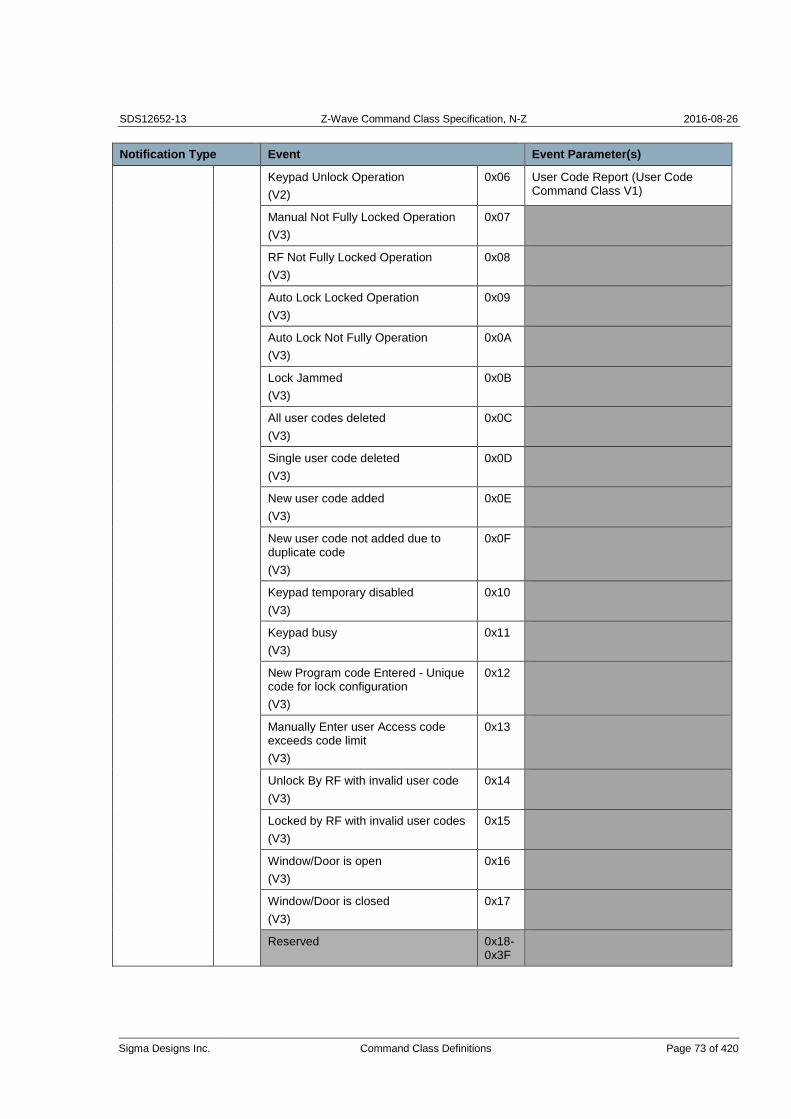
SDS12652-13 Z-Wave Command Class Specification, N-Z 2016-08-26
Sigma Designs Inc. Command Class Definitions Page 73 of 420
Notification Type Event Event Parameter(s)
Keypad Unlock Operation
(V2)
0x06 User Code Report (User Code Command Class V1)
Manual Not Fully Locked Operation
(V3)
0x07
RF Not Fully Locked Operation
(V3)
0x08
Auto Lock Locked Operation
(V3)
0x09
Auto Lock Not Fully Operation
(V3)
0x0A
Lock Jammed
(V3)
0x0B
All user codes deleted
(V3)
0x0C
Single user code deleted
(V3)
0x0D
New user code added
(V3)
0x0E
New user code not added due to duplicate code
(V3)
0x0F
Keypad temporary disabled
(V3)
0x10
Keypad busy
(V3)
0x11
New Program code Entered - Unique code for lock configuration
(V3)
0x12
Manually Enter user Access code exceeds code limit
(V3)
0x13
Unlock By RF with invalid user code
(V3)
0x14
Locked by RF with invalid user codes
(V3)
0x15
Window/Door is open
(V3)
0x16
Window/Door is closed
(V3)
0x17
Reserved 0x18- 0x3F

SDS12652-13 Z-Wave Command Class Specification, N-Z 2016-08-26
Sigma Designs Inc. Command Class Definitions Page 74 of 420
Notification Type Event Event Parameter(s)
Barrier performing Initialization process
(V4)
0x40 (1 byte)
0xFF = Performing Process
0x00 = Process Complete
0x01 – 0xFE = Reserved
Barrier operation (Open / Close) force has been exceeded.
(V4)
0x41
Barrier motor has exceeded manufacturer’s operational time limit
(V4)
0x42
(1 byte)
0x00-0x7F = 0sec-127sec
0x80-0xFE = 1min-127min
Barrier operation has exceeded physical mechanical limits. (For example: barrier has opened past the open limit)
(V4)
0x43
Barrier unable to perform requested operation due to UL requirements.
(V4)
0x44
Barrier Unattended operation has been disabled per UL requirements.
(V4)
0x45
Barrier failed to perform Requested operation, device malfunction
(V4)
0x46
Barrier Vacation Mode
(V4)
0x47 (1 byte)
0xFF = Mode Enabled
0x00 = Mode Disabled
0x01 – 0xFE = Reserved
Barrier Safety Beam Obstacle
(V4)
0x48 (1 byte) 0xFF = Obstruction 0x00 = No Obstruction
0x01 – 0xFE = Reserved
Barrier Sensor Not Detected / Supervisory Error
(V4)
0x49 (1 byte)
0x00 = Sensor not defined
0x01 – 0xFF = Sensor ID
Barrier Sensor Low Battery Warning
(V4)
0x4A (1 byte)
0x00 = Sensor not defined
0x01 – 0xFF = Sensor ID
Barrier detected short in Wall Station wires
(V4)
0x4B
Barrier associated with non-Z-wave remote control.
(V4)
0x4C
Unknown Event
(V2)
0xFE

SDS12652-13 Z-Wave Command Class Specification, N-Z 2016-08-26
Sigma Designs Inc. Command Class Definitions Page 75 of 420
Notification Type Event Event Parameter(s)
Home
Security
(V2)
0x07 Event inactive (push mode) / Previous Events cleared (pull mode)
(V4)
0x00 - Event identifier for the event which is no more active.
- If no Event Parameter is provided, there are no active events for the specified Notification Type.
Intrusion
(V2)
0x01 Node Location Report (Node Naming and Location Command Class, version 1)
Intrusion,
Unknown Location
(V2)
0x02
Tampering,
Product covering removed
(V2)
0x03
Tampering,
Invalid Code
(V2)
0x04
Glass Breakage
(V2)
0x05 Node Location Report (Node Naming and Location Command Class, version 1)
Glass Breakage,
Unknown Location
(V2)
0x06
Motion Detection
(V2)
0x07 Node Location Report (Node Naming and Location Command Class, version 1)
Motion Detection,
Unknown Location
(V4)
0x08
Tampering,
Product Moved
(V6)
0x09
Unknown Event
(V2)
0xFE
Power
Management
(V2)
0x08 Event inactive (push mode) / Previous Events cleared (pull mode)
(V4)
0x00 - Event identifier for the event which is no more active.
- If no Event Parameter is provided, there are no active events for the specified Notification Type.
Power has been applied
(V2)
0x01
AC mains disconnected
(V2)
0x02
AC mains re-connected
(V2)
0x03

SDS12652-13 Z-Wave Command Class Specification, N-Z 2016-08-26
Sigma Designs Inc. Command Class Definitions Page 76 of 420
Notification Type Event Event Parameter(s)
Surge detected
(V2)
0x04
Voltage Drop/Drift
(V2)
0x05
Over-current detected
(V3)
0x06
Over-voltage detected
(V3)
0x07
Over-load detected
(V3)
0x08
Load error
(V3)
0x09
Replace battery soon
(V3)
0x0A
Replace battery now
(V3)
0x0B
Battery is charging
(V4)
0x0C
Battery is fully charged
(V4)
0x0D
Charge battery soon
(V4)
0x0E
Charge battery now!
(V4)
0x0F
Unknown Event
(V2)
0xFE
System
(V2)
0x09 Event inactive (push mode) / Previous Events cleared (pull mode)
(V4)
0x00 - Event identifier for the event which is no more active.
- If no Event Parameter is provided, there are no active events for the specified Notification Type.
System hardware failure
(V2)
0x01
System software failure
(V2)
0x02
System hardware failure with manufacturer proprietary failure code
(V3)
0x03 Manufacturer proprietary system failure codes.
Cannot be listed in NIF. MUST be described in product manual.
System software failure with manufacturer proprietary failure code
(V3)
0x04 Manufacturer proprietary system failure codes.
Cannot be listed in NIF. MUST be described in product manual.
Heartbeat (V5) 0x05

SDS12652-13 Z-Wave Command Class Specification, N-Z 2016-08-26
Sigma Designs Inc. Command Class Definitions Page 77 of 420
Notification Type Event Event Parameter(s)
Tampering, (V5)
Product covering removed
0x06
Emergency Shutoff (V7) 0x07
Unknown Event
(V2)
0xFE
Emergency
Alarm
(V2)
0x0A Event inactive (push mode) / Previous Events cleared (pull mode)
(V4)
0x00 - Event identifier for the event which is no more active.
- If no Event Parameter is provided, there are no active events for the specified Notification Type.
Contact Police
(V2)
0x01
Contact Fire Service
(V2)
0x02
Contact Medical Service
(V2)
0x03
Unknown Event
(V2)
0xFE
Clock
(V2)
0x0B Event inactive (push mode) / Previous Events cleared (pull mode)
(V4)
0x00 - Event identifier for the event which is no more active.
- If no Event Parameter is provided, there are no active events for the specified Notification Type.
Wake Up Alert
(V2)
0x01
Timer Ended
(V3)
0x02
Time remaining
(V4)
0x03 Event Parm 1 = hour(s)
Event Parm 2 = minute(s)
Event Parm 3 = second(s)
Unknown Event
(V2)
0xFE
Appliance
(V4)
0x0C Event inactive (push mode) / Previous Events cleared (pull mode)
(V4)
0x00 - Event identifier for the event which is no more active.
- If no Event Parameter is provided, there are no active events for the specified Notification Type.
Program started
(V4)
0x01
Program in progress
(V4)
0x02
Program completed
(V4)
0x03

SDS12652-13 Z-Wave Command Class Specification, N-Z 2016-08-26
Sigma Designs Inc. Command Class Definitions Page 78 of 420
Notification Type Event Event Parameter(s)
Replace main filter
(V4)
0x04
Failure to set target temperature
(V4)
0x05
Supplying water
(V4)
0x06
Water supply failure
(V4)
0x07
Boiling
(V4)
0x08
Boiling failure
(V4)
0x09
Washing
(V4)
0x0A
Washing failure
(V4)
0x0B
Rinsing
(V4)
0x0C
Rinsing failure
(V4)
0x0D
Draining
(V4)
0x0E
Draining failure
(V4)
0x0F
Spinning
(V4)
0x10
Spinning failure
(V4)
0x11
Drying
(V4)
0x12
Drying failure
(V4)
0x13
Fan failure
(V4)
0x14
Compressor failure
(V4)
0x15
Unknown Event
(V4)
0xFE

SDS12652-13 Z-Wave Command Class Specification, N-Z 2016-08-26
Sigma Designs Inc. Command Class Definitions Page 79 of 420
Notification Type Event Event Parameter(s)
Home Health
(V4)
0x0D Event inactive (push mode) / Previous Events cleared (pull mode)
(V4)
0x00 - Event identifier for the event which is no more active.
- If no Event Parameter is provided, there are no active events for the specified Notification Type.
Leaving Bed
(V4)
0x01
Sitting on bed
(V4)
0x02
Lying on bed
(V4)
0x03
Posture changed
(V4)
0x04
Sitting on edge of bed
(V4)
0x05
Volatile Organic Compound level
(V4)
0x06 Event Parm 1 (1 byte) = pollution level
0x01 = Clean
0x02 = Slightly polluted
0x03 = Moderately polluted
0x04 = Highly polluted
Unknown Event
(V4)
0xFE
Siren (V6) 0x0E Event inactive (push mode) / Previous Events cleared (pull mode)
(V6)
0x00 - Event identifier for the event which is no more active.
- If no Event Parameter is provided, there are no active events for the specified Notification Type.
Siren Active
(V6)
0x01
Unknown Event
(V6)
0xFE
Water Valve (V7)
0x0F Event inactive (push mode) / Previous Events cleared (pull mode)
(V7)
0x00 - Event identifier for the event which is no more active.
- If no Event Parameter is provided, there are no active events for the specified Notification Type.
Valve Operation (V7)
0x01 Event Parm 1 = 0: Off 1: On
Master Valve Operation (V7)
0x02 Event Parm 1 = 0: Off 1: On
Valve Short Circuit (V7)
0x03
Master Valve Short Circuit (V7)
0x04

SDS12652-13 Z-Wave Command Class Specification, N-Z 2016-08-26
Sigma Designs Inc. Command Class Definitions Page 80 of 420
Notification Type Event Event Parameter(s)
Valve Current Alarm (V7)
0x05 Event Parm 1 = 1: No data 2: Below low threshold 3: Above high threshold 4: Max
Master Valve Current Alarm (V7)
0x06 Event Parm 1 = 1: No data 2: Below low threshold 3: Above high threshold 4: Max
Unknown Event
(V7)
0xFE
Weather Alarm (V7)
0x10 Event inactive (push mode) / Previous Events cleared (pull mode)
(V7)
0x00 - Event identifier for the event which is no more active.
- If no Event Parameter is provided, there are no active events for the specified Notification Type.
Rain Alarm (V7)
0x01
Moisture Alarm (V7)
0x02
Unknown Event
(V7)
0xFE
Irrigation (V7) 0x11 Event inactive (push mode) / Previous Events cleared (pull mode)
(V7)
0x00 - Event identifier for the event which is no more active.
- If no Event Parameter is provided, there are no active events for the specified Notification Type.
Schedule Started (V7)
0x01 Event Parm 1 = <Schedule ID>
Schedule Finished (V7)
0x02 Event Parm 1 = <Schedule ID>
Valve Table Run Started (V7)
0x03 Event Parm 1 = <Valve Table ID>
Valve Table Run Finished (V7)
0x04 Event Parm 1 = <Valve Table ID>
Device is not Configured (V7)
0x05
Unknown Event
(V7)
0xFE
Gas Alarm (V7) 0x12 Event inactive (push mode) / Previous Events cleared (pull mode)
(V7)
0x00 - Event identifier for the event which is no more active.
- If no Event Parameter is provided, there are no active events for the specified Notification Type.
Combustible Gas detected (V7)
0x01 Node Location Report (Node Naming and Location Command Class).
Combustible Gas detected, Unknown Location (V7)
0x02

SDS12652-13 Z-Wave Command Class Specification, N-Z 2016-08-26
Sigma Designs Inc. Command Class Definitions Page 81 of 420
Notification Type Event Event Parameter(s)
Toxic Gas detected (V7)
0x03 Node Location Report (Node Naming and Location Command Class).
Toxic Gas detected, Unknown Location (V7)
0x04
Gas Alarm Test (V7)
0x05
Replacement Required, Unspecified reason (V7)
0x06
Unknown Event
(V7)
0xFE
Request pending notification (Notification Get; pull mode)
(V2)
0xFF
All other values are reserved and MUST NOT be used by a sending node. Reserved values MUST be ignored by a receiving node.
The following identifiers MUST NOT be listed in the Bit Mask fields of Notification Supported Report and Event Supported Report commands:
Notification Type = 0xFF (“Return first detected notification on supported list”)
Event = 0xFE (“Unknown Event”)
Reserved values and special-purpose values MUST NOT be advertised in the Bit Mask fields by a sending node and MUST be ignored by a receiving node.
3.4.10.7 Detailed description: (Notification Type = Smoke Alarm) events
Smoke Alarm: Replacement Required, Unspecified reason (V5)
This event may be issued by an alarm device to advertise that its physical components are no more reliable, e.g. because of clogged filters.
Smoke Alarm: Replacement Required, End-of-life (V8)
This event may be issued by an alarm device to advertise that the device has reached the end of its designed lifetime. The device should no longer be used.
Smoke Alarm: Alarm Silenced (V8)
This event may be issued by an alarm device to advertise that the alarm has been silenced by a local user event.

SDS12652-13 Z-Wave Command Class Specification, N-Z 2016-08-26
Sigma Designs Inc. Command Class Definitions Page 82 of 420
Smoke Alarm: Maintenance required, Planned periodic inspection (V8)
This event may be issued by an alarm device to advertise that the device has reached the end of a designed maintenance interval. The device is should be serviced in order to stay reliable.
Smoke Alarm: Maintenance required, Dust in device (V8)
This event may be issued by an alarm device to advertise that the device has detected dust in its sensor. The device is not reliable until it has been serviced.
3.4.10.8 Detailed description: (Notification Type = CO Alarm) events
CO Alarm: Carbon monoxide Test (V5)
The Carbon monoxide Test event may be issued by an alarm device to advertise that the test mode of the device has been activated. The activation may be manual or via signaling.
A receiving application SHOULD NOT activate any alarms in response to this event.
CO Alarm: Replacement Required, Unspecified reason (V5)
This event may be issued by an alarm device to advertise that its physical components are no more reliable, e.g. because of clogged filters.
3.4.10.9 Detailed description: (Notification Type = CO2 Alarm) events
CO2 Alarm: Carbon dioxide Test (V5)
The Carbon dioxide Test event may be issued by an alarm device to advertise that the test mode of the device has been activated. The activation may be manual or via signaling.
A receiving application SHOULD NOT activate any alarms in response to this event.
CO2 Alarm: Replacement Required, Unspecified reason (V5)
This event may be issued by an alarm device to advertise that its physical components are no more reliable, e.g. because of clogged filters.
3.4.10.10 Detailed description: (Notification Type = Heat Alarm) events
Heat Alarm: Heat Alarm Test (V8)
This event may be issued by an alarm device to advertise that the local test function has been activated.
Heat Alarm: Replacement Required, End-of-life (V8)
This event may be issued by an alarm device to advertise that the device has reached the end of its designed lifetime. The device should no longer be used.
Heat Alarm: Alarm Silenced (V8)
This event may be issued by an alarm device to advertise that the alarm has been silenced by a local user event.

SDS12652-13 Z-Wave Command Class Specification, N-Z 2016-08-26
Sigma Designs Inc. Command Class Definitions Page 83 of 420
Heat Alarm: Maintenance required, Dust in device (V8)
This event may be issued by an alarm device to advertise that the device has detected dust in its sensor. The device is not reliable until it has been serviced.
Heat Alarm: Maintenance required, Planned periodic inspection (V8)
This event may be issued by an alarm device to advertise that the device has reached the end of a designed maintenance interval. The device is should be serviced in order to stay reliable.
3.4.10.11 Detailed description: (Notification Type = System) events
System: Heartbeat (V5)
The Heartbeat event may be issued by a device to advertise that the device is still alive.
System: Tampering; Product covering removed (V5)
The Product covering removed event may be issued by a device to advertise that its physical enclosure has been compromised. This may, for instance, indicate a security threat or that a user is trying to modify a metering device.
Note that a similar event is defined for the Home Security Notification Type. If a device implements other events for the Home Security Notification Type, the device should issue the Tampering event defined for the Home Security Notification Type.
3.4.10.12 Detailed description: (Notification Type = Siren) events
Siren: Siren Active (V6)
This Event indicates that a siren or sound within a device is active. This may be a Siren within a smoke sensor that goes active when smoke is detected. Or a beeping within a power switch to indicate over-current detected. The siren may switch Off automatically or based on user interaction. This can be reported through Notification Type Siren and Event 0x00.
3.4.10.13 Detailed description: (Event Parameters = User Code Report and Node Location Report)
The User Code Report and Node Location Report are used as Event Parameter for various Events. The Event Parameters must include the full Report including The Command Class Identifier and Command Identifier.
Example
A User Code Report is used as Event Parameter in a Keypad Lock/Unlock Operation. The User Code has the following parameters:
Command_Class =_User_Code = 0x63 Command = User_Code_Report = 0x03 User Identifier = 0x01, User ID Status = 0x01, User Code = 0x30, 0x30, 0x30, 0x30
The complete User Code Report therefore comprises the following Bytes: [0x63, 0x03, 0x01, 0x01, 0x30, 0x30, 0x30, 0x30].

SDS12652-13 Z-Wave Command Class Specification, N-Z 2016-08-26
Sigma Designs Inc. Command Class Definitions Page 84 of 420
3.4.10.14 Detailed description: “Event Inactive” Parameter
The parameter allows the device to specify the Event which is no more active.
Supporting nodes implementing version 8 or newer of the Notification Command Class MUST issue an Event Inactive Notification when leaving a state that was advertised by another notification. For instance, the “Smoke Detected” event is be followed by an “Event Inactive (Smoke Detected)” event when the smoke detected state is cleared in the sensor. A sensor MAY send repeated state Notifications without sending any Event Inactive Notification to indicate that a given state is still active. For instance, a smoke sensor can send “Smoke Detected” every five minutes to indicate that the state has not been cleared.
3.4.10.15 Sequence (1 bit)
This field is used to advertise the presence of the “Sequence Number” field.
The value 0 MUST indicate that no “Sequence Number” field is appended after the “Event Parameter” field(s).
The value 1 MUST indicate that a “Sequence Number” field is appended after the “Event Parameter” field(s).
3.4.10.16 Event Parameters Length (5 bits)
This field MUST advertise the length of the Event Parameters fields.
The value 0 MUST indicate that no Event Parameter fields are appended after the Event Parameters Length field.
Values in the range 1-31 MUST indicate the number of Event Parameter field(s) appended after the Event Parameters Length field.
3.4.10.17 Event Parameter 1 … Event Parameter N (N * Bytes)
The Event Parameter fields may carry an encapsulated command. The Event Parameter(s) MUST include the complete command structure, i.e. Command Class ID, Command ID and all relevant parameters.
The device MUST advertise the command class of all such embedded commands in the Node Information Frame (NIF).
If the “Event Parameters Length” field is not equal to ‘0’, the Event Parameter fields encapsulate information relating to the Notification Type and Event.
Table 33 provides an example of event parameter encapsulation.
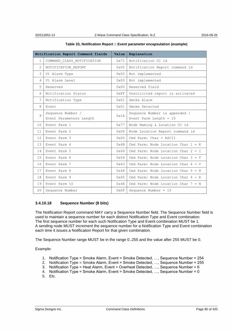
SDS12652-13 Z-Wave Command Class Specification, N-Z 2016-08-26
Sigma Designs Inc. Command Class Definitions Page 85 of 420
Table 33, Notification Report :: Event parameter encapsulation (example)
Notification Report Command fields Value Explanation
1 COMMAND_CLASS_NOTIFICATION 0x71 Notification CC id
2 NOTIFICATION_REPORT 0x05 Notification Report command id
3 V1 Alarm Type 0x00 Not implemented
4 V1 Alarm Level 0x00 Not implemented
5 Reserved 0x00 Reserved field
6 Notification Status 0xFF Unsolicited report is activated
7 Notification Type 0x01 Smoke Alarm
8 Event 0x01 Smoke Detected
9 Sequence Number /
Event Parameters Length 0x1A
Sequence Number is appended /
Event Parm Length = 10
10 Event Parm 1 0x77 Node Naming & Location CC id
11 Event Parm 2 0x06 Node Location Report command id
12 Event Parm 3 0x00 Cmd Parm: Char = ASCII
13 Event Parm 4 0x4B Cmd Parm: Node Location Char 1 = K
14 Event Parm 5 0x49 Cmd Parm: Node Location Char 2 = I
15 Event Parm 6 0x54 Cmd Parm: Node Location Char 3 = T
16 Event Parm 7 0x43 Cmd Parm: Node Location Char 4 = C
17 Event Parm 8 0x48 Cmd Parm: Node Location Char 5 = H
18 Event Parm 9 0x45 Cmd Parm: Node Location Char 6 = E
19 Event Parm 10 0x4E Cmd Parm: Node Location Char 7 = N
20 Sequence Number 0x0F Sequence Number = 15
3.4.10.18 Sequence Number (8 bits)
The Notification Report command MAY carry a Sequence Number field. The Sequence Number field is used to maintain a sequence number for each distinct Notification Type and Event combination. The first sequence number for each such Notification Type and Event combination MUST be 1. A sending node MUST increment the sequence number for a Notification Type and Event combination each time it issues a Notification Report for that given combination.
The Sequence Number range MUST be in the range 0..255 and the value after 255 MUST be 0.
Example:
1. Notification Type = Smoke Alarm, Event = Smoke Detected, …, Sequence Number = 254 2. Notification Type = Smoke Alarm, Event = Smoke Detected, …, Sequence Number = 255 3. Notification Type = Heat Alarm, Event = Overheat Detected, …, Sequence Number = 6 4. Notification Type = Smoke Alarm, Event = Smoke Detected, …, Sequence Number = 0 5. Etc.

SDS12652-13 Z-Wave Command Class Specification, N-Z 2016-08-26
Sigma Designs Inc. Command Class Definitions Page 86 of 420
3.4.11 Notification Supported Get Command
This command is used to request supported Notification Types.
The Notification Supported Report Command MUST be returned in response to this command.
This command MUST NOT be issued via multicast addressing. A receiving node MUST NOT return a response if this command is received via multicast addressing. The Z-Wave Multicast frame, the broadcast NodeID and the Multi Channel multi-End Point destination are all considered multicast addressing methods.
7 6 5 4 3 2 1 0
Command Class = COMMAND_CLASS_NOTIFICATION
Command = NOTIFICATION_SUPPORTED_GET
3.4.12 Notification Supported Report Command
The Notification Supported Report Command is used to advertise supported Notification Types.
7 6 5 4 3 2 1 0
Command Class = COMMAND_CLASS_NOTIFICATION
Command = NOTIFICATION_SUPPORTED_REPORT
V1 Alarm
Reserved Number of Bit Masks
Bit Mask 1
...
Bit Mask N
V1 Alarm (1 bit)
0 = the device implements only Notification CC V2 Notification Types.
1 = the device implements Notification CC V2 Notification Typesas well as proprietary Alarm CC V1 Alarm Types and Alarm Levels.
Number of Bit Masks (5 bits)
This field MUST advertise the number of bit mask fields actually carried in the Notification Supported Report command.
Bit Mask 1 .. Bit Mask N (N Bytes)
The Bit Mask fields describe the supported Notification Type(s) by the device. The number of Bit Mask fields MUST match the value advertised in the Number of Bit Masks field.
Bit 0 in Bit Mask 1 is not allocated to any Notification Type and MUST be set to zero.
Bit 1 in Bit Mask 1 indicates if Notification Type = Smoke Alarm (0x01) is supported.
Bit 2 in Bit Mask 1 indicates if Notification Type = CO Alarm (0x02) is supported.
Bit 3 in Bit Mask 1 indicates if Notification Type = CO2 Alarm (0x03) is supported
…

SDS12652-13 Z-Wave Command Class Specification, N-Z 2016-08-26
Sigma Designs Inc. Command Class Definitions Page 87 of 420
If the Notification Type is supported the corresponding bit MUST be set to 1, If the Notification Type is not supported the corresponding bit MUST be set to 0.
The Notification Type value 0xFF is a special-purpose value. Reserved values and special-purpose values MUST NOT be advertised in the Bit Mask fields by a sending node and MUST be ignored by a receiving node.
Note that the mapping of bit 1 to Notification Type =1 differs from the support mapping used by the Multilevel Sensor Command Class. The Multilevel Sensor Command Class maps bit 0 to Sensor Type = 1.
3.4.13 Event Supported Get Command
The Event Supported Get Command is used to request the supported Events for a specified Notification Type.
The Event Supported Report Command MUST be returned in response to an this command.
This command MUST NOT be issued via multicast addressing. A receiving node MUST NOT return a response if this command is received via multicast addressing. The Z-Wave Multicast frame, the broadcast NodeID and the Multi Channel multi-End Point destination are all considered multicast addressing methods.
7 6 5 4 3 2 1 0
Command Class = COMMAND_CLASS_NOTIFICATION
Command = EVENT_SUPPORTED_GET
Notification Type
Notification Type (8 bits)
See Table 32.
If a device receives an un-supported Notification Type or Notification Type = 0xFF, the receiving node MUST respond with Event Supported Report command with the Notification Type specified in the Event Supported Get command and the Number of Bit Masks field set to 0.

SDS12652-13 Z-Wave Command Class Specification, N-Z 2016-08-26
Sigma Designs Inc. Command Class Definitions Page 88 of 420
3.4.14 Event Supported Report Command
The Event Supported Report Command is used to advertise supported Events.
7 6 5 4 3 2 1 0
Command Class = COMMAND_CLASS_NOTIFICATION
Command = EVENT_SUPPORTED_REPORT
Notification Type
Reserved Number of Bit Masks
Bit Mask 1
...
Bit Mask N
Notification Type (8 bits)
See Table 32.
Number of Bit Masks (5 bits)
This field MUST advertise the number of bit mask fields actually carried in the Event Supported Report command.
The value MUST be in the range 1-31.
Bit Mask 1 .. Bit Mask N (N * Bytes)
The Bit Mask fields MUST advertise the supported Events for the actual advertised Notification Type field. The number of Bit Mask fields MUST match the value advertised in the Number of Bit Masks field.
The bit value ‘1’ MUST indicate that the actual event is supported. The bit value ‘0’ MUST indicate that the actual event is not supported.
Example: Notification Type = Heat Alarm (0x04):
Bit 0 in Bit Mask 1 field is not allocated to any event and must therefore be set to zero.
Bit 1 in Bit Mask 1 field indicates support for Overheat detected (0x01).
Bit 2 in Bit Mask 1 field indicates support for Overheat, unknown loc. (0x02).
Bit 3 in Bit Mask 1 field indicates support for Rapid temp rise (0x03).
…
The Event value 0xFE is a special-purpose value. Reserved values and special-purpose values MUST NOT be advertised in the Bit Mask fields by a sending node and MUST be ignored by a receiving node.
Note that the mapping of bit 1 to Event Type =1 differs from the support mapping used by the Multilevel Sensor Command Class. The Multilevel Sensor Command Class maps bit 0 to Sensor Type = 1.

SDS12652-13 Z-Wave Command Class Specification, N-Z 2016-08-26
Sigma Designs Inc. Command Class Definitions Page 89 of 420
3.5 Powerlevel Command Class, version 1
The Powerlevel Command Class defines RF transmit power controlling Commands useful when installing or testing a network. The Commands makes it possible for supporting controllers to set/get the RF transmit power level of a node and test specific links between nodes with a specific RF transmit power level.
NOTE: This Command Class is only used in an installation or test situation.
3.5.1 Powerlevel Set Command
The Powerlevel Set Command is used to set the power level indicator value, which should be used by the node when transmitting RF, and the timeout for this power level indicator value before returning the power level defined by the application.
7 6 5 4 3 2 1 0
Command Class = COMMAND_CLASS_POWERLEVEL
Command = POWERLEVEL_SET
Power level
Timeout
Power level (8 bits)
This field indicates the power level value that the receiving node MUST set.
This field MUST be encoded according to Table 34:
Table 34, Powerlevel Set::Power level encoding
Value Description
0x00 NormalPower
0x01 minus1dBm
0x02 minus2dBm
0x03 minus3dBm
0x04 minus4dBm
0x05 minus5dBm
0x06 minus6dBm
0x07 minus7dBm
0x08 minus8dBm
0x09 minus9dBm
All other values are reserved and MUST NOT be used by a sending node. Reserved values MUST be ignored by a receiving node.

SDS12652-13 Z-Wave Command Class Specification, N-Z 2016-08-26
Sigma Designs Inc. Command Class Definitions Page 90 of 420
Timeout value is ignored if Power level is set to normalPower.
Timeout (8 bits)
The time in seconds the node should keep the Power level before resetting to normalPower level. It is fundamental, that the timeout IS implemented and followed by the application, for keeping the network consistent. Valid values are 1-255 resulting in timeouts from 1 second to 255 seconds.
3.5.2 Powerlevel Get Command
The Powerlevel Get Command is used to request the current power level value.
The Powerlevel Report Command MUST be returned in response to this command.
This command MUST NOT be issued via multicast addressing. A receiving node MUST NOT return a response if this command is received via multicast addressing. The Z-Wave Multicast frame, the broadcast NodeID and the Multi Channel multi-End Point destination are all considered multicast addressing methods.
7 6 5 4 3 2 1 0
Command Class = COMMAND_CLASS_POWERLEVEL
Command = POWERLEVEL_GET

SDS12652-13 Z-Wave Command Class Specification, N-Z 2016-08-26
Sigma Designs Inc. Command Class Definitions Page 91 of 420
3.5.3 Powerlevel Report Command
This command is used to advertise the current power level.
7 6 5 4 3 2 1 0
Command Class = COMMAND_CLASS_POWERLEVEL
Command = POWERLEVEL_REPORT
Power level
Timeout
Power level (8 bits)
This value is the current power level indicator value in effect on the node.
This field MUST be encoded according to Table 34.
If the returned value is normalPower, the timeout value is ignored.
Timeout (8 bits)
The time in seconds the node has back at Power level before resetting to normal Power level.
3.5.4 Powerlevel Test Node Set Command
The Powerlevel Test Node Set Command is used to instruct the destination node to transmit a number of test frames to the specified NodeID with the RF power level specified. After the test frame transmissions the RF power level is reset to normal and the result (number of acknowledged test frames) is saved for subsequent read-back. The result of the test may be requested with a Powerlevel Test Node Get Command.
7 6 5 4 3 2 1 0
Command Class = COMMAND_CLASS_POWERLEVEL
Command = POWERLEVEL_TEST_NODE_SET
Test NodeID
Power level
Test frame count (MSB)
Test frame count (LSB)
Test NodeID (8 bits)
The test NodeID that should receive the test frames.
Power level (8 bits)
The power level indicator value to use in the test frame transmission.

SDS12652-13 Z-Wave Command Class Specification, N-Z 2016-08-26
Sigma Designs Inc. Command Class Definitions Page 92 of 420
This field MUST be encoded according to Table 34.
Test frame count (16 bits)
The Test frame count field contains the number of test frames to transmit to the Test NodeID. The first byte is the most significant byte. Valid Test frame count range is 1-65535.
3.5.5 Powerlevel Test Node Get Command
The Powerlevel Test Node Get Command is used to request the result of the latest Powerlevel Test.
The Powerlevel Test Node Report Command MUST be returned in response to this command.
This command MUST NOT be issued via multicast addressing. A receiving node MUST NOT return a response if this command is received via multicast addressing. The Z-Wave Multicast frame, the broadcast NodeID and the Multi Channel multi-End Point destination are all considered multicast addressing methods.
7 6 5 4 3 2 1 0
Command Class = COMMAND_CLASS_POWERLEVEL
Command = POWERLEVEL_TEST_NODE_GET

SDS12652-13 Z-Wave Command Class Specification, N-Z 2016-08-26
Sigma Designs Inc. Command Class Definitions Page 93 of 420
3.5.6 Powerlevel Test Node Report Command
This command is used to report the latest result of a test frame transmission started by the Powerlevel Test Node Set Command.
7 6 5 4 3 2 1 0
Command Class = COMMAND_CLASS_POWERLEVEL
Command = POWERLEVEL_TEST_NODE_REPORT
Test NodeID
Status of operation
Test frame acknowledged count (MSB)
Test frame acknowledged count (LSB)
Test NodeID (8 bits)
This field advertises the NodeID of the node, which is or has been under test.
If a test has been performed, this field MUST reflect the NodeID used in the last test initiated with the Powerlevel Test Node Set Command.
If no test has been performed, this field MUST be set to 0. In this case, the Status of operation and Test frame acknowledged count fields MAY be ignored.
Status of operation (8 bits)
This field indicates the result of the last test initiated with the Powerlevel Test Node Set Command. It MUST be encoded according to Table 35..
Table 35,Powerlevel Test Node Report::Status of operation encoding
Value Description
0x00 Test Failed No frame was returned during the test
0x01 Test Success At least 1 frame was returned during the test
0x02 Test in Progress The test is still ongoing
All other values are reserved and MUST NOT be used by a sending node. Reserved values MUST be ignored by a receiving node.
Test frame acknowledged count (16 bits)
This field indicates the number of test frames transmitted, which the Test NodeID has acknowledged. The first byte is the most significant byte.

SDS12652-13 Z-Wave Command Class Specification, N-Z 2016-08-26
Sigma Designs Inc. Command Class Definitions Page 94 of 420
3.6 Prepayment Command Class, version 1
The Prepayment Command Class defines the Commands necessary to implement a Z-Wave encapsulation of Prepayment data and to distribute prepayment information between devices
3.6.1 Prepayment Balance Get Command
The Prepayment Balance Get Command is used to request the balance of the Prepayment.
The Prepayment Balance Report Command MUST be returned in response to this command.
This command MUST NOT be issued via multicast addressing. A receiving node MUST NOT return a response if this command is received via multicast addressing. The Z-Wave Multicast frame, the broadcast NodeID and the Multi Channel multi-End Point destination are all considered multicast addressing methods.
7 6 5 4 3 2 1 0
Command Class = COMMAND_CLASS_PREPAYMENT
Command = PREPAYMENT_BALANCE_GET
Balance Type Reserved
Balance Type (2 bits)
The field specifies which balance type is requested in the response report. The available balance types may be requested using the Prepayment Supported Get Command.
Table 36, Prepayment Balance Get::Balance Type encoding
Value Balance Type
0x00 Utility Balance
0x01 Monetary Balance
All other values are reserved and MUST NOT be used by a sending node. Reserved values MUST be ignored by a receiving node.
3.6.2 Prepayment Balance Report Command
The Prepayment Balance Report Command is used to report the current balances.
The report includes the following main elements:
- Balance
- Debt
- Emergency Credit
The elements MAY be given in monetary values or in utility units depending on the Balance Type field.

SDS12652-13 Z-Wave Command Class Specification, N-Z 2016-08-26
Sigma Designs Inc. Command Class Definitions Page 95 of 420
7 6 5 4 3 2 1 0
Command Class = COMMAND_CLASS_PREPAYMENT
Command = PREPAYMENT_BALANCE_REPORT
Balance Type Meter type
Balance Precision Scale
Balance Value 1
Balance Value 2
Balance Value 3
Balance Value 4
Debt Precision Reserved
Debt 1
Debt 2
Debt 3
Debt 4
Emer. Credit Precision Reserved
Emer. Credit 1
Emer. Credit 2
Emer. Credit 3
Emer. Credit 4
Currency 1
Currency 2
Currency 3
Debt Recovery Percentage
Balance Type (2 bits)
The field specifies which type of balance is given in the report.
All available Balance Types may be found in the section 3.6.1 Prepayment Balance Get Command.
Meter Type (6 bits)
Meter Type specifies the type of metering device the command originates. Meter Type defined as the Meter Type variable; refer to [2] for a definition of the variable.
Scale (5 bits)
The Scale used to indicate the scale (unit) of the balance, debt and emergency credit value in the report. Scale field only used for a report of type “Utility Balance”, for other reports set the scale to 0x1F. The Scale parameter is of the variable type Meter Scale; refer to the Meter Table Current Data Report Command.

SDS12652-13 Z-Wave Command Class Specification, N-Z 2016-08-26
Sigma Designs Inc. Command Class Definitions Page 96 of 420
Currency (3 bytes)
This field advertises the currency code. Reports of the type “Monetary Balance” MUST advertise currency codes complying with ISO 4217. Other report types MUST advertise a currency code of “XXX”.
Table 37, Prepayment Balance Report::Currency examples
Currency Code Currency 1 Currency 2 Currency 3
Pound sterling (ISO 4217) G B P
US Dollar (ISO 4217) U S D
No Currency X X X
Balance, Debt and Emergency Credit Precision (3 bits)
The precision field describes what the precision of the value is. The number indicates the number of decimals. The decimal value 1025 with precision 2 is therefore equal to 10.25.
Balance, Debt and Emergency Credit (32 bits)
The Balance, Debt and Emergency Credit fields MUST be encoded as 32 bit signed integers. The first byte MUST carry most significant byte. Table 38shows signed decimal values together with their hexadecimal equivalents.
Table 38, Prepayment Balance Report::Balance, Debt and Emergency Credit encoding
Signed integer, 4 bytes
Decimal Hexadecimal
2147483647 0x7FFFFFFF
.. ..
1073741823 0x3FFFFFFF
.. ..
1 0x00000001
0 0x00000000
-1 0xFFFFFFFF
.. ..
-1073741823 0xC0000001
.. ..
-2147483648 0x80000000
Debt Recovery Percentage (8 bits)

SDS12652-13 Z-Wave Command Class Specification, N-Z 2016-08-26
Sigma Designs Inc. Command Class Definitions Page 97 of 420
The Debt Recovery Percentage indicates the percentage of the payment that is for debt recovery. This can take the value from 0 – 50%, the value is always given with a precision of 0 decimal places. The value 0xFF indicates that this field is unspecified.
This field is only used for only used for a report of type “Monetary Balance”. For other reports this field MUST be set to 0xFF (unspecified).
3.6.3 Prepayment Supported Get Command
The Prepayment Supported Get Command is used to request type of Balance Reports that are available in the device.
The Prepayment Supported Report Command MUST be returned in response to this command.
This command MUST NOT be issued via multicast addressing. A receiving node MUST NOT return a response if this command is received via multicast addressing. The Z-Wave Multicast frame, the broadcast NodeID and the Multi Channel multi-End Point destination are all considered multicast addressing methods.
7 6 5 4 3 2 1 0
Command Class = COMMAND_CLASS_PREPAYMENT
Command = PREPAYMENT_SUPPORTED_GET
3.6.4 Prepayment Supported Report Command
The Prepayment Supported Report Command reports the types of Balance Reports that are available in the device.
7 6 5 4 3 2 1 0
Command Class = COMMAND_CLASS_PREPAYMENT
Command = Command = PREPAYMENT_SUPPORTED_REPORT
Reserved Bit Mask
Balance Types Supported
Bit Mask - Balance Types Supported (8 bits)
The Bit Mask - Balance Types Supported byte describes the type of Balance Reports that are available in the device.
Bit 0 in Bit Mask is used to indicate if the Balance Report Type “Utility Balance” is supported, 0 indicating not supported and 1 indicating supported. Bit 1 in the Bit Mask is used to indicate if the Balance Report Type “Monetary Balance” is available in the device, 0 indicating not supported and 1 indicating supported.
All available Balance Types may be found in the section 3.6.1 Prepayment Balance Get Command.

SDS12652-13 Z-Wave Command Class Specification, N-Z 2016-08-26
Sigma Designs Inc. Command Class Definitions Page 98 of 420
3.7 Prepayment Encapsulation Command Class, version 1
The Prepayment Encapsulation Command Class is used to smartcard preinstalled security mechanisms.
3.7.1 Prepayment Encapsulation Command
The Prepayment Encapsulation Command is used to encapsulate Smart card related data communication (e.g. between a Card reader and Meter), allowing the smartcard preinstalled security mechanisms to be applied transparent to Z-Wave.
7 6 5 4 3 2 1 0
Command Class = COMMAND_CLASS_PREPAYMENT_ENCAPSULATION
Command = CMD_ENCAPSULATION
Data1
...
Data N
Data (N bytes)
Contains prepayment smart card data.

SDS12652-13 Z-Wave Command Class Specification, N-Z 2016-08-26
Sigma Designs Inc. Command Class Definitions Page 99 of 420
3.8 Proprietary Command Class, version 1 [DEPRECATED]
THIS COMMAND CLASS HAS BEEN DEPRECATED
A device MAY implement this command class, but it is RECOMMENDED that new implementations use the Manufacturer Proprietary Command Class. If implementing this command class, it is RECOMMENDED that the Manufacturer Proprietary Command Class is also implemented.
The Proprietary Command Class is used to transfer data between devices. The data content MUST be vendor specific and commands MUST NOT provide any value-add with respect to the Home Automation application in general.
3.8.1 Proprietary Set Command
The Proprietary Set Command is used to transfer data to a device.
7 6 5 4 3 2 1 0
Command Class = COMMAND_CLASS_PROPRIETARY
Command = PROPRIETARY_SET
Data 1
…
Data N
Data (N bytes)
The data fields may be used to set various data in the device. The number of data fields transmitted MUST be determined from the length field in the frame.

SDS12652-13 Z-Wave Command Class Specification, N-Z 2016-08-26
Sigma Designs Inc. Command Class Definitions Page 100 of 420
3.8.2 Proprietary Get Command
The Proprietary Get Command is used to request data from a device.
The Proprietary Report Command MUST be returned in response to this command.
This command MUST NOT be issued via multicast addressing. A receiving node MUST NOT return a response if this command is received via multicast addressing. The Z-Wave Multicast frame, the broadcast NodeID and the Multi Channel multi-End Point destination are all considered multicast addressing methods.
7 6 5 4 3 2 1 0
Command Class = COMMAND_CLASS_PROPRIETARY
Command = PROPRIETARY_GET
Data 1
…
Data N
Data (N bytes)
Refer to explanation under the Proprietary Set Command.
3.8.3 Proprietary Report Command
The Proprietary Report Command is used to retrieve various data from a device.
7 6 5 4 3 2 1 0
Command Class = COMMAND_CLASS_PROPRIETARY
Command = PROPRIETARY_REPORT
Data 1
…
Data N
Data (N bytes)
Refer to explanation under the Proprietary Set Command.

SDS12652-13 Z-Wave Command Class Specification, N-Z 2016-08-26
Sigma Designs Inc. Command Class Definitions Page 101 of 420
3.9 Protection Command Class, version 1
The Protection Command Class version 1 used to protect a device against unintentional control by e.g. a child.
3.9.1 Protection Set Command
The Protection Set Command is used to set the protection state in a device.
7 6 5 4 3 2 1 0
Command Class = COMMAND_CLASS_PROTECTION
Command = PROTECTION_SET
Protection State
Protection State (8 bits)
The Protection State field used to set the protection state of the device.
Table 39, Protection Set::Protection State encoding
Protection State Description
0x00 Unprotected - The device is not protected, and may be operated normally via the user interface.
0x01 Protection by sequence - The device is protected by altering the way the device normally is operated into a more complicated sequence of actions, e.g. if a device normally is controlled by a single press of a button on the device it might be changed to require 3 rapid presses on a button to control it.
0x02 No operation possible - It is not possible at all to control a device directly via the user interface.
All other values are reserved and MUST NOT be used by a sending node. Reserved values MUST be ignored by a receiving node.
Control via Z-Wave is always possible independently of the protection state.

SDS12652-13 Z-Wave Command Class Specification, N-Z 2016-08-26
Sigma Designs Inc. Command Class Definitions Page 102 of 420
3.9.2 Protection Get Command
The Protection Get Command is used to request the protection state from a device.
The Protection Report Command MUST be returned in response to this command.
This command MUST NOT be issued via multicast addressing. A receiving node MUST NOT return a response if this command is received via multicast addressing. The Z-Wave Multicast frame, the broadcast NodeID and the Multi Channel multi-End Point destination are all considered multicast addressing methods.
7 6 5 4 3 2 1 0
Command Class = COMMAND_CLASS_PROTECTION
Command = PROTECTION_GET
3.9.3 Protection Report Command
The Protection Report Command is used to report the protection state of a device.
7 6 5 4 3 2 1 0
Command Class = COMMAND_CLASS_PROTECTION
Command = PROTECTION_REPORT
Protection State
Protection State (8 bits)
Refer to explanation under Protection Get Command.

SDS12652-13 Z-Wave Command Class Specification, N-Z 2016-08-26
Sigma Designs Inc. Command Class Definitions Page 103 of 420
3.10 Protection Command Class, version 2
The Protection Command Class version 2 is extended to specify whether a device may be controlled via RF Commands or not. When a video recorder is powered by an outlet that can be controlled by RF the user would like to prevent the video recorder from being turned off when it is recording her/his favorite show. In this case the Protection Command Class version 2 may be used to protect the outlet from being turned off by setting the outlet in “No RF Control” state.
The following Commands have been added or changed in version 2. The Commands not mentioned remain unchanged.
This Command Class is intended for convenience applications. The Command Class SHOULD NOT be used for safety critical applications.
3.10.1 Protection Set Command
The Protection Set Command is used to set the protection state in a device.
7 6 5 4 3 2 1 0
Command Class = COMMAND_CLASS_PROTECTION
Command = PROTECTION_SET
Reserved Local Protection State
Reserved RF Protection State
Local Protection State (4 bits)
The Local Protection State field used to set the protection state of the device.
Table 40, Protection Set::Local Protection State encoding
Local Protection State
Description
0 Unprotected - The device is not protected, and may be operated normally via the user interface.
1 Protection by sequence - The device is protected by altering the way the device normally is operated into a more complicated sequence of actions, e.g. if a device normally is controlled by a single press of a button on the device it might be changed to require 3 rapid presses on a button to control it.
2 No operation possible - It is not possible at all to control a device directly via the user interface.
All other values are reserved and MUST NOT be used by a sending node. Reserved values MUST be ignored by a receiving node.Note: Local Protection can only protect a device from “normal operation”. This means only the operation that is intended by the application of the device. It is NOT allowed to protect the device from network functionalities. The device cannot be protected from being put into learn mode nor from sending out the NIF.
RF Protection State (4 bits)

SDS12652-13 Z-Wave Command Class Specification, N-Z 2016-08-26
Sigma Designs Inc. Command Class Definitions Page 104 of 420
The RF Protection State field used to set the RF protection state of the device. In the case where a device set into a RF Protection State which instructs the device not to answer to a “normal operation” Command, the device MUST return the Application Rejected Request Command (Status = 0) of the Application Status Command Class. Refer to the Application Status Command Class.
Table 41, Protection Set::RF Protection State
RF Protection State
Description
0 Unprotected - The device MUST accept and respond to all RF Commands.
1 No RF control - all runtime Commands are ignored by the device. The device MUST still respond with status on requests.
2 No RF response at all. The device will not even reply to status requests.
All other values are reserved and MUST NOT be used by a sending node. Reserved values MUST be ignored by a receiving node.Note: – It is only possible to un-protect the device with the Protection Set Command. It is not allowed ignore Protection Commands. If a device is excluded from the network, the protection states MUST be reset.
3.10.2 Protection Report Command
The Protection Report Command is used to report the protection state of a device.
7 6 5 4 3 2 1 0
Command Class = COMMAND_CLASS_PROTECTION
Command = PROTECTION_REPORT
Reserved Local Protection State
Reserved RF Protection State
For field description, refer to 3.10.1 Protection Set Command.
3.10.3 Protection Supported Get Command
This command is used to query supported protection capabilities.
The Protection Supported Report Command MUST be returned in response to this command.
This command MUST NOT be issued via multicast addressing. A receiving node MUST NOT return a response if this command is received via multicast addressing. The Z-Wave Multicast frame, the broadcast NodeID and the Multi Channel multi-End Point destination are all considered multicast addressing methods.
7 6 5 4 3 2 1 0
Command Class = COMMAND_CLASS_PROTECTION
Command = PROTECTION_SUPPORTED_GET

SDS12652-13 Z-Wave Command Class Specification, N-Z 2016-08-26
Sigma Designs Inc. Command Class Definitions Page 105 of 420
3.10.4 Protection Supported Report Command
This command is used to advertise supported protection capabilities.
7 6 5 4 3 2 1 0
Command Class = COMMAND_CLASS_PROTECTION
Command = PROTECTION_SUPPORTED_REPORT
Reserved Exclusive Control
Timeout
Local Protection State Byte 1
Local Protection State Byte 2
RF Protection State Byte 1
RF Protection State Byte 2
Local Protection State Byte (2 bytes)
The list of all Local Protection States may be found in section 3.10.1. The two bytes MUST be interpreted as bit masks where byte 1 bit 0 represent Local Protection State 0, byte 1 bit 1 represent Protection State 1, byte 2 bit 0 represent Protection State 8 etc.
RF Protection State Byte (2 bytes)
The list of all RF Protection States may be found in section 3.10.1. The two bytes MUST be interpreted as bit masks where byte 1 bit 0 represent RF Protection State 0, byte 1 bit 1 represent Protection State 1, byte 2 bit 0 represent Protection State 8 etc.
Exclusive Control (1 bit)
When this bit is set to 1 the device support Exclusive Control. When Exclusive Control is supported the device MUST support the Commands Protection Exclusive Control Set, Get and Report described below.
Timeout (1 bit)
When this bit is set to 1 the device supports a timeout for RF Protection State. When the timeout is supported the device MUST support the Commands Protection Timeout Set, Get and Report described below.

SDS12652-13 Z-Wave Command Class Specification, N-Z 2016-08-26
Sigma Designs Inc. Command Class Definitions Page 106 of 420
3.10.5 Protection Exclusive Control
The Protection Exclusive Control is an optional feature. The Commands in this chapter can only be implemented if the device supporting Protection Command Class version 2 announces support for Exclusive Control in the Protection Supported Report Command.
3.10.5.1 Protection Exclusive Control Set Command
The Protection Exclusive Control Set Command is used to set the NodeID of a Z-Wave device that can override the protection state in a protected device.
7 6 5 4 3 2 1 0
Command Class = COMMAND_CLASS_PROTECTION
Command = PROTECTION_EC_SET
NodeID
NodeID
The NodeID that has exclusive control can override the RF protection state of the device and can control it regardless of the protection state. Commands from any other nodes in the network may be restricted by the RF protection state. In that case, the Application Rejected Request Command MUST be returned.
All of the Protection Command Class commands will be accepted and processed regardless of whether or not a node has exclusive control.
Factory default setting of the NodeID for exclusive control MUST be set to 0. To reset the exclusive control state in a device an Exclusive Control Set Command with NodeID 0 as parameter MUST be send to the device.
3.10.5.2 Protection Exclusive Control Get Command
The Protection Exclusive Control Get Command is used to request a Protection Exclusive Control Report Command from the device.
The Protection Exclusive Control Report Command MUST be returned in response to this command.
This command MUST NOT be issued via multicast addressing. A receiving node MUST NOT return a response if this command is received via multicast addressing. The Z-Wave Multicast frame, the broadcast NodeID and the Multi Channel multi-End Point destination are all considered multicast addressing methods.
7 6 5 4 3 2 1 0
Command Class = COMMAND_CLASS_PROTECTION
Command = PROTECTION_EC_GET

SDS12652-13 Z-Wave Command Class Specification, N-Z 2016-08-26
Sigma Designs Inc. Command Class Definitions Page 107 of 420
3.10.5.3 Protection Exclusive Control Report Command
The Protection Exclusive Control Report Command is used to return the NodeID of a Z-Wave device that has exclusive control over this device in protection mode.
7 6 5 4 3 2 1 0
Command Class = COMMAND_CLASS_PROTECTION
Command = PROTECTION_EC_REPORT
NodeID
NodeID
See description under the Protection Exclusive Control Set Command section 3.10.5.1.
3.10.6 Protection Timeout
The Protection Timeout is an optional feature. The Commands in this section MAY be implemented if the device supporting Protection Command Class version 2 announces support for Timeout in the Protection Supported Report Command.
3.10.6.1 Protection Timeout Set Command
The Protection Timeout Set Command is used to set the timeout for protection mode in a device.
7 6 5 4 3 2 1 0
Command Class = COMMAND_CLASS_PROTECTION
Command = PROTECTION_TIMEOUT_SET
Timeout
Timeout
The timeout describes the time that a device MUST remain in RF Protection mode.
Factory default setting for the Timeout parameter MUST be 0x00.

SDS12652-13 Z-Wave Command Class Specification, N-Z 2016-08-26
Sigma Designs Inc. Command Class Definitions Page 108 of 420
Table 42, Protection Timeout Set::Timeout encoding
Timeout Description
0x00 No timer is set. All “normal operation” Commands MUST be accepted.
0x01-0x3C Timeout is set from 1 second (0x01) to 60 seconds (0x3C) in 1-second resolution.
0x41-0xFE Timeout is set from 2 minutes (0x41) to 191 minutes (0xFE) in 1-minute resolution.
0xFF No Timeout – The Device will remain in RF Protection mode infinitely.
All other values are reserved and MUST NOT be used by a sending node. Reserved values MUST be ignored by a receiving node.
3.10.6.2 Protection Timeout Get Command
The Protection Timeout Get Command is used to request a Protection Timeout Report Command from the device.
The Protection Timeout Report Command MUST be returned in response to this command.
This command MUST NOT be issued via multicast addressing. A receiving node MUST NOT return a response if this command is received via multicast addressing. The Z-Wave Multicast frame, the broadcast NodeID and the Multi Channel multi-End Point destination are all considered multicast addressing methods.
7 6 5 4 3 2 1 0
Command Class = COMMAND_CLASS_PROTECTION
Command = PROTECTION_TIMEOUT_GET
3.10.6.3 Protection Timeout Report Command
The Protection Timeout Report Command is used to return the remaining time that a device will remain in protection mode.
7 6 5 4 3 2 1 0
Command Class = COMMAND_CLASS_PROTECTION
Command = PROTECTION_TIMEOUT_REPORT
Timeout
Timeout
This field indicates the remaining timeout set in the Node. It MUST be encoded as described in Table 43

SDS12652-13 Z-Wave Command Class Specification, N-Z 2016-08-26
Sigma Designs Inc. Command Class Definitions Page 109 of 420
Table 43, Protection Timeout Report::Timeout encoding
Timeout Description
0x00 No timer is set. All “normal operation” Commands MUST be accepted.
0x01-0x3C If the remaining time for protection mode is 1 minute or less the remaining time will be returned in 1-second resolution from 1 second (0x01) to 60 seconds (0x3C).
0x41-0xFE If the remaining time for protection mode is more than 1 minute the remaining time will be returned in 1-minute resolution from 2 minutes (0x41) to 191 minutes (0xFE).
0xFF No Timeout is set – The Device will remain in RF Protection mode infinitely.
All other values are reserved and MUST NOT be used by a sending node. Reserved values MUST be ignored by a receiving node.

SDS12652-13 Z-Wave Command Class Specification, N-Z 2016-08-26
Sigma Designs Inc. Command Class Definitions Page 110 of 420
3.11 Pulse Meter Command Class, version 1 [DEPRECATED]
THIS COMMAND CLASS HAS BEEN DEPRECATED
A device MAY implement this command class, but it is RECOMMENDED that new implementations use the Meter Command Class. If implementing this command class, it is RECOMMENDED that the Meter Command Class is also implemented.
The Pulse Meter Command Class defines the Commands necessary to implement the pulse meter functionality. The Pulse Meter Command Class is intended for all kinds of meters that generate pulses, such as gas and water meters.
3.11.1 Pulse Meter Get Command
The Pulse Meter Get Command is used to request the number of pulses that has been counted.
The Pulse Meter Report Command MUST be returned in response to this command.
This command MUST NOT be issued via multicast addressing. A receiving node MUST NOT return a response if this command is received via multicast addressing. The Z-Wave Multicast frame, the broadcast NodeID and the Multi Channel multi-End Point destination are all considered multicast addressing methods.
7 6 5 4 3 2 1 0
Command Class = COMMAND_CLASS_METER_PULSE
Command = METER_PULSE_GET
3.11.2 Pulse Meter Report Command
The Pulse Meter Report Command is used to report the number of pulses detected.
7 6 5 4 3 2 1 0
Command Class = COMMAND_CLASS_METER_PULSE
Command = METER_PULSE_REPORT
Pulse Count 1
Pulse Count 2
Pulse Count 3
Pulse Count 4
Pulse Count (32 bits)
The Pulse Count field contains the number of pulses generated by the meter. The first byte is the most significant byte.

SDS12652-13 Z-Wave Command Class Specification, N-Z 2016-08-26
Sigma Designs Inc. Command Class Definitions Page 111 of 420
3.12 Rate Table Configuration Command Class, version 1
The Rate Table Configuration Command Class defines the parameter sets for a range of rates.
The Rate Table configuration commands are separated for the Rate Table monitoring commands in the rate Table Monitor Command Class, allowing the classes to be optionally supported at different Z-Wave security levels.
Every rate is described as a combination of time, maximum consumption, maximum demand and DCP Rate ID.
Time: Time of day. E.g. 7.15am to 9.20am
Maximum Consumption: E.g. 200kWh. This allows the Utility Supplier to provide special rates for ‘utility conserving’ end users.
Maximum Demand: E.g. 4000W. This allows the Utility Supplier to provide special rates for end-users which manages to keep the ‘peak’ demand under ‘control’.
DCP Rate ID: E.g. DCP Rate ID = 16. This allows the Utility Supplier to provide special rates for end-users participating in DCP event with a specific DCP Rate ID.
3.12.1 Rate Table Set Command
The Rate Table Set Command adds a rate parameter set to a given rate parameter set identifier.
7 6 5 4 3 2 1 0
Command Class = COMMAND_CLASS_RATE_TBL_CONFIG
Command = RATE_TBL_SET
Rate Parameter Set ID
Reserved Rate Type Number of Rate Char.
Rate Character 1
…
Rate Character N
Start Hour Local Time
Start Minute Local Time
Duration Minute 1
Duration Minute 2
The following part of the command is OPTIONAL depending on the parameters supported. Use the Rate Table Supported Get Command to obtain supported parameters beside the default above. A not supported parameter is not included into the command layout.

SDS12652-13 Z-Wave Command Class Specification, N-Z 2016-08-26
Sigma Designs Inc. Command Class Definitions Page 112 of 420
Consumption Precision 1 Consumption Scale 1
Min. Consumption Value 1
Min. Consumption Value 2
Min. Consumption Value 3
Min. Consumption Value 4
Max. Consumption Value 1
Max. Consumption Value 2
Max. Consumption Value 3
Max. Consumption Value 4
Max. Demand Precision 1 Max. Demand Scale 1
Max. Demand Value 1
Max. Demand Value 2
Max. Demand Value 3
Max. Demand Value 4
DCP Rate ID
Rate Parameter Set ID (8 bits)
The Rate Parameter Set ID indicates the requested parameter set.
Rate Type (2 bits)
Rate Type specifies the type of parameters in the report. Rate Type defined as the Meter Rate Type variable; refer to [2] for a definition of the variable.
Reserved
This field MUST be set to 0 by a sending node and MUST be ignored by a receiving node.
Number of Rate Characters (5 bits)
Number of characters defining the rate text (1..32).
Rate Character (N bytes)
The Rate character fields hold the string identifying the rate parameter set. The character presentation uses standard ASCII codes (values in the range 128..255 MUST be ignored).
Start Hour Local Time (8 bits)
Specify the number of complete hours that have passed since midnight (00..23) in local time.
Start Minute Local Time (8 bits)
Specify the number of complete minutes that have passed since the start of the hour (00..59) in local time.

SDS12652-13 Z-Wave Command Class Specification, N-Z 2016-08-26
Sigma Designs Inc. Command Class Definitions Page 113 of 420
Duration Minute (16 bits)
Specify the duration in minutes (1..1440) since the start in local time. The value 1440 indicates that the parameter set applies the entire day.
Consumption Precision (3 bits)
The precision field describes what the precision of the value is. The number indicates the number of decimals. The decimal value 1025 with precision 2 is therefore equal to 10.25.
Consumption Scale (5 bits)
The Consumption Scale used to indicate the scale (unit) is applicable for the rate. The Consumption Scale parameter is of the variable type Meter Scale; refer to the Meter Table Current Data Report Command.
Minimum / Maximum Consumption Value (4 * 8 bits)
The Minimum / Maximum Consumption Value are a 32 bit unsigned field. The first byte is the most significant byte.
The Minimum / Maximum Consumption Value are used in the Rate Table when Block Tariffs are used. Block tariffs assign blocks of energy at a set cost. The billing period is defined by the Utility Supplier.
Example of Block Tariff based Rate Table: (Two Block tariff system)
The first block from 0 kWh to 200 kWh is charged at 2 USD/kWh and all other units consumed over 200kWh will be charged at 2.5 USD/kWh
Rate1: Min Consumption value = 0kWh, Max Consumption Value = 200kWh Rate2: Min Consumption value = 200kWh, Max Consumption Value = 2147483648kWh
NOTE: The actual charge is set using the Tariff Table Configuration Command Class, version 1.
NOTICE: The device receiving the Rate Table Report MUST show the value even though the Scale is not supported.
Max. Demand Precision (3 bits)
The Maximum Demand Precision field describes what the precision of the value is. The number indicates the number of decimals. The decimal value 1025 with precision 2 is therefore equal to 10.25.
Max. Demand Scale (5 bits)
The Maximum Demand Scale field describes what unit is applicable for the rate. The Maximum Demand Scale parameter is of the variable type Meter Scale; refer to the Meter Table Current Data Report Command.
Max. Demand Value (4 * 8 bits)
The Maximum Demand Value is a 32 bit unsigned field. The first byte is the most significant byte.
The maximum demand value 0xFFFFFFFF is reserved and represents an unlimited maximum demand value.

SDS12652-13 Z-Wave Command Class Specification, N-Z 2016-08-26
Sigma Designs Inc. Command Class Definitions Page 114 of 420
NOTICE: The device receiving the Rate Table Report MUST show the value even though the Scale is not supported.
DCP Rate ID (8 bits)
The DCP Rate ID addresses the Demand Control Plan parameters, which will overrule other parameter sets defined in the Rate Table Command Class. A DCP Rate ID equal to zero disables Demand Control Plan mapping.
3.12.2 Rate Table Remove Command
The Rate Table Remove Command is used to remove rate parameter set(s).
7 6 5 4 3 2 1 0
Command Class = COMMAND_CLASS_RATE_TBL_CONFIG
Command = RATE_TBL_REMOVE
Reserved Rate Parameter Set IDs
Rate Parameter Set ID 1
...
Rate Parameter Set ID N
Reserved
This field MUST be set to 0 by a sending node and MUST be ignored by a receiving node.
Rate Parameter Set IDs (6 bits)
The Rate Parameter Set IDs indicates the number of rate parameter set IDs in the command.
Rate Parameter Set ID (N bytes)
These fields contain a list of Rate Parameter Set ID’s that should be removed from the Rate Table. All Rate Parameter Set ID’s are cleared in case no Rate Parameter Set ID’s are supplied.

SDS12652-13 Z-Wave Command Class Specification, N-Z 2016-08-26
Sigma Designs Inc. Command Class Definitions Page 115 of 420
3.13 Rate Table Monitor Command Class, version 1
The Rate Table Monitor Command Class defines the parameter sets for a range of rates.
3.13.1 Rate Table Supported Get Command
The Rate Table Supported Get Command is used to request the number of rates and parameter sets supported by the Rate Table Command Class.
The Rate Table Supported Report Command MUST be returned in response to this command.
This command MUST NOT be issued via multicast addressing. A receiving node MUST NOT return a response if this command is received via multicast addressing. The Z-Wave Multicast frame, the broadcast NodeID and the Multi Channel multi-End Point destination are all considered multicast addressing methods.
7 6 5 4 3 2 1 0
Command Class = COMMAND_CLASS_RATE_TBL_MONITOR
Command = RATE_TBL_SUPPORTED_GET
3.13.2 Rate Table Supported Report Command
The Rate Table Supported Report Command is used to advertise the number of rates and parameter sets supported.
7 6 5 4 3 2 1 0
Command Class = COMMAND_CLASS_RATE_TBL_MONITOR
Command = Command = RATE_TBL_SUPPORTED_REPORT
Rates Supported
Parameter Set Supported Bit Mask 1
Parameter Set Supported Bit Mask 2
Rates Supported (8 bits)
Number of rates supported (1..255).

SDS12652-13 Z-Wave Command Class Specification, N-Z 2016-08-26
Sigma Designs Inc. Command Class Definitions Page 116 of 420
Parameter Set Supported Bit Mask 1, 2 (16 bits)
The Bit Mask field describes the supported parameter set in addition to the default-supported parameter set. The default parameter set comprises of Rate Parameter Set ID, Rate text, Start time and Duration.
It is possible to extend the default parameter set as follows:
Table 44, Rate Table Supported Report::Parameter Set Supported Bit Mask encoding
Parameter Set
Supported
Bit Map Description
1 Bit 0 Reserved
1 Bit 1 Supports Block tariffs if the bit is 1 and the opposite if 0.
Block tariffs assign blocks of energy at a set cost, for example in a two block tariff the first block say from 0 kWh to 200 kWh is charged at X currency per unit(kWh) all other units consumed over 200kWh will be charged at Y currency per unit for the billing period.
1 Bit 2 Supports Maximum demand tariffs if the bit is 1 and the opposite if 0.
Maximum demand tariffs are based on the maximum load that is measured for example 20kw over an averaging period. The charge is based on the max load; hence a 30kW maximum demand would be more costly than a 20kW maximum demand.
1 Bit 3 Supports Subscribed demand tariffs if the bit is 1 and the opposite if 0.
This type of tariff is used in France and Italy primarily; the standing charge is calculated from the maximum load, for example 10A = 10 currency/month, 20A = 20 currency / month.
1 Bit 4 Supports Demand Control Plan mapping (DCP ID) if the bit is 1 and the opposite if 0.
All other bits are reserved and MUST be set to zero by a sending node. Reserved bits MUST be ignored by a receiving node.

SDS12652-13 Z-Wave Command Class Specification, N-Z 2016-08-26
Sigma Designs Inc. Command Class Definitions Page 117 of 420
3.13.3 Rate Table Get Command
The Rate Table Get Command is used to request the rate parameter set for a given rate parameter set identifier.
The Rate Table Report Command MUST be returned in response to this command.
This command MUST NOT be issued via multicast addressing. A receiving node MUST NOT return a response if this command is received via multicast addressing. The Z-Wave Multicast frame, the broadcast NodeID and the Multi Channel multi-End Point destination are all considered multicast addressing methods.
7 6 5 4 3 2 1 0
Command Class = COMMAND_CLASS_RATE_TBL_MONITOR
Command = RATE_TBL_GET
Rate Parameter Set ID
Rate Parameter Set ID (8 bits)
The Rate Parameter Set ID addresses the wanted parameter set. The rate parameter set identifier MUST be a sequence starting from 1 to Rates Supported.
3.13.4 Rate Table Report Command
The Rate Table Report Command reports rate parameter set for a given rate parameter set identifier.
7 6 5 4 3 2 1 0
Command Class = COMMAND_CLASS_RATE_TBL
Command = RATE_TBL_REPORT
Rate Parameter Set ID
Reserved Rate Type Number of Rate Char.
Rate Character 1
…
Rate Character N
Start Hour Local Time
Start Minute Local Time
Duration Minute 1
Duration Minute 2
The following part of the command is OPTIONAL depending on the parameters supported. Use the Rate Table Supported Get Command to obtain supported parameters beside the default above. A not supported parameter is removed from the command layout.

SDS12652-13 Z-Wave Command Class Specification, N-Z 2016-08-26
Sigma Designs Inc. Command Class Definitions Page 118 of 420
Consumption Precision 1 Consumption Scale 1
Min. Consumption Value 1
Min. Consumption Value 2
Min. Consumption Value 3
Min. Consumption Value 4
Max. Consumption Value 1
Max. Consumption Value 2
Max. Consumption Value 3
Max. Consumption Value 4
Max. Demand Precision 1 Max. Demand Scale 1
Max. Demand Value 1
Max. Demand Value 2
Max. Demand Value 3
Max. Demand Value 4
DCP Rate ID
Refer to description of fields under the Rate Table Set Command (section 3.12.1).
3.13.5 Rate Table Active Rate Get Command
The Rate Table Active Rate Get Command is used to retrieve the rate currently active in the meter.
The Rate Table Active Rate Report Command MUST be returned in response to this command.
This command MUST NOT be issued via multicast addressing. A receiving node MUST NOT return a response if this command is received via multicast addressing. The Z-Wave Multicast frame, the broadcast NodeID and the Multi Channel multi-End Point destination are all considered multicast addressing methods.
7 6 5 4 3 2 1 0
Command Class = COMMAND_CLASS_RATE_TBL_MONITOR
Command = RATE_TBL_ACTIVE_RATE _GET
3.13.6 Rate Table Active Rate Report Command
This command is used to advertise the rate parameter set ID of the rate currently active in the meter.

SDS12652-13 Z-Wave Command Class Specification, N-Z 2016-08-26
Sigma Designs Inc. Command Class Definitions Page 119 of 420
7 6 5 4 3 2 1 0
Command Class = COMMAND_CLASS_RATE_TBL_MONITOR
Command = RATE_TBL_ACTIVE_RATE _REPORT
Rate Parameter Set ID
Rate Parameter Set ID (8 bits)
The Rate Parameter Set ID of the rate currently active in the meter.
3.13.7 Rate Table Current Data Get Command
The Rate Table Current Data Get Command is used to request a number of time stamped values (current) in physical units according to the dataset mask.
The Rate Table Current Data Report Command MUST be returned in response to this command.
This command MUST NOT be issued via multicast addressing. A receiving node MUST NOT return a response if this command is received via multicast addressing. The Z-Wave Multicast frame, the broadcast NodeID and the Multi Channel multi-End Point destination are all considered multicast addressing methods.
7 6 5 4 3 2 1 0
Command Class = COMMAND_CLASS_RATE_TBL_MONITOR
Command = RATE_TBL_CURRENT_DATA_GET
Rate Parameter Set ID
Dataset Requested 1
Dataset Requested 2
Dataset Requested 3
Rate Parameter Set ID (8 bits)
The Rate Parameter Set ID addresses the wanted parameter set. The rate parameter set identifier MUST be a sequence starting from 1 to Rates Supported.
Dataset Requested (24 bits)
The dataset requested parameter indicates which data is requested by the command. Dataset requested parameters defined as the Meter Dataset variable; refer to [2] for a definition of the variable.

SDS12652-13 Z-Wave Command Class Specification, N-Z 2016-08-26
Sigma Designs Inc. Command Class Definitions Page 120 of 420
3.13.8 Rate Table Current Data Report Command
The Rate Table Current Data Report Command is used to report a number of time stamped values (current) in physical units in the device.
7 6 5 4 3 2 1 0
Command Class = COMMAND_CLASS_RATE_TBL_MONITOR
Command = RATE_TBL_CURRENT_DATA_REPORT
Reports to Follow
Rate Parameter Set ID
Dataset 1
Dataset 2
Dataset 3
Year 1
Year 2
Month
Day
Hour Local Time
Minute Local Time
Second Local Time
Current Precision 1 Current Scale 1
Current Value 1,1
Current Value 1,2
Current Value 1,3
Current Value 1,4
…
Current Precision N Current Scale N
Current Value N,1
Current Value N,2
Current Value N,3
Current Value N,4
Reports to Follow (8 bits)
This value indicates how many report frames there are left, the value 0xFF means that the number of reports have not been calculated yet or that there is more than 255 reports to follow.
Rate Parameter Set ID (8 bits)
The Rate Parameter Set ID addresses the wanted parameter set. The rate parameter set identifier MUST be a sequence starting from 1 to Rates Supported.

SDS12652-13 Z-Wave Command Class Specification, N-Z 2016-08-26
Sigma Designs Inc. Command Class Definitions Page 121 of 420
Dataset (24 bits)
The dataset parameter indicates which data is included in the report. The Dataset parameters defined as the Meter Dataset variable; refer to [2] for a definition of the variable.
Year (16 bits)
Specify the year in the usual Gregorian calendar. The first byte (Year 1) is the most significant byte.
Month (8 bits)
Specify the month of the year between 01 (January) and 12 (December). A year equal to 0x0000 indicates that a accumulated value is not determined yet.
Day (8 bits)
Specify the day of the month between 01 and 31.
Hour Local Time (8 bits)
Specify the number of complete hours that have passed since midnight (00..23) in local time.
Minute Local Time (8 bits)
Specify the number of complete minutes that have passed since the start of the hour (00..59) in local time.
Second Local Time (8 bits)
Specify the number of complete seconds since the start of the minute (00..59) in local time. The value 60 used to keep UTC from wandering away is not supported.
Precision (N * 3 bits)
The precision field describes what the precision of the value is. The number indicates the number of decimals. The decimal value 1025 with precision 2 is therefore equal to 10.25.
Current Scale (N*5 bits)
The Current Scale is used to indicate the scale (unit) of the following value. Current scale parameters defined as the Meter Dataset variable; refer to [2] for a definition of the variable.

SDS12652-13 Z-Wave Command Class Specification, N-Z 2016-08-26
Sigma Designs Inc. Command Class Definitions Page 122 of 420
Current Value (N * 32 bits)
The Current Value advertises a value corresponding to the Dataset Requested field of the Get Command. The field MUST be encoded as a 32 bit signed integer The first byte (Value 1) MUST carry most significant byte. Table 45 shows signed decimal values together with their hexadecimal equivalents.
Table 45, Rate Table Current Data Report::Current Value encoding
Signed Integer, 4 bytes
Decimal Hexadecimal
2147483647 0x7FFFFFFF
.. ..
1073741823 0x3FFFFFFF
.. ..
1 0x00000001
0 0x00000000
-1 0xFFFFFFFF
.. ..
-1073741823 0xC0000001
.. ..
-2147483648 0x80000000
NOTICE: The device receiving the Rate Table Current Data Report MUST show the value even though the Scale is not supported.

SDS12652-13 Z-Wave Command Class Specification, N-Z 2016-08-26
Sigma Designs Inc. Command Class Definitions Page 123 of 420
3.13.9 Rate Table Historical Data Get Command
The Rate Table Historical Data Get Command is used to request a number of time stamped values (historical) in physical units according to rate type, dataset mask and time interval.
The Rate Table Historical Data Report Command MUST be returned in response to this command.
This command MUST NOT be issued via multicast addressing. A receiving node MUST NOT return a response if this command is received via multicast addressing. The Z-Wave Multicast frame, the broadcast NodeID and the Multi Channel multi-End Point destination are all considered multicast addressing methods.
7 6 5 4 3 2 1 0
Command Class = COMMAND_CLASS_RATE_TBL_MONITOR
Command = RATE_TBL_HISTORICAL_DATA_GET
Maximum Reports
Rate Parameter Set ID
Dataset Requested 1
Dataset Requested 2
Dataset Requested 3
Start Year 1
Start Year 2
Start Month
Start Day
Start Hour Local Time
Start Minute Local Time
Start Second Local Time
Stop Year 1
Stop Year 2
Stop Month
Stop Day
Stop Hour Local Time
Stop Minute Local Time
Stop Second Local Time

SDS12652-13 Z-Wave Command Class Specification, N-Z 2016-08-26
Sigma Designs Inc. Command Class Definitions Page 124 of 420
Maximum Reports (8 bits)
The maximum reports parameter is used to indicate the maximum number of reports to return based on the get. Reports are always returned with the most recently recorded value first. If set to 0x00 the meter will return all reports based on the request.
Rate Parameter Set ID (8 bits)
The Rate Parameter Set ID addresses the wanted parameter set. The rate parameter set identifier MUST be a sequence starting from 1 to Rates Supported.
Dataset Requested (24 bits)
The dataset requested parameters indicate data requested. Dataset requested parameters defined as the Meter Dataset variable; refer to [2] for a definition of the variable.
Start/Stop Year (16 bits)
Specify the year in the usual Gregorian calendar. The first byte (Year 1) is the most significant byte.
Start/Stop Month (8 bits)
Specify the month of the year between 01 (January) and 12 (December). A year equal to 0x0000 indicates that an accumulated value is not determined yet.
Start/Stop Day (8 bits)
Specify the day of the month between 01 and 31.
Start/Stop Hour Local Time (8 bits)
Specify the number of complete hours that have passed since midnight (00..23) in local time.
Start/Stop Minute Local Time (8 bits)
Specify the number of complete minutes that have passed since the start of the hour (00..59) in local time.
Start/Stop Second Local Time (8 bits)
Specify the number of complete seconds since the start of the minute (00..59) in local time. The value 60 used to keep UTC from wandering away is not supported.

SDS12652-13 Z-Wave Command Class Specification, N-Z 2016-08-26
Sigma Designs Inc. Command Class Definitions Page 125 of 420
3.13.10 Rate Table Historical Data Report Command
The Rate Table Historical Data Report Command is used to report a number of time stamped values (historical) in physical units in the device.
7 6 5 4 3 2 1 0
Command Class = COMMAND_CLASS_RATE_TBL_MONITOR
Command = RATE_TBL_HISTORICAL_DATA_REPORT
Reports to Follow
Rate Parameter Set ID
Dataset 1
Dataset 2
Dataset 3
Year 1
Year 2
Month
Day
Hour Local Time
Minute Local Time
Second Local Time
Historical Precision 1 Historical Scale 1
Historical Value 1,1
Historical Value 1,2
Historical Value 1,3
Historical Value 1,4
…
Historical Precision N Historical Scale N
Historical Value N,1
Historical Value N,2
Historical Value N,3
Historical Value N,4
Reports to follow (8 bits)
This value indicates how many report frames there are left, the value 0xFF means that the number of reports have not been calculated yet or that there is more than 255 reports to follow.
Rate Parameter Set ID (8 bits)
The Rate Parameter Set ID addresses the wanted parameter set. The rate parameter set identifier MUST be a sequence starting from 1 to Rates Supported.

SDS12652-13 Z-Wave Command Class Specification, N-Z 2016-08-26
Sigma Designs Inc. Command Class Definitions Page 126 of 420
Dataset (24 bits)
The dataset parameter indicates which data is included in the report. Dataset parameters defined as the Meter Dataset variable; refer to [2] for a definition of the variable.
Year 1, 2 (16 bits)
Specify the year in the usual Gregorian calendar. The first byte (Year 1) is the most significant byte.
Month (8 bits)
Specify the month of the year between 01 (January) and 12 (December). A year equal to 0x0000 indicates that a accumulated value is not determined yet.
Day (8 bits)
Specify the day of the month between 01 and 31.
Hour Local Time (8 bits)
Specify the number of complete hours that have passed since midnight (00..23) in local time.
Minute Local Time (8 bits)
Specify the number of complete minutes that have passed since the start of the hour (00..59) in local time.
Second Local Time (8 bits)
Specify the number of complete seconds since the start of the minute (00..59) in local time. The value 60 used to keep UTC from wandering away is not supported.
Historical Precision (N * 3 bits)
The Historical Precision field describes what the precision of the value is. The number indicates the number of decimals. The decimal value 1025 with precision 2 is therefore equal to 10.25.
Historical Scale (N * 5 bits)
The Historical Scale used to indicate the scale (unit) of the following value. The Historical Scale parameter is of the variable type Meter Scale; refer to the Meter Table Current Data Report Command.
Historical Value (N * 32 bits)
The Historical Value is a 32 bit signed field defined by dataset requested field. The first byte (Value 1) is the most significant byte. Table 45 shows signed decimal values together with their hexadecimal equivalents.
NOTICE: The device receiving the Rate Table Historical Data Report MUST show the value even though the Scale is not supported.

SDS12652-13 Z-Wave Command Class Specification, N-Z 2016-08-26
Sigma Designs Inc. Command Class Definitions Page 127 of 420
3.14 Remote Association Activation Command Class, version 1 [OBSOLETED]
THIS COMMAND CLASS VERSION HAS BEEN OBSOLETED
New implementations MUST NOT use this command class.
The Remote Association Activation Command Class is used to remote activations of Association grouping identifiers in other nodes.
Mandatory requirement: Both ‘local’ and ‘remote’ node MUST implement the Association Command Class as illustrated below. In addition the ‘local’ node MUST implement the Remote Association Configuration Command Class as ‘Supported’.
The Remote Association Activation Command Class and the Remote Association Configuration Command Class are additions to the functionality to the existing Association Command Class.
Figure 8, Remote Association Activation Command Class
The Remote Association Configuration Command Class enables a 1st node (any node) to configure a 2
nd
node (local node) to issue a Remote Association Activate Command to a 3rd
node (remote node), which instruct the 3
rd node to activate one of its locally stored association group identifiers as defined by the
Association Command Class.
#1
#2
#3 10 12
10 12
22 41 17 3
0
0
NodeID 31 (Local node)
Association C.class
Remote Association C.class
#1
#2
#3 102 3 212
10
44 40 9
NodeID 17 (Remote Node)
Association C.class
Remote Association Activate Command Class
Remote Association Configuration Command Class
Any node

SDS12652-13 Z-Wave Command Class Specification, N-Z 2016-08-26
Sigma Designs Inc. Command Class Definitions Page 128 of 420
3.14.1 Remote Association Activate Command
The Remote Association Activate Command is used to instruct a ’remote’ node to activate one of its locally stored association group identifiers as defined by the Association Command Class. This will subsequently generate a number of Commands being issued from the ‘remote node to the NodeIDs associated to the grouping identifier
7 6 5 4 3 2 1 0
Command Class = COMMAND_CLASS_REMOTE_ASSOCIATION_ACTIVATE
Command = REMOTE_ASSOCIATION_ACTIVATE
Grouping identifier
Grouping identifier (8 bits)
This group identifier used to specify the grouping identifier on the remote node

SDS12652-13 Z-Wave Command Class Specification, N-Z 2016-08-26
Sigma Designs Inc. Command Class Definitions Page 129 of 420
3.15 Remote Association Configuration Command Class, version 1 [OBSOLETED]
THIS COMMAND CLASS VERSION HAS BEEN OBSOLETED
New implementations MUST NOT use this command class.
The Remote Association Configuration Command Class is used to configuration of the Remote Association Activation Command Class.
Mandatory requirement: Both ‘local’ and ‘remote’ node MUST implement the Association Command Class as ‘supported’. In addition the ‘local’ node MUST implement the Remote Association Configuration Command Class as ‘supported’ and the node used to make the configuration (‘any node’ in the description below) MUST implement it as ‘controlled’.
The Remote Association Configuration Command Class is an addition to the functionality of the existing Association Command Class.
Figure 9, Remote Association Configuration Command Class
The Remote Association Configuration Command Class enables a 1st node (Any node) to configure a 2
nd
node (Local node) to issue a Remote Association Activate Command to a 3rd
node (Remote node), which instructs the 3
rd node to activate one of its locally stored association group identifiers as defined by its
Association Command Class.
#1
#2
#3 10 12
10 12
22 41 17 3
0
0
NodeID 31 (Local node)
Association C.class
Remote Association C.class
#1
#2
#3 102 3 212
10
44 40 9
NodeID 17 (Remote Node)
Association C.class
Remote Association Activate Command Class
Remote Association Configuration Command Class
Any node

SDS12652-13 Z-Wave Command Class Specification, N-Z 2016-08-26
Sigma Designs Inc. Command Class Definitions Page 130 of 420
3.15.1 Remote Association Configuration Set Command
The Remote Association Configuration Set Command links two nodes’ ‘Association Command Class’ defined grouping identifiers together. It allows one node (local node) to use its grouping identifiers to control a second node’s (remote node) grouping identifiers, using the Remote Association Activation Command Class.
7 6 5 4 3 2 1 0
Command Class = COMMAND_CLASS_REMOTE_ASSOCIATION
Command = REMOTE_ASSOCIATION_CONFIGURATION_SET
Local Grouping identifier
Remote NodeID
Remote Grouping identifier
Local Grouping identifier (8 bits)
Like in the Association Command Class, the Local Grouping identifier is used to specify the grouping identifier on the local node.
A Local grouping identifier = 0x0 will erase all links between local and remote grouping identifiers.
Remote NodeID (8 bits)
This NodeID used to specify the Node, which should receive the Remote Association Activate Command.
A NodeID = 0x0 will remove a link between the specified local grouping identifier and a remote grouping identifier.
Remote Grouping identifier (8 bits)
This group identifier used to specify the grouping identifier on the remote node.

SDS12652-13 Z-Wave Command Class Specification, N-Z 2016-08-26
Sigma Designs Inc. Command Class Definitions Page 131 of 420
3.15.2 Remote Association Configuration Get Command
The Remote Association Configuration Get Command is used to request the link between a Local Grouping identifier and a Remote Grouping identifier on a node.
The Remote Association Configuration Report Command MUST be returned in response to this command.
This command MUST NOT be issued via multicast addressing. A receiving node MUST NOT return a response if this command is received via multicast addressing. The Z-Wave Multicast frame, the broadcast NodeID and the Multi Channel multi-End Point destination are all considered multicast addressing methods.
7 6 5 4 3 2 1 0
Command Class = COMMAND_CLASS_REMOTE_ASSOCIATION
Command = REMOTE_ASSOCIATION_CONFIGURATION_GET
Local Grouping identifier
Local Grouping identifier (8 bits)
Like in the Association Command Class, the Local Grouping identifier is used to specify the grouping identifier on the local node.

SDS12652-13 Z-Wave Command Class Specification, N-Z 2016-08-26
Sigma Designs Inc. Command Class Definitions Page 132 of 420
3.15.3 Remote Association Configuration Report Command
The Remote Association Configuration Report Command returns the remote NodeID and the grouping identifier.
7 6 5 4 3 2 1 0
Command Class = COMMAND_CLASS_REMOTE_ASSOCIATION
Command = REMOTE_ASSOCIATION_CONFIGURATION_REPORT
Local Grouping identifier
Remote NodeID
Remote Grouping identifier
Local Grouping identifier (8 bits)
This group identifier used to specify the grouping identifier on the local node
Remote NodeID (8 bits)
This NodeID used to specify the remote node that the Remote Association Activate Command is sent to. If no link is established between the Local Grouping Identifier and a Remote Grouping Identifier, the Remote NodeID will return zero (0x0)
Remote Grouping identifier (8 bits)
This Remote grouping identifier used to specify the grouping identifier on the remote node that should be activated.

SDS12652-13 Z-Wave Command Class Specification, N-Z 2016-08-26
Sigma Designs Inc. Command Class Definitions Page 133 of 420
3.16 Scene Activation Command Class, version 1
The Scene Activation Command Class used for the actual scene launching in a number of devices e.g. a another scene-controlling unit, in a multilevel switch, in a binary switch etc. This command class requires an initial configuration of the scenes to be launched by the Scene Actuator Configuration Set or Scene Controller Configuration Set Command depending on device used.
Since a common identifier that is sent out, multicast addressing may be used. Multicast addressing may eliminate the potential popping effect which could be the result if individual Set Commands were send out to a large number of nodes distributed over a vast area. The multicast transmission MUST be followed by individual singlecast transmissions to ensure all the nodes addressed receive the command.
3.16.1 Scene Activation Set Command
The Scene Activation Set Command is used to activate the setting associated to the scene ID. The Scene Activation Set Command is sent as a multicast to assure all nodes within direct range responds immediately. After the multicast follows a sequence of single casts to each device to ensure all devices received the scene ID.
7 6 5 4 3 2 1 0
Command Class = COMMAND_CLASS_SCENE_ACTIVATION
Command = SCENE_ACTIVATION_SET
Scene ID
Dimming Duration
Scene ID (8 bits)
Scene ID (1…255) to be activated in the device.
Dimming Duration (8 bits)
The Dimming Duration may represent a pre-configured value, instant change, or it may be a duration that is communicated as part of the Scene Activation Set Command. Only the Multilevel Scene Switch specific device classes interpret this field. Table 46 shows how this field MUST be encoded:

SDS12652-13 Z-Wave Command Class Specification, N-Z 2016-08-26
Sigma Designs Inc. Command Class Definitions Page 134 of 420
Table 46, Scene Activation Set:: Dimming Duration encoding
Dimming Duration Description
0x00 Instantly
0x01-0x7F Obtain dimming durations from 1 second (0x01) to 127 seconds (0x7F) in 1-second resolution
0x80-0xFE Specify dimming durations from 1 minute (0x80) to 127 minutes (0xFE) in 1-minute resolution.
0xFF Specify dimming duration configured by the Scene Actuator Configuration Set and Scene Controller Configuration Set Command depending on device used.
3.17 Scene Actuator Configuration Command Class, version 1
The Scene Actuator Configuration Command Class is used to configure scenes in a scene device e.g. a multilevel scene switch, binary scene switch etc. A scene device MUST support 255 scene IDs.
3.17.1 Scene Actuator Configuration Set Command
The Scene Actuator Configuration Set Command is used to associate the specified scene ID to the defined settings.
7 6 5 4 3 2 1 0
Command Class = COMMAND_CLASS_SCENE_ACTUATOR_CONF
Command = SCENE_ACTUATOR_CONF_SET
Scene ID
Dimming Duration
Over-ride
Reserved
Level
Scene ID (8 bits)
Scene ID (1...255) to be associated with the current settings.
Dimming Duration (8 bits)
Dimming Duration specify how long time it MUST take to reach the wanted level associated to the Scene ID. Dimming always start from current level. So the dimming duration specified is the same independent of the number of levels to be changed. Only the Multilevel Scene Switch specific device classes interpret this field. This field MUST be encoded according to Table 47.

SDS12652-13 Z-Wave Command Class Specification, N-Z 2016-08-26
Sigma Designs Inc. Command Class Definitions Page 135 of 420
Table 47, Scene Actuator Configuration Set:: Dimming Duration encoding
Dimming Duration Description
0x00 Specify Instantly
0x01-0x7F Specify dimming durations from 1 second (0x01) to 127 seconds (0x7F) in 1-second resolution
0x80-0xFE Specify dimming durations from 1 minute (0x80) to 127 minutes (0xFE) in 1-minute resolution.
0xFF Specify factory default dimming duration.
Override (1 bit)
If the Override bit is set to 0 then the current settings in the device is associated with the Scene ID. If the Override bit is set to 1 then the Level value in the Command is associated to the Scene ID.
Reserved
This field MUST be set to 0 by a sending node and MUST be ignored by a receiving node.
Level (8 bits)
The value specified MUST correspond to the format the device uses when receiving Basic Set Commands.
3.17.2 Scene Actuator Configuration Get Command
The Scene Actuator Configuration Get Command is used to request the settings for a given scene identifier or for the currently active scene settings.
The Scene Actuator Configuration Report Command MUST be returned in response to this command.
This command MUST NOT be issued via multicast addressing. A receiving node MUST NOT return a response if this command is received via multicast addressing. The Z-Wave Multicast frame, the broadcast NodeID and the Multi Channel multi-End Point destination are all considered multicast addressing methods.
7 6 5 4 3 2 1 0
Command Class = COMMAND_CLASS_SCENE_ACTUATOR_CONF
Command = SCENE_ACTUATOR_CONF_GET
Scene ID
Scene ID (8 bits)
Scene ID (1...255) to request. If scene ID is equal to 0 then current active scene is requested.

SDS12652-13 Z-Wave Command Class Specification, N-Z 2016-08-26
Sigma Designs Inc. Command Class Definitions Page 136 of 420
3.17.3 Scene Actuator Configuration Report Command
This command is used to advertise the locally stored configuration for a given scene identifier.
7 6 5 4 3 2 1 0
Command Class = COMMAND_CLASS_SCENE_ACTUATOR_CONF
Command = SCENE_ACTUATOR_CONF_REPORT
Scene ID
Level
Dimming Duration
Scene ID (8 bits)
The scene ID (1…255) indicates scene settings being returned. If scene ID is equal to 0 it indicate that no scene is currently active in the device.
Level (8 bits)
The value reported by the device MUST correspond to the format the device uses to respond to Basic Get Commands.
Dimming Duration (8 bits)
Dimming Duration specify how long time it must take to reach the wanted level associated to the Scene ID. Only the Multilevel Scene Switch Specific Device Classes interpret this field. This field MUST be encoded according to Table 48.
Table 48, Scene Actuator Configuration Report::Dimming Duration encoding
Dimming Duration Description
0x00 Instantly
0x01-0x7F Dimming durations from 1 second (0x01) to 127 seconds (0x7F) in 1-second resolution
0x80-0xFE Specify dimming durations from 1 minute (0x80) to 127 minutes (0xFE) in 1-minute resolution.
All other values are reserved and MUST NOT be used by a sending node. Reserved values MUST be ignored by a receiving node.

SDS12652-13 Z-Wave Command Class Specification, N-Z 2016-08-26
Sigma Designs Inc. Command Class Definitions Page 137 of 420
3.18 Scene Controller Configuration Command Class, version 1
The Scene Controller Configuration Command Class is used to configure scenes controlled from a scene controlling device by some kind of physical activation. A scene device MUST support 255 scene IDs.
3.18.1 Scene Controller Configuration Set Command
The Scene Controller Configuration Set Command is used to configure settings for a given physical item on the device.
7 6 5 4 3 2 1 0
Command Class = COMMAND_CLASS_SCENE_CONTROLLER_CONF
Command = SCENE_CONTROLLER_CONF_SET
Group ID
Scene ID
Dimming Duration
Group ID (8 bits)
The grouping identifier is mapped into a physical item e.g. a push button on the device in question. The grouping identifier values MUST be a sequence starting from 1. The Association Supported Groupings Get Command may be used to request the number of groupings that the device supports.
Scene ID (8 bits)
Scene ID (1...255) to be associated with the grouping identifier. To disable an associated scene for the specified group ID set scene ID equal to 0.
Dimming Duration (8 bits)
Dimming Duration specify how long time it must take to reach the wanted level associated to the Scene ID. Dimming always start from current level. So the dimming duration specified is the same independent of the number of levels to be changed. Only the Multilevel Scene Switch specific device classes interpret this field. This field MUST be encoded according to Table 49.
Table 49, Scene Controller Configuration Set::Dimming Duration encoding
Dimming Duration Description
0x00 Specify Instantly
0x01-0x7F Specify dimming durations from 1 second (0x01) to 127 seconds (0x7F) in 1-second resolution
0x80-0xFE Specify dimming durations from 1 minute (0x80) to 127 minutes (0xFE) in 1-minute resolution.
0xFF Specify factory default dimming duration.

SDS12652-13 Z-Wave Command Class Specification, N-Z 2016-08-26
Sigma Designs Inc. Command Class Definitions Page 138 of 420
3.18.2 Scene Controller Configuration Get Command
The Scene Controller Configuration Get Command is used to request the settings for a given grouping identifier or the active settings.
The Scene Controller Configuration Report Command MUST be returned in response to this command.
This command MUST NOT be issued via multicast addressing. A receiving node MUST NOT return a response if this command is received via multicast addressing. The Z-Wave Multicast frame, the broadcast NodeID and the Multi Channel multi-End Point destination are all considered multicast addressing methods.
7 6 5 4 3 2 1 0
Command Class = COMMAND_CLASS_SCENE_CONTROLLER_CONF
Command = SCENE_CONTROLLER_CONF_GET
Group ID
Group ID (8 bits)
Group ID field indicates what grouping identifier the get Command is referring to. The grouping identifier values MUST be a sequence starting from 1. A grouping identifier equal to 0 requests the currently active group and scene ID. The grouping identifier is mapped into a physical item e.g. a push button on the device in question.
3.18.3 Scene Controller Configuration Report Command
This command is used to advertise the current scene controller settings.
7 6 5 4 3 2 1 0
Command Class = COMMAND_CLASS_SCENE_CONTROLLER_CONF
Command = SCENE_CONTROLLER_CONF_REPORT
Group ID
Scene ID
Dimming Duration
Group ID (8 bits)
The requested or active grouping identifier.
Scene ID (8 bits)
Scene ID (1...255) setting for the specified grouping identifier. In case the scene ID is disabled then 0 is returned.
Dimming Duration (8 bits)

SDS12652-13 Z-Wave Command Class Specification, N-Z 2016-08-26
Sigma Designs Inc. Command Class Definitions Page 139 of 420
The Dimming Duration to be used when the specified Scene ID is launched with the Scene Activation Command Class. Dimming Duration specify how long time it must take to reach the wanted level associated to the Scene ID. Only the Multilevel Scene Switch specific device classes interpret this field. This field MUST be encoded according to Table 50.
Table 50, Scene Controller Configuration Report::Dimming Duration encoding
Dimming Duration Description
0x00 Instantly
0x01-0x7F Dimming durations from 1 second (0x01) to 127 seconds (0x7F) in 1-second resolution
0x80-0xFE Specify dimming durations from 1 minute (0x80) to 127 minutes (0xFE) in 1-minute resolution.
All other values are reserved and MUST NOT be used by a sending node. Reserved values MUST be ignored by a receiving node.

SDS12652-13 Z-Wave Command Class Specification, N-Z 2016-08-26
Sigma Designs Inc. Command Class Definitions Page 140 of 420
3.19 Schedule Command Class, version 1
The Schedule Command Class allows a controlling device to schedule the execution of commands in a supporting device. It is a generic Command Class that may be used to schedule commands of any Command Class.
A schedule is a delayed execution of one or more commands. The commands used in the schedule SHOULD be “Set” type commands. Other commands MAY also be used.
An application MUST implement support for all command classes announced in the Node Information frame. An application MAY implement support for a subset of these command classes via scheduling. This subset MUST be announced in the Schedule Supported Report Command.
3.19.1 Terminology
A schedule may be created, temporarily disabled and enabled and finally removed again. A schedule may be active or inactive. Different schedules may use different command classes.
When all schedules are inactive, the device is operating in Normal Mode. Normal Mode is only affected by direct commands issued without Schedule encapsulation. A device always reacts to a direct command. A schedule causes a temporary state change that applies to the duration of the schedule but does not affect Normal Mode. The state value(s) of the Normal Mode are restored when no schedules are active.
If a Fall Back Schedule is created, it takes over the role of the Normal Mode. The Fall Back Schedule is activated when all other schedules are inactive.
One or more Regular Schedules may be created. Each schedule has a start time and a duration. Schedules may overlap. It might cause conflicts for a thermostat temperature while it may make sense for user codes in a door lock. Conflicting schedules are rejected by the application.
If an Override Schedule is created, it suspends all other schedules. An override schedule may have a start time or it may start immediately. An override schedule may have a duration, run until stopped or run until another regular schedule starts.
A Multi Channel device may support different schedule types and command classes for each multichannel Endpoint. An example is a central heating boiler with a thermostat for room heating and another thermostat for water heating. Each system may implement regular weekday+time schedules as well as an override schedule for manual intervention.

SDS12652-13 Z-Wave Command Class Specification, N-Z 2016-08-26
Sigma Designs Inc. Command Class Definitions Page 141 of 420
Table 51. Schedule CC terminology and priority
Priority Term Description
(highest) Direct command Affects device behavior immediately. Permanently affects Normal Mode.
(higher) Override Schedule (0xFF) All other schedules are suspended.
(normal) Regular Schedule(s) ([1..N]) One or more schedules defining intended behavior.
(lower) Fall Back Schedule (0xFE) No other schedules are currently active. If the Fall Back Schedule is defined, Normal Mode is never reached. Fall Back Schedule MAY be defined by the user.
(lowest) Normal Mode No schedules are currently active. Normal mode MUST be defined at design time.
3.19.2 Handling direct commands
A device SHOULD respond immediately to a direct command. Even if one or more schedules are active.
3.19.3 Schedule Supported Get Command
The Schedule Support Get Command MAY be used to query the properties of a device.
The Schedule Supported Report Command MUST be returned in response to this command.
This command MUST NOT be issued via multicast addressing. A receiving node MUST NOT return a response if this command is received via multicast addressing. The Z-Wave Multicast frame, the broadcast NodeID and the Multi Channel multi-End Point destination are all considered multicast addressing methods.
7 6 5 4 3 2 1 0
Command Class = COMMAND_CLASS_SCHEDULE
Command = SCHEDULE_SUPPORTED_GET

SDS12652-13 Z-Wave Command Class Specification, N-Z 2016-08-26
Sigma Designs Inc. Command Class Definitions Page 142 of 420
3.19.4 Schedule Supported Report Command
The Schedule Support Report Command is used to advertise the scheduling properties of a device.
The Schedule Support Report Command MUST be returned in response to a this command.
This command MUST NOT be issued via multicast addressing. A receiving node MUST NOT return a response if this command is received via multicast addressing. The Z-Wave Multicast frame, the broadcast NodeID and the Multi Channel multi-End Point destination are all considered multicast addressing methods.
7 6 5 4 3 2 1 0
Command Class = COMMAND_CLASS_SCHEDULE
Command = SCHEDULE_SUPPORTED_REPORT
Number of Supported Schedule IDs
SupportEnable/Disable
Fall-back
Support Start Time Support
Number of supported CC
Supported CC 1
Reserved Supported
Command 1
……
Supported CC N
Reserved Supported
Command N
Override
Support
Supported Override Types
Number of Supported Schedule IDs (8 bits)
This field MUST advertise the number of Regular Schedule IDs supported by the device. The IDs MUST be in the range [1..<Number of Supported Schedule IDs>]. A controlling application SHOULD assign Schedule IDs starting from 1.
The following special Schedule IDs MAY also be supported by a device.
Schedule ID = 0xFF (Override Schedule) Schedule ID = 0xFE (Fall Back schedule)
Special Schedule IDs MUST NOT be included in the number advertised in this field
Refer to 3.19.5 for details on the use of Schedule IDs.
Start Time Support (6 bits)

SDS12652-13 Z-Wave Command Class Specification, N-Z 2016-08-26
Sigma Designs Inc. Command Class Definitions Page 143 of 420
The Start Time Support bitmask MUST advertise the supported start time options of the device. One or more bits MAY be set. Regular schedules MUST support the advertised start time options. The Override Schedule SHOULD support the advertised start time options.
Table 52. Start Time Support encoding
Bit Description
0 1 2 3 4 - 5
Start now Start Hour and Minute Calendar time Weekdays Reserved
Each bit indicates the support for a given Start Time type. The value 1 MUST indicate “Support”. The value 0 MUST indicate “No support”. While support is advertised as a bitmap, the actual functionality is triggered by different combinations of Schedule Set parameters. The following tables outline the combinations.
Table 53. Start Time Support: Start Now
Start Now
The start now option MAY be used if it is supported. The option MUST cause a schedule to be activated immediately when receiving the Schedule Set Command and run for the specified duration. The schedule MUST NOT be activated again at a later time unless by another Schedule Set Command.
To trigger the start now option, the following values MUST be set in the Schedule Set Command:
YYMMDD = 0xFF, 0x00, 0x00, Weekdays = 0x00, HH:MM = 0x1F, 0x3F

SDS12652-13 Z-Wave Command Class Specification, N-Z 2016-08-26
Sigma Designs Inc. Command Class Definitions Page 144 of 420
Table 54. Start Time Support: Hour and Minute
Hour and Minute
Start Hour and Start Minute MAY be specified if the Hour and Minute option is supported.
The parameters MAY be combined with Calendar Time or weekday parameters if the Calendar Time or weekday options are supported. If Start Hour and Start Minute is specified, the schedule MUST be activated at the specified start time.
A device which supports the Hour and Minute option MUST support the creation of the following schedules:
Every day @ Hour:Minute (YYMMDD = 0xFF, 0x00, 0x00, Weekdays = 0x00, HH:MM = Hour:Minute)
A device which also supports the Weekdays option MUST support the creation of the following schedules:
Same weekday(s) every week @ Hour:Minute (YYMMDD = 0xFF, 0x00, 0x00, Weekdays = weekdays, HH:MM = Hour:Minute)
A device which also supports the Calendar Time option MUST support the creation of the following schedules:
Same day every month @ Hour:Minute (YYMMDD = 0xFF, 0x00, day, Weekdays = 0x00, HH:MM = Hour:Minute)
Same day every year @ Hour:Minute (YYMMDD = 0xFF, month, day, Weekdays = 0x00, HH:MM = Hour:Minute)
One specific date in a specific year @ Hour:Minute (YYMMDD = year, month, day, Weekdays = 0x00, HH:MM = Hour:Minute)

SDS12652-13 Z-Wave Command Class Specification, N-Z 2016-08-26
Sigma Designs Inc. Command Class Definitions Page 145 of 420
Table 55. Start Time Support: Calendar Time
Calendar Time (Year, Month, Day)
Start Year, Start Month and Start Day MAY be specified if the Calendar Time option is supported.
The parameters MAY be combined with Hour and Minute parameters if the Hour and Minute option is supported. If Start Year, Start Month and Start Day is specified, the schedule MUST be activated at the specified date.
A device which supports the Calendar Time option MUST support the creation of the following schedules:
Same day every month @ 00:00 (YYMMDD = 0xFF, 0x00, day, Weekdays = 0x00, HH:MM = 0x1F, 0x3F)
Same day every year @ 00:00 (YYMMDD = 0xFF, month, day, Weekdays = 0x00, HH:MM = 0x1F, 0x3F)
One specific date in a specific year @ 00:00 (YYMMDD = year, month, day, Weekdays = 0x00, HH:MM = 0x1F, 0x3F)
A device which also supports the Hour and Minute option MUST support the creation of the following schedules:
Same day every month @ Hour:Minute (YYMMDD = 0xFF, 0x00, day, Weekdays = 0x00, HH:MM = Hour:Minute)
Same day every year @ Hour:Minute (YYMMDD = 0xFF, month, day, Weekdays = 0x00, HH:MM = Hour:Minute)
One specific date in a specific year @ Hour:Minute (YYMMDD = year, month, day, Weekdays = 0x00, HH:MM = Hour:Minute)

SDS12652-13 Z-Wave Command Class Specification, N-Z 2016-08-26
Sigma Designs Inc. Command Class Definitions Page 146 of 420
Table 56. Start Time Support: Weekday
Weekdays (Monday, Tuesday, …)
Weekdays MAY be specified if the Weekdays option is supported.
The Start Weekday parameter MAY be combined with Hour and Minute parameters if the Hour and Minute option is supported. If Start Weekday is specified, the schedule MUST be activated at the specified weekday.
A device which supports the Weekdays option MUST support the creation of the following schedules:
Same weekday(s) every week @ 00:00 (YYMMDD = 0xFF, 0x00, 0x00, Weekdays = weekdays, HH:MM = 0x1F, 0x3F)
A device which also supports the Hour and Minute option MUST support the creation of the following schedules:
Same weekday(s) every week @ Hour:Minute (YYMMDD = 0xFF, 0x00, 0x00, Weekdays = weekdays, HH:MM = Hour:Minute)
Fall Back Support (1 bit)
This bit MUST advertise the support of the Fall Back Schedule (Schedule ID 0xFE). The bit MUST be ‘1’ if the device supports the Fall Back Schedule. The bit MUST be ‘0’ if the device does not support the Fall Back Schedule.
If a device does not support the Fall Back Schedule, the device MUST ignore the Schedule ID 0xFE.
Support Enable/Disable (1 bit)
This bit MUST advertise the support for enabling/disabling of schedules through the Schedule State Set Command.
The bit MUST be ‘0’ if the device supports enabling/disabling of schedules. The bit MUST be ‘1’ if the device does not support enabling/disabling of schedules.
Even if a device does not support enabling/disabling of schedules, the device MUST implement the Schedule State Get and Schedule State Report commands.
Number of supported CC (8 bits)
This field MUST advertise the number of supported commands. The value 0xFF MUST be used if all command classes in the Node Information Frame are supported by scheduling. If the value is 0xFF, the Schedule Supported Report Command MUST NOT carry any Command Class entries.
Supported CC (N * 8 bits)
This field MUST advertise command classes that may be scheduled.
If the advertised “Number of Supp orted CC” is 0xFF, the device MUST support “Get” as well as “Set” commands.

SDS12652-13 Z-Wave Command Class Specification, N-Z 2016-08-26
Sigma Designs Inc. Command Class Definitions Page 147 of 420
Supported Command (N * 2 bits)
This field MUST advertise the supported commands for the command class. The possible values are:
Table 57. Supported Command
Value Description
0x00 0x01 0x02 0x03
Both Set and Get Commands are supported Only Set Commands are supported Only Get Commands are supported Reserved
Certain command classes provide commands which do not have the string “Set” or “Get” in the command name. Applications MUST consider all commands capable of returning a response to be of type “Get” and all other commands to be of type “Set”.
Override Support (1 bit)
This bit MUST be 1 if the device supports the Override Schedule type. The bit MUST be 0 if the device does not support the Override Schedule type.
If the Override Schedule type is not supported all Schedule Set Commands with Schedule ID 0xFF MUST be ignored.
Supported Override Types (7 bits)
The Supported Override Types bit mask MUST advertise the supported Override Schedule types. A receiving node MUST ignore this bit mask if the Override Schedule is not supported; refer to 3.19.5 for more details. The Duration Type field of the Schedule Set command MUST be set to “Override” (0x03) to indicate that the Duration field carries an override schedule type.
A sending node SHOULD set the start time fields of the Schedule Set command to the Start Now pattern:
YYMMDD = 0xFF, 0x00, 0x00, Weekdays = 0x00, HH:MM = 0x1F, 0x3F
Table 58 shows the available override types.
Table 58. Supported Override Schedule Types
Bit Name Duration value
(LSB) Description
0 1 2 - 6
Advance Run forever Reserved
0x01 0x02 0x03 – 0x07
- The override schedule MUST run until the start of the next regular schedule. - The override schedule MUST run until stopped - Reserved
The Override Schedule allows a control application to instantly execute commands without affecting the Normal Mode settings of a device. An application MUST interpret the Override Schedule as a temporary state change, while a direct command issued without Override Schedule encapsulation MUST be interpreted as a permanent state change.
The Advance type may be described as a “weak override”. It may be used to, e.g. enable a temporary temperature increase if the home owner returns to home in the middle of the day while the temperature is lowered. The Advance Override schedule ends when the next regular schedule is activated.
The Run forever type may be described as a “hard override”. It only ends when the Override Schedule is removed again.

SDS12652-13 Z-Wave Command Class Specification, N-Z 2016-08-26
Sigma Designs Inc. Command Class Definitions Page 148 of 420
As an example, consider a central heating system with two daily schedules issuing Thermostat Setpoint Set Commands.
Figure 10. Simple daily schedules (example)
Two regular schedules make the central heating system increase the temperature during morning and evening hours; returning to an energy-saving temperature when the home owner is away. A Thermostat Setpoint Set Command is issued at the beginning of each schedule. Normal mode restores the energy-saving state when the schedule ends.
The user issues a direct command while the “Evening” schedule is active. The command is executed immediately and the command causes the Normal Mode state to change.
Figure 11. Simple daily schedules (example)

SDS12652-13 Z-Wave Command Class Specification, N-Z 2016-08-26
Sigma Designs Inc. Command Class Definitions Page 149 of 420
Note however that the direct command does not necessarily make the device change entirely to Normal Mode since the “Evening” schedule may have manipulated other state variables. All remaining Normal Mode settings are restored when the “Evening” schedule ends.
Now, consider the case, where the home owner unexpectedly returns to a cold house at 13:30. From the HVAC control panel, the user calls for a temporary temperature increase. The HVAC control panel therefore initiates an Override Schedule (“Advance” type).
Figure 12. Daily schedules and an “Advance” Override Schedule (example)
The ”Advance” Override Schedule immediately triggers a Thermostat Setpoint Set Command, executing the temporary temperature increase. At 16:00, the regular schedule “Evening” triggers another Thermostat Setpoint Set Command. At 23:00 the regular schedule “Evening” ends. Normal Mode then restores the energy-saving state when the schedule ends.
3.19.5 Schedule Set Command
The Schedule Set Command MAY be used to create a new schedule. The Schedule Set Command MUST enable the schedule if a new schedule is created. The Schedule Set Command MUST NOT change the enabled/disabled state of existing schedules.
A schedule causes a temporary state change that only applies to the duration of the schedule. The state value(s) of the Normal Mode MUST NOT be affected by any command executed as part of a schedule.
Schedules MAY overlap. This introduces a potential for conflicts between multiple schedules. Whether schedules are in conflict depends on the actual application. If the overlapping schedules control different functionality, there may be no conflict anyway. A controlling application SHOULD avoid creating conflicting schedules and a controlled device SHOULD discard a new conflicting schedule. To maintain a predictable behavior, a new conflicting schedule SHOULD be discarded even if the conflict is with a temporarily disabled schedule.

SDS12652-13 Z-Wave Command Class Specification, N-Z 2016-08-26
Sigma Designs Inc. Command Class Definitions Page 150 of 420
It is RECOMMENDED that the controlling device issues a Schedule Get Command after the Schedule Set Command to verify that the schedule is actually created.
The Fall Back schedule may define a number of commands to be executed. At the end of a Regular Schedule the device MUST NOT execute commands of other command classes than the ones controlled by the actual Regular Schedule even if the Fall Back schedule covers more command classes. When there are no more active schedules, the device SHOULD execute all commands defined for the Fall Back Schedule.
Filtering Fall Back Schedule commands per active command class per schedule adds to application complexity. It is generally RECOMMENDED that multi-function devices support the Multi Channel Command Class, so that each functionality is represented by one Multi Channel endpoint. Having schedules for each Multi Channel endpoint simplifies schedule conflict handling as well as Fall Back Schedule activation. A multi-function Z-Wave Plus device SHOULD support the Multi Channel Command Class, mapping each functionality to one Multi Channel endpoint.
If no Fall Back Schedule is enabled the device MUST return to Normal Mode. The multi-function considerations above also apply to how Normal Mode states are restored.
It is up to the designer to define the Normal Mode states for the specific device.
Refer to 3.19.4 and Table 52 for details on Start Time parameter combinations.

SDS12652-13 Z-Wave Command Class Specification, N-Z 2016-08-26
Sigma Designs Inc. Command Class Definitions Page 151 of 420
7 6 5 4 3 2 1 0
Command Class = COMMAND_CLASS_SCHEDULE
Command = SCHEDULE_SET
Schedule ID
Reserved
Start Year
Reserved Start Month
Reserved Start Day of Month
Res. Start Weekday
Duration Type Start Hour
Reserved Start Minute
Duration Byte 1 MSB
Duration Byte 2 LSB
Reports to Follow
Number of Cmd to Follow
Cmd Length
Cmd Byte 1
……
Cmd Byte N
Cmd Length
Cmd Byte 1
……
Cmd Byte N
Reserved fields are for future use. The implementation MUST zero these fields and MUST NOT make any assumptions on the value of these fields nor perform processing based on their content.
Schedule ID (8 bits)
The Schedule ID MUST be unique for each schedule. The Schedule IDs allocated for regular schedules MUST be in the range [1..<Number of Supported Schedule IDs>].
A controlling application SHOULD assign Schedule IDs starting from 1. A controlling application SHOULD request the status of current schedules before creating new schedules. Refer to 3.19.10.

SDS12652-13 Z-Wave Command Class Specification, N-Z 2016-08-26
Sigma Designs Inc. Command Class Definitions Page 152 of 420
3.19.5.1.1 The Override Schedule ID
The Override Schedule MUST be created by setting Schedule ID to 0xFF.
A sending node SHOULD set the start time fields of the Schedule Set command to the Start Now pattern:
YYMMDD = 0xFF, 0x00, 0x00, Weekdays = 0x00, HH:MM = 0x1F, 0x3F
A receiving node MUST respond immediately to an Override Schedule, just as if it was a direct command, but the command MUST NOT affect Normal Mode states.
If the Duration Type is set to Override (0x03), the Override Type MUST be set to one of the Override Schedule types defined in Table 58. The Override Type MUST be indicated in the LSB byte of the Duration field. The MSB byte of the Duration field MUST be 0x00.
If the Duration Type is not set to Override (0x03), the Duration field MUST specify the time the schedule is to be active. A receiving node SHOULD respect the specified duration.
A controlling application SHOULD verify that the receiving node supports the Override Schedule via the Schedule Support Report Command. A device not supporting the Override Schedule MUST ignore schedules with schedule ID 0xFF.
When the Override Schedule is active all regular schedules MUST be suspended. When the Override Schedule ends, all suspended schedules MUST resume the state they would have had if the Override Schedule had never occurred.
As an example, a schedule is created from 10 AM to 1 PM but it is suspended by the Override Schedule. The Override Schedule ends at 11 AM. The Override Schedule ends before the end of the suspended schedule. Therefore the suspended schedule is resumed and runs as expected to 1 PM.
3.19.5.1.2 The Fall Back Schedule ID
The Fall Back Schedule MUST be created by setting Schedule ID to 0xFE. If the Fall Back Schedule is not supported or no Fall Back Schedule is created, Normal Mode MUST be restored when the last schedule ends.
A controlling application SHOULD verify that the receiving node supports the Fall Back Schedule via the Schedule Support Report Command. A device not supporting the Fall Back Schedule MUST ignore schedules with schedule ID 0xFE.
If any other schedule is active, the Fall Back Schedule MUST be suspended. When the last schedule ends, the Fall Back Schedule MUST be activated.
If the Fall Back Schedule is not supported, or no Fall Back Schedule is created, the same principle applies to the Normal Mode:
If any other schedule is active, the Normal Mode MUST be suspended. When the last schedule ends, Normal Mode states MUST be restored. As an example, a schedule is created from 10 AM to 1 PM. A second schedule is created from 2 PM to 4 PM. In the time between the two schedules(1 PM to 2 PM), the Fall Back Schedule is activated.
Start Year (8 bits)
This field MUST be used to set the year for which the schedule is to start. Year MUST be in the range [0..99]. A device MUST accept a Year value lower than the current year to allow for schedules starting in the next century.
The value 0xFF MUST be used to indicate that the Year parameter is unspecified.

SDS12652-13 Z-Wave Command Class Specification, N-Z 2016-08-26
Sigma Designs Inc. Command Class Definitions Page 153 of 420
Start Month (4 bits)
This field MUST be used to set the month for which the schedule is to start. Month MUST be in the range [1..12].
The value 0x00 MUST be used to indicate that the Month parameter is unspecified.
If the Year parameter is unspecified, the schedule MUST start every year at the specified time. Also refer to Start Day of Month field.
Start Day of Month (5 bits)
This field MUST be used to set the day of month for which the schedule is to start. Day of Month MUST be in the range [1..31].
If the specified value does not exist in the actual Year+Month tuple (28/29/30 day month), a receiving node SHOULD define the schedule for the 1
st of the following month. This may include incrementing the
Year parameter. Alternatively, the receiving node MAY discard the schedule.
The value 0x00 MUST be used to indicate that the Day parameter is unspecified.
If Month is unspecified, the schedule MUST start every Month at the specified time.
Start Weekday (7 bits)
This field MUST be used to set one or more weekdays for which the schedule is to start. The Weekday field is a bitmask. Each bit indicates a weekday.
Table 59. Weekday bitmask encoding
Bit Description
0 1 2 3 4 5 6
Monday Tuesday Wednesday Thursday Friday Saturday Sunday
The value ‘1’ MUST indicate that a day is to be used. The value ‘0’ MUST indicate that a day is not to be used.
If any of the Year, Month and Day of Month parameters are specified, the Weekday bitmask bits MUST be set to ‘0’ by a sending node. Likewise, if any of the Year, Month and Day of Month parameters are specified, the Weekday bitmask MUST be ignored by a receiving node. If none of the parameters Year, Month, Day of Month and Weekday are specified, the schedule MUST start every day at the specified Hour and Minute.
Refer to 3.19.4 for details on Start Time parameter combinations.

SDS12652-13 Z-Wave Command Class Specification, N-Z 2016-08-26
Sigma Designs Inc. Command Class Definitions Page 154 of 420
Start Hour (5 bits)
This field MUST be used to set the hour for which the schedule is to start. Hour MUST be in the range [0..23].
The value 0x1F MUST be used to indicate that the Hour parameter is unspecified.
Start Minute (6 bits)
This field MUST be used to set the minute for which the schedule is to start. Minute MUST be in the range [0..59].
The value 0x3F MUST be used to indicate that the Minute parameter is unspecified.
If none of the parameters Year, Month, Day of Month and Weekday are specified, the schedule MUST start every day at the specified Hour and Minute.
If none of the parameters Hour and Minute are specified, the schedule MUST start immediately. In this case the schedule MUST only be used once. Refer to Table 53.
Duration Type (3 bits)
This field MUST be used for setting the duration. If Duration Type is Override (0x03) the duration values are specified by the Override Types (see Table 58). The Override code can only be used in combination with override schedules. Refer to 3.19.5.1.1.
Table 60. Duration Type encoding
Value Description
0x00 0x01 0x02 0x03
Minutes Hours Days Override
All other values are reserved and MUST NOT be used by a sending node. Reserved values MUST be ignored by a receiving node.
Duration (16 bits)
The Duration Type field MUST be inspected before interpreting the Duration field.
If Duration Type is Override (0x03) the LSB byte of the Duration field MUST specify the Override Type. The MSB byte of the Duration field MUST be 0x00. Refer to 3.19.4.
If Duration Type is not Override (0x03) the Duration field MUST indicate the duration of the actual schedule. The Duration Type field indicates the unit of the Duration field. Byte 1 of the Duration field MUST carry the most significant byte of the value.
Reports to Follow (8 bits)
The Reports to Follow field MUST be used if multiple Schedule Set commands are used to define a schedule.
The value MUST indicate the remaining number of frames. The header bytes (Schedule ID, Start time, Duration, etc.) MUST be the same for all frames.

SDS12652-13 Z-Wave Command Class Specification, N-Z 2016-08-26
Sigma Designs Inc. Command Class Definitions Page 155 of 420
Number of Cmd to Follow (8 bits)
This field MUST advertise the number of command blocks included within the actual frame. Each command block MUST comprise the fields Cmd Length and Cmd Byte 1-N.
In case the list of scheduled commands is longer than supported by one Schedule Set Command given the available frame length, multiple Schedule Set commands MUST be used to send the complete list of scheduled commands.
The Reports to Follow field MUST be used if multiple Schedule Set commands are used to define a schedule.
Cmd Length (8 bits)
The Cmd Length MUST be used to indicate the number of bytes in the following Cmd Byte entry.
Cmd Byte (N * 8 bits)
The Cmd Byte * bytes MUST carry a complete command including Command Class identifier, Command identifier and the required parameter bytes.
The Cmd Byte * bytes MUST NOT carry a Multi Channel encapsulated command. In case the receiving node implements Multi Channel Endpoints, the entire Schedule Set command MUST be addressed to the relevant destination endpoint
1.
The Cmd Byte * bytes MUST NOT carry a Multi Command encapsulated command.
The Cmd Byte * bytes MUST NOT carry a Security encapsulated command. If a schedule includes one or more Get commands, Report commands MUST be returned to the controlling device. In this case the controlling device MUST provide the return routes required for returning Report commands to the controlling device.
1 Z-Wave nodes MUST use Multi Channel Encapsulation to address endpoints. IP applications MUST use Z/IP Header fields.

SDS12652-13 Z-Wave Command Class Specification, N-Z 2016-08-26
Sigma Designs Inc. Command Class Definitions Page 156 of 420
3.19.6 Schedule Get Command
The Schedule Get Command MAY be used to request the details for a specific schedule ID.
The Schedule Report Command MUST be returned in response to this command.
This command MUST NOT be issued via multicast addressing. A receiving node MUST NOT return a response if this command is received via multicast addressing. The Z-Wave Multicast frame, the broadcast NodeID and the Multi Channel multi-End Point destination are all considered multicast addressing methods.
7 6 5 4 3 2 1 0
Command Class = COMMAND_CLASS_SCHEDULE
Command = SCHEDULE_GET
Schedule ID
Schedule ID (8 bits)
This field MUST carry the Schedule ID of the schedule in question.

SDS12652-13 Z-Wave Command Class Specification, N-Z 2016-08-26
Sigma Designs Inc. Command Class Definitions Page 157 of 420
3.19.7 Schedule Report Command
The Schedule Report Command reports details for a specific schedule.
7 6 5 4 3 2 1 0
Command Class = COMMAND_CLASS_SCHEDULE
Command = SCHEDULE_REPORT
Schedule ID
Reserved
Start Year
Active_ID Start Month
Reserved Start Day of Month
Res. Start Weekday
Duration Type Start Hour
Reserved Start Minute
Duration Byte 1
Duration Byte 2
Report to Follow
Number of Cmd to Follow
Cmd Length
Cmd Byte 1
…
Cmd Byte N
Except for the parameters below, all parameters are described in the Schedule Set Command; refer to 3.19.5.
If a Schedule Report Command is returned for an unused Schedule ID, all parameters until Number of Cmd to Follow MUST be set to 0x00 except for the Active_ID parameter which MUST indicate the status of the schedule. The Cmd Length and Cmd Byte * fields MUST be omitted.
Active_ID (4 bits)
The Active_ID field MUST be used to advertise the status for the requested Schedule ID. Section 3.19.11 specifies the encoding of the Active_ID field.
An Active_ID field value indicating that the schedule is active MUST NOT be interpreted as this schedule being the only active schedule. As an example, two schedules may enable two individual user codes for a door lock from 1 PM to 3 PM every day. Thus, the Active_ID field for each of the two schedules indicate that the schedule is active.
Duration (16 bits)

SDS12652-13 Z-Wave Command Class Specification, N-Z 2016-08-26
Sigma Designs Inc. Command Class Definitions Page 158 of 420
The Duration Type field MUST be inspected before interpreting the Duration field.
The Duration field MUST advertise a value according to Table 61.
Table 61. Duration field usage
Duration Type Schedule type Advertised duration
Time Regular with a starting time Configured duration
Time Regular, Start Now option Remaining time
Override Override Remaining time
3.19.8 Schedule Remove Command
The Schedule Remove Command MAY be used to request the removal of one or all Schedules in a device.
7 6 5 4 3 2 1 0
Command Class = COMMAND_CLASS_SCHEDULE
Command = SCHEDULE_REMOVE
Schedule ID
Schedule ID (8 bits)
The schedule that is to be removed.
If the Schedule ID is 0x00 all schedules MUST be removed.
If the Schedule ID is 0xFE the Fall Back Schedule MUST be removed (if there is any).
If the Schedule ID is 0xFF the Override Schedule MUST be removed (if there is any).
3.19.9 Schedule State Set Command
The Schedule State Set Command MAY be used to enable or disable a schedule.
Enabling a schedule
The enabling of a schedule MUST be handled in exactly the same way as when a schedule is triggered by its start condition (start time / Override); refer to 3.19.5.
Disabling a schedule
The disabling of a schedule MUST be handled in exactly the same way as when a schedule ends.
Disabling an overlapping schedule
Section 3.19.5 states that conflicting overlapping schedules SHOULD be avoided. There may however be overlapping schedules manipulating different functional groups in the same device which are not conflicting. Thus, disabling a schedule SHOULD NOT be interpreted as “Return to Normal Mode” for all functional groups.

SDS12652-13 Z-Wave Command Class Specification, N-Z 2016-08-26
Sigma Designs Inc. Command Class Definitions Page 159 of 420
In case of applications supporting the scheduling of more than one functionality, the application MUST be able to restore individual state variables to their Normal Mode values without affecting other state variables which are still being controlled by a schedule.
7 6 5 4 3 2 1 0
Command Class = COMMAND_CLASS_SCHEDULE
Command = SCHEDULE_STATE_SET
Schedule ID
Schedule State
Schedule ID (8 bits)
This field MUST be used to indicate the schedule that is to be enabled/disabled. The value 0x00 MUST cause the command to change the state for all schedules, except for the Override Schedule.
Override schedules MUST NOT be enabled/disabled.Override schedules may be removed via the Schedule Remove Command.
Schedule state (8 bits)
This field MUST be used to indicate the new state of one or more schedules. The value 0xFF MUST indicate “Enable”. The value 0 MUST indicate “Disable”.
Disabling a command MUST NOT cause the command to be permanently removed. Schedules may be permanently removed via the Schedule Remove Command.
3.19.10 Schedule State Get Command
The Schedule State Get Command is used to request the status of all schedules supported by a device.
The Schedule State Report Command MUST be returned in response to this command.
This command MUST NOT be issued via multicast addressing. A receiving node MUST NOT return a response if this command is received via multicast addressing. The Z-Wave Multicast frame, the broadcast NodeID and the Multi Channel multi-End Point destination are all considered multicast addressing methods.
7 6 5 4 3 2 1 0
Command Class = COMMAND_CLASS_SCHEDULE
Command = SCHEDULE_STATE_GET

SDS12652-13 Z-Wave Command Class Specification, N-Z 2016-08-26
Sigma Designs Inc. Command Class Definitions Page 160 of 420
3.19.11 Schedule State Report Command
The Schedule State Report Command is used to advertise the status of all schedules supported by a device.
7 6 5 4 3 2 1 0
Command Class = COMMAND_CLASS_SCHEDULE
Command = SCHEDULE_STATE_REPORT
Number of Supported Schedule ID
Reports to Follow Override
Active_ID 2 Active_ID 1
Active_ID N Active_ID 3
A responding device MUST return one Schedule State Report command for each supported regular schedule.
Number of Supported Schedule ID (8 bits)
This field MUST advertise the number of supported schedule IDs.Refer to section 3.19.4.
Override (1 bit)
This field MUST be used to advertise the status of the Override Schedule (ID 0xFF). If the Override Schedule is active this bit MUST be 1. If the Override Schedule is inactive this bit MUST be 0.
Reports to Follow (7 bits)
This field MUST be used to advertise the number of frames that follow this frame.
A receiving node SHOULD use this value to detect missing reports.
Active_ID (4 bits)

SDS12652-13 Z-Wave Command Class Specification, N-Z 2016-08-26
Sigma Designs Inc. Command Class Definitions Page 161 of 420
The Active_ID field MUST be used to advertise the status for one schedule. Four bits are used for each Schedule ID to indicate the status. This means that bit 0 to bit 3 in Active_ID byte 1 represents Schedule ID = 1. The following indications are valid:
Table 62. Active_ID encoding
Hex Description Description
0x00 Not used The Schedule ID is unused.
0x01 Override + Not used The Schedule ID is unused and it is suspended by the Override Schedule.
0x02 Not Active The Schedule ID is used but it is not active.
0x03 Active The Schedule ID is active.
0x04 Disabled The Schedule ID is used but it is disabled.
0x05 Override + Active The Schedule ID is used and should be active but it is suspended by the Override Schedule
0x06 Override + Not Active The Schedule ID is inactive and it suspended by the Override Schedule
0x07
0x08 – 0x0F
Override + Disabled
Reserved
The Schedule ID is used but it is disabled and it is suspended by the Override Schedule
0x08 – 0x0F Reserved

SDS12652-13 Z-Wave Command Class Specification, N-Z 2016-08-26
Sigma Designs Inc. Command Class Definitions Page 162 of 420
3.20 Schedule Command Class, version 2
This document describes the Schedule Command Class version 2, which is an extension of Schedule Command Class version 1. When implementing Schedule Command Class version 2, it is also REQUIRED to implement Schedule Command Class version 1. This document only describes what is new in Schedule Command Class version 2, while leaving the rest as defined in Schedule Command Class version 1.
3.20.1 Compatibility considerations
Schedule Command Class, version 2 introduces the following additions:
- Schedule ID Blocks
- Clarification on using Schedule Command Class with Security
3.20.1.1 Schedule ID Blocks
In Schedule Command Class version 1, all Schedule IDs had to support the same Start Time Options and Override Types. This may not be practical as different Command Classes may require different Start Time Options or Override Options. An example of this may be Thermostat Command Class compared to Firmware Update Command Class. The Thermostat Setpoint Set may use Start Time Weekdays while Firmware Update may use Calendar Time. Therefore Schedule Command Class version 2 introduces Schedule ID Blocks which allows for blocks for schedule IDs with different Start Time and Override Options.
Each Schedule ID Block MUST have its own range of Schedule ID’s. The ID for each Block MUST be in the range [1…<Number of Supported Schedule IDs>].
Schedule ID Block = 1 is the default Block, which is equal to the Schedule Command Class v1.
3.20.1.2 Schedule Command Class with Security
The Schedule Command Class may be implemented by secure devices. Depending on the type of device, a given Command Class may be supported only via secure communication or via secure as well as unsecure communication.
The following command class categories may be envisioned:
Unsecure Examples of command classes which are always supported via unsecure communication – as well as via secure communication if the device is securely included.
o Z-Wave Plus Info CC o Security CC
Migrate to secure Examples of command classes which are supported via unsecure communication if the device is not securely included – but only via secure communication if the device is securely included.
o Multi Level Switch CC o Association CC

SDS12652-13 Z-Wave Command Class Specification, N-Z 2016-08-26
Sigma Designs Inc. Command Class Definitions Page 163 of 420
Secure Examples of command classes which are supported only via secure communication.
o Door Lock CC
To reflect the above mentioned dynamic support scenarios, a device must advertise Schedule CC supported command classes in a way that matches the current CC lists found in the NIF as well as in the Secure Command Supported Report. Clarification is added to the Schedule Supported Report Command for proper reporting of unsecure and secure command classes. Clarification is added to the Schedule Set Command for proper configuration of unsecure and secure schedules.
3.20.2 Schedule Supported Get Command
(This section only presents new fields or stronger requirements in version 2 of this Command)
7 6 5 4 3 2 1 0
Command Class = COMMAND_CLASS_SCHEDULE
Command = SCHEDULE_SUPPORTED_GET
Schedule ID Block
Schedule ID Block (1 byte)
The requested Schedule ID Block.
When setting this value to 0x00, the receiver must return the default Schedule ID Block (ID = 1). This MAY be used to initially get the default Schedule ID Block, and the number of Supported Schedule ID Block.
Upon receiving a v1 Schedule Supported Get Command (without the Schedule ID Block), the default Schedule ID Block (ID = 1) MUST be assumed.
3.20.3 Schedule Supported Report Command
(This section only presents new fields or stronger requirements in version 2 of this command)
3.20.3.1 Reporting secure and unsecure supported command classes
As mentioned in 3.20.1.2, the list of command classes supported via secure and unsecure communication respectively may change depending on the inclusion mode.
A device supporting the Security Command Class and the Schedule Command Class MUST respond to the Schedule Supported Get in the following way:
A device receiving a Schedule Supported Get command via unsecure communication MUST return a Schedule Supported Report command advertising the unsecure command classes which may be scheduled. The Schedule Supported Report command MUST NOT advertise any secure command classes which may be scheduled.

SDS12652-13 Z-Wave Command Class Specification, N-Z 2016-08-26
Sigma Designs Inc. Command Class Definitions Page 164 of 420
A device receiving a Schedule Supported Get command via secure communication MUST return a Schedule Supported Report command advertising the secure command classes which may be scheduled. The Schedule Supported Report command MUST also advertise all unsecure command classes which may be scheduled.
7 6 5 4 3 2 1 0
Command Class = COMMAND_CLASS_SCHEDULE
Command = SCHEDULE_SUPPORTED_REPORT
Number of Supported Schedule IDs
Support
Enable/Disable
Fall-
back Support
Start Time Support
Number of supported CC
Supported CC 1
Reserved Supported
Command 1
……
Supported CC N
Reserved Supported
Command N
Override
Support
Supported Override Types
Schedule ID Block
Number of Supported Schedule Blocks
Number of Supported Schedule IDs (8 bits)
This field MUST advertise the number of Schedule IDs supported by the Schedule ID Block. The IDs MUST be in the range [1..<Number of Schedule IDs>]. A controlling application SHOULD assign Schedule IDs starting from 1.
The following special Schedule IDs MAY also be supported by a device.
Schedule ID = 0xFF (Override Schedule) Schedule ID = 0xFE (Fall Back schedule)
Special Schedule IDs MUST NOT be included in the number advertised in this field.
Schedule ID Block (8 bits)
The reported Schedule ID Block.
Number of Schedule ID Blocks (8 bits)
This field MUST advertise the total number of Schedule ID blocks supported by the device.

SDS12652-13 Z-Wave Command Class Specification, N-Z 2016-08-26
Sigma Designs Inc. Command Class Definitions Page 165 of 420
3.20.4 Schedule Set Command
(This section only presents new fields or stronger requirements in version 2 of this command)
7 6 5 4 3 2 1 0
Command Class = COMMAND_CLASS_SCHEDULE
Command = SCHEDULE_SET
Schedule ID
Schedule ID Block
Start Year
Reserved Start Month
Reserved Start Day of Month
Res. Start Weekday
Duration Type Start Hour
Reserved Start Minute
Duration Byte 1 MSB
Duration Byte 2 LSB
Reports to Follow
Number of Cmd to Follow
Cmd Length Cmd 1
Cmd 1 Byte 1
…
Cmd 1 Byte N
Cmd Length Cmd N
Cmd N Byte 1
…
Cmd N Byte N
Schedule ID Block (8 bits)
The Schedule ID Block which is being Set.
Upon receiving a v1 Schedule Set Command (without the Schedule ID Block), the default Schedule ID Block (ID = 1) MUST be assumed.
3.20.4.1 Creating a schedule for a secure Command Class
As mentioned in 3.20.1.2, the list of command classes supported via secure and unsecure communication respectively may change depending on the inclusion mode.
A device supporting the Security Command Class and the Schedule Command Class MUST respond to the Schedule Set in the following way:

SDS12652-13 Z-Wave Command Class Specification, N-Z 2016-08-26
Sigma Designs Inc. Command Class Definitions Page 166 of 420
A device receiving a Schedule Set command via unsecure communication MUST process the schedule creation request if the command class supports unsecure operation. The device MUST NOT process the schedule creation request if the command class only supports secure operation.
A device receiving a Schedule Set command via secure communication MUST process the schedule creation request.
In any case, the schedule creation request may be discarded if the actual Command Class does not support scheduling or if the requested schedule could cause a conflict.
3.20.5 Schedule Get Command
(This section only presents new fields or stronger requirements in version 2 of this command)
7 6 5 4 3 2 1 0
Command Class = COMMAND_CLASS_SCHEDULE
Command = SCHEDULE_GET
Schedule ID
Schedule ID Block
Schedule ID Block (8 bits)
The requested Schedule ID Block.
Upon receiving a v1 Schedule Get Command (without the Schedule ID Block), the default Schedule ID Block (ID = 1) MUST be assumed.

SDS12652-13 Z-Wave Command Class Specification, N-Z 2016-08-26
Sigma Designs Inc. Command Class Definitions Page 167 of 420
3.20.6 Schedule Report Command
(This section only presents new fields or stronger requirements in version 2 of this command)
7 6 5 4 3 2 1 0
Command Class = COMMAND_CLASS_SCHEDULE
Command = SCHEDULE_REPORT
Schedule ID
Schedule ID Block
Start Year
Active_ID Start Month
Reserved Start Day of Month
Res. Start Weekday
Duration Type Start Hour
Reserved Start Minute
Duration Byte 1
Duration Byte 2
Report to Follow
Number of Cmd to Follow
Cmd Length
Cmd Byte 1
…
Cmd Byte N
All new fields are identical to the Schedule Set Command. Refer to 3.20.4.

SDS12652-13 Z-Wave Command Class Specification, N-Z 2016-08-26
Sigma Designs Inc. Command Class Definitions Page 168 of 420
3.20.7 Schedule Remove Command
(This section only presents new fields or stronger requirements in version 2 of this command)
7 6 5 4 3 2 1 0
Command Class = COMMAND_CLASS_SCHEDULE
Command = SCHEDULE_REMOVE
Schedule ID
Schedule ID Block
Schedule ID Block (8 bits)
The Schedule ID Block which is being Removed.
Upon receiving a v1 Schedule Remove Command (without the Schedule ID Block), the default Schedule ID Block (ID = 1) MUST be assumed.
Upon receiving a Schedule ID = 0x00 and Schedule ID Block = 0x00 – All Schedule IDs from All Schedule ID Blocks MUST be removed
Upon receiving a Schedule ID = 0x00 and Schedule ID Block ≠ 0x00 – All Schedule IDs from the specified Schedule ID Blocks MUST be removed
Upon receiving a Schedule ID ≠ 0x00 and Schedule ID Block = 0x00 – MUST be ignored

SDS12652-13 Z-Wave Command Class Specification, N-Z 2016-08-26
Sigma Designs Inc. Command Class Definitions Page 169 of 420
3.20.8 Schedule State Set Command
(This section only presents new fields or stronger requirements in version 2 of this command)
7 6 5 4 3 2 1 0
Command Class = COMMAND_CLASS_SCHEDULE
Command = SCHEDULE_STATE_SET
Schedule ID
Schedule State
Schedule ID Block
Schedule ID Block (8 bits)
The Schedule ID Block to Enable/Disable.
Upon receiving a v1 Schedule State Set Command (without the Schedule ID Block), the default Schedule ID Block (ID = 1) MUST be assumed.
Upon receiving a Schedule ID = 0x00 and Schedule ID Block = 0x00 – All Schedule IDs from All Schedule ID Blocks MUST be Enabled/Disabled.
Upon receiving a Schedule ID = 0x00 and Schedule ID Block ≠ 0x00 – All Schedule IDs from the specified Schedule ID Blocks MUST be Enabled/Disabled
Upon receiving a Schedule ID ≠ 0x00 and Schedule ID Block = 0x00 – MUST be ignored
3.20.9 Schedule State Get Command
(This section only presents new fields or stronger requirements in version 2 of this command)
7 6 5 4 3 2 1 0
Command Class = COMMAND_CLASS_SCHEDULE
Command = SCHEDULE_STATE_GET
Schedule ID Block
Schedule ID Block (8 bits)
The requested Schedule ID Block.
Upon receiving a v1 Schedule state Get Command (without the Schedule ID Block), the default Schedule ID Block (ID = 1) MUST be assumed.

SDS12652-13 Z-Wave Command Class Specification, N-Z 2016-08-26
Sigma Designs Inc. Command Class Definitions Page 170 of 420
3.20.10 Schedule State Report Command
(This section only presents new fields or stronger requirements in version 2 of this command)
7 6 5 4 3 2 1 0
Command Class = COMMAND_CLASS_SCHEDULE
Command = SCHEDULE_STATE_REPORT
Number of Supported Schedule ID
Reports to Follow Override
Active_ID 2 Active_ID 1
Active_ID N Active_ID 3
Schedule ID Block
Schedule ID Block (8 bits)
The reported Schedule ID Block.

SDS12652-13 Z-Wave Command Class Specification, N-Z 2016-08-26
Sigma Designs Inc. Command Class Definitions Page 171 of 420
3.21 Schedule Command Class, version 3
The Schedule Command Class allows a controlling device to schedule the execution of commands in a supporting device. It is a generic command class that may be used to schedule commands of any command class.
A schedule is a delayed execution of one or more commands. The commands used in the schedule SHOULD be “Set” type commands. Other commands MAY also be used.
While an application MUST implement support for all command classes announced in the Node Information frame, the application MAY support scheduling for a subset of these command classes. This subset MUST be announced in the Schedule Supported Report Command.
3.21.1 Terminology
The Schedule Command Class version 3 introduces new terminology, complementing the terminology introduced in The Schedule Command Class version 1:
A schedule may be created, temporarily disabled and enabled and finally removed again. A schedule may be active or inactive. Different schedules may control the execution of different command classes.
One or more Regular Schedules may be created. Each schedule has a start time and a duration. Schedules may overlap. It might cause conflicts for a thermostat temperature while it may make sense for user codes in a door lock. Conflicting schedules are rejected by the application.
Regular schedules may be triggered repeatedly by two mechanisms. At a basic level, a Repeating Schedule may specify only parts of a date, e.g. the first day of the month. Recurrence settings may specify additional periodical triggers, e.g. every second day measured from the most recent trigger of the regular schedule.
A Multi Channel device may support different schedule types and command classes for each multichannel End Point. An example is a central heating boiler with a thermostat for room heating and another thermostat for water heating. Each system may implement regular weekday+time schedules as well as an override schedule for manual intervention.
Alternatively, a device may implement multiple Schedule Blocks for proving support for different Start Time and Override Options for different groups of commands. Each Schedule Block has its own range of Schedule IDs.

SDS12652-13 Z-Wave Command Class Specification, N-Z 2016-08-26
Sigma Designs Inc. Command Class Definitions Page 172 of 420
Table 63. Schedule CC terminology and priority
Priority Term Description
(highest) Direct command Affects device behavior immediately.
Permanently affects Normal Mode.
(higher) Override Schedule (0xFF) All other schedules are suspended.
(normal) Regular Schedule(s) ([1..N]) One or more schedules defining intended behavior.
(lower) Fall Back Schedule (0xFE) No other schedules are currently active. If the Fall Back Schedule is defined, Normal Mode is never reached. Fall Back Schedule MAY be defined by the user.
(lowest) Normal Mode No schedules are currently active. Normal mode MUST be defined at design time.
3.21.2 Compatibility considerations
The Schedule Command Class version 3 introduces recurring and delayed start schedules.
The “Time from now” Start Time option is backwards compatible since version 1 and 2 compliant controlling applications ignore the flag advertising this feature and they consider the “Relative” flag to be a reserved field, thus it is set to zero. In version 3, the value 0 disables the “Relative” flag.
The “Recurring Mode” Start Time Mode is backwards compatible since version 1 and 2 compliant controlling applications ignore the flag advertising this feature and they consider the Recurrence Offset and Recurrence Mode fields to be reserved fields, thus they are set to zero. In version 3, the value 0 in the Recurrence Offset disables recurrence.
The Active_ID advertised in the Schedule Report Command of versions 1 and 2 is now overloaded with the Recurrence Offset field. A new AID_RO_CTL flag in the Schedule Get Command controls which value is actually returned.
3.21.3 Handling direct commands
A device MUST respond immediately to a direct command. Even if one or more schedules are active.

SDS12652-13 Z-Wave Command Class Specification, N-Z 2016-08-26
Sigma Designs Inc. Command Class Definitions Page 173 of 420
3.21.4 Schedule Supported Get Command
The Schedule Support Get Command is used to query the properties of a device.
The Schedule Supported Report Command MUST be returned in response to this command.
This command MUST NOT be issued via multicast addressing. A receiving node MUST NOT return a response if this command is received via multicast addressing. The Z-Wave Multicast frame, the broadcast NodeID and the Multi Channel multi-End Point destination are all considered multicast addressing methods.
7 6 5 4 3 2 1 0
Command Class = COMMAND_CLASS_SCHEDULE
Command = SCHEDULE_SUPPORTED_GET
Schedule ID Block
3.21.4.1 Compatibility Considerations
The Schedule ID Block was introduced in Schedule Command Class, version 2.
A receiving node receiving a Schedule Supported Get Command without the Schedule ID Block field MUST treat the Schedule Supported Get as a version 2 command with a Schedule ID Block field value of 1.
Schedule ID Block (8 bits)
The requested Schedule ID Block.
If this value is 0, a receiving node MUST return Schedule ID Block 1. This mechanism SHOULD be used by a sending node to query the number of Supported Schedule ID Blocks.

SDS12652-13 Z-Wave Command Class Specification, N-Z 2016-08-26
Sigma Designs Inc. Command Class Definitions Page 174 of 420
3.21.5 Schedule Supported Report Command
The Schedule Supported Report Command is used to advertise the scheduling properties of a device.
7 6 5 4 3 2 1 0
Command Class = COMMAND_CLASS_SCHEDULE
Command = SCHEDULE_SUPPORTED_REPORT
Number of Supported Schedule IDs
Support
Enable/Disable
Fall-
back Support
Start Time Support
Number of supported CC
Supported CC 1
Reserved Supported
Command 1
……
Supported CC N
Reserved Supported
Command N
Override
Support
Supported Override Types
Schedule ID Block
Number of Supported Schedule Blocks
3.21.5.1 Reporting secure and unsecure supported command classes
The list of command classes supported via secure and unsecure communication respectively may change depending on the inclusion mode.
A device supporting the Security Command Class and the Schedule Command Class MUST respond to the Schedule Supported Get in the following way:
A device receiving a Schedule Supported Get command via unsecure communication MUST return a Schedule Supported Report command advertising the command classes which may be scheduled via unsecure communication. The Schedule Supported Report command MUST NOT advertise any command classes which may be scheduled via secure communication.
A device receiving a Schedule Supported Get command via secure communication MUST return a Schedule Supported Report command advertising the command classes which may be scheduled via secure communication. The Schedule Supported Report command MUST also advertise all command classes which may be scheduled via unsecure communication.
Number of Supported Schedule IDs (8 bits)

SDS12652-13 Z-Wave Command Class Specification, N-Z 2016-08-26
Sigma Designs Inc. Command Class Definitions Page 175 of 420
This field MUST advertise the number of Schedule IDs supported by the specified Schedule ID Block. The IDs MUST be in the range [1..<Number of Schedule IDs>]. A controlling application SHOULD assign Schedule IDs starting from 1.
The following special Schedule IDs MAY also be supported by a device.
Schedule ID = 0xFF (Override Schedule) Schedule ID = 0xFE (Fall Back schedule)
Special Schedule IDs MUST NOT be included in the number advertised in this field.
Support Enable/Disable (1 bit)
Refer to section 3.19.4.
Fall Back Support (1 bit)
Refer to section 3.19.4.
Start Time Support (6 bits)
The Start Time Support bitmask MUST advertise the supported start time options of the device. One or more bits MAY be set. Regular schedules MUST support the advertised start time options. The Override Schedule SHOULD support the advertised start time options.
The Recurring Mode MUST not be supported for the Override Schedule.
Table 64. Start Time Support encoding
Category Bit Description
Start Time Type
0 1 2
3
4
Now
Hour and Minute
Calendar time
Weekdays
Time from now
Start Time Mode
5 Recurring Mode
Each of the bits 0-4 indicates the support for a given Start Time option. Bit 5 (Recurring Mode) affects the behavior of the supported Start Time options. The value 1 MUST indicate “Support”. The value 0 MUST indicate “No support”.
While support is advertised as a bitmap, the actual functionality is triggered by different combinations of Schedule Set parameters. The following tables outline the combinations.
Except for the “Time from now” option, the “Relative” field of the Schedule Set Command MUST be set to 0.

SDS12652-13 Z-Wave Command Class Specification, N-Z 2016-08-26
Sigma Designs Inc. Command Class Definitions Page 176 of 420
Table 65. Start Time Support: Now
Now
The Now option MAY be used if it is supported. The option MUST cause a schedule to be activated immediately when receiving the Schedule Set Command and run for the specified duration. The schedule MUST NOT be activated again at a later time unless by another Schedule Set Command. The schedule MUST NOT be activated via recurrence.
To trigger the Now option, the following values MUST be set in the Schedule Set Command:
YYMMDD = 0xFF, 0x00, 0x00, Weekdays = 0x00, HH:MM = 0x1F, 0x3F
Table 66. Start Time Support: Time from now
Time from now
The Time from now option MAY be used if it is supported. The option MUST cause a schedule to be activated at the specified relative time measured from the reception of the Schedule Set Command and run for the specified duration. The schedule MUST NOT be activated again at a later time unless by another Schedule Set Command. The schedule MUST NOT be activated via recurrence.
To trigger the Time from now option, the following values MUST be set in the Schedule Set Command:
Relative = ‘1’ and YYMMDD = 0xFF, 0x00, Days, Weekdays = 0x00, HH:MM = Hours:Minutes
A receiving node MUST ignore all patterns which do not comply with the one above if the Relative flag is set.

SDS12652-13 Z-Wave Command Class Specification, N-Z 2016-08-26
Sigma Designs Inc. Command Class Definitions Page 177 of 420
Table 67. Start Time Support: Hour and Minute
Hour and Minute
Start Hour and Start Minute MAY be specified if the Hour and Minute option is supported.
The parameters MAY be combined with Calendar Time or weekday parameters if the Calendar Time or weekday options are supported. If Start Hour and Start Minute is specified, the schedule MUST be activated at the specified start time.
A device which supports the Hour and Minute option MUST support the creation of the following schedules:
Every day @ Hour:Minute (YYMMDD = 0xFF, 0x00, 0x00, Weekdays = 0x00, HH:MM = Hour:Minute)
A device which also supports the Weekdays option MUST support the creation of the following schedules:
Same weekday(s) every week @ Hour:Minute (YYMMDD = 0xFF, 0x00, 0x00, Weekdays = weekdays, HH:MM = Hour:Minute)
A device which also supports the Calendar Time option MUST support the creation of the following schedules:
Same day every month @ Hour:Minute (YYMMDD = 0xFF, 0x00, day, Weekdays = 0x00, HH:MM = Hour:Minute)
Same day every year @ Hour:Minute (YYMMDD = 0xFF, month, day, Weekdays = 0x00, HH:MM = Hour:Minute)
One specific date in a specific year @ Hour:Minute (YYMMDD = year, month, day, Weekdays = 0x00, HH:MM = Hour:Minute)

SDS12652-13 Z-Wave Command Class Specification, N-Z 2016-08-26
Sigma Designs Inc. Command Class Definitions Page 178 of 420
Table 68. Start Time Support: Calendar Time
Calendar Time (Year, Month, Day)
Start Year, Start Month and Start Day MAY be specified if the Calendar Time option is supported.
The parameters MAY be combined with Hour and Minute parameters if the Hour and Minute option is supported. If Start Year, Start Month and Start Day is specified, the schedule MUST be activated at the specified date.
A device which supports the Calendar Time option MUST support the creation of the following schedules:
Same day every month @ 00:00 (YYMMDD = 0xFF, 0x00, day, Weekdays = 0x00, HH:MM = 0x1F, 0x3F)
Same day every year @ 00:00 (YYMMDD = 0xFF, month, day, Weekdays = 0x00, HH:MM = 0x1F, 0x3F)
One specific date in a specific year @ 00:00 (YYMMDD = year, month, day, Weekdays = 0x00, HH:MM = 0x1F, 0x3F)
A device which also supports the Hour and Minute option MUST support the creation of the following schedules:
Same day every month @ Hour:Minute (YYMMDD = 0xFF, 0x00, day, Weekdays = 0x00, HH:MM = Hour:Minute)
Same day every year @ Hour:Minute (YYMMDD = 0xFF, month, day, Weekdays = 0x00, HH:MM = Hour:Minute)
One specific date in a specific year @ Hour:Minute (YYMMDD = year, month, day, Weekdays = 0x00, HH:MM = Hour:Minute)

SDS12652-13 Z-Wave Command Class Specification, N-Z 2016-08-26
Sigma Designs Inc. Command Class Definitions Page 179 of 420
Table 69. Start Time Support: Weekday
Weekdays (Monday, Tuesday, …)
Weekdays MAY be specified if the Weekdays option is supported.
The Start Weekday parameter MAY be combined with Hour and Minute parameters if the Hour and Minute option is supported. If a Start Weekday is specified, the schedule MUST be activated at the specified weekday.
A device which supports the Weekdays option MUST support the creation of the following schedules:
Same weekday(s) every week @ 00:00 (YYMMDD = 0xFF, 0x00, 0x00, Weekdays = weekdays, HH:MM = 0x1F, 0x3F)
A device which also supports the Hour and Minute option MUST support the creation of the following schedules:
Same weekday(s) every week @ Hour:Minute (YYMMDD = 0xFF, 0x00, 0x00, Weekdays = weekdays, HH:MM = Hour:Minute)
Number of supported CC (8 bits)
Refer to section 3.19.4.
Supported CC n (8 bits)
Refer to section 3.19.4.
Supported Command (2 bits)
Refer to section 3.19.4.
Override Support (1 bit)
Refer to section 3.19.4.
Supported Override Types (7 bits)
Refer to section 3.19.4
Schedule ID Block (8 bits)
This field advertises the scope for the advertised Schedule IDs. Schedule ID Block 1 MUST represent the schedules manipulated via Schedule Command Class V1.
Number of Schedule ID Blocks (8 bits)
This field MUST advertise the total number of Schedule ID blocks supported by the device.

SDS12652-13 Z-Wave Command Class Specification, N-Z 2016-08-26
Sigma Designs Inc. Command Class Definitions Page 180 of 420
3.21.6 Schedule Set Command
The Schedule Set Command MAY be used to create a new schedule. The Schedule Set Command MUST enable the schedule if a new schedule is created. The Schedule Set Command MUST NOT change the enabled/disabled state of existing schedules.
A schedule causes a temporary state change that only applies to the duration of the actual schedule event. The state value(s) of the Normal Mode MUST NOT be affected by any command executed as part of a schedule.
Schedules MAY overlap. This introduces a potential for conflicts between multiple schedules. Whether schedules are in conflict depends on the actual application. If the overlapping schedules control different functionality, there may be no conflict anyway. A controlling application SHOULD avoid creating conflicting schedules and a controlled device SHOULD discard a new conflicting schedule. To maintain a predictable behavior, a new conflicting schedule SHOULD be discarded even if the conflict is with a temporarily disabled schedule.
It is RECOMMENDED that the controlling device issues a Schedule Get Command after the Schedule Set Command to verify that the schedule is actually created.
The Fall Back schedule may define a number of commands to be executed. At the end of a Regular Schedule the device MUST NOT execute commands of other command classes than the ones controlled by the actual Regular Schedule even if the Fall Back schedule covers more command classes. When there are no more active schedules, the device SHOULD execute all commands defined for the Fall Back Schedule.
Filtering Fall Back Schedule commands per active command class per schedule adds to application complexity. It is generally RECOMMENDED that multi-function devices support the Multi Channel Command Class, so that each functionality is represented by one Multi Channel End Point. Having schedules for each Multi Channel End Point simplifies schedule conflict handling as well as Fall Back Schedule activation. A multi-function Z-Wave+ device SHOULD support the Multi Channel Command Class, mapping each functionality to one Multi Channel End Point.
If no Fall Back Schedule is enabled the device MUST return to Normal Mode. The multi-function considerations above also apply to how Normal Mode states are restored.
It is up to the designer to define the default Normal Mode states for the specific device.
Refer to 3.19.4 and Table 52 for details on Start Time parameter combinations.

SDS12652-13 Z-Wave Command Class Specification, N-Z 2016-08-26
Sigma Designs Inc. Command Class Definitions Page 181 of 420
7 6 5 4 3 2 1 0
Command Class = COMMAND_CLASS_SCHEDULE
Command = SCHEDULE_SET
Schedule ID
Schedule ID Block
Start Year
Recurrence Offset
Start Month
Res. Recurrence Mode Start Day of Month
Res.
Start Weekday
Duration Type Start Hour
Res. Relative Start Minute
Duration Byte 1 MSB
Duration Byte 2 LSB
Reports to Follow
Number of Cmd to Follow
Cmd Length Cmd 1
Cmd 1 Byte 1
……
Cmd 1 Byte N
Cmd Length Cmd N
Cmd N Byte 1
…
Cmd N Byte N
Reserved fields MUST be set to 0 by a sending node and MUST be ignored by a receiving node.
Schedule ID (8 bits)
Refer to 3.19.5.
Schedule ID Block (8 bits)
This field specifies the scope for the specified Schedule ID.
Schedule ID Block 1 MUST represent the schedules manipulated via Schedule Command Class V1.
Start Year (8 bits)
Refer to 3.19.5.
Recurrence Offset (4 bits)

SDS12652-13 Z-Wave Command Class Specification, N-Z 2016-08-26
Sigma Designs Inc. Command Class Definitions Page 182 of 420
This field is used to specify the Recurrence Offset. This value controls whether a schedule trigger event is triggered in a recurring fashion.
The value 0 MUST specify that Recurrence is disabled. A receiving node MUST evaluate the Recurrence Mode field if receiving a non-zero Recurrence Offset value.
Table 70. Recurrence Offset encoding
Offset Description
0 Recurrence Disabled
1 Repeat every 1 hour, day or week
…
15 Repeat every 15 hours, days or weeks
The recurrence pattern MUST be overruled by any event triggered by the specified schedule data. Regular schedules may be repeating. In other words, if a repeating schedule event is triggered, the recurrence timer MUST restart after the repeating schedule trigger event. Refer to the examples found in Table 71
Table 71. Recurrence overruling examples
Recurrence example Intended behavior
Schedule: 8PM the first day of 2010, Recurrence: Every 2
nd Day
Schedule is triggered at 8PM every second day (restarting in year 2110)
Schedule: 2PM the first day of 2010, Recurrence: Every 2
nd Week
Schedule is triggered at 2PM on the same weekday every second week (restarting in year 2110)
Schedule: 8PM the first day of each month, Recurrence: Every 2
nd Day
Schedule is triggered at 2PM on the 1
st, 3
rd, 5
th, …, 27
th, 29
th, 31
st of each month
(restarting on the first day of each month)
A receiving node MUST accept a Schedule for a date in the past if recurrence is enabled. As an example, a controlling node may use this to create an odd-day schedule (restarting on each first day of the month) without having to wait for the next first day of the month to occur.
Start Month (4 bits)
Refer to 3.19.5.
Recurrence mode (2 bits)

SDS12652-13 Z-Wave Command Class Specification, N-Z 2016-08-26
Sigma Designs Inc. Command Class Definitions Page 183 of 420
This field is used to specify the Recurrence Mode.
The value of the field MUST comply with Table 72.
Table 72. Recurrence Mode encoding
Mode Description
0 1 2
Repeat every n hours Repeat every n days Repeat every n weeks
All other values are reserved and MUST NOT be used by a sending node. Reserved values MUST be ignored by a receiving node.
The Recurrence Mode field MUST be ignored if the Recurrence Offset field is set to zero, specifying that recurrence is disabled.
Start Day of Month (5 bits)
Refer to 3.19.5.
Start Weekday (7 bits)
Refer to 3.19.5.
Duration Type (3 bits)
Refer to 3.19.5.
Start Hour (5 bits)
Refer to 3.19.5.
Relative (1 bit)
A controlling device MAY set the Relative flag to indicate that the Day, Hour and Minute fields are specifying the relative time that the receiving node must wait from now before activating the specified schedule.
A supporting device MUST advertise the Time from now option in the Schedule Supported Report if it supports the Relative flag.
If this flag is not set, a receiving node MUST create a (normal regular) schedule using absolute timing. Start Minute (6 bits) Refer to 3.19.5. Duration (16 bits)
Refer to 3.19.5. Reports to Follow (8 bits)
Refer to 3.19.5.

SDS12652-13 Z-Wave Command Class Specification, N-Z 2016-08-26
Sigma Designs Inc. Command Class Definitions Page 184 of 420
Number of Cmd to Follow (8 bits)
Refer to 3.19.5. Cmd Length (8 bits)
Refer to 3.19.5. Cmd Byte (N bytes)
Refer to 3.19.5.
3.21.6.1 Creating a schedule for a secure command class
The list of command classes supported via secure and unsecure communication respectively may change depending on the inclusion mode.
A device supporting the Security Command Class and the Schedule Command Class MUST respond to the Schedule Set in the following way:
A device receiving a Schedule Set command via unsecure communication MUST create the schedule if the command class supports unsecure operation. The device MUST NOT create the schedule if the command class only supports secure operation.
A device receiving a Schedule Set command via secure communication MUST create the schedule.
The above only applies if scheduling is supported for the actual command class and the requested schedule does not cause a conflict.
3.21.7 Schedule Get Command
The Schedule Get Command MAY be used to request the details for a specific schedule ID.
The Schedule Report Command MUST be returned in response to this command.
This command MUST NOT be issued via multicast addressing. A receiving node MUST NOT return a response if this command is received via multicast addressing. The Z-Wave Multicast frame, the broadcast NodeID and the Multi Channel multi-End Point destination are all considered multicast addressing methods.
7 6 5 4 3 2 1 0
Command Class = COMMAND_CLASS_SCHEDULE
Command = SCHEDULE_GET
Schedule ID
Schedule ID Block
AID_RO_CTL Reserved
Schedule ID (8 bits)
Refer to 3.19.6.

SDS12652-13 Z-Wave Command Class Specification, N-Z 2016-08-26
Sigma Designs Inc. Command Class Definitions Page 185 of 420
Schedule ID Block (8 bits)
This field specifies the scope for the specified Schedule ID.
Schedule ID Block 1 MUST represent the schedules manipulated via Schedule Command Class V1.
Active_ID / Recurrence Offset control (AID_RO_CTL) (1 bit)
This field is used to request either the Active_ID or the Recurrence Offset value in the Schedule Report Command which is returned in response to this command.
The value of the field MUST comply with Table 73.
Table 73. AID_RO_CTL encoding
Value Meaning
0 The Active_ID value is requested
1 The Recurrence Offset is requested

SDS12652-13 Z-Wave Command Class Specification, N-Z 2016-08-26
Sigma Designs Inc. Command Class Definitions Page 186 of 420
3.21.8 Schedule Report Command
The Schedule Report Command is used to advertise details for a specific schedule.
7 6 5 4 3 2 1 0
Command Class = COMMAND_CLASS_SCHEDULE
Command = SCHEDULE_REPORT
Schedule ID
Schedule ID Block
Start Year
Active_ID/Recurrence Offset (AID_RO) Start Month
AID_RO_CTL
Recurrence Mode
Start Day of Month
Res. Start Weekday
Duration Type Start Hour
Res. Relative Start Minute
Duration Byte 1
Duration Byte 2
Report to Follow
Number of Cmd to Follow
Cmd Length
Cmd Byte 1
…
Cmd Byte N
Except for the parameters below, all parameters are described in the Schedule Set Command; refer to 3.19.5.
If a Schedule Report Command is returned for an unused Schedule ID, all parameters until Number of Cmd to Follow MUST be set to 0x00 except for the Active_ID parameter which MUST indicate the status of the schedule. The Cmd Length and Cmd Byte * fields MUST be omitted.
Schedule ID Block (8 bits)
This field specifies the scope for the specified Schedule ID.
Schedule ID Block 1 MUST represent the schedules manipulated via Schedule Command Class V1.
Active_ID (4 bits)
The AID_RO_CTL flag MUST be evaluated before parsing this field. The Active_ID value is only available if the AID_RO_CTL flag advertises the value ‘0’. The value of the AID_RO_CTL flag is controlled by the Schedule Get Command.
The Active_ID field is used to advertise the status for the requested Schedule ID.

SDS12652-13 Z-Wave Command Class Specification, N-Z 2016-08-26
Sigma Designs Inc. Command Class Definitions Page 187 of 420
Section 3.21.12 specifies the encoding of the Active_ID field.
An Active_ID field value indicating that the schedule is active MUST NOT be interpreted as this schedule being the only active schedule. As an example, two schedules may enable two individual user codes for a door lock from 1 PM to 3 PM every day. Thus, the Active_ID field for each of the two schedules indicate that the schedule is active.
Recurrence Offset (4 bits)
The AID_RO_CTL flag MUST be evaluated before parsing this field. The Recurrence Offset value is only available if the AID_RO_CTL flag advertises the value ‘1’. The value of the AID_RO_CTL flag is controlled by the Schedule Get Command.
Refer to 3.21.6 for details.
Active_ID / Recurrence Offset control (AID_RO_CTL) (1 bit)
This field is used to request either the Active_ID or the Recurrence Offset value in the Schedule Report Command which is returned in response to this command.
The value of the field MUST comply with Table 74.
Table 74. AID_RO_CTL encoding
Value Meaning
0 The AID_RO field carries the Active_ID value
1 The AID_RO field carries the Recurrence Offset value
3.21.9 Schedule Remove Command
The Schedule Remove Command is used to request the removal of one or all Schedules in a device.
7 6 5 4 3 2 1 0
Command Class = COMMAND_CLASS_SCHEDULE
Command = SCHEDULE_REMOVE
Schedule ID
Schedule ID Block
Schedule ID (8 bits)
Refer to 3.19.8.
Schedule ID Block (8 bits)
This field specifies the scope for the specified Schedule ID.
Schedule ID Block 1 MUST represent the schedules manipulated via Schedule Command Class V1.

SDS12652-13 Z-Wave Command Class Specification, N-Z 2016-08-26
Sigma Designs Inc. Command Class Definitions Page 188 of 420
Upon receiving a Schedule ID = 0x00 and Schedule ID Block = 0x00 – All Schedule IDs from All Schedule ID Blocks MUST be removed
Upon receiving a Schedule ID = 0x00 and Schedule ID Block ≠ 0x00 – All Schedule IDs from the specified Schedule ID Blocks MUST be removed
Upon receiving a Schedule ID ≠ 0x00 and Schedule ID Block = 0x00 – MUST be ignored
3.21.10 Schedule State Set Command
The Schedule State Set Command is used to enable or disable a schedule.
Enabling a schedule
The enabling of a schedule MUST be handled in exactly the same way as when a schedule is triggered by its start condition (start time / Override); refer to 3.19.5.
Disabling a schedule
The disabling of a schedule MUST be handled in exactly the same way as when a schedule ends.
Disabling an overlapping schedule
Section 3.19.5 states that conflicting overlapping schedules SHOULD be avoided. There may however be overlapping schedules manipulating different functional groups in the same device which are not conflicting. Thus, disabling a schedule SHOULD NOT be interpreted as “Return to Normal Mode” for all functional groups.
In case of applications supporting the scheduling of more than one functionality, the application MUST be able to restore individual state variables to their Normal Mode values without affecting other state variables which are still being controlled by a schedule.
7 6 5 4 3 2 1 0
Command Class = COMMAND_CLASS_SCHEDULE
Command = SCHEDULE_STATE_SET
Schedule ID
Schedule State
Schedule ID Block
Schedule ID (8 bits)
Refer to 3.19.9.
Schedule state (8 bits)
Refer to 3.19.9.
Schedule ID Block (8 bits)

SDS12652-13 Z-Wave Command Class Specification, N-Z 2016-08-26
Sigma Designs Inc. Command Class Definitions Page 189 of 420
This field specifies the scope for the specified Schedule ID.
Schedule ID Block 1 MUST represent the schedules manipulated via Schedule Command Class V1.
Upon receiving a Schedule ID = 0x00 and Schedule ID Block = 0x00 – All Schedule IDs from All Schedule ID Blocks MUST be Enabled/Disabled.
Upon receiving a Schedule ID = 0x00 and Schedule ID Block ≠ 0x00 – All Schedule IDs from the specified Schedule ID Blocks MUST be Enabled/Disabled
Upon receiving a Schedule ID ≠ 0x00 and Schedule ID Block = 0x00 – MUST be ignored
3.21.11 Schedule State Get Command
The Schedule State Get Command is used to request the status of all schedules supported by the specified schedule block.
The Schedule State Report Command MUST be returned in response to this command.
This command MUST NOT be issued via multicast addressing. A receiving node MUST NOT return a response if this command is received via multicast addressing. The Z-Wave Multicast frame, the broadcast NodeID and the Multi Channel multi-End Point destination are all considered multicast addressing methods.
7 6 5 4 3 2 1 0
Command Class = COMMAND_CLASS_SCHEDULE
Command = SCHEDULE_STATE_GET
Schedule ID Block
Schedule ID Block (8 bits)
This field specifies the scope for the schedules to be reported.
Schedule ID Block 1 MUST represent the schedules manipulated via Schedule Command Class V1.

SDS12652-13 Z-Wave Command Class Specification, N-Z 2016-08-26
Sigma Designs Inc. Command Class Definitions Page 190 of 420
3.21.12 Schedule State Report Command
The Schedule State Report Command is used to advertise the status of all schedules supported by the specified schedule block.
7 6 5 4 3 2 1 0
Command Class = COMMAND_CLASS_SCHEDULE
Command = SCHEDULE_STATE_REPORT
Number of Supported Schedule ID
Reports to Follow Override
Active_ID 2 Active_ID 1
Active_ID N Active_ID 3
Schedule ID Block
Number of Supported Schedule ID (8 bits)
Refer to 3.19.11.
Override (1 bit)
Refer to 3.19.11.
Reports to Follow (7 bits)
Refer to 3.19.11.

SDS12652-13 Z-Wave Command Class Specification, N-Z 2016-08-26
Sigma Designs Inc. Command Class Definitions Page 191 of 420
Active_ID (4 bits)
The Active_ID field MUST be used to advertise the status for one schedule. Four bits are used for each Schedule ID to indicate the status. This means that bit 0 to bit 3 in Active_ID byte 1 represents Schedule ID = 1. This field MUST comply with Table 75.
Table 75. Active_ID encoding
Hex Description Description
0x00 Not used The Schedule ID is unused.
0x01 Override + Not used The Schedule ID is unused and it is suspended by the Override Schedule.
0x02 Not Active The Schedule ID is used but it is not active.
0x03 Active The Schedule ID is active.
0x04 Disabled The Schedule ID is used but it is disabled.
0x05 Override + Active The Schedule ID is used and should be active but it is suspended by the Override Schedule
0x06 Override + Not Active The Schedule ID is inactive and it suspended by the Override Schedule
0x07
Override + Disabled
The Schedule ID is used but it is disabled and it is suspended by the Override Schedule
All other values are reserved and MUST NOT be used by a sending node. Reserved values MUST be ignored by a receiving node.
Schedule ID Block (8 bits)
This field advertises the scope for the reported schedules.
Schedule ID Block 1 MUST represent the schedules manipulated via Schedule Command Class V1.

SDS12652-13 Z-Wave Command Class Specification, N-Z 2016-08-26
Sigma Designs Inc. Command Class Definitions Page 192 of 420
3.22 Schedule Entry Lock Command Class, version 1 [DEPRECATED]
THIS COMMAND CLASS HAS BEEN DEPRECATED
A device MAY implement this command class, but it is RECOMMENDED that new implementations use the Schedule Command Class. If implementing this command class, it is RECOMMENDED that the Schedule Command Class is also implemented.
The Schedule Entry Lock Command Class provides Z-Wave devices the capability to exchange scheduling information. The Schedule Entry Lock Type Commands are for controlling the schedules of an Entry Lock using schedule based user code Ids. The Entry Lock supports two types of schedules for each user ID supported in the device. The two schedule types are a time-fenced weekly schedule and a time-fenced one-time range schedule. When these schedules are configured and enabled, it allows the specified user ID’s code to be active during the time intervals configured in the scheduling slots.
The Week Day schedule is a day-to-day schedule that will repeat weekly for the enabled user ID. A single schedule slot cannot span days.
Example: A homeowner has a Secure Keypad Door Lock and a dog that needs walking three times a week. The dog walker can be given access to the house using this schedule. The homeowner would give the dog walker a keypad code that would be active M, W, F from 1pm – 2pm.
The Year Day schedule is an extended schedule that allows two points in time to be specified that is beyond a daily schedule. A particular slot can span weeks, months or years. Once the end point is reached that schedule slot is no longer valid because it is out of range.
Example: A homeowner is going away on vacation for two weeks. The homeowner could give the neighbor a keypad code to the neighbor that would be active from April 2
nd, 2008 to April 16
th 2008. The
code would be invalid after April 16th 2008.

SDS12652-13 Z-Wave Command Class Specification, N-Z 2016-08-26
Sigma Designs Inc. Command Class Definitions Page 193 of 420
3.22.1 Schedule Entry Lock Enable Set Command
The Schedule Entry Lock Enable Set Command enables or disables schedules for a specified user code ID. It affects only the schedules associated with the specific user ID.
7 6 5 4 3 2 1 0
Command Class = COMMAND_CLASS_SCHEDULE_ENTRY_LOCK
Command = SCHEDULE_ENTRY_LOCK_ENABLE_SET
User Identifier
Enabled
User Identifier (8 bits)
The User Identifier is used to recognize the user identity. A valid User Identifier MUST be a value starting from 1 to the maximum number of users supported by the device; refer to the User Code Command Class. If the user identifier is out of range, the command will be ignored.
Enabled (8 bits)
Table 76, Schedule Entry Lock Enable Set:: Enabled encoding
Value Description
0x00 Schedule for the user identified is disabled
0x01 Schedule for the user identified is enabled
All other values are reserved and MUST NOT be used by a sending node. Reserved values MUST be ignored by a receiving node.

SDS12652-13 Z-Wave Command Class Specification, N-Z 2016-08-26
Sigma Designs Inc. Command Class Definitions Page 194 of 420
3.22.2 Schedule Entry Lock Enable All Set Command
The Schedule Entry Lock Enable All Set Command enables or disables all schedules for type Entry Lock.
7 6 5 4 3 2 1 0
Command Class = COMMAND_CLASS_SCHEDULE_ENTRY_LOCK
Command = SCHEDULE_ENTRY_LOCK_ENABLE_ALL_SET
Enabled
Enabled (8 bits)
See description in Schedule Entry Lock Enable Set Command.
3.22.3 Schedule Entry Lock Supported Get Command
The Schedule Entry Lock Supported Get Command is used to request the number of schedule slots each type of schedule the device supports for every user.
The Schedule Entry Lock Supported Report Command MUST be returned in response to this command.
This command MUST NOT be issued via multicast addressing. A receiving node MUST NOT return a response if this command is received via multicast addressing. The Z-Wave Multicast frame, the broadcast NodeID and the Multi Channel multi-End Point destination are all considered multicast addressing methods.
7 6 5 4 3 2 1 0
Command Class = COMMAND_CLASS_SCHEDULE_ENTRY_LOCK
Command = SCHEDULE_ENTRY_TYPE_SUPPORTED_GET

SDS12652-13 Z-Wave Command Class Specification, N-Z 2016-08-26
Sigma Designs Inc. Command Class Definitions Page 195 of 420
3.22.4 Schedule Entry Lock Supported Report Command
The Schedule Entry Lock Supported Report Command is used to report the number of supported schedule slots an Entry Lock schedule device supports for each user in the system. It lists how many schedule slots there are for Week Days type and how many slots for the Year Day type.
7 6 5 4 3 2 1 0
Command Class = COMMAND_CLASS_SCHEDULE_ENTRY_LOCK
Command = SCHEDULE_ENTRY_TYPE SUPPORTED_REPORT
Number of Slots Week Day
Number of Slots Year Day
Number of Slots Week Day (8 bits)
A number from 0 – 255 that represents how many different schedule slots are supported each week for every user in the system for type Week Day.
Number of Slots Year Day (8 bits)
A number from 0 – 255 that represents how many different schedule slots are supported for every user in the system for type Year Day.

SDS12652-13 Z-Wave Command Class Specification, N-Z 2016-08-26
Sigma Designs Inc. Command Class Definitions Page 196 of 420
3.22.5 Schedule Entry Lock Week Day Schedule Set Command
The Schedule Entry Lock Week Day Schedule Set Command set or erase a weekday schedule for a identified user who already has valid user access code.
When setting, the week day schedule is automatically enabled and the identified user if it is not already. The start parameters of the time fence needs to occur prior to the stop parameters. When erasing the schedule slot ID, the user code ID will continue to use week day type scheduling.
Note: Each user can only use one type of scheduling at a time.
7 6 5 4 3 2 1 0
Command Class = COMMAND_CLASS_SCHEDULE_ENTRY_LOCK
Command = SCHEDULE_ENTRY_LOCK_WEEK_DAY_SET
Set Action
User Identifier
Schedule Slot ID
Day of Week
Start Hour
Start Minute
Stop Hour
Stop Minute
Set Action (8 bits)
Table 77, Schedule Entry Lock Week Day Schedule Set::Set Action encoding
Set Action Description
0 Erase the schedule slot
1 Modify the schedule slot for the identified user
All other values are reserved and MUST NOT be used by a sending node. Reserved values MUST be ignored by a receiving node.
User Identifier (8 bits)
The User Identifier is used to recognize the user identity. A valid User Identifier MUST be a value starting from 1 to the maximum number of users supported by the device; refer to the User Code Command Class. If the user identifier is out of range, the command will be ignored
Schedule Slot ID (8 bits)
A value from 1 to Number of Slots Week Day Supported.
Day of Week (8 bits)
A value from 0 to 6 where 0 is Sunday.

SDS12652-13 Z-Wave Command Class Specification, N-Z 2016-08-26
Sigma Designs Inc. Command Class Definitions Page 197 of 420
Start Hour (8 bits)
A value from 0 to 23 representing the starting hour of the time fence.
Start Minute (8 bits)
A value from 0 to 59 representing the starting minute of the time fence.
Stop Hour (8 bits)
A value from 0 to 23 representing the stop hour of the time fence.
Stop Minute (8 bits)
A value from 0 to 59 representing the stop minute of the time fence
3.22.6 Schedule Entry Lock Week Days Schedule Get Command
The Schedule Entry Lock Week Days Schedule Get Command get a week day schedule slot for a identified user and specified schedule slot ID.
The Schedule Entry Lock Week Days Schedule Report Command MUST be returned in response to this command.
This command MUST NOT be issued via multicast addressing. A receiving node MUST NOT return a response if this command is received via multicast addressing. The Z-Wave Multicast frame, the broadcast NodeID and the Multi Channel multi-End Point destination are all considered multicast addressing methods.
7 6 5 4 3 2 1 0
Command Class = COMMAND_CLASS_SCHEDULE_ENTRY_LOCK
Command = SCHEDULE_ENTRY_LOCK_WEEK_DAY_GET
User Identifier
Schedule Slot ID
User Identifier (8 bits)
The User Identifier is used to recognize the user identity. A valid User Identifier MUST be a value starting from 1 to the maximum number of users supported by the device; refer to the User Code Command Class. If the user identifier is out of range, the command will be ignored
Schedule Slot ID (8 bits)
A value from 1 to Number of Slots Week Day Supported.

SDS12652-13 Z-Wave Command Class Specification, N-Z 2016-08-26
Sigma Designs Inc. Command Class Definitions Page 198 of 420
3.22.7 Schedule Entry Lock Week Day Schedule Report Command
The Schedule Entry Lock Week Day Schedule Report Command returns week day schedule report for the requested schedule slot ID for identified user.
7 6 5 4 3 2 1 0
Command Class = COMMAND_CLASS_SCHEDULE_ENTRY_LOCK
Command = SCHEDULE_ENTRY_LOCK_WEEK_DAY_REPORT
User Identifier
Schedule Slot ID
Day of Week
Start Hour
Start Minute
Stop Hour
Stop Minute
Refer to the description under the Schedule Set Week Day Schedule.
Note: If a requested schedule slot is erased/empty, then the time fields SHOULD be set to 0xFF.

SDS12652-13 Z-Wave Command Class Specification, N-Z 2016-08-26
Sigma Designs Inc. Command Class Definitions Page 199 of 420
3.22.8 Schedule Entry Lock Year Day Schedule Set Command
The Schedule Entry Lock Year Day Schedule Set Command set or erase a schedule slot for a identified user who already has valid user access code. The year day schedule represents two days, any time apart, where the specified user ID’s code is valid. When setting the schedule slot, the start parameters of the time fence needs to occur prior to the stop parameters and the year day schedule is automatically enabled for the identified user. When erasing, the user code does not change from year day scheduling.
Note: Each user can only use one type of scheduling at a time.
7 6 5 4 3 2 1 0
Command Class = COMMAND_CLASS_SCHEDULE_ENTRY_LOCK
Command = SCHEDULE_ENTRY_LOCK_YEAR_DAY_SET
Set Action
User Identifier
Schedule Slot ID
Start Year
Start Month
Start Day
Start Hour
Start Minute
Stop Year
Stop Month
Stop Day
Stop Hour
Stop Minute
Set Action (8 bits)
Table 78, Schedule Entry Lock Year Day Schedule Set:: Set Action encoding
Value Description
0x00 Erase the schedule slot
0x01 Modify the schedule slot for the identified user
All other values are reserved and MUST NOT be used by a sending node. Reserved values MUST be ignored by a receiving node.
User Identifier (8 bits)
The User Identifier is used to recognize the user identity. A valid User Identifier MUST be a value starting from 1 to the maximum number of users supported by the device; refer to the User Code Command Class. If the user identifier is out of range, the command will be ignored

SDS12652-13 Z-Wave Command Class Specification, N-Z 2016-08-26
Sigma Designs Inc. Command Class Definitions Page 200 of 420
Schedule Slot ID (8 bits)
A value from 1 to Number of Slots Year Day Supported.
Start Year (8 bits)
A value from 0 to 99 that represents the 2 year in the century.
Start Month (8 bits)
A value from 1 to 12 that represents the month in a year.
Start Day (8 bits)
A value from 1 to 31 that represents the date of the month.
Start Hour (8 bits)
A value from 0 to 23 representing the starting hour of the time fence.
Start Minute (8 bits)
A value from 0 to 59 representing the starting minute of the time fence.
Stop Year (8 bits)
A value from 0 to 99 that represents the 2 year in the century.
Stop Month (8 bits)
A value from 1 to 12 that represents the month in a year.
Stop Day (8 bits)
A value from 1 to 31 that represents the date of the month.
Stop Hour (8 bits)
A value from 0 to 23 representing the stop hour of the time fence.
Stop Minute (8 bits)
A value from 0 to 59 representing the stop minute of the time fence

SDS12652-13 Z-Wave Command Class Specification, N-Z 2016-08-26
Sigma Designs Inc. Command Class Definitions Page 201 of 420
3.22.9 Schedule Entry Lock Year Day Schedule Get Command
The Schedule Entry Lock Year Day Schedule Get Command get a year/day schedule slot for an identified user and specified schedule slot ID.
The Schedule Entry Lock Year Day Schedule Report Command MUST be returned in response to this command.
This command MUST NOT be issued via multicast addressing. A receiving node MUST NOT return a response if this command is received via multicast addressing. The Z-Wave Multicast frame, the broadcast NodeID and the Multi Channel multi-End Point destination are all considered multicast addressing methods.
7 6 5 4 3 2 1 0
Command Class = COMMAND_CLASS_SCHEDULE_ENTRY_LOCK
Command = SCHEDULE_ENTRY_LOCK_YEAR_DAY_GET
User Identifier
Schedule Slot ID
User Identifier (8 bits)
The User Identifier is used to recognize the user identity. A valid User Identifier MUST be a value starting from 1 to the maximum number of users supported by the device; refer to the User Code Command Class. If the user identifier is out of range, the command will be ignored
Schedule Slot ID (8 bits)
A value from 1 to Number of Slots Year Day Supported.

SDS12652-13 Z-Wave Command Class Specification, N-Z 2016-08-26
Sigma Designs Inc. Command Class Definitions Page 202 of 420
3.22.10 Schedule Entry Lock Year Day Schedule Report Command
The Schedule Entry Lock Year Day Schedule Report Command returns year/day schedule report for the requested schedule slot ID for the identified user.
7 6 5 4 3 2 1 0
Command Class = COMMAND_CLASS_SCHEDULE_ENTRY_LOCK
Command = SCHEDULE_ENTRY_LOCK_YEAR_DAY_REPORT
User Identifier
Schedule Slot ID
Start Year
Start Month
Start Day
Start Hour
Start Minute
Stop Year
Stop Month
Stop Day
Stop Hour
Stop Minute
Refer to the description under Schedule Set Year Day Schedule command.
Note: If a requested schedule slot is erased/empty then the time fields SHOULD be set to 0xFF.

SDS12652-13 Z-Wave Command Class Specification, N-Z 2016-08-26
Sigma Designs Inc. Command Class Definitions Page 203 of 420
3.23 Schedule Entry Lock Command Class, version 2 [DEPRECATED]
THIS COMMAND CLASS HAS BEEN DEPRECATED
A device MAY implement this command class, but it is RECOMMENDED that new implementations use the Schedule Command Class. If implementing this command class, it is RECOMMENDED that the Schedule Command Class is also implemented.
The Schedule Entry Lock Command Class provides Z-Wave devices the capability to exchange scheduling information. The Schedule Entry Lock Type Commands are for controlling the schedules of an Entry Lock using schedule based user code Ids. The Entry Lock supports two types of schedules for each user ID supported in the device. The two schedule types are a time-fenced weekly schedule and a time-fenced one-time range schedule. When these schedules are configured and enabled, it allows the specified user ID’s code to be active during the time intervals configured in the scheduling slots.
In Version 2 local time is used instead of UTC time, and Time Offset commands are added.
The commands not mentioned here remain the same as in version 1.
3.23.1 Schedule Entry Lock Time Offset Get Command
The Schedule Entry Lock Time Offset Get Command is used to request time zone offset and daylight savings parameters.
The Schedule Entry Lock Time Offset Report Command MUST be returned in response to this command.
This command MUST NOT be issued via multicast addressing. A receiving node MUST NOT return a response if this command is received via multicast addressing. The Z-Wave Multicast frame, the broadcast NodeID and the Multi Channel multi-End Point destination are all considered multicast addressing methods.
7 6 5 4 3 2 1 0
Command Class = COMMAND_CLASS_SCHEDULE_ENTRY_LOCK
Command = SCHEDULE_ENTRY_LOCK_TIME_OFFSET_GET
3.23.2 Schedule Entry Lock Time Offset Set Command
The Schedule Entry Time Offset Set Command is used to set the current local TZO and DST offsets into an Entry Lock Device. Any schedules that are already in the device before or after issuing the Schedule Entry Time Offset Set command are now assumed to be programmed in the Local time set by this command.

SDS12652-13 Z-Wave Command Class Specification, N-Z 2016-08-26
Sigma Designs Inc. Command Class Definitions Page 204 of 420
7 6 5 4 3 2 1 0
Command Class = COMMAND_CLASS_SCHEDULE_ENTRY_LOCK
Command = SCHEDULE_ENTRY_LOCK_TIME_OFFSET_SET
Sign TZO
Hour TZO
Minute TZO
Sign Offset DST
Minute Offset DST
Sign TZO (1 bit)
Plus (0) or minus (1) sign to indicate a positive or negative offset from UTC.
Hour TZO (7 bits)
Specify the number of hours that the originating time zone deviates from UTC. Refer to the DST field regarding daylight savings handling.
Minute TZO (7 bits)
Specify the number of minutes that the originating time zone deviates UTC. Refer to the DST field regarding daylight savings handling.
Sign Offset DST (1 bit)
Plus (0) or minus (1) sign to indicate a positive or negative offset from UTC.
Minute Offset DST (7 bits)
This field MUST specify the number of minutes the time is to be adjusted when daylight savings mode is enabled.
3.23.3 Schedule Entry Lock Time Offset Report Command
The Schedule Entry Lock Time Offset Report Command is used to advertise the time zone offset and daylight savings parameters.
7 6 5 4 3 2 1 0
Command Class = COMMAND_CLASS_SCHEDULE_ENTRY_LOCK
Command = SCHEDULE_ENTRY_LOCK_TIME_OFFSET_REPORT
Sign TZO
Hour TZO
Minute TZO
Sign Offset DST
Minute Offset DST

SDS12652-13 Z-Wave Command Class Specification, N-Z 2016-08-26
Sigma Designs Inc. Command Class Definitions Page 205 of 420
Refer to description under the Schedule Entry Lock Time Offset Set command.

SDS12652-13 Z-Wave Command Class Specification, N-Z 2016-08-26
Sigma Designs Inc. Command Class Definitions Page 206 of 420
3.24 Schedule Entry Lock Command Class, Version 3 [DEPRECATED]
THIS COMMAND CLASS HAS BEEN DEPRECATED
A device MAY implement this command class, but it is RECOMMENDED that new implementations use the Schedule Command Class. If implementing this command class, it is RECOMMENDED that the Schedule Command Class is also implemented.
The Schedule Entry Lock Command Class provides a scheduling type alongside the existing types Week Day and Year Day. The new type is similar to Week Day functionality but provides a simpler implementation to repeat a time slot daily (selected days) and repeat those days weekly. The commands not mentioned here remain the same as in Version 2.
3.24.1 Schedule Entry Type Supported Report Command
The Schedule Entry Type Supported Report Command is used to report the number of supported schedule slots an Entry Lock schedule device supports for each user in the system. It lists how many schedule slots there are for Week Day, Year Day, and Daily Repeating types.
7 6 5 4 3 2 1 0
Command Class = COMMAND_CLASS_SCHEDULE_ENTRY_LOCK
Command = SCHEDULE_ENTRY_TYPE_SUPPORTED_REPORT
Number of Slots Week Day
Number of Slots Year Day
Number of Slots Daily Repeating
Number of Slots Week Day (8 bits) A number from 0 to 255 that represents how many different schedule slots are supported each week for every user in the system for type Week Day.
Number of Slots Year Day (8 bits) A number from 0 to 255 that represents how many different schedule slots are supported for every user in the system for type Year Day. Number of Slots Daily Repeating (8 bits) A number from 0 to 255 that represents how many different schedule slots are supported for every user in the system for type Daily Repeating Day.

SDS12652-13 Z-Wave Command Class Specification, N-Z 2016-08-26
Sigma Designs Inc. Command Class Definitions Page 207 of 420
3.24.2 Schedule Entry Lock Daily Repeating Set Command
The Control device uses the Schedule Entry Lock Daily Repeating Set Command to set or erase a daily repeating schedule for an identified user who already has valid user access code.
When setting; the daily repeating schedule is automatically enabled for the identified user if it is not already. The start parameters of the time fence needs to occur prior to the stop parameters. When erasing the schedule slot ID, the user code ID will continue to use daily repeating type scheduling.
Note: Each user can only use one type of scheduling at a time.
7 6 5 4 3 2 1 0
Command Class = COMMAND_CLASS_SCHEDULE_ENTRY_LOCK
Command = SCHEDULE_ENTRY_LOCK_DAILY_REPEATING_SET
Set Action
User Identifier
Schedule Slot ID
Week Day Bitmask
Start Hour
Start Minute
Duration Hour
Duration Minute
Set Action (8 bits)
Table 79, Schedule Entry Lock Daily Repeating Set:: Set Action encoding
Value Description
0x00 Erase the schedule slot
0x01 Modify the schedule slot for the identified user
All other values are reserved and MUST NOT be used by a sending node. Reserved values MUST be ignored by a receiving node.
User Identifier (8 bits)
The User Identifier is used to recognize the user identity. A valid User Identifier MUST be a value starting from 1 to the maximum number of users supported by the device; refer to the User Code Command Class. If the user identifier is out of range, the command will be ignored
Schedule Slot ID (8 bits)
A value from 1 to Number of Slots Daily Repeating Supported.
Week Day Bitmask (8 bits)
A bitmask of the days of the week for this schedule entry is active.

SDS12652-13 Z-Wave Command Class Specification, N-Z 2016-08-26
Sigma Designs Inc. Command Class Definitions Page 208 of 420
Table 80, Schedule Entry Lock Daily Repeating Set:: Week Day Bitmask encoding
Bit 7 6 5 4 3 2 1 0
Value Res Sat Fri Thr Wed Tue Mon Sun
The ‘Res’ bit is reserved and MUST be set to zero by a sending node. Reserved bits MUST be ignored by a receiving node.
Start Hour (8 bits)
A value from 0 to 23 representing the starting hour of the time fence.
Start Minute (8 bits)
A value from 0 to 59 representing the starting minute of the time fence.
Duration Hour (8 bits)
A value from 0 to 23 representing how many hours the time fence will last. Duration hour will be maxed at the documented capability of the specific device since this scheduling type is memory conscious.
Duration Minute (8 bits)
A value from 0 to 59 representing how many minutes the time fence will last past the Duration Hour field.
3.24.3 Schedule Entry Lock Daily Repeating Get Command
The Schedule Entry Lock Daily Repeating Get Command is used to request a daily repeating schedule slot for a identified user and specified schedule slot ID.
The Schedule Entry Lock Daily Repeating Report Command MUST be returned in response to this command.
This command MUST NOT be issued via multicast addressing. A receiving node MUST NOT return a response if this command is received via multicast addressing. The Z-Wave Multicast frame, the broadcast NodeID and the Multi Channel multi-End Point destination are all considered multicast addressing methods.
7 6 5 4 3 2 1 0
Command Class = COMMAND_CLASS_SCHEDULE_ENTRY_LOCK
Command = SCHEDULE_ENTRY_LOCK_DAILY_REPEATING_GET
User Identifier
Schedule Slot ID
User Identifier (8 bits)
The User Identifier is used to recognize the user identity. A valid User Identifier MUST be a value starting from 1 to the maximum number of users supported by the device; refer to the User Code Command Class. If the user identifier is out of range, the command will be ignored
Schedule Slot ID (8 bits)

SDS12652-13 Z-Wave Command Class Specification, N-Z 2016-08-26
Sigma Designs Inc. Command Class Definitions Page 209 of 420
A value from 1 to Number of Slots Daily Repeating Supported.
3.24.4 Schedule Entry Lock Daily Repeating Report
The Schedule Entry Lock Daily Repeating Report Command returned for the requested schedule slot ID for identified user.
7 6 5 4 3 2 1 0
Command Class = COMMAND_CLASS_SCHEDULE_ENTRY_LOCK
Command = SCHEDULE_ENTRY_LOCK_DAILY_REPEATING_REPORT
User Identifier
Schedule Slot ID
Week Day Bitmask
Start Hour
Start Minute
Duration Hour
Duration Minute
Refer to the description under the Schedule Set Daily Repeating Schedule.

SDS12652-13 Z-Wave Command Class Specification, N-Z 2016-08-26
Sigma Designs Inc. Command Class Definitions Page 210 of 420
3.25 Screen Attributes Command Class, version 1
The Screen Attribute Command Class is used to retrieve screen attributes from the device hosting the screen. This allows another device to send data formatted according to the screen attributes to the device hosting the screen. The screen may be located on any device in the network.
3.25.1 Screen Attributes Get Command
The Screen Attributes Get Command is used to request the screen attributes.
The Screen Attributes Report Command MUST be returned in response to this command.
This command MUST NOT be issued via multicast addressing. A receiving node MUST NOT return a response if this command is received via multicast addressing. The Z-Wave Multicast frame, the broadcast NodeID and the Multi Channel multi-End Point destination are all considered multicast addressing methods.
7 6 5 4 3 2 1 0
Command Class = COMMAND_CLASS_SCREEN_ATTRIBUTES
Command = SCREEN_ATTRIBUTES_GET

SDS12652-13 Z-Wave Command Class Specification, N-Z 2016-08-26
Sigma Designs Inc. Command Class Definitions Page 211 of 420
3.25.2 Screen Attributes Report Command
The Screen Attributes Report Command is used to advertise the screen attributes.
7 6 5 4 3 2 1 0
Command Class = COMMAND_CLASS_SCREEN_ATTRIBUTES
Command = SCREEN_ATTRIBUTES_REPORT
Reserved Number of Lines
Characters per Line
Line Buffer Size
Character Encoding
Reserved
This field MUST be set to 0 by a sending node and MUST be ignored by a receiving node.
Number of Lines (5 bits)
Number of lines the screen supports (1..16).
Characters per Line (8 bits)
Number of characters the screen supports on each line (1..255).
Line Buffer Size (8 bits)
Number of characters the line buffer supports for each line (1..255). Size of line buffer will always be equal or larger than the number of visual characters per line. The text will typically scroll in case it is larger than the number of visual characters.
Character Encoding (8 bits)
The screen supports the following numerical representations of a character:
Table 81, Screen Attributes Report::Character Encoding encoding
Bit Map Description
Bit 0 Supports ASCII codes if the bit is 1 and the opposite if 0. See Appendix A (values 128-255 are ignored)
Bit 1 Supports ASCII codes and Extended ASCII codes if the bit is 1 and the opposite if 0. See Appendix A
Bit 2 Supports Unicode UTF-16 if the bit is 1 and the opposite if 0.
Bit 3 Supports ASCII codes and Player codes, see Appendix A (undefined values are ignored)
All other bits are reserved and MUST be set to zero by a sending node. Reserved bits MUST be ignored by a receiving node.

SDS12652-13 Z-Wave Command Class Specification, N-Z 2016-08-26
Sigma Designs Inc. Command Class Definitions Page 212 of 420
3.26 Screen Attributes Command Class, version 2
The Screen Attribute Command Class, version 2 introduces the Screen Timeout of the Screen Attributes Command.
Details not mentioned remain the same as in version 1.
3.26.1 Screen Attributes Report Command
The Screen Attributes Report Command is used to advertise the screen attributes.
7 6 5 4 3 2 1 0
Command Class = COMMAND_CLASS_SCREEN_ATTRIBUTES
Command = SCREEN_ATTRIBUTES_REPORT
Reserved Escape Sequence
Number of Lines
Characters per Line
Line Buffer Size
Character Encoding
Screen Timeout
Reserved
This field MUST be set to 0 by a sending node and MUST be ignored by a receiving node.
Escape Sequence(1 bit)
If set to 0 escape sequences are not supported by the device. If set to true then escape sequences are supported by the device.
Number of Lines (5 bits)
Number of lines the screen supports (1..16).
Characters per Line (8 bits)
Number of characters the screen supports on each line (1..255).
Line Buffer Size (8 bits)
Number of characters the line buffer supports for each line (1..255). Size of line buffer will always be equal or larger than the number of visual characters per line. The text will typically scroll in case it is larger than the number of visual characters.

SDS12652-13 Z-Wave Command Class Specification, N-Z 2016-08-26
Sigma Designs Inc. Command Class Definitions Page 213 of 420
Character Encoding (8 bits)
This field MUST be encoded according to Table 81
All other bits are reserved and MUST be set to zero by a sending node. Reserved bits MUST be ignored by a receiving node.
Screen Timeout (8 bits)
If Screen Timeout is set to 0, the display is always on. A value larger than 0 MUST specify the display timeout in seconds.

SDS12652-13 Z-Wave Command Class Specification, N-Z 2016-08-26
Sigma Designs Inc. Command Class Definitions Page 214 of 420
3.27 Screen Meta Data Command Class, version 1
The Screen Meta Data Command Class is used to streaming data containing user related information to a screen located on a device in a Z-Wave network. The screen can request single or multiple data packets. The device having the data containing user related information to the screen can also initiate the data streaming.
In order not to congest the Z-Wave network, large data transfers MUST leave transmit opportunities for other nodes in the network. If sending a command longer than two frames, a node MUST implement a delay between every transmitted frame. The minimum required time delay and number of frames before a delay must be inserted depends on the actual bit rate.
40 kbit/s: At least 35 ms if sending more than 2 frames back-to-back
100 kbit/s: At least 15 ms if sending more than 2 frames back-to-back
3.27.1 Screen Meta Data Get Command
The Screen Meta Data Get Command is used to request the Screen Meta Data Report Command. The Screen Meta Data Get Command is used as handshake to avoid buffer overflow in the receiving node. The Screen Meta Data Get Command will optionally be able to request multiple Screen Meta Data Report Commands to improve the effective bandwidth.
The Screen Meta Data Report Command MUST be returned in response to this command.
This command MUST NOT be issued via multicast addressing. A receiving node MUST NOT return a response if this command is received via multicast addressing. The Z-Wave Multicast frame, the broadcast NodeID and the Multi Channel multi-End Point destination are all considered multicast addressing methods.
7 6 5 4 3 2 1 0
Command Class = COMMAND_CLASS_SCREEN_MD
Command = SCREEN_MD_GET
Number of Reports
NodeID
Number of Reports (8 bits)
Number of Screen Meta Data Report Commands to be received without requesting each Screen Meta Data Report Command (1..255). Be aware of overflow when requesting multiple reports.
NodeID (8 bits)
The NodeID (1..232) specifies the device to receive the requested reports. In case NodeID is equal to 0x00 then the information is requested by the source NodeID of the Screen Meta Data Get Command.

SDS12652-13 Z-Wave Command Class Specification, N-Z 2016-08-26
Sigma Designs Inc. Command Class Definitions Page 215 of 420
3.27.2 Screen Meta Data Report Command
The Screen Meta Data Report Command is used to send data to the device hosting the screen.
The size of the payload SHOULD NOT be bigger than 48 bytes. It is possible to write characters to multiple lines in the same frame.
7 6 5 4 3 2 1 0
Command Class = COMMAND_CLASS_SCREEN_MD
Command = SCREEN_MD_REPORT
More Data
Reser-ved
Screen Settings Character Encoding
Line Settings A Clear A Line Number A
Character Position A
Number of Characters A
Character 1,A
…
Character N,A
…
…
Line Settings B Clear B Line Number B
Character Position B
Number of Characters B
Character 1,B
…
Character N,B
More Data (1 bit)
The more data bit indicates if additional reports are expected before the whole data streaming is completed. If the more data bit is set to 1 then additional reports are expected and the opposite if 0.

SDS12652-13 Z-Wave Command Class Specification, N-Z 2016-08-26
Sigma Designs Inc. Command Class Definitions Page 216 of 420
Reserved
This field MUST be set to 0 by a sending node and MUST be ignored by a receiving node.
Screen Settings (3 bits)
This field MUST comply with Table 82:
Table 82, Screen Meta Data Report::Screen Settings encoding
Screen Settings Description
0 Whole screen is cleared before lines are written
1 Current content on screen is scrolled one line down
2 Current content on screen is scrolled one line up
7 Do not change the current content on the screen
All other values are reserved and MUST NOT be used by a sending node. Reserved values MUST be ignored by a receiving node.
Character Encoding (3 bits)
This field MUST comply with Table 83:
Table 83, Screen Meta Data Report::Character Encoding encoding
Character Encoding Description
0 Using standard ASCII codes, see Appendix A (values 128-255 are ignored)
1 Using standard ASCII codes and OEM Extended ASCII codes, see Appendix A
2 Unicode UTF-16
3 Using standard ASCII codes and Player codes, see Appendix A (undefined values are ignored)
All other values are reserved and MUST NOT be used by a sending node. Reserved values MUST be ignored by a receiving node.
Note: Devices supporting Unicode UTF-16 characters are described by a 2 byte long decimal representation. The first byte is the most significant byte. E.g. if there is one Unicode character in the set frame the char 1 will be MSB and char 2 will be LSB of the Unicode character.

SDS12652-13 Z-Wave Command Class Specification, N-Z 2016-08-26
Sigma Designs Inc. Command Class Definitions Page 217 of 420
Line Settings (3 bits)
This field MUST comply with Table 84:
Table 84, Screen Meta Data Report::Line Settings encoding
Line Settings Description
0 Characters are written in selected font
1 Characters are written as highlighted
2 Characters are written using a larger font compared to line settings equal to 0
All other values are reserved and MUST NOT be used by a sending node. Reserved values MUST be ignored by a receiving node.
Clear (1 bit)
Determine if the characters are written directly or line is cleared first.
Table 85, Screen Meta Data Report::Clear encoding
Clear Description
0 Characters are written directly
1 Line is cleared before characters are written
All other values are reserved and MUST NOT be used by a sending node. Reserved values MUST be ignored by a receiving node.
Line Number (4 bits)
The line number field indicates the line to write the characters to counting from zero (0..15).
Character Position (8 bits)
The character position field indicates where on the line to write the characters counting from zero (0..255). The character position may be larger than the display size in case the line buffer is bigger (See the Screen Attributes Report Command).
Number of Characters (8 bits)
The number of characters field indicates how many characters to be written on the screen for the specified line number, counting from 1.
Character (N bytes)
The character fields hold the string to output in specified character representation. Characters will be ignored in case there is no room left in the line buffer.

SDS12652-13 Z-Wave Command Class Specification, N-Z 2016-08-26
Sigma Designs Inc. Command Class Definitions Page 218 of 420
3.28 Screen Meta Data Command Class, version 2
The Screen Meta Data Command Class, version 2 introduces a Screen Timeout bit. The support for the Screen Timeout bit may be advertised by the Screen Attribute Command Class, version 2.
Details not mentioned remain the same as in version 1.
3.28.1 Screen Meta Data Report Command
The Screen Meta Data Report Command is used to transfer data to the device hosting the screen. The size of the payload MUST NOT be bigger than 48 bytes. It is possible to write characters to multiple lines in the same frame.
7 6 5 4 3 2 1 0
Command Class = COMMAND_CLASS_SCREEN_MD
Command = SCREEN_MD_REPORT
More Data
Ex-tended Setup
Screen Settings Character Encoding
Line Settings A Clear A Line Number A
Character Position A
Number of Characters A
Character 1,A
…
Character N,A
…
…
Line Settings B Clear B Line Number B
Character Position B
Number of Characters B
Character 1,B
…
Character N,B
Reserved Screen Timeout
More Data (1 bit)
The more data bit indicates if additional reports are expected before the whole data streaming is completed. If the more data bit is set to 1 then additional reports are expected and the opposite if 0.

SDS12652-13 Z-Wave Command Class Specification, N-Z 2016-08-26
Sigma Designs Inc. Command Class Definitions Page 219 of 420
Extended Setup (1 bit)
If set to true, the last byte of the payload defines an extended setup.
Screen Settings (3 bits)
The screen settings identifier MUST be encoded according to Table 82.
All other values are reserved and MUST NOT be used by a sending node. Reserved values MUST be ignored by a receiving node.
Character Encoding (3 bits)
The Character Encoding identifier MUST be encoded according to Table 83.
Note: Devices supporting Unicode UTF-16 characters are described by a 2 byte long decimal representation. The first byte is the most significant byte. E.g. if there is one Unicode character in the set frame the char 1 will be MSB and char 2 will be LSB of the Unicode character.
All other values are reserved and MUST NOT be used by a sending node. Reserved values MUST be ignored by a receiving node.
Line Settings (3 bits)
The line settings identifier MUST be encoded according to Table 86.
Table 86, Screen Meta Data Report version 2::Line Settings encoding
Line Settings Description
0 Characters are written in selected font
1 Characters are written as highlighted
2 Characters are written using a larger font compared to line settings equal to 0
3 Characters are written using a larger font (font B) & highlighted
4 Characters are written in selected font (font A), no scroll
5 Characters are written in selected font (font A) & highlighted, no scroll
6 Characters are written using a larger font (font B), no scroll
7 Characters are written using a larger font (font B) & highlighted, no scroll
For values 0-3, text will be scrolled. For values 4-7 the text will not be scrolled, and will be truncated if it is longer than the width of the display.
Clear (1 bit)
Determine if the characters are written directly or line is cleared first. Refer to Table 85
Line Number (4 bits)
The line number field indicates the line to write the characters to counting from zero (0..15).

SDS12652-13 Z-Wave Command Class Specification, N-Z 2016-08-26
Sigma Designs Inc. Command Class Definitions Page 220 of 420
Character Position (8 bits)
The character position field indicates where on the line to write the characters counting from zero (0..255). The character position MAY be larger than the display size in case the line buffer is bigger (See the Screen Attributes Report Command).
Number of Characters (8 bits)
The number of characters field indicates how many characters to be written on the screen for the specified line number, counting from 1.
Character (N bytes)
The character fields hold the string to output in specified character representation. Characters will be ignored in case there is no room left in the line buffer. If the Escape Sequence Bit is true in the SCREEN_ATTRIBUTES_REPORT Command, the device supports advanced display features by making escape sequences in the form of an Escape char followed by a char value 0-255.
Screen Timeout (1 bit)
If the screen timeout is set to 0 the preset timeout SHOULD be used.
If set to 1 the device SHOULD keep the display powered. This does not affect the RF.
Reserved
This field MUST be set to 0 by a sending node and MUST be ignored by a receiving node.

SDS12652-13 Z-Wave Command Class Specification, N-Z 2016-08-26
Sigma Designs Inc. Command Class Definitions Page 221 of 420
3.29 Security Command Class, version 1
The Security Command Class create the foundation for secure application communication between nodes in a Z-Wave network. The security layer provides confidentiality, authentication and replay attack robustness through AES-128.
Figure 13, Protocol layers extended with security solution
The Security Command Class defines a number of commands used to facilitate handling of encrypted frames in a Z-Wave Network. The commands deal with three main areas:
Message Encapsulation. The task of taking a plain text frame and encapsulating the frame into an encrypted Security Message.
Command Class Handling. The task of handling what command classes are supported when communicating with a Security enabled device
Network Key Management. The task of initial key distribution.
Security layer
Application
Z-Wave protocol
Security encapsulated Secure commands
Security encapsulated commands
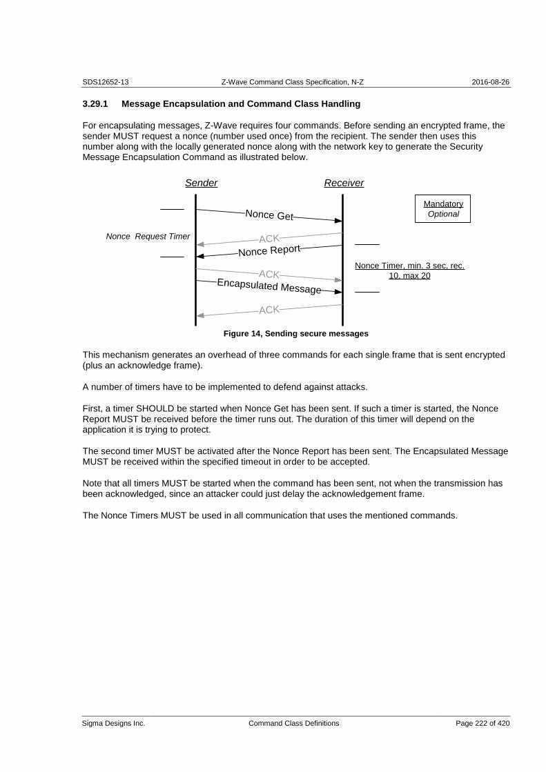
SDS12652-13 Z-Wave Command Class Specification, N-Z 2016-08-26
Sigma Designs Inc. Command Class Definitions Page 222 of 420
3.29.1 Message Encapsulation and Command Class Handling
For encapsulating messages, Z-Wave requires four commands. Before sending an encrypted frame, the sender MUST request a nonce (number used once) from the recipient. The sender then uses this number along with the locally generated nonce along with the network key to generate the Security Message Encapsulation Command as illustrated below.
Sender Receiver
Nonce Get
ACK
Nonce Report
ACKEncapsulated Message
ACK
Nonce Request Timer
Mandatory
Optional
Nonce Timer, min. 3 sec, rec.
10, max 20
Figure 14, Sending secure messages
This mechanism generates an overhead of three commands for each single frame that is sent encrypted (plus an acknowledge frame).
A number of timers have to be implemented to defend against attacks.
First, a timer SHOULD be started when Nonce Get has been sent. If such a timer is started, the Nonce Report MUST be received before the timer runs out. The duration of this timer will depend on the application it is trying to protect.
The second timer MUST be activated after the Nonce Report has been sent. The Encapsulated Message MUST be received within the specified timeout in order to be accepted.
Note that all timers MUST be started when the command has been sent, not when the transmission has been acknowledged, since an attacker could just delay the acknowledgement frame.
The Nonce Timers MUST be used in all communication that uses the mentioned commands.

SDS12652-13 Z-Wave Command Class Specification, N-Z 2016-08-26
Sigma Designs Inc. Command Class Definitions Page 223 of 420
In order to optimize the performance the device MUST use streaming when transmitting multiple frames. The overhead using this option will then converge towards two (instead of three) transmissions as the number of frames increases.
Nonce Get
ACK
Nonce Report
ACKEnc. Msg. Nonce Get
ACK
ACK
Nonce Request Timer
Nonce Timer, min. 3 sec, rec.
10, max 20
Sender Receiver
Nonce Report
Enc. Msg. Nonce Get
ACK
Nonce Request Timer
Nonce Timer, min. 3 sec, rec.
10, max 20
Mandatory
Optional
Figure 15, Streaming secure messages
Notice: The maximum command size is reduced by 20 bytes due to the security overhead. Larger commands can use sequencing as described in 3.29.1.3.
3.29.1.1 Nonce Challenge Request Command
This command is used to request an external nonce from the receiving node.
Note that a nonce will only be valid for one attempt. The nonce is discarded when the receiver has used it for decrypting the command. A new nonce MUST be exchanged for each new command.
The Nonce Challenge Response Command MUST be returned in response to this command.
This command MUST NOT be issued via multicast addressing. A receiving node MUST NOT return a response if this command is received via multicast addressing. The Z-Wave Multicast frame, the broadcast NodeID and the Multi Channel multi-End Point destination are all considered multicast addressing methods.
7 6 5 4 3 2 1 0
Command Class = COMMAND_CLASS_SECURITY
Security Header = SECURITY_NONCE_GET

SDS12652-13 Z-Wave Command Class Specification, N-Z 2016-08-26
Sigma Designs Inc. Command Class Definitions Page 224 of 420
3.29.1.2 Nonce Challenge Response Command
The device uses the Security Nonce Report Command to return the next nonce to the requesting node.
7 6 5 4 3 2 1 0
Command Class = COMMAND_CLASS_SECURITY
Security Header = SECURITY_NONCE_REPORT
Nonce byte 1
Nonce byte 2
Nonce byte 3
Nonce byte 4
Nonce byte 5
Nonce byte 6
Nonce byte 7
Nonce byte 8
Nonce byte (8 bytes)
This field contains the 8 bytes external nonce used for encryption.
3.29.1.3 Security Message Encapsulation Command
The device uses the Security Message Encapsulation command to encapsulate Z-Wave commands using AES-128.
The device will also request a new external nonce from the receiver when transmitting the message Security Message Encapsulation Nonce Get. The device uses the external nonce when streaming multiple secure messages without having to call Nonce Get after receiving each message as shown in Figure 15, Streaming secure messages.
A device MUST ignore the received Security Message Encapsulation command if the generated Nonce has timed out.

SDS12652-13 Z-Wave Command Class Specification, N-Z 2016-08-26
Sigma Designs Inc. Command Class Definitions Page 225 of 420
7 6 5 4 3 2 1 0
Command Class = COMMAND_CLASS_SECURITY
Security Header = SECURITY_MESSAGE_ENCAPSULATION (_NONCE_GET)
Initialization Vector byte 1
Initialization Vector byte 2
Initialization Vector byte 3
Initialization Vector byte 4
Initialization Vector byte 5
Initialization Vector byte 6
Initialization Vector byte 7
Initialization Vector byte 8
Reserved Second Frame
Sequenced Sequence Counter
(Command Class identifier)
(Command identifier)
Command byte 1
..
Command byte N
Receiver’s nonce Identifier
Message Authentication Code byte 1
Message Authentication Code byte 2
Message Authentication Code byte 3
Message Authentication Code byte 4
Message Authentication Code byte 5
Message Authentication Code byte 6
Message Authentication Code byte 7
Message Authentication Code byte 8
Initialization Vector byte (8 byte)
The initialization vector is the internal nonce generated by the sender. The payload is encrypted with the external and internal nonce concatenated together.
Reserved
This field MUST be set to 0 by a sending node and MUST be ignored by a receiving node.

SDS12652-13 Z-Wave Command Class Specification, N-Z 2016-08-26
Sigma Designs Inc. Command Class Definitions Page 226 of 420
Sender Receiver
Security Nonce Get
Security Nonce Report
Security Message Encapsulation Nonce Get
Command Class
Command Id
Payload 1
.
.
.
N
Security Nonce Report
Security Message Encapsulation
Figure 16, Frame flow for sequenced frames
Sequenced (1 bit)
This flag MUST be set if the command is transmitted using multiple frames. This flag MUST not set if the command is contained entirely in a single (this) frame. As shown in figure, the first frame in a sequence MUST be sent using Security Message Encapsulation Nonce Get. To minimize overhead, following frames SHOULD be sent using the Security Message Encapsulation Nonce Get command. The last frame MAY be sent using Security Message Encapsulation.
Notice that device only lists Command class identifier and command identifier in the first frame.
Second Frame (1 bit)
If this flag and the Sequenced flag are set, the frame is the second out of two. If the flag is not set, and Sequenced flag is set, it is the first frame out of two. Valid combinations are:
Table 87, Security message encapsulation::Second Frame combinations
Sequenced 1 Sequenced 0
Second Frame 1 Second frame of two -
Second Frame 0 First frame of two Single Frame

SDS12652-13 Z-Wave Command Class Specification, N-Z 2016-08-26
Sigma Designs Inc. Command Class Definitions Page 227 of 420
Sequence Counter (4 bits)
If Sequenced flag is set, the frame is one out of two. In order to tell multiple sequences apart, they MUST be uniquely identified based on the sender NodeID and the Sequence Counter. For each sequenced set of frames a node sends it MUST increment the Sequence Counter by one.
Command Class Identifier (8 bits) (Part of Encrypted Payload)
This field contains the identifier of the Command class, which the device sends to the NodeID.
Command identifier (8 bits) (Part of Encrypted Payload)
This field contains the identifier of the Command, which the device sends to the NodeID.
Command byte (N bytes) (Part of Encrypted Payload)
These fields contain the parameters, which the device sends to the NodeID.
Receiver’s nonce Identifier (8 bits)
Identifies nonce being used.
Message Authentication Code byte (8 bytes)
Data used for authenticating the received message to prevent tampering.

SDS12652-13 Z-Wave Command Class Specification, N-Z 2016-08-26
Sigma Designs Inc. Command Class Definitions Page 228 of 420
3.29.2 Network Key Management
The same network key is used by all secure nodes in the network. Distribution of network keys uses a temporary key to protect the key exchange. Exchange of network key happens immediately after successful inclusion of the node. It requires a secure primary/inclusion controller to include a secure node into the secure network as secure.
3.29.2.1 Network Inclusion
The first step of including a node to a secure network is using the standard Z-Wave inclusion process. If both the new node and the inclusion controller support Security command class, the controller will subsequently send the network key to the newly included node.
Including Controller Included Node
Scheme Get
Inclusion Completed
ACK
Scheme Report
ACKNonce Get
ACK
Nonce Report
ACKEnc. Msg. (Key Set)
ACK
Nonce Get
ACKNonce Report
ACK
Enc. Msg. (Key Verify)
Inclusion Timer - 10 sec
Inclusion Timer - 10 sec
Nonce Timer, min. 3 sec, rec.
10, max 20
Nonce Request Timer
Nonce Request Timer
Mandatory
Optional
Nonce Timer, min. 3 sec, rec.
10, max 20
If Network Key Verify fails or the timeout is reached, Trust Center
informs installer and the node must be excluded and included
using same process again. If the process is not attemped again
the included node will not be part of the secure network but will be
present in the network as a non-secure node. The node may
communicate with other non-secure nodes in the network
After Inclusion – If
ControllerSecurity Scheme Inherit
Security Scheme Report
Message encapsulated using Security
Message Encapsulation, hence it will be
preceeded with a nonce request and report
Message is sent unencrypted
Figure 17, Inclusion into a secure network

SDS12652-13 Z-Wave Command Class Specification, N-Z 2016-08-26
Sigma Designs Inc. Command Class Definitions Page 229 of 420
The Trust Center in Figure 17 refers to the including controller, and the installer is the user (or technician) operating the including controller.
To protect the security of a secure network, all controllers SHOULD require a PIN to unlock the security inclusion process and slaves SHOULD require a PIN to accept being included and excluded.
Following the inclusion of the node into the network, the controller will request the security scheme supported by the included node. Battery operated devices SHOULD stay awake for the duration of the setup of the Security Command class.
Currently one security scheme exist which is extendable at a later stage:
1. Security 0/N: 0x00 repeated 16 times as temporary key for encrypting the network key when it is transferred using normal power.
The validity of the key is verified in both the added node and the including controller. The node verifies the key based on the Message Authentication Code and then transmits an encrypted Network Key Verify command as response to the controller. When a device supporting the Security Command class does not manage to enter the secure network, it will function as a non-secure device. The node requires exclusion from the network before another attempt comprising of inclusion and network key exchange is possible.
For the currently available Security 0/N scheme, the same network key is used by all nodes in the network.
For the including controller to allow inclusion of a Secure device into the secure network, a common security scheme needs to be supported by both devices. When supporting multiple common schemes the highest possible scheme MUST be used. If no common schemes are supported the device MUST NOT be included into the network.
When nodes in the secure network wish to establish a connection to a device that supports the Security Command class, they MUST send the Security Command Supported Get command to the device. Receiving no Security Command Supported Report (since the recipient does not have the key to decrypt the request), it will not be able to talk to the device securely. The same applies for the situation where a secure device does not become part of the secure network because it was included by a non-secure controller.
A slave device MUST NOT consider a secure inclusion successful until the Network Key Set has been received. A controller device MUST NOT consider the secure inclusion successful until the Security Scheme inherit has been received.

SDS12652-13 Z-Wave Command Class Specification, N-Z 2016-08-26
Sigma Designs Inc. Command Class Definitions Page 230 of 420
3.29.2.1.1 Inclusion through Non-Secure Inclusion controller
A Security-enabled SIS MAY perform secure setup after inclusion from a non-secure inclusion controller. As soon as the Security enabled SIS (hereafter SIS), receives information from the non-secure inclusion controller that a node with support for the Security command class has been included, the SIS MAY start the secure setup process of sending the network key to the newly included node as illustrated in Figure 18. At this stage the SIS acts as if it, itself had performed the inclusion and MAY carry out all the steps REQUIRED for secure setup, included making sure the timeouts are not exceeded.
Before starting the Secure inclusion process, the SIS MUST be put into a state that allows it to carry out the secure setup for 1 node for the next 3 minutes and no longer. The SIS MUST be put in this state through a password-protected menu to avoid unintentional reveal of the network key by a fake controller.
It should be noted that performing the secure setup on behalf of a non-secure inclusion controller might add to the complexity of the actions required by the user, and thus make it easier for a hacker to perform social engineering to circumvent the security so care must be taken to inform the user accordingly.
Non-Secure Inclusion
ControllerIncluded Node
Scheme Get
Inclusion Completed
Etc.
Included Node ID X
...
Secure SIS
Secure Activation (3mins max)
Figure 18, Secure Inclusion through Non-Secure Inclusion Controller

SDS12652-13 Z-Wave Command Class Specification, N-Z 2016-08-26
Sigma Designs Inc. Command Class Definitions Page 231 of 420
3.29.2.1.2 Inclusion Timers
As shown in Figure 17, a number of timeout MUST be complied with. For the including controller see Figure 19.
Including Node
Inclusion
CompleteScheme Report Nonce Report Key Verify
Security
Scheme ReportIf Controller
Terminate
Secure
Inclusion
Timer Exceeded
Timer Exceeded Timer Exceeded Timer Exceeded / Invalid Verify
Timer Exceeded
Secure
Inclusion
Complete
If Slave
10 sec max 10 sec max 10 sec max 10 sec max
10 sec max
10 sec max
Figure 19, Timers on Including Controller
For the new included node, the timers in Figure 20 MUST be complied with.
Included Node
Inclusion
CompleteScheme Get Nonce Get Key Set
Security
Scheme InheritIf Controller
Terminate
Secure
Inclusion
Timer Exceeded
Timer Exceeded Timer Exceeded Timer Exceeded / Invalid Verify
Timer Exceeded
Secure
Inclusion
Complete
If Slave
10 sec max 10 sec max 10 sec max 10 sec max
10 sec max
10 sec max
Figure 20, Timers on newly Included Node
The Network Key MUST NOT be sent to the new node if a Security Scheme Report command is received by the including controller later than 10 seconds after successful inclusion of the node. The controller SHOULD notify the user of an error condition in case of timeout because the device functions only as non-secure. In addition, the included node MUST NOT accept and respond to a Scheme Get it is received later than 10 seconds after successful inclusion. When a valid frame is received before the timeout, the timeout is extended to allow the next part of the inclusion process. The inclusion process MUST be terminated if any message times out.

SDS12652-13 Z-Wave Command Class Specification, N-Z 2016-08-26
Sigma Designs Inc. Command Class Definitions Page 232 of 420
3.29.2.2 Security Scheme Get Command
A controlling device MUST send Security Scheme Get Command immediately after the successful inclusion of a node that supports the Security Command class.
A node is considered newly included if it has been included for less than 10 seconds.
A newly included node MUST return the Security Scheme Report Command in response to this command.
Whether a node has been included securely or non-securely, the node MUST NOT respond to the Security Scheme Get command if it is not newly included.
This command MUST NOT be issued via multicast addressing. A receiving node MUST NOT return a response if this command is received via multicast addressing. The Z-Wave Multicast frame, the broadcast NodeID and the Multi Channel multi-End Point destination are all considered multicast addressing methods.
7 6 5 4 3 2 1 0
Command Class = COMMAND_CLASS_SECURITY
Command = SECURITY_SCHEME_GET
Supported Security Schemes
Supported Security Schemes (8 bits)
The Security Schemes which are supported by the primary/inclusion controller. At least one security scheme MUST be supported. Values MUST comply withTable 88.
Table 88, Security Scheme Get::Supported Security Schemes encoding
Bit Supports
0 Security 0 using normal power = 0
Bit 0 MUST always be set to 0, indicating support for Security 0. All other bits are reserved and MUST be set to zero by a sending node. Reserved bits MUST be ignored by a receiving node.

SDS12652-13 Z-Wave Command Class Specification, N-Z 2016-08-26
Sigma Designs Inc. Command Class Definitions Page 233 of 420
3.29.2.3 Security Scheme Report Command
This command is used to advertise security scheme 0 support by the node being included. Upon reception, the including controller MUST send the network key immediately without waiting for input, by using 16 times 0x00 as the temporary key. The including controller MUST NOT perform any validation of the Supported Security Schemes byte.
7 6 5 4 3 2 1 0
Command Class = COMMAND_CLASS_SECURITY
Command = SECURITY_SCHEME_REPORT
Supported Security Schemes
Supported Security Schemes (8 bits)
See Security Scheme Get for a definition.
3.29.2.4 Network Key Set Command
The Device can use the Network Key Set Command to set the network key in a Z-Wave node. Transmission of the Network Key Set command requires existence of a common agreed security scheme. The device uses the agreed temporary key to encapsulate the Network Key Set command. The included node MUST handle the Network Key Set command according to the guidelines in section 3.29.2.
This command MUST be sent encapsulated by the Security Message Encapsulation command.
7 6 5 4 3 2 1 0
Command Class = COMMAND_CLASS_SECURITY
Command = NETWORK_KEY_SET
Network Key byte 1
..
Network Key byte N
Network Key byte (N bytes)
The Network key to exchange application data secure in the network.

SDS12652-13 Z-Wave Command Class Specification, N-Z 2016-08-26
Sigma Designs Inc. Command Class Definitions Page 234 of 420
3.29.2.5 Network Key Verify Command
When the included node has received a Network Key Set that is has successfully decrypted, verified by the MAC, it MUST send a Network Key Verify Command to the including controller. If the controller is capable of decrypting the Network Key Verify command it would indicate that the included node has successfully entered the secure network. Since there is no timeout for the Network Key Verify, the controller can send a Security Commands Supported Get command, and if no response is received, it SHOULD be concluded that the node has not been included properly.
This command MUST be sent encapsulated by the Security Message Encapsulation command.
7 6 5 4 3 2 1 0
Command Class = COMMAND_CLASS_SECURITY
Command = NETWORK_KEY_VERIFY
3.29.2.6 Security Scheme Inherit Command
When a controller is included to the network, it MUST inherit the same security scheme as the including controller allowing it to become an inclusion controller. This is achieved through the Security Scheme Inherit Command, which is sent when the network key has successfully been setup, as shown in Figure 17.
When including a controller into the secure network, the new controller MUST inherit any common supported security schemes. For example, if the new controller supports security scheme bit 1 and bit 4 but the including controller only supports security scheme bit 1, the new controller MUST after inclusion also only support security scheme bit 1.
This command MUST be sent encapsulated by the Security Message Encapsulation command.
7 6 5 4 3 2 1 0
Command Class = COMMAND_CLASS_SECURITY
Command = SECURITY_SCHEME_INHERIT
Supported Security Schemes
Supported Security Schemes (8 bits)
See Security Scheme Get command, for a definition.
To ensure that the included controller has inherited the correct security scheme, it MUST respond with a Security Scheme Report command as illustrated in Figure 17. If the reported security scheme does not match, the installer MUST be notified that the included controller is violating the security scheme, and the node SHOULD be excluded again as an error situation has occurred.

SDS12652-13 Z-Wave Command Class Specification, N-Z 2016-08-26
Sigma Designs Inc. Command Class Definitions Page 235 of 420
3.29.3 Encapsulated Command Class Handling
The Node Info Frame is only used to advertise all the command classes that are supported non-securely. Command classes supported securely MUST be advertised by using the Security Commands Supported Get/Report.
All non-securely supported command classes MUST also be supported securely.
All non-securely controlled command classes MUST also be controlled securely.
All non-securely supported command classes MAY be explicitly advertised in the Security Commands Supported Report.
To make a security enabled device compatible with non-secure applications a secure node MAY choose to report support for some command classes non-secure in the Node Info Frame, as well as in the Security Command Supported Report. Initially, the Node Info Frame MUST advertise all non-securely supported command classes , while the Node Info Frame MAY advertise non-securely controlled command classes. If the node is included into a secure network, it MAY choose to remove all or some command classes from the Node Info Frame, and thus only support them securely – removing support for the command classes for all non-secure nodes.
If the node is included into a non-secure network, it MAY choose to support command classes it would not support non-securely if it had been included into a secure network.
An example of this could be a relay as shown in Table 89.
Table 89, Command Class support depending on inclusion (example)
Before Inclusion Included Non-Secure
Included Secure
Security Command Supported Report Frame
-N/A -N/A
Binary Switch
Version
Node Info Frame Security
Binary Switch
Version
Binary Switch
Version
Security
It is up to the implementation of each application to decide which commands should be supported using security encapsulation and non-secure.
If a command class is only supported securely it MUST NOT be listed in the node info frame, while it MUST be advertised in the security commands supported report frame.
The Basic Command Class MUST NOT be advertised in the Security Commands Supported Report.
The Node Info Frame MUST advertise the security Command Class before inclusion. The Node Info Frame MUST advertise the security Command Class after secure inclusion. The Node Info Frame SHOULD NOT advertise the security Command Class after non-secure inclusion

SDS12652-13 Z-Wave Command Class Specification, N-Z 2016-08-26
Sigma Designs Inc. Command Class Definitions Page 236 of 420
The Node Info Frame MUST NOT advertise the Version Command Class and the Manufacturer Specific Command Class after secure inclusion.Precautions should be taken when setting up the network, since the order of inclusion may change the supported functionality of the devices. For example if a non-secure controller included the above relay it would be able to operate it, but if included using a secure controller, only the version request would be possible non-securely.
In a secure network, initially only the including controller will have any knowledge about what nodes in the network have been setup securely. If a node wishes to talk to another node it MAY send a Security Command Supported Get command encapsulated to the other node. If a Security Commands Supported Report is returned the node is in possession of a valid network key, and is part of the secure network. This mechanism may also be used by the including controller to ensure that the node has been included properly.
3.29.3.1 Multi Channel Handling
Any device that supports the Security and Multi Channel Command Classes MAY choose to support a different set of Command Classes securely for each Multi Channel End Point. An End Point with support for Security MUST report the Security Command Class as supported for that End Point. The command classes supported for each endpoint securely is determined by using the Security Commands Supported Get command sent to each individual endpoint Security Encapsulated. Hence, the encapsulation order is: Security Encapsulation – Multi Channel Encapsulation – Security Commands Supported Get Command
When communicating with a device that supports multiple Multi Channel End Points, the Security Encapsulation MUST be added outside of the Multi Channel Command Class. Thus, a receiving node MUST first remove the Security Encapsulation and then forward it to the actual destination Multi Channel End Point.
A Multi Channel End Point MUST be considered as a separate device, with separate NIF – given by Multi Channel Capability Report and Security Commands Supported Report.
Multi Channel End Points are logical abstractions. Only the Root Device is included in the network.
This means:
Inclusion always deals with the Root Device.
A Security Command Support Get must reply as a Root Device. If the Multi Channel Command Class is not supported non-securely, it will only be listed in the Security Command Supported Report.
The Multi Channel Capability Report MUST advertise the Security Command Class as supported for all End Points that implement command classes that are supported securely.
The implicit rule that all non-secure command classes for an End Point must be controllable securely is still in effect, if the endpoint is reported secure.
An End Point only inherits the security capabilities of the End Point itself. I.e. each End Point is considered a device itself.

SDS12652-13 Z-Wave Command Class Specification, N-Z 2016-08-26
Sigma Designs Inc. Command Class Definitions Page 237 of 420
3.29.3.2 Security Commands Supported Get Command
This command is used to query the commands supported by the device when using secure communication.
The Security Commands Supported Report Command MUST be returned in response to this command.
A node MAY choose only to advertise a Command Class as ‘supported’ and/or ‘controlled’, when secure communication is used. In that case the Command Class MUST NOT be advertised in the NIF, while it MUST be advertised in the Security Commands Supported Report Command.
Secure communication MUST be used when transmitting this command.
This command MUST NOT be issued via multicast addressing. A receiving node MUST NOT return a response if this command is received via multicast addressing. The Z-Wave Multicast frame, the broadcast NodeID and the Multi Channel multi-End Point destination are all considered multicast addressing methods.
7 6 5 4 3 2 1 0
Command Class = COMMAND_CLASS_SECURITY
Command = SECURITY_COMMANDS_SUPPORTED_GET
3.29.3.3 Security Commands Supported Report Command
This command advertises which command classes are supported using security encapsulation..
All non-securely supported command classes MAY be explicitly advertised in the Security Commands Supported Report.
All securely supported command classes MUST be explicitly advertised in the Security Commands Supported Report if they are only supported securely.
Secure communication MUST be used when transmitting this command.
7 6 5 4 3 2 1 0
Command Class = COMMAND_CLASS_SECURITY
Command = SECURITY_COMMANDS_SUPPORTED_REPORT
Reports to follow
Command Class (0x20 – 0xEE) 1 (support)
…
Command Class (0x20 – 0xEE) N (support)
COMMAND_CLASS_MARK
Command Class (0x20 – 0xEE) 1 (control)
…
Command Class (0x20 – 0xEE) K (control)

SDS12652-13 Z-Wave Command Class Specification, N-Z 2016-08-26
Sigma Designs Inc. Command Class Definitions Page 238 of 420
To support extended command classes use the following format. Note that these MAY be mixed.
This command MUST only be send encapsulated by the Security Message Encapsulation command.
7 6 5 4 3 2 1 0
Command Class = COMMAND_CLASS_SECURITY
Command = SECURITY_COMMANDS_SUPPORTED_REPORT
Reports to follow
Command Class MSB (0xF1 – 0xFF) 1
Command Class LSB (0x00 – 0xFF) 1
…
Command Class MSB (0xF1 – 0xFF) N
Command Class LSB (0x00 – 0xFF) N
COMMAND_CLASS_MARK
Command Class MSB (0xF1 – 0xFF) 1
Command Class LSB (0x00 – 0xFF) 1
…
Command Class MSB (0xF1 – 0xFF) K
Command Class LSB (0x00 – 0xFF) K
Reports to follow (8 bits)
This value indicates how many report frames left before transferring the entire list of command classes.
Command Class (N * 8 bits)
The command class identifier.
Command Class Mark (8 bits)
The COMMAND_CLASS_MARK is used to indicate that all preceding command classes are supported, and all following command classes are controlled.
3.30 Sensor Configuration Command Class, version 1 [OBSOLETED]
THIS COMMAND CLASS HAS BEEN OBSOLETED
New implementations MUST NOT use the Sensor Configuration Command Class. Please refer to the
Configuration Command Classes.

SDS12652-13 Z-Wave Command Class Specification, N-Z 2016-08-26
Sigma Designs Inc. Command Class Definitions Page 239 of 420
The Sensor Configuration Command Class adds the possibility for sensors to act on either a measured value or on a preconfigured value. With this command class an application can act on a specific event. It is up to the application to implement the actual event. This could e.g. be implementation of the Association Command Class where the application would activate a group based on a trigger from the sensor.
The trigger types that may be configured are the same types as the values specified in the Multilevel Sensor Command Class
Most movement sensors may be configured to "ignore" movement if it is not dark. Typically this is done manually. With the Sensor Configuration Command Class this may be configured remotely in a standardised way.
A device supporting the Sensor Configuration Command Class may be configured via the trigger level, but the decision on what the level change should trigger is up to the application. For the movement sensor this trigger level could be an input parameter to the logic that controls the light.
3.30.1 Sensor Trigger Level Set Command
The Sensor Trigger Level Set Command may be used to set different triggers to either a specified value or to the current measured value. The Command also supports to restore a factory default value.
All configurable trigger types and values MUST be mapped direct from the Multilevel Sensor Command Class.
It is RECOMMENDED that all combinations of precision, scale and size parameters are supported. The Set command MUST support same format of precision, scale and size parameters as can be returned in the report command.
7 6 5 4 3 2 1 0
Command Class = COMMAND_CLASS_SENSOR_CONFIGURATION
Command = SENSOR_TRIGGER_LEVEL_SET
Default Current Reserved
Sensor Type
Precision Scale Size
Trigger Value
…
Default (1 bit)
Reset level of trigger type to factory default when this bit is set to 1. If any value is set in this frame when the Default bit is 1 this value will be ignored.
Current (1 bit)
The current measured value will be stored as trigger value when this bit is set to 1. The trigger value in this frame will be ignored when the Current bit is set to 1.
Reserved

SDS12652-13 Z-Wave Command Class Specification, N-Z 2016-08-26
Sigma Designs Inc. Command Class Definitions Page 240 of 420
This field MUST be set to 0 by a sending node and MUST be ignored by a receiving node.
Precision (3 bits)
The precision field describes what the precision of the trigger value is. The number indicates the number of decimals. The decimal value 1025 with precision 2 is therefore equal to 10.25. Scale (2 bits)
The Scale used to indicate what unit the trigger uses. Refer to the table in the Multilevel Sensor Command Class with respect to defined scales for the relevant triggers. Scales are defined by the Z-Wave Alliance. Size (3 bits)
The size field indicates the number of bytes used for the trigger value. This field can take values from 1 (001b), 2 (010b) or 4 (100b). Sensor Type (8 bits)
The Sensor Type specifies what type of trigger this Command will set. Refer to the Multilevel Sensor Command Class specification, where Sensor Type is defined in the Multilevel Sensor Report Command.
Trigger Value
Refer to the Multilevel Sensor Report Command for information on what trigger values to set.
3.30.2 Sensor Trigger Level Get Command
The Sensor Trigger Level Get Command can request the stored trigger level.
The Sensor Trigger Level Report Command MUST be returned in response to this command.
This command MUST NOT be issued via multicast addressing. A receiving node MUST NOT return a response if this command is received via multicast addressing. The Z-Wave Multicast frame, the broadcast NodeID and the Multi Channel multi-End Point destination are all considered multicast addressing methods.
7 6 5 4 3 2 1 0
Command Class = COMMAND_CLASS_SENSOR_CONFIGURATION
Command = SENSOR_TRIGGER_LEVEL_GET

SDS12652-13 Z-Wave Command Class Specification, N-Z 2016-08-26
Sigma Designs Inc. Command Class Definitions Page 241 of 420
3.30.3 Sensor Trigger Level Report Command
The Sensor Trigger Level Report Command returns the stored trigger value.
7 6 5 4 3 2 1 0
Command Class = COMMAND_CLASS_SENSOR_CONFIGURATION
Command = SENSOR_TRIGGER_LEVEL_REPORT
Sensor Type
Precision Scale Size
Trigger Value
…
Sensor Type (8 bits)
Refer to the Sensor Trigger Level Set Command Class.
Precision (3 bits)
Refer to the Sensor Trigger Level Set Command Class.
Scale (2 bits)
Refer to the Sensor Trigger Level Set Command Class.
Size (3 bits)
Refer to the Sensor Trigger Level Set Command Class.
Trigger Value
Refer to the Sensor Trigger Level Set Command Class.

SDS12652-13 Z-Wave Command Class Specification, N-Z 2016-08-26
Sigma Designs Inc. Command Class Definitions Page 242 of 420
3.30.4 Mapping example
The report structure of the Multilevel Sensor Command Class can be mapped direct into the Sensor Configuration Set Command Class. This example frame below will set the trigger level in the receiving node to 10.25 degree Celsius.
7 6 5 4 3 2 1 0
Command Class = COMMAND_CLASS_SENSOR_CONFIGURATION
Command = SENSOR_TRIGGER_LEVEL_SET
Default(0) Current(0) Reserved
Temperature (0x01)
Precision (010b) Celsius (00b) Size (010b)
0x04
0x01

SDS12652-13 Z-Wave Command Class Specification, N-Z 2016-08-26
Sigma Designs Inc. Command Class Definitions Page 243 of 420
3.31 Simple AV Control Command Class, version 1-4
The Simple AV Control Command Class is used to control an AV device in a Z-Wave network. The Simple AV Control Command Class is suited for IR remote replacement. Furthermore, this command class supports Windows Vista Media Center and Media Center 2005 remote controls.
3.31.1 Simple AV Control Set Command
The Simple AV Control Set Command is used to control an AV device.
7 6 5 4 3 2 1 0
Command Class = COMMAND_CLASS_SIMPLE_AV_CONTROL
Command = SIMPLE_AV_CONTROL_SET
Sequence Number
Reserved Key Attributes
Item ID MSB
Item ID LSB
Command MSB,1
Command LSB,1
…
Command MSB,N
Command LSB,N

SDS12652-13 Z-Wave Command Class Specification, N-Z 2016-08-26
Sigma Designs Inc. Command Class Definitions Page 244 of 420
Sequence Number (8 bits)
The sequence number is incremented each time a Simple AV Control Set Command is issued. The receiving node uses the sequence number to ignore duplicates.
Key Attributes (3 bits)
The key attributes specifies the state of the key. Currently the following key attribute definitions exist:
Table 90, Simple AV Control Set::Key Attributes encoding
Key Attribute Description
0x00 Key Down – Sent when a new key is pressed. It is mandatory to send a Simple AV Control Set Command when this event occurs.
0x01 Key Up – Sent when the key is released. It is optional to send a Simple AV Control Set Command when this event occurs. Only the sequence number and key attribute parameter is changed in the Command.
0x02 Keep Alive – Sent every 100-200ms while the key is still held down. Event used as a failsafe feature for the ramping function, e.g. avoid volume jumps to maximum in case a key up event is not received. The keep alive event can also be used to control the speed of the ramping function, e.g. the first few seconds of the key held down is the speed slow and afterwards will it gradually accelerate. It is optional to send a Simple AV Control Set Command when this event occurs. Only the sequence number and key attribute parameter is changed in the Command.
All other values are reserved and MUST NOT be used by a sending node. Reserved values MUST be ignored by a receiving node.
Un-supported key attribute values MUST be ignored.
Reserved
This field MUST be set to 0 by a sending node and MUST be ignored by a receiving node.
Item ID (16 bits)
The ID of the media item the Command relates to. No media item is selected in case ID is equal to 0.
Command MSB, Command LSB (N * 16 bits)
A 2 byte AV control Command according to the table below. It is possible to send a sequence of Commands in one frame. If an AV control command is not supported, it MUST be ignored. Device related labels are not sent but only used internally in the remote to set up the appropriate address. The address MAY be a NodeID. Command number 1 through 40 is the most popular Commands used in remotes. Command number 41 through 363 is less popular and is sorted in alphanumerical order. Finally is support for Windows Vista Media Center and Media Center 2005 remote controls added from 364 to 377 including 16, 200 and 231.

SDS12652-13 Z-Wave Command Class Specification, N-Z 2016-08-26
Sigma Designs Inc. Command Class Definitions Page 245 of 420
Table 91, Simple AV Control codes and associated label
Command #
[Decimal]
Command #
[Hexadecimal]
Universal Label Description
1 0x0001 Mute
2 0x0002 Volume Down Level Down
3 0x0003 Volume Up Level Up
4 0x0004 Channel Up Program Up
5 0x0005 Channel Down Program Down
6 0x0006 0 Preset 10
7 0x0007 1 Preset 1
8 0x0008 2 Preset 2
9 0x0009 3 Preset 3
10 0x000A 4 Preset 4
11 0x000B 5 Preset 5
12 0x000C 6 Preset 6
13 0x000D 7 Preset 7
14 0x000E 8 Preset 8
15 0x000F 9 Preset 9
16 0x0010 Last Channel Recall, Previous Channel (WMC)
17 0x0011 Display Info
18 0x0012 Favorite Channel Favorite
19 0x0013 Play
20 0x0014 Stop
21 0x0015 Pause Still
22 0x0016 Fast Forward Search Forward
23 0x0017 Rewind Search Reverse
24 0x0018 Instant Replay Replay
25 0x0019 Record
26 0x001A AC3 Dolby Digital
27 0x001B PVR Menu Tivo
28 0x001C Guide EPG
29 0x001D Menu Settings
30 0x001E Menu Up Adjust Up
31 0x001F Menu Down Adjust Down
32 0x0020 Menu Left Cursor Left
33 0x0021 Menu Right Cursor Right
34 0x0022 Page Up
35 0x0023 Page Down
36 0x0024 Select OK
37 0x0025 Exit
38 0x0026 Input Input Select
39 0x0027 Power Standby
40 0x0028 Enter Channel Channel Enter
41 0x0029 10
42 0x002A 11
43 0x002B 12

SDS12652-13 Z-Wave Command Class Specification, N-Z 2016-08-26
Sigma Designs Inc. Command Class Definitions Page 246 of 420
Command #
[Decimal]
Command #
[Hexadecimal]
Universal Label Description
44 0x002C 13
45 0x002D 14
46 0x002E 15
47 0x002F 16
48 0x0030 +10 10+
49 0x0031 +20 20+
50 0x0032 +100
51 0x0033 -/--
52 0x0034 3-CH
53 0x0035 3D Simulated Stereo
54 0x0036 6-CH Input 6 Channel
55 0x0037 A
56 0x0038 Add Write
57 0x0039 Alarm
58 0x003A AM
59 0x003B Analog
60 0x003C Angle
61 0x003D Antenna External
62 0x003E Antenna East
63 0x003F Antenna West
64 0x0040 Aspect Size
65 0x0041 Audio 1 Audio
66 0x0042 Audio 2
67 0x0043 Audio 3
68 0x0044 Audio Dubbing
69 0x0045 Audio Level Down
70 0x0046 Audio Level Up
71 0x0047 Auto/Manual
72 0x0048 Aux 1 Aux
73 0x0049 Aux 2
74 0x004A B
75 0x004B Back Previous Screen
76 0x004C Background Backlight
77 0x004D Balance
78 0x004E Balance Left
79 0x004F Balance Right
80 0x0050 Band FM/AM
81 0x0051 Bandwidth Wide/Narrow
82 0x0052 Bass
83 0x0053 Bass Down
84 0x0054 Bass Up
85 0x0055 Blank
86 0x0056 Breeze Mode
87 0x0057 Bright Brighten

SDS12652-13 Z-Wave Command Class Specification, N-Z 2016-08-26
Sigma Designs Inc. Command Class Definitions Page 247 of 420
Command #
[Decimal]
Command #
[Hexadecimal]
Universal Label Description
88 0x0058 Brightness
89 0x0059 Brightness Down
90 0x005A Brightness Up
91 0x005B Buy
92 0x005C C
93 0x005D Camera
94 0x005E Category Down
95 0x005F Category Up
96 0x0060 Center
97 0x0061 Center Down Center Volume Down
98 0x0062 Center Mode
99 0x0063 Center Up Center Volume Up
100 0x0064 Channel/Program C/P
101 0x0065 Clear Cancel
102 0x0066 Close
103 0x0067 Closed Caption CC
104 0x0068 Cold A/C
105 0x0069 Color
106 0x006A Color Down
107 0x006B Color Up
108 0x006C Component 1 RGB 1
109 0x006D Component 2 RGB 2
110 0x006E Component 3
111 0x006F Concert
112 0x0070 Confirm Check
113 0x0071 Continue Continuous
114 0x0072 Contrast
115 0x0073 Contrast Down
116 0x0074 Contrast Up
117 0x0075 Counter
118 0x0076 Counter Reset
119 0x0077 D
120 0x0078 Day Down
121 0x0079 Day Up
122 0x007A Delay
123 0x007B Delay Down
124 0x007C Delay Up
125 0x007D Delete Erase
126 0x007E Delimiter Sub-Channel
127 0x007F Digest
128 0x0080 Digital
129 0x0081 Dim Dimmer
130 0x0082 Direct
131 0x0083 Disarm

SDS12652-13 Z-Wave Command Class Specification, N-Z 2016-08-26
Sigma Designs Inc. Command Class Definitions Page 248 of 420
Command #
[Decimal]
Command #
[Hexadecimal]
Universal Label Description
132 0x0084 Disc
133 0x0085 Disc 1
134 0x0086 Disc 2
135 0x0087 Disc 3
136 0x0088 Disc 4
137 0x0089 Disc 5
138 0x008A Disc 6
139 0x008B Disc Down
140 0x008C Disc Up
141 0x008D Disco
142 0x008E Edit
143 0x008F Effect Down
144 0x0090 Effect Up
145 0x0091 Eject Open/Close
146 0x0092 End
147 0x0093 EQ Equalizer
148 0x0094 Fader
149 0x0095 Fan
150 0x0096 Fan High
151 0x0097 Fan Low
152 0x0098 Fan Medium
153 0x0099 Fan Speed
154 0x009A Fastext Blue
155 0x009B Fastext Green
156 0x009C Fastext Purple
157 0x009D Fastext Red
158 0x009E Fastext White
159 0x009F Fastext Yellow
160 0x00A0 Favorite Channel Down
161 0x00A1 Favorite Channel Up
162 0x00A2 Finalize
163 0x00A3 Fine Tune
164 0x00A4 Flat
165 0x00A5 FM
166 0x00A6 Focus Down
167 0x00A7 Focus Up
168 0x00A8 Freeze
169 0x00A9 Front
170 0x00AA Game
171 0x00AB GoTo Index Search
172 0x00AC Hall
173 0x00AD Heat

SDS12652-13 Z-Wave Command Class Specification, N-Z 2016-08-26
Sigma Designs Inc. Command Class Definitions Page 249 of 420
Command #
[Decimal]
Command #
[Hexadecimal]
Universal Label Description
174 0x00AE Help
175 0x00AF Home
176 0x00B0 Index VISS
177 0x00B1 Index Forward
178 0x00B2 Index Reverse
179 0x00B3 Interactive Planner
180 0x00B4 Intro Scan
181 0x00B5 Jazz
182 0x00B6 Karaoke
183 0x00B7 Keystone
184 0x00B8 Keystone Down
185 0x00B9 Keystone Up
186 0x00BA Language SAP
187 0x00BB Left Click
188 0x00BC Level Volume
189 0x00BD Light Lamp
190 0x00BE List My Shows
191 0x00BF Live TV Return to Live
192 0x00C0 Local/Dx
193 0x00C1 Loudness
194 0x00C2 Mail Email
195 0x00C3 Mark Bookmark
196 0x00C4 Memory Recall
197 0x00C5 Monitor Tape Monitor
198 0x00C6 Movie
199 0x00C7 Multi Room
200 0x00C8 Music TV/Radio, My Music (WMC)
201 0x00C9 Music Scan Memory Scan
202 0x00CA Natural
203 0x00CB Night
204 0x00CC Noise Reduction Dolby NR
205 0x00CD Normalize Personal Preference
206 0x00CE Discrete input Cable
CATV
207 0x00CF Discrete input CD 1 CD
208 0x00D0 Discrete input CD 2 CDR
209 0x00D1 Discrete input CDR Compact Disc Recorder
210 0x00D2 Discrete input DAT Digital Audio Tape
211 0x00D3 Discrete input DVD Digital Video Disk
212 0x00D4 Discrete input DVI Digital Video Interface
213 0x00D5 Discrete input HDTV
214 0x00D6 Discrete input LD Laser Disc
215 0x00D7 Discrete input MD Mini Disc

SDS12652-13 Z-Wave Command Class Specification, N-Z 2016-08-26
Sigma Designs Inc. Command Class Definitions Page 250 of 420
Command #
[Decimal]
Command #
[Hexadecimal]
Universal Label Description
216 0x00D8 Discrete input PC Personal Computer
217 0x00D9 Discrete input PVR Personal Video Recorder
218 0x00DA Discrete input TV
219 0x00DB Discrete input TV/VCR
TV/DVD
220 0x00DC Discrete input VCR
221 0x00DD One Touch Playback
OTPB
222 0x00DE One Touch Record OTR
223 0x00DF Open
224 0x00E0 Optical
225 0x00E1 Options
226 0x00E2 Orchestra
227 0x00E3 PAL/NTSC System Select
228 0x00E4 Parental Lock Parental Control
229 0x00E5 PBC Playback Control
230 0x00E6 Phono
231 0x00E7 Photos Pictures, My Pictures (WMC)
232 0x00E8 Picture Menu Picture Adjust
233 0x00E9 Picture Mode Smart Picture
234 0x00EA Picture Mute
235 0x00EB PIP Channel Down
236 0x00EC PIP Channel Up
237 0x00ED PIP Freeze
238 0x00EE PIP Input PIP Mode
239 0x00EF PIP Move PIP Position
240 0x00F0 PIP Off
241 0x00F1 PIP On PIP
242 0x00F2 PIP Size
243 0x00F3 PIP Split Multi Screen
244 0x00F4 PIP Swap PIP Exchange
245 0x00F5 Play Mode
246 0x00F6 Play Reverse
247 0x00F7 Power Off
248 0x00F8 Power On
249 0x00F9 PPV Pay Per View
250 0x00FA Preset
251 0x00FB Program Program Memory
252 0x00FC Progressive Scan Progressive
253 0x00FD ProLogic Dolby Prologic
254 0x00FE PTY Audio Program Type
255 0x00FF Quick Skip Commercial Skip
256 0x0100 Random Shuffle
257 0x0101 RDS Radio Data System

SDS12652-13 Z-Wave Command Class Specification, N-Z 2016-08-26
Sigma Designs Inc. Command Class Definitions Page 251 of 420
Command #
[Decimal]
Command #
[Hexadecimal]
Universal Label Description
258 0x0102 Rear
259 0x0103 Rear Volume Down
260 0x0104 Rear Volume Up
261 0x0105 Record Mute
262 0x0106 Record Pause
263 0x0107 Repeat
264 0x0108 Repeat A-B
265 0x0109 Resume
266 0x010A RGB Red Green Blue Component Video
267 0x010B Right Click
268 0x010C Rock
269 0x010D Rotate Left
270 0x010E Rotate Right
271 0x010F SAT Sky
272 0x0110 Scan Channel Scan
273 0x0111 Scart
274 0x0112 Scene
275 0x0113 Scroll
276 0x0114 Services
277 0x0115 Setup Menu Setup
278 0x0116 Sharp
279 0x0117 Sharpness
280 0x0118 Sharpness Down
281 0x0119 Sharpness Up
282 0x011A Side A/B
283 0x011B Skip Forward Next
284 0x011C Skip Reverse Previous
285 0x011D Sleep Off Timer
286 0x011E Slow
287 0x011F Slow Forward
288 0x0120 Slow Reverse
289 0x0121 Sound Menu Audio Menu
290 0x0122 Sound Mode Smart Sound
291 0x0123 Speed Record Speed
292 0x0124 Speed Down
293 0x0125 Speed Up
294 0x0126 Sports Digital Surround Processing
295 0x0127 Stadium
296 0x0128 Start
297 0x0129 Start ID Erase Erase
298 0x012A Start ID Renumber Renumber
299 0x012B Start ID Write Write
300 0x012C Step
301 0x012D Stereo/Mono L/R

SDS12652-13 Z-Wave Command Class Specification, N-Z 2016-08-26
Sigma Designs Inc. Command Class Definitions Page 252 of 420
Command #
[Decimal]
Command #
[Hexadecimal]
Universal Label Description
302 0x012E Still Forward Frame Advance
303 0x012F Still Reverse Frame Reverse
304 0x0130 Subtitle Subtitle On-Off
305 0x0131 Subwoofer Down
306 0x0132 Subwoofer Up
307 0x0133 Super Bass Bass Boost
308 0x0134 Surround
309 0x0135 Surround Mode Sound Field
310 0x0136 S-Video
311 0x0137 Sweep Oscillate
312 0x0138 Synchro Record CD Synchro
313 0x0139 Tape 1 Deck 1
314 0x013A Tape 1-2 Deck 1-2
315 0x013B Tape 2 Deck 2
316 0x013C Temperature Down
317 0x013D Temperature Up
318 0x013E Test Tone
319 0x013F Text Teletext
320 0x0140 Text Expand
321 0x0141 Text Hold
322 0x0142 Text Index
323 0x0143 Text Mix
324 0x0144 Text Off
325 0x0145 Text Reveal
326 0x0146 Text Subpage
327 0x0147 Text Timed Page
328 0x0148 Text Update Text Cancel
329 0x0149 Theater Cinema EQ
330 0x014A Theme Category Select
331 0x014B Thumbs Down
332 0x014C Thumbs Up
333 0x014D Tilt Down
334 0x014E Tilt Up
335 0x014F Time Clock
336 0x0150 Timer
337 0x0151 Timer Down
338 0x0152 Timer Up
339 0x0153 Tint
340 0x0154 Tint Down
341 0x0155 Tint Up
342 0x0156 Title Top Menu
343 0x0157 Track Chapter
344 0x0158 Tracking
345 0x0159 Tracking Down

SDS12652-13 Z-Wave Command Class Specification, N-Z 2016-08-26
Sigma Designs Inc. Command Class Definitions Page 253 of 420
Command #
[Decimal]
Command #
[Hexadecimal]
Universal Label Description
346 0x015A Tracking Up
347 0x015B Treble
348 0x015C Treble Down
349 0x015D Treble Up
350 0x015E Tune Down Audio Tune Down
351 0x015F Tune Up Audio Tune Up
352 0x0160 Tuner
353 0x0161 VCR Plus+ Showview
354 0x0162 Video 1 A/V 1
355 0x0163 Video 2 A/V 2
356 0x0164 Video 3 A/V 3
357 0x0165 Video 4 A/V 4
358 0x0166 Video 5 A/V 5
359 0x0167 View
360 0x0168 Voice Vocals
361 0x0169 Zoom Magnify
362 0x016A Zoom In Zoom Up
363 0x016B Zoom Out Zoom Down
364 0x016C eHome (WMC), version 2
365 0x016D Details (WMC), version 2
366 0x016E DVD Menu (WMC), version 2
367 0x016F My TV (WMC), version 2
368 0x0170 Recorded TV (WMC), version 2
369 0x0171 My Videos (WMC), version 2
370 0x0172 DVD Angle (WMC), version 2
371 0x0173 DVD Audio (WMC), version 2
372 0x0174 DVD Subtitle (WMC), version 2
373 0x0175 Radio (WMC), version 2
374 0x0176 # (WMC), version 2
375 0x0177 * (WMC), version 2
376 0x0178 OEM 1 (WMC), version 2
377 0x0179 OEM 2 (WMC), version 2
378 0x017A Info Used to request information, version 3
379 0x017B CAPS NUM Switch between numeric and alpha (Shift), version 3
380 0x017C TV MODE Cycles through video output modes/resolutions, version 3
381 0x017D SOURCE Displays the possible sources for the playback. [NFS, ext., USB, UPnP,…], version 3
382 0x017E FILEMODE File manipulation. Add/remove to list, create folder, rename file,…, version 3
383 0x017F Time Seek This seeks to time position. Used for DVD/CD/others, version 3
384 0x0180 Mouse enable Mouse pointer enable, version 4
385 0x0181 Mouse disable Mouse pointer disable, version 4
386 0x0182 VOD Video on demand, version 4
387 0x0183 Thumbs Up Thumbs up for positive feedback in GUI, version 4
388 0x0184 Thumbs Down Thumbs down for negative feedback in GUI,

SDS12652-13 Z-Wave Command Class Specification, N-Z 2016-08-26
Sigma Designs Inc. Command Class Definitions Page 254 of 420
Command #
[Decimal]
Command #
[Hexadecimal]
Universal Label Description
version 4
389 0x0185 Apps Application selection/launch, version 4
390 0x0186 Mouse toggle Will toggle a mouse pointer between on and off, version 4
391 0x0187 TV Mode Will direct an AV device to go the TV mode (the mode is configured on the device), version 4
392 0x0188 DVD Mode Will direct an AV device to go the DVD mode (the mode is configured on the device), version 4
393 0x0189 STB Mode Will direct an AV device to go the STB mode (the mode is configured on the device), version 4
394 0x018A AUX Mode Will direct an AV device to go the AUX mode (the mode is configured on the device), version 4
395 0x018B BluRay Mode Will direct an AV device to go the BluRay mode (the mode is configured on the device), version 4
396 0x018C Reserved for more mode keys, version 4
397 0x018D Reserved for more mode keys, version 4
398 0x018E Reserved for more mode keys, version 4
399 0x018F Reserved for more mode keys, version 4
400 0x0190 Reserved for more mode keys, version 4
401 0x0191 Reserved for more mode keys, version 4
402 0x0192 Reserved for more mode keys, version 4
403 0x0193 Reserved for more mode keys, version 4
404 0x0194 Standby 1 Used for AV devices that support multiple standby mode. Power ON should be used to turn on the device, version 4
405 0x0195 Standby 2 Used for AV devices that support multiple standby mode. Power ON should be used to turn on the device, version 4
406 0x0196 Standby 3 Used for AV devices that support multiple standby mode. Power ON should be used to turn on the device, version 4
407 0x0197 HDMI 1 Discrete command used to set an AV device to HDMI input 1, version 4
408 0x0198 HDMI 2 Discrete command used to set an AV device to HDMI input 2, version 4
409 0x0199 HDMI 3 Discrete command used to set an AV device to HDMI input 3, version 4
410 0x019A HDMI 4 Discrete command used to set an AV device to HDMI input 4, version 4
411 0x019B HDMI 5 Discrete command used to set an AV device to HDMI input 5, version 4
412 0x019C HDMI 6 Discrete command used to set an AV device to HDMI input 6, version 4
413 0x019D HDMI 7 Discrete command used to set an AV device to HDMI input 7, version 4
414 0x019E HDMI 8 Discrete command used to set an AV device to HDMI input 8, version 4
415 0x019F HDMI 9 Discrete command used to set an AV device to HDMI input 9, version 4
416 0x01A0 USB 1 Discrete command used to set an AV device to USB input 1, version 4
417 0x01A1 USB 2 Discrete command used to set an AV device to

SDS12652-13 Z-Wave Command Class Specification, N-Z 2016-08-26
Sigma Designs Inc. Command Class Definitions Page 255 of 420
Command #
[Decimal]
Command #
[Hexadecimal]
Universal Label Description
USB input 2, version 4
418 0x01A2 USB 3 Discrete command used to set an AV device to USB input 3, version 4
419 0x01A3 USB 4 Discrete command used to set an AV device to USB input 4, version 4
420 0x01A4 USB 5 Discrete command used to set an AV device to USB input 5, version 4
421 0x01A5 ZOOM 4:3 Normal
Discrete commands that is used to set a TV a direct Zoom mode, version 4
422 0x01A6 ZOOM 4:3 Zoom
Discrete commands that is used to set a TV a direct Zoom mode, version 4
423 0x01A7 ZOOM 16:9 Normal
Discrete commands that is used to set a TV a direct Zoom mode, version 4
424 0x01A8 ZOOM 16:9 Zoom
Discrete commands that is used to set a TV a direct Zoom mode, version 4
425 0x01A9 ZOOM 16:9 Wide 1
Discrete commands that is used to set a TV a direct Zoom mode, version 4
426 0x01AA ZOOM 16:9 Wide 2
Discrete commands that is used to set a TV a direct Zoom mode, version 4
427 0x01AB ZOOM 16:9 Wide 3
Discrete commands that is used to set a TV a direct Zoom mode, version 4
428 0x01AC ZOOM 16:9 Cinema
Discrete commands that is used to set a TV a direct Zoom mode, version 4
429 0x01AD ZOOM Default
Discrete commands that is used to set a TV the default Zoom mode, version 4
430 0x01AE Reserved for more Zoom modes, version 4
431 0x01BF Reserved for more Zoom modes, version 4
432 0x01B0 Auto Zoom Will set Zoom mode automatically, version 4
433 0x01B1 ZOOM Set as Default Zoom
Will set the current active Zoom level to default, version 4
434 0x01B2 Mute ON Discrete Mute ON command, version 4
435 0x01B3 Mute OFF Discrete Mute OFF command, version 4
436 0x01B4 AUDIO Mode AUDYSSEY AUDIO OFF
Discrete Audio mode for Audussey audio processing (Off) , version 4
437 0x01B5 AUDIO Mode AUDYSSEY AUDIO LO
Discrete Audio mode for Audussey audio processing (Low) , version 4
438 0x01B6 AUDIO Mode AUDYSSEY AUDIO MED
Discrete Audio mode for Audussey audio processing (Medium) , version 4
439 0x01B7 AUDIO Mode AUDYSSEY AUDIO HI
Discrete Audio mode for Audussey audio processing (High) , version 4
440 0x01B8
441 0x01B9
442 0x01BA AUDIO Mode SRS SURROUND ON
Discrete Audio mode for SRS audio processing, version 4
443 0x01BB AUDIO Mode SRS SURROUND
Discrete Audio mode for SRS audio processing, version 4

SDS12652-13 Z-Wave Command Class Specification, N-Z 2016-08-26
Sigma Designs Inc. Command Class Definitions Page 256 of 420
Command #
[Decimal]
Command #
[Hexadecimal]
Universal Label Description
OFF
444 0x01BC
445 0x01BD
446 0x01BE
447 0x01BF Picture Mode Home
Discrete picture for TVs, version 4
448 0x01C0 Picture Mode Retail
Discrete picture for TVs, version 4
449 0x01C1 Picture Mode Vivid
Discrete picture for TVs, version 4
450 0x01C2 Picture Mode Standard
Discrete picture for TVs, version 4
451 0x01C3 Picture Mode Theater
Discrete picture for TVs, version 4
452 0x01C4 Picture Mode Sports
Discrete picture for TVs, version 4
453 0x01C5 Picture Mode Energy savings
Discrete picture for TVs, version 4
454 0x01C6 Picture Mode Custom
Discrete picture for TVs, version 4
455 0x01C7 Cool Discrete picture temperature adjustments, version 4
456 0x01C8 Medium Discrete picture temperature adjustments, version 4
457 0x01C9 Warm_D65 Discrete picture temperature adjustments, version 4
458 0x01CA CC ON Discrete Closed caption commands, version 4
459 0x01CB CC OFF Discrete Closed caption commands, version 4
460 0x01CC Video Mute ON Discrete Video mute command, version 4
461 0x01CD Video Mute OFF Discrete Video mute command, version 4
462 0x01CE Next Event Go to next state or event , version 4
463 0x01CF Previous Event Go to previous state or event, version 4
464 0x01D0 CEC device list Brings up the CES device list, version 4
465 0x01D1 MTS SAP Secondary Audio programming, version 4
All other values are reserved and MUST NOT be used by a sending node. Reserved values MUST be ignored by a receiving node.

SDS12652-13 Z-Wave Command Class Specification, N-Z 2016-08-26
Sigma Designs Inc. Command Class Definitions Page 257 of 420
3.31.2 Simple AV Control Get Command
The Simple AV Control Get Command is used to request the number of reports necessary to report the supported AC Commands from the device.
The Simple AV Control Report Command MUST be returned in response to this command.
This command MUST NOT be issued via multicast addressing. A receiving node MUST NOT return a response if this command is received via multicast addressing. The Z-Wave Multicast frame, the broadcast NodeID and the Multi Channel multi-End Point destination are all considered multicast addressing methods.
7 6 5 4 3 2 1 0
Command Class = COMMAND_CLASS_SIMPLE_AV_CONTROL
Command = SIMPLE_AV_CONTROL_GET
3.31.3 Simple AV Control Report Command
The Simple AV Control Report Command is used to report the necessary number of reports to report the supported AC Commands from the device.
7 6 5 4 3 2 1 0
Command Class = COMMAND_CLASS_SIMPLE_AV_CONTROL
Command = SIMPLE_AV_CONTROL_REPORT
Number of reports
Number of reports (8 bits)
The number of reports necessary to report the entire list of supported AC Commands.

SDS12652-13 Z-Wave Command Class Specification, N-Z 2016-08-26
Sigma Designs Inc. Command Class Definitions Page 258 of 420
3.31.4 Simple AV Control Supported Get Command
The Simple AV Control Supported Get Command is used to request the AV Commands supported by the AV device.
The Simple AV Control Supported Report Command MUST be returned in response to this command.
This command MUST NOT be issued via multicast addressing. A receiving node MUST NOT return a response if this command is received via multicast addressing. The Z-Wave Multicast frame, the broadcast NodeID and the Multi Channel multi-End Point destination are all considered multicast addressing methods.
7 6 5 4 3 2 1 0
Command Class = COMMAND_CLASS_SIMPLE_AV_CONTROL
Command = SIMPLE_AV_CONTROL_SUPPORTED_GET
Report No
Report No (8 bits)
Report no. field is used to request wanted report number. The report no. values MUST be a sequence starting from 1.
3.31.5 Simple AV Control Supported Report Command
The Simple AV Control Supported Report Command is used to report the supported AC Commands from the device.
7 6 5 4 3 2 1 0
Command Class = COMMAND_CLASS_SIMPLE_AV_CONTROL
Command = SIMPLE_AV_CONTROL_SUPPORTED_REPORT
Report No
Bit Mask 1
…
Bit Mask N
Report No (8 bits)
Report no. field specify the request report number.
Bit Mask (N bytes)
The Bit Mask fields describe the supported AV Control Commands by the device.
Bit 0 in Bit Mask 1 indicates if Command #1 is supported.
Bit 1 in Bit Mask 1 indicates if Command #2 is supported.
…

SDS12652-13 Z-Wave Command Class Specification, N-Z 2016-08-26
Sigma Designs Inc. Command Class Definitions Page 259 of 420
If a Command is supported, the bit MUST be set to 1. If a Command is not supported, the bit MUST be set to 0. It is only necessary to send the Bit Mask fields from 1 and up to the one indicating the last supported Command #. Mask fields bigger than 45 bytes not allowed. The number of Bit Mask fields transmitted MUST be determined from the length field in the frame.

SDS12652-13 Z-Wave Command Class Specification, N-Z 2016-08-26
Sigma Designs Inc. Command Class Definitions Page 260 of 420
3.32 Tariff Table Configuration Command Class, version 1
The Tariff Table Configuration Command Class defines the cost for a range of rates.
The Tariff Table configuration commands are separated for the Tariff Table monitor commands in the Tariff Table Monitor Command Class, allowing the classes to be optionally supported at different Z-Wave security levels.
3.32.1 Tariff Table Supplier Set Command
The Tariff Table Supplier Set Command is used to set the name of the utility supplier in the metering device.
7 6 5 4 3 2 1 0
Command Class = COMMAND_CLASS_TARIFF_CONFIG
Command = TARIFF_TBL_SUPPLIER_SET
Utility Timestamp Year 1
Utility Timestamp Year 2
Utility Timestamp Month
Utility Timestamp Day
Utility Timestamp Hour Local Time
Utility Timestamp Minute Local Time
Utility Timestamp Second Local Time
Currency 1
Currency 2
Currency 3
Standing Charge Precision
Standing Charge Period
Standing Charge Value 1
Standing Charge Value 2
Standing Charge Value 3
Standing Charge Value 4
Reserved Number of Supplier Characters
Supplier Character 1
…
Supplier Character N

SDS12652-13 Z-Wave Command Class Specification, N-Z 2016-08-26
Sigma Designs Inc. Command Class Definitions Page 261 of 420
Utility Timestamp Year (16 bits)
Tariff applies from the specified year in the usual Gregorian calendar. The first byte (Year 1) is the most significant byte.
Utility Timestamp Month (8 bits)
Tariff applies from the specified month of the year between 01 (January) and 12 (December). A year equal to 0x0000 indicates that a accumulated value is not determined yet.
Utility Timestamp Day (8 bits)
Tariff applies from the specified day of the month between 01 and 31.
Utility Timestamp Hour Local Time (8 bits)
Tariff applies from the specified number of complete hours that have passed since midnight (00-23) in local time.
Utility Timestamp Minute Local Time (8 bits)
Tariff applies from the specified number of complete minutes that have passed since the start of the hour (00-59) in local time.
Utility Timestamp Second Local Time (8 bits)
Tariff applies from the specified number of complete seconds since the start of the minute (00-59) in local time. The value 60 used to keep UTC from wandering away is not supported.
Currency (3 bytes)
ISO 4217 defines the currency code. In the table below are some examples of the codes listed:
Table 92, Tariff Table Supplier Set::Currency encoding examples
Currency Code Currency 1 Currency 2 Currency 3
Pound sterling G B P
US Dollar U S D

SDS12652-13 Z-Wave Command Class Specification, N-Z 2016-08-26
Sigma Designs Inc. Command Class Definitions Page 262 of 420
Standing Charge Period (5 bits)
This field indicates the stated period that standing charge applies e.g. 50p/week.
Table 93, Tariff Table Supplier Set::Standing Charge Period encoding
Period Value
Weekly 0x01
Monthly 0x02
Quarterly 0x03
Yearly 0x04
Reserved 0x05-0x1F
Standing Charge Precision (3 bits)
The precision field describes what the precision of the value is. The number indicates the number of decimals. The decimal value 1025 with precision 2 is therefore equal to 10.25.

SDS12652-13 Z-Wave Command Class Specification, N-Z 2016-08-26
Sigma Designs Inc. Command Class Definitions Page 263 of 420
Standing Charge Value (32 bits)
The Standing Charge value MUST be encoded as a 32 bit signed integer. The first byte MUST be the most significant byte. The table below shows signed decimal values together with their hexadecimal equivalents.
Table 94, Tariff Table Supplier Set::Standing Charge Value encoding
Signed integer, 4 bytes
Decimal Hexadecimal
2147483647 0x7FFFFFFF
.. ..
1073741823 0x3FFFFFFF
.. ..
1 0x00000001
0 0x00000000
-1 0xFFFFFFFF
.. ..
-1073741823 0xC0000001
.. ..
-2147483648 0x80000000
Reserved
This field MUST be set to 0 by a sending node and MUST be ignored by a receiving node.
Number of Supplier Characters (5 bits)
Number of characters defining the name of the utility supplier ID (1 … 32).
Supplier Character (N bytes)
The supplier character fields hold the string identifying the utility supplier. The character presentation uses standard ASCII codes (values 128-255 are ignored).

SDS12652-13 Z-Wave Command Class Specification, N-Z 2016-08-26
Sigma Designs Inc. Command Class Definitions Page 264 of 420
3.32.2 Tariff Table Set Command
The Tariff Table Set Command add a tariff to a given rate parameter set identifier.
7 6 5 4 3 2 1 0
Command Class = COMMAND_CLASS_TARIFF_TBL
Command = TARIFF_TBL_REPORT
Rate Parameter Set ID
Tariff Precision Reserved
Tariff Value 1
Tariff Value 2
Tariff Value 3
Tariff Value 4
Rate Parameter Set ID (8 bits)
The Rate Parameter Set ID indicates the requested parameter set.
Reserved
This field MUST be set to 0 by a sending node and MUST be ignored by a receiving node.
Tariff Precision (3 bits)
The precision field describes what the precision of the value is. The number indicates the number of decimals. The decimal value 1025 with precision 2 is therefore equal to 10.25.
Tariff Value (32 bits)
The Tariff value is a 32 bit signed field. The first byte is the most significant byte. Table 94 shows signed decimal values together with their hexadecimal equivalents.
3.32.3 Tariff Table Remove Command
The Tariff Table Remove Command is used to remove rate parameter set(s).
7 6 5 4 3 2 1 0
Command Class = COMMAND_CLASS_TARIFF_TBL_CONFIG
Command = TARIFF_TBL_REMOVE
Reserved Rate Parameter Set IDs
Rate Parameter Set ID 1
...
Rate Parameter Set ID N
Reserved

SDS12652-13 Z-Wave Command Class Specification, N-Z 2016-08-26
Sigma Designs Inc. Command Class Definitions Page 265 of 420
This field MUST be set to 0 by a sending node and MUST be ignored by a receiving node.
Rate Parameter Set IDs (6 bits)
The rate parameter set id’s indicates the number of rate parameter set id’s in the command.
Rate Parameter Set ID (N bytes)
These fields contain a list of Tariffs to be removed from the Tariff Table. All Tariffs are cleared in case no Rate Parameter Set ID’s are supplied.
3.33 Tariff Table Monitor Command Class, version 1
The Tariff Table Monitor Command Class defines the cost for a range of rates.
3.33.1 Tariff Table Supplier Get Command
The Tariff Table Supplier Get Command is used to request the name of the utility supplier.
The Tariff Table Supplier Report Command MUST be returned in response to this command.
This command MUST NOT be issued via multicast addressing. A receiving node MUST NOT return a response if this command is received via multicast addressing. The Z-Wave Multicast frame, the broadcast NodeID and the Multi Channel multi-End Point destination are all considered multicast addressing methods.
7 6 5 4 3 2 1 0
Command Class = COMMAND_CLASS_TARIFF_TBL_MONITOR
Command = TARIFF_TBL_SUPPLIER_GET

SDS12652-13 Z-Wave Command Class Specification, N-Z 2016-08-26
Sigma Designs Inc. Command Class Definitions Page 266 of 420
3.33.2 Tariff Table Supplier Report Command
The Tariff Table Supplier Report Command is used to advertise the name of the utility supplier.
7 6 5 4 3 2 1 0
Command Class = COMMAND_CLASS_TARIFF_TBL_MONITOR
Command = TARIFF_TBL_SUPPLIER_REPORT
Utility Timestamp Year 1
Utility Timestamp Year 2
Utility Timestamp Month
Utility Timestamp Day
Utility Timestamp Hour Local Time
Utility Timestamp Minute Local Time
Utility Timestamp Second Local Time
Currency 1
Currency 2
Currency 3
Standing Charge Precision
Standing Charge Period
Standing Charge Value 1
Standing Charge Value 2
Standing Charge Value 3
Standing Charge Value 4
Reserved Number of Supplier Characters
Supplier Character 1
…
Supplier Character N
Refer to description of fields under the Tariff Table Supplier Set Command (section 3.32.1)

SDS12652-13 Z-Wave Command Class Specification, N-Z 2016-08-26
Sigma Designs Inc. Command Class Definitions Page 267 of 420
3.33.3 Tariff Table Get Command
The Tariff Table Get Command is used to request the tariff for the corresponding rate parameter set.
The Tariff Table Report Command MUST be returned in response to this command.
This command MUST NOT be issued via multicast addressing. A receiving node MUST NOT return a response if this command is received via multicast addressing. The Z-Wave Multicast frame, the broadcast NodeID and the Multi Channel multi-End Point destination are all considered multicast addressing methods.
7 6 5 4 3 2 1 0
Command Class = COMMAND_CLASS_TARIFF_TBL_MONITOR
Command = TARIFF_TBL_GET
Rate Parameter Set ID
Rate Parameter Set ID (8 bits)
The Rate Parameter Set ID addresses the price for the accompanying rate parameter set. The Rate Table Supported Report Command determines the number of supported rate parameter sets.
3.33.4 Tariff Table Report Command
The Tariff Table Report Commandis used to advertise information relating to a given Rate Parameter Set Identifier.
7 6 5 4 3 2 1 0
Command Class = COMMAND_CLASS_TARIFF_TBL_MONITOR
Command = TARIFF_TBL_REPORT
Rate Parameter Set ID
Tariff Precision Reserved
Tariff Value 1
Tariff Value 2
Tariff Value 3
Tariff Value 4
Refer to description of fields under the Tariff Table Set Command (section 3.32.2)

SDS12652-13 Z-Wave Command Class Specification, N-Z 2016-08-26
Sigma Designs Inc. Command Class Definitions Page 268 of 420
3.33.5 Tariff Table Cost Get Command
The Tariff Table Cost Get Command is used to request the cost according to rate parameter set ID, rate type, dataset mask and time interval.
The Tariff Table Cost Report Command MUST be returned in response to this command.
This command MUST NOT be issued via multicast addressing. A receiving node MUST NOT return a response if this command is received via multicast addressing. The Z-Wave Multicast frame, the broadcast NodeID and the Multi Channel multi-End Point destination are all considered multicast addressing methods.
7 6 5 4 3 2 1 0
Command Class = COMMAND_CLASS_TARIFF_TBL_MONITOR
Command = TARIFF_TBL_COST_GET
Rate Parameter Set ID
Start Year 1
Start Year 2
Start Month
Start Day
Start Hour Local Time
Start Minute Local Time
Stop Year 1
Stop Year 2
Stop Month
Stop Day
Stop Hour Local Time
Stop Minute Local Time
Rate Parameter Set ID (8 bits)
The Rate Parameter Set ID indicates the requested parameter set. Rate Parameter Set ID equal to 0xFF returns overall accumulated cost.
Start Year (16 bits)
Specify the year in the usual Gregorian calendar. The first byte (Year 1) is the most significant byte.
Start Month (8 bits)
Specify the month of the year between 01 (January) and 12 (December).
Start Day (8 bits)
Specify the day of the month between 01 and 31.

SDS12652-13 Z-Wave Command Class Specification, N-Z 2016-08-26
Sigma Designs Inc. Command Class Definitions Page 269 of 420
Start Hour Local Time (8 bits)
Specify the number of complete hours that have passed since midnight (00-23) in local time.
Start Minute Local Time (8 bits)
Specify the number of complete minutes that have passed since the start of the hour (00-59) in local time.
Stop Year (16 bits)
Specify the year in the usual Gregorian calendar. The first byte (Year 1) is the most significant byte. Setting the parameter to 0xFFFF indicates now.
Stop Month (8 bits)
Specify the month of the year between 01 (January) and 12 (December). A year equal to 0x0000 indicates that an accumulated value is not determined yet. Setting the parameter to 0xFF indicates now.
Stop Day (8 bits)
Specify the day of the month between 01 and 31. Setting the parameter to 0xFF indicates now.
Stop Hour Local Time (8 bits)
Specify the number of complete hours that have passed since midnight (00-23) in local time. Setting the parameter to 0xFF indicates now.
Stop Minute Local Time (8 bits)
Specify the number of complete minutes that have passed since the start of the hour (00-59) in local time. Setting the parameter to 0xFF indicates now.
Stop Second Local Time (8 bits)
Specify the number of complete seconds since the start of the minute (00-59) in local time. The value 60 used to keep UTC from wandering away is not supported. Setting the parameter to 0xFF indicates now.

SDS12652-13 Z-Wave Command Class Specification, N-Z 2016-08-26
Sigma Designs Inc. Command Class Definitions Page 270 of 420
3.33.6 Tariff Table Cost Report Command
The Tariff Table Cost Report Command is used to report a number of time stamped values (historical) in physical units in the device.
7 6 5 4 3 2 1 0
Command Class = COMMAND_CLASS_TARIFF_TBL_MONITOR
Command = TARIFF_TBL_COST_REPORT
Rate Parameter Set ID
Reserved Rate Type
Start Year 1
Start Year 2
Start Month
Start Day
Start Hour Local Time
Start Minute Local Time
Stop Year 1
Stop Year 2
Stop Month
Stop Day
Stop Hour Local Time
Stop Minute Local Time
Currency 1
Currency 2
Currency 3
Cost Precision Reserved
Cost Value 1
Cost Value 2
Cost Value 3
Cost Value 4
Rate Parameter Set ID (8 bits)
The Rate Parameter Set ID indicates the requested parameter set. Rate Parameter Set ID equal to 0xFF returns accumulated cost.
Reserved
This field MUST be set to 0 by a sending node and MUST be ignored by a receiving node.

SDS12652-13 Z-Wave Command Class Specification, N-Z 2016-08-26
Sigma Designs Inc. Command Class Definitions Page 271 of 420
Rate Type (2 bits)
Rate Type specifies the type of parameters in the report. Rate Type defined as the Meter Rate Type variable; refer to [2] for a definition of the variable.
Start/Stop Year (16 bits)
Specify the year in the usual Gregorian calendar. The first byte (Year 1) is the most significant byte.
Start/Stop Month (8 bits)
Specify the month of the year between 01 (January) and 12 (December). A year equal to 0x0000 indicates that a accumulated value is not determined yet.
Start/Stop Day (8 bits)
Specify the day of the month between 01 and 31.
Start/Stop Hour Local Time (8 bits)
Specify the number of complete hours that have passed since midnight (00-23) in local time.
Start/Stop Minute Local Time (8 bits)
Specify the number of complete minutes that have passed since the start of the hour (00-59) in local time.
Reserved
This field MUST be set to 0 by a sending node and MUST be ignored by a receiving node.
Currency (3 bytes)
ISO 4217 defines the currency code. Examples are given in Table 92.
Cost Precision (3 bits)
The precision field describes what the precision of the value is. The number indicates the number of decimals. The decimal value 1025 with precision 2 is therefore equal to 10.25.
Cost Value (32 bits)
The Cost value is a 32 bit un-signed field. The first byte is the most significant byte.
The value 0xFFFFFFFF is reserved, and SHOULD be used to report that the cost calculation has not yet been performed.

SDS12652-13 Z-Wave Command Class Specification, N-Z 2016-08-26
Sigma Designs Inc. Command Class Definitions Page 272 of 420
3.34 Thermostat Fan Mode Command Class, version 1
The Thermostat Fan Mode Command Class, version 1 used for the HVAC’s systems manual fan.
3.34.1 Thermostat Fan Mode Set Command
The Thermostat Fan Mode Set Command is used to set the fan mode in the device.
7 6 5 4 3 2 1 0
Command Class = COMMAND_CLASS_THERMOSTAT_FAN_MODE
Command = THERMOSTAT_FAN_MODE_SET
Reserved Fan Mode
Fan Mode (8 bits)
Table 95, Thermostat Fan Mode Set::Fan Mode encoding
Fan Mode Description
0 Auto / Auto Low – Will turn the manual fan operation off unless turned on by the furnace or AC. Lower speed is selected in case it is a two-speed fan.
1 On / On Low – Will turn the manual fan operation on. Lower speed is selected in case it is a two-speed fan.
2 Auto High – Will turn the manual fan operation off unless turned on by the furnace or AC. High speed is selected in case it is a two-speed fan.
3 On High – Will turn the manual fan operation on. High speed is selected in case it is a two-speed fan.
Reserved
This field MUST be set to 0 by a sending node and MUST be ignored by a receiving node.

SDS12652-13 Z-Wave Command Class Specification, N-Z 2016-08-26
Sigma Designs Inc. Command Class Definitions Page 273 of 420
3.34.2 Thermostat Fan Mode Get Command
The Thermostat Fan Mode Get Command is used to request the fan mode in the device.
The Thermostat Fan Mode Report Command MUST be returned in response to this command.
This command MUST NOT be issued via multicast addressing. A receiving node MUST NOT return a response if this command is received via multicast addressing. The Z-Wave Multicast frame, the broadcast NodeID and the Multi Channel multi-End Point destination are all considered multicast addressing methods.
7 6 5 4 3 2 1 0
Command Class = COMMAND_CLASS_THERMOSTAT_FAN_MODE
Command = THERMOSTAT_FAN_MODE_GET
3.34.3 Thermostat Fan Mode Report Command
The Thermostat Fan Mode Report Command is used to report the fan mode in a device.
7 6 5 4 3 2 1 0
Command Class = COMMAND_CLASS_THERMOSTAT_FAN_MODE
Command = THERMOSTAT_FAN_MODE_REPORT
Reserved Fan Mode
Fan Mode (8 bits)
Refer to description under 3.34.1 Thermostat Fan Mode Set Command.
Reserved
This field MUST be set to 0 by a sending node and MUST be ignored by a receiving node.

SDS12652-13 Z-Wave Command Class Specification, N-Z 2016-08-26
Sigma Designs Inc. Command Class Definitions Page 274 of 420
3.34.4 Thermostat Fan Mode Supported Get Command
The Thermostat Fan Mode Supported Get Command is used to request the supported fan modes from the device.
The Thermostat Fan Mode Supported Report Command MUST be returned in response to this command.
This command MUST NOT be issued via multicast addressing. A receiving node MUST NOT return a response if this command is received via multicast addressing. The Z-Wave Multicast frame, the broadcast NodeID and the Multi Channel multi-End Point destination are all considered multicast addressing methods.
7 6 5 4 3 2 1 0
Command Class = COMMAND_CLASS_THERMOSTAT_FAN_MODE
Command = THERMOSTAT_FAN_MODE_SUPPORTED_GET
3.34.5 Thermostat Fan Mode Supported Report Command
The Thermostat Fan Mode Supported Report Command is used to report the supported fan modes from the device.
7 6 5 4 3 2 1 0
Command Class = COMMAND_CLASS_THERMOSTAT_FAN_MODE
Command = THERMOSTAT_FAN_MODE_SUPPORTED_REPORT
Bit Mask 1
…
Bit Mask N
Bit Mask (N bytes)
The Bit Mask fields describe the supported fan modes by the thermostat.
Bit 0 in Bit Mask 1 indicates if Fan Mode = 0 (Auto / Auto Low) is supported.
Bit 1 in Bit Mask 1 indicates if Fan Mode = 1 (On / On Low) is supported.
…
If a Fan Mode is supported the bit MUST be set to 1. If a Fan Mode is not supported the bit MUST be set to 0. It is only necessary to send the Bit Mask fields from 1 and up to the one indicating the last supported fan mode. The number of Bit Mask fields transmitted MUST be determined from the length field in the frame.

SDS12652-13 Z-Wave Command Class Specification, N-Z 2016-08-26
Sigma Designs Inc. Command Class Definitions Page 275 of 420
3.35 Thermostat Fan Mode Command Class, Version 2
The Thermostat Fan Mode Command Class, version 2 is used for the HVAC’s systems manual fan.
The commands not mentioned here will remain the same as specified for Thermostat Fan Mode Command Class (Version 1).
3.35.1 Thermostat Fan Mode Set Command
The Thermostat Fan Mode Set Command is used to set the fan mode in the device.
7 6 5 4 3 2 1 0
Command Class = COMMAND_CLASS_THERMOSTAT_FAN_MODE
Command = THERMOSTAT_FAN_MODE_SET
Off Reserved Fan Mode
Off (1 bit)
The “Off bit” set to “1” will switch the fan fully OFF regardless of what fan mode has been set. In order to activate a fan mode the “Off bit” MUST be set to “0”.
Fan Mode (4 bits)
Table 96, Thermostat Fan Mode Set version 2::Fan Mode encoding
Fan Mode Description
0 Auto/Auto Low – Will turn the manual fan operation off unless turned on by the furnace or AC. Lower speed is selected in case it is a two-speed fan.
1 Low – Will turn the manual fan operation on. Low speed is selected.
2 Auto High – Will turn the manual fan operation off unless turned on by the furnace or AC. High speed is selected in case it is a two-speed fan.
3 High – Will turn the manual fan operation on. High speed is selected.
4 (Version 2)
Auto Medium – Will turn the manual fan operation off unless turned on by the furnace or AC. Medium speed is selected in case it is a three-speed fan.
5 (Version 2)
Medium – Will turn the manual fan operation on. Medium speed is selected.
6-15 Reserved

SDS12652-13 Z-Wave Command Class Specification, N-Z 2016-08-26
Sigma Designs Inc. Command Class Definitions Page 276 of 420
Reserved
This field MUST be set to 0 by a sending node and MUST be ignored by a receiving node.
3.35.2 Thermostat Fan Mode Report Command
The Thermostat Fan Mode Report Command is used to report the fan mode in a device.
7 6 5 4 3 2 1 0
Command Class = COMMAND_CLASS_THERMOSTAT_FAN_MODE
Command = THERMOSTAT_FAN_MODE_REPORT
Reserved Fan Mode
Fan Mode (4 bits)
Refer to description under the Thermostat Fan Mode Set Command.
Reserved
This field MUST be set to 0 by a sending node and MUST be ignored by a receiving node.
3.36 Thermostat Fan Mode Command Class, Version 3
The Thermostat Fan Mode Command Class, version 3 is used for the HVAC’s systems manual fan.
3.36.1 Thermostat Fan Mode Set Command
The Thermostat Fan Mode Set Command is used to set the fan mode in the device.
7 6 5 4 3 2 1 0
Command Class = COMMAND_CLASS_THERMOSTAT_FAN_MODE
Command = THERMOSTAT_FAN_MODE_SET
Off Reserved Fan Mode
Reserved
This field MUST be set to 0 by a sending node and MUST be ignored by a receiving node.
Off (1 bit)
The “Off bit” set to “1” will switch the fan fully OFF. In order to activate a fan mode the “Off bit” MUST be set to “0”. However, for some applications it is critical that the fan is ON in certain modes. In this case, the application can decide to ignore the Off bit.

SDS12652-13 Z-Wave Command Class Specification, N-Z 2016-08-26
Sigma Designs Inc. Command Class Definitions Page 277 of 420
Fan Mode (4 bits)
Table 97, Thermostat Fan Mode Set version 3::Fan Mode encoding
Fan Mode Description
0 Auto/Auto Low – Will turn the manual fan operation off unless turned on by the furnace or AC. Lower speed is selected in case it is a two-speed fan.
1 Low – Will turn the manual fan operation on. Low speed is selected.
2 Auto High – Will turn the manual fan operation off unless turned on by the furnace or AC. High speed is selected in case it is a two-speed fan.
3 High – Will turn the manual fan operation on. High speed is selected.
4 (Version 2)
Auto Medium – Will turn the manual fan operation off unless turned on by the furnace or AC. Medium speed is selected in case it is a three-speed fan.
5 (Version 2)
Medium – Will turn the manual fan operation on. Medium speed is selected.
6 (Version 3)
Circulation - Will turn the manual fan operation off unless turned on by the circulation algorithms – This function is in the process of being implemented in the Thermostat Fan Mode Command Class
7 (Version 3)
Humidity Circulation – Will turn the manual fan operation off unless enabled by the Humidity Circulation algorithms - This function is in the process of being implemented in the Thermostat Fan Mode Command Class
8-15 Reserved
3.36.2 Thermostat Fan Mode Get Command
The Thermostat Fan Mode Get Command is used to request the fan mode in the device.
The Thermostat Fan Mode Report Command MUST be returned in response to this command.
This command MUST NOT be issued via multicast addressing. A receiving node MUST NOT return a response if this command is received via multicast addressing. The Z-Wave Multicast frame, the broadcast NodeID and the Multi Channel multi-End Point destination are all considered multicast addressing methods.
7 6 5 4 3 2 1 0
Command Class = COMMAND_CLASS_THERMOSTAT_FAN_MODE
Command = THERMOSTAT_FAN_MODE_GET

SDS12652-13 Z-Wave Command Class Specification, N-Z 2016-08-26
Sigma Designs Inc. Command Class Definitions Page 278 of 420
3.36.3 Thermostat Fan Mode Report Command
The Thermostat Fan Mode Report Command is used to report the fan mode in a device.
7 6 5 4 3 2 1 0
Command Class = COMMAND_CLASS_THERMOSTAT_FAN_MODE
Command = THERMOSTAT_FAN_MODE_REPORT
Off Reserved Fan Mode
Fan Mode (4 bits)
Refer to description under 3.36.1 Thermostat Fan Mode Set Command.
Reserved
This field MUST be set to 0 by a sending node and MUST be ignored by a receiving node.
Off (1 bit)
The “Off bit” set to “1” indicates that the fan is fully OFF. The “Off bit” set to “0” indicates that it is possible to change between Fan Modes.
For some applications, it is critical that the fan is ON in certain modes. In this case, the application can decide to ignore the Off bit. This means that the Off bit in the Report MUST always be set to “0”

SDS12652-13 Z-Wave Command Class Specification, N-Z 2016-08-26
Sigma Designs Inc. Command Class Definitions Page 279 of 420
3.37 Thermostat Fan Mode Command Class, Version 4
The Thermostat Fan Mode Command Class is an extension to support control and status monitoring functions of air-conditioning devices in order to achieve a global framework that covers the majority of generic functions implemented by world-wide air-conditioning manufacturer. The new features comprises of:
New Thermostat Fan Modes: LEFT & RIGHT, UP & DOWN, QUIET
3.37.1 Thermostat Fan Mode Set Command
The Thermostat Fan Mode Set Command is used to set the fan mode in the device.
7 6 5 4 3 2 1 0
Command Class = COMMAND_CLASS_THERMOSTAT_FAN_MODE
Command = THERMOSTAT_FAN_MODE_SET
Off Reserved Fan Mode
Reserved
This field MUST be set to 0 by a sending node and MUST be ignored by a receiving node.
Off (1 bit)
“Off bit” set to “1” will switch the fan fully OFF. In order to activate a fan mode the “Off bit” MUST be set to “0”. However for some applications it is critical that the fan is ON in certain modes. In this case the application may ignore the off bit.

SDS12652-13 Z-Wave Command Class Specification, N-Z 2016-08-26
Sigma Designs Inc. Command Class Definitions Page 280 of 420
Fan Mode (4 bits)
If the device transmitting the Thermostat Fan Mode Set command attempts to set a non-supported mode, the receiving thermostat device MUST ignore the command.
Table 98, Thermostat Fan Mode Set version 4::Fan Mode encoding
Fan Mode (4 bits) Description CC
Version
0x00 AUTO LOW Will turn the manual fan operation off unless turned on by the manufacturer specific “auto low” algorithms
1
0x01 LOW Will turn the manual fan operation on. Low speed is selected.
1
0x02 AUTO HIGH Will turn the manual fan operation off unless turned on by the manufacturer specific “auto high” algorithms
1
0x03 HIGH Will turn the manual fan operation on. High speed is selected.
1
0x04 AUTO MEDIUM Will turn the manual fan operation off unless turned on by the manufacturer specific “auto medium” algorithms
2
0x05 MEDIUM Will turn the manual fan operation on. Medium speed is selected.
2
0x06 CIRCULATION Will turn the manual fan operation off unless turned on by the manufacturer specific circulation algorithms
3
0x07 HUMIDITY CIRCULATION
Will turn the manual fan operation off unless turned on by the manufacturer specific “humidity circulation” algorithms
3
0x08 LEFT & RIGHT Will turn the manual fan operation off unless turned on by the manufacturer specific “left & right” circulation algorithms
4
0x09 UP & DOWN Will turn the manual fan operation off unless turned on by the manufacturer specific “up & down” circulation algorithms
4
0x0A QUIET Will turn the manual fan operation off unless turned on by the manufacturer specific “quiet” algorithms
4
0x0B-0x0F
Reserved These values/modes are reserved for future use. The values cannot be supported by any device and will be ignored.

SDS12652-13 Z-Wave Command Class Specification, N-Z 2016-08-26
Sigma Designs Inc. Command Class Definitions Page 281 of 420
3.37.2 Thermostat Fan Mode Get Command
The Thermostat Fan Mode Get Command is used to request the fan mode in the device.
The Thermostat Fan Mode Report Command MUST be returned in response to this command.
This command MUST NOT be issued via multicast addressing. A receiving node MUST NOT return a response if this command is received via multicast addressing. The Z-Wave Multicast frame, the broadcast NodeID and the Multi Channel multi-End Point destination are all considered multicast addressing methods.
7 6 5 4 3 2 1 0
Command Class = COMMAND_CLASS_THERMOSTAT_FAN_MODE
Command = THERMOSTAT_FAN_MODE_GET
3.37.3 Thermostat Fan Mode Report Command
The Thermostat Fan Mode Report Command is used to report the fan mode in a device.
7 6 5 4 3 2 1 0
Command Class = COMMAND_CLASS_THERMOSTAT_FAN_MODE
Command = THERMOSTAT_FAN_MODE_REPORT
Off Reserved Fan Mode
Refer to Thermostat Fan Mode Set command for parameter/field descriptions.
3.37.4 Thermostat Fan Mode Supported Get Command
The Thermostat Fan Mode Supported Get Command is used to request the supported modes from the device.
The Thermostat Fan Mode Supported Report Command MUST be returned in response to this command.
This command MUST NOT be issued via multicast addressing. A receiving node MUST NOT return a response if this command is received via multicast addressing. The Z-Wave Multicast frame, the broadcast NodeID and the Multi Channel multi-End Point destination are all considered multicast addressing methods.
7 6 5 4 3 2 1 0
Command Class = COMMAND_CLASS_THERMOSTAT_FAN_MODE
Command = THERMOSTAT_FAN_MODE_SUPPORTED_GET

SDS12652-13 Z-Wave Command Class Specification, N-Z 2016-08-26
Sigma Designs Inc. Command Class Definitions Page 282 of 420
3.37.5 Thermostat Fan Mode Supported Report Command
The Thermostat Fan Mode Supported Report Command is used to report the supported thermostat modes from the device.
7 6 5 4 3 2 1 0
Command Class = COMMAND_CLASS_THERMOSTAT_FAN_MODE
Command = THERMOSTAT_FAN_MODE_SUPPORTED_REPORT
Bit Mask 1
…
Bit Mask N
Bit Mask (N bytes)
The Bit Mask fields describe the supported modes by the device (Refer to 3.37.1 Thermostat Fan Mode Set Command).
Bit 0 in Bit Mask 1 field indicates support for mode = 0 (AUTO LOW)
Bit 1 in Bit Mask 1 field indicates support for mode = 1 (LOW)
Bit 2 in Bit Mask 1 field indicates support for mode = 2 (AUTO HIGH)
…
The mode is supported if the bit is 1 and the opposite if 0. It is only necessary to send the Bit Mask fields from 1 and up to the one indicating the last supported mode. The number of Bit Mask fields transmitted MUST be determined from the length field in the frame.
Example:
To indicate the thermostat device supports AUTO LOW, AUTO HIGH and AUTO MEDIUM, the Thermostat Fan Mode Supported Report command MUST be structured as illustrated below.
7 6 5 4 3 2 1 0
Command Class = COMMAND_CLASS_THERMOSTAT_FAN_MODE
Command = THERMOSTAT_FAN_MODE_SUPPORTED_REPORT
Bit Mask 1
0 0 0 1 0 1 0 1

SDS12652-13 Z-Wave Command Class Specification, N-Z 2016-08-26
Sigma Designs Inc. Command Class Definitions Page 283 of 420
3.38 Thermostat Fan State Command Class, version 1-2
The Thermostat Fan State Command Class is used to obtain the fan operating state of the thermostat.
3.38.1 Compatibility considerations
A device supporting Thermostat Fan State CC, Version 2 MUST support Thermostat Fan State CC, Version 1.
Version 2 adds Fan Operating State identifiers for use in the Thermostat Fan State Report Command.
Commands not described in Version 2 stays unchanged from version 1.
3.38.2 Thermostat Fan State Get Command
The Thermostat Fan State Get Command is used to request the fan operating state from the device.
The Thermostat Fan State Report Command MUST be returned in response to this command.
This command MUST NOT be issued via multicast addressing. A receiving node MUST NOT return a response if this command is received via multicast addressing. The Z-Wave Multicast frame, the broadcast NodeID and the Multi Channel multi-End Point destination are all considered multicast addressing methods.
7 6 5 4 3 2 1 0
Command Class = COMMAND_CLASS_THERMOSTAT_FAN_STATE
Command = THERMOSTAT_FAN_STATE_GET

SDS12652-13 Z-Wave Command Class Specification, N-Z 2016-08-26
Sigma Designs Inc. Command Class Definitions Page 284 of 420
3.38.3 Thermostat Fan State Report Command
The Thermostat Fan State Report Command is used to report the fan operating state of the device.
7 6 5 4 3 2 1 0
Command Class = COMMAND_CLASS_THERMOSTAT_FAN_STATE
Command = THERMOSTAT_FAN_STATE_REPORT
Reserved Fan Operating State
Reserved
This field MUST be set to 0 by a sending node and MUST be ignored by a receiving node.
Fan Operating State (4 bits)
The fan operating state identifier MUST comply with Table 99.
Table 99, Thermostat Fan State Report::Fan Operating State encoding
Fan Operating
State
Description CC Version
0 Idle / Off 1
1 Running / Running Low – If device only supports one fan speed then this state is used to report the fan is running. If the device is a multi-speed device then this state is used to report that the fan is running at the low speed.
1
2 Running High 1
3 Running Medium 2
4 Circulation Mode 2
5 Humidity Circulation Mode 2
6 Right – Left Circulation Mode 2
7 Up – Down Circulation Mode 2
8 Quiet Circulation Mode 2
All other values are reserved and MUST NOT be used by a sending node. Reserved values MUST be ignored by a receiving node.

SDS12652-13 Z-Wave Command Class Specification, N-Z 2016-08-26
Sigma Designs Inc. Command Class Definitions Page 285 of 420
3.39 Thermostat Mode Command Class, version 1-2
The Thermostat Mode Command Class is used to control a thermostat. These Commands allow applications to set and get the thermostat parameters. Version 2 extends the available number of modes.
NOTE: A device supporting the Thermostat Mode Command Class cannot support Auto and Auto Changeover mode simultaneously. Devices controlling a device supporting the Thermostat Mode Command Class MUST be able to control both modes to ensure interoperability.
3.39.1 Thermostat Mode Set Command
The Thermostat Mode Set Command is used to set the wanted mode in the device.
7 6 5 4 3 2 1 0
Command Class = COMMAND_CLASS_THERMOSTAT_MODE
Command = THERMOSTAT_MODE_SET
Reserved Mode

SDS12652-13 Z-Wave Command Class Specification, N-Z 2016-08-26
Sigma Designs Inc. Command Class Definitions Page 286 of 420
Mode (5 bits)
The thermostat mode identifier MUST comply with Table 100.
Table 100, Thermostat Mode Set::Mode encoding
Mode Description Version
0 Off – System is off. No heating and cooling will come on. Version 1.
1
1 Heat – Only heating will occur. 1
2 Cool – Only cooling will occur. 1
3 Auto – Heating or cooling will come on according to the heating and cooling setpoints. The system will automatically switch between heating and cooling when the temperature exceeds the setpoints.
1
4 Auxiliary/Emergency Heat – A heat pump (especially air exchange types) are not efficient when the outside temperature is below 35 degrees Fahrenheit (approaching 0 degrees centigrade). Thus, the thermostat may be put into Aux heat mode simply to use a more efficient secondary heat source when there are no failures of the compressor or heat pump unit itself.
1
5 Resume – The system will resume from last active mode. 1
6 Fan Only – Only cycle fan to circulate air. 1
7 Furnace – Only cycle fan to circulate air. 1
8 Dry Air – The system will cycle cooling in relation to the room and set point temperatures in order to remove moisture from ambient (Dehumidification).
1
9 Moist Air – (Humidification). 1
10 Auto Changeover – Heating or cooling will come on according to the auto changeover setpoint.
1
11 Energy Save Heat – Energy Save Mode Heating will occur (usually lower than normal setpoint).
2
12 Energy Save Cool – Energy Save Mode Cooling will occur (usually higher than normal setpoint).
2
13 AWAY – special Heating Mode, i.e. preventing water from freezing in forced water systems.
2
All other values are reserved and MUST NOT be used by a sending node. Reserved values MUST be ignored by a receiving node.
Reserved
This field MUST be set to 0 by a sending node and MUST be ignored by a receiving node.

SDS12652-13 Z-Wave Command Class Specification, N-Z 2016-08-26
Sigma Designs Inc. Command Class Definitions Page 287 of 420
3.39.2 Thermostat Mode Get Command
The Thermostat Mode Get Command is used to request the current mode from the device.
The Thermostat Mode Report Command MUST be returned in response to this command.
This command MUST NOT be issued via multicast addressing. A receiving node MUST NOT return a response if this command is received via multicast addressing. The Z-Wave Multicast frame, the broadcast NodeID and the Multi Channel multi-End Point destination are all considered multicast addressing methods.
7 6 5 4 3 2 1 0
Command Class = COMMAND_CLASS_THERMOSTAT_MODE
Command = THERMOSTAT_MODE_GET
3.39.3 Thermostat Mode Report Command
The Thermostat Mode Report Command is used to report the mode from the device.
7 6 5 4 3 2 1 0
Command Class = COMMAND_CLASS_THERMOSTAT_MODE
Command = THERMOSTAT_MODE_REPORT
Reserved Mode
Mode (5 bits)
Refer to description under the Thermostat Mode Set Command.
Reserved
This field MUST be set to 0 by a sending node and MUST be ignored by a receiving node.
3.39.4 Thermostat Mode Supported Get Command
The Thermostat Mode Supported Get Command is used to request the supported modes.
The Thermostat Mode Supported Report Command MUST be returned in response to this command.
This command MUST NOT be issued via multicast addressing. A receiving node MUST NOT return a response if this command is received via multicast addressing. The Z-Wave Multicast frame, the broadcast NodeID and the Multi Channel multi-End Point destination are all considered multicast addressing methods.
7 6 5 4 3 2 1 0
Command Class = COMMAND_CLASS_THERMOSTAT_MODE
Command = THERMOSTAT_MODE_SUPPORTED_GET

SDS12652-13 Z-Wave Command Class Specification, N-Z 2016-08-26
Sigma Designs Inc. Command Class Definitions Page 288 of 420
3.39.5 Thermostat Mode Supported Report Command
The Thermostat Mode Supported Report Command is used to report the supported modes from the device.
7 6 5 4 3 2 1 0
Command Class = COMMAND_CLASS_THERMOSTAT_MODE
Command = THERMOSTAT_MODE_SUPPORTED_REPORT
Bit Mask 1
…
Bit Mask N
Bit Mask (N bytes)
The Bit Mask fields describe the supported modes by the device.
Bit 0 in Bit Mask 1 indicates if Mode = 0 (Off) is supported.
Bit 1 in Bit Mask 1 indicates if Mode = 1 (Heat) is supported.
…
If the Mode is supported the bit MUST be set to 1. If the Mode is supported the bit MUST be set to 0. It is only necessary to send the Bit Mask fields from 1 and up to the one indicating the last supported mode. The number of Bit Mask fields transmitted MUST be determined from the length field in the frame.
For example if thermostat supports Heat, Cool, Energy Save Heat and Energy Save Cool bit mask would be 0x06 and 0x18 respectively:
Bit Mask Byte 1 = 0x06
Bit Mask Byte 2 = 0x18
7 6 5 4 3 2 1 0
0 0 0 0 0 1 1 0
7 6 5 4 3 2 1 0
0 0 0 1 1 0 0 0
Heat
Cool
Cool
Energy Save Cool
Energy Save Heat

SDS12652-13 Z-Wave Command Class Specification, N-Z 2016-08-26
Sigma Designs Inc. Command Class Definitions Page 289 of 420
3.40 Thermostat Mode Command Class, Version 3
The Thermostat Mode Command Class is an extension to support control and status monitoring functions of air-conditioning devices in order to achieve a global framework that covers the majority of generic functions implemented by world-wide air-conditioning manufacturer. The new features comprises of:
FULL POWER thermostat mode
MANUFACTURER SPECIFIC mode allowed under defined rules
NOTE: A device supporting the Thermostat Mode Command Class cannot support AUTO and AUTO CHANGEOVER mode simultaneously. Devices controlling a device supporting the Thermostat Mode Command Class MUST be able to control both modes to ensure interoperability.

SDS12652-13 Z-Wave Command Class Specification, N-Z 2016-08-26
Sigma Designs Inc. Command Class Definitions Page 290 of 420
3.40.1 Thermostat Mode Set Command
The Thermostat Mode Set Command is used to set the desired mode in the thermostat device.
The controlling device SHOULD interview the thermostat device for supported modes to avoid setting an unsupported thermostat mode.
7 6 5 4 3 2 1 0
Command Class = COMMAND_CLASS_THERMOSTAT_MODE
Command = THERMOSTAT_MODE_SET
No of Manufacturer Data fields
Mode
Manufacturer Data 1
…
Manufacturer Data N
No of Manufacturer Data fields (3 bits)
To indicate 0-7 bytes of appended Manufacturer Data. This field is only used when setting a MANUFACTURER SPECIFIC mode (Mode = 0x1F). If not setting the MANUFACTURER SPECIFIC mode this field MUST be set to 0.
Mode (5 bits)
If the Thermostat Mode Set command specifies a non-supported mode, the receiving node MUST ignore the command.
MANUFACTURER SPECIFIC (proprietary) mode MUST NOT be implemented unless the following conditions are fulfilled:
1. The device MUST support minimum two Z-Wave specified thermostat modes e.g. HEAT and COOL and MAY use MANUFACTURER SPECIFIC mode for vendor specific thermostat modes.
2. If the MANUFACTURER SPECIFIC mode can in whole or in part be supported by a Z-Wave specified thermostat mode, the device MUST include support of the Z-Wave specified thermostat mode. For instance if the device manufacturer desires MANUFACTURER SPECIFIC mode to set the thermostat into energy saving heating mode, the Z-Wave specified thermostat mode: ENERGY HEAT, MUST be used instead.
3. The MANUFACTURER SPECIFIC mode and all of its associated Manufacturer Data fields MUST be described in the product manual.

SDS12652-13 Z-Wave Command Class Specification, N-Z 2016-08-26
Sigma Designs Inc. Command Class Definitions Page 291 of 420
Table 101, Thermostat Mode Set version 3::Mode encoding
Mode (5 bits) Description CC
Version
0x00 OFF System is OFF. 1
0x01 HEAT Continuous heating only. 1
0x02 COOL Continuous cooling only. 1
0x03 AUTO The system will automatically switch between heating and cooling when the temperature exceeds the HEAT and COOL set point types.
1
0x04 AUXILIARY
Auxiliary/Emergency Heat. A heat pump (especially air exchange types) is not efficient when the outside temperature is below 35 degrees Fahrenheit (~0 degrees centigrade). Thus, the thermostat may be put into auxiliary heat mode simply to use a more efficient secondary heat source when there are no failures of the compressor or heat pump unit itself.
1
0x05 RESUME (ON)
The system MUST resume to last active mode.
The Thermostat Mode Report command MUST NOT advertise this Mode identifier.
1
0x06 FAN Fan only - cycle fan to circulate air. 1
0x07 FURNACE Cycle fan to circulate air - heating or cooling will be activated according to the FURNACE set point.
1
0x08 DRY Dehumidification - The system will cycle cooling in relation to the room and the DRY set point temperature in order to remove moisture from ambient.
1
0x09 MOIST Humidification - Moist Air, heating or cooling will be activated according to the MOIST set point.
1
0x0A AUTO CHANGEOVER
Auto Changeover - heating or cooling will be activated according to the AUTO CHANGEOVER set point.
1

SDS12652-13 Z-Wave Command Class Specification, N-Z 2016-08-26
Sigma Designs Inc. Command Class Definitions Page 292 of 420
Mode (5 bits) Description CC
Version
0x0B ENERGY HEAT Energy Saving Heating (usually lower than normal set point) - heating will be activated according to the ENERGY HEAT set point.
2
0x0C ENERGY COOL Energy Saving Cooling (usually higher than normal set point) - cooling will be activated according to the ENERGY COOL set point.
2
0x0D AWAY
Away mode, e.g. preventing water from freezing in forced water systems - heating or cooling will be activated when temperature exceeds the AWAY HEAT and/or AWAY COOL set points.
2
0x0E Reserved Reserved for future use. 3
0x0F FULL POWER SPEED UP / FULL POWER heating or cooling mode will be activated when temperature exceeds FULL POWER set point.
3
0x10
- 0x1E
Reserved Reserved for future use. 3
0x1F MANUFACTURER SPECIFIC
Reserved for vendor specific thermostat mode 3
All other values are reserved and MUST NOT be used by a sending node. Reserved values MUST be ignored by a receiving node.

SDS12652-13 Z-Wave Command Class Specification, N-Z 2016-08-26
Sigma Designs Inc. Command Class Definitions Page 293 of 420
3.40.2 Thermostat Mode Get Command
The Thermostat Mode Get Command is used to request the current mode from the device.
The Thermostat Mode Report Command MUST be returned in response to this command.
This command MUST NOT be issued via multicast addressing. A receiving node MUST NOT return a response if this command is received via multicast addressing. The Z-Wave Multicast frame, the broadcast NodeID and the Multi Channel multi-End Point destination are all considered multicast addressing methods.
7 6 5 4 3 2 1 0
Command Class = COMMAND_CLASS_THERMOSTAT_MODE
Command = THERMOSTAT_MODE_GET
3.40.3 Thermostat Mode Report Command
The Thermostat Mode Report Command is used to report the current mode of the device.
7 6 5 4 3 2 1 0
Command Class = COMMAND_CLASS_THERMOSTAT_MODE
Command = THERMOSTAT_MODE_REPORT
No of Manufacturer Data fields
Mode
Manufacturer Data 1
…
Manufacturer Data N
Refer to Thermostat Mode Set command for field description.

SDS12652-13 Z-Wave Command Class Specification, N-Z 2016-08-26
Sigma Designs Inc. Command Class Definitions Page 294 of 420
3.40.4 Thermostat Mode Supported Get Command
The Thermostat Mode Supported Get Command is used to request the supported modes.
The Thermostat Mode Supported Report Command MUST be returned in response to this command.
This command MUST NOT be issued via multicast addressing. A receiving node MUST NOT return a response if this command is received via multicast addressing. The Z-Wave Multicast frame, the broadcast NodeID and the Multi Channel multi-End Point destination are all considered multicast addressing methods.
7 6 5 4 3 2 1 0
Command Class = COMMAND_CLASS_THERMOSTAT_MODE
Command = THERMOSTAT_MODE_SUPPORTED_GET
3.40.5 Thermostat Mode Supported Report Command
The Thermostat Mode Supported Report Command is used to report the supported thermostat modes from the device.
7 6 5 4 3 2 1 0
Command Class = COMMAND_CLASS_THERMOSTAT_MODE
Command = THERMOSTAT_MODE_SUPPORTED_REPORT
Bit Mask 1
…
Bit Mask N
Bit Mask (N bytes)
The Bit Mask fields describe the supported modes by the device (see Thermostat Mode Set command). MANUFACTURER SPECIFIC thermostat mode cannot be listed in this command.
Bit 0 in Bit Mask 1 field indicates support for mode = 0 (OFF)
Bit 1 in Bit Mask 1 field indicates support for mode = 1 (HEAT)
Bit 2 in Bit Mask 1 field indicates support for mode = 2 (COOL)
…
The mode is supported if the bit is 1 and the opposite if 0. It is only necessary to send the Bit Mask fields from 1 and up to the one indicating the last supported mode. The number of Bit Mask fields transmitted MUST be determined from the length field in the frame.

SDS12652-13 Z-Wave Command Class Specification, N-Z 2016-08-26
Sigma Designs Inc. Command Class Definitions Page 295 of 420
Example:
To indicate the thermostat device supports OFF, HEAT, COOL, AUTO and DRY, the Thermostat Mode Supported Report command MUST be structured as illustrated below.
7 6 5 4 3 2 1 0
Command Class = COMMAND_CLASS_THERMOSTAT_MODE
Command = THERMOSTAT_MODE_SUPPORTED_REPORT
Bit Mask 1
0 0 0 0 1 1 1 1
Bit Mask 2
0 0 0 0 0 0 0 1

SDS12652-13 Z-Wave Command Class Specification, N-Z 2016-08-26
Sigma Designs Inc. Command Class Definitions Page 296 of 420
3.41 Thermostat Operating State Command Class, version 1
The Thermostat Operating State Command Class is used to obtain the operating state of the thermostat.
3.41.1 Thermostat Operating State Get Command
The Thermostat Operating State Get Command is used to request the operating state.
The Thermostat Operating State Report Command MUST be returned in response to this command.
This command MUST NOT be issued via multicast addressing. A receiving node MUST NOT return a response if this command is received via multicast addressing. The Z-Wave Multicast frame, the broadcast NodeID and the Multi Channel multi-End Point destination are all considered multicast addressing methods.
7 6 5 4 3 2 1 0
Command Class = COMMAND_CLASS_THERMOSTAT_OPERATING_STATE
Command = THERMOSTAT_OPERATING_STATE_GET

SDS12652-13 Z-Wave Command Class Specification, N-Z 2016-08-26
Sigma Designs Inc. Command Class Definitions Page 297 of 420
3.41.2 Thermostat Operating State Report Command
The Thermostat Operating State Report Command is used to report the operating state.
7 6 5 4 3 2 1 0
Command Class = COMMAND_CLASS_THERMOSTAT_OPERATING_STATE
Command = THERMOSTAT_OPERATING_STATE_REPORT
Reserved Operating State
Reserved
This field MUST be set to 0 by a sending node and MUST be ignored by a receiving node.
Operating State (4 bits)
The thermostat operating state identifier MUST be set according to Table 102.
Table 102, Thermostat Operating State Report::Operating State encoding
Operating State Description
0x00 Idle
0x01 Heating
0x02 Cooling
0x03 Fan Only
0x04 Pending Heat. Short cycle prevention feature used in heat pump applications to protect the compressor.
0x05 Pending Cool. Short cycle prevention feature used in heat pump applications to protect the compressor.
0x06 Vent/Economizer.
All other values are reserved and MUST NOT be used by a sending node. Reserved values MUST be ignored by a receiving node.

SDS12652-13 Z-Wave Command Class Specification, N-Z 2016-08-26
Sigma Designs Inc. Command Class Definitions Page 298 of 420
3.42 Thermostat Operating State Command Class, version 2
The Thermostat Operating State Command Class is used to obtain the operating state of the thermostat as well as logged operating runtime times of thermostat.
3.42.1 Thermostat Operating State Get
The Thermostat Operating State Get Command gets the operating state of the thermostat.
The Thermostat Operating State Report Command MUST be returned in response to this command.
This command MUST NOT be issued via multicast addressing. A receiving node MUST NOT return a response if this command is received via multicast addressing. The Z-Wave Multicast frame, the broadcast NodeID and the Multi Channel multi-End Point destination are all considered multicast addressing methods.
7 6 5 4 3 2 1 0
Command Class = COMMAND_CLASS_THERMOSTAT_OPERATING_STATE
Command = THERMOSTAT_OPERATING_STATE_GET
3.42.2 Thermostat Operating State Report
The Thermostat Operating State Report is used to report the operating state.
7 6 5 4 3 2 1 0
Command Class = COMMAND_CLASS_THERMOSTAT_OPERATING_STATE
Command = THERMOSTAT_OPERATING_STATE_REPORT
Operating State

SDS12652-13 Z-Wave Command Class Specification, N-Z 2016-08-26
Sigma Designs Inc. Command Class Definitions Page 299 of 420
Operating State (8 bits)
The thermostat operating state identifier MUST be set according to Table 103.
Table 103, Thermostat Operating State Report version 2::Operating State encoding
Operating State Description
0x00 Idle
0x01 Heating
0x02 Cooling
0x03 Fan Only
0x04 Pending Heat. Short cycle prevention feature used in heat pump applications to protect the compressor.
0x05 Pending Cool. Short cycle prevention feature used in heat pump applications to protect the compressor.
0x06 Vent/Economizer.
0x07 Aux Heating (version 2)
0x08 2nd
Stage Heating (version 2)
0x09 2nd
Stage Cooling (version 2)
0x0A 2nd
Stage Aux Heat (version 2)
0x0B 3rd
Stage Aux Heat (version 2)
All other values are reserved and MUST NOT be used by a sending node. Reserved values MUST be ignored by a receiving node.
3.42.3 Thermostat Operating State Logging Supported Get
The Thermostat Operating State Logging Supported Get Command is used to request the operating state logging supported by the device.
The Thermostat Operating State Logging Supported Report Command MUST be returned in response to this command.
This command MUST NOT be issued via multicast addressing. A receiving node MUST NOT return a response if this command is received via multicast addressing. The Z-Wave Multicast frame, the broadcast NodeID and the Multi Channel multi-End Point destination are all considered multicast addressing methods.
7 6 5 4 3 2 1 0
Command Class = COMMAND_CLASS_THERMOSTAT_OPERATING_STATE
Command = THERMOSTAT_OPERATING_STATE_LOGGING_SUPPORTED_GET

SDS12652-13 Z-Wave Command Class Specification, N-Z 2016-08-26
Sigma Designs Inc. Command Class Definitions Page 300 of 420
3.42.4 Thermostat Operating State Logging Supported Report
The Thermostat Operating State Logging Supported Report Command is used to report the operating state logging supported by the device.
7 6 5 4 3 2 1 0
Command Class = COMMAND_CLASS_THERMOSTAT_OPERATING_STATE
Command = THERMOSTAT_OPERATING_LOGGING_SUPPORTED_REPORT
Bit Mask 1
…
Bit Mask N
Bit Mask (N bytes)
The Bit Mask fields describe the operating state logging supported by the device.
Bit 0 in Bit Mask 1 is not allocated to any Operating State and MUST beset to zero.
Bit 1 in Bit Mask 1 indicates if Operating State = 1 (Heating) log is supported.
Bit 2 in Bit Mask 1 indicates if Operating State = 2 (Cooling) is supported.
…
If the Operating State log is supported the bit MUST be set to 1. If the Operating State log is not supported the bit MUST be set to 0. It is only necessary to send the Bit Mask fields from 1 and up to the one indicating the last supported operating state log. The number of Bit Mask fields transmitted MUST be determined from the length field in the frame.

SDS12652-13 Z-Wave Command Class Specification, N-Z 2016-08-26
Sigma Designs Inc. Command Class Definitions Page 301 of 420
3.42.5 Thermostat Operating State Logging Get
The Thermostat Operating State Logging Get Command is used to request the operating state logging supported by the device.
The Thermostat Operating State Logging Report Command MUST be returned in response to this command.
This command MUST NOT be issued via multicast addressing. A receiving node MUST NOT return a response if this command is received via multicast addressing. The Z-Wave Multicast frame, the broadcast NodeID and the Multi Channel multi-End Point destination are all considered multicast addressing methods.
7 6 5 4 3 2 1 0
Command Class = COMMAND_CLASS_THERMOSTAT_OPERATING_STATE
Command = THERMOSTAT_OPERATING_STATE_LOGGING_GET
Bit Mask 1
…
Bit Mask N
Bit Mask (N bytes)
The Bit Mask fields describe the operating state log types to be requested.
Bit 0 in Bit Mask 1 is not allocated to any Operating State and MUST be set to zero.
Bit 1 in Bit Mask 1 indicates if Operating State = 1 (Heating) log is supported.
Bit 2 in Bit Mask 1 indicates if Operating State = 2 (Cooling) is supported.
…
If the Operating State log is supported the bit MUST be set to 1. If the Operating State log is not supported the bit MUST be set to 0. It is only necessary to send the Bit Mask fields from 1 and up to the one indicating the last requested operating state log type. The number of Bit Mask fields transmitted MUST be determined from the length field in the frame.
3.42.6 Thermostat Operating State Logging Report
The Thermostat Operating State Logging Report Command is used to report the operating state logged for requested operating states.

SDS12652-13 Z-Wave Command Class Specification, N-Z 2016-08-26
Sigma Designs Inc. Command Class Definitions Page 302 of 420
7 6 5 4 3 2 1 0
Command Class = COMMAND_CLASS_THERMOSTAT_OPERATING_STATE
Command = THERMOSTAT_OPERATING_STATE_LOGGING_REPORT
Reports to Follow
Reserved Operating State Log Type 1
Usage Today (Hours)
Usage Today (Minutes)
Usage Yesterday (Hours)
Usage Yesterday (Minutes)
…
Reserved Operating State Log Type N
Usage Today (Hours)
Usage Today (Minutes)
Usage Yesterday (Hours)
Usage Yesterday (Minutes)
Reports to Follow (8 bits)
This value indicates how many report frames left before transferring all of the requested thermostat operating state logs.
Operating State Log Type (N * 4 bits)
The Operating State Log Type indicates the operating state type to be requested.
Usage Today Hours (8 bits)
The number of hours (00:24) the thermostat has been in the indicated operating state since 12:00 am of the current day.
Usage Today Minutes (8 bits)
The number of minutes (00-59) the thermostat has been in the indicated operating state since 12:00 am of the current day.
Usage Yesterday Hours (8 bits)
The number of hours (00:24) the thermostat had been in the indicated operating state between 12:00 am and 11:59pm of the previous day.
Usage Yesterday Hours (8 bits)
The number of minutes (00-59) the thermostat had been in the indicated operating state between 12:00 am and 11:59pm of the previous day.

SDS12652-13 Z-Wave Command Class Specification, N-Z 2016-08-26
Sigma Designs Inc. Command Class Definitions Page 303 of 420
3.43 Thermostat Setback Command Class, version 1
The Thermostat Setback Command Class is used to change the current state of a non-schedule setback thermostat.
3.43.1 Thermostat Setback Set Command
The Thermostat Setback Set Command is used to set the state of the thermostat.
7 6 5 4 3 2 1 0
Command Class = COMMAND_CLASS_THERMOSTAT_SETBACK
Command = THERMOSTAT_SETBACK_SET
Reserved Setback Type
Setback State
Setback Type (2 bits)
The setback type field MUST comply withTable 104
Table 104, Thermostat Setback Set::Setback Type encoding
Value Description
0x00 0x01 0x02 0x03
No override Temporary override Permanent override Reserved
Note: The temporary override provides an opportunity to implement a timer or equivalent in the device. A temporary override will, if a timer is implemented, be terminated by the timer. If no timer is implemented the temporary override MUST act as permanent override. If the temporary override is implemented it MUST be documented in the user’s manual.

SDS12652-13 Z-Wave Command Class Specification, N-Z 2016-08-26
Sigma Designs Inc. Command Class Definitions Page 304 of 420
Setback State (8 bits)
The Setback State MUST comply with Table 105
Table 105, Thermostat Setback Set::Setback State encoding
Setback State Description
Hexadecimal Decimal
0x80 … 0xFF 0x00 0x01 … 0x78
-128 … -1 0 1 … 120
The setback in 1/10 degrees (Kelvin) Example: 0 = 0 degrees setback 1 = 0.1 degrees is added to the setpoint 2 = 0.2 degrees is added to the setpoint -1 = 0.1 degrees is subtracted from the setpoint -2 = 0.2 degrees is subtracted from the setpoint
0x79 121 Frost Protection
0x7A 122 Energy Saving Mode
0x7B – 0x7E 123 – 126 Reserved
0x7F 127 Unused State
Reserved values MUST NOT be used by a sending node. Reserved values MUST be ignored by a receiving node.
When converting between Celsius and Fahrenheit proper rounding MUST be applied with at least two decimals in the internal calculations of a device to avoid rounding errors.
Note: The implementation of Energy Saving Mode is manufacturer specific, and MUST be documented in the User’s Manual. If the device is set to an unreachable state, the device SHOULD assume the closest possible state.
3.43.2 Thermostat Setback Get Command
The Thermostat Setback Get Command is used to request the current state of the thermostat.
The Thermostat Setback Report Command MUST be returned in response to this command.
This command MUST NOT be issued via multicast addressing. A receiving node MUST NOT return a response if this command is received via multicast addressing. The Z-Wave Multicast frame, the broadcast NodeID and the Multi Channel multi-End Point destination are all considered multicast addressing methods.
7 6 5 4 3 2 1 0
Command Class = COMMAND_CLASS_THERMOSTAT_SETBACK
Command = THERMOSTAT_SETBACK_GET

SDS12652-13 Z-Wave Command Class Specification, N-Z 2016-08-26
Sigma Designs Inc. Command Class Definitions Page 305 of 420
3.43.3 Thermostat Setback Report Command
The Thermostat Setback Report Command is used to report the current state of the thermostat.
7 6 5 4 3 2 1 0
Command Class = COMMAND_CLASS_THERMOSTAT_SETBACK
Command = THERMOSTAT_SETBACK_REPORT
Reserved Setback Type
Setback State
Setback Type (2 bits)
Refer to description under the Thermostat Setback Set Command
Setback State (8 bits)
Refer to description under the Thermostat Setback Set Command.

SDS12652-13 Z-Wave Command Class Specification, N-Z 2016-08-26
Sigma Designs Inc. Command Class Definitions Page 306 of 420
3.44 Thermostat Setpoint Command Class, version 1-2
The Thermostat Setpoint Command Class is used for setpoint handling. Version 2 extends the available number of setpoint types.
3.44.1 Interoperability Considerations
It has been found that early implementations of this Command Class specification apply two non-interoperable interpretations of the bit mask advertising the support for specific Setpoint Types.
As a consequence, one may find thermostat products and controller products in the marketplace which implement either of the two bit mask interpretations found in Table 106. The notation x.y indicates Bit Mask byte x, bit y.
Table 106, Thermostat Setpoint Types Bit Mask encoding
Support Bit Mask, Interpretation A
Support Bit Mask, Interpretation B
Setpoint Type Identifier
Description Version
1.0 1.0 0x00 N/A -
1.1 1.1 0x01 Heating 1
1.2 1.2 0x02 Cooling 1
1.3 0x03 N/A -
1.4 0x04 N/A -
1.5 0x05 N/A -
1.6 0x06 N/A -
1.3 1.7 0x07 Furnace 1
1.4 2.0 0x08 Dry Air 1
1.5 2.1 0x09 Moist Air 1
1.6 2.2 0x0A Auto changeover
1
1.7 2.3 0x0B Energy Save Heating
2
2.0 2.4 0x0C Energy Save Cooling
2
2.1 2.5 0x0D Away Heating
2
All other bits are reserved and MUST be set to zero by a sending node. Reserved bits MUST be ignored by a receiving node.
Implementations of Thermostat Setpoint Command Class, version 1-2 SHOULD comply with Interpretation A.
It is RECOMMENDED that a controlling node determines supported Setpoint Types by sending one Thermostat Setpoint Get Command at a time while incrementing the requested Setpoint Type.

SDS12652-13 Z-Wave Command Class Specification, N-Z 2016-08-26
Sigma Designs Inc. Command Class Definitions Page 307 of 420
If the same Setpoint Type is advertised in the resulting Thermostat Setpoint Report Command, the controlling node MAY conclude that the actual Setpoint Type is supported. If the Setpoint Type 0x00 (type N/A) is advertised in the resulting Thermostat Setpoint Report Command, the controlling node MUST conclude that the actual Setpoint Type is not supported.
3.44.2 Thermostat Setpoint Set Command
The Thermostat Setpoint Set Command is used to specify the target value for the specified Setpoint Type.
It is RECOMMENDED that all combinations of precision, scale and size parameters are supported. The Thermostat Setpoint Set command MUST support the same format of precision, scale and size parameters as can be returned in the Thermostat Setpoint Report command.
7 6 5 4 3 2 1 0
Command Class = COMMAND_CLASS_THERMOSTAT_SETPOINT
Command = THERMOSTAT_SETPOINT_SET
Reserved Setpoint Type
Precision Scale Size
Value 1
..
Value N
Reserved
This field MUST be set to 0 by a sending node and MUST be ignored by a receiving node.

SDS12652-13 Z-Wave Command Class Specification, N-Z 2016-08-26
Sigma Designs Inc. Command Class Definitions Page 308 of 420
Setpoint Type (4 bits)
This field specifies the Setpoint to be set in the thermostat. The value MUST comply with Table 107.
Table 107, Thermostat Setpoint Set::Setpoint Types
Setpoint Type Description Version
0x00 N/A -
0x01 Heating #1 1
0x02 Cooling #1 1
0x03 N/A -
0x04 N/A -
0x05 N/A -
0x06 N/A -
0x07 Furnace 1
0x08 Dry Air 1
0x09 Moist Air 1
0x0A Auto changeover 1
0x0B Energy Save Heating 2
0x0C Energy Save Cooling 2
0x0D Away Heating 2
Values marked as not applicable MUST be ignored by a receiving node.
All other values are reserved and MUST NOT be used by a sending node. Reserved values MUST be ignored by a receiving node.
Precision (3 bits)
This field specifies the precision of the setpoint value. The value MUST indicate the number of decimals. As an example, the decimal value 1025 with precision 2 must be interpreted as 10.25.
Scale (2 bits)
This field specifies the temperature scale used. The field MUST be encoded according to Table 108.
Table 108, Thermostat Setpoint Set::Scale encoding
Scale Scale used in Value field
0 Celcius
1 Fahrenheit
All other values are reserved and MUST NOT be used by a sending node. Reserved values MUST be ignored by a receiving node.
Size (3 bits)
This field specifies the number of bytes used for the Value field. The value of this field MUST comply with Table 109.

SDS12652-13 Z-Wave Command Class Specification, N-Z 2016-08-26
Sigma Designs Inc. Command Class Definitions Page 309 of 420
Table 109, Thermostat Setpoint Set::Size encoding
Size Size of Value field
1 8 bit
2 16 bit
4 32 bit
All other values are reserved and MUST NOT be used by a sending node. Reserved values MUST be ignored by a receiving node.
Value (N bytes)
This field carries the actual setpoint value. The size of the field MUST comply with the size advertised by the Size field.
The field MUST carry a signed value. The binary encoding of the signed value MUST comply with Table 110. The field Value 1 MUST be the most significant byte.
Table 110, Thermostat Setpoint Set::Value field encoding
Raw value (hex)
Signed 8 bit representation (decimal)
Raw value (hex)
Signed 16 bit representation (decimal)
Raw value (hex)
Signed 32 bit representation (decimal)
0x7F 127 0x7FFF 32767 0x7FFFFFFF 2147483647
0x02 2 0x0002 2 0x00000002 2
0x01 1 0x0001 1 0x00000001 1
0x00 0 0x0000 0 0x00000000 0
0xFF -1 0xFFFF -1 0xFFFFFFFF -1
0xFE -2 0xFFFE -2 0xFFFFFFFE -2
0x80 -128 0x8000 -32768 0x80000000 -2147483648

SDS12652-13 Z-Wave Command Class Specification, N-Z 2016-08-26
Sigma Designs Inc. Command Class Definitions Page 310 of 420
3.44.3 Thermostat Setpoint Get Command
The Thermostat Setpoint Get Command is used to query the value of a specified setpoint type.
The Thermostat Setpoint Report Command MUST be returned in response to this command.
This command MUST NOT be issued via multicast addressing. A receiving node MUST NOT return a response if this command is received via multicast addressing. The Z-Wave Multicast frame, the broadcast NodeID and the Multi Channel multi-End Point destination are all considered multicast addressing methods.
7 6 5 4 3 2 1 0
Command Class = COMMAND_CLASS_THERMOSTAT_SETPOINT
Command = THERMOSTAT_SETPOINT_GET
Reserved Setpoint Type
Reserved
This field MUST be set to 0 by a sending node and MUST be ignored by a receiving node.
Setpoint Type (4 bits)
Refer to description under the Thermostat Setpoint Set Command.
If a request for a supported Setpoint Type value is received, the same value MUST be returned in the Thermostat Setpoint Report Command.
If an request for a unsupported Setpoint Type value is received, the value 0x00 (N/A) MUST be returned in the Thermostat Setpoint Report Command.
3.44.4 Thermostat Setpoint Report Command
The Thermostat Setpoint Report Command is used to advertise the value a setpoint type.
7 6 5 4 3 2 1 0
Command Class = COMMAND_CLASS_THERMOSTAT_SETPOINT
Command = THERMOSTAT_SETPOINT_REPORT
Reserved Setpoint Type
Precision Scale Size
Value 1
..
Value N
Refer to Thermostat Setpoint Set command for parameter/field descriptions.

SDS12652-13 Z-Wave Command Class Specification, N-Z 2016-08-26
Sigma Designs Inc. Command Class Definitions Page 311 of 420
3.44.5 Thermostat Setpoint Supported Get Command
The Thermostat Setpoint Supported Get Command is used to query the supported setpoint types.
The Thermostat Setpoint Supported Report Command MUST be returned in response to this command.
This Command is known to cause interoperability issues. Refer to section 3.44.1.
A controlling device SHOULD NOT rely on the information returned in the Thermostat Setpoint Supported Report Command.
This command MUST NOT be issued via multicast addressing. A receiving node MUST NOT return a response if this command is received via multicast addressing. The Z-Wave Multicast frame, the broadcast NodeID and the Multi Channel multi-End Point destination are all considered multicast addressing methods.
7 6 5 4 3 2 1 0
Command Class = COMMAND_CLASS_THERMOSTAT_SETPOINT
Command = THERMOSTAT_SETPOINT_SUPPORTED_GET
3.44.6 Thermostat Setpoint Supported Report Command
The Thermostat Setpoint Supported Report Command is used to advertise the supported setpoint types.
This Command is known to cause interoperability issues. Refer to section 3.44.1.
A controlling device SHOULD NOT rely on the information returned in the Thermostat Setpoint Supported Report Command.
7 6 5 4 3 2 1 0
Command Class = COMMAND_CLASS_THERMOSTAT_SETPOINT
Command = THERMOSTAT_SETPOINT_SUPPORTED_REPORT
Bit Mask 1
…
Bit Mask N
Bit Mask (N bytes)
The Bit Mask field advertises the supported Setpoint Types.
Refer to section 3.44.1 for details on the encoding of the Bit Mask field.
If the Setpoint Type is supported the corresponding bit MUST be set to 1. If the Setpoint Type is not supported the corresponding bit MUST be set to 0.
A node SHOULD send only the Bit Mask fields from 1 and up to the one indicating the last supported Setpoint Type.
The number of Bit Mask fields MUST be determined from the length field of the frame.

SDS12652-13 Z-Wave Command Class Specification, N-Z 2016-08-26
Sigma Designs Inc. Command Class Definitions Page 312 of 420

SDS12652-13 Z-Wave Command Class Specification, N-Z 2016-08-26
Sigma Designs Inc. Command Class Definitions Page 313 of 420
3.45 Thermostat Setpoint Command Class, Version 3
The Thermostat Setpoint Command Class, version 3 is an extension to support control and status monitoring functions of air-conditioning devices in order to cover functions found in typical air-conditioning products. The new features comprise:
Discovery of the precision and size supported by the device
Discovery of the upper and lower limits of the specific setpoint type
New Thermostat Setpoint Types: Away Cooling, Full Power.
3.45.1 Interoperability Considerations
It has been found that early implementations of this Command Class specification apply two non-interoperable interpretations of the bit mask advertising the support for specific Setpoint Types.
As a consequence, one may find thermostat products and controller products in the marketplace which implement either of the two bit mask interpretations found in Table 111, Thermostat Setpoint Types Bit Mask encoding. The notation x.y indicates Bit Mask byte x, bit y.

SDS12652-13 Z-Wave Command Class Specification, N-Z 2016-08-26
Sigma Designs Inc. Command Class Definitions Page 314 of 420
Table 111, Thermostat Setpoint Types Bit Mask encoding
Support Bit Mask, Interpretation A
Support Bit Mask, Interpretation B
Setpoint Type Identifier
Description Version
1.0 1.0 0x00 N/A -
1.1 1.1 0x01 Heating 1
1.2 1.2 0x02 Cooling 1
1.3 0x03 N/A -
1.4 0x04 N/A -
1.5 0x05 N/A -
1.6 0x06 N/A -
1.3 1.7 0x07 Furnace 1
1.4 2.0 0x08 Dry Air 1
1.5 2.1 0x09 Moist Air 1
1.6 2.2 0x0A Auto changeover
1
1.7 2.3 0x0B Energy Save Heating
2
2.0 2.4 0x0C Energy Save Cooling
2
2.1 2.5 0x0D Away Heating
2
2.2 2.6 0x0E Away Cooling
3
2.3 2.7 0x0F Full Power 3
All other bits are reserved and MUST be set to zero by a sending node. Reserved bits MUST be ignored by a receiving node.
Implementations of Thermostat Setpoint Command Class, version 3 MUST comply with Interpretation A.
It is RECOMMENDED that a controlling node determines supported Setpoint Types by sending one Thermostat Setpoint Get Command at a time while incrementing the requested Setpoint Type. If the same Setpoint Type is advertised in the resulting Thermostat Setpoint Report Command, the controlling node MAY conclude that the actual Setpoint Type is supported. If the Setpoint Type 0x00 (type N/A) is advertised in the resulting Thermostat Setpoint Report Command, the controlling node MUST conclude that the actual Setpoint Type is not supported.
3.45.2 Thermostat Setpoint Set Command
The Thermostat Setpoint Set Command is used to specify the target value for the specified Setpoint Type.
It is RECOMMENDED that all combinations of precision, scale and size parameters are supported. The Thermostat Setpoint Set command MUST support the same format of precision, scale and size

SDS12652-13 Z-Wave Command Class Specification, N-Z 2016-08-26
Sigma Designs Inc. Command Class Definitions Page 315 of 420
parameters as can be returned in the Thermostat Setpoint Report command.
7 6 5 4 3 2 1 0
Command Class = COMMAND_CLASS_THERMOSTAT_SETPOINT
Command = THERMOSTAT_SETPOINT_SET
Reserved Setpoint Type
Precision Scale Size
Value 1
..
Value N
Reserved
This field MUST be set to 0 by a sending node and MUST be ignored by a receiving node.
Setpoint Type (4 bits)
This field specifies the setpoint to be set in the thermostat.
The value MUST comply with Table 112.

SDS12652-13 Z-Wave Command Class Specification, N-Z 2016-08-26
Sigma Designs Inc. Command Class Definitions Page 316 of 420
Table 112, Thermostat Setpoint Set::Setpoint Types
Setpoint Type Description CC
Version
0x00 N/A -
0x01 Heating 1
0x02 Cooling 1
0x03 N/A -
0x04 N/A -
0x05 N/A -
0x06 N/A -
0x07 Furnace 1
0x08 Dry Air 1
0x09 Moist Air 1
0x0A Auto Changeover 1
0x0B Energy Save Heating 2
0x0C Energy Save Cooling 2
0x0D Away Heating 2
0x0E Away Cooling 3
0x0F Full Power 3
Values marked as not applicable (N/A) MUST be ignored by a receiving node.
All other values are reserved and MUST NOT be used by a sending node. Reserved values MUST be ignored by a receiving node.
Precision (3 bits)
This field specifies the precision of the setpoint value. The value MUST indicate the number of decimals. As an example, the decimal value 1025 with precision 2 must be interpreted as 10.25.
Scale (2 bits)
This field specifies the temperature scale used. The field MUST be encoded according to Table 113.
Table 113, Thermostat Setpoint Set::Scale encoding
Scale Scale used in Value field
0 Celcius
1 Fahrenheit
All other values are reserved and MUST NOT be used by a sending node. Reserved values MUST be ignored by a receiving node.
Size (3 bits)
This field specifies the number of bytes used for the Value field. The value of this field MUST comply

SDS12652-13 Z-Wave Command Class Specification, N-Z 2016-08-26
Sigma Designs Inc. Command Class Definitions Page 317 of 420
with Table 114.
Table 114, Thermostat Setpoint Set::Size encoding
Size Size of Value field
1 8 bit
2 16 bit
4 32 bit
All other values are reserved and MUST NOT be used by a sending node. Reserved values MUST be ignored by a receiving node.
Value (N bytes)
This field carries the actual setpoint value. The size of the field MUST comply with the size advertised by the Size field.
The field MUST carry a signed value. The binary encoding of the signed value MUST comply with Table 115. The field Value 1 MUST be the most significant byte.
Table 115, Thermostat Setpoint Set::Value field encoding
Raw value (hex)
Signed 8 bit representation (decimal)
Raw value (hex)
Signed 16 bit representation (decimal)
Raw value (hex)
Signed 32 bit representation (decimal)
0x7F 127 0x7FFF 32767 0x7FFFFFFF 2147483647
0x02 2 0x0002 2 0x00000002 2
0x01 1 0x0001 1 0x00000001 1
0x00 0 0x0000 0 0x00000000 0
0xFF -1 0xFFFF -1 0xFFFFFFFF -1
0xFE -2 0xFFFE -2 0xFFFFFFFE -2
0x80 -128 0x8000 -32768 0x80000000 -2147483648
3.45.3 Thermostat Setpoint Get Command
The Thermostat Setpoint Get Command is used to query the value of a specified setpoint type.
The Thermostat Setpoint Report Command MUST be returned in response to this command.
This command MUST NOT be issued via multicast addressing. A receiving node MUST NOT return a response if this command is received via multicast addressing. The Z-Wave Multicast frame, the broadcast NodeID and the Multi Channel multi-End Point destination are all considered multicast addressing methods.
7 6 5 4 3 2 1 0
Command Class = COMMAND_CLASS_THERMOSTAT_SETPOINT
Command = THERMOSTAT_SETPOINT_GET

SDS12652-13 Z-Wave Command Class Specification, N-Z 2016-08-26
Sigma Designs Inc. Command Class Definitions Page 318 of 420
Reserved Setpoint Type
Reserved
This field MUST be set to 0 by a sending node and MUST be ignored by a receiving node.
Setpoint Type (4 bits)
Refer to description under the Thermostat Setpoint Set Command.
If a supported Setpoint Type value is received, the same value MUST be returned in the Thermostat Setpoint Report Command.
If an unsupported Setpoint Type value is received, the value 0x00 (N/A) MUST be returned in the Thermostat Setpoint Report Command.
3.45.4 Thermostat Setpoint Report Command
The Thermostat Setpoint Report Command is used to advertise the value of a setpoint type.
7 6 5 4 3 2 1 0
Command Class = COMMAND_CLASS_THERMOSTAT_SETPOINT
Command = THERMOSTAT_SETPOINT_REPORT
Reserved Setpoint Type
Precision Scale Size
Value 1
..
Value N
Refer to Thermostat Setpoint Set command for parameter/field descriptions.
3.45.5 Thermostat Setpoint Supported Get Command
The Thermostat Setpoint Supported Get Command is used to query the supported setpoint types.
The Thermostat Setpoint Supported Report Command MUST be returned in response to this command.
This Command is known to cause interoperability issues. Refer to section 3.45.1.
A controlling device SHOULD NOT rely on the information returned in the Thermostat Setpoint Supported Report Command.
This command MUST NOT be issued via multicast addressing. A receiving node MUST NOT return a response if this command is received via multicast addressing. The Z-Wave Multicast frame, the broadcast NodeID and the Multi Channel multi-End Point destination are all considered multicast addressing methods.
7 6 5 4 3 2 1 0

SDS12652-13 Z-Wave Command Class Specification, N-Z 2016-08-26
Sigma Designs Inc. Command Class Definitions Page 319 of 420
Command Class = COMMAND_CLASS_THERMOSTAT_SETPOINT
Command = THERMOSTAT_SETPOINT_SUPPORTED_GET
3.45.6 Thermostat Setpoint Supported Report Command
The Thermostat Setpoint Supported Report Command is used to advertise the supported setpoint types.
This Command is known to cause interoperability issues. Refer to section 3.45.1.
A controlling device SHOULD NOT rely on the information returned in the Thermostat Setpoint Supported Report Command.
7 6 5 4 3 2 1 0
Command Class = COMMAND_CLASS_THERMOSTAT_SETPOINT
Command = THERMOSTAT_SETPOINT_SUPPORTED_REPORT
Bit Mask 1
…
Bit Mask N
Bit Mask (N bytes)
The Bit Mask field advertises the supported Setpoint Types.
Refer to section 3.45.1 for details on the encoding of the Bit Mask field.
If the Setpoint Type is supported, the corresponding bit MUST be set to 1. If the Setpoint Type is not supported the corresponding bit MUST be set to 0.
A node SHOULD send only the Bit Mask fields from 1 and up to the one indicating the last supported mode.
The number of Bit Mask fields MUST be determined from the length field of the frame.

SDS12652-13 Z-Wave Command Class Specification, N-Z 2016-08-26
Sigma Designs Inc. Command Class Definitions Page 320 of 420
3.45.7 Thermostat Setpoint Capabilities Get Command
The Thermostat Setpoint Capabilities Get Command is used query the minimum and maximum setpoint values for the specified Setpoint Type.
The Thermostat Setpoint Capabilities Report Command MUST be returned in response to this command.
This command MUST NOT be issued via multicast addressing. A receiving node MUST NOT return a response if this command is received via multicast addressing. The Z-Wave Multicast frame, the broadcast NodeID and the Multi Channel multi-End Point destination are all considered multicast addressing methods.
7 6 5 4 3 2 1 0
Command Class = COMMAND_CLASS_THERMOSTAT_SETPOINT
Command = THERMOSTAT_SETPOINT_CAPABILITIES_GET
Reserved Setpoint Type
Reserved
This field MUST be set to 0 by a sending node and MUST be ignored by a receiving node.
Setpoint Type (4 bits)
Refer to description under the Thermostat Setpoint Set Command.
If a supported Setpoint Type value is received, the same value MUST be returned in the Thermostat Setpoint Capabilities Report Command.
If an unsupported Setpoint Type value is received, the value 0x00 (N/A) MUST be returned in the Thermostat Setpoint Report Command.

SDS12652-13 Z-Wave Command Class Specification, N-Z 2016-08-26
Sigma Designs Inc. Command Class Definitions Page 321 of 420
3.45.8 Thermostat Setpoint Capabilities Report Command
The Thermostat Setpoint Capabilities Report Command is used to advertise the minimum and maximum values for the advertised Setpoint Type.
7 6 5 4 3 2 1 0
Command Class = COMMAND_CLASS_THERMOSTAT_SETPOINT
Command = THERMOSTAT_SETPOINT_CAPABILITIES_REPORT
Reserved Setpoint Type
Precision Scale Size
Min Value 1
..
Min Value N
Precision Scale Size
Max Value 1
..
Max Value N
Refer to Thermostat Setpoint Set command for field descriptions.

SDS12652-13 Z-Wave Command Class Specification, N-Z 2016-08-26
Sigma Designs Inc. Command Class Definitions Page 322 of 420
3.46 Time Command Class, version 1
This Time Command Class version1 used to read date and time from a device in a Z-Wave network.
Notice that the former Time Command Class version 1 (Revision 4 of this document) is discontinued and replaced by a new one.
3.46.1 Time Get Command
The Time Get Command is used to request current time.
The Time Report Command MUST be returned in response to this command.
Be aware that the communication overhead may be significant in case routing is necessary.
This command MUST NOT be issued via multicast addressing. A receiving node MUST NOT return a response if this command is received via multicast addressing. The Z-Wave Multicast frame, the broadcast NodeID and the Multi Channel multi-End Point destination are all considered multicast addressing methods.
7 6 5 4 3 2 1 0
Command Class = COMMAND_CLASS_TIME
Command = TIME_GET
3.46.2 Time Report Command
The Time Report Command reports the current time.
7 6 5 4 3 2 1 0
Command Class = COMMAND_CLASS_TIME
Command = TIME_REPORT
RTC failure
Reserved Hour Local Time
Minute Local Time
Second Local Time
RTC failure (1 bit)
Many RTC chips have a stop bit indicating if the oscillator has been stopped. The RTC failure bit MUST be used to indicate to the receiving unit that the RTC in the device has been stopped and that the time might be inaccurate. If the sending node does not support this feature it MUST set the bit to zero. If the receiving node does not support this feature it MUST ignore this bit.

SDS12652-13 Z-Wave Command Class Specification, N-Z 2016-08-26
Sigma Designs Inc. Command Class Definitions Page 323 of 420
Reserved
This field MUST be set to 0 by a sending node and MUST be ignored by a receiving node.
Hour Local Time (8 bits)
Specify the number of complete hours that have passed since midnight (00..23) in local time.
Minute Local Time (8 bits)
Specify the number of complete minutes that have passed since the start of the hour (00..59) in local time.
Second Local Time (8 bits)
Specify the number of complete seconds since the start of the minute (00..59) in local time. The value 60 used to keep UTC from wandering away is not supported.
3.46.3 Date Get Command
The Date Get Command is used to request current date adjusted according to the local time zone and daylight savings time.
The Date Report Command MUST be returned in response to this command.
Be aware that the communication overhead may be significant in case routing is necessary.
This command MUST NOT be issued via multicast addressing. A receiving node MUST NOT return a response if this command is received via multicast addressing. The Z-Wave Multicast frame, the broadcast NodeID and the Multi Channel multi-End Point destination are all considered multicast addressing methods.
7 6 5 4 3 2 1 0
Command Class = COMMAND_CLASS_TIME
Command = DATE_GET

SDS12652-13 Z-Wave Command Class Specification, N-Z 2016-08-26
Sigma Designs Inc. Command Class Definitions Page 324 of 420
3.46.4 Date Report Command
The Date Report Command advertises the current date adjusted according to the local time zone and daylight savings time.
7 6 5 4 3 2 1 0
Command Class = COMMAND_CLASS_TIME
Command = DATE_REPORT
Year 1
Year 2
Month
Day
Year (16 bits)
Specify the year in the usual Gregorian calendar. The first byte (Year 1) is the most significant byte.
Example 2007: Year1= 00000111, Year2=11010111
Month (8 bits)
Specify the month of the year between 01 (January) and 12 (December).
Day (8 bits)
Specify the day of the month between 01 and 31.

SDS12652-13 Z-Wave Command Class Specification, N-Z 2016-08-26
Sigma Designs Inc. Command Class Definitions Page 325 of 420
3.47 Time Command Class, version 2
The Time Command Class version 2 enables setting time zone offset and daylight savings parameters. The data formats are based on the International Standard ISO 8601.
The Commands not mentioned here will remain the same as in version 1.
3.47.1 Time Offset Get Command
The Time Offset Get Command is used to request time zone offset and daylight savings parameters.
The Time Offset Report Command MUST be returned in response to this command.
This command MUST NOT be issued via multicast addressing. A receiving node MUST NOT return a response if this command is received via multicast addressing. The Z-Wave Multicast frame, the broadcast NodeID and the Multi Channel multi-End Point destination are all considered multicast addressing methods.
7 6 5 4 3 2 1 0
Command Class = COMMAND_CLASS_TIME
Command = TIME_OFFSET_GET

SDS12652-13 Z-Wave Command Class Specification, N-Z 2016-08-26
Sigma Designs Inc. Command Class Definitions Page 326 of 420
3.47.2 Time Offset Set Command
The Time Offset Set Command is used to set time zone offset and daylight savings parameters to achieve local time depending on the clock source.
7 6 5 4 3 2 1 0
Command Class = COMMAND_CLASS_TIME
Command = TIME_OFFSET_SET
Sign TZO
Hour TZO
Minute TZO
Sign Offset DST
Minute Offset DST
Month Start DST
Day Start DST
Hour Start DST
Month End DST
Day End DST
Hour End DST
Sign TZO (1 bit)
Plus (0) or minus (1) sign to indicate a positive or negative offset from UTC.
Hour TZO (7 bits)
Specify the number of hours that the originating time zone deviates from UTC. Refer to the DST field regarding daylight savings handling.
Minute TZO (7 bits)
Specify the number of minutes that the originating time zone deviates UTC. Refer to the DST field regarding daylight savings handling.
Sign Offset DST (1 bit)
Plus (0) or minus (1) sign to indicate a positive or negative offset from UTC.
Minute Offset DST (7 bits)
This field MUST specify the number of minutes the time is to be adjusted when daylight savings mode is enabled.
Month Start DST (8 bits)
This field MUST specify the month of the year between 01 (January) and 12 (December) when daylight savings mode is enabled.

SDS12652-13 Z-Wave Command Class Specification, N-Z 2016-08-26
Sigma Designs Inc. Command Class Definitions Page 327 of 420
Day Start DST (8 bits)
This field MUST specify the day of the month between 01 and 31 when daylight savings mode is enabled.
Hour Start DST (8 bits)
This field MUST specify the number of hours that have passed since midnight (00..23) in local time when daylight savings mode is enabled.
Month End DST (8 bits)
This field MUST specify the month of the year between 01 (January) and 12 (December) when daylight savings mode is disabled.
Day End DST (8 bits)
This field MUST specify the day of the month between 01 and 31 when daylight savings mode is disabled.
Hour End DST (8 bits)
This field MUST specify the number of hours that have passed since midnight (00..23) in local time when daylight savings mode is disabled.
3.47.3 Time Offset Report Command
The Time Offset Report Command advertises the time zone offset and daylight savings parameters.
7 6 5 4 3 2 1 0
Command Class = COMMAND_CLASS_TIME
Command = TIME_OFFSET_REPORT
Sign TZO
Hour TZO
Minute TZO
Sign Offset DST
Minute Offset DST
Month Start DST
Day Start DST
Hour Start DST
Month End DST
Day End DST
Hour End DST
Refer to description under the Time Offset Set command.

SDS12652-13 Z-Wave Command Class Specification, N-Z 2016-08-26
Sigma Designs Inc. Command Class Definitions Page 328 of 420
3.48 Time Parameters Command Class, version 1
The Time Parameters Command Class is used to set date and time in a device hosting this facility. In case the clock is updated via an external source such as SAT, internet, Rugby/Frankfurt source then omit this command class. Time zone offset and daylight savings may be set in the Time Command Class if necessary. The data formats are based on the International Standard ISO 8601.
3.48.1 Time Parameters Set Command
The Time Parameters Set Command is used to set current date and time in Universal Time (UTC). Be aware that the communication overhead may be significant in case routing is necessary.
7 6 5 4 3 2 1 0
Command Class = COMMAND_CLASS_TIME_PARAMETERS
Command = TIME_PARAMETERS_SET
Year 1
Year 2
Month
Day
Hour UTC
Minute UTC
Second UTC
Year (16 bits)
Specify the year in the usual Gregorian calendar. The first byte (Year 1) is the most significant byte.
Month (8 bits)
Specify the month of the year between 01 (January) and 12 (December).
Day (8 bits)
Specify the day of the month between 01 and 31.
Hour UTC (8 bits)
Specify the number of complete hours that have passed since midnight (00..23) in UTC.
Minute UTC (8 bits)
Specify the number of complete minutes that have passed since the start of the hour (00..59) in UTC. Minutes are measured in Universal Time (UTC).
Second UTC (8 bits)
Specify the number of complete seconds since the start of the minute (00..59) in UTC. Seconds are measured in Universal Time (UTC).

SDS12652-13 Z-Wave Command Class Specification, N-Z 2016-08-26
Sigma Designs Inc. Command Class Definitions Page 329 of 420
3.48.2 Time Parameters Get Command
The Time Parameters Get Command is used to request date and time parameters.
The Time Parameters Report Command MUST be returned in response to this command.
This command MUST NOT be issued via multicast addressing. A receiving node MUST NOT return a response if this command is received via multicast addressing. The Z-Wave Multicast frame, the broadcast NodeID and the Multi Channel multi-End Point destination are all considered multicast addressing methods.
7 6 5 4 3 2 1 0
Command Class = COMMAND_CLASS_TIME_PARAMETERS
Command = TIME_PARAMETERS_GET
3.48.3 Time Parameters Report Command
The Time Parameters Report Command is used to advertise date and time.
7 6 5 4 3 2 1 0
Command Class = COMMAND_CLASS_TIME_PARAMETERS
Command = TIME_PARAMETERS_REPORT
Year 1
Year 2
Month
Day
Hour UTC
Minute UTC
Second UTC
Refer to description under the Time Parameters Set Command.

SDS12652-13 Z-Wave Command Class Specification, N-Z 2016-08-26
Sigma Designs Inc. Command Class Definitions Page 330 of 420
3.49 Transport Service Command Class, version 1 [OBSOLETED]
THIS COMMAND CLASS HAS BEEN OBSOLETED
New implementations MUST use the Transport Service Command Class version 2.
The Transport Service Command Class Version 2 redefines the frame formats used by the command class.
3.50 Transport Service Command Class, version 2
The Transport Service Command Class supports the transfer of datagrams larger than the Z-Wave frame.
The Transport Service Command Class, version 2 is defined by ITU-T Recommendation G.9959 (01/2015).
This section only provides example frame flows.
3.50.1 Example Frame flows
The first section presents use cases that assisted in identifying requirements. The use cases make use of commands and other features which are presented in following sections but at a high level which allows the reader to get the big picture.
3.50.1.1 As things should always work – the default case
Initiate transmission of 120 byte frame o Send FirstFragment (offset 0) o FirstFragment received with valid 8bit chksum + valid 16bit CRC
Receiver creates tracking list for fragments; fragment 0 is marked Receiver starts fragment rx timer
o Send SubsequentFragment (offset 41) o SubsequentFragment received with valid 8bit chksum + valid 16bit CRC
Receiver updates tracking list for fragments; fragment 1 is marked Receiver (re-)starts fragment rx timer
o Send SubsequentFragment (offset 82) Sender starts fragment_complete tx timer
o SubsequentFragment received with valid 8bit chksum + valid 16bit CRC Offset indicates that this was the last fragment Receiver checks tracking list for missing fragments; none found
o Receiver sends FragmentComplete(OK) o FragmentComplete(OK) received with valid 8bit chksum + valid 16bit CRC
3.50.1.2 Losing first fragment of a long message
Initiate transmission of 120 byte frame Send FirstFragment (offset 0)

SDS12652-13 Z-Wave Command Class Specification, N-Z 2016-08-26
Sigma Designs Inc. Command Class Definitions Page 331 of 420
FirstFragment received with valid 8bit chksum + BUT INVALID 16bit CRC Payload is ignored
Send SubsequentFragment (offset 41) Receiver Sends Fragment Wait because no session is open.
Wait and restart transmission from FirstFragment. FirstFragment received with valid 8bit chksum + valid 16bit CRC
Receiver creates tracking list for fragments; fragment 0 is marked Receiver starts fragment rx timer
Send SubsequentFragment (offset 41) SubsequentFragment received with valid 8bit chksum + valid 16bit CRC
Receiver updates tracking list for fragments; fragment 1 is marked Receiver (re-)starts fragment rx timer
Send SubsequentFragment (offset 82) Sender starts fragment_complete tx timer
SubsequentFragment received with valid 8bit chksum + valid 16bit CRC Offset indicates that this was the last fragment Receiver checks tracking list for missing fragments; fragment 0 is missing
Receiver sends FragmentComplete(OK) FragmentComplete(OK) received with valid 8bit chksum + valid 16bit CRC
3.50.1.3 Losing subsequent fragment
Initiate transmission of 120 byte frame Send FirstFragment (offset 0) FirstFragment received with valid 8bit chksum + valid 16bit CRC
Receiver creates tracking list for fragments; fragment 0 is marked Receiver starts fragment rx timer
Send SubsequentFragment (offset 41) SubsequentFragment received with valid 8bit chksum + BUT INVALID 16bit CRC
Payload is ignored Send SubsequentFragment (offset 82)
Sender starts fragment_complete tx timer SubsequentFragment received with valid 8bit chksum + valid 16bit CRC
Offset indicates that this was the last fragment Receiver checks tracking list for missing fragments; fragment 1 is missing
Receiver sends FragmentRequest(offset 41) FragmentRequest(offset 41) received with valid 8bit chksum + valid 16bit CRC Send SubsequentFragment (offset 41) SubsequentFragment received with valid 8bit chksum + valid 16bit CRC
Receiver updates tracking list for fragments; fragment 1 is marked Receiver checks tracking list for missing fragments; none found Receiver clears fragment rx timer
Receiver sends FragmentComplete(OK) FragmentComplete(OK) received with valid 8bit chksum + valid 16bit CRC
3.50.1.4 Losing last fragment
Initiate transmission of 120 byte frame Send FirstFragment (offset 0) FirstFragment received with valid 8bit chksum + valid 16bit CRC
Receiver creates tracking list for fragments; fragment 0 is marked Receiver starts fragment rx timer
Send SubsequentFragment (offset 41) SubsequentFragment received with valid 8bit chksum + valid 16bit CRC
Receiver updates tracking list for fragments; fragment 1 is marked Receiver (re-)starts fragment rx timer

SDS12652-13 Z-Wave Command Class Specification, N-Z 2016-08-26
Sigma Designs Inc. Command Class Definitions Page 332 of 420
Send (last) SubsequentFragment (offset 82) Sender starts fragment_complete tx timer
SubsequentFragment received with valid 8bit chksum + BUT INVALID 16bit CRC Payload is ignored
Fragment rx timer event Receiver checks tracking list for missing fragments; fragment 2 (and maybe more) are
missing Receiver sendsFragmentRequest(offset 82)
Start a timer to wait for the SubsequentFragment frame
If timer event occurs, bail out: Discard all received fragments and return to idle (sender may be down already?)
FragmentRequest(offset 82) received with valid 8bit chksum + valid 16bit CRC Send SubsequentFragment (offset 82) SubsequentFragment received with valid 8bit chksum + valid 16bit CRC
Receiver updates tracking list for fragments; fragment 2 is marked Receiver checks tracking list for missing fragments; none found
Receiver sends FragmentComplete(OK) FragmentComplete(OK) received with valid 8bit chksum + valid 16bit CRC
Sender stops fragment_complete tx timer
3.50.1.5 Losing FragmentComplete
Initiate transmission of 120 byte frame Send FirstFragment (offset 0) FirstFragment received with valid 8bit chksum + valid 16bit CRC
Receiver creates tracking list for fragments; fragment 0 is marked Receiver starts fragment rx timer
Send SubsequentFragment (offset 41) SubsequentFragment received with valid 8bit chksum + valid 16bit CRC
Receiver updates tracking list for fragments; fragment 1 is marked Receiver (re-)starts fragment rx timer
Send SubsequentFragment (offset 82) Sender starts fragment_complete timer
SubsequentFragment received with valid 8bit chksum + valid 16bit CRC Sender starts fragment_complete tx timer Offset indicates that this was the last fragment Receiver checks tracking list for missing fragments; none found
Receiver sends FragmentComplete(OK) FragmentComplete(OK) received w. valid 8bit chksum + BUT INVALID 16bit CRC
Payload is ignored Fragment_complete tx timer event
Send SubsequentFragment (offset 82) one more time
Sender starts fragment_complete timer again
If timer event occurs, bail out: Return “Error” callback to calling application Sender starts fragment_complete timer
SubsequentFragment received with valid 8bit chksum + valid 16bit CRC Sender starts fragment_complete tx timer Offset indicates that this was the last fragment Receiver checks tracking list for missing fragments; none found
Receiver sends FragmentComplete(OK) FragmentComplete(OK) received with valid 8bit chksum + valid 16bit CRC Sender stops fragment_complete tx timer

SDS12652-13 Z-Wave Command Class Specification, N-Z 2016-08-26
Sigma Designs Inc. Command Class Definitions Page 333 of 420
3.51 User Code Command Class, version 1
The purpose of the User Code Command Class is to supply a enabled Door Lock Device with a Command Class to manage user codes.
3.51.1 User Code Set Command
The User Code Set Command is used to set a User Code in the device.
7 6 5 4 3 2 1 0
Command Class = COMMAND_CLASS_USER_CODE
Command = USER_CODE_SET
User Identifier
User ID Status
User Code 1
...
User Code N
User Identifier (8 bits)
The User Identifier used to recognise the user identity. The User Identifier values MUST be a sequence starting from 1. This field MAY be ignored in case the node only supports one User Code. Setting the User Identifier to 0 will address all User Identifiers available in the device.
User ID Status (8 bits)
The User ID Status field indicates the state of the User Identifier. The field MUST comply with Table 116
Table 116, User Code Set::User ID Status encoding
Value Description
0x00 Available (not set)
0x01 Occupied
0x02 Reserved by administrator
0xFE Status not available
All other values are reserved and MUST NOT be used by a sending node. Reserved values MUST be ignored by a receiving node.
User Code (N bytes)
These fields contain the user code. Minimum code length is 4 and maximum 10 ASCII digits. The number of data fields transmitted MUST be determined using the length of the frame. The user code fields MUST be set to 0x00000000 (4 bytes) when User ID Status is equal to 0x00.

SDS12652-13 Z-Wave Command Class Specification, N-Z 2016-08-26
Sigma Designs Inc. Command Class Definitions Page 334 of 420
3.51.2 User Code Get Command
The User Code Get Command is used to request the user code of a specific user identifier.
The User Code Report Command MUST be returned in response to this command.
This command MUST NOT be issued via multicast addressing. A receiving node MUST NOT return a response if this command is received via multicast addressing. The Z-Wave Multicast frame, the broadcast NodeID and the Multi Channel multi-End Point destination are all considered multicast addressing methods.
7 6 5 4 3 2 1 0
Command Class = COMMAND_CLASS_USER_CODE
Command = USER_CODE_GET
User Identifier
User Identifier (8 bits)
See description for the User Code Set Command.
The value 0 MUST NOT be specified in the User Code Get Command.
3.51.3 User Code Report Command
The User Code Report Command is used to advertise a User Code.
7 6 5 4 3 2 1 0
Command Class = COMMAND_CLASS_USER_CODE
Command = USER_CODE_REPORT
User Identifier
User ID Status
USER_CODE 1
...
USER_CODE N
See parameter description in the User Code Set Command .

SDS12652-13 Z-Wave Command Class Specification, N-Z 2016-08-26
Sigma Designs Inc. Command Class Definitions Page 335 of 420
3.51.4 Users Number Get Command
The User Number Get Command is used to request the number of USER CODES that this node supports.
The User Code Report Command MUST be returned in response to this command.
This command MUST NOT be issued via multicast addressing. A receiving node MUST NOT return a response if this command is received via multicast addressing. The Z-Wave Multicast frame, the broadcast NodeID and the Multi Channel multi-End Point destination are all considered multicast addressing methods.
7 6 5 4 3 2 1 0
Command Class = COMMAND_CLASS_USER_CODE
Command = USERS_NUMBER_GET
3.51.5 Users Number Report Command
The Users Number Report Command is used to report the maximum number of USER CODES the given node supports.
7 6 5 4 3 2 1 0
Command Class = COMMAND_CLASS_USER_CODE
Command = USERS_NUMBER_REPORT
Supported Users
Supported Users (8 bits)
The number of User Codes this node supports. ‘0’ indicates User Code is not supported by the device.

SDS12652-13 Z-Wave Command Class Specification, N-Z 2016-08-26
Sigma Designs Inc. Command Class Definitions Page 336 of 420
3.52 Version Command Class, version 1
The Version Command Class may be used to obtain the Z-Wave library type, the Z-Wave protocol version used by the application, the individual command class versions used by the application and the vendor specific application version from a Z-Wave enabled device.
In a Multi Channel device, the Version Command Class MUST be supported by the Root Device, while the Version Command Class SHOULD NOT be supported by individual End Points.
There may be cases where a given Command Class is not implemented by the Root Device of a Multi Channel device. However, the Root Device MUST respond to Version requests for any Command Class implemented by the Multi Channel device; also in cases where the actual Command Class is only provided by an End Point.
3.52.1 Compatibility Considerations
A device supporting a Command Class having a version higher than 1 MUST support the Version Command Class to be able to identify the supported version. If a device does not support the Version Command Class then it MAY be assumed that all command classes implement version 1.
3.52.2 Security Considerations
The Version Command Class provides information about the device implementation. This information can potentially be used by an attacker to find vulnerabilities. If a node supports this Command Class, it MUST comply with Table 117.
Table 117, Version Command Class support
After Non-Secure inclusion After Secure inclusion
Non-Secure or Less-Secure communication
The node MUST support the Version Command Class and advertise it in the NIF..
The node MUST NOT support the Version Command Class and MUST NOT advertise it in the NIF or Security Command Class Supported Capabilities commands.
Secure communication at the highest Security
Class N/A
The node MUST support the Version Command Class and advertise it in the Security Command Supported Capabilities commands.

SDS12652-13 Z-Wave Command Class Specification, N-Z 2016-08-26
Sigma Designs Inc. Command Class Definitions Page 337 of 420
3.52.3 Version Get Command
The Version Get Command is used to request the library type, protocol version and application version from a device that supports the Version Command Class. Refer to [1].
The Version Report Command MUST be returned in response to this command.
This command MUST NOT be issued via multicast addressing. A receiving node MUST NOT return a response if this command is received via multicast addressing. The Z-Wave Multicast frame, the broadcast NodeID and the Multi Channel multi-End Point destination are all considered multicast addressing methods.
7 6 5 4 3 2 1 0
Command Class = COMMAND_CLASS_VERSION
Command = VERSION_GET
3.52.4 Version Report Command
The Version Report Command is be used to advertise the library type, protocol version and application version from a device.
7 6 5 4 3 2 1 0
Command Class = COMMAND_CLASS_VERSION
Command = VERSION_REPORT
Z-Wave Library Type
Z-Wave Protocol Version
Z-Wave Protocol Sub Version
Application Version
Application Sub Version
Z-Wave Library Type (8 bits)
This field MUST carry the Z-Wave Protocol Library Type. The value MUST comply with Table 118.

SDS12652-13 Z-Wave Command Class Specification, N-Z 2016-08-26
Sigma Designs Inc. Command Class Definitions Page 338 of 420
Table 118, Z-Wave Library Type
Library Type Description Version
0x00 N/A -
0x01 Static Controller 1
0x02 Controller 1
0x03 Enhanced Slave 1
0x04 Slave 1
0x05 Installer 1
0x06 Routing Slave 1
0x07 Bridge Controller 1
0x08 Device Under Test (DUT) 1
0x09 N/A 1
0x0A AV Remote 1
0x0B AV Device 1
Values marked as not applicable (N/A) MUST be ignored by a receiving node.
All other values are reserved and MUST NOT be used by a sending node. Reserved values MUST be ignored by a receiving node.
Z-Wave Protocol Version & Z-Wave Protocol Sub Version
These fields advertise information specific to Software Development Kits (SDK) provided by Sigma Designs. Refer to Sigma Designs SDK documentation.
Application Version (8 bits)
Returns the Application Version and can have values in the range 0 to 255. The manufacturer assigns the Application Version.
Application Sub Version (8 bits)
Returns the Application Sub Version and can have values in the range 0 to 255. The manufacturer assigns the Application Sub Version.

SDS12652-13 Z-Wave Command Class Specification, N-Z 2016-08-26
Sigma Designs Inc. Command Class Definitions Page 339 of 420
3.52.5 Version Command Class Get Command
The Version Command Class Get Command is used to request the individual command class versions from a device.
The Version Command Class Report Command MUST be returned in response to this command.
Only versions from the command classes shown in the NIF may be requested. This also applies to command classes listed in Security Command Supported Report and Multi Channel Capability Report Command.
A device MAY advertise all command classes (secured or non-secured) through an unsecured Version Command Class.
It is not possible to get a version number for the Generic and Specific Device Classes.
This command MUST NOT be issued via multicast addressing. A receiving node MUST NOT return a response if this command is received via multicast addressing. The Z-Wave Multicast frame, the broadcast NodeID and the Multi Channel multi-End Point destination are all considered multicast addressing methods.
7 6 5 4 3 2 1 0
Command Class = COMMAND_CLASS_VERSION
Command = VERSION_COMMAND_CLASS_GET
Requested Command Class
Requested Command Class (8 bits)
The Request Command Class field specifies which command class identifier is being requested.
3.52.6 Version Command Class Report Command
The Version Command Class Report Command is used to report the individual command class versions from a device.
7 6 5 4 3 2 1 0
Command Class = COMMAND_CLASS_VERSION
Command = VERSION_COMMAND_CLASS_REPORT
Requested Command Class
Command Class Version
Requested Command Class (8 bits)
The Requested Command Class field specifies what command class the returned version belongs to.

SDS12652-13 Z-Wave Command Class Specification, N-Z 2016-08-26
Sigma Designs Inc. Command Class Definitions Page 340 of 420
Command Class Version (8 bits)
Returns the Command Class Version and can have values in the range 1 to 255. It starts with 1 and is incremented every time a new version of the Command Class is released. In case the requested command class is not present in the NIF, a responding node MUST set the Command Class Version field to zero.
3.53 Version Command Class, version 2
The Version Command Class, version 2 is extended to report the version of various firmware images such as a host processor firmware, etc. in addition to the firmware image running in the Z-Wave chip.
As an example, one may construct a product comprising a Z-Wave chip and a secondary host processor that maintains a security certificate. With Firmware Update Meta Data Command Class, version 3 the Z-Wave chip, the host processor and the security certificate may all be updated via individual firmware IDs. Version 2 of the Version Command Class (this Command Class) allows a controlling node to request the corresponding version information for each firmware ID.
Commands not mentioned here remain the same as specified for Version Command Class, version 1.
3.53.1 Version Report Command
This command is used to report the library type, protocol version and application version from a node.
Version 2 of this command renames the fields Application Version and Application Sub Version to Firmware 0 Version and Firmware 0 Sub Version. The use remains the same.
A node MUST advertise the version of all firmware images which can be updated via the Firmware Update Command Class.
A one-chip system MUST comply with the following:
The Firmware 0 Version MUST reflect the complete firmware implementing the Z-Wave protocol stack as well as the Z-Wave application.
A multi-processor system MUST comply with the following:
The Firmware 0 Version MUST reflect the firmware implementing the Z-Wave protocol stack and the inter-chip interface module that enables the Z-Wave application to run in the host processor. Another firmware number (e.g. Firmware 1) version MUST reflect the Z-Wave application that runs in the host processor. Any firmware number larger than 0 MAY be used for this purpose.
A node MAY advertise the version of additional images hosted by the node; even if such images cannot be updated via the Firmware Update Command Class.
An illustration is given in Figure 21

SDS12652-13 Z-Wave Command Class Specification, N-Z 2016-08-26
Sigma Designs Inc. Command Class Definitions Page 341 of 420
Figure 21, Version Report::Firmware numbering
Further, version 2 of the Version Report command introduces a Hardware Version field as well as new version fields for each additional firmware image implemented by the actual device.
7 6 5 4 3 2 1 0
Command Class = COMMAND_CLASS_VERSION
Command = VERSION_REPORT
Z-Wave Protocol Library Type
Z-Wave Protocol Version
Z-Wave Protocol Sub Version
Firmware 0 Version
Firmware 0 Sub Version
Hardware Version
Number of firmware targets
Firmware 1 Version
Firmware 1 Sub Version
…
Firmware N Version
Firmware N Sub Version
Z-Wave Library Type (8 bits)
For a description, refer to section 3.52.4.

SDS12652-13 Z-Wave Command Class Specification, N-Z 2016-08-26
Sigma Designs Inc. Command Class Definitions Page 342 of 420
Z-Wave Protocol Version and Z-Wave Protocol Sub Version
These fields advertise information specific to Software Development Kits (SDK) provided by Sigma Designs. Refer to Sigma Designs SDK documentation.
Firmware 0 Version (8 bits)
Returns the Firmware 0 Version. Firmware 0 is dedicated to the Z-Wave chip firmware. The manufacturer MUST assign a version number. Previously called Application Version.
Firmware 0 Sub Version (8 bits)
Returns the Firmware 0 Sub Version. Firmware 0 is dedicated to the Z-Wave chip firmware. The manufacturer MUST assign a sub version number. Previously called Application Sub Version.
Hardware Version (8 bits)
The Hardware Version field MUST report a value which is unique to this particular version of the product. It MUST be possible to uniquely determine the hardware characteristics from the Hardware Version field in combination with the Manufacturer ID, Product Type ID and Product ID fields of Manufacturer Specific Info Report of the Manufacturer Specific Command Class. This information allows a user to pick a firmware image version that is guaranteed to work with this particular version of the product.
Note that the Hardware Version field is intended for the hardware version of the entire product, not just the version of the Z-Wave radio chip.
Number of Firmware Targets (8 bits)
The Number of Firmware Targets field MUST report the number of firmware Version + Sub Version fields following this field. The Firmware 0 Version fields are not included. The field MUST be zero if the device only implements a Firmware 0 target, the Z-Wave chip.
Firmware Version (N * 8 bits)
Returns the Firmware n Version. The manufacturer MUST assign a unique Firmware n Version.
Firmware Sub Version (N * 8 bits)
Returns the Firmware n Sub Version. The manufacturer MUST assign a unique Firmware n Sub Version.

SDS12652-13 Z-Wave Command Class Specification, N-Z 2016-08-26
Sigma Designs Inc. Command Class Definitions Page 343 of 420
3.54 Wake Up Command Class, version 1
The Wake Up Command Class allows a battery-powered device to notify another device (always listening), that it is awake and ready to receive any queued commands.
Figure 22, Wake Up sequence
This Command Class SHOULD be implemented by battery powered devices. Wake Up Notification commands SHOULD be handled immediately by the destination node in order to minimize battery consumption.
3.54.1 Wake Up Interval Set Command
The Wake Up Interval Set Command is used to configure the wake up interval of a device and the NodeID of the device receiving the Wake Up Notification Command.
7 6 5 4 3 2 1 0
Command Class = COMMAND_CLASS_WAKE_UP
Command = WAKE_UP_INTERVAL_SET
Seconds 1 (MSB)
Seconds 2
Seconds 3 (LSB)
NodeID

SDS12652-13 Z-Wave Command Class Specification, N-Z 2016-08-26
Sigma Designs Inc. Command Class Definitions Page 344 of 420
Seconds (24 bits)
The Seconds field contains the number of seconds between wake up of a battery-operated device. The first byte is the most significant byte.
In case number of seconds is set to 0 then wake up is initiated by an event determined by the application e.g. a pushbutton activation.
NodeID (8 bits)
The NodeID field contains the NodeID of the device which is to receive the Wake Up Notification Command.
The destination of the Wake Up Notification Command MUST be set via the NodeID parameter of the Wake Up Interval Set command. The Wake Up Notification Command Class MUST NOT be covered by any association group. This also means that the Wake Up Notification Command Class MUST NOT be covered by the Lifeline association group.
3.54.2 Wake Up Interval Get Command
The Wake Up Interval Get Command is used to request the wake up interval of a device.
The Wake Up Interval Report Command MUST be returned in response to this command.
This command MUST NOT be issued via multicast addressing. A receiving node MUST NOT return a response if this command is received via multicast addressing. The Z-Wave Multicast frame, the broadcast NodeID and the Multi Channel multi-End Point destination are all considered multicast addressing methods.
7 6 5 4 3 2 1 0
Command Class = COMMAND_CLASS_WAKE_UP
Command = WAKE_UP_INTERVAL_GET
3.54.3 Wake Up Interval Report Command
The Wake Up Interval Report Command is used to report the wake up interval of a device and the NodeID of the device receiving the Wake Up Notification Command.
7 6 5 4 3 2 1 0
Command Class = COMMAND_CLASS_WAKE_UP
Command = WAKE_UP_INTERVAL_REPORT
Seconds 1 (MSB)
Seconds 2
Seconds 3 (LSB)
NodeID
Seconds (24 bits)

SDS12652-13 Z-Wave Command Class Specification, N-Z 2016-08-26
Sigma Designs Inc. Command Class Definitions Page 345 of 420
The Seconds field contains the number of seconds between wake up of a battery-operated device. The first byte is the most significant byte.
NodeID (8 bits)
The NodeID field contains the ID on the node that should receive the Wake Up Notification Command.
3.54.4 Wake Up Notification Command
The Wake Up Notification Command allows a device to notify another device that it is awake. The sending node SHOULD start a timer allowing it power down again in case no Wake Up No More Information Command is received. If implemented, the timer MUST comply with the timing requirements defined in the Z-Wave Plus Device Types Specification [8].
A node MAY send the Wake Up Notification Command as broadcast if no NodeID has been configured by Wake Up Interval Set Command. A receiving node MUST NOT return a Wake Up No More Information Command in response to a broadcasted Wake Up Notification Command. Upon receiving a broadcasted Wake Up Notification Command, a receiving node SHOULD configure a relevant destination NodeID by sending a Wake Up Interval Set Command to the node which broadcasted the Wake Up Notification Command.
An originating node SHOULD send any unsolicited reports before sending the Wake Up Notification Command. Otherwise, the Wake Up No More Information returned in response to the Wake Up Notification Command is likely to collide with the unsolicited report.
7 6 5 4 3 2 1 0
Command Class = COMMAND_CLASS_WAKE_UP
Command = WAKE_UP_NOTIFICATION
3.54.5 Wake Up No More Information Command
The Wake Up No More Information Command is used to notify the sender of a Wake Up Notification Command that it MAY return to sleep to minimize power consumption. A node receiving the Wake Up No More Information Command SHOULD return a MAC layer Ack frame for the Wake Up No More Information Command before returning to sleep. Not acknowledging the command will cause a number of retransmissions.
It is RECOMMENDED that the handling of the Wake Up No More Information Command and the associated time window for MAC layer acknowledgement is left to the protocol stack in order to simplify application design.
7 6 5 4 3 2 1 0
Command Class = COMMAND_CLASS_WAKE_UP
Command = WAKE_UP_NO_MORE_INFORMATION

SDS12652-13 Z-Wave Command Class Specification, N-Z 2016-08-26
Sigma Designs Inc. Command Class Definitions Page 346 of 420
3.55 Wake Up Command Class, version 2
The Wake Up Command Class version 2 enables read back of the Wake up interval capabilities in a node. Version 2 comprises of all the version 1 commands and two new commands to enable this feature.
3.55.1 Wake Up Interval Set Command
The Wake Up Interval Set Command is used to configure the wake up interval of a device and the NodeID of the device receiving the Wake Up Notification Command.
7 6 5 4 3 2 1 0
Command Class = COMMAND_CLASS_WAKE_UP
Command = WAKE_UP_INTERVAL_SET
Seconds 1 (MSB)
Seconds 2
Seconds 3 (LSB)
NodeID
Seconds (24 bits)
The Seconds field contains the number of seconds between wake up of a battery-operated device. The first byte is the most significant byte.
A receiving node MUST accept any interval value within the interval limits advertised by the Wake Up Interval Capabilities Report Command.
A receiving node SHOULD accept the value 0, even if the Minimum Wake Up Interval advertised by the Wake Up Interval Capabilities Report Command is larger than 0. If accepted, the value 0 MUST disable the timer-based transmission of Wake Up Notification Commands.
The node SHOULD be able to issue a Wake Up Notification in response to some local activation, e.g. a button press.
NodeID (8 bits)
The NodeID field contains the NodeID of the device which is to receive the Wake Up Notification Command.
The destination of the Wake Up Notification Command MUST be set via the NodeID parameter of the WakeUp Interval Set command. The Wake Up Notification Command Class MUST NOT be covered by any association group. This also means that the Wake Up Notification Command Class MUST NOT be covered by the Lifeline association group.

SDS12652-13 Z-Wave Command Class Specification, N-Z 2016-08-26
Sigma Designs Inc. Command Class Definitions Page 347 of 420
3.55.2 Wake Up Interval Capabilities Get Command
The Wake Up Interval Capabilities Get Command is used to request the wake up interval capabilities of a device.
The Wake Up Interval Capabilities Report Command MUST be returned in response to this command.
This command MUST NOT be issued via multicast addressing. A receiving node MUST NOT return a response if this command is received via multicast addressing. The Z-Wave Multicast frame, the broadcast NodeID and the Multi Channel multi-End Point destination are all considered multicast addressing methods.
7 6 5 4 3 2 1 0
Command Class = COMMAND_CLASS_WAKE_UP
Command = WAKE_UP_INTERVAL_CAPABILITIES_GET
3.55.3 Wake Up Interval Capabilities Report Command
The Wake Up Interval Capabilities Report Command is used to advertise the wake up capabilities of a device.
7 6 5 4 3 2 1 0
Command Class = COMMAND_CLASS_WAKE_UP
Command = WAKE_UP_INTERVAL_CAPABILITIES_REPORT
Minimum Wake Up Interval Seconds Byte 1
Minimum Wake Up Interval Seconds Byte 2
Minimum Wake Up Interval Seconds Byte 3
Maximum Wake Up Interval Seconds Byte 1
Maximum Wake Up Interval Seconds Byte 2
Maximum Wake Up Interval Seconds Byte 3
Default Wake Up Interval Seconds Byte 1
Default Wake Up Interval Seconds Byte 2
Default Wake Up Interval Seconds Byte 3
Wake Up Interval Step Seconds Byte 1
Wake Up Interval Step Seconds Byte 2
Wake Up Interval Step Seconds Byte 3
Byte 1 is the most significant byte.

SDS12652-13 Z-Wave Command Class Specification, N-Z 2016-08-26
Sigma Designs Inc. Command Class Definitions Page 348 of 420
Minimum Wake Up Interval Seconds (24 bits)
This field specifies the minimum wake up interval a battery-operated device supports. The field MUST comply with Table 119
Table 119, Wake Up Interval Capabilities Report::Minimum Wake Up Interval Seconds encoding
Decimal Description
0 .. 16777215 The minimum wake up interval in seconds supported by the battery-operated device.
Maximum Wake Up Interval Seconds (24 bits)
This field defines the maximum wake up interval a battery-operated device supports. The field MUST comply with Table 120
Table 120, Wake Up Interval Capabilities Report::Maximum Wake Up Interval Seconds encoding
Decimal Description
0 No minimum / maximum / default wake up interval, the battery-operated device is activated by e.g. user interaction in form of a button press on the battery-operated device. If this field is 0, the Minimum and Default Wake Up Interval fields MUST also be 0.
<min interval> .. 16777215
The maximum wake up interval in seconds supported by the battery-operated device. This interval MUST never be lower than the minimum wake up interval, but it MAY have the same value, which means the device only supports one interval.
Default Wake Up Interval Seconds (24 bits)
This field defines the default wake up interval a battery-operated device supports. The field MUST comply with Table 121
Table 121, Wake Up Interval Capabilities Report::Default Wake Up Interval Seconds encoding
Decimal Description
<Min interval> .. <Max interval>
The default wake up interval in seconds supported by the battery-operated device. This value MUST be in the range defined by the Minimum Wake Up Interval and the Maximum Wake Up Interval.
The Default Wake Up Interval SHOULD be 0 if the Minimum Wake Up Interval is 0.

SDS12652-13 Z-Wave Command Class Specification, N-Z 2016-08-26
Sigma Designs Inc. Command Class Definitions Page 349 of 420
Wake Up Interval Step Seconds (24 bits)
This field defines the resolution of possible wake up intervals, which a battery-operated device supports. The field MUST comply with Table 122
Table 122, Wake Up Interval Capabilities Report::Wake Up Interval Step Seconds encoding
Decimal Description
0 No interval steps are possible. The battery-operated device only supports the minimum and maximum wake up interval. The interval step MUST be set to 0 if the maximum and the minimum interval are equal.
1 … 16777215 The wake up interval step in seconds supported by the battery-operated device. This interval MUST NOT exceed the difference between the minimum and maximum wake up interval. The interval steps SHOULD have a length so the difference between the maximum and minimum Wake Up Interval is a multiple of the interval steps. Examples: If a device has minimum wake up interval of 5 minutes (300 seconds) and a maximum wake up interval of 10 minutes (600 seconds), then the wake up interval step MUST NOT exceed 5 minutes (300 seconds) as this would be larger than the difference of the minimum and maximum interval.
If a device has minimum wake up interval of 5 minutes (300 seconds) and a maximum wake up interval of 10 minutes (600 seconds) and wake up interval step of 100 seconds you MUST set one of the following intervals on the device: 300 seconds 400 seconds 500 seconds 600 seconds

SDS12652-13 Z-Wave Command Class Specification, N-Z 2016-08-26
Sigma Designs Inc. Command Class Definitions Page 350 of 420
3.56 Window Covering Command Class, version 1
The Window Covering Command Class is used to control window covering devices.
The Window Covering Command Class is an actuator control command class. Refer to the Actuator Control Terminology section of [2].
3.56.1 Terminology
A window covering device may be “Closed” or “Open”. The term “Closed” represents the lowest light throughput, while “Open” represents the highest light throughput.
A window covering device may provide one or more properties such as up/down movement combined with for example slats angle control.
Each of the available properties is advertised. A window covering device may offer precise control of the position of a property or it may offer a more limited movement control, where it is possible to start and stop movement in one of two directions but where the target position cannot be specified.
If a window covering parameter is marked as “Position unknown” this indicates that the actual property can only be controlled via start and stop of movement.
The parameters controlling edges are identified as outlined in Table 123.
Table 123, Identification of edges
Edge Title
Description Usage examples
out_left Outbound edge towards the left
out_right Outbound edge towards the right
in_left Inbound edge towards the left
in_right Inbound edge towards the right
in_right_left Inbound edges controlled horizontally as one

SDS12652-13 Z-Wave Command Class Specification, N-Z 2016-08-26
Sigma Designs Inc. Command Class Definitions Page 351 of 420
Edge Title
Description Usage examples
out_bottom Outbound edge towards the bottom
out_top Outbound edge towards the top
in_bottom Inbound edge towards the bottom
in_top Inbound edge towards the top
in_top_bottom Inbound edges controlled vertically as one
3.56.2 Compatibility considerations
This Command Class replaces the following command classes:
Basic Window Covering Command Class [OBSOLETED]
Move To Position Window Covering Command Class [OBSOLETED]
3.56.2.1 Motor Control Device Class support
A device supporting this command class SHOULD comply with the Motor Control Specific Device Class B or C [1] for backwards compatibility with existing window covering control applications.
3.56.2.2 Multilevel Switch Command Class support
A device supporting the Window Covering Command Class, Version 1 MUST support the Multilevel Switch Command Class, version 3 or newer.
With the exception for slats angle control, the following mapping MUST apply:
The Multilevel Switch value 0x00 MUST represent the least light, i.e. covering fully closed. The Multilevel Switch value 0x63 MUST represent the most light, i.e. covering fully opened.
For slats angle control, the following mapping MUST apply:
The Multilevel Switch value 0x00 MUST represent slats closed to the one side.

SDS12652-13 Z-Wave Command Class Specification, N-Z 2016-08-26
Sigma Designs Inc. Command Class Definitions Page 352 of 420
The Multilevel Switch value 0x32 MUST represent slats open. The Multilevel Switch value 0x63 MUST represent slats closed to the other side.
The purpose of supporting the Multilevel Switch Command Class is to allow a general purpose remote control to control window covering devices even though that remote control does not implement the Window Covering Command Class. By mapping the Multilevel Switch value 0 to the closed position, a multicasted or broadcasted Multilevel Switch command that turns off light sources will also cause window coverings to close, thus reducing light from the outside.
An implementation MAY allow the Multilevel Switch Command Class to control multiple features like up/down control as well as slats angle control. For instance, the Start Level Change command may start changing the slats angle towards the extreme angle and when reaching that extreme angle, it may start moving up or down. This way, multiple functions can be controlled from a general purpose remote control, although with less convenience than if a dedicated window covering remote control is used.
3.56.2.3 Basic Command Class support
A device supporting the Window Covering Command Class, Version 1 MUST support the Basic Command Class, version 2 or newer.
The Basic Command Class MUST be mapped according to the actual Device Class.

SDS12652-13 Z-Wave Command Class Specification, N-Z 2016-08-26
Sigma Designs Inc. Command Class Definitions Page 353 of 420
3.56.3 Window Covering Parameters
Each distinct property of a window covering device is accessed via a dedicated parameter.
Two variants are defined for many parameters: One allows full position control, including movement control. The other variant is limited to movement control.
If a device implements full position control of a property, it MUST NOT implement the parameter limited to movement control.
The term “Closed” represents the lowest light throughput, while “Open” represents the highest light throughput of the window covering.
Table 124, Window Covering Parameter IDs
Parm ID
Description Value range
Encoding
Outbound horizontal control
0 out_left: Outbound edge towards the left
Right/Left movement (Position unknown)
NA Level Change Up = Opening Level Change Down = Closing
1 out_left: Outbound edge towards the left
Right/Left position Parm 0 MUST NOT be supported
0x00 – 0x63
0x00 = Closed 0x63 = Open
2 out_right: Outbound edge towards the right
Right/Left movement (Position unknown)
NA Level Change Up = Opening Level Change Down = Closing
3 out_right: Outbound edge towards the right
Right/Left position Parm 2 MUST NOT be supported
0x00 – 0x63
0x00 = Closed 0x63 = Open

SDS12652-13 Z-Wave Command Class Specification, N-Z 2016-08-26
Sigma Designs Inc. Command Class Definitions Page 354 of 420
Parm ID
Description Value range
Encoding
Inbound horizontal control
4 in_left: Inbound edge towards the left
Right/Left movement (Position unknown)
NA Level Change Down = Closing Level Change Up = Opening
5 in_left: Inbound edge towards the left
Right/Left position Parm 4 MUST NOT be supported
0x00 – 0x63
0x00 = Closed 0x63 = Open
6 in_right: Inbound edge towards the right
Right/Left movement (Position unknown)
NA Level Change Down = Closing Level Change Up = Opening
7 in_right: Inbound edge towards the right
Right/Left position Parm 0x18 MUST NOT be supported
0x00 – 0x63
0x00 = Closed 0x63 = Open
8 in_right_left: Inbound edges controlled horizontally as one
Right/Left movement (Position unknown)
NA Level Change Down = Closing Level Change Up = Opening
9 in_right_left: Inbound edges controlled horizontally as one
Right/Left position Parm 8 MUST NOT be supported
0x00 – 0x63
0x00 = Closed 0x63 = Open
Angle control of vertical slats
10 Vertical slats angle
Right/Left movement
(Position unknown)
NA Level Change Down = Closing; to the right inside Level Change Up = Closing; to the left inside
(Open is passed midway between the two closing positions)
11 Vertical slats angle
Right/Left position
Parm 10 MUST NOT be supported
0x00 – 0x63
0x00 = Closed; to the right inside 0x32 = Open 0x63 = Closed; to the left inside

SDS12652-13 Z-Wave Command Class Specification, N-Z 2016-08-26
Sigma Designs Inc. Command Class Definitions Page 355 of 420
Parm ID
Description Value range
Encoding
Outbound vertical control
12 out_bottom: Outbound edge towards the bottom
Up/Down movement
(Position unknown)
NA Level Change Down = Closing Level Change Up = Opening
13 out_bottom: Outbound edge towards the bottom
Up/Down position
Parm 12 MUST NOT be supported
0x00 – 0x63
0x00 = Closed 0x63 = Open
14 out_top: Outbound edge towards the top
Up/Down movement
(Position unknown)
NA Level Change Down = Closing Level Change Up = Opening
15 out_top: Outbound edge towards the top
Up/Down position
Parm 14 MUST NOT be supported
0x00 – 0x63
0x00 = Closed 0x63 = Open
Inbound vertical control
16 in_bottom: Inbound edge towards the bottom
Up/Down movement
(Position unknown)
NA Level Change Down = Closing Level Change Up = Opening
17 in_bottom: Inbound edge towards the bottom
Up/Down position
Parm 16 MUST NOT be supported
0x00 – 0x63
0x00 = Closed 0x63 = Open
18 in_top: Inbound edge towards the top
Up/Down movement
(Position unknown)
NA Level Change Down = Closing Level Change Up = Opening
19 in_top: Inbound edge towards the top
Up/Down position
Parm 18 MUST NOT be supported
0x00 – 0x63
0x00 = Closed 0x63 = Open

SDS12652-13 Z-Wave Command Class Specification, N-Z 2016-08-26
Sigma Designs Inc. Command Class Definitions Page 356 of 420
Parm ID
Description Value range
Encoding
20 in_top_bottom: Inbound edges controlled vertically as one
Up/Down movement
(Position unknown)
NA Level Change Down = Closing Level Change Up = Opening
21 in_top_bottom: Inbound edges controlled vertically as one
Up/Down position
Parm 20 MUST NOT be supported
0x00 – 0x63
0x00 = Closed 0x63 = Open
Angle control of horizontal slats
22 Horizontal slats angle
Up/Down movement
(Position unknown)
NA Level Change Down = Closing; up inside Level Change Up = Closing; down inside
(Open is passed midway between the two closing positions)
23 Horizontal slats angle
Up/Down position
Parm 22 MUST NOT be supported
0x00 – 0x63
0x00 = Closed; up inside 0x32 = Open 0x63 = Closed; down inside
All other values are reserved and MUST NOT be used by a sending node. Reserved values MUST be ignored by a receiving node.
A device MAY implement up to 100 hardware levels (including 0) for a given parameter. If a device implements less than 100 hardware levels, the hardware levels MUST be distributed uniformly over the entire range. The mapping of parameter values to hardware levels MUST be monotonous, i.e. a higher value MUST be mapped to either the same or a higher hardware level. An example is found in Table 125.
Table 125, Parameter value mapping to a limited number of hardware levels (example)
Horizontal Slats Angle Hardware level
0x00..0x13 100% Up inside
0x14..0x27 50% Up inside
0x28..0x3B Open
0x3C..0x4F 50% Down inside
0x50..0x63 100% Down inside

SDS12652-13 Z-Wave Command Class Specification, N-Z 2016-08-26
Sigma Designs Inc. Command Class Definitions Page 357 of 420
3.56.4 Window Covering Supported Get Command
The Window Covering Supported Get Command is used to request the supported properties of a device.
The Window Covering Supported Report command MUST be returned in response to this command.
This command MUST NOT be issued via multicast addressing. A receiving node MUST NOT return a response if this command is received via multicast addressing. The Z-Wave Multicast frame, the broadcast NodeID and the Multi Channel multi-End Point destination are all considered multicast addressing methods.
7 6 5 4 3 2 1 0
Command Class = COMMAND_CLASS_WINDOW_COVERING
Command = WINDOW_COVERING_SUPPORTED_GET
3.56.5 Window Covering Supported Report Command
The Window Covering Supported Report Command is used to advertise the supported properties of a device.
7 6 5 4 3 2 1 0
Command Class = COMMAND_CLASS_WINDOW_COVERING
Command = WINDOW_COVERING_SUPPORTED_REPORT
Reserved Number of Parameter Mask bytes
Parameter Mask 1
…
Parameter Mask N
Reserved
This field MUST be set to 0 by a sending node and MUST be ignored by a receiving node.
Number of Parameter Mask bytes (4 bits)
The Number of Parameter Masks field MUST advertise the number of bytes carrying the Covering Parameter Mask field.
The value MUST be in the range 1..15.

SDS12652-13 Z-Wave Command Class Specification, N-Z 2016-08-26
Sigma Designs Inc. Command Class Definitions Page 358 of 420
Parameter Mask (N Bytes)
The Parameter Mask field MUST advertise the Parameters supported by the device.
The length of this field MUST be advertised by the Number of Parameter Masks field.
Bit 0 in Bit Mask 1 indicates if Parameter ID 0 is supported
Bit 1 in Bit Mask 1 indicates if Parameter ID 1 is supported
…
For the definition of Parameter IDs, refer to Table 124.
3.56.6 Window Covering Get Command
The Window Covering Get command, version 1 is used to request the status of a specified Covering Parameter.
The Window Covering Report command MUST be returned in response to this command.
This command SHOULD NOT be used for parameters marked as (position unknown). A receiving node returning a Window Covering Report command for a parameter marked as (position unknown) MUST return the value 0x00 in the Current Value and Target Value fields while the Duration field value MUST be 0xFE.
This command MUST NOT be issued via multicast addressing. A receiving node MUST NOT return a response if this command is received via multicast addressing. The Z-Wave Multicast frame, the broadcast NodeID and the Multi Channel multi-End Point destination are all considered multicast addressing methods.
7 6 5 4 3 2 1 0
Command Class = COMMAND_CLASS_WINDOW_COVERING
Command = WINDOW_COVERING_GET
Parameter ID
Parameter ID (8 bits)
This field MUST specify the Parameter for which the status is requested.
For the definition of Parameter IDs, refer to Table 124.

SDS12652-13 Z-Wave Command Class Specification, N-Z 2016-08-26
Sigma Designs Inc. Command Class Definitions Page 359 of 420
3.56.7 Window Covering Report Command
The Window Covering Report Command is used to advertise the status of a Parameter.
7 6 5 4 3 2 1 0
Command Class = COMMAND_CLASS_WINDOW_COVERING
Command = WINDOW_COVERING_REPORT
Parameter ID
Current Value
Target Value
Duration
Parameter ID (8 bits)
This field MUST advertise the Parameter covered by this report.
For the definition of Parameter IDs, refer to Table 124.
Current Value (8 bits)
The Current Value field MUST advertise the current value of the Parameter identified by the Parameter ID field.
The Current Value SHOULD be identical to the Target Value when a transition has ended.
For the definition of valid parameter values, refer to Table 124.
Target Value (8 bits)
The Target Value field MUST advertise the target value of an ongoing transition or the most recent transition for the advertised Parameter ID.
If a transition is initiated in an interactive fashion via a local user interface or via a Start Level Change command, the advertised Target Value MUST be 0x00 or 0x63, depending on the direction.
For the definition of valid parameter values, refer to Table 124.
Duration (8 bits)
The Duration field SHOULD advertise the time needed to reach the Target Value at the actual transition rate. The encoding of the Duration field MUST be according to Table 126.
The Duration is defined as the interval from start of the transition until the Target Value is reached.

SDS12652-13 Z-Wave Command Class Specification, N-Z 2016-08-26
Sigma Designs Inc. Command Class Definitions Page 360 of 420
Table 126, Window Covering Report::Duration
Duration Description
0x00 0 seconds. (Already at the Target Value.)
0x01-0x7F 1 second (0x01) to 127 seconds (0x7F) in 1 second resolution.
0x80-0xFD 1 minute (0x80) to 126 minutes (0xFD) in 1 minute resolution.
0xFE Unknown duration
0xFF Reserved
All other values are reserved. Reserved values MUST NOT be used by a sending node and MUST be ignored by a receiving node.
3.56.8 Window Covering Set Command
The Window Covering Set command is used to control one or more parameters in a window covering device.
A node receiving this command MUST ignore parameters marked as (position unknown). Refer to Table 124.
7 6 5 4 3 2 1 0
Command Class = COMMAND_CLASS_WINDOW_COVERING
Command = WINDOW_COVERING_SET
Reserved Parameter Count
Parameter ID 1
Value 1
...
Parameter ID N
Value N
Duration
Reserved
This field MUST be set to 0 by a sending node and MUST be ignored by a receiving node.
Parameter Count (5 bits)
This field MUST specify the number of (Parameter ID, Value) datasets contained in the Window Covering Set command.
Parameter ID (N * 8 bits)

SDS12652-13 Z-Wave Command Class Specification, N-Z 2016-08-26
Sigma Designs Inc. Command Class Definitions Page 361 of 420
This field MUST specify the Parameter to receive a new value.
For the definition of Parameter IDs, refer to Table 124.
Value (N * 8 bits)
This field MUST specify the value of the Parameter identified by the Parameter ID field.
For the definition of valid parameter ID values, refer to Table 124.
Duration (8 bits)
The Duration field MUST specify the time that the transition should take from the current value to the new target value. A supporting device SHOULD respect the specified Duration value.
The encoding of the Duration field MUST be according to Table 126.
3.56.9 Window Covering Start Level Change Command
The Window Covering Start Level Change command is used to initiate a transition of one parameter to a new level.
A receiving node MUST initiate the transition to a new value for the specified Parameter ID.
A node receiving this command MUST accept all parameter IDs supported by the device.
7 6 5 4 3 2 1 0
Command Class = COMMAND_CLASS_WINDOW_COVERING
Command = WINDOW_COVERING_START_LEVEL_CHANGE
Res Up/ Down
Res
Parameter ID
Duration
Up/Down (1 bit)
This field MUST specify the direction of the level change.
If the Up/Down bit is set to 0 the level change MUST be increasing. If the Up/Down bit is set to 1 the level change MUST be decreasing.
Reserved
This field MUST be set to 0 by a sending node and MUST be ignored by a receiving node.
Parameter ID (8 bits)
This field MUST specify the Parameter to start a transition.
For the definition of Parameter IDs, refer to Table 124.

SDS12652-13 Z-Wave Command Class Specification, N-Z 2016-08-26
Sigma Designs Inc. Command Class Definitions Page 362 of 420
Duration (8 bits)
The level change rate MUST be calculated to match a level change from the minimum value to the maximum value during the time specified by the Duration field. A supporting device SHOULD respect the specified Duration value.
The encoding of the Duration field MUST be according to Table 126.
3.56.10 Window Covering Stop Level Change Command
The Window Covering Stop Level Change command is used to stop an ongoing transition.
A receiving node MUST stop the transition if the specified Parameter ID is currently in transition to a new value. A receiving node MUST NOT stop ongoing transitions for other Parameter IDs than the one specified.
A node receiving this command MUST accept all parameter IDs supported by the device.
7 6 5 4 3 2 1 0
Command Class = COMMAND_CLASS_WINDOW_COVERING
Command = WINDOW_COVERING_STOP_LEVEL_CHANGE
Parameter ID
Parameter ID (8 bits)
This field MUST specify the parameter to stop a transition.
For the definition of Parameter IDs, refer to Table 124.

SDS12652-13 Z-Wave Command Class Specification, N-Z 2016-08-26
Sigma Designs Inc. Command Class Definitions Page 363 of 420
3.57 Z/IP Command Class, Version 1 [OBSOLETED]
THIS COMMAND CLASS VERSION HAS BEEN OBSOLETED
New implementations MUST use the Z/IP Command Class Version 2.
3.58 Z/IP Command Class, Version 2
The Z/IP Command Class is a special command class intended for encapsulation of Z-Wave application commands in IP packets. Commands defined in this command class SHOULD NOT be sent in Z-Wave frames. Z/IP Packets may be exchanged between IP hosts running over physical layers such as Ethernet, WiFi or Z-Wave.
3.58.1 Z/IP Packet Command
IPUDP:4123Z/IP Packet headerZ-Wave command
A Z/IP Packet Command is carried in a UDP packet. The Z/IP Packet MAY carry a Z-Wave application command or it MAY be used to communicate positive or negative acknowledgement for the delivery of another Z/IP Packet.
7 6 5 4 3 2 1 0
Command Class = COMMAND_CLASS_ZIP
Command = COMMAND_ZIP_PACKET
Ack Request
Ack Response
NAck Response
(NAck flags) Reserved
Waiting Queue Full Option Error
Header ext. included
Z-Wave Cmd Included
More Information
Secure Origin
Reserved
Seq No
Res Source End Point
Bit address
Destination End Point
Header extension 1 (Optional)
... (Optional)
Header extension N (Optional)
Z-Wave command 1 (Optional)
... (Optional)
Z-Wave command N (Optional)

SDS12652-13 Z-Wave Command Class Specification, N-Z 2016-08-26
Sigma Designs Inc. Command Class Definitions Page 364 of 420
The Z/IP Packet MUST NOT be used for transmission between native Z-Wave nodes. The Z/IP Packet is intended for transport of encapsulated Z-Wave commands inside IP packets in an IP environment. For that reason, normal Z-Wave frame size limitations do not apply to this command.
A receiver MUST inspect the header flags in order to determine the offset to use for accessing the optional fields. If the packet contains invalid data, e.g. the ACK_RES and NACK_RES bits are both set, or the length of the extended header does not add up, a receiver MUST ignore the packet.
Ack Request (1 bit)
The Ack Request flag signals that the receiver MUST return an Ack or Nack message in response to
the actual Z/IP Packet.
If the ACK_REQ flag is set, the packet MUST contain a payload. A receiver MUST discard the packet if the ACK_REQ flag is set but no Z-Wave Command is included.
Table 127, Z/IP Packet::Ack Request Flag
Ack request Value
Return Ack or Nack '1'
No confirmation needed '0'
This bit is intended only for control of application-level acknowledgement for Z/IP packets. Z-Wave link-level acknowledgement SHOULD always be used between Z-Wave nodes when Z-Wave is used as link layer.
If Ack is requested, a response MUST be returned to the originating node no later than 250ms after the Z/IP Packet was received. In case of success for a classic node a Z/IP Ack indication MUST be returned by the Z/IP Gateway upon reception of the Z-Wave Ack. In case of success for a Z/IP node the Z/IP node itself MUST return a Z/IP Ack indication.
In case the final delivery status is undetermined after 250ms, a Z/IP Gateway MUST return a “NAck+Waiting” indication, irrespective whether the node is a classic node or a Z/IP node. An “Expected Delay” Header Extension MAY be returned by the Z/IP Gateway. Refer to 3.58.1.1.1.
Ack Response (1 bit)
The Ack flag MUST be used to confirm that the receiver has received the Z/IP packet. The flag MUST
NOT be interpreted as a confirmation that the receiver has accepted the application command carried in the Z-Wave Command field.
Table 128, Z/IP Packet::Ack Response Flag
Ack Value
Ack '1'
(check Nack) '0'
A Z/IP Ack or Nack packet MUST carry the same Seq No value as the Z/IP packet being acknowledged.
Multiple Z/IP Packet Acks may be received in case of link-layer retransmissions. Z/IP Packet Ack duplicates MUST be ignored. If the Ack flag is not set, the Nack flag MUST be inspected

SDS12652-13 Z-Wave Command Class Specification, N-Z 2016-08-26
Sigma Designs Inc. Command Class Definitions Page 365 of 420
Nack Response (1 bit)
The Nack flag signals that the Z/IP packet did not (yet) reach the receiver. This message may be
returned by intermediate nodes such as a Z/IP Gateway.
Table 129, Z/IP Packet::Nack Response Flag
Nack Value
Nack (check Waiting)
'1'
(ignore) '0'
A Z/IP Ack or Nack packet MUST carry the same Seq No value as the Z/IP packet being acknowledged.
Multiple Z/IP Packet Acks may be received in case of link-layer retransmissions. Z/IP Packet ack duplicates MUST be ignored.
If the NAck flag is set, all NAck flags MUST also be inspected.
If no NAck flags are set, the message was lost but no specific reason is provided.
Waiting (1 bit) (NAck flag)
The Waiting flag is a companion flag to the NAck flag. It SHOULD only be inspected if the Nack flag is
true.
The Waiting flag signals that the receiver may have a long response time. The message has not timed
out yet. This message may be returned by intermediate nodes such as a Z/IP Gateway. The waiting time depends on the properties of the receiver.
Table 130, Z/IP Packet::Waiting Flag
Waiting Value
Waiting '1'
(not waiting) '0'
An “Expected Delay” Header Extension MAY be returned by the receiver. Refer to 3.58.1.1.1. A sender SHOULD use this information to provide better user responsiveness. A default value of 90 seconds MUST be used by the sender if no “Expected delay” header extension is provided.
A Z/IP “NAck+Waiting” indication is returned for every packet that is queued up. If a sender queues up three configuration packets it will receive a NAck Waiting after each packet. It may be desirable to queue up three configuration commands if the intention is to perform a few configuration changes and the allow the battery node to return to sleep.
In case one wants to transfer larger amounts of data, e.g. a security certificate or a new firmware image, the RECOMMENDED procedure is to queue up a single “More Information” message to make the destination node stay awake. When a Z/IP Ack is returned to the sender, the sender MAY then start transferring packets at a higher rate.
If a new message is delayed for more than 200ms, a Z/IP Gateway MUST transmit a “NAck+Waiting” indication to let the sender know that the message is still in the network.
A sender waiting for more than 300ms without receiving an Ack or NAck indication for a new message MAY conclude that the message is lost and retransmit the message.

SDS12652-13 Z-Wave Command Class Specification, N-Z 2016-08-26
Sigma Designs Inc. Command Class Definitions Page 366 of 420
If a message has been delayed for more than 60 seconds, an intermediate receiver, such as a Z/IP Gateway, MUST transmit a new “NAck+Waiting” indication every 60 seconds to let the sender know that it is still operational.
A sender waiting for more than 90 seconds after receiving a “NAck+Waiting” indication MAY conclude that the message is lost and retransmit the message.
A Z/IP “Ack” MUST follow when the message has been delivered. An intermediate receiver MUST return a Z/IP “NAck” if it has information that the message was not delivered.
Queue Full (1 bit)(NAck flag)
The Queue Full flag is a companion flag to the NAck flag. It should only be inspected if the Nack flag
is true. Typically, this flag will be returned by a Z/IP Gateway for packets targeting battery nodes, but in a busy network or during bulk data transfers or route re-discovery, the Queue Full flag may also be returned for always listening destinations. A sender MUST wait for at least 10 seconds before re-transmitting the message.
The Queue Full flag MUST be returned by an intermediate receiver if there is no more room in the
queue system used for delivering messages to the PAN.
The Waiting flag MUST be ignored if the Queue Full flag is true.
An “Expected delay” header extension MAY indicate the expected waiting time. A sender MAY re-send the message after the indicated time. A default value of 90 seconds MUST be used if no “Expected delay” header extension is provided.
If receiving an Ack indication for a previous message, the sender MAY skip waiting and re-transmit remaining packets. This may happen if one or more message were successfully placed in the queue before the queue was running full.
Table 131, Z/IP Packet::Queue Full Flag
Queue Full Value
Queue Full (packet lost) '1'
Queue OK '0'

SDS12652-13 Z-Wave Command Class Specification, N-Z 2016-08-26
Sigma Designs Inc. Command Class Definitions Page 367 of 420
Option Error (1 bit) (NAck flag)
The Option Error flag is a companion flag to the NAck flag. It should only be inspected if the Nack flag is true.
The Option Error flag MUST be returned if a critical option is not recognized by the receiving node. The Option Error flag MUST NOT be returned if an elective option is not recognized by the receiving node. Elective options MUST be silently ignored by a receiving node.
Table 132, Z/IP Packet::Option Error Flag
Option Error Value
Option Error (packet lost) '1'
(no error) '0'
A node setting the Option Error flag SHOULD include the offending Header Extension in the “NAck+OptionError” indication returned to the originating node.
A node receiving a “NAck+OptionError” indication MUST NOT process the header extension as it is only included for debugging purposes.
Header extension Included (1 bit)
The Header Extension Included flag signals that an extended header is included in the Z/IP
packet. Refer to the Header Extension description below.
Table 133, Z/IP Packet::Header Extension Included Flag
Header extension Included Value
Extended header included '1'
Extended header NOT included '0'
Reserved
This field MUST be set to 0 by a sending node and MUST be ignored by a receiving node.
Z-Wave Command Included (1 bit)
The Z-Wave Command Included flag signals that a Z-Wave control command is included in the Z/IP packet.
Table 134, Z/IP Packet::Z-Wave Command Included Flag
Z-Wave Command Included Value
Z-Wave command is included '1'
Z-Wave command NOT included '0'
If a Z/IP Packet is received with payload length = 0 and the “Z-Wave command included” bit set to 1, a receiver host MUST treat the Z/IP Packet as if the “Z-Wave command included” bit was set to 0.

SDS12652-13 Z-Wave Command Class Specification, N-Z 2016-08-26
Sigma Designs Inc. Command Class Definitions Page 368 of 420
More Information (1 bit)
Set this flag to prevent a WUN or FLN node from returning to sleep the next minute. A sender that is aware that it will be sending more data to the destination node MAY set this flag.
Table 135, Z/IP Packet::More Information Flag
More Information Value
WUN Node should be kept awake '1'
WUN Node should be put to sleep '0'
Secure Origin (1 bit)
Table 136, Z/IP Packet::Secure Origin Flag
Secure Origin Value
Coming from a Secure Origin '1'
Not coming from a Secure Origin '0'
The secure origin bit indicates if the Z-Wave command is to be treated securely.
The value 1 MUST indicate that the Z-Wave command must be treated securely. The value 0 MUST indicate that the Z-Wave command must not be treated securely.
A receiving node MAY treat Z-Wave commands differently based on how they were received. For example, a door lock may ignore non-secure doorlock operations but accept other non-secure commands.
If receiver implements Z-Wave LAN security
o Received through secure channel
Receiving a Z/IP Packet with Secure Origin set ‘1’, indicates that the Z-Wave command MUST be treated securely
Receiving A Z/IP Packet with Secure Origin not set ‘0’, indicates that the Z-Wave command MUST NOT be treated securely
o Received through non-secure channel
Z/IP Discovery MUST be accepted through Non-Secure channel
Receiver MUST drop all other received frames
If receiver does not implement Z-Wave LAN security o Received through non-secure channel
Receiving a Z/IP Packet with Secure Origin set ‘1’, indicates that the Z-Wave command MUST be treated securely
Receiving a Z/IP Packet with Secure Origin not set ‘0’, indicates that the Z-Wave command MUST NOT be treated securely

SDS12652-13 Z-Wave Command Class Specification, N-Z 2016-08-26
Sigma Designs Inc. Command Class Definitions Page 369 of 420
A Z/IP Gateway forwarding the contents of an encrypted Z-Wave frame MUST set the Secure Origin flag to ‘1’. A Z/IP Gateway forwarding the contents of a non-encrypted Z-Wave frame MUST set the Secure Origin flag to ‘0’.
A Z/IP Gateway MUST inspect the Secure Origin flag when forwarding a Z/IP Packet from a trusted network domain to a Z-Wave network. The Z/IP Gateway MUST NOT use secure communication via Z-Wave if the flag is ‘0’ and MUST use secure communication via Z-Wave if the flag is ‘1’.
Seq No (8 bits)
This field MUST carry a unique sequence number. Each sequence number MUST be generated from an 8-bit counter that is incremented by 1 whenever a new sequence number is generated. When a node powers up, the sequence counter MUST be initialized to a random value. The counter MAY be shared with other command classes.
Retransmitted Z/IP packets MUST carry the same value as the original Z/IP Packet. A Z/IP Ack or Nack packet MUST carry the same Seq No value as the Z/IP packet being acknowledged.
Source End Point (7 bits)
This field indicates the end point from where the command was send. Valid Source End Points are 0 (zero) to 127. The Source End Point 0 represents the Root Device.
Bit address (1 bit)
This bit is set to 0 if the destination end point is addressed individually.
This bit is set to 1 if multiple destination end points are given in a bit mask for parallel addressing. Only destination end points 1..7 are bit addressable. Bit addressing MUST NOT be used if the encapsulated command is a request (requiring a reply from the destination). A receiving node SHOULD ignore requests if received via bit addressing.
Destination End Point (7 bits)
This field identifies the destination end point.
The value 0 (zero) indicates that the Root Device is addressed. All other values identify an End Point.
Header Extension (N bytes)
The Header extension field may be used for additional Z/IP packet options only applicable to certain uses of the packet. A Z/IP node MUST support the Header Extension field.
The size of the complete Z/IP header extension MUST be signaled in byte #0 of the extended header. The size includes byte #0, i.e. the size field. The size MUST NOT exceed 255 octets.
The Z/IP header extension may contain multiple options.
Z/IP Packet options (N bytes)
Z/IP Packet options are carried in the Z/IP Packet Header Extension. Each option is formatted as a type, length, value (TLV) structure following the convention of Next Header length in [6] the value is absent if the length is zero.

SDS12652-13 Z-Wave Command Class Specification, N-Z 2016-08-26
Sigma Designs Inc. Command Class Definitions Page 370 of 420
Thus,
Byte #0 (T) of each option MUST report the type of the option. Byte #1 (L) of each option MUST report the length of the option. Byte #2..#n (V) of each option may contain additional option fields.
Option types are categorized in two classes: Elective or Critical. A receiving node MAY ignore an elective option if it does not support this actual option. A receiving node MUST NOT ignore a critical option if it does not support this actual option. In that case, the node MUST return a “NAck+OptionError” indication to the originating node. The most significant bit of the option Type indicates if the option is Elective (0) or Critical (1).
An Elective option may be used to make a node deliver a better service, but the service still works even if the node does not support the option. On the other hand, a node may potentially do something wrong if it does not support a critical option.
Z/IP Header Extension
Header Extension length
Option 1 (Optional)
Option 2 (Optional)
Z-Wave Command (variable length)
This field carries a Z-Wave command. Since the Z/IP Packet uses IP transport, the classic Z-Wave payload length limitation does not apply.
3.58.1.1 Z/IP Packet options
The Z/IP Packet Header Extension may contain one or more options; each identified by a unique type defined in Table 137.
7 6 5 4 3 2 1 0
Elective (0) / Critical (1)
Type
Length
Value (Optional)
Table 137, Z/IP Packet option types
Option Type Type Class
Expected delay 1 Elective
Installation and Maintenance Get 2 Elective
Installation and Maintenance Report 3 Elective
All other values are reserved and MUST NOT be used by a sending node. Reserved values MUST be ignored by a receiving node.
A receiving host MUST accept options in any order.

SDS12652-13 Z-Wave Command Class Specification, N-Z 2016-08-26
Sigma Designs Inc. Command Class Definitions Page 371 of 420
3.58.1.1.1 Expected Delay
7 6 5 4 3 2 1 0
Type = ZIP_OPTION_EXPECTED_DELAY
Length = 3
Seconds 1 (MSB)
Seconds 2
Seconds 3 (LSB)
The Expected Delay header extension option MAY be included in a Z/IP “NAck+Waiting” indication. The option allows the receiver to indicate when a sender can expect to receive a Z/IP Ack.
A Z/IP Packet header MAY carry multiple header extension options. Refer to 3.58.1 and 3.58.1.1 for details on the Z/IP Packet Header and Z/IP Packet header extension options.
3.58.1.1.2 Installation and Maintenance
Any Z/IP Client may use the Z/IP Packet Installation and Maintenance Header Extension (IME) to receive information about Transmission Time, Route Change and Last Working Route for the communication between the Z/IP GW and a Z-Wave device in the network.
The Installation and Maintenance Extension is used for data relating to the transmission of an actual frame. Statistical data may be accessed via the Network Management Installation and Maintenance Command Class.
Transmission Time (TT) – Time from SendData() return to callback is received, in ms.
Route Changes (RC) – RC is the number of times the protocol needed additional routes to reach a destination device because of transmit failure. The number is a combination of Last Working Route (LWR) changes and Jitter measurements during transmission attempts between the Z/IP Gateway and the Z-Wave device.
o RC is incremented automatically by the Z/IP Gateway when either of the below conditions are true:
Last Working Route is different between two subsequent calls to SendData() Tn – Tn-1 > 150ms where Tn and Tn-1 = time from SendData() returns to callback
is received
IF 2 channel and FLIRS node, RC: Tn = Tn mod 1100
IF 3 channel and FLIRS node, RC cannot increment based on time calculation
Last Working Route
The following requirements apply for a sender to acquire an Installation and Maintenance Extension Report.
An IME MUST be added to a Z/IP Packet with a Z-Wave Payload
The ACK Request flag MUST be set ’1’. The IME response MUST be sent AFTER transmission of the contained payload. The IME response MUST advertise the results of the transmission.
A receiver MAY ignore the request for an IME response if it does not support the IME extension.
A sender MAY use NOP Command Class to test the connectivity if it does not have any other payload to send
3.58.1.1.2.1 Installation and Maintenance Extension Get

SDS12652-13 Z-Wave Command Class Specification, N-Z 2016-08-26
Sigma Designs Inc. Command Class Definitions Page 372 of 420
7 6 5 4 3 2 1 0
Elective (‘0’)
Type = INSTALLATION_MAINTENANCE_GET
Length = 0
3.58.1.1.2.2 Installation and Maintenance Extension Report
7 6 5 4 3 2 1 0
Elective (‘0’)
Type = INSTALLATION_MAINTENANCE_REPORT
Length
IME – Type 1
IME – Length 1
IME - Value 1
…
IME – Type n
IME – Length n
IME - Value n
Length (1 byte)
The Length field is used to indicate the number of bytes following the length field. This number may change depending on the included options.
3.58.1.1.2.2.1 IME – Type / Length / Value (n bytes)
The Z/IP GW MAY send any combination of options.
Table 138, Z/IP Packet::IME-Type/Length/Value encoding
IME – Type Name IME - Length (Bytes)
0x00 Route Changed 1
0x01 Transmission Time (TT) 2
0x02 Last Working Route (LWR) 5
All other values are reserved and MUST NOT be used by a sending node. Reserved values MUST be ignored by a receiving node.
3.58.1.1.2.2.2 Route Changed (3 bytes)
7 6 5 4 3 2 1 0
IME - Type = 0x00
IME – Length = 1
IME – Value = Route Changed

SDS12652-13 Z-Wave Command Class Specification, N-Z 2016-08-26
Sigma Designs Inc. Command Class Definitions Page 373 of 420
The Route Changed field is used to indicate if the last working route was changed for the current transmission. If set to ‘1’, the last working route was changed. If set to ‘0’, the last working route was not changed.
3.58.1.1.2.2.3 Transmission Time (4 bytes)
7 6 5 4 3 2 1 0
IME - Type = 0x01
IME – Length = 2
IME – Value = Transmission Time 1 (MSB)
IME – Value = Transmission Time 2 (LSB)
The Transmission Time field is used to indicate the time it took to send the command until the reception of an Ack. The values MUST be specified in ms.
3.58.1.1.2.2.4 Last Working Route (7 bytes)
7 6 5 4 3 2 1 0
IME - Type = 0x02
IME – Length = 5
IME – Value = Repeater 1
IME – Value = Repeater 2
IME – Value = Repeater 3
IME – Value = Repeater 4
IME – Value = Speed
The last used Working Route, if multiple Last Working Routes exist, this MUST be the one used to transmit the frame.
Repeater 1 - 4 contains the NodeIDs used for the route. The first Repeater byte equaling zero indicates no more repeaters in route. If Repeater 1 is zero then the Last Working Route (LWR) is direct.
Table 139, IME Speed Encoding
Value Speed
0x01 9.6 kbit/sec
0x02 40 kbit/sec
0x03 100 kbit/sec
All other values are reserved and MUST NOT be used by a sending node. Reserved values MUST be ignored by a receiving node.

SDS12652-13 Z-Wave Command Class Specification, N-Z 2016-08-26
Sigma Designs Inc. Command Class Definitions Page 374 of 420
3.59 Z/IP Command Class, version 3
The Z/IP Packet Command Class, version 3 adds the support of the Encapsulation Format Info extension to the Z/IP Packet option types.
The Z/IP Packet Command is unchanged in version 3. Z/IP Packet options not mentioned in this version remain unchanged from previous versions.
3.59.1 Compatibility considerations
Z/IP Packet Command Class, version 3 is backwards compatible with the Z/IP Packet Command Class, version 2.
A device supporting Z/IP Packet Command Class, version 3 MUST support Z/IP Packet Command Class, version 2.
3.59.2 Z/IP Packet Command
Refer to Z/IP Packet Command Class, version 2.
3.59.2.1 Z/IP Packet options
The Z/IP Packet Header Extension may contain one or more options; each identified by a unique type defined in Table 140:
Table 140, Z/IP Packet option types
Type value Option Type Class
0x01 Expected delay (version 2) Elective
0x02 Installation and Maintenance Get (version 2) Elective
0x03 Installation and Maintenance Report (version 2) Elective
0x04 Encapsulation Format Information (version 3) Critical
All other values are reserved and MUST NOT be used by a sending node. Reserved values MUST be ignored by a receiving node.
A receiving host MUST accept options in any order.
3.59.2.1.1 Encapsulation Format Information
The Encapsulation Format Information extension is used to carry information about the Z-Wave encapsulations that were or must be used to communicate between the Z-Wave node and the sending host (e.g. a Z/IP Gateway).
The purpose of this extension is to preserve the encapsulation between a Z-Wave node and a host (e.g. Z/IP Gateway)
A Z/IP Gateway MUST use the encapsulation indicated in the Encapsulation Format Information extension when transmitting Z/IP Commands over in a Z-Wave Network.

SDS12652-13 Z-Wave Command Class Specification, N-Z 2016-08-26
Sigma Designs Inc. Command Class Definitions Page 375 of 420
A Z/IP Gateway receiving a Z-Wave Command that must be forwarded over an IP network MUST indicate in the Encapsulation Format Information extension what the Z-Wave encapsulation was.
If a Z/IP client receives this header extension and the command payload of the UDP package requires a response, the client MUST apply the encapsulation indicated by the extension when sending a reply.
A Z/IP client MAY use this extension to dictate the encapsulation format when sending unsolicited messages.
7 6 5 4 3 2 1 0
Critical
= 1 Type = ENCAPSULATION_FORMAT_INFO = 4
Length = 2
Security 2 Security Class
Reserved CRC16
Critical (1 bit)
This field indicates if the whole frame MUST be discarded if the extension is not supported.
The Critical field MUST be set to 1 when using the Encapsulation Format Info Option.
A receiving node MUST NOT ignore this extension. If a receiving node does not support the extension, then the receiving node MUST return the Z/IP Command with the NAck Response and the OptionError fields set to 1 to the sending node.
Type (7 bits)
The Type field MUST be set to 4 for the Encapsulation Format Information extension.
Length (1 byte)
The Length field MUST be set to 2 for the Encapsulation Format Information extension.
Security 2 Security Class (1 byte)
This Security 2 Security Class field indicates which Security 2 Security Class MUST be used for communication with the target node.
This field MUST be encoded as a bit field and according to Table 141
Table 141: Security 2 Security Class field encoding
Bit set to 1 Security 2 – Security Class
None NON_SECURE
0 S2_UNAUTHENTICATED
1 S2_AUTHENTICATED
2 S2_ACCESS_CONTROL
7 S0

SDS12652-13 Z-Wave Command Class Specification, N-Z 2016-08-26
Sigma Designs Inc. Command Class Definitions Page 376 of 420
CRC16 (1 bit)
The CRC16 field indicates whether communication with the target node use CRC16 encapsulation or not.
The value 1 MUST indicate that CRC16 encapsulation is used and MUST be used for subsequent communication with the Z-Wave node.
The value 0 MUST indicate that CRC16 encapsulation is not used and MUST NOT be used for subsequent communication with the Z-Wave node.
The CRC16 field MUST NOT be set to 1 if the Security 2 Security Class field is different than “NON_SECURE”

SDS12652-13 Z-Wave Command Class Specification, N-Z 2016-08-26
Sigma Designs Inc. Command Class Definitions Page 377 of 420
3.60 Z/IP Gateway Command Class, version 1
The Z/IP gateway Command Class is used for configuration and management of a Z/IP gateway, e.g. to enable portal communication.
The Z/IP Gateway command class is intended for use together with the Z/IP Portal command class to provide a streamlined workflow for preparing and performing installation of Z/IP Gateways in consumer premises. Section 3.63.1 presents the concepts of tunnel creation, maintenance and bootstrapping of a Z/IP Gateway.
A Z/IP Gateway may operate in a standalone environment where it is only accessed locally or it may create a tunnel to a portal provider to allow remote access.
The Z/IP Gateway command class SHOULD NOT be supported in untrusted environments.
3.60.1 Gateway Mode Set Command
Any host may send the Gateway Mode Set command during initial configuration of the gateway. Most likely, a service provider or an OEM will use the command in a central facility when preparing deployment at customer premises.
7 6 5 4 3 2 1 0
Command Class = COMMAND_CLASS_ZIP_GATEWAY
Command = GATEWAY_MODE_SET
Mode
Mode (1 byte)
This field sets the communication mode of the Z/IP Gateway
Table 142, Gateway Mode Set::Mode encoding
Value Mode
0x01 Stand-alone (default)
0x02 Portal
If Mode is set to “Stand-alone”, the Z/IP Gateway MUST NOT do any attempts to create secure tunnels to other peers in the LAN or in the Internet. The default mode SHOULD be “Stand-alone”. By default, peer profiles SHOULD NOT be defined.
A Mode value set to “Portal” MUST be ignored if the actual gateway does not support the Z/IP Portal Command Class, If Mode is set to “Portal”, the Z/IP Gateway MUST use the peer profile defined with the Gateway Peer Set command to create a secure connection to the portal server. Once the Z/IP Gateway has been configured for portal connection creation, the Z/IP Gateway SHOULD be locked for unauthorized access by issuing a Gateway Lock Set; refer to 3.60.7.

SDS12652-13 Z-Wave Command Class Specification, N-Z 2016-08-26
Sigma Designs Inc. Command Class Definitions Page 378 of 420
3.60.2 Gateway Mode Get Command
The Gateway Mode Get command is used to request the current Z/IP Gateway operational mode.
The Gateway Mode Report Command MUST be returned in response to this command except if the Z/IP Gateway is locked with the Gateway Lock Set command and the Hide parameter of the Gateway Lock Set command was enabled. In that case, the Gateway Mode Get command MUST be silently ignored.
This command MUST NOT be issued via multicast addressing. A receiving node MUST NOT return a response if this command is received via multicast addressing. The Z-Wave Multicast frame, the broadcast NodeID and the Multi Channel multi-End Point destination are all considered multicast addressing methods.
7 6 5 4 3 2 1 0
Command Class = COMMAND_CLASS_ZIP_GATEWAY
Command = GATEWAY_MODE_GET
3.60.3 Gateway Mode Report Command
This command is used to advertise the mode.
7 6 5 4 3 2 1 0
Command Class = COMMAND_CLASS_ZIP_GATEWAY
Command = GATEWAY_MODE_REPORT
Mode
Mode (1 byte)
This field indicates the communication mode of the Z/IP Gateway.
Refer to 3.60.1 and Table 142 for details.

SDS12652-13 Z-Wave Command Class Specification, N-Z 2016-08-26
Sigma Designs Inc. Command Class Definitions Page 379 of 420
3.60.4 Gateway Peer Set Command
The Peer Set Command is used to define one or more peers to which the Z/IP Gateway connects. The peer may be a portal server or one or more Z/IP Gateways.
A Peer Set command MUST always carry the peer identity as an IPv6 address and an IP port number. The command SHOULD also specify the symbolic peer name as a FQDN.
If the Gateway Mode is set to “Portal”, there MUST NOT be defined more than one Peer profile. If the Gateway Mode is set to “Stand-alone”, there MUST NOT be defined any peer profiles.
The command format is outlined below:
7 6 5 4 3 2 1 0
Command Class = COMMAND_CLASS_ZIP_GATEWAY
Command = GATEWAY_PEER_SET
Peer Profile
IPv6 Address 1
..
IPv6 Address 16
Port 1
Port 2
Reserved Peer Name Length
Peer Name 1 (UTF-8) (Optional)
... . (Optional)
Peer Name N (UTF-8) (Optional)
Peer Profile (8 bits)
This field identifies the actual peer profile.
The value 0 (zero) is reserved for future use. The first peer profile MUST be number 1.
IPv6 Address
Full IPv6 address with no compression. The address SHOULD be in the ULA IPv6 prefix or in a globally routable IPv6 prefix. The address MAY be an IPv4-mapped IPv6 address. The field MUST NOT carry a link-local IPv6 address.
The IPv6 address MAY be specified as ::/128 (all zeros), i.e. the unspecified address. If setting the IPv6 address field to the unspecified IPv6 address, the Peer Name field MUST be set to a DNS-resolvable FQDN.

SDS12652-13 Z-Wave Command Class Specification, N-Z 2016-08-26
Sigma Designs Inc. Command Class Definitions Page 380 of 420
Port (16 bits)
This field MUST carry the port number that the peer is listening on. The peer SHOULD use port number 44123 [10].
Reserved
This field MUST be set to 0 by a sending node and MUST be ignored by a receiving node.
Peer Name Length (6 bits)
May be any value from 0 to 63. The value indicates the number of Peer Name bytes following this field. The number of readable characters may be less since some UTF-8 characters are represented by two or more bytes.

SDS12652-13 Z-Wave Command Class Specification, N-Z 2016-08-26
Sigma Designs Inc. Command Class Definitions Page 381 of 420
Peer Name (N bytes) (optional)
This field is only present if the Peer Name Length field has a value greater than zero.
The Peer Name field MUST be formatted as a UTF-8 based FQDN string such as “example.com”.
Only if that fails, the Z/IP Gateway SHOULD try connecting to the peer using the Peer Name and the Port.
A Z/IP Gateway SHOULD try connecting to the peer using the IPv6 address and the Port.
3.60.5 Gateway Peer Get Command
The Gateway Peer Get Command is used to request active peer profiles.
The Gateway Peer Report Command MUST be returned in response to this command except if the Z/IP Gateway is locked with the Gateway Lock Set command and the Hide parameter of the Gateway Lock Set command was enabled. In that case, the Gateway Peer Get command MUST be silently ignored.
This command MUST NOT be issued via multicast addressing. A receiving node MUST NOT return a response if this command is received via multicast addressing. The Z-Wave Multicast frame, the broadcast NodeID and the Multi Channel multi-End Point destination are all considered multicast addressing methods.
The command format is outlined below:
7 6 5 4 3 2 1 0
Command Class = COMMAND_CLASS_ZIP_GATEWAY
Command = GATEWAY_PEER_GET
Peer Profile
Peer Profile (8 bits)
This field identifies the actual peer profile.
A requesting host SHOULD start specifying the Peer Profile value 1 (one). This will cause the Z/IP Gateway to indicate the number of actual peers in the returned Gateway Peer Report command.

SDS12652-13 Z-Wave Command Class Specification, N-Z 2016-08-26
Sigma Designs Inc. Command Class Definitions Page 382 of 420
3.60.6 Gateway Peer Report Command
The Gateway Peer Report Command is used to report details of a peer profile.
A Gateway Peer Report command MUST always carry the peer address as an IPv6 address and MUST include the peer resource name if it was previously specified.
The command format is outlined below:
7 6 5 4 3 2 1 0
Command Class = COMMAND_CLASS_ZIP_GATEWAY
Command = GATEWAY_PEER_REPORT
Peer Profile
Peer Count
IPv6 Address 1
..
IPv6 Address 16
Port 1
Port 2
Reserved Peer Name Length
Peer Name 1 (UTF-8) (Optional)
.. . (Optional)
Peer Name N (UTF-8) (Optional)
Peer Profile
This identifier is used to identify the actual peer profile.
The value 0 (zero) is reserved for future use.
Peer Count (8 bits)
This field indicates the number of peer profiles currently defined. If the Peer Count field has the value 0, all other fields of the Gateway Peer Report MUST be 0.
IPv6 Address
This field MUST carry a full IPv6 address with no compression.
Port (16 bits)
This field MUST carry the port number that the peer is listening on. The peer SHOULD use port number 44123 [10].
Reserved
Reserved for future use. Must be cleared on transmission. Must be ignored on reception.

SDS12652-13 Z-Wave Command Class Specification, N-Z 2016-08-26
Sigma Designs Inc. Command Class Definitions Page 383 of 420
Peer Name Length (6 bits)
May be any value from 0 to 63. The value indicates the number of Peer Name bytes following this field. The number of readable characters may be less since some UTF-8 characters are represented by two or more bytes.
Peer Name (N bytes) (optional)
This field is only present if the Peer Name Length field has a value greater than zero.
The Peer Name field MUST be formatted as a UTF-8 based FQDN string such as “example.com”.
If the Peer Count value is zero, the Resource Name string MUST be unspecified (zero-length).
3.60.7 Gateway Lock Set Command
The Lock Set command MUST lock down access to configuration parameters in the Z/IP Gateway relating to secure connections and portal login. Once the Z/IP Gateway has been locked, it MUST NOT be possible to unlock the device. Two exceptions apply:
A factory default reset MUST unlock the Z/IP Gateway and revert settings to default.
An unlock command received via an authenticated secure connection to the portal MUST unlock the Z/IP Gateway.
7 6 5 4 3 2 1 0
Command Class = COMMAND_CLASS_ZIP_GATEWAY
Command = GATEWAY_LOCK_SET
Reserved Show Lock
Lock (1 bit)
This field controls if Z/IP Gateway configuration parameters may be changed by the customer.
The value 0 MUST indicate that the parameters are unlocked and can be changed by the customer. The value 1 MUST indicate that the parameters are locked and cannot be changed by the customer.The Z/IP gateway MUST accept to receive the Lock=1 flag from any connection. The Z/IP gateway MUST NOT accept to receive the Lock=0 flag from any connection; except for an authenticated secure connection to the portal.
To prevent users and trojan viruses from creating tunnels to rogue portals, the Z/IP Gateway SHOULD automatically lock access to secure tunnel configuration parameters 24 hours after a factory default reset.

SDS12652-13 Z-Wave Command Class Specification, N-Z 2016-08-26
Sigma Designs Inc. Command Class Definitions Page 384 of 420
Show (1 byte)
This field controls if Z/IP Gateway configuration parameters may be read by the customer after the Z/IP Gateway has been locked.
The value 0 MUST indicate that parameters are not available to the customer. The value 1 MUST indicate that parameters are available to the customer.
If the Show parameter is ‘0’ the Z/IP Gateway MUST NOT respond to any queries for Z/IP Gateway parameters.
Reserved
Reserved for future use. Must be cleared on transmission. Must be ignored on reception.
3.60.8 Unsolicited Destination Set Command
The Unsolicited Destination Set Command is used to configure the destination information that the Z/IP Gateway must use for incoming unsolicited frames.
The command format is outlined below:
7 6 5 4 3 2 1 0
Command Class = COMMAND_CLASS_ZIP_GATEWAY
Command = UNSOLICITED_DESTINATION_SET
Unsolicited IPv6 Destination 1
…
Unsolicited IPv6 Destination 16
Unsolicited Destination Port 1
Unsolicited Destination Port 2
Unsolicited IPv6 Destination (16 bytes)
Unsolicited Z-Wave frames received from any Z-Wave node MUST be forwarded to the Unsolicited IPv6 Destination address.
Unsolicited Destination Port (2 bytes)
Unsolicited Z-Wave frames received from any Z-Wave node MUST be forwarded to the Unsolicited IPv6 Destination Port. Byte 1 is the Most Significant byte.
The Unsolicited IPv6 Destination Port SHOULD be port 4123.
IPv6 enabled Z-Wave nodes MAY send Z-Wave commands encapsulated in Z/IP Packets to the Unsolicited IPv6 Destination address. The Z/IP Gateway MUST translate the destination port of Z/IP Packets destined for the Unsolicited IPv6 Destination address from port 4123 to the port number defined for the Unsolicited Destination Port.

SDS12652-13 Z-Wave Command Class Specification, N-Z 2016-08-26
Sigma Designs Inc. Command Class Definitions Page 385 of 420
3.60.9 Unsolicited Destination Get Command
The Unsolicited Destination Get Command is used to request the destination information that the Z/IP Gateway uses for incoming unsolicited frames.
The Unsolicited Destination Report Command MUST be returned in response to this command.
This command MUST NOT be issued via multicast addressing. A receiving node MUST NOT return a response if this command is received via multicast addressing. The Z-Wave Multicast frame, the broadcast NodeID and the Multi Channel multi-End Point destination are all considered multicast addressing methods.
The command format is outlined below:
7 6 5 4 3 2 1 0
Command Class = COMMAND_CLASS_ZIP_GATEWAY
Command = UNSOLICITED_DESTINATION _GET
3.60.10 Unsolicited Destination Report Command
The Unsolicited Destination Report Command is used to report the destination information that the Z/IP Gateway uses for incoming unsolicited frames.
The command format is outlined below:
7 6 5 4 3 2 1 0
Command Class = COMMAND_CLASS_ZIP_GATEWAY
Command = UNSOLICITED_DESTINATION_REPORT
Unsolicited IPv6 Destination 1
…
Unsolicited IPv6 Destination 16
Unsolicited Destination Port 1
Unsolicited Destination Port 2
Unsolicited IPv6 Destination (16 bytes)
Refer to 3.60.8
Unsolicited Destination Port (2 bytes)
Refer to 3.60.8

SDS12652-13 Z-Wave Command Class Specification, N-Z 2016-08-26
Sigma Designs Inc. Command Class Definitions Page 386 of 420
3.60.11 Application Node Info Set Command
The Application Node Info Set Command is used to set the application specific part of the Node Information that a Z/IP Gateway returns when queried by a Z-Wave node.
7 6 5 4 3 2 1 0
Command Class = COMMAND_CLASS_ZIP_GATEWAY
Command = COMMAND_APPLICATION_NODE_INFO_SET
Non-Secure Command Class 1 *)
...
Non-Secure Command Class N *)
Security Scheme 0 MARK 0xF1
Security Scheme 0 MARK 0x00
Security Scheme 0 Command Class 1 *)
…
Security Scheme 0 Command Class N *)
*) Command classes may be extended spanning two bytes for one command class
Command Class (N bytes)
See description in 3.1.5.4 Node Info Cached Report Command and in Table 3.
3.60.12 Application Node Info Get Command
The Application Node Info Get Command is used to request the Node Information that a Z/IP Gateway returns when queried by a Z-Wave node.
The Application Node Info Report Command MUST be returned in response to this command.
This command MUST NOT be issued via multicast addressing. A receiving node MUST NOT return a response if this command is received via multicast addressing. The Z-Wave Multicast frame, the broadcast NodeID and the Multi Channel multi-End Point destination are all considered multicast addressing methods.
7 6 5 4 3 2 1 0
Command Class = COMMAND_CLASS_ZIP_GATEWAY
Command = COMMAND_APPLICATION_NODE_INFO_GET

SDS12652-13 Z-Wave Command Class Specification, N-Z 2016-08-26
Sigma Designs Inc. Command Class Definitions Page 387 of 420
3.60.13 Application Node Info Report Command
The Application Node Info Report Command is used to report the Node Information that a Z/IP Gateway returns when queried by a Z-Wave node. Only the application specific part is returned.
7 6 5 4 3 2 1 0
Command Class = COMMAND_CLASS_ZIP_GATEWAY
Command = COMMAND_APPLICATION_NODE_INFO_REPORT
Non-Secure Command Class 1 *)
...
Non-Secure Command Class N *)
Security Scheme 0 MARK 0xF1
Security Scheme 0 MARK 0x00
Security Scheme 0 Command Class 1 *)
…
Security Scheme 0 Command Class N *)
*) Command classes may be extended spanning two bytes for one command class
Command Class (N bytes)
Refer to 3.60.11.

SDS12652-13 Z-Wave Command Class Specification, N-Z 2016-08-26
Sigma Designs Inc. Command Class Definitions Page 388 of 420
3.61 Z/IP Naming and Location Command Class, version 1
NOTE: This command class is to be carried only in IP packets.
The Z/IP RD manages Node Information retrieved from actual nodes as well as optional and/or extended information not always supported in classic Z-Wave nodes.
The Z/IP Naming and Location Command Class used to assign a name and a location text string to a resource. A resource is identified by an IPv6 address and an endpoint ID. Capable Z/IP nodes SHOULD store the naming and location information locally in non-volatile storage. In addition, a Z/IP Resource Directory (RD) [12] MAY store the naming and location of all nodes. This includes capable Z/IP nodes, constrained Z/IP nodes or any classic Z-Wave node; simple or multichannel enabled. The Z/IP RD holds information to be announced during service discovery using mDNS [13] or other technologies.
3.61.1 Z/IP Name Set Command
The Name Set Command is used to set the name of a node.
7 6 5 4 3 2 1 0
Command Class = COMMAND_CLASS_ZIP_NAMING
Command = ZIP_NAMING_NAME_SET
Name 1
…
Name N
IPv6 Address
Host address of the resource
Endpoint
Endpoint ID identifying the actual endpoint within the actual host
Name (N bytes)
Name of the resource. The name MUST NOT contain the period character “.”. The name MUST NOT contain the underscore character “_”. The name MUST NOT end with the dash character “-”. The Name MUST NOT be longer than 63 octets. Text encoding MUST be UTF-8. Since a UTF-8 character may require two or more octets, the maximum length of a name string depends on the composition of the string. The number of octets MUST be determined from the message length.
Node names are case insensitive.

SDS12652-13 Z-Wave Command Class Specification, N-Z 2016-08-26
Sigma Designs Inc. Command Class Definitions Page 389 of 420
3.61.2 Z/IP Name Get Command
The Name Get Command is used to request the name from a Z/IP Resource
7 6 5 4 3 2 1 0
Command Class = COMMAND_CLASS_ZIP_NAMING
Command = ZIP_NAMING_NAME_GET
3.61.3 Z/IP Name Report Command
The Z/IP Name Report returns the name from a resource when requested by the Z/IP Name Get Command.
7 6 5 4 3 2 1 0
Command Class = COMMAND_CLASS_ZIP_NAMING
Command = ZIP_NAMING_NAME_REPORT
Name 1
…
Name N
Name (N bytes)
Refer to 3.61.1.

SDS12652-13 Z-Wave Command Class Specification, N-Z 2016-08-26
Sigma Designs Inc. Command Class Definitions Page 390 of 420
3.61.4 Z/IP Location Set Command
The Location Set Command is used to set the location of a node. The location string MAY contain the period character “.”. Text encoding MUST be UTF-8.
7 6 5 4 3 2 1 0
Command Class = COMMAND_CLASS_ZIP_NAMING
Command = ZIP_NAMING_LOCATION_SET
Location 1
…
Location N
IPv6 Address
Host address of the resource
Endpoint
Endpoint ID identifying the actual endpoint within the actual host
Location (N bytes)
Location of the resource. The location string MAY contain the period character “.”. The location string MUST NOT contain the underscore character “_”. Each location sub-string (separated by the period character “.”) MUST NOT end with the dash character “-”. The Location string MUST NOT be longer than 63 octets. Text encoding MUST be UTF-8. Since a UTF-8 character may require two or more octets, the maximum length of a location string depends on the composition of the string. The number of octets MUST be determined from the message length.
Node locations are case insensitive.
3.61.5 Z/IP Location Get Command
The Location Get Command is used to request the location from a Z/IP Resource
7 6 5 4 3 2 1 0
Command Class = COMMAND_CLASS_ZIP_NAMING
Command = ZIP_NAMING_LOCATION_GET

SDS12652-13 Z-Wave Command Class Specification, N-Z 2016-08-26
Sigma Designs Inc. Command Class Definitions Page 391 of 420
3.61.6 Z/IP Location Report Command
The Z/IP Location Report returns the location string from a resource when requested by the Z/IP Location Get Command.
7 6 5 4 3 2 1 0
Command Class = COMMAND_CLASS_ZIP_NAMING
Command = ZIP_NAMING_LOCATION_REPORT
Location 1
…
Location N
Location (N bytes)
Refer to 3.61.4.

SDS12652-13 Z-Wave Command Class Specification, N-Z 2016-08-26
Sigma Designs Inc. Command Class Definitions Page 392 of 420
3.62 Z/IP ND Command Class
Z/IP ND Command Class builds on the same principles as IPv6 ND [3], [4] and is inspired by the frame formats. Z/IP ND does however not implement the full range of functions defined for IPv6 ND.
Z/IP ND commands allow a Z/IP Gateway to translate between an IPv6 address and a Z-Wave NodeID (Link-Layer address) when requested by an IP host located in a Z-Wave HAN or anywhere else in an IPv6 environment.
The Z/IP ND Commands are not intended for classic Z-Wave applications. Z/IP ND messages MUST always be carried in Z/IP UDP datagrams.
3.62.1 Z/IP Node Solicitation Command
The Z/IP Node Solicitation Command is used to resolve an IPv6 address of a Z-Wave node to the NodeID (Link-Layer address) of that node in its actual Z-Wave HAN / IP subnet. Several IPv6 addresses MAY be resolved to the same NodeID.
The Zip Node Solicitation MUST be transmitted in unicast to the Z/IP Gateway of the actual Z/IP HAN. A Z/IP Gateway MUST NOT respond to Zip Node Solicitation commands received via multicast.
A Zip Node Advertisement MUST be returned in response to the Zip Node Solicitation.
7 6 5 4 3 2 1 0
Command Class = COMMAND_CLASS_ZIP_ND
Command = COMMAND_ZIP_NODE_SOLICITATION
Reserved
NodeID = 0
IPv6 Address 1
…
IPv6 Address 16
Reserved
This field MUST be set to 0 by a sending node and MUST be ignored by a receiving node.
NodeID (8 bits)
The NodeID field is not used in the Zip Node Solicitation. The field MUST be set to zero by a transmitting host and ignored by a receiving host.
IPv6 Address (16 bytes)
The IP address of the target Z-Wave node. It MUST NOT be a multicast address.

SDS12652-13 Z-Wave Command Class Specification, N-Z 2016-08-26
Sigma Designs Inc. Command Class Definitions Page 393 of 420
3.62.2 Z/IP Inverse Node Solicitation Command
The Z/IP Inverse Node Solicitation Command is used to resolve a NodeID (link-layer address) of a Z-Wave node to an IPv6 address of that node in its actual Z-Wave HAN / IP subnet.
The Zip Inverse Node Solicitation MUST be transmitted in unicast to the Z/IP Gateway of the actual Z/IP HAN. A Z/IP Gateway MUST NOT respond to Zip Inverse Node Solicitation commands received via multicast.
A Zip Node Advertisement MUST be returned in response to the Zip Inverse Node Solicitation.
7 6 5 4 3 2 1 0
Command Class = COMMAND_CLASS_ZIP_ND
Command = COMMAND_ZIP_INV_NODE_SOLICITATION
Reserved Local Reserved
NodeID
Reserved
This field MUST be set to 0 by a sending node and MUST be ignored by a receiving node.
Local (1 bit)
The flag indicates that the requester would like to receive the site-local address (a.k.a. ULA) even if a global address exists. The flag is typically used by a configuration tool when creating an association between HAN nodes within the same site. Using ULA addresses for intra-HAN association serves to decouple long-term associations in the home from frequently changing global prefixes.
NodeID (8 bits)
The NodeID (Link-Layer Address) that is to be resolved to an IPv6 address.

SDS12652-13 Z-Wave Command Class Specification, N-Z 2016-08-26
Sigma Designs Inc. Command Class Definitions Page 394 of 420
3.62.3 Z/IP Node Advertisement Command
The Z/IP Node Advertisement Command is sent by a Z/IP Gateway in response to a unicast Zip Node Solicitation or a unicast Zip Inverse Node Solicitation. The Zip Node Advertisement SHOULD advertise valid information in both the IPv6 Address and NodeID fields if such information.
A Zip Node Advertisement MUST NOT be transmitted in unsolicited messages. A Zip Node Advertisement MUST NOT be transmitted in multicast.
7 6 5 4 3 2 1 0
Command Class = COMMAND_CLASS_ZIP_ND
Command = COMMAND_ZIP_NODE_ADVERTISEMENT
Reserved Local Validity
NodeID
IPv6 Address 1
…
IPv6 Address 16
Home ID 1
…
Home ID 4
Reserved
This field MUST be set to 0 by a sending node and MUST be ignored by a receiving node.
Local (1 bit)
The flag indicates that the requester asked for the site-local address (a.k.a. ULA). A ULA address is returned. A global address may exist.
Validity (2 bits)
A two-bit codeword that indicates the validity of the returned information.

SDS12652-13 Z-Wave Command Class Specification, N-Z 2016-08-26
Sigma Designs Inc. Command Class Definitions Page 395 of 420
Table 143, Zip Node Advertisement::Validity parameter encoding
Value Validity identifier Comment
0x00 INFORMATION_OK The Node Advertisement contains valid information in both the IPv6 Address and NodeID fields.
0x01 INFORMATION_OBSOLETE The information in the IPv6 Address and NodeID fields is obsolete. No node exists in the network with this address information. The information should only be used to inform a user that the actual node is no more present in the network.
0x02 INFORMATION_NOT_FOUND The responding Z/IP Gateway could not locate valid information. IPv6 Address and NodeID fields MUST be ignored.
All other values are reserved and MUST NOT be used by a sending node. Reserved values MUST be ignored by a receiving node.
NodeID (8 bits)
The NodeID MUST correspond to the IPv6 Address contained in this Zip Node Advertisement message.
IPv6 Address (16 bytes)
The IPv6 Address MUST correspond to the NodeID contained in this Zip Node Advertisement message.
An IPv6 host may have more than one IPv6 address. If the Zip Node Advertisement is a response to a Zip Node Solicitation, the IPv6 Address MUST be the same as the one carried in the Zip Node Solicitation.
A Z/IP Gateway returning a Zip Node Advertisement in response to a Zip Inverse Node Solicitation may have several IPv6 addresses to choose from. The reported IPv6 Address MUST be selected according to the following priority list:
If “local” flag is set:
1. Unique Local Address (ULA) prefix
If “local” flag is not set:
1. Global routable address
2. Unique Local Address (ULA) prefix
In other words, if the Z/IP node has a globally routable address then that address MUST be reported. Else the locally routable address constructed from a ULA prefix and the NodeID MUST be reported.
If a Z/IP Inverse Node Solicitation command is transmitted in an IPv6 packet the returned Z/IP Node Advertisement MUST carry the IPv6 address of the actual node.
If a Z/IP Inverse Node Solicitation command is transmitted in an IPv4 packet the returned Z/IP Node Advertisement MUST carry the IPv4 address of the actual node formatted as an IPv4-mapped IPv6 address [7].
The IP address carried in the Z/IP Node Advertisement MAY be all zeros. The reason may be that the Z/IP Gateway is still waiting for a DHCP response after including a new node. A Z/IP client MAY re-issue

SDS12652-13 Z-Wave Command Class Specification, N-Z 2016-08-26
Sigma Designs Inc. Command Class Definitions Page 396 of 420
another a Z/IP Inverse Node Solicitation command after a delay of 2 seconds. The delay MUST be doubled before each new attempt. The delay SHOULD be capped at 32 seconds.
Home ID (4 bytes)
Unique network address of the link layer network. All nodes in a Z-Wave network share the same Home ID. The Home ID MAY be used for bookkeeping of complete node information in managed installations.

SDS12652-13 Z-Wave Command Class Specification, N-Z 2016-08-26
Sigma Designs Inc. Command Class Definitions Page 397 of 420
3.63 Z/IP Portal Command Class, version 1
The Z/IP Portal Command Class is used for configuration and management communication between a Z/IP portal server and a Z/IP gateway through a secure connection.
The Z/IP Portal command class is intended for use together with the Z/IP Gateway command class to provide a streamlined workflow for preparing and performing installation of Z/IP Gateways in consumer premises.
The command class MUST NOT be used outside trusted environments, unless via a secure connection. The command class SHOULD be further limited for use only via a secure connection to an authenticated portal server.
3.63.1 On the use of Z/IP Gateway and Z/IP Portal command classes
This section presents the concepts of tunnel creation, maintenance and bootstrapping of a Z/IP Gateway.
A secure connection is established by the Z/IP gateway connecting to a peer. The Z/IP Gateway::Gateway Peer Set command is used to define a peer.
A secure connection to a portal is a special case of the general secure connection. When connecting to a portal, the Z/IP Gateway is operated in portal mode; having most network configuration parameters pushed from the portal. In Portal mode, the Z/IP Gateway only accepts the creation of one peer.
The gateway Mode Set command controls whether the Z/IP gateway operates as a normal IP router; learning IP network information from the network or if the configuration is pushed from a portal.
A Z/IP Gateway has two modes of operation, each mode determines how the Z/IP Gateway can be configured and how it should react to a number of command classes. The mode of operation is determined by the customer depending on the type of product they wish to develop.

SDS12652-13 Z-Wave Command Class Specification, N-Z 2016-08-26
Sigma Designs Inc. Command Class Definitions Page 398 of 420
1. Service Provider (SP) (Only Portal Mode available)
a. Through Secure Tunnel connection (Locked & Unlocked): MUST accept Portal & Gateway Command Classes, Firmware Command Class
b. Factory default: Device remains locked, and attempts communication to portal, reverts to default firmware configuration.
c. Any other attempt to use above command classes MUST be ignored
2. Consumer Electronics (CE) (Portal and Stand-Alone Mode available)
a. Portal Mode:
i. Through Secure Tunnel connection (Locked & Unlocked): MUST accept Portal & Gateway Command Classes, Firmware Command Class
ii. Local Access (Unlocked only): MUST accept Portal & Gateway Command Classes, Firmware Command Class
iii. Any other attempt to use above command classes MUST be ignored
iv. Factory default: Device is unlocked, and may connect to portal if there is a default configuration containing portal configuration
b. Stand-Alone Mode
i. Local access (Unlocked only): MUST accept Portal & Gateway Command Classes, Firmware Command Class
ii. Any other attempt to use above command classes MUST be ignored
iii. Factory default: Device is unlocked, and may connect to portal if there is a default configuration containing portal configuration
3. Gateway Lock MUST prevent any configuration parameter in Portal and Gateway from being modified locally. Configuration through portal is always allowed.
4. Only the secure tunnel is considered a trusted environment when locked. When unlocked the LAN is also considered "trusted".
5. In all cases, a Factory Default does not perform Z-Wave Default set, meaning the Z-Wave network is left intact. If required, Network Management Default Set MAY be called manually following a Factory Default.

SDS12652-13 Z-Wave Command Class Specification, N-Z 2016-08-26
Sigma Designs Inc. Command Class Definitions Page 399 of 420
3.63.2 Gateway Configuration Set
The command is used by a portal server to push settings to a Z/IP Gateway via a secure connection.
The Z/IP gateway MUST return a Gateway Configuration Status message in response to a Gateway Configuration Set message.
7 6 5 4 3 2 1 0
Command Class = COMMAND_CLASS_ZIP_PORTAL
Command = GATEWAY_CONFIGURATION_SET
LAN IPv6 Address 1
…
LAN IPv6 Address 16
LAN IPv6 Prefix Length
Portal IPv6 Prefix 1
…
Portal IPv6 Prefix 16
Portal IPv6 Prefix Length
Default Gateway IPv6 Address 1
…
Default Gateway IPv6 Address 16
PAN IPv6 Prefix 1
…
PAN IPv6 Prefix 16
LAN IPv6 Address (16 bytes)
The LAN IPv6 address MUST be assigned to the LAN interface of the Z/IP Gateway in the consumer premises network. The LAN IPv6 address MUST be used in combination with the LAN IPv6 prefix length.
If the LAN IPv6 address is all zeros, the gateway MUST auto-configure a /64 IPv6 ULA prefix for use by IPv6 enabled hosts in the consumer premises network.
The LAN IPv6 prefix MUST be advertised in IPv6 RAs on the LAN.
LAN IPv6 Prefix Length (1 byte)
The LAN IPv6 prefix length MUST be used by the LAN interface of the Z/IP Gateway in the consumer premises network.
Portal IPv6 Prefix (16 bytes)
The Z/IP Gateway MUST route all IP traffic for the Portal IPv6 Prefix into the secure connection connecting the Z/IP Gateway to the Portal network. The Portal IPv6 Prefix MUST be used in combination with the Portal IPv6 prefix length.

SDS12652-13 Z-Wave Command Class Specification, N-Z 2016-08-26
Sigma Designs Inc. Command Class Definitions Page 400 of 420
Portal IPv6 Prefix Length (1 byte)
The Portal IPv6 prefix length MUST be used to scope the routing entry created for the Portal IPv6 Prefix by the Z/IP Gateway.
Default Gateway IPv6 Address (16 bytes)
The Z/IP Gateway MUST send IP packets to the default gateway if the Z/IP Gateway has no routing information for the actual prefix; i.e the prefix is neither the LAN nor the PAN.
The Z/IP Gateway MAY be an address in the Portal IPv6 Prefix.
PAN IPv6 Prefix (16 bytes)
The PAN IPv6 address MUST be assigned to the PAN interface of the Z/IP Gateway. The PAN IPv6 address MUST be scoped by a /64 IPv6 prefix.
If the PAN IPv6 address is all zeros, the gateway MUST auto-configure a /64 IPv6 ULA prefix for use by Z-Wave nodes.
3.63.3 Gateway Configuration Status
The message is submitted by a Z/IP Gateway to confirm the reception and processing of a Gateway Configuration Get to a portal.
The Z/IP gateway MUST return a Gateway Configuration Status message in response to a Gateway Configuration Set message.
7 6 5 4 3 2 1 0
Command Class = COMMAND_CLASS_ZIP_PORTAL
Command = GATEWAY_CONFIGURATION_STATUS
Status
Status (1 byte)
Table 144, Gateway Configuration Status::Status encoding
Value Status indication
0x01 Invalid Configuration Block
0xFF OK
All other values are reserved and MUST NOT be used by a sending node. Reserved values MUST be ignored by a receiving node.

SDS12652-13 Z-Wave Command Class Specification, N-Z 2016-08-26
Sigma Designs Inc. Command Class Definitions Page 401 of 420
3.63.4 Gateway Configuration Get
The message is used by a portal to read back configuration settings from a Z/IP Gateway via a secure connection.
7 6 5 4 3 2 1 0
Command Class = COMMAND_CLASS_ZIP_PORTAL
Command = GATEWAY_CONFIGURATION_GET
3.63.5 Gateway Configuration Report
The message is used by a Z/IP Gateway to return actual settings to a portal via a secure connection.
7 6 5 4 3 2 1 0
Command Class = COMMAND_CLASS_ZIP_PORTAL
Command = GATEWAY_CONFIGURATION_REPORT
LAN IPv6 Address 1
…
LAN IPv6 Address 16
LAN IPv6 Prefix Length
Portal IPv6 Prefix 1
…
Portal IPv6 Prefix 16
Portal IPv6 Prefix Length
Default Gateway IPv6 Address 1
…
Default Gateway IPv6 Address 16
PAN IPv6 Prefix 1
…
PAN IPv6 Prefix 16
LAN IPv6 Address (16 bytes)
Actual IPv6 address assigned to the LAN interface of the Z/IP Gateway in consumer premises.
An all zeros address may have been configured by the portal using a Gateway Configuration Set command. The portal MUST accept receiving an auto-configured /64 IPv6 ULA address even if an all-zeros address was specified previously.
LAN IPv6 Prefix Length (1 byte)
Actual LAN IPv6 prefix length used by the LAN interface of the Z/IP Gateway in consumer premises.

SDS12652-13 Z-Wave Command Class Specification, N-Z 2016-08-26
Sigma Designs Inc. Command Class Definitions Page 402 of 420
Portal IPv6 Prefix (16 bytes)
Actual IPv6 Prefix used by the Z/IP Gateway to reach the portal end of the secure tunnel.
Portal IPv6 Prefix Length (1 byte)
Actual IPv6 Prefix Length used by the Z/IP Gateway to reach the portal end of the secure tunnel.
Default Gateway IPv6 Address (16 bytes)
Actual IPv6 default gateway address used by the Z/IP Gateway to reach off-link subnet prefixes.
PAN IPv6 Prefix (16 bytes)
Actual IPv6 Prefix used by the Z/IP Gateway to construct IPv6 addresses for Z-Wave nodes.
It may be the ULA prefix if ::/128 was specified in the set.
3.63.6 Gateway Unregister
The message is used by a portal to force the client to close the existing tunnel.
7 6 5 4 3 2 1 0
Command Class = COMMAND_CLASS_ZIP_PORTAL
Command = GATEWAY_UNREGISTER
3.64 Z-Wave Plus Info Command Class, version 1 [OBSOLETED]
THIS COMMAND CLASS VERSION HAS BEEN OBSOLETED
New implementations MUST use the Z-Wave Plus Info Command Class Version 2.
3.65 Z-Wave Plus Info Command Class, version 2
The Z-Wave Plus Info Command Class is used to differentiate between Z-Wave Plus, Z-Wave for IP and Z-Wave devices. Furthermore this command class provides additional information about the Z-Wave Plus device in question.
The Z-Wave Plus Info Command Class MUST be advertised as the first supported command class in Node Information Frame (NIF).
The Z-Wave Plus Info Command Class defines two icon types. Icon types allow for a meaningful, homogenic representation in user and installer Graphical User Interfaces (GUI), respectively. A Z-Wave Plus product MUST specify valid icon types. Icon types do not affect the operation of a product or how it is certified. The actual graphical appearance of icons is out of scope of this specification. Any app may define its own icon library mapping to the Icon Type identifiers.

SDS12652-13 Z-Wave Command Class Specification, N-Z 2016-08-26
Sigma Designs Inc. Command Class Definitions Page 403 of 420
3.65.1 Multi Channel considerations
A Multi Channel device implements a Root Device and a number of Multi Channel End Points.
The Z-Wave Plus Info Command Class MUST be supported for each end point in order to advertise individual icons for each End Point. This means that the Z-Wave Plus Version, Role Type and Node Type information is advertised in a redundant fashion. The advertised Z-Wave Plus Version, Role Type and Node Type information values MUST be identical for the Root Device and all Multi Channel End Points.
3.65.2 Z-Wave Plus Info Get Command
The Z-Wave Plus Info Get Command is used to get additional information of the Z-Wave Plus device in question.
The Z-Wave Plus Info Report Command MUST be returned in response to this command.
This command MUST NOT be issued via multicast addressing. A receiving node MUST NOT return a response if this command is received via multicast addressing. The Z-Wave Multicast frame, the broadcast NodeID and the Multi Channel multi-End Point destination are all considered multicast addressing methods.
7 6 5 4 3 2 1 0
Command Class = COMMAND_CLASS_ZWAVEPLUS_INFO
Command = ZWAVEPLUS_INFO_GET
3.65.3 Z-Wave Plus Info Report Command
The Z-Wave Plus Info Report Command is used to report version of Z-Wave Plus framework used and additional information of the Z-Wave Plus device in question.
7 6 5 4 3 2 1 0
Command Class = COMMAND_CLASS_ZWAVEPLUS_INFO
Command = ZWAVEPLUS_INFO_REPORT
Z-Wave Plus Version
Role Type
Node Type
Installer Icon Type MSB
Installer Icon Type LSB
User Icon Type MSB
User Icon Type LSB
Z-Wave Plus Version (8 bits)
The Z-Wave Plus Version field enables a future revision of the Z-Wave Plus framework where it is necessary to distinguish it from the previous frameworks. Z-Wave Plus version must be set to 1.

SDS12652-13 Z-Wave Command Class Specification, N-Z 2016-08-26
Sigma Designs Inc. Command Class Definitions Page 404 of 420
Role Type (8 bits)
The Role Type field indicates the role the Z-Wave Plus device in question possess in the network and functionalities supported. The full functionality is determined in conjunction with the Device Type.
Node Type (8 bits)
The Node Type field indicates the type of node the Z-Wave Plus device in question possess in the network.
The table below shows the current list of Node Types:
Table 145, Node Type identifiers
Value Identifier Node Types
0x00 NODE_TYPE_ZWAVEPLUS_NODE Z-Wave Plus node
0x02 NODE_TYPE_ZWAVEPLUS_FOR_IP_GATEWAY Z-Wave Plus for IP gateway
All other values are reserved and MUST NOT be used by a sending node. Reserved values MUST be ignored by a receiving node.
Z-Wave Plus for IP gateway
If the device is the primary controller and the library supports SIS functionality, the device MUST be the SIS of the network.
The device provides access to and from IP networks and allows IP hosts to discover resources in the Z-Wave network via Z/IP Discovery.
Two IP services MUST be available to represent Z-Wave resources in the IP domain: ICMP Echo (Ping) and UDP port 4123 (Z-Wave control protocol).
The device is typically a stand-alone device based on a residential IPv6 router. The Z-Wave interface is presented as an IP network interface to external clients but all IP communication to classic Z-Wave nodes is terminated by the gateway and forwarded in classic Z-Wave frames.
Installer Icon Type (16 bits)
The Installer Icon Type field indicates the icon to use in Graphical User Interfaces for network management, e.g. in a floor plan. Installer Icons provide a finer granularity than user icons, e.g. a light on/off resource may be a built-in wall outlet, a plug-in module or an entire power strip. A sensor may be a single sensor icon or multiple sensors in one casing.
For further details, refer to the User Icon Type section below.

SDS12652-13 Z-Wave Command Class Specification, N-Z 2016-08-26
Sigma Designs Inc. Command Class Definitions Page 405 of 420
User Icon Type (16 bits)
The User Icon Type field indicates the icon to use in Graphical User Interfaces for end users. User Icons provide a basic granularity, e.g. a light resource is always shown as a light bulb whether the physical device is a built-in wall outlet, a plug-in module or the output of a power strip.
In case of multi-endpoint devices, e.g. power strips or multi-sensors, the info command class MUST be supported and Icon Types MUST be specified for each endpoint. The User Icon Type MAY differ for individual endpoints.
Icon types are defined by the Z-Wave Alliance [11]. The 16 bit identifier values defined by [11] allows the GUI designer to know how a given product would like to be represented using resources from the GUI designer’s own favorite icon library. The icon graphics found in [11] are only suggested graphics. Output device icons SHOULD be tailored to the actual geographical region.
If a GUI does not know the specific icon type, it SHOULD use the generic icon type as a fallback alternative. The generic icon type MUST be derived by setting the least significant 8 bits of the icon type identifier to zero.

SDS12652-13 Z-Wave Command Class Specification, N-Z 2016-08-26
Sigma Designs Inc. Command Class Definitions Page 406 of 420
From a technical point of view, the ICON_TYPE_GENERIC_ON_OFF_POWER_SWITCH represents a relay; i.e. a remotely operated switch device. The electrical symbol for a relay would however not help the user. Therefore, the icon type ICON_TYPE_GENERIC_ON_OFF_POWER_SWITCH SHOULD be represented by a light bulb icon graphic to reflect the fact that general-purpose devices like a relay module are most likely used to control light. In case the user has connected something else to the relay module than a lamp, the control application SHOULD allow the user to substitute the icon displayed in the GUI with a more meaningful icon for that actual relay module. This is a local configuration in the gateway or in the user app that just overrules the user icon type advertised by the device. Refer to [11] for the complete list of assigned icon types and sample icons.
Table 146, Icon Type examples
Device Installer Icon User Icon
Light Dimmer Plug-in Module
ICON_TYPE_SPECIFIC_ LIGHT_DIMMER_SWITCH_PLUGIN
ICON_TYPE_GENERIC_ LIGHT_DIMMER_SWITCH
Relay Wall Outlet
ICON_TYPE_SPECIFIC_ ON_OFF_POWER_SWITCH_WALL_OUTLET
ICON_TYPE_GENERIC_ ON_OFF_POWER_SWITCH
Ventilation Fan
ICON_TYPE_GENERIC_FAN
ICON_TYPE_GENERIC_FAN

SDS12652-13 Z-Wave Command Class Specification, N-Z 2016-08-26
Sigma Designs Inc. Appendix A ASCII Codes Page 407 of 420
APPENDIX A ASCII CODES
The standard ASCII table defines 128 character codes (from 0 to 127), of which, the first 32 are control codes (non-printable), and the remaining 96 character codes are printable characters. The table below shows the hexadecimal values of the ASCII character codes, e.g. the ASCII code for the capital letter “A” is equal to 0x41:
Table 147, The standard ASCII Table
In addition to the 128 standard ASCII codes (the ones listed above ranging from 0 to 127), most systems have another 128 extra codes which form what is known as extended ASCII (with ranges from 128 to 255). The OEM Extended ASCII character set is included in all PC-compatible computers as the default character set when the system boots before loading any operating system and under MS-DOS. It includes some foreign signs, some marked characters and also pieces to draw simple panels. The table below shows the hexadecimal values of the OEM Extended ASCII character codes, e.g. the ASCII code for the capital letter “Æ” is equal to 0x92:

SDS12652-13 Z-Wave Command Class Specification, N-Z 2016-08-26
Sigma Designs Inc. Appendix A ASCII Codes Page 408 of 420
Table 148, OEM Extended ASCII Table

SDS12652-13 Z-Wave Command Class Specification, N-Z 2016-08-26
Sigma Designs Inc. Appendix A ASCII Codes Page 409 of 420
Below are listed codes for players, radios etc. as an alternative to the OEM Extended ASCII codes. Undefined values MUST be ignored.
Table 149, Players Table

SDS12652-13 Z-Wave Command Class Specification, N-Z 2016-08-26
Sigma Designs Inc. Appendix B CRC-CCITT Source Code Page 410 of 420
APPENDIX B CRC-CCITT SOURCE CODE
The checksum algorithm implements a CRC-CCITT using initialization value equal to 0x1D0F and 0x1021 (normal representation) as the poly.
/******************************** ZW_crc.h ********************************
****************************************************************************/
#ifndef _ZW_CRC_H_
#define _ZW_CRC_H_
#include <ZW_typedefs.h>
/****************************************************************************
/
/* EXPORTED FUNCTIONS
*/
/****************************************************************************
/
WORD
ZW_CreateCrc16(
BYTE *pHeadeAddr,
BYTE bHeaderLen,
BYTE *pPayloadAddr,
BYTE bPayloadLen
);
/*=========================== ZW_CheckCrc16 ============================
** CRC-CCITT (0x1D0F) calculation / check
**
** In: byte string excluding 16bit check field
** Out: CRC-16 value
** or
** In: byte string including 16bit check field
** Out: zero when OK
**
**--------------------------------------------------------------------------
*/
WORD
ZW_CheckCrc16(
WORD crc,
BYTE *pDataAddr,
WORD bDataLen
);
#endif /* _ZW_CRC_H_ */

SDS12652-13 Z-Wave Command Class Specification, N-Z 2016-08-26
Sigma Designs Inc. Appendix B CRC-CCITT Source Code Page 411 of 420
/********************************* ZW_crc.c *******************************
****************************************************************************/
#include <ZW_typedefs.h>
#include <ZW_crc.h>
#include <ZW_uart_api.h>
#define POLY 0x1021 /* crc-ccitt mask */
/* CRC calculation */
/*=========================== ZW_CheckCrc16 ============================
** CRC-CCITT (0x1D0F) calculation / check
**
** In: byte string excluding 16bit check field
** Out: CRC-16 value
** or
** In: byte string including 16bit check field
** Out: zero when OK
**
** and
** In: The crc input should normally be set to the initialization
** value = 0x1D0F.
** It can also be used to carry over crc value between separate
** calculations of multiple parts of a frame, e.g. header and body.
**
**--------------------------------------------------------------------------
*/
WORD
ZW_CheckCrc16(
WORD crc,
BYTE *pDataAddr,
WORD bDataLen
)
{
BYTE WorkData;
BYTE bitMask;
BYTE NewBit;
while(bDataLen--)
{
WorkData = *pDataAddr++;
for (bitMask = 0x80; bitMask != 0; bitMask >>= 1) {
/* Align test bit with next bit of the message byte, starting with msb.
*/
NewBit = ((WorkData & bitMask) != 0) ^ ((crc & 0x8000) != 0);
crc <<= 1;
if (NewBits) {
crc ^= POLY;
}
} /* for (bitMask = 0x80; bitMask != 0; bitMask >>= 1) */
}
return crc;
}

SDS12652-13 Z-Wave Command Class Specification, N-Z 2016-08-26
Sigma Designs Inc. Appendix B CRC-CCITT Source Code Page 412 of 420
WORD
ZW_CreateCrc16(
BYTE *pHeaderAddr,
BYTE bHeaderLen,
BYTE *pPayloadAddr,
BYTE bPayloadLen
)
{
WORD crc;
crc = 0x1D0F;
crc = ZW_CheckCrc16(crc, pHeaderAddr, bHeaderLen);
crc = ZW_CheckCrc16(crc, pPayloadAddr, bPayloadLen);
return crc;
}

SDS12652-13 Z-Wave Command Class Specification, N-Z 2016-08-26
Sigma Designs Inc. References Page 413 of 420
REFERENCES
[1] Sigma Designs, SDS10242, Software Design Spec., Z-Wave Device Class Specification. [2] Sigma Designs, SDS12657, Software Design Spec., Z-Wave Command Class Specification A-M. [3] IETF RFC 4861, Neighbor Discovery for IP version 6 (IPv6),
http://tools.ietf.org/pdf/rfc4861.pdf [4] IETF RFC 3122, Extensions to IPv6 Neighbor Discovery for Inverse Discovery Specification,
http://tools.ietf.org/pdf/rfc3122.pdf [5] IETF RFC 2119, Key words for use in RFCs to Indicate Requirement Levels,
http://tools.ietf.org/pdf/rfc2119.pdf [6] IETF RFC 2460, Internet Protocol, Version 6 (IPv6) Specification,
http://tools.ietf.org/pdf/rfc2460.pdf [7] IETF RFC 4291, IP Version6 Addressing Architecture,
http://tools.ietf.org/pdf/rfc4291.pdf [8] Sigma Designs, SDS11846, Software Design Spec., Z-Wave Plus Role Types Specification. [9] Sigma Designs, SDS11847, Software Design Spec., Z-Wave Plus Device Types Specification. [10] IANA Service Name and Transport Protocol Port Number Registry
http://www.iana.org/assignments/service-names-port-numbers/service-names-port-numbers.txt [11] Sigma Designs, SDS13738, Software Design Spec., Z-Wave Plus Assigned Icon Types. [12] Sigma Designs, SDS11633, Software Design Spec., Z/IP Resource Directory. [13] Sigma Designs, SDS11756, Software Design Spec., Z/IP DNS Discovery Support.

SDS12652-13 Z-Wave Command Class Specification, N-Z 2016-08-26
Sigma Designs Inc. Index Page 414 of 420
INDEX
A
Application Sub Version .......................................................................................................................... 338 Application Version .......................................................................................................................... 338, 342
B
Binary Sensor Command Class, version 1 ................................................................................................ 61
C
Circulation Mode ...................................................................................................................................... 284 Color Control State Report Command ..................................................................................................... 359 Command Class Version ......................................................................................................................... 340 Consumption Scale.................................................................................................................................. 113 Controller Change Command .................................................................................................................... 37 Controller Change Status Command ......................................................................................................... 38 CRC-CCITT ............................................................................................................................................. 410 CRC-CCITT Source Code ....................................................................................................................... 410
D
Date Get Command ................................................................................................................................. 323 Date Report Command ............................................................................................................................ 324 Daylight savings ....................................................................................................................................... 325 Debt ........................................................................................................................................................... 96 Default Set Command ............................................................................................................................... 17 Default Set Complete Command ............................................................................................................... 17
E
Emergency Credit ...................................................................................................................................... 96 Event Supported Get Command ............................................................................................................... 87
F
Failed Node Remove Command ............................................................................................................... 28 Failed Node Remove Status Command .................................................................................................... 30 Failed Node Replace Command ............................................................................................................... 31 Failed Node Replace Status Command .................................................................................................... 32 Firmware version ..................................................................................................................................... 342
H
Hardware version ..................................................................................................................................... 342 Historical Precision .................................................................................................................................. 126 Historical Scale ........................................................................................................................................ 126 Historical Value ........................................................................................................................................ 126 Humidity Circulation Mode ....................................................................................................................... 284
I
Installer Icon Type ................................................................................................................................... 404 ISO 4217 .................................................................................................................................................... 96 ISO 8601 .................................................................................................................................................. 325

SDS12652-13 Z-Wave Command Class Specification, N-Z 2016-08-26
Sigma Designs Inc. Index Page 415 of 420
L
Learn Mode Set Command ....................................................................................................................... 18 Learn Mode Set Status Command ............................................................................................................ 19 Local Protection State.............................................................................................................................. 103
M
Max. consumption value .......................................................................................................................... 113 Maximum Demand Precision ................................................................................................................... 113 Maximum Demand Scale ........................................................................................................................ 113 Maximum Demand Value ........................................................................................................................ 113 Meter Type ................................................................................................................................................. 95 Multi Channel Capability Report Command ............................................................................................ 339 Multilevel Switch Get Command, version 1 ................................................................................... 41, 43, 46
N
Network Key Set Command .................................................................................................................... 233 Network Key Verify Command ................................................................................................................ 234 Network Management Basic Node Command Class, version 1 ............................................................... 17 Network Management Inclusion Command Class, version 1 .................................................................... 23 Network Management Primary Command Class, version 1...................................................................... 37 Network Management Proxy Command Class, version 1 ......................................................................... 10 Network Update Request Command ......................................................................................................... 21 Network Update Request Status Command ............................................................................................. 22 NIF ............................................................................................................................................. 53, 103, 237 No Operation Command Class .................................................................................................................. 53 Node Add Command ................................................................................................................................. 23 Node Add Status Command ...................................................................................................................... 25 Node Info Cached Get Command ............................................................................................. 12, 386, 387 Node Info Cached Report Command ........................................................................................................ 13 Node Information Send Command ............................................................................................................ 20 Node List Get Command ........................................................................................................................... 10 Node List Report Command ...................................................................................................................... 11 Node location ............................................................................................................................................. 56 Node Location Command .......................................................................................................................... 56 Node Location Report Command .............................................................................................................. 57 Node Name Get Command ....................................................................................................................... 55 Node Name Get Command ..................................................................................................................... 389 Node Name Get Command ..................................................................................................................... 390 Node Name Report Command ........................................................................................................ 389, 391 Node Name Set Command ............................................................................................................. 388, 390 Node Naming and Location Command Class ........................................................................................... 54 Node Naming Command Class ............................................................................................................... 388 Node Neighbor Update Request Command .............................................................................................. 33 Node Neighbor Update Status Command ................................................................................................. 33 Node Remove Command .......................................................................................................................... 27 Node Remove Status Command ............................................................................................................... 27 Node Type ............................................................................................................................................... 404 Notification Command Class, version 3......................................................................................... 58, 59, 61 Notification Get Command ........................................................................................................................ 64 Notification Report Command ....................................................................................................... 64, 86, 87 Notification Supported Get Command ....................................................................................................... 86 Notification Supported Report Command .................................................................................................. 86 Number of firmware images .................................................................................................................... 342

SDS12652-13 Z-Wave Command Class Specification, N-Z 2016-08-26
Sigma Designs Inc. Index Page 416 of 420
P
Powerlevel Command Class ..................................................................................................................... 89 Powerlevel Get Command ......................................................................................................................... 90 Powerlevel Test Node Get Command ....................................................................................................... 92 Powerlevel Test Node Report Command .................................................................................................. 93 Powerlevel Test Node Set Command ....................................................................................................... 91 Prepayment Balance Get Command ......................................................................................................... 94 Prepayment Balance Report Command .................................................................................................... 94 Prepayment Command Class .................................................................................................................... 94 Prepayment Encapsulation Command ...................................................................................................... 98 Prepayment Encapsulation Command Class ............................................................................................ 98 Prepayment Supported Get Command ..................................................................................................... 97 Prepayment Supported Report Command ................................................................................................ 97 Proprietary Command Class ..................................................................................................................... 99 Proprietary Get Command ....................................................................................................................... 100 Protection Command Class, version 1 .................................................................................................... 101 Protection Command Class, version 2 .................................................................................................... 103 Protection Exclusive Control Get Command ........................................................................................... 106 Protection Exclusive Control Report Command ...................................................................................... 107 Protection Exclusive Control Set Command ........................................................................................... 106 Protection Get Command ........................................................................................................................ 102 Protection Report Command ........................................................................................................... 102, 104 Protection Set Command ................................................................................................................ 101, 103 Protection State ....................................................................................................................................... 101 Protection Timeout Get Command .......................................................................................................... 108 Protection Timeout Report Command ..................................................................................................... 108 Protection Timeout Set Command .......................................................................................................... 107 Pulse Count ............................................................................................................................................. 110 Pulse Meter Command Class .................................................................................................................. 110 Pulse Meter Get Command ..................................................................................................................... 110
Q
Quiet Circulation Mode ............................................................................................................................ 284
R
Rate Table Configuration Command Class ............................................................................................. 111 Rate Table Current Data Get Command ................................................................................................. 119 Rate Table Current Data Report Command ............................................................................................ 120 Rate Table Get Command ....................................................................................................................... 117 Rate Table Historical Data Get Command .............................................................................................. 123 Rate Table Historical Data Report Command ......................................................................................... 125 Rate Table Monitor Command Class ...................................................................................................... 115 Rate Table Remove Command ............................................................................................................... 114 Rate Table Report Command .................................................................................................................. 117 Rate Table Set Command ....................................................................................................................... 111 Rate Table Supported Get Command ..................................................................................................... 115 Rate Table Supported Report Command ................................................................................................ 115 Rate Type ........................................................................................................................................ 112, 271 Remote Association Activate Command ................................................................................................. 128 Remote Association Activation Command Class ............................................................................ 127, 129 Remote Association Configuration Command Class .............................................................................. 129 Remote Association Configuration Get Command .................................................................................. 131 Remote Association Configuration Report Command ............................................................................. 132 Remote Association Configuration Set Command .................................................................................. 130 Return Route Assign Command ................................................................................................................ 34

SDS12652-13 Z-Wave Command Class Specification, N-Z 2016-08-26
Sigma Designs Inc. Index Page 417 of 420
Return Route Assign Complete Command ............................................................................................... 34 Return Route Delete Command ................................................................................................................ 35 Return Route Delete Complete Command ................................................................................................ 36 RF Protection State ................................................................................................................................. 104 Right - Left Circulation Mode ................................................................................................................... 284 Role Type ................................................................................................................................................ 404 Running High ........................................................................................................................................... 284 Running Medium ...................................................................................................................................... 284
S
Scale .................................................................................................................................................. 95, 121 Scene Activation Command Class .......................................................................................................... 133 Scene Activation Set Command .............................................................................................................. 133 Scene Actuator Configuration Command Class ...................................................................................... 134 Scene Actuator Configuration Get Command ......................................................................................... 135 Scene Actuator Configuration Report Command .................................................................................... 136 Scene Actuator Configuration Set Command ......................................................................................... 134 Scene Controller Configuration Command Class .................................................................................... 137 Scene Controller Configuration Get Command ....................................................................................... 138 Scene Controller Configuration Report Command .................................................................................. 138 Scene Controller Configuration Set Command ....................................................................................... 137 Schedule Command Class, version 1 ..................................................................................................... 140 Schedule Command Class, version 2 ..................................................................................................... 162 Schedule Command Class, version 3 ..................................................................................................... 171 Schedule Entry Lock Command Class, version 1 ................................................................................... 192 Schedule Entry Lock Command Class, version 2 ................................................................................... 203 Schedule Entry Lock Command Class, version 3 ................................................................................... 206 Schedule Entry Lock Daily Repeating Get Command ............................................................................. 208 Schedule Entry Lock Daily Repeating Report Command ........................................................................ 209 Schedule Entry Lock Daily Repeating Set Command ............................................................................. 207 Schedule Entry Lock Enable All Set Command ...................................................................................... 194 Schedule Entry Lock Enable Set Command ........................................................................................... 193 Schedule Entry Lock Supported Get Command ..................................................................................... 194 Schedule Entry Lock Supported Report Command ................................................................................ 195 Schedule Entry Lock Time Offset Get Command ................................................................................... 203 Schedule Entry Lock Time Offset Report Command .............................................................................. 204 Schedule Entry Lock Type Commands ........................................................................................... 192, 203 Schedule Entry Lock Week Day Schedule Report Command ................................................................ 198 Schedule Entry Lock Week Day Schedule Set Command ...................................................................... 196 Schedule Entry Lock Week Days Schedule Get Command ................................................................... 197 Schedule Entry Lock Year Day Schedule Get Command ....................................................................... 201 Schedule Entry Lock Year Day Schedule Report Command .................................................................. 202 Schedule Entry Lock Year Day Schedule Set Command ....................................................................... 199 Schedule Entry Time Offset Set Command ............................................................................................ 203 Schedule Entry Type Supported Report Command ................................................................................ 206 Schedule Get Command ................................................................................................................. 156, 184 Schedule Remove Command .......................................................................................................... 158, 187 Schedule Report Command ............................................................................................................ 157, 186 Schedule State Get Command ........................................................................................................ 159, 189 Schedule State Report Command ................................................................................................... 160, 190 Schedule State Set Command ........................................................................................................ 158, 188 Schedule Support Get Command .................................................................................................... 141, 173 Schedule Support Report ................................................................................................................ 142, 174 Schedule Supported Report Command................................................................................................... 173 Screen Attribute Command Class, version 1 .......................................................................................... 210 Screen Attribute Command Class, version 2 .......................................................................................... 212

SDS12652-13 Z-Wave Command Class Specification, N-Z 2016-08-26
Sigma Designs Inc. Index Page 418 of 420
Screen Attributes Get Command ............................................................................................. 210, 211, 212 Screen Attributes Report Command, version 2 ....................................................................................... 210 Screen Meta Data Command Class, version 1 ....................................................................................... 214 Screen Meta Data Get Command ........................................................................................................... 214 Screen Meta Data Report Command, version 1 ..................................................................................... 215 Screen Meta Data Report Command, version 2 ..................................................................................... 218 Security Command Class ........................................................................................................................ 221 Security Command Supported Report..................................................................................................... 339 Security Message Encapsulation command ........................................................................................... 224 Security Nonce Get Command ................................................................................................................ 223 Security Nonce Report Command ........................................................................................................... 224 Security Scheme Inherit Command ......................................................................................................... 234 Sensor Configuration Command Class ................................................................................................... 239 Sensor Trigger Level Get Command ....................................................................................................... 240 Sensor Trigger Level Report Command .................................................................................................. 241 Sensor Trigger Level Set Command ....................................................................................................... 239 Sensor Type ............................................................................................................................................ 240 Signed decimal value................................................................................................. 96, 122, 126, 263, 264 Simple AV Control Command Class, version 1-4 .................................................................................... 243 Simple AV Control Get Command ........................................................................................................... 257 Simple AV Control Report Command ...................................................................................................... 257 Simple AV Control Set Command ........................................................................................................... 243 Simple AV Control Supported Get Command ......................................................................................... 258 Simple AV Control Supported Report Command .................................................................................... 258
T
Tariff Table Configuration Command Class ............................................................................................ 260 Tariff Table Cost Get Command .............................................................................................................. 268 Tariff Table Cost Report Command ......................................................................................................... 270 Tariff Table Get Command ...................................................................................................................... 267 Tariff Table Monitor Command Class ...................................................................................................... 265 Tariff Table Remove Command .............................................................................................................. 264 Tariff Table Report Command ................................................................................................................. 267 Tariff Table Set Command ...................................................................................................................... 264 Tariff Table Supplier Get Command ........................................................................................................ 265 Tariff Table Supplier Report Command ................................................................................................... 266 Tariff Table Supplier Set Command ........................................................................................................ 260 Thermostat Fan Mode Command Class, version 1 ................................................................................. 272 Thermostat Fan Mode Command Class, version 2 ................................................................................. 275 Thermostat Fan Mode Command Class, version 3 ................................................................................. 276 Thermostat Fan Mode Command Class, version 4 ................................................................................. 279 Thermostat Fan Mode Get Command ..................................................................................... 273, 277, 281 Thermostat Fan Mode Report Command ........................................................................ 273, 276, 278, 281 Thermostat Fan Mode Set ....................................................................................................................... 279 Thermostat Fan Mode Set Command ..................................................................................... 272, 275, 276 Thermostat Fan Mode Supported Get Command ........................................................................... 274, 281 Thermostat Fan Mode Supported Report Command .............................................................................. 274 Thermostat Fan State Command Class .................................................................................................. 283 Thermostat Fan State Get Command ..................................................................................................... 283 Thermostat Fan State Report Command ................................................................................................ 284 Thermostat Mode Command Class, version 1-2 ..................................................................................... 285 Thermostat Mode Command Class, version 3 ........................................................................................ 289 Thermostat Mode Get Command .................................................................................................... 287, 293 Thermostat Mode Report Command ............................................................................................... 287, 293 Thermostat Mode Set Command .................................................................................................... 285, 290 Thermostat Mode Supported Get Command .................................................................................. 287, 294

SDS12652-13 Z-Wave Command Class Specification, N-Z 2016-08-26
Sigma Designs Inc. Index Page 419 of 420
Thermostat Mode Supported Report Command ..................................................................... 282, 288, 294 Thermostat Operating State Command Class, version 1 ........................................................................ 296 Thermostat Operating State Command Class, version 2 ........................................................................ 298 Thermostat Operating State Get Command .................................................................................... 296, 298 Thermostat Operating State Logging Get Command .............................................................................. 301 Thermostat Operating State Logging Report Command ......................................................................... 301 Thermostat Operating State Logging Supported Get Command ............................................................ 299 Thermostat Operating State Logging Supported Report Command ....................................................... 300 Thermostat Operating State Report ........................................................................................................ 298 Thermostat Operating State Report Command ....................................................................................... 297 Thermostat Setback Command Class ..................................................................................................... 303 Thermostat Setback Get Command ........................................................................................................ 304 Thermostat Setback Report Command ................................................................................................... 305 Thermostat Setback Set Command ........................................................................................................ 303 Thermostat Setpoint Capabilities Get Command .................................................................................... 320 Thermostat Setpoint Capabilities Report Command ............................................................................... 321 Thermostat Setpoint Command Class, version 1-2 ................................................................................. 306 Thermostat Setpoint Command Class, version 3 .................................................................................... 313 Thermostat Setpoint Get Command ................................................................................................ 310, 317 Thermostat Setpoint Report Command ........................................................................................... 310, 318 Thermostat Setpoint Set Command ................................................................................................ 307, 314 Thermostat Setpoint Supported Get Command .............................................................................. 311, 318 Thermostat Setpoint Supported Report Command ......................................................................... 311, 319 Time Command Class, version 1 ............................................................................................................ 322 Time Command Class, version 2 ............................................................................................................ 325 Time Get Command ................................................................................................................................ 322 Time Offset Get Command ...................................................................................................................... 325 Time Offset Report Command ................................................................................................................. 327 Time Offset Set Command ...................................................................................................................... 326 Time Parameters Command Class ......................................................................................................... 328 Time Parameters Get Command ............................................................................................................. 329 Time Parameters Report Command ........................................................................................................ 329 Time Parameters Set Command ............................................................................................................. 328 Time Report Command ........................................................................................................................... 322 Time zone offset ...................................................................................................................................... 325 Transport Service Command Class, version 2 ........................................................................................ 330
U
Up – Down Circulation Mode ................................................................................................................... 284 User Code Command Class .................................................................................................................... 333 User Code Get Command ....................................................................................................................... 334 User Code Report Command .................................................................................................................. 334 User Code Set Command ....................................................................................................................... 333 User Icon Type ........................................................................................................................................ 405 User Number Get Command ................................................................................................................... 335 Users Number Report Command ............................................................................................................ 335 Utility supplier .......................................................................................................................................... 263
V
Value ........................................................................................................................................................ 122 Version Command Class ......................................................................................................................... 336 Version Command Class Get Command ................................................................................................ 339 Version Command Class Report Command ........................................................................................... 339 Version Command Class, version 2 ........................................................................................................ 340 Version Get Command ............................................................................................................................ 337 Version Report Command ............................................................................................................... 337, 340

SDS12652-13 Z-Wave Command Class Specification, N-Z 2016-08-26
Sigma Designs Inc. Index Page 420 of 420
W
Wake Up Command Class, version 1 ...................................................................................................... 343 Wake Up Command Class, version 2 ...................................................................................................... 346 Wake Up Interval Capabilities Get Command ......................................................................................... 347 Wake Up Interval Capabilities Report Command .................................................................................... 347 Wake Up Interval Get Command ............................................................................................................. 344 Wake Up Interval Report Command ........................................................................................................ 344 Wake Up Interval Set Command ..................................................................................................... 343, 346 Wake Up No More Information Command .............................................................................................. 345 Wake Up Notification Command ............................................................................................................. 345
Z
Z/IP Command Class, version 2 .............................................................................................................. 363 Z/IP Inverse Node Solicitation Command................................................................................................ 393 Z/IP ND Command Class ........................................................................................................................ 392 Z/IP Node Advertisement Command ....................................................................................................... 394 Z/IP Node Solicitation Command ............................................................................................................ 392 Z/IP Packet Command............................................................................................................................. 363 Z-Wave Plus Info Command Class ......................................................................................................... 402 Z-Wave Plus Info Get Command ............................................................................................................. 403 Z-Wave Plus Info Report Command ........................................................................................................ 403 Z-Wave Plus Version ............................................................................................................................... 403 Z-Wave Protocol Library Type ................................................................................................................. 337