software for generating sinusoidal 3-phase-currents for induction
TRANSCRIPT

Appl icat ion Note, V 1.1, Feb. 2004
C504 / C508 Generat ing s inusoidal 3-Phase-Currents for Induct ion Maschines wi th a t ime-opt imezed algor i thm for the Capture Compare Uni t .
Microcontrol lers
AP08022
N e v e r s t o p t h i n k i n g .
Revision History: 2004-02 V 1.1Previous Version: V 0.1 Page Subjects (major changes since last revision)All Inclusion of C508-related information
Page 5 Included comparison table of CCU of C508 and C504
Page 11 More description on generating sinusoidal weighted PWM signals with the C504 and C508
Page 26 Chapter comparing the C504 code and the C508 code
all Updated layout to Infineon Corporate Design, updated revision to 1.1, Content unchanged!
Controller Area Network (CAN): License of Robert Bosch GmbH
C504 / C508
We Listen to Your Comments
Any information within this document that you feel is wrong, unclear or missing at all?Your feedback will help us to continuously improve the quality of this document. Please send your proposal (including a reference to this document) to: [email protected]
Edition 2004-02-01
Published by Infineon Technologies AG 81726 München, Germany
© Infineon Technologies AG 2006. All Rights Reserved.
LEGAL DISCLAIMER THE INFORMATION GIVEN IN THIS APPLICATION NOTE IS GIVEN AS A HINT FOR THE IMPLEMENTATION OF THE INFINEON TECHNOLOGIES COMPONENT ONLY AND SHALL NOT BE REGARDED AS ANY DESCRIPTION OR WARRANTY OF A CERTAIN FUNCTIONALITY, CONDITION OR QUALITY OF THE INFINEON TECHNOLOGIES COMPONENT. THE RECIPIENT OF THIS APPLICATION NOTE MUST VERIFY ANY FUNCTION DESCRIBED HEREIN IN THE REAL APPLICATION. INFINEON TECHNOLOGIES HEREBY DISCLAIMS ANY AND ALL WARRANTIES AND LIABILITIES OF ANY KIND (INCLUDING WITHOUT LIMITATION WARRANTIES OF NON-INFRINGEMENT OF INTELLECTUAL PROPERTY RIGHTS OF ANY THIRD PARTY) WITH RESPECT TO ANY AND ALL INFORMATION GIVEN IN THIS APPLICATION NOTE.
Information For further information on technology, delivery terms and conditions and prices please contact your nearest Infineon Technologies Office (www.infineon.com).
Warnings
Due to technical requirements components may contain dangerous substances. For information on the types in question please contact your nearest Infineon Technologies Office. Infineon Technologies Components may only be used in life-support devices or systems with the express written approval of Infineon Technologies, if a failure of such components can reasonably be expected to cause the failure of that life-support device or system, or to affect the safety or effectiveness of that device or system. Life support devices or systems are intended to be implanted in the human body, or to support and/or maintain and sustain and/or protect human life. If they fail, it is reasonable to assume that the health of the user or other persons may be endangered.
AP08022 Generating sinusoidal 3-Phase-Currents
Table of Contents
Application Note 3 V 1.1, 2004-02
Table of Contents Page
1 Introduction ................................................................................................... 4 2 Comparison of the CCU of the C508 with the C504...................................... 5 3 Fundamentals of Operation........................................................................... 6 3.1 Controlling Three-Phase Induction Motors .................................................... 6 3.2 Generating Variable Motor Currents by Using Pulse Width Modulation
(PWM)......................................................................................................... 7 3.3 Power Amplification of Controller Output Signals by Semiconductor Bridges8 3.4 Sinusoidal Weighted PWM............................................................................ 9 3.5 Half Bridge Driving with Dead Time Control .................................................. 9 3.6 Principle of Generating Sinusoidal Weighted PWM Signals with the C504
and C508 .................................................................................................. 11 4 Hardware Description.................................................................................. 13 4.1 Three-Phase Motor ..................................................................................... 13 4.2 Motor Interface ............................................................................................ 13 4.3 Open Loop Motor Control............................................................................ 15 5 C504 Software Description.......................................................................... 16 5.1 Fundamental Considerations ...................................................................... 16 5.2 Calculation of Period- and Offset-Values for Compare Timer 1 .................. 16 5.3 Considerations concerning the Resolution for the Sine Table Pointers....... 17 5.4 Changing the Amplitude without using any Multiplication-Instruction .......... 19 5.5 Generating the Memory Sine Tables........................................................... 21 5.6 Compare Timer 1 Interrupt Service Routine Tasks ..................................... 23 5.7 Main Program Task..................................................................................... 23 5.8 Differences between the C504 code and the C508 code ............................ 24 5.9 Flow-Charts................................................................................................. 24 6 Conclusion .................................................................................................. 29
AP08022 Generating sinusoidal 3-Phase-Currents
Introduction
Application Note 4 V 1.1, 2004-02
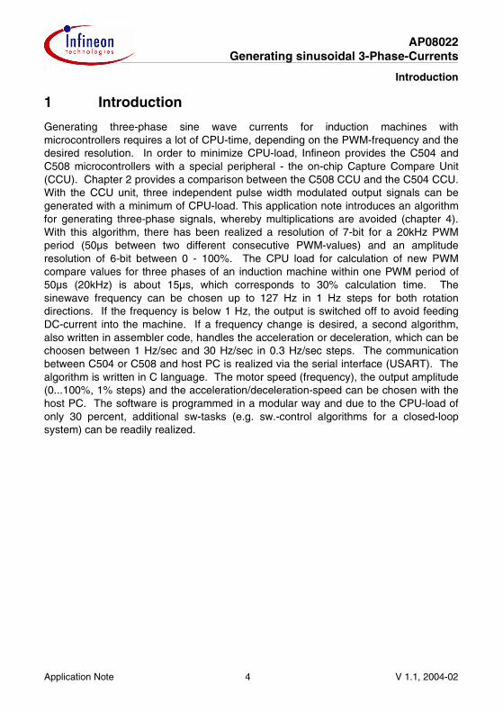
1 Introduction
Generating three-phase sine wave currents for induction machines with microcontrollers requires a lot of CPU-time, depending on the PWM-frequency and the desired resolution. In order to minimize CPU-load, Infineon provides the C504 and C508 microcontrollers with a special peripheral - the on-chip Capture Compare Unit (CCU). Chapter 2 provides a comparison between the C508 CCU and the C504 CCU. With the CCU unit, three independent pulse width modulated output signals can be generated with a minimum of CPU-load. This application note introduces an algorithm for generating three-phase signals, whereby multiplications are avoided (chapter 4). With this algorithm, there has been realized a resolution of 7-bit for a 20kHz PWM period (50µs between two different consecutive PWM-values) and an amplitude resolution of 6-bit between 0 - 100%. The CPU load for calculation of new PWM compare values for three phases of an induction machine within one PWM period of 50µs (20kHz) is about 15µs, which corresponds to 30% calculation time. The sinewave frequency can be chosen up to 127 Hz in 1 Hz steps for both rotation directions. If the frequency is below 1 Hz, the output is switched off to avoid feeding DC-current into the machine. If a frequency change is desired, a second algorithm, also written in assembler code, handles the acceleration or deceleration, which can be choosen between 1 Hz/sec and 30 Hz/sec in 0.3 Hz/sec steps. The communication between C504 or C508 and host PC is realized via the serial interface (USART). The algorithm is written in C language. The motor speed (frequency), the output amplitude (0...100%, 1% steps) and the acceleration/deceleration-speed can be chosen with the host PC. The software is programmed in a modular way and due to the CPU-load of only 30 percent, additional sw-tasks (e.g. sw.-control algorithms for a closed-loop system) can be readily realized.
AP08022 Generating sinusoidal 3-Phase-Currents
Comparison of the CCU of the C508 with the C504
Application Note 5 V 1.1, 2004-02
2 Comparison of the CCU of the C508 with the C504
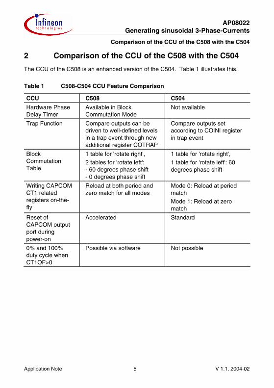
The CCU of the C508 is an enhanced version of the C504. Table 1 illustrates this.
Table 1 C508-C504 CCU Feature Comparison
CCU C508 C504
Hardware Phase Delay Timer
Available in Block Commutation Mode
Not available
Trap Function Compare outputs can be driven to well-defined levels in a trap event through new additional register COTRAP
Compare outputs set according to COINI register in trap event
Block Commutation Table
1 table for 'rotate right', 2 tables for 'rotate left': - 60 degrees phase shift - 0 degrees phase shift
1 table for 'rotate right', 1 table for 'rotate left': 60 degrees phase shift
Writing CAPCOM CT1 related registers on-the-fly
Reload at both period and zero match for all modes
Mode 0: Reload at period match Mode 1: Reload at zero match
Reset of CAPCOM output port during power-on
Accelerated Standard
0% and 100% duty cycle when CT1OF>0
Possible via software Not possible

AP08022 Generating sinusoidal 3-Phase-Currents
Fundamentals of Operation
Application Note 6 V 1.1, 2004-02
3 Fundamentals of Operation
3.1 Controlling Three-Phase Induction Motors
Usually, induction machines are supplied directly from the 50/60Hz three-phase AC voltage line, where amplitude and frequency are constant.
Figure 1 Three-Phase Sine Wave Currents for Induction Motors
Amplitude
t
Period Time (1/f)
1/3 T (120°)
Phase U Phase V Phase W
0
/t Diagram
AP08022 Generating sinusoidal 3-Phase-Currents
Fundamentals of Operation
Application Note 7 V 1.1, 2004-02
Using supply from the line, the drive cannot be regulated in a simple way. The delivered torque and speed of an induction machine are determined by the amplitude and frequency of the driving AC voltage.
Rotation speed of the shaft strongly depends on the AC frequency, and torque strongly depends on the AC current amplitude. Knowing this, a proper working open loop control can be realized by applying three sine waves with constant electrical phase shift of 120° to each other - but with variable amplitude and frequency.
As rotor slip (difference between rotor frequency and stator frequency) can vary as a function of these parameters, it is difficult to regulate exactly the rotation speed.
In many applications, where a rotor frequency deviation of a few per cents does not matter (e.g. fan, driven by three-phase induction machine), the proposed open loop control is a low cost and very powerful solution.
3.2 Generating Variable Motor Currents by Using Pulse Width Modulation (PWM)
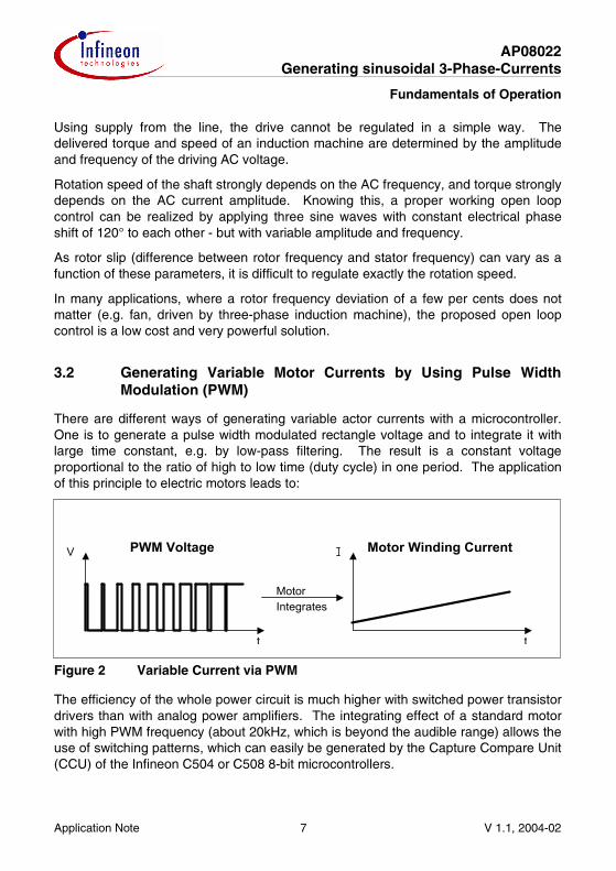
There are different ways of generating variable actor currents with a microcontroller. One is to generate a pulse width modulated rectangle voltage and to integrate it with large time constant, e.g. by low-pass filtering. The result is a constant voltage proportional to the ratio of high to low time (duty cycle) in one period. The application of this principle to electric motors leads to:
Figure 2 Variable Current via PWM
The efficiency of the whole power circuit is much higher with switched power transistor drivers than with analog power amplifiers. The integrating effect of a standard motor with high PWM frequency (about 20kHz, which is beyond the audible range) allows the use of switching patterns, which can easily be generated by the Capture Compare Unit (CCU) of the Infineon C504 or C508 8-bit microcontrollers.
t
V PWM Voltage Motor Winding Current
t
MotorIntegrates
AP08022 Generating sinusoidal 3-Phase-Currents
Fundamentals of Operation
Application Note 8 V 1.1, 2004-02
3.3 Power Amplification of Controller Output Signals by Semiconductor Bridges
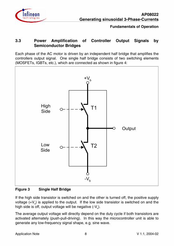
Each phase of the AC motor is driven by an independent half bridge that amplifies the controllers output signal. One single half bridge consists of two switching elements (MOSFETs, IGBTs, etc.), which are connected as shown in figure 4:
Figure 3 Single Half Bridge
If the high side transistor is switched on and the other is turned off, the positive supply voltage (+Vb) is applied to the output. If the low side transistor is switched on and the high side is off, output voltage will be negative (-Vb).
The average output voltage will directly depend on the duty cycle if both transistors are activated alternately (push-pull-driving). In this way the microcontroller unit is able to generate any low-frequency signal shape, e.g. sine wave.
T1
T2
Output
HighSide
LowSide
+Vb
-Vb
AP08022 Generating sinusoidal 3-Phase-Currents
Fundamentals of Operation
Application Note 9 V 1.1, 2004-02
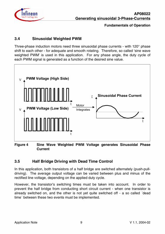
3.4 Sinusoidal Weighted PWM
Three-phase induction motors need three sinusoidal phase currents - with 120° phase shift to each other - for adequate and smooth rotating. Therefore, so called ‘sine wave weighted PWM’ is used in this application. For any phase angle, the duty cycle of each PWM signal is generated as a function of the desired sine value.
Figure 4 Sine Wave Weighted PWM Voltage generates Sinusoidal Phase Current
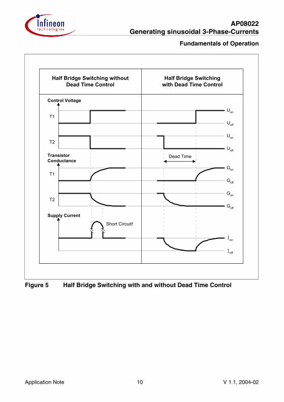
3.5 Half Bridge Driving with Dead Time Control
In this application, both transistors of a half bridge are switched alternately (push-pull-driving). The average output voltage can be varied between plus and minus of the rectified line voltage, depending on the applied duty cycle.
However, the transistor’s switching times must be taken into account. In order to prevent the half bridge from conducting short circuit current - when one transistor is already switched on, and the other is not yet quite switched off - a so called ´dead time´ between these two events must be implemented.
MotorIntegrates
V PWM Voltage (High Side)
t
t
V PWM Voltage (Low Side)
t
Sinusoidal Phase Current
AP08022 Generating sinusoidal 3-Phase-Currents
Fundamentals of Operation
Application Note 10 V 1.1, 2004-02
Figure 5 Half Bridge Switching with and without Dead Time Control
Control Voltage
TransistorConductance
Supply Current
Short Circuit!
Half Bridge Switching withoutDead Time Control
Half Bridge Switchingwith Dead Time Control
Dead Time
T1
T2
T1
T2
Uon
Uon
Gon
Gon
on
off
Goff
Goff
Uoff
Uoff

AP08022 Generating sinusoidal 3-Phase-Currents
Fundamentals of Operation
Application Note 11 V 1.1, 2004-02
3.6 Principle of Generating Sinusoidal Weighted PWM Signals with the C504 and C508
The microcontroller can be easily programmed to provide up to three independent sine waves by using the PWM capability of its on-chip Capture Compare Unit (CCU). The center aligned (symmetrical) up to three PWM channels with dead time are generated by the 16-bit wide compare timer 1 as follows:
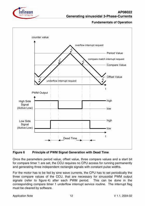
An up/down counter counts from 0 up to a programmable 16-bit period value stored in the special function register (SFR) CCPx. When reaching the period value, the count direction is changed from up-counting to down-counting. When the count value becomes 0, the count direction will be switched to upwards again. This is similar to the function of a triangle generator. Additionally, compare timer 1 over/underflow interrupt requests are activated.
The PWM output signals for the three phases of an induction machine are specified by the three compare values stored in three independent 16-bit compare registers CCHx and CCLx where x=0-2. When compare timer 1 oversteps the 16-bit compare values for the three PWM output signals, the corresponding outputs toggle and the compare match interrupts requests for the three PWM signals are activated. As a result, up to three digital rectangle signals are generated (the duty cycle of one PWM channel corresponds to the position of the compare value between offset and period value). The switching frequency is identical to the counter underflow frequency (e.g. 20kHz). These signals control the high side transistors of the single half bridges.
Furthermore, output signals are generated at the COUTx pins, which control the low side switches. The passive levels of the CCx and COUTx pins are default based on the values written to SFR COINI and therefore, each COUTx can be the complement of its CCx. A global programmable dead time for each PWM channel, in which both switches are turned off can be programmed by an additional 16-bit offset value stored in SFRs CT1OFH and CT10FL.
The principle for one PWM channel is shown in figure 6.
AP08022 Generating sinusoidal 3-Phase-Currents
Fundamentals of Operation
Application Note 12 V 1.1, 2004-02
Figure 6 Principle of PWM Signal Generation with Dead Time
Once the parameters period value, offset value, three compare values and a start bit for compare timer 1 are set, the CCU requires no CPU access for running permanently and generating three independent rectangle signals with constant pulse widths.
For the motor has to be fed by sine wave currents, the CPU has to set periodically the three compare values of the CCU, that are necessary for sinusoidal PWM output signals (refer to figure 4) after each PWM period. This can be done in the corresponding compare timer 1 underflow interrupt service routine. The interrupt flag must be cleared by software.
t
counter value
Period Value
Compare Value
Offset Value
PWM Output
t
low
high
high
low
Dead Time
High SideSignal
(Active Low)
Low SideSignal
(Active Low)
overflow interrupt request
underflow interrupt request
compare match interrupt request
AP08022 Generating sinusoidal 3-Phase-Currents
Hardware Description
Application Note 13 V 1.1, 2004-02
4 Hardware Description
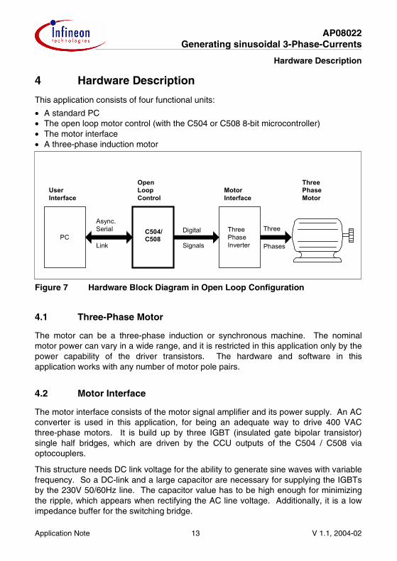
This application consists of four functional units:
• A standard PC • The open loop motor control (with the C504 or C508 8-bit microcontroller) • The motor interface • A three-phase induction motor
Figure 7 Hardware Block Diagram in Open Loop Configuration
4.1 Three-Phase Motor
The motor can be a three-phase induction or synchronous machine. The nominal motor power can vary in a wide range, and it is restricted in this application only by the power capability of the driver transistors. The hardware and software in this application works with any number of motor pole pairs.
4.2 Motor Interface
The motor interface consists of the motor signal amplifier and its power supply. An AC converter is used in this application, for being an adequate way to drive 400 VAC three-phase motors. It is build up by three IGBT (insulated gate bipolar transistor) single half bridges, which are driven by the CCU outputs of the C504 / C508 via optocouplers.
This structure needs DC link voltage for the ability to generate sine waves with variable frequency. So a DC-link and a large capacitor are necessary for supplying the IGBTs by the 230V 50/60Hz line. The capacitor value has to be high enough for minimizing the ripple, which appears when rectifying the AC line voltage. Additionally, it is a low impedance buffer for the switching bridge.
User Interface
PC
Motor Interface
Open Loop Control
Three Phase Motor
Async. Serial
Link
C504/C508
Three Phase Inverter
Digital
Signals
Three
Phases

AP08022 Generating sinusoidal 3-Phase-Currents
Hardware Description
Application Note 14 V 1.1, 2004-02
Figure 8 Simplified AC Converter Schematic Diagram
T1
T2
T3
T4
T5
T6
L
N
230VAC
U
V
W
Udrive
DigitalCCUControlSignals
fromC504 / C508
(PWM) O1...O6
DC-Link Three Phase Bridge (IGBT's)
to Motorto Line
Opto Couplers
D1
D2
D3
D4
325
VDC
C
Capacitor

AP08022 Generating sinusoidal 3-Phase-Currents
Hardware Description
Application Note 15 V 1.1, 2004-02
4.3 Open Loop Motor Control
The following block diagram shows the digital control unit C504 / C508 for three-phase motor control. For this application the following internal peripheral resources are used:
• USART for RS232 host computer communication • timer 2 (C504) / dedicated baud rate generator (C508) as baud rate generator • CCU (Capture Compare Unit) for PWM output and timer interrupt generation
Open Loop Motor Control with the C504 / C508, using its CCU
Timer 2/USART
CCU
CPU
Settings
Interrupts
Data
RAM
CC0
COUT0
CC1
COUT1
CC2
COUT2
U HighU LowV HighV LowW HighW Low
TxD
RxD
to Bridge:
C504 / C508 Microcontroller
To Hostvia RS232
P1.2
P1.3
P1.4
P1.5
P1.6
P1.7
P3.0
P3.1
AP08022 Generating sinusoidal 3-Phase-Currents
C504 Software Description
Application Note 16 V 1.1, 2004-02
5 C504 Software Description
The software description in this chapter is made with reference to the C504 code. Since the C508 code is generated based on the C504 code with some modifications, the C504 software description is generally applicable to the C508 software.
5.1 Fundamental Considerations
The most important task of the microcontroller is to generate three sine waves with variable frequency and amplitude in very short time frames. This chapter describes how the microcontroller software basically meets this requirement.
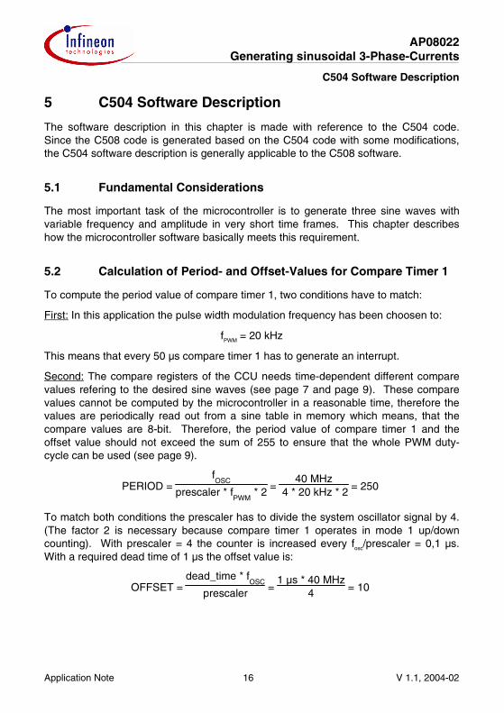
5.2 Calculation of Period- and Offset-Values for Compare Timer 1
To compute the period value of compare timer 1, two conditions have to match:
First: In this application the pulse width modulation frequency has been choosen to:
fPWM = 20 kHz
This means that every 50 µs compare timer 1 has to generate an interrupt.
Second: The compare registers of the CCU needs time-dependent different compare values refering to the desired sine waves (see page 7 and page 9). These compare values cannot be computed by the microcontroller in a reasonable time, therefore the values are periodically read out from a sine table in memory which means, that the compare values are 8-bit. Therefore, the period value of compare timer 1 and the offset value should not exceed the sum of 255 to ensure that the whole PWM duty-cycle can be used (see page 9).
PERIOD = fOSC
prescaler * fPWM
* 2 = 40 MHz
4 * 20 kHz * 2 = 250
To match both conditions the prescaler has to divide the system oscillator signal by 4. (The factor 2 is necessary because compare timer 1 operates in mode 1 up/down counting). With prescaler = 4 the counter is increased every fosc/prescaler = 0,1 µs. With a required dead time of 1 µs the offset value is:
OFFSET = dead_time * f
OSC
prescaler = 1 µs * 40 MHz
4 = 10
AP08022 Generating sinusoidal 3-Phase-Currents
C504 Software Description
Application Note 17 V 1.1, 2004-02
5.3 Considerations concerning the Resolution for the Sine Table Pointers
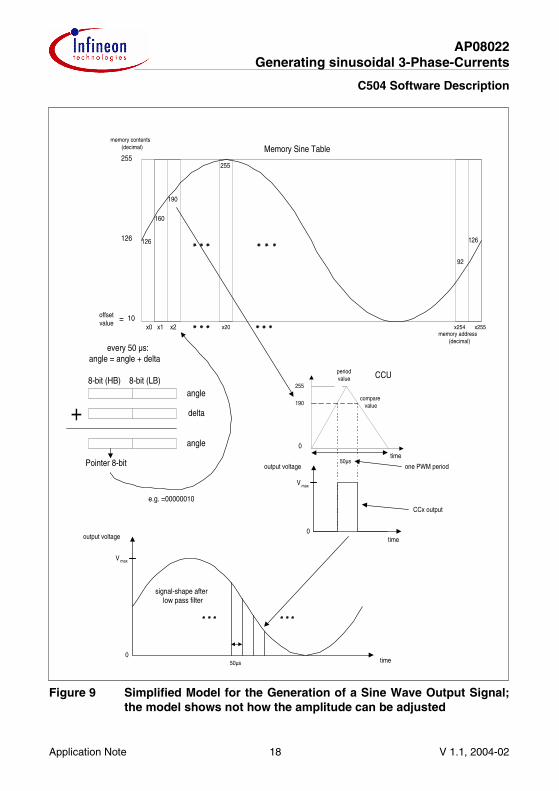
For accessing the look-up table values in short time, the sine table should be not longer than 256 bytes for one period because the pointer (named angle variable) can be an 8-bit value and easily handled by the 8-bit microcontroller. To generate the sine waves, the angle variable is increased every interrupt and points to a value in the sine table which is read out and moved to the compare value register. The lowest frequency to be generated is 1 Hz. Due to the angle variable being increased every 50 µs and pointing to another compare value in the sine table, the frequency of the output signal will be:
frequency = 1
256 * 50 µs = 78.125 kHz
That means for lower frequencies pointing on the same sine table value more than one time e.g. for 1 Hz about 78 times. The best solution for this problem is to take a 16-bit pointer angle variable with only the high byte being the pointer to the sine table. Supposing the 16-bit angle variable will be increased by one every 50 µs it takes
65536 * 50 µs = 3.27 s
to access every value in the table once, that means the lowest frequency then results to 0.305Hz (which corresponds to the minimum value of the 16-bit resolution for the electrical rotating field of the induction machine). To generate any other frequency every 50µs a certain delta value has to be added to the angle variable computed as follows:
delta = frequency0.305 Hz = frequency * 65536 * 50 µs =
frequency * 6553620 kHz
angle = angle + delta
In figure 10, a simplified model for the generation of a sine wave output signal by using the above described mechanism is shown.
AP08022 Generating sinusoidal 3-Phase-Currents
C504 Software Description
Application Note 18 V 1.1, 2004-02
Figure 9 Simplified Model for the Generation of a Sine Wave Output Signal; the model shows not how the amplitude can be adjusted
every 50 µs:angle = angle + delta
8-bit (HB) 8-bit (LB)
+angle
delta
angle
Pointer 8-bit
time
e.g. =00000010
50µs0
V max
memory address(decimal)
x0
126
10
126
255
memory contents(decimal)
126
190
160
255
x1 x255x254x2
Memory Sine Table
x20
92
offsetvalue
signal-shape afterlow pass filter
=
output voltage
output voltage one PWM period
255
periodvalue
0time
190
time
comparevalue
50µs
0
V max
CCU
CCx output
AP08022 Generating sinusoidal 3-Phase-Currents
C504 Software Description
Application Note 19 V 1.1, 2004-02
5.4 Changing the Amplitude without using any Multiplication-Instruction
With the 8-bit CPU of the microcontroller, one signed 8-bit x 8-bit multiplication takes a lot of cycles. This leads to a relatively long execution time, which cannot be tolerated in all cases. Furthermore, if a higher resolution shall be used, even more computing power is needed. The proposed algorithm is based on an addition theorem for sine waves. It can be used to reduce computing time for signed multiplication.
The following equation describes one of the desired three-phase sine waves at the induction machine:
U = A * sin B
B corresponds to the angle variable high byte, sin B corresponds to the value in the sine table to be multiplied with the amplitude A, U corresponds to the value moved to the compare register. To avoid the multiplication, following equation shows a solution:
U = A * sin B = cos(arccos A) * sin B = cos A' * sin B = 12 * [sin(B - A) + sin(B + A')]
with:
A' = arccos A
cos a * sin b = 12 * [sin(b - a) * sin(b + a)] (addition theorem)
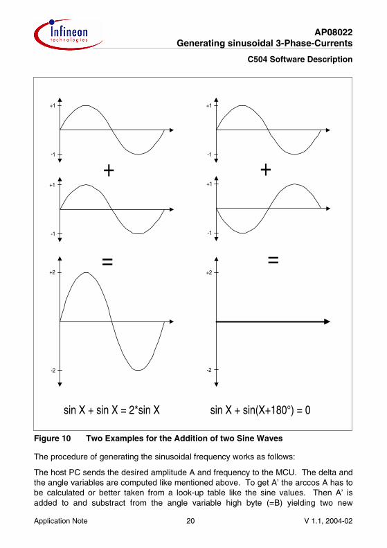
The multiplication of A and sinB is now transfered with an addition theorem into the operations B-A’ and B+A’ and two sine table accesses. Figure 11 gives a impression why the equation can be used. Two examples of an addition of two sine waves are shown. In the first case the sine wave have no phase shift. In the second case the sine waves are 180° phase shifted. Due to this addition, the desired amplitude between 0 and 2 can be obtained by adapting the phase shift between the two sine waves. The factor ½ is necessary to transfer the range to 0....1.
AP08022 Generating sinusoidal 3-Phase-Currents
C504 Software Description
Application Note 20 V 1.1, 2004-02
Figure 10 Two Examples for the Addition of two Sine Waves
The procedure of generating the sinusoidal frequency works as follows:
The host PC sends the desired amplitude A and frequency to the MCU. The delta and the angle variables are computed like mentioned above. To get A’ the arccos A has to be calculated or better taken from a look-up table like the sine values. Then A’ is added to and substract from the angle variable high byte (=B) yielding two new
+1
-1
+1
-1
+2
-2
=
+
+1
-1
+
=
+1
-1
+2
-2
sin X + sin X = 2*sin X sin X + sin(X+180°) = 0
AP08022 Generating sinusoidal 3-Phase-Currents
C504 Software Description
Application Note 21 V 1.1, 2004-02
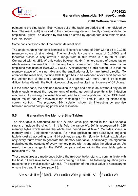
pointers to the sine table. Both values out of the table are added and then divided by two. The result (=U) is moved to the compare register and directly corresponds to the amplitude. (Hint: The division by two can be saved by appropriate sine table values, see next page).
Some considerations about the amplitude resolution:
The angle variable high byte identical to B covers a range of 360° with 8-bit = 0...255 (memory space of sine table). The amplitude A covers a range of 0...100% and therefore arccos A only covers a range from 0...90° which is a fourth of 360°. Compared with 0...255, A’ only varies between 0...64 (memory space of arccos table) which means the resolution of the amplitude is maximum 6-bit. The result is an amplitude resolution of 100%/64 = 1,56%. A disadvantage of this procedure is that the memory space of the sine table and the amplitude-resolution are linked directly. To enhance the resolution, the sine table length has to be extended above 8-bit and either the pointer part of the angle variable. But a pointer with more than 8 bit is more difficult to handle with the 8-bit microcontroller, and results in an increase of CPU-time.
On the other hand, the obtained resolution in angle and amplitude is without any doubt high enough to meet the requirements of midrange control algorithms for induction machines. Increasing the resolution will lead to an unproportional higher CPU load. Better results can be achieved if the remaining CPU time is used for closed-loop current control. The proposed 8-bit solution shows an interesting compromise between required computing power and resolution.
5.5 Generating the Memory Sine Tables
The sine table is computed out of a ¼ sine wave part stored in the field variable sine_src (include file sine.h). In this field the range 0°...90° is represented in 255 memory bytes which means the whole sine period would take 1024 bytes space in memory and a 10-bit pointer variable. As in this application, only a 256 byte long sine table is desired according to an 8 bit pointer, an algorithm (function init_sine_tbl) takes only every fourth value to generate the memory sine table. Additionally, the algorithm multiplicates the contents of every memory place with ½ and adds the offset value. As result, the data range for the PWM compare values within the sine table gets a resolution of 7-bit.
These measures are made once before the microcontroller starts to communicate with the host PC and save some instructions during run time. The following equation gives reasons for the multiplication with 0.5. The addition of the offset value is neccesary to ensure the dead time (see page 9 ).
U = A * sin B = 12 * [sin(B - A') + sin(B + A')] =
12 * sin(B - A') +
12 * sin(B + A')
AP08022 Generating sinusoidal 3-Phase-Currents
C504 Software Description
Application Note 22 V 1.1, 2004-02
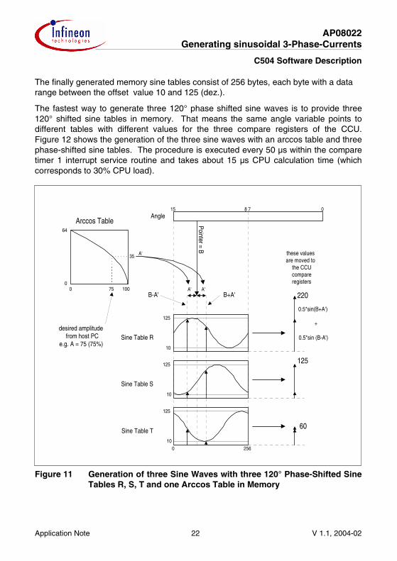
The finally generated memory sine tables consist of 256 bytes, each byte with a data range between the offset value 10 and 125 (dez.).
The fastest way to generate three 120° phase shifted sine waves is to provide three 120° shifted sine tables in memory. That means the same angle variable points to different tables with different values for the three compare registers of the CCU. Figure 12 shows the generation of the three sine waves with an arccos table and three phase-shifted sine tables. The procedure is executed every 50 µs within the compare timer 1 interrupt service routine and takes about 15 µs CPU calculation time (which corresponds to 30% CPU load).
Figure 11 Generation of three Sine Waves with three 120° Phase-Shifted Sine Tables R, S, T and one Arccos Table in Memory
Pointer = B
A'
00
64
100
Angle08 715
10
125
10
125
10
125
A' A'
these valuesare moved to
the CCUcompareregisters
Sine Table R
Sine Table S
Sine Table T
0 256
Arccos Table
desired amplitudefrom host PC
e.g. A = 75 (75%)
75
35
220
60
125
B-A' B+A'
0.5*sin(B+A')
+
0.5*sin (B-A')
AP08022 Generating sinusoidal 3-Phase-Currents
C504 Software Description
Application Note 23 V 1.1, 2004-02
5.6 Compare Timer 1 Interrupt Service Routine Tasks
The CCU compare register values are updated periodically every 50µs in the compare timer 1 underflow interrupt service routine. This task takes about 15µs, which corresponds to 30% of CPU-load. If a frequency change is required, a second task has to be started. To accelerate or decelerate the induction machine, the electrical rotating field for the induction machine has to be increased or decreased with a certain adjustable rate. To handle this task, every x ms for one PWM period (depending on the desired acceleration or deceleration speed), the delta value is increased or decreased until the new frequency of the rotating field is reached. With regard to a rotation direction change, the frequency can be decreased down to zero. To avoid feeding DC current to the machine, the delta variable is observed and the CCU output is switched off if delta is below 1Hz. During the acceleration/deceleration task, the CPU-load is temporally extended every x ms up to 60% (30µs calculation time) for one PWM period.
5.7 Main Program Task
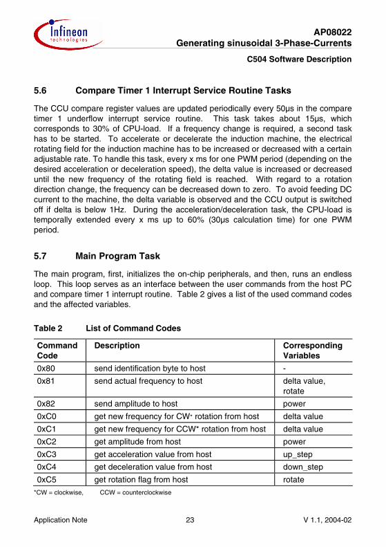
The main program, first, initializes the on-chip peripherals, and then, runs an endless loop. This loop serves as an interface between the user commands from the host PC and compare timer 1 interrupt routine. Table 2 gives a list of the used command codes and the affected variables.
Table 2 List of Command Codes
Command Code
Description Corresponding Variables
0x80 send identification byte to host -
0x81 send actual frequency to host delta value, rotate
0x82 send amplitude to host power
0xC0 get new frequency for CW* rotation from host delta value
0xC1 get new frequency for CCW* rotation from host delta value
0xC2 get amplitude from host power
0xC3 get acceleration value from host up_step
0xC4 get deceleration value from host down_step
0xC5 get rotation flag from host rotate
*CW = clockwise, CCW = counterclockwise
AP08022 Generating sinusoidal 3-Phase-Currents
C504 Software Description
Application Note 24 V 1.1, 2004-02
5.8 Differences between the C504 code and the C508 code
The modifications made on the C504 code to generate the C508 code includes
1. SFR change to C508, 2. SFR definition changes, 3. Serial communication via USART using dedicated baud rate generator for baud rate
generation, 4. Change in operating (CPU) frequency (to 20MHz) due to microcontroller feature,
and 5. External trap, /CTRAP, enabled.
Baud rate generation using the dedicated baud rate generator of C508 microcontroller leaves timer 2 free for other functions.
The maximum CPU frequency for the C508 microcontroller is 20MHz while that for the C504 microcontroller is 40MHz. Each code is written for each microcontroller to run at their respective maximum CPU frequency. At these frequencies, both microcontrollers will run with the same instruction cycle time of 300ns. Therefore, at a desired n = revolution per min, the frequency of the sinusoidal waves generated at the CCx and COUTx outputs is the same for both the C508 and C504.
Besides the emergency stop that the user can activate via the pc host software anytime, there is an additional interrupt that is activated by incoming signal at pin /CTRAP of the microcontroller which puts the levels of the CCx and COUTx outputs immediately to that defined in SFR COTRAP. The Trap State is enabled for the outputs by setting corresponding bits in SFR TRCON. The code is written with the assumption that the three phase bridge is made up of the same transistor type in both high and low side, so when trap occurs, the CCU outputs are initialised to remain at the same passive level. It has been programmed such that after release of pin /CTRAP, the CCU will only resume operation by a reset on the microcontroller.
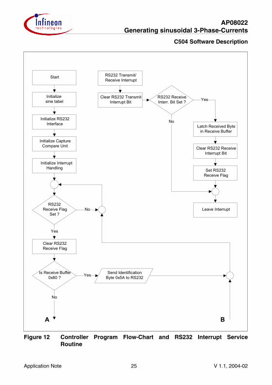
5.9 Flow-Charts
The flow-charts in the following figures are applicable to both the C504 and C508 software for controlling a three-phase induction machine.
Figure 13 shows the RS232 interrupt service routine, which is necessary for receiving bytes via serial link from the host PC (sending bytes via serial link is performed directly in the main program) and the first part of the main program flow-chart.
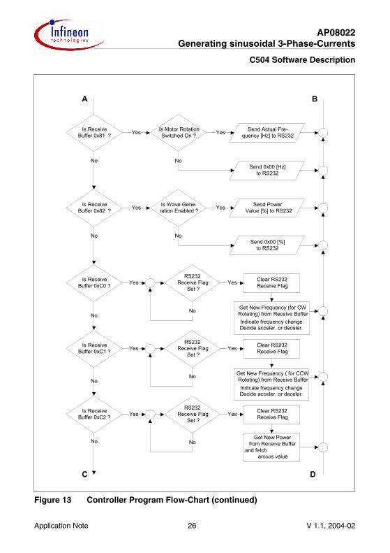
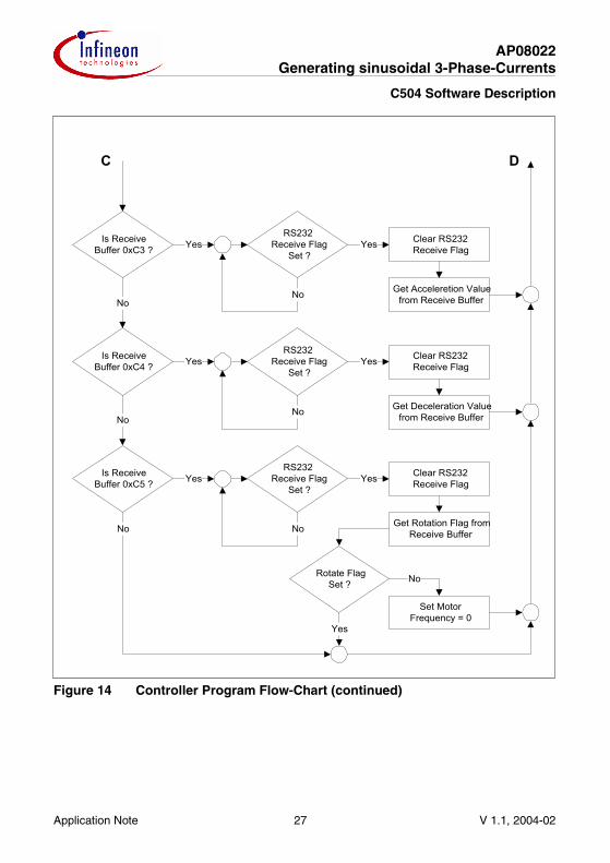
Figure 14 and 15 contains the remaining main program flow-charts.
In Figure 16, the timer interrupt flow-chart can be found.
AP08022 Generating sinusoidal 3-Phase-Currents
C504 Software Description
Application Note 25 V 1.1, 2004-02
Figure 12 Controller Program Flow-Chart and RS232 Interrupt Service Routine
Initialize InterruptHandling
RS232Receive Flag
Set ?
Yes
Is Receive Buffer0x80 ? Yes
No
A B
Send IdentificationByte 0x5A to RS232
Clear RS232Receive Flag
Yes
Initialize CaptureCompare Unit
Initialize RS232Interface
RS232 Transmit/Receive Interrupt
Clear RS232 TransmitInterrupt Bit
RS232 ReceiveInterr. Bit Set ?
NoLatch Received Byte
in Receive Buffer
Clear RS232 ReceiveInterrupt Bit
Set RS232Receive Flag
No Leave Interrupt
Start
Initializesine tabel
AP08022 Generating sinusoidal 3-Phase-Currents
C504 Software Description
Application Note 26 V 1.1, 2004-02
Figure 13 Controller Program Flow-Chart (continued)
A B
RS232Receive Flag
Set ?Yes Clear RS232
Receive FlagIs Receive
Buffer 0xC0 ? Yes
Get New Frequency (for CWRotating) from Receive BufferNo
RS232Receive Flag
Set ?Yes Clear RS232
Receive FlagIs Receive
Buffer 0xC1 ? Yes
Get New Frequency ( for CCWRotating) from Receive BufferNo
RS232Receive Flag
Set ?Yes Clear RS232
Receive FlagIs Receive
Buffer 0xC2 ? Yes
Get New Powerfrom Receive Buffer
and fetcharccos value
No
No
No
No
Is ReceiveBuffer 0x81 ?
Is ReceiveBuffer 0x82 ?
Yes Send Actual Fre-quency [Hz] to RS232
Send 0x00 [Hz]to RS232
Yes Send Power Value [%] to RS232
Is Wave Gene-ration Enabled ? Yes
Send 0x00 [%]to RS232
NoNo
No
Is Motor RotationSwitched On ? Yes
No
C D
Indicate frequency changeDecide acceler. or deceler.
Indicate frequency changeDecide acceler. or deceler.
AP08022 Generating sinusoidal 3-Phase-Currents
C504 Software Description
Application Note 27 V 1.1, 2004-02
Figure 14 Controller Program Flow-Chart (continued)
C D
RS232Receive Flag
Set ?Yes Clear RS232
Receive FlagIs Receive
Buffer 0xC3 ? Yes
Get Acceleretion Valuefrom Receive BufferNo
RS232Receive Flag
Set ?Yes Clear RS232
Receive FlagIs Receive
Buffer 0xC4 ? Yes
Get Deceleration Valuefrom Receive BufferNo
RS232Receive Flag
Set ?Yes Clear RS232
Receive FlagIs Receive
Buffer 0xC5 ? Yes
Get Rotation Flag fromReceive Buffer
Rotate FlagSet ?
Set MotorFrequency = 0
Yes
No
No
No
No
No

AP08022 Generating sinusoidal 3-Phase-Currents
C504 Software Description
Application Note 28 V 1.1, 2004-02
Figure 15 Controller Program Flow-Chart - Compare Timer 1 Interrupt Service Routine
Compare Timer 1Interrupt
anlge = angle +delta
calculateangle +
arccos(power)
calculateangle - arccos(power)
load CCU with newsine wave values
frequencychange ?
decrement interruptcounter
interrupt counter =0 ?
decreasefrequency ?
delta = delta +up_step
frequency changefinished
ABS (frequency) <1Hz ?
leave interrupt
Decrea. frequencydelta > delta_new?
increase frequencydelta < delta_new
delta = delta -down_step
frequency changefinished
enable poweroutput
dissable poweroutput
No
Yes
YesYes
Yes
Yes
NoNo
No
No
Yes
No
15µs
16...17µs
30µs
AP08022 Generating sinusoidal 3-Phase-Currents
Conclusion
Application Note 29 V 1.1, 2004-02
6 Conclusion
The versatile structure of the on-chip Capture Compare Unit of the Infineon microcontrollers C504 and C508 allows an easy generation of three sine wave currents, dedicated to the control of inductance drives. Thanks to a time-optimized algorithm, all control tasks can be handled in a very efficient way, requiring only few CPU-computing time.
The proposed communication protocol (via serial channel) with a host PC shows the flexibility of the combination of the well known C500 family with a new powerful Capture Compare Unit.
This application note proposes a HW- and SW- structure dedicated for AC drive control. Due to the integrated peripherals in the C504 and C508, very few external components are necessary, so the total system costs are reduced.
The implementation of this open-loop induction drive control algorithms with low CPU load shows the first step towards closed-loop control solutions for mid-range applications. The adapted structure of the C504 and C508 leads to a very interesting compromise between system costs and its performance.

h t t p : / / w w w . i n f i n e o n . c o m
Published by Infineon Technologies AG