software for the robot-operated inspection …
TRANSCRIPT
A. Burghardt i dr. Softver za robotom upravljanu kontrolnu stanicu za statorske lopatice motora s obzirom na geometrijsku promjenljivost dijelova
Tehnički vjesnik 24, Suppl. 2(2017), 349-353 349
ISSN 1330-3651 (Print), ISSN 1848-6339 (Online) https://doi.org/10.17559/TV-20160820142224
SOFTWARE FOR THE ROBOT-OPERATED INSPECTION STATION FOR ENGINE GUIDE VANES TAKING INTO CONSIDERATION THE GEOMETRIC VARIABILITY OF PARTS Andrzej Burghardt, Krzysztof Kurc, Dariusz Szybicki, Magdalena Muszyńska, Jacek Nawrocki
Original scientific paper The paper presents a process of designing and building software for a robotic test stand used for inspection of stators. The software was developed for a test stand comprising the ABB IRB 140 robotic manipulator, and a PC workstation that handles two ultrasound sensors and runs the LabVIEW software suite. The control algorithms of the robot include the potential differences in the geometric features of the items inspected on the test stand and the resulting differences in the manipulator tool motion paths. The software was designed for and delivered to Pratt & Whitney Rzeszów Sp. z o.o. Keywords: industrial robots; non-destructive testing; robotic cells; robot software; robotic measurement Softver za robotom upravljanu kontrolnu stanicu za statorske lopatice motora s obzirom na geometrijsku promjenljivost dijelova
Izvorni znanstveni članak U radu je prikazan proces projektiranja i izgradnje softvera za robotsku ispitnu stanicu koja se koristi za provjeru statora. Softver je razvijen za stanicu sa ABB IRB 140 robotskim manipulatorom i PC radnom stanicom koja upravlja s dva ultrazvučna senzora i pokreće LabVIEW softverski paket. Kontrolni algoritmi robota uključuju potencijalne razlike u geometrijskim značajkama pregledanih elemenata na ispitnoj stanici i nastalim razlikama u stazama kretanja manipulatora alata. Softver je dizajniran i isporučen Pratt & Whitney Rzeszów Sp. z o.o. Ključne riječi: industrijski roboti; mjerenja robotom; nerazorna ispitivanja; robotske ćelije; robotski softver 1 Introduction
The robot of the designed test stand is responsible for collecting a fixture cassette with a stator installed and for measuring the vane wall thickness. The stators with the vanes are intended for the Airbus A380 aircraft jet engine. The measurement is based on the UTT method. Aside from CT (computer tomography) [3] and eddy current defectoscopy [5], the applied UTT measurement [4] method is one of the most popular NDT methods in quality inspection of castings. The designed robotic test station and its software are intended to replace the manual measurement method that employs a measurement template and a handheld flaw detector. The manual measurement method takes ca. 6 h and carries an inherent risk of human error.
The measured nickel superalloy stators are manufactured by investment cored casting [7]. Despite the advancement of this casting method, the produced details may vary by several percent in form geometry, which is due to casting solidification and several other effects during cooling of the casting. The potential geometrical deviations from the CAD model of the casting and between the individual castings require that the design of the robotic test station and its software considers the dimensional differences and their chance variation. 2 Test stand CAD model
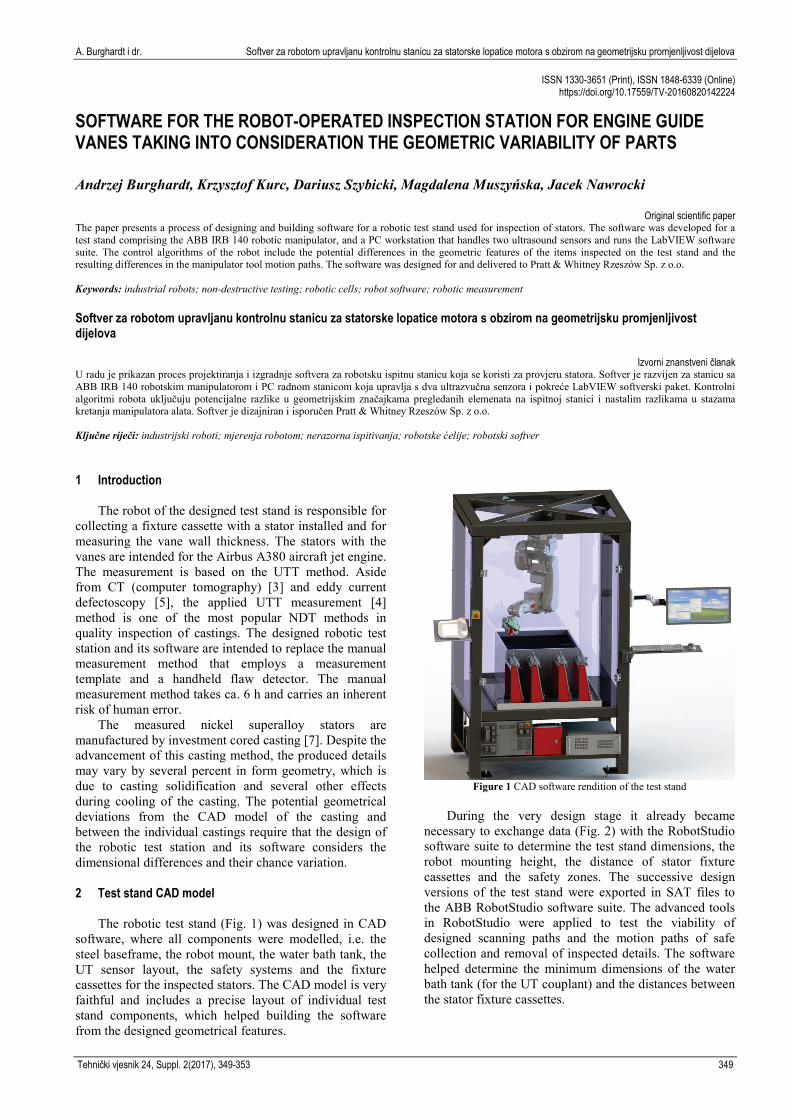
The robotic test stand (Fig. 1) was designed in CAD software, where all components were modelled, i.e. the steel baseframe, the robot mount, the water bath tank, the UT sensor layout, the safety systems and the fixture cassettes for the inspected stators. The CAD model is very faithful and includes a precise layout of individual test stand components, which helped building the software from the designed geometrical features.
Figure 1 CAD software rendition of the test stand
During the very design stage it already became
necessary to exchange data (Fig. 2) with the RobotStudio software suite to determine the test stand dimensions, the robot mounting height, the distance of stator fixture cassettes and the safety zones. The successive design versions of the test stand were exported in SAT files to the ABB RobotStudio software suite. The advanced tools in RobotStudio were applied to test the viability of designed scanning paths and the motion paths of safe collection and removal of inspected details. The software helped determine the minimum dimensions of the water bath tank (for the UT couplant) and the distances between the stator fixture cassettes.

Software for the robot-operated inspection station for engine guide vanes taking into consideration the geometric variability of parts A. Burghardt et al.
350 Technical Gazette 24, Suppl. 2(2017), 349-353
Figure 2 Cooperation CAD software and RobotStudio
The mechatronic approach to the robot test stand
design was based on the cooperation and data exchange between the CAD system and the robot programming software [6]. This helped to avoid potential design errors and to select the essential elements of design. The CAD software was used to design the alignment of the UT measurement transceiver probe and the stator at each of the 168 determined inspection measurement points (Fig. 3).
Figure 3 Location of the UT scanning head at the measurement points
across the inspected detail
The Link and other tools available in the CAD software were necessary to use due to the complex geometry of the inspected stator and the required perpendicularity of the UT scanning probe plane to the normal plane at every measurement point across the inspected vane. Due to the nature of the inspection measurement process, the vane to stator plane surface must be ca. 5 mm, whereas the perpendicularity affects the quality of the recorded UT measurement signal. The locations of the UT scanning probe were exported to RobotStudio as cylinder positions in the CAD model. RobotStudio was then used to define 168 systems of coordinates that were required to generate the robot motion trajectory waypoints. 3 Robot offline programming
The robot controller software was programmed in
RobotStudio. RobotStudio is intended for building virtual robot cells, with offline programming and simulation of robot operations on a PC workstation running on MS Windows. RobotStudio uses the VirtualRobot™ technology by which the robot simulation is controlled by the operating system deployed in actual robot controllers. This ensures full compatibility of the designed robot programs with the actual operating environment. RobotStudio features sample libraries of ABB robots and mechanisms. The software also helps working with geometrical data from most commercially available 3D CAD systems [1]. These were the mechanisms that helped to generate the locations of the coordinate system, trajectory waypoints and paths of the robot wrist, as shown in Fig. 2 and 3.
Figure 4 Layout of the coordinate systems and tools on the test stand
Work object connected to the vane, the robot holds the
work piece - moved by the mechanical unit
Tool (left), the robot does not hold the tool
Tool (right), the robot does not hold the tool
*.sat file
CAD software
Robot wrist work
envelope
ABB RobotStudio

A. Burghardt i dr. Softver za robotom upravljanu kontrolnu stanicu za statorske lopatice motora s obzirom na geometrijsku promjenljivost dijelova
Tehnički vjesnik 24, Suppl. 2(2017), 349-353 351
The robot was programmed in the RAPID language. The essential element of the RAPID language structure is a program. A program includes modules, procedures and variables for the task present in the robot system, where the task is a single program related to a robot or a process. The program is executed in a sequence that corresponds directly to the order of insertion of instructions or subprograms. The language design permits jumps to previous and next instructions and programs, and reacting with the execution of a trap procedure to an associated interrupt or an error. The programs are designed as modules which comprise data and their operating code [2].
The designed software was assumed to have the robot operate on a fixed object, i.e. the inspected stator, and the robot tools are UT scanning probes (Fig. 4). This assumption is critical to the programming of the solution and greatly facilitates the design process.
A solution by which the scanned work object and its coordinate systems are in motion, whereas both tools are fixed, helps design the motion paths faster and modify them with much ease.
Figure 5 View of work object's coordinate systems
By importing the locations (expressed as geometrical
solids - cylinders) of the UT scanning probe at 168 measurement points from the CAD software, it was possible to define the respective coordinate systems and paths (Fig. 5, Fig. 6). In each of the coordinate systems, a measurement point on the trajectory was defined and with several waypoints for the approach to the UT scanning probe. Each of the six vanes of the stator had to be measured at seven sections and 28 measurement points. This operation is performed with four robot wrist paths. The robot software was designed to tie two of the paths with the right UT scanning probe and the other two with the left UT scanning probe (Fig. 4).
Figure 6 View of paths
4 Software procedures with geometrical variations in
details Although the designed positions of the test stand
components had been defined with utmost precision, the actual (produced) test stand was subject to a verification of positions of the installed UT scanning probes and the stator fixture cassette mounts (Fig. 7).
Figure 7 Image of the actual test stand
The verification was done by pointing the
characteristic points of the test stand components with the IRB 140 robot in the global system. This helped correcting the component alignment caused by errors in production precision and assembly.
Following preliminary testing of several castings, it became necessary to design the test stand software so that the control system of the test stand would automatically modify the locations of measurement points under certain circumstances. This was necessitated by the potential differences between the individual cast pieces ranging several millimetres in various planes. These geometrical differences prevent the UT sensors from measuring the
Fixture cassette with a stator and an example of the scanning path
Example robot path
Geometrical solids -
cylinders
Fixture stator with a stator and defined coordinate systems
Example work
object

Software for the robot-operated inspection station for engine guide vanes taking into consideration the geometric variability of parts A. Burghardt et al.
352 Technical Gazette 24, Suppl. 2(2017), 349-353
wall thickness values at certain measurement points. For those points, the echo amplitude registered in LabVIEW is too small, which prevents measurement or affects the measurement accuracy (Fig. 8).
Figure 8 UT sensor measurement signal outputs
Hence, the test stand software, which includes the
robot software and the UT probe software interfaced with it by 7 digital signals, must "sweep" the problematic measurement points (Fig. 9). The software must find the correct alignment of the stator relative to the UT sensor at the preset measurement point location In this position the echo amplitudes exceed the minimum thresholds that ensure a good measurement.
The sweep procedure was designed with the RAPID language emergency situation handling functionality. When a measurement point is reached, the robot controller sends a digital confirmation to LabVIEW. The UT measurement follows, and the echo amplitudes are recorded. If the measurement position is OK and the amplitudes exceed the minimum preset thresholds, LabVIEW acknowledges the measurement to be OK in 0.1 s and the robot moves to the next measurement point. If the controller receives no measurement OK acknowledgement in 0.2 s, it switches to emergency handling and starts the sweep.
The temporary variables are written with the current coordinate system of the measurement point and the current UT sensor (probe) in use. The variables of the measurement point coordinate system orientation are written with four positions, each different from the other by one degree. The positions are written as quaternion expressions. The four positions are: turn by +1 and −1
degree from the y-axis and turn by +1 and −1 degree from the x-axis:
orientx1 := [0.999961923,0.008726535,0,0]; orientxm1 :=[0.999961923,−0.008726535,0,0]; orienty1 := [0.999961923,0,0.008726535,0]; orientym1 := [0.999961923,0,−0.008726535,0];
Figure 9 The information flow in the robot-operated inspection station
Figure 10 Reorientation of the coordinate system
y-axis turn against initial position
ABB IRB 140
UT sensors
2 digit signals
5 digit signals
control of UT sensors
Robot controller IRC5
Industrial computer
robot control
Correct measurement signal
Incorrect measurement signal
A. Burghardt i dr. Softver za robotom upravljanu kontrolnu stanicu za statorske lopatice motora s obzirom na geometrijsku promjenljivost dijelova
Tehnički vjesnik 24, Suppl. 2(2017), 349-353 353
The actual position of the measurement point in the given coordinate system is modified in succession to reach each of the predefined orientations (Fig. 10). Next, the robot turns the scanned stator, and in the next step, the measurement completion signal is output and the amplitude levels are checked.
If the amplitude levels are correct in the modified orientation, the software acknowledges that the measurement is OK and the robot moves to the next dimensional position. The axes (x and y) selected in the coordinate systems for turning by 1 degree assure that the proper orientation of the stator will be found in any case, the echo signal amplitudes will be OK and a correct measurement will be made.
The tests completed on various castings of stators allow a conclusion that the sweep and good orientation finding procedure is unnecessary in 70 % of all cases. In remaining cases, the designed sweep procedure allows a correct measurement to be made despite the dimensional deviations of scanned details.
5 Conclusions
The paper presents the tools and the process of designing and building software for a robotic test stand used for the inspection of stators. The paper discusses the methodology of designing an advanced measurement test stand with the use of CAD tools and RobotStudio, an off-line robot programming environment.
An unconventional method was presented for the determination of measurement point locations as based on exporting geometrical bodies to define coordinate systems for the points. The paper presents the design and operating principle of the sweeping procedure that is performed whenever the geometrical dimensions of the inspected casting greatly varies from its CAD model. The presented software permits an automated UTT inspection of stators with random geometrical variance of stator details. The software was designed and delivered for Pratt & Whitney Rzeszów Sp. z o.o.
Acknowledgements
The authors gratefully acknowledge the funding of the Polish National Centre for Research and Development. The project was realized within the frames of the Program DEMONSTRATOR PLUS UOD-DEM-1-557/001.
6 References
[1] Abreu, P.; Romano Barbosa, M.: Mendes Lopes, A. Robotics virtual lab based on off-line robot programming software. // In: Experiment International Conference. IEEE, 2013, pp. 109-113.
[2] Bottazzi, V. S.; Fonseca, J. F. C. Off-line robot programming framework. // In: Autonomic and Autonomous Systems and International Conference on Networking and Services. IEEE, 2005, pp. 71-71.
[3] Kilian, D. 3D tomography of turbine blades. // Proceedings of the International Symposium of Computerized Tomography for Industrial Applications. Berlin, 31(1999), pp. 1-17.
[4] Lane, C. The Development of a2D Ultrasonic Array Inspection for Single Crystal Turbine Blades. // Springer Theses. Springer International Publishing, 2014, Switzerland, pp. 63-79. https://doi.org/10.1007/978-3-319-02517-9_4
[5] Le Bihan, Y.; Joubert, P.; Placko D. Wall thickness evaluation of single crystal hollow blades by eddy current sensor. // ND & E International, 34(2001), pp. 363-368. https://doi.org/10.1016/S0963-8695(00)00074-8
[6] Pires, J. N.; Sá da Costa J. M. G. Object-oriented and distributed approach for programming robotic manufacturing cells. // Robotics and Computer-Integrated Manufacturing. 16, 1(2000), pp. 29-42. https://doi.org/10.1016/S0736-5845(99)00039-3
[7] Sieniawski, J. Nickel and titanium alloys in aircraft turbine engines. // Advances in Manufacturing Science and Technology, 27(2003), pp. 23-34.
Authors’ addresses
Andrzej Burghardt, PhD, Eng. The Faculty of Mechanical Engineering and Aeronautics, Department of Applied Mechanics and Robotics, Rzeszow University of Technology, 8 Powstanców Warszawy St., 35-959 Rzeszow, Poland E-mail: [email protected]
Krzysztof Kurc, PhD, Eng. The Faculty of Mechanical Engineering and Aeronautics, Department of Applied Mechanics and Robotics, Rzeszow University of Technology, 8 Powstanców Warszawy St., 35-959 Rzeszow, Poland E-mail: [email protected]
Dariusz Szybicki, PhD, Eng. The Faculty of Mechanical Engineering and Aeronautics, Department of Applied Mechanics and Robotics, Rzeszow University of Technology, 8 Powstanców Warszawy St., 35-959 Rzeszow, Poland E-mail: [email protected]
Magdalena Muszyńska, PhD, Eng. The Faculty of Mechanical Engineering and Aeronautics, Department of Applied Mechanics and Robotics, Rzeszow University of Technology, 8 Powstanców Warszawy St., 35-959 Rzeszow, Poland E-mail: [email protected]
Jacek Nawrocki, MSc, Eng. Research and Development Laboratory for Aerospace Materials, 2 Wincentego Pola St. 35-959 Rzeszów, Poland E-mail: [email protected]