software interface specification for hirise experimental data
TRANSCRIPT

Mars Reconnaissance Orbiter JPL Document Number D-32004
Software Interface Specification for
HiRISE Experimental Data Record
Products
Version 1.1.2
March 15, 2007
Prepared by:
Eric Eliason, Bradford Castalia, Richard Leis, Kris Becker University of Arizona and the United States Geological Survey
SIS For HiRISE EDR Products Approved by: __________________________________________________________ Alfred McEwen, Principal Investigator, HiRISE ___________________________________________________________ Lisa Gaddis, PDS Imaging Node Manager ___________________________________________________________ Edwin Grayzeck, PDS Project Manager

2
Document Change Control
Date Who Sections Descriptions 02/01/2004 Eric E.
Bradford C. Kris B.
All Draft version
4/14/04 Bradford C. Eric E.
6.1 Changed clock counts to the encoded form and added <UTC> to the time fields.
4/21/04 Eric E. 5.1 Filter/CCD verified that CCD numbers are RED0-9, NIR10-11, and Blue/green 12-13.
4/01/05 Eric E. All Many editorial corrections applied to the document as a result of the PDS Peer Review of the EDR products.
4/01/05 Eric E. 1.2 Removed unnecessary references 4/01/05 Eric E. 1.3 Added information about PDS peer review 4/01/05 Eric E. 3.2 Moved information to section 6. 4/01/05 Eric E. 3.3 Added Data Gap description. 4/01/05 Eric E. 3.3 Moved “Data Product Generation” section to section 7.1
“EDR Generation Subsystem” 4/01/05 Eric E. Table 5.1 Updated table identifying start or orbit at equator on
descending node. 04/01/05 Eric E. 6.1 Example label update with Local Data Dictionary
keywords and new keywords needed to describe HiRISE instrument.
04/01/05 Eric E. 6.1 Added GAP_TABLE description. 04/01/05 Eric E. 8 Reorganized Applicable Software section 5/31/05 Eric E. Title page Added JPL Document Number: D-32004 7/15/05 Eric E. Appendix C Clarification of use of 3-byte integers with notation that
duplicate information is included in PDS labels. 7/15/05 Eric E. 6.1 Columns in the label with ITEMS keyword corrected to
also include ITEM_BYTES keyword 7/15/05 Eric E. 6.1 LOOKUP_TABLE object and LOOKUP_TABLE.fmt
corrected to consistently contain BYTES keyword 7/15/05 Eric E. Table A.1 DATA_SET_NAME corrected 7/15/05 Eric E. Table A.1 RATIONALE_DESCRIPTION changed to
RATIONALE_DESC 8/1/05 Lisa G. Cover Page,
page 17, and Appendix B
Move signature page to cover page; typo corrections
01/23/06 Richard L. Cover Page, Added Richard Leis as preparer to cover. Added to and edited keywords in Table A.1. Inserted new label example to Section 6.1. Changed mirroring description in Section 3.0. Inserted calibration image line equation and description in Section 6.2.
03/17/06 Richard L. Table 2.2, 6.4, Appendix A
Corrected section references.
03/17/06 Richard L. 8.3 Corrected xv creator to John Bradley 06/26/06 Eric E. Appendix A Typo fixes: Updated DELTA_LINE_TIME_COUNT to
DELTA_LINE_TIMER_COUNT. Changed NEAR INFRARED to NEAR-INFRARED
03/14/07 Eric E. 6.1, Appendix A
Added keywords MRO:ANALOG_POWER_START_TIME MRO:ANALOG_POWER_START_COUNT
03/15/07 Eric E. Appendix A Added definitions for ROW_SUFFIX_BYTES,
3
BIT_DATA_TYPE, ITEM_BYTES, ROW_PREFIX_BYTES
TBD Items Sect. Description Appendix A
Reference locations in Science Channel headers for the various engineering parameters stored in the PDS labels.
4
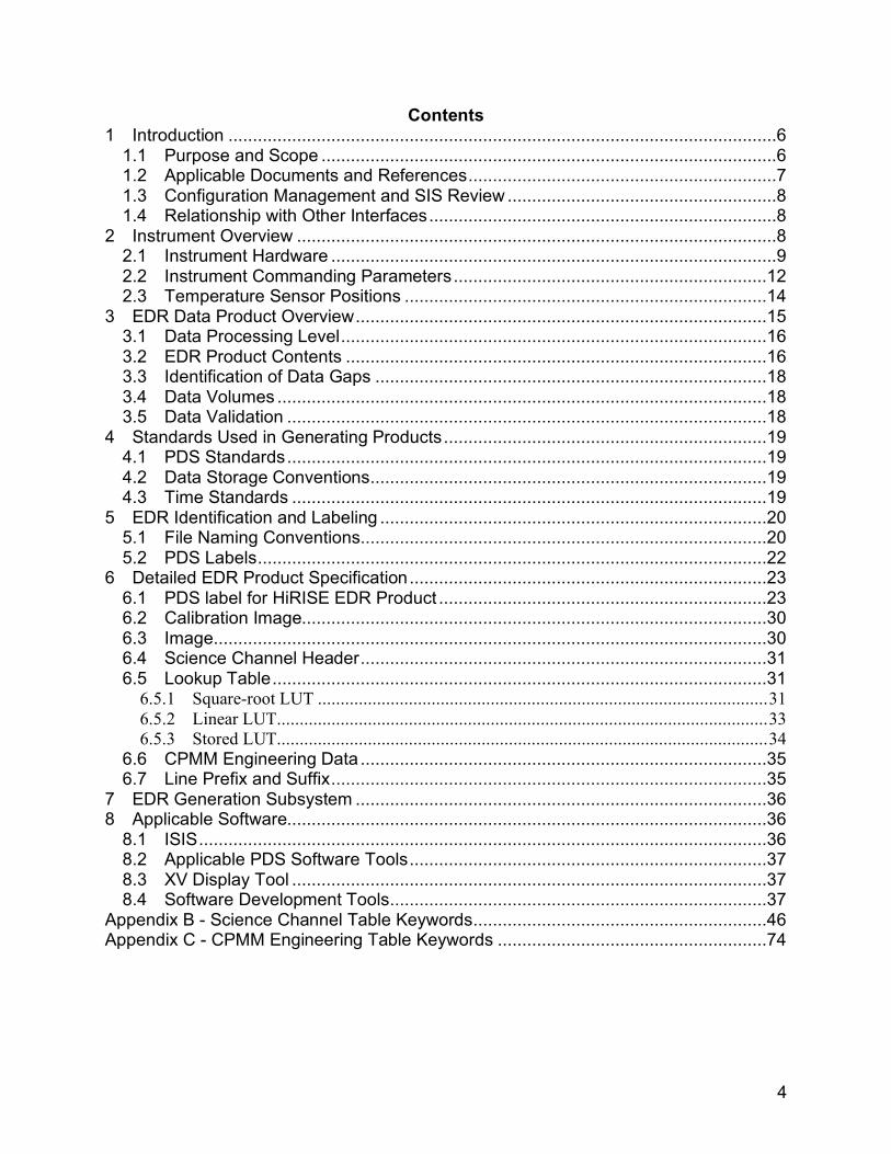
Contents 1 Introduction ................................................................................................................6
1.1 Purpose and Scope .............................................................................................6 1.2 Applicable Documents and References...............................................................7 1.3 Configuration Management and SIS Review .......................................................8 1.4 Relationship with Other Interfaces.......................................................................8
2 Instrument Overview ..................................................................................................8 2.1 Instrument Hardware ...........................................................................................9 2.2 Instrument Commanding Parameters................................................................12 2.3 Temperature Sensor Positions ..........................................................................14
3 EDR Data Product Overview....................................................................................15 3.1 Data Processing Level.......................................................................................16 3.2 EDR Product Contents ......................................................................................16 3.3 Identification of Data Gaps ................................................................................18 3.4 Data Volumes ....................................................................................................18 3.5 Data Validation ..................................................................................................18
4 Standards Used in Generating Products..................................................................19 4.1 PDS Standards..................................................................................................19 4.2 Data Storage Conventions.................................................................................19 4.3 Time Standards .................................................................................................19
5 EDR Identification and Labeling ...............................................................................20 5.1 File Naming Conventions...................................................................................20 5.2 PDS Labels........................................................................................................22
6 Detailed EDR Product Specification.........................................................................23 6.1 PDS label for HiRISE EDR Product ...................................................................23 6.2 Calibration Image...............................................................................................30 6.3 Image.................................................................................................................30 6.4 Science Channel Header...................................................................................31 6.5 Lookup Table.....................................................................................................31
6.5.1 Square-root LUT ...................................................................................................31 6.5.2 Linear LUT............................................................................................................33 6.5.3 Stored LUT............................................................................................................34
6.6 CPMM Engineering Data ...................................................................................35 6.7 Line Prefix and Suffix.........................................................................................35
7 EDR Generation Subsystem ....................................................................................36 8 Applicable Software..................................................................................................36
8.1 ISIS....................................................................................................................36 8.2 Applicable PDS Software Tools.........................................................................37 8.3 XV Display Tool .................................................................................................37 8.4 Software Development Tools.............................................................................37
Appendix B - Science Channel Table Keywords............................................................46 Appendix C - CPMM Engineering Table Keywords .......................................................74

5
ACRONYMS AND ABBREVIATIONS ATLO Assembly, Test, and Launch Operations A/D Analog to Digital CCD Charge Couple Device CCSDS Consultative Committee for Space Data Systems CFDP CCSDS File Delivery Protocol CPMM CCD Processing and Memory Module DN Density Number EDR Experimental Data Record EEPROM Erasable Electronic Programmable Read-only Memory FELICS Fast and Efficient Lossless Image Compression System FPGA Field Programmable Gate Array FOV Field of View HiRISE High Resolution Imaging Science Experiment HiROC HiRISE Operations Center IFOV Instantaneous Field of View JPL Jet Propulsion Laboratory LUT Lookup Table MRO Mars Reconnaissance Orbiter MSB Most Significant Byte ODL Object Descriptor Language PDS Planetary Data System PSF Point Spread Function RDR Reduced Data Record RSDS Raw Science Data Server (located at JPL) SCLK Spacecraft Clock Count SIS Software Interface Specification SNR Signal to Noise Ratio SPROM Serial Programmable Read-Only Memory SRAM Static Random Access Memory SSR Solid State Recorder (digital storage medium on spacecraft) TDI Time Delay Integration

6
1 Introduction
1.1 Purpose and Scope The High Resolution Imaging Science Experiment (HiRISE) is one of the remote sensing instruments on the Mars Reconnaissance Orbiter (MRO) spacecraft that will acquire orbital observations during its two earth-year primary mapping phase. MRO was launched in August 2005 and is schedule to arrive at Mars in March 2006. Following orbit insertion the spacecraft will begin an aerobraking period to achieve a 255 x 320 kilometer near-polar orbit suitable for the systematic science mapping starting in November 2006. HiRISE will achieve unprecedented high-resolution imaging of the Mars surface of about 30-cm/pixel sampling. One of the responsibilities of the HiRISE Science Team is to create an archive of science observation data products created during the course of the mission. The purpose of this Software Interface Specification (SIS) is to provide a description of the Experimental Data Record (EDR) products provided by the HiRISE Science team. The SIS is intended to provide enough information to enable users to read and understand the EDR products. The users for whom this SIS is intended are software developers, engineers, and scientists interested in accessing and using these products. The SIS also provides a specification of the products to be delivered to the Planetary Data System (PDS). The SIS describes how the HiRISE team processes, formats, labels, and uniquely identifies the EDR products. The document describes standards used in generating the products and software that may be used to access the products. The data product structure and organization are described in sufficient detail to enable a user to develop software for reading the EDR products. Finally, examples of the product labels are provided. EDR products are the permanent record of the imaging acquired by the HiRISE instrument and successfully transmitted back to Earth. An EDR contains raw image data, observational-related engineering data, and information about the instrument commanding parameters used to acquire the image. The EDR products are used by the HiRISE team to create derived products that are radiometrically calibrated and geometrically processed to create map products associating a pixel to a latitude and longitude coordinate on the Mars surface. These derived products are described in the HiRISE Reduced Data Record (RDR) SIS. Scientists and engineers can use the EDR products when there is a need to work with the original raw science observation data. Typical uses for the EDR products may involve investigations to better understand the instrument’s radiometric and optical performance, to improve the calibration of the instrument, or to apply advanced image processing methods for creating derived products tailored to their needs.

7
1.2 Applicable Documents and References The EDR Product SIS is responsive to the following MRO project documents:
1. Mars Exploration Program Data Management Plan, R. E. Arvidson and S. Slavney, Rev. 2, Nov. 2, 2000.
2. Mars Reconnaissance Orbiter Project Data Archive Generation, Validation and Transfer Plan, R. E. Arvidson, S. Noland and S. Slavney, March, 2005.
3. Mars Reconnaissance Orbiter (MRO) High Resolution Imaging Science Experiment Operations Plan, Alfred McEwen, Eric Eliason and Candice Hansen, Version 3.0, February 7, 2005.
4. HiRISE Users Manual (Command and Telemetry Handbook), Ball Aerospace & Technologies Corporation, Version 1.8, April 5, 2005.
This SIS is also consistent with the following Planetary Data System (PDS) documents: 5. Planetary Data System Data Preparation Workbook, Version 3.1, JPL D-7669,
Part 1, February 1, 1995. 6. Planetary Data System Data Standards Reference, Version 3.6, JPL D-7669,
Part 2, August 1, 2003. 7. Planetary Science Data Dictionary Document, JPL D-7116, Rev. E, August 28,
2002. Additional References:
8. McEwen, M., C. Hansen, N. Bridges, W.A. Delamere, E. Eliason, J. Grant, V. Gulick, K. Herkenhoff, L. Keszthelyi, R. Kirk, M. Mellon, P. Smith, S. Squyres, N. Thomas, and C. Weitz, MRO's High Resolution Imaging Science Experiment (HiRISE) Science Expectations, Proceedings 6th Annual International Mars Conference, July 20-25, 2003, Pasadena, CA.
9. Delamere, A., I. Becker, J. Bergstrom, J. Burkepile, J. Day, D. Dorn, D. Gallagher, C. Hamp, J. Lasco, B. Meiers, A. Sievers, S. Streetman, S. Tarr, M. Tommeraasen, P. Volmer, MRO High Resolution Imaging Science Experiment (HiRISE): Instrument Development, Proceedings 6th Annual International Mars Conference, July 20-25, 2003, Pasadena, CA.
10. Howard, P. and J. Vitter, Fast and Efficient Lossless Image Compression, Proceedings IEEE Computer Society/NASA/CESDIS Data Compression Conference, Snowbird, Utah, March 30-April 1, 1993, pages 351-360
11. Eliason E., C. Hansen, A. McEwen, W. Delamere, N. Bridges, J. Grant, V. Gulick, K. Herkenhoff, L. Keszthelyi, R. Kirk, M. Mellon, P. Smith, S. Squyres, N. Thomas, and C. Weitz, Operation Of MRO’s High Resolution Imaging Science Experiment (HiRISE): Maximizing Science Participation, Proceedings 6th Annual International Mars Conference, July 20-25, 2003, Pasadena, CA.

8
1.3 Configuration Management and SIS Review The HiRISE Software Development Team controls this document. Requests for changes to the scope and contents of this document must be made to the HiRISE Ground Data System Manager. An Engineering change request will be evaluated against its impact on the HiRISE ground data processing system before acceptance. The EDR SIS has been through the formal peer review process required by the PDS and has been determined to meet PDS data product standards. Members from the PDS Geosciences, Imaging, and Engineering Nodes were on the review panel, held on August 24, 2004, with additional members from the Planetary Science community. Results of the peer review are available at the Geosciences Node website (http://wufs.wustl.edu/missions/mro/hirise/edr_review).
1.4 Relationship with Other Interfaces EDR products capture the raw science data as observed by HiRISE. Thus changes in the organization and content of the output of the instrument impact the SIS and the software that generates the EDR products. The source for the raw data used in creating the EDR products is the Jet Propulsion Laboratory's Raw Science Data Server (RSDS) supporting the MRO Project. Changes in the format and contents of the raw data files as described in the Product Telemetry SIS will additionally impact the generation of the EDR products. High-level HiRISE imaging products and the processing systems that generate these products are potentially impacted by any changes to the SIS.
2 Instrument Overview The HiRISE camera is a "pushbroom" imaging system featuring a 0.5 m aperture telescope with a 12 m focal length and 14 CCD detectors capable of generating images of up to 20,264 cross-scan observation pixels (exclusive of overlap pixels) and 65,000 unbinned scan lines (Table 2.0). The HiRISE instrument capabilities include the acquisition of: (1) observations of the Mars surface from orbit with a ground sampling dimension between 25 and 32 cm/pixel, depending on the orbital altitude, along with an intrinsic point spread function of 1.4 pixels (full width at half maximum assuming no spacecraft jitter) and high signal-to-noise ratio (SNR), (2) high-resolution topographic data from stereo observations with a vertical precision of ~0.2 m over areas of ~5x5 pixels (~1.5 m), and (3) observations in 3 colors with high radiometric fidelity. A key instrument design feature includes Charge Couple Device (CCD) detectors with up to 128 lines of Time Delay and Integration (TDI) to create high (>100:1) SNR in the Red filter bandpass anywhere on Mars. At the nominal 300 km MRO orbital altitude the instrument can acquire image swaths of approximately 6 kilometers cross-orbit and 20 kilometers along-orbit.

9
Table 2.0 - HiRISE Instrument Performance
Parameter Performance Comments Ground Sample Distance (GSD)
30 cm/pixel From 300 km altitude
Telescope Aperture 0.5 m, f/24 For resolution and Signal to Noise ratio
Spectral range 500 nm (400 to 600 nm) 700 nm (550 to 850 nm) 900 nm (800 to 1100 nm)
Blue-Green Red Near-infrared
Blue-Green Typically 100:1 Red Typically 200:1
SNR
NIR Typically 100:1
Achieved with Time Delay Integration, backside thinned CCDs, and 50 cm aperture
Red > 6 km From 300 km altitude Swath Width Blue-Green & NIR > 1.2 km From 300 km altitude Swath length > 2× swath width Along track Data Precision 14 bit Analog to Digital
Converters 12 to 13 usable bits
Real-time 14 to 8 bit Look-up table 1, 2, 3, 4, 8 16 Pixel binning, increases areal coverage
Data Compression
Lossless compression on Solid State Recorder (8-bit only)
~ 2:1 compression
Camera memory 28 Gbits All channels Number of pixels across swath
20,264 Red 4,048 Green and NIR
From swath width and pixel scale
TDI line time ≥74 µsec Set to match ground track speed CCD read noise < 50 electrons rms at 22°C Achieve SNR at low signal levels FOV 1.14° × 0.18° IFOV 1 × 1 µrad Detector angular subtense Relative Radiometry < 1 % pixel to pixel Absolute 20%
2.1 Instrument Hardware The HiRISE design (Figure 2.1.a) is an all-reflective three mirror astigmatic telescope with lightweight Zerodur optics and a graphite-composite structure. The Cassegrain design with relay optic and two fold mirrors is optimized for diffraction-limited performance. Filters in front of the detector arrays provide images in the three wavelengths: red, blue-green, and near-infrared. The 14 CCDs are staggered to provide full-swath coverage without gaps. Both the blue-green and near-infrared bands have two CCD arrays each to give a total swath width of 4,048 non-overlapping pixels. The red filter CCD detectors provide a swath width of 20,264 non-overlapping pixels.

10
The HiRISE focal plane system consists of 14 independently commanded CCD arrays housed in a focal plane substrate of aluminum-graphite composite material collocated with CCD Processing and Memory Modules (CPMM). Each CCD has 2048 pixels (12x12 µm) in the cross-scan direction and 128 TDI elements (stages) in the along-orbit direction. The 14 staggered CCDs overlap by 48 pixels at each end (except the outside ends) as shown in Figure 2.1b. Using TDI increases the exposure time by integrating the signal of up to 128 detectors passing over the same point on the planet surface allowing both very high resolution and high SNR. TDI can be commanded for all CCD detectors including the color filter CCDs. As the spacecraft moves above the surface of Mars, TDI integrates the signal as it passes across the CCD detector by shifting the accumulated signal into the next row of the CCD at the same rate as the scene moves through the array. The line rate of ~13,000 lines/second corresponds to a line time of 76 microseconds for 250 km altitude. The imager can use 8, 32, 64, or 128 TDI stages to match scene radiance with CCD sensitivity. Spacecraft orientation in yaw will compensate for effects of planet rotation. Images with higher SNR and lower resolution can be achieved by binning the signal from adjacent lines and pixels within the CCD up to a maximum binning of 16x16 pixels.
Tertiary Mirror
Secondary Mirror
Secondary Mirror Baffle
Primary Mirror
Primary Mirror Baffle
FocusMechanism
2nd FoldMirror
1st Fold Mirror
Filters
FocalPlane
Focal PlaneElectronics
Tertiary Mirror
Secondary Mirror
Secondary Mirror Baffle
Primary Mirror
Primary Mirror Baffle
FocusMechanism
2nd FoldMirror
1st Fold Mirror
Filters
FocalPlane
Focal PlaneElectronics
Figure 2.1.a - Camera optical design.

11
The CCD Processing and Memory Module (CPMM) electronics minimizes the number of active and passive components that contribute to noise. The analog signal processing chain between the CCD output amplifier and the 80 Mega Samples per Second 14 bit (pixel value range 0-16,383) Analog to Digital (A/D) converters have been designed so that they add less noise than the CCD while being radiation tolerant and reasonably low power. Each of the 14 CPMM's uses a radiation-hardened Xilinx Virtex 300E Field Programmable Gate Array (FPGA) to perform the control, signal processing, lookup table compression, data storage, maintenance, and external Input/Output. The FPGA is Static Random Access Memory (SRAM) based using a Flash Serial Programmable Read Only Memory (SPROM) for configuration upon power-up. The SPROM and FPGA are reconfigurable so design changes can be applied. The number in the CCD name (shown in figure 2.1.b) and CPMM number do not necessarily match. The relationship is expressed in Table 2.1.c
Table 2.1.c - CCD/CPMM Relationship
CCD Name CPMM Number RED0 0 RED1 1 RED2 2 RED3 3 RED4 5 RED5 8 RED6 10
Blue-Green & NIR
Active Length of Red Array
CCD Active Area
24.6 mm
Active Length of a DCAFPA Substrate
DCA Substrate
14 CCDs (2048 x 128 pixels): 10 CCDs Form Red Channel (20,264 pixels) 2 CCDs Form Blue-Green Channel (4048 pixels) 2 CCDs Form NIR Channel (4048 pixels) HiRISE power supply enables simultaneous operation of at least 10 CCDs. Figure 2.1.b - Focal Plane Array
RED0 RED1
RED2 RED3
RED4 RED5
RED6 RED7
RED8 RED9
IR10 IR11
BG12 BG13

12
RED7 11 RED8 12 RED9 13 IR10 6 IR11 7 BG12 4 BG13 9
2.2 Instrument Commanding Parameters The 14 CCD detector arrays can be independently commanded offering flexibility for how a HiRISE image observation can be acquired. Power requirements on the HiRISE instrument allow all 14 CCD detectors to be simultaneously operated. A summary of the commanding parameters is shown in Table 2.2. Not all 14 CCDs need to simultaneously operate to acquire an observation. Depending on the type of observation the color filter CCDs may not need to participate in the observation, for example if color data is not required to satisfy the observational intent. If a narrower cross-orbit swath is desired, the observation may have fewer red-filter CCDs operating. Several data compression methods can be employed to optimize data return. The first compression method uses pixel binning where adjacent pixels in an image are summed equally in the cross-scan and down-scan pixel dimensions (permitted values: unbinned, 2, 3, 4, 8, 16). Binning reduces data volume and increases the pixel SNR, a useful option in low illumination viewing conditions. Different binning modes can be specified for each CCD. A typical HiRISE red-filter observation might acquire unbinned image data for the CCDs in the central portion of the observation where the primary target of interest is located while the peripheral CCDs may be binned to create a context for the primary target. With this flexibility, HiRISE operations can make optimal use of the available data-return volume. A second data compression method converts the 14-bit data stream (16-bit/pixel storage) to 8-bit pixels thereby reducing the returned data volume of an observation by half. The conversion to 8-bit pixels employs look-up tables (LUT) translating the 14-bit values to 8-bit. There are 28 onboard command-selectable LUTs available. Additionally, an "on-the-fly" LUT can be defined using commanded instrument parameters. Linear and non-linear (square root) methods can be used to define the LUT (see section 6.5 for additional details). A third data compression method employs a lossless data compression system not part of the HiRISE instrument hardware. MRO's Solid State Recorder (SSR) receives and stores data from the HiRISE instrument. A Fast and Efficient Lossless Image Compression System (FELICS) FPGA board is located on the interface between the HiRISE instrument and the SSR to enable compression of the image data before storage on the SSR and subsequent data transmission back to Earth. The FELICS algorithm is expected to offer compression ratios ranging 1.7:1 to 2.0:1. FELICS

13
compression is applied only to 8-bit pixel data thereby requiring the LUT translation to be additionally used. Additional commanding parameters specify the number of post-binned image lines, TDI stages, and the line exposure duration. The number of post-binned image lines defines the areal extent of an observation in the down-orbit direction while the number of commanded CCDs defines the cross-orbit areal extent. The number of lines is limited by the instrument buffer space available for storing image data (63,000 unbinned lines for 14-bit data, 126,000 lines for 8-bit data). The number of TDI stages specifies how many TDI down-scan sensors to integrate while acquiring an image observation (permitted values are 8, 32, 64, and 128). The binning mode, viewing conditions, and spacecraft jitter are considerations when determining the optimal number of TDI stages. TDI stages improperly selected may cause image saturation or images with poor SNR. High-albedo targets acquired under bright lighting conditions may cause image saturation for 128 TDI stages. Conversely, observations with low lighting conditions, such as polar observations, might use a larger number of TDI stages to increase the SNR. If large pixel binning were commanded then the number of TDI stages would be reduced to prevent image saturation. Finally, the number of TDI stages impacts the effect of spacecraft jitter on the point-spread function (PSF) of the image pixels. Effects of spacecraft jitter are reduced for fewer TDI stages but also reduce SNR. The line time specifies the time between the generation of successive lines. The adjustment of this parameter matches the TDI readout with the boresight groundtrack velocity. Line time is the same for all CCDs for a given observation. Table 2.2 - HiRISE Observation Commands
Command Option
Values or Range Comments
Pixel Binning 1 (no binning), 2, 3, 4, 8, 16
Independently commanded for each CCD. Used to reduce data volume and increases pixel SNR for low illumination observations (at the sacrifice of resolution).
14-to-8bit Pixel Conversion
28 onboard LUTs or "on-the-fly" LUTs
LUTs are specified at the CCD level. On-the-fly LUTS can be created by ground commanding using linear and square root LUT definitions. Predefined LUTs can additionally be specified. (See section 6.5)
FELICS Compression
ON or OFF FELICS compression works only on 8-bit pixel data. Lossless compression ratios are expected to range from 1.7:1 to 2.0:1.
Number of Lines
1 to ~65,000 (for unbinned data)
Number of post-binned lines to gather for each CCD.
Number of TDI stages
8, 32, 64, 128 Number of TDI stages for each CCD.

14
Line Time 74 microseconds + D/16 nanoseconds, where D = 0 to 4194303)
Time between the generation of successive unbinned lines. The adjustment of this parameter matches the boresight groundtrack velocity. The value is the same for all CCDs for a given observation.
2.3 Temperature Sensor Positions The positions of the 35 temperature sensors on the HiRISE instrument are shown in Figure 2.3. Table 2.3 provides the sensor number and the corresponding PDS keyword as described in section 6.1.
+X
+Z
+Y
1
2
3
4
5
6
Note: Operational temperature sensors 7, 8, 11, 13, 14, 20 and 3 0 are not shown due to structure removed for clarity.
9
10
12
15
16
17
18
19
21
22
23
24
25
26
27
2829
31
Figure 2.3 Positions of temperature sensors on HiRISE
+X
+Z
+Y
1
2
3
4
5
6
Note: Operational temperature sensors 7, 8, 11, 13, 14, 20 and 3 0 are not shown due to structure removed for clarity.
9
10
12
15
16
17
18
19
21
22
23
24
25
26
27
2829
31
Figure 2.3 Positions of temperature sensors on HiRISE
Table 2.3 - Temperature Sensor number shown in Figure 2.3 and corresponding PDS Keyword used to identify the sensor Sensor Number PDS Keyword
1 MRO:OPT_BNCH_FLEXURE_TEMPERATURE 2 MRO:OPT_BNCH_MIRROR_TEMPERATURE 3 MRO:OPT_BNCH_FOLD_FLAT_TEMPERATURE 4 MRO:OPT_BNCH_FPA_TEMPERATURE 5 MRO:OPT_BNCH_FPE_TEMPERATURE 6 MRO:OPT_BNCH_LIVING_RM_TEMPERATURE 7 MRO:OPT_BNCH_BOX_BEAM_TEMPERATURE 8 MRO:OPT_BNCH_COVER_TEMPERATURE 9 MRO:MS_TRUSS_LEG_0_A_TEMPERATURE

15
10 MRO:MS_TRUSS_LEG_0_B_TEMPERATURE 11 MRO:MS_TRUSS_LEG_120_A_TEMPERATURE 12 MRO:MS_TRUSS_LEG_120_B_TEMPERATURE 13 MRO:MS_TRUSS_LEG_240_A_TEMPERATURE 14 MRO:MS_TRUSS_LEG_240_B_TEMPERATURE 15 MRO:SEC_MIRROR_MTR_RNG_TEMPERATURE 16 MRO:PRIMARY_MIRROR_MNT_TEMPERATURE 17 MRO:PRIMARY_MIRROR_TEMPERATURE 18 MRO:PRIMARY_MIRROR_BAF_TEMPERATURE 19 MRO:BARREL_BAFFLE_TEMPERATURE 20 MRO:SPIDER_LEG_30_TEMPERATURE 21 MRO:SPIDER_LEG_150_TEMPERATURE 22 MRO:SPIDER_LEG_270_TEMPERATURE 23 MRO:SEC_MIRROR_TEMPERATURE 24 MRO:SEC_MIRROR_BAFFLE_TEMPERATURE 25 MRO:FIELD_STOP_TEMPERATURE 26 MRO:SUN_SHADE_TEMPERATURE 27 MRO:FPA_POSITIVE_Y_TEMPERATURE 28 MRO:FPA_NEGATIVE_Y_TEMPERATURE 29 MRO:FPE_TEMPERATURE 30 MRO:IEA_TEMPERATURE 31 MRO:FOCUS_MOTOR_TEMPERATURE 32 MRO:INST_CONT_BOARD_TEMPERATURE 33 MRO:MECH_TLM_BOARD_TEMPERATURE 34 MRO:CPMM_PWS_BOARD_TEMPERATURE 35 MRO:IE_PWS_BOARD_TEMPERATURE
3 EDR Data Product Overview The HiRISE EDR products are produced at the HiRISE Operations Center (HiROC) located at the Lunar and Planetary Laboratory, University of Arizona. The EDR is used in subsequent processing to create higher-level products that are radiometrically and geometrically processed. The HiRISE data are returned to Earth through the Deep Space Network then transmitted to JPL where they are organized and stored at the MRO Operations Center. The MRO Operations Center will convert the packet telemetry data to CCSDS (Consultative Committee for Space Data Systems) File Delivery Protocol format (CFDP). The CFDP files are then transmitted to HiROC for processing and generation of the EDR products. The EDR products are produced as labeled products conforming to Planetary Data System (PDS) Standards. The EDR products are made available to HiRISE Science team members, MRO Project Investigators, and delivered to the PDS for permanent archival according to the delivery schedules specified in the MRO Data Archive and Transfer Plan. EDR products are the permanent record of the HiRISE raw image data collection. An EDR contains unprocessed image data (except as noted below), ancillary engineering data, and information about the instrument commanding used to acquire the image. An EDR image has the inherent properties of raw and unprocessed data. Data gaps may exist in an EDR primarily due to telemetry communication problems between Mars and Earth. The image pixel values are raw counts not yet radiometrically corrected. No

16
geometric processing has been applied to the data to correct for optical distortion or viewing geometry. The HiRISE Reduced Data Record (RDR) products (described in the HiRISE RDR SIS) have undergone radiometric correction and geometric processing. RDR products are intended to be the more useful product for science data analysis. EDR products are organized at the channel level with two EDR products created for each operating CCD. The HiRISE instrument readout electronics divides the output of a CCD detector into two data channels. CCD pixels 0-1023 are passed to the first channel and pixels 1024-2047 to the second channel. The pixel output of the second channel of a CCD is electronically read out in reverse order causing the pixels to be mirrored so that CCD pixel 1024 is located in the byte position 2047. In the EDR generation process the pixel data of channel 1 is reordered (mirrored) to provide a consistent viewing orientation. With the data organized at the channel level, a single HiRISE observation will have as many as 28 (assuming all 14 CCDs were operating) individual EDR products each stored in a separate file. The format of the EDR data products is nearly identical to the original form of the data stream as produced by the instrument. Some processing was applied to the data for (1) FELICS decompressing an image (if the data were optionally compressed on the spacecraft), (2) identifying and filling gaps with "no-data" values, (3) mirroring the pixel order of an image line for data read out in reverse order, and (4) adding a PDS label to the beginning of the file.
3.1 Data Processing Level The EDR products are processed to NASA data processing level-0. (This corresponds to level 2 for the "Committee on Data Management and Computation" (CODMAC) data level numbering system). NASA level-0 products contain time-ordered raw instrument science data at full resolution with duplicate data removed and transmission anomalies identified and corrected whenever possible.
3.2 EDR Product Contents An EDR is identified and described with PDS-labeling conventions (see section 5.2) with a PDS label located at the beginning of the file. Following the PDS label is the instrument data stream organized as objects each described by keywords in the PDS label area. The data objects store the raw image data and ancillary data needed to understand and process the image. Figure 3.2 illustrates the contents and organization of the EDR. The data objects contained in the EDR product were created by the HiRISE instrument flight software and remain in the original format except as noted in the SIS. The objects, describing various parts of the data stream, are summarized here. Detailed descriptions and formats are provided in section 6. “Pointer” keywords in the PDS label, identified with a carat (^) as the first character, locate the objects in the file (see section 5). The SCIENCE_CHANNEL_TABLE, LOOKUP_TABLE, and CPMM_ENGINEERING_TABLE objects contain metadata providing commanding, engineering, and instrument operating information related to the observation. The

17
LINE_PREFIX_TABLE and LINE_SUFFIX_TABLE objects contain engineering and calibration data accompanying the observational data. The CALIBRATION_IMAGE contains image data useful for calibrating the instrument. The IMAGE object contains the observational image data. The GAP_TABLE locates gaps (missing data) in the observation.
PDS Label area Pointers to objects: ^SCIENCE_CHANNEL_TABLE = xxxx <BYTES> ^LOOKUP_TABLE = xxxx <BYTES> ^CPMM_ENGINEERING_TABLE = xxxx <BYTES> ^CALIBRATION_LINE_PREFIX_TABLE = xxxx <BYTES> ^CALIBRATION_LINE_SUFFIX_TABLE = xxxx <BYTES> ^CALIBRATION_IMAGE = xxxx <BYTES> ^LINE_PREFIX_TABLE = xxxx <BYTES> ^LINE_SUFFIX_TABLE = xxxx <BYTES> ^IMAGE = xxxx <BYTES> ^GAP_TABLE = xxxx <BYTES>
Science Channel Table (800 bytes)
CPMM Engineering Table (60 bytes)
Lookup Table (16,384 bytes)
Image Lines
Line Prefix
Figure 3.2 - The HiRISE EDR is made up of a PDS label, the calibration and observation images and their ancillary data areas.
Line Suffix
Calibration Image Lines
Calibration
Line Prefix
Calibration
Line Suffix
Gap Table

18
3.3 Identification of Data Gaps Gaps consisting of missing data in the observation data stream can occur whenever there is an interruption in the downlink communications systems between the MRO spacecraft and the MRO operations center at JPL. Data gaps in the HiRISE EDR products can be identified in two ways. First, the GAP_TABLE object identifies the data gap locations in the EDR products. The GAP_TABLE is a binary table of two columns that specify the starting and ending byte location of each gap. There is a row for each gap (see the PDS example label in section 6.1 for a label description of the GAP_TABLE). Additionally, gaps can be identified in the data by searching for consecutive bytes with the hexadecimal value “FF” (decimal 255). A gap is identified as any byte sequence containing more than four consecutive “FF” values. HiRISE 8-bit image pixels with the hexadecimal value “FF” will be a missing pixel. For 16-bit pixel data, the hexadecimal value “FFFF” identifies the pixel as missing. This is a reliable test because the HiRISE instrument can never create a “FF” 8-bit pixel or a “FFFF” 16-bit pixel.
3.4 Data Volumes The total data volume for the HiRISE EDR product dataset is expected to be significant. For the nominal mission the HiRISE downlink data allocation is 9.1 terabits based on the HiRISE instrument's 35% allocation of the total 26 terabit nominal mission return. The actual amount of HiRISE data returned may reach 17.5 terabits (35% of 50 terabits) due to possible increases in Deep Space Network 70 meter antenna coverage and expanded use of Ka band telemetry. With FELICS compression used for most HiRISE observations the uncompressed EDR data set could range up to 18.2 (nominal mission) or 35 terabits (with increased downlink).
3.5 Data Validation The MRO Data Archive Working Group (DARWG) will oversee data product validation and transfer of products to the PDS. The DARWG (made up of representatives from the MRO project, MRO Instrument Teams, and the PDS) will identify procedures and responsibilities for data validation. During operations, HiROC Targeting Specialists and the HiRISE Science Team will determine if an image has met its observational objectives. The team will verify the desired target has been properly observed. Images will be inspected for satisfactory viewing conditions and image statistics. An image that fails to meet its observational objectives may be re-observed at a later time. Verification that data products are in compliance with PDS standards is additionally a responsibility of the HiROC ground operations staff. PDS-created validation tools will be used whenever possible as part of the process. The PDS may choose to conduct additional independent data product verification as they receive data products.

19
For the first delivery the EDR dataset will go through a review before acceptance by PDS. The HiRISE Team and the PDS will convene a peer review panel to examine the dataset for completeness and conformance to the EDR product SIS.
4 Standards Used in Generating Products
4.1 PDS Standards The HiRISE EDR products comply with the PDS standards for file formats and labels; specifically using the PDS image and table object definitions.
4.2 Data Storage Conventions The HiRISE EDR products contain binary data. Image pixel values are stored as either unsigned 8-bit or unsigned16-bit pixel values depending on the operating mode of the instrument. The PDS label sections are stored as ASCII character strings conforming to the requirements defined in the PDS Standards Reference. The storage order is most significant byte (MSB) first. MSB ordering is the order used on the MRO spacecraft and the HiRISE instrument.
4.3 Time Standards Two time-related standards are used in HiRISE EDR PDS labels: Spacecraft clock; Coordinated Universal time (UTC). The spacecraft clock (SCLK) is the fundamental system on MRO for initiating spacecraft events (such as starting an observation for one of the instruments). The SCLK has a counting unit of 1/(216) seconds for each tick of its sub-seconds field. Thus there are 65,536 SCLK ticks per second (a time interval of 15.2588 microseconds). The HiRISE expose-time command initiated by the spacecraft contains both the SCLK seconds and sub-seconds fields of that future moment in time at which the HiRISE exposure should begin. The HiRISE software will compute and store the corresponding future instant (converting SCLK sub-seconds notation to that of the HiRISE notation) at which time the exposure should begin. The HiRISE flight software will then set a 50-millisecond exposure-start software timer. Each time the expose-start timer elapses (every 50 milliseconds), the HiRISE flight software will check the current HiRISE time against the time at which the exposure should begin, and will start the exposure the first time it sees that current HiRISE time is later in time than the exposure time. The HiRISE flight software will time-stamp the actual start of an exposure (placed in the science channel header) to within 50 milliseconds of the actual start of the exposure. This time stamp, as well as all the other time stamps which the HiRISE flight software produces, will all be in units of the HiRISE clock (i.e. with the sub-seconds field counting in units of 16 milliseconds).

20
HiROC ground data processing converts to SCLK units when computing the time at which various time-stamped HiRISE events occurred. The instrument sub-second field is converted back to the SCLK sub-second field and stored in the PDS labels. This conversion occurs in order to allow the SPICE NAIF toolkit (see http://pds-naif.jpl.nasa.gov/) to be used to process time fields. UTC times can be derived from the SCLK using the NAIF toolkit time routines and the SCLK kernel maintained by the MRO project.
5 EDR Identification and Labeling
5.1 File Naming Conventions The EDR product file names are constructed from the observation ID associated with each observation. The observation ID is the unique identification that tracks observations by the HiRISE ground processing system. The file name contains additional information that identifies the filter, CCD, and channel. There will be a unique file name for each EDR product produced by the mission. For calibration, ATLO (Assembly, Test and Launch Operations), and mission cruise observations (i.e. all pre-orbit phases) the observation ID is constructed from the observation time. For the Mars orbital mission phases, the observation ID is built from the orbit number and the observation's nominal target position. Table 5.1 describes the file naming convention for EDR products. Table 5.1 - EDR File Name Conventions
Mission Phase File Naming Convention Pre-launch Phases:
ppp_yyyyaaddThhmmss_ffff_c.IMG
Post-launch Phases:
ppp_oooooo_tttt_ffff_c.IMG
Where: Description ppp
Mission Phase: INT = Integration and Testing CAL = Calibration Observations ATL = ATLO Observations KSC = Kennedy Space Center Observations SVT = Sequence Verification Test LAU = Launch CRU = Cruise Observations APR = Mars Approach Observations AEB = Aerobraking Phase TRA = Transition Phase PSP = Primary Science Orbit

21
REL = Relay phase E01 = 1st Extended Mission Phase if needed Exx = Additional extended Missions if needed
Pre-launch Phases: yyyyaaddThhmmss
Time of observation (UTC): yyyy = year, aa = month, dd = day of month hh = hour, mm = minute, ss = second
Cruise Phase and Aerobraking phase
oooooo = Observation sequence identifier tttt = Observation identification within the observation sequence.
Post Aerobraking Phases: ooooo_tttt
oooooo = MRO orbit number tttt = Target code. The target code refers to the latitudinal position of the center of the planned observation relative to the start of orbit. The start of orbit is located at the equator on the descending side (night side) of the orbit. A target code of 0000 refers to the start of orbit. The target code increases in value along the orbit track ranging from 0000 to 3595. This convention allows the file name ordering to be time sequential. The first three digits refers to the number of whole degrees from the start of orbit, the fourth digit refers to the fractional degrees rounded to the nearest 0.5 degrees. Values greater that 3595 identify observations as off-Mars or special observations. Examples of target code: 0000 – planned observation at the equator on descending side of orbit. 0900 – planned observation at the south pole. 1800 – planned observation at the equator on the ascending side (day side) of the orbit. 2700 – planned observation at the north pole. Off-Mars and Special Observations Values: 4000 – Star Observation 4001 – Phobos Observation 4002 – Deimos Observation

22
4003 – Special Calibration Observation ffff
Filter/CCD designation: RED0-RED9 - Red filter CCDs IR10-IR11 – Near-Infrared filter CCDs BG12-BG13 – Blue-Green filter CCDs
C Channel number of CCD (0 or 1) Examples: ATL_20050321T121312_RED0_1.IMG ATLO observation, acquired on March 21, 2005, at 12:13:12, Red filter, CCD 0, Channel 1. PSP_09933_1005_BG12_0.IMG Primary Science Phase observation, orbit 9933, centered at 100.5 latitudinal degrees from start of orbit, Blue/Green Filter, CCD 12, Channel 0
5.2 PDS Labels The HiRISE EDR products have attached PDS labels identifying and describing the objects within a data file. The PDS label contains keywords for product identification, and storing and organizing ancillary data. The label also contains descriptive information needed to interpret or process the data objects in the file. PDS labels are written in Object Description Language (ODL) [9]. ODL statements have the form of "keyword = value". Each label statement is terminated with a carriage return character (ASCII 13) and a line feed character (ASCII 10) sequence allowing the label to be read by many operating systems. Pointer statements are used to indicate the location of data objects in the file: formatted as ^object = byte <bytes>, where the carat character (^) is followed by the name of the specific data object. The byte location value is the starting byte position for the data object within the file. The PDS numbers the first byte in a file as byte position 1. Following the object pointers, a set of identification and descriptive data elements give information about the dataset. These include identifiers for the data product, instrument, spacecraft and mission; information about the input data such as time and information about the producing institution. Information about the instrument operational conditions and operating modes are additionally provided. Finally, definitions of the data objects in the file are given. The IMAGE object definition contains information about the size, data type, and special pixel values of the image data.

23
6 Detailed EDR Product Specification
6.1 PDS label for HiRISE EDR Product An example PDS label is shown below. The definitions and implementation details for the keywords are tabulated in Appendix A. A PDS label will always occupy the first 32768 bytes of an EDR product. The label will be padded with blank characters at the end of the label area to fill the label size allocation. The fixed-length label area may be advantageous for applications that might want to bypass the PDS label area and directly access the HiRISE data observation. Some of the data object pointers in the EDR product label point to the same starting byte location and area in the file. There are two sets of objects that occupy the same data areas. The first set of objects is made up of the CALIBRATION_IMAGE, CALIBRATION_LINE_PREFIX_TABLE, and CALIBRATION_LINE_SUFFIX_TABLE objects. The second set is made up of the IMAGE, LINE_PREFIX_TABLE, and LINE_SUFFIX_TABLE objects. The method is employed to describe different components of the same observational data area. PDS keywords that begin with “MRO:” are identified as a “Local Data Dictionary” keyword. These keywords are unique to the HiRISE instrument and are not included in the PDS system-wide data dictionary. The PDS Geosciences Node maintains local Data Dictionary definitions for the MRO project. Example PDS Label: PDS_VERSION_ID = PDS3 /* File structure: */ /* This file contains an unstructured byte stream. */ /* The UNDEFINED RECORD_TYPE is used to meet PDS standards requirements. */ /* A label "record" is actually a single byte. */ RECORD_TYPE = UNDEFINED /* Locations of Data Objects in the file. */ /* >>> CAUTION <<< The first byte is location 1 (not 0)! */ LABEL_RECORDS = 32768 <BYTES> ^SCIENCE_CHANNEL_TABLE = 32769 <BYTES> ^LOOKUP_TABLE = 33569 <BYTES> ^CPMM_ENGINEERING_TABLE = 49953 <BYTES> ^CALIBRATION_LINE_PREFIX_TABLE = 50013 <BYTES> ^CALIBRATION_LINE_SUFFIX_TABLE = 50013 <BYTES> ^CALIBRATION_IMAGE = 50013 <BYTES> ^LINE_PREFIX_TABLE = 68955 <BYTES> ^LINE_SUFFIX_TABLE = 68955 <BYTES> ^IMAGE = 68955 <BYTES> ^GAP_TABLE = 355955 <BYTES> /* Identification information. */ DATA_SET_ID = "MRO-M-HIRISE-2-EDR-V1.0" DATA_SET_NAME = "MRO MARS HIGH RESOLUTION IMAGING SCIENCE EXPERIMENT EDR V1.0" PRODUCER_INSTITUTION_NAME = "UNIVERSITY OF ARIZONA"

24
PRODUCER_ID = "UA" PRODUCER_FULL_NAME = "ALFRED MCEWEN" OBSERVATION_ID = "CRU_000038_0000" MRO:COMMANDED_ID = "CRU_000038_0000" PRODUCT_ID = "CRU_000038_0000_RED4_0" PRODUCT_VERSION_ID = "1.0" SOURCE_FILE_NAME = "4A_01_2800980000_05_0_02.DAT" INSTRUMENT_HOST_NAME = "MARS RECONNAISSANCE ORBITER" INSTRUMENT_HOST_ID = "MRO" INSTRUMENT_NAME = "HIGH RESOLUTION IMAGING SCIENCE EXPERIMENT" INSTRUMENT_ID = "HIRISE" TARGET_NAME = "MARS" MISSION_PHASE_NAME = "CRUISE" ORBIT_NUMBER = 38 RATIONALE_DESC = "" SOFTWARE_NAME = "HiRISE_Observation v2.9.2 (2.43 2006/10/01 05:41:12)" FLIGHT_SOFTWARE_VERSION_ID = "IE_FSW_V4" /* Observation timing events. */ /* All xxx_COUNT values are for the MRO spacecraft clock (SCLK) */ /* in seconds:subseconds form. A subsecond tick = 15.2588 microseconds. */ /* All xxx_TIME values are referenced to UTC. */ /* To obtain the most accurate results from time values */ /* use the xxx_COUNT values with the latest SPICE kernels */ /* obtained from ftp://naif.jpl.nasa.gov/pub/naif/MRO/kernels. */ GROUP = TIME_PARAMETERS /* Time when power to the CPMM units was applied. */ MRO:ANALOG_POWER_START_TIME = 2006-01-18T16:37:47.635 MRO:ANALOG_POWER_START_COUNT = "822069486:20953" /* Time when the observation first started. */ MRO:OBSERVATION_START_TIME = 2006-01-18T16:38:09.640 MRO:OBSERVATION_START_COUNT = "822069508:21249" /* Time at the beginning of the first calibration image line. */ MRO:CALIBRATION_START_TIME = 2006-01-18T16:38:09.693 MRO:CALIBRATION_START_COUNT = "822069508:24747" /* Time at the beginning of the first target image line. */ START_TIME = 2006-01-18T16:38:09.703 SPACECRAFT_CLOCK_START_COUNT = "822069508:25387" /* Time at the end of the last target image line. */ STOP_TIME = 2006-01-18T16:38:09.851 SPACECRAFT_CLOCK_STOP_COUNT = "822069508:35087" /* Time when the CPMM readout started. */ MRO:READOUT_START_TIME = 2006-01-18T16:38:14.052 MRO:READOUT_START_COUNT = "822069512:48276" /* Time when this EDR product was created. */ PRODUCT_CREATION_TIME = 2007-03-14T17:43:41 END_GROUP = TIME_PARAMETERS /* Instrument settings. */ GROUP = INSTRUMENT_SETTING_PARAMETERS MRO:CPMM_NUMBER = 5 MRO:CHANNEL_NUMBER = 0 FILTER_NAME = "RED" CENTER_FILTER_WAVELENGTH = 700 <NANOMETERS> BANDWIDTH = 300 <NANOMETERS> MRO:SCAN_EXPOSURE_DURATION = 74.0000 <MICROSECONDS> MRO:LINE_EXPOSURE_DURATION = 296.0000 <MICROSECONDS> MRO:IMAGE_EXPOSURE_DURATION = 157768.0000 <MICROSECONDS>

25
MRO:DELTA_LINE_TIMER_COUNT = 0 MRO:POWERED_CPMM_FLAG = (ON, ON, ON, ON, ON, ON, ON, ON, ON, ON, ON, ON, ON, ON) MRO:BINNING = 4 MRO:TDI = 32 MRO:TRIM_LINES = 0 MRO:FOCUS_POSITION_COUNT = 2128 MRO:FELICS_COMPRESSION_FLAG = NO MRO:STIMULATION_LAMP_FLAG = (ON, ON, ON) MRO:HEATER_CONTROL_MODE = "CLOSED LOOP" MRO:HEATER_CONTROL_FLAG = (ON, ON, ON, ON, ON, ON, ON, ON, ON, ON, ON, ON, ON, ON) MRO:LOOKUP_TABLE_TYPE = "N/A" MRO:LOOKUP_TABLE_MINIMUM = -9998 MRO:LOOKUP_TABLE_MAXIMUM = -9998 MRO:LOOKUP_TABLE_MEDIAN = -9998 MRO:LOOKUP_TABLE_K_VALUE = -9998 MRO:LOOKUP_TABLE_NUMBER = -9998 /* This table provides a reverse mapping */ /* from 8-bit EDR image data back to 14-bit observation data. */ /* Each node of the map is the (lower, upper) inclusive range */ /* of the original 14-bit observation value */ /* that was translated to the 8-bit image value */ /* corresponding to the node number (first node = 0). */ /* Unused image values have the special range (-9998, -9998). */ /* A special ((0, 0)) map indicates that no LUT was applied. */ MRO:LOOKUP_CONVERSION_TABLE = ((0, 0)) /* Waveform sampling timing settings: (image, reset). */ MRO:ADC_TIMING_SETTINGS = (5, 4) /* Clocks timing locks: (first clock, second clock). */ MRO:DLL_LOCKED_FLAG = (YES, YES) MRO:DLL_LOCKED_ONCE_FLAG = (YES, YES) MRO:DLL_RESET_COUNT = 0 MRO:DLL_FREQUENCY_CORRECT_COUNT = 4 END_GROUP = INSTRUMENT_SETTING_PARAMETERS /* Temperature sensor readings at observation start. */ GROUP = TEMPERATURE_PARAMETERS MRO:OPT_BNCH_FLEXURE_TEMPERATURE = 9.8111 <C> MRO:OPT_BNCH_MIRROR_TEMPERATURE = 6.44491 <C> MRO:OPT_BNCH_FOLD_FLAT_TEMPERATURE = 9.29294 <C> MRO:OPT_BNCH_FPA_TEMPERATURE = 8.17062 <C> MRO:OPT_BNCH_FPE_TEMPERATURE = 6.96251 <C> MRO:OPT_BNCH_LIVING_RM_TEMPERATURE = 6.78997 <C> MRO:OPT_BNCH_BOX_BEAM_TEMPERATURE = 6.53117 <C> MRO:OPT_BNCH_COVER_TEMPERATURE = 11.4526 <C> MRO:FIELD_STOP_TEMPERATURE = 4.63415 <C> MRO:FPA_POSITIVE_Y_TEMPERATURE = 14.306 <C> MRO:FPA_NEGATIVE_Y_TEMPERATURE = 13.8734 <C> MRO:FPE_TEMPERATURE = 5.49626 <C> MRO:PRIMARY_MIRROR_MNT_TEMPERATURE = -16.1388 <C> MRO:PRIMARY_MIRROR_TEMPERATURE = -16.737 <C> MRO:PRIMARY_MIRROR_BAF_TEMPERATURE = -24.5009 <C> MRO:MS_TRUSS_LEG_0_A_TEMPERATURE = 20.1082 <C> MRO:MS_TRUSS_LEG_0_B_TEMPERATURE = 19.0681 <C> MRO:MS_TRUSS_LEG_120_A_TEMPERATURE = 19.3281 <C> MRO:MS_TRUSS_LEG_120_B_TEMPERATURE = 21.2354 <C> MRO:MS_TRUSS_LEG_240_A_TEMPERATURE = 21.669 <C> MRO:MS_TRUSS_LEG_240_B_TEMPERATURE = 23.491 <C> MRO:BARREL_BAFFLE_TEMPERATURE = -51.5257 <C> MRO:SUN_SHADE_TEMPERATURE = -49.2494 <C> MRO:SPIDER_LEG_30_TEMPERATURE = -4.0568 <C> MRO:SPIDER_LEG_150_TEMPERATURE = -4.22859 <C> MRO:SPIDER_LEG_270_TEMPERATURE = -0.876471 <C> MRO:SEC_MIRROR_MTR_RNG_TEMPERATURE = 16.5562 <C> MRO:SEC_MIRROR_TEMPERATURE = -14.7708 <C> MRO:SEC_MIRROR_BAFFLE_TEMPERATURE = -51.947 <C>

26
MRO:IEA_TEMPERATURE = 1.18861 <C> MRO:FOCUS_MOTOR_TEMPERATURE = 11.0205 <C> MRO:IE_PWS_BOARD_TEMPERATURE = -5.27036 <C> MRO:CPMM_PWS_BOARD_TEMPERATURE = -6.6371 <C> MRO:MECH_TLM_BOARD_TEMPERATURE = 6.51033 <C> MRO:INST_CONT_BOARD_TEMPERATURE = 4.30756 <C> END_GROUP = TEMPERATURE_PARAMETERS /* Instrument electrical power sensor readings. */ GROUP = POWER_PARAMETERS MRO:CPMM_POSITIVE_29_VOLTAGE = 29.1436 <V> MRO:CPMM_POSITIVE_29_CURRENT = 0.214706 <A> MRO:CPMM_POSITIVE_10_VOLTAGE = 9.02174 <V> MRO:CPMM_POSITIVE_10_CURRENT = 2.28682 <A> MRO:CPMM_POSITIVE_5_VOLTAGE = 5.02806 <V> MRO:CPMM_POSITIVE_5_CURRENT = 7.54798 <A> MRO:CPMM_POSITIVE_3_3_VOLTAGE = 3.31406 <V> MRO:CPMM_POSITIVE_3_3_CURRENT = 1.54077 <A> MRO:CPMM_POSITIVE_2_5_VOLTAGE = 2.50816 <V> MRO:CPMM_POSITIVE_2_5_CURRENT = 0.317777 <A> MRO:CPMM_POSITIVE_1_8_VOLTAGE = 1.812 <V> MRO:CPMM_POSITIVE_1_8_CURRENT = 4.04478 <A> MRO:CPMM_NEGATIVE_5_VOLTAGE = -5.04662 <V> MRO:CPMM_NEGATIVE_5_CURRENT = -0.678623 <A> MRO:HEATER_CURRENT = 0.809004 <A> MRO:INST_CONT_FPGA_POS_2_5_VOLTAGE = 2.5415 <V> MRO:MECH_TLM_FPGA_POS_2_5_VOLTAGE = 2.56592 <V> MRO:IEA_POSITIVE_28_VOLTAGE = 31.0371 <V> MRO:IEA_NEGATIVE_15_VOLTAGE = -15.3725 <V> MRO:IEA_POSITIVE_15_VOLTAGE = 15.2453 <V> MRO:IEA_POSITIVE_5_VOLTAGE = 5.07324 <V> END_GROUP = POWER_PARAMETERS /* Science Channel Header Observation Data Component description. */ OBJECT = SCIENCE_CHANNEL_TABLE INTERCHANGE_FORMAT = BINARY ROWS = 1 COLUMNS = 184 ROW_BYTES = 800 DESCRIPTION = "The Science Channel Table contains engineering fields describing the operating state and commanding of the HiRISE observation. For detailed information about the contents and organization of this observation data component, refer to the SCIENCE_CHANNEL_TABLE.FMT file." ^STRUCTURE = "SCIENCE_CHANNEL_TABLE.FMT" END_OBJECT = SCIENCE_CHANNEL_TABLE /* Lookup Table Observation Data Component description. */ OBJECT = LOOKUP_TABLE INTERCHANGE_FORMAT = BINARY ROWS = 16384 COLUMNS = 1 ROW_BYTES = 1 DESCRIPTION = "The Lookup Table (LUT) defines the translation of 14-bit input pixels to 8-bit output pixels. The table has one column and 16384 rows, one for each input DN value. The first entry of the table refers to the 8-bit output value for the input pixel value 0." OBJECT = COLUMN NAME = "Output Data Value" DATA_TYPE = MSB_UNSIGNED_INTEGER START_BYTE = 1 BYTES = 1 DESCRIPTION = "The rows represent the 8-bit output pixel value for each 14-bit input pixel. The first row contains the 8-bit pixel value corresponding to the input DN value of

27
0. Each subsequent row corresponds to the 8-bit output pixel of the next input DN value." END_OBJECT = COLUMN END_OBJECT = LOOKUP_TABLE /* CPMM Engineering Header Observation Data Component description. */ OBJECT = CPMM_ENGINEERING_TABLE INTERCHANGE_FORMAT = BINARY ROWS = 1 COLUMNS = 8 ROW_BYTES = 60 DESCRIPTION = "The CPMM Engineering Table contains engineering fields used by the CCD Processing and Memory Module (CPMM) in commanding the CCD during the observation. For detailed information about the contents and organization of this observation data component, refer to the CPMM_ENGINEERING_TABLE.FMT file." ^STRUCTURE = "CPMM_ENGINEERING_TABLE.FMT" END_OBJECT = CPMM_ENGINEERING_TABLE /* Calibration Image Data Line Prefix description. */ OBJECT = CALIBRATION_LINE_PREFIX_TABLE INTERCHANGE_FORMAT = BINARY ROWS = 33 COLUMNS = 2 ROW_BYTES = 30 ROW_SUFFIX_BYTES = 544 OBJECT = COLUMN NAME = "Line Identification" DATA_TYPE = MSB_UNSIGNED_INTEGER START_BYTE = 1 BYTES = 6 DESCRIPTION = "Line ID contains line synchronization pattern, channel number, and line counter." OBJECT = BIT_COLUMN NAME = "Line Synchronization Pattern" BIT_DATA_TYPE = MSB_UNSIGNED_INTEGER START_BIT = 1 BITS = 19 DESCRIPTION = "For valid lines this line synchronization pattern is 2#1111111100000000111#, for a corrupted or missing line the value is 2#1111111111111111111#." END_OBJECT = BIT_COLUMN OBJECT = BIT_COLUMN NAME = "Channel Number" BIT_DATA_TYPE = MSB_UNSIGNED_INTEGER START_BIT = 20 BITS = 5 DESCRIPTION = "Channel number associated with a line." END_OBJECT = BIT_COLUMN OBJECT = BIT_COLUMN NAME = "Line Counter" BIT_DATA_TYPE = MSB_UNSIGNED_INTEGER START_BIT = 25 BITS = 23 DESCRIPTION = "Line counter. First line = 0." END_OBJECT = BIT_COLUMN OBJECT = BIT_COLUMN NAME = "Bad Line" BIT_DATA_TYPE = MSB_UNSIGNED_INTEGER START_BIT = 48 BITS = 1 DESCRIPTION = "The bad line flag is set when the line was found to have a misplaced or corrupted line header. A line header that is lost in a data gap does not result in a bad line." END_OBJECT = BIT_COLUMN END_OBJECT = COLUMN OBJECT = COLUMN

28
NAME = "Buffer Pixels" DATA_TYPE = MSB_UNSIGNED_INTEGER START_BYTE = 7 BYTES = 24 ITEMS = 12 ITEM_BYTES = 2 DESCRIPTION = "The buffer pixels contain the value of empty pixels after going through the instrument electronics." END_OBJECT = COLUMN END_OBJECT = CALIBRATION_LINE_PREFIX_TABLE /* Calibration Image Data Line Suffix description. */ OBJECT = CALIBRATION_LINE_SUFFIX_TABLE INTERCHANGE_FORMAT = BINARY ROWS = 33 COLUMNS = 1 ROW_BYTES = 32 ROW_PREFIX_BYTES = 542 OBJECT = COLUMN NAME = "Dark Reference Pixels" DATA_TYPE = MSB_UNSIGNED_INTEGER START_BYTE = 1 BYTES = 32 ITEMS = 16 ITEM_BYTES = 2 DESCRIPTION = "Dark reference pixel values produced by masked detectors." END_OBJECT = COLUMN END_OBJECT = CALIBRATION_LINE_SUFFIX_TABLE /* Calibration Image Data Description. */ OBJECT = CALIBRATION_IMAGE LINES = 33 LINE_SAMPLES = 256 SAMPLE_BITS = 16 SAMPLE_BIT_MASK = 2#0011111111111111# SAMPLE_TYPE = MSB_UNSIGNED_INTEGER MISSING_CONSTANT = 16#FFFF# LINE_PREFIX_BYTES = 30 LINE_SUFFIX_BYTES = 32 DESCRIPTION = "The calibration image results from passing unexposed pixels through the instrument electronics. This records the instrument fixed noise signature that can be used to correct the observational data." END_OBJECT = CALIBRATION_IMAGE /* Image data line prefix description. */ OBJECT = LINE_PREFIX_TABLE INTERCHANGE_FORMAT = BINARY ROWS = 500 COLUMNS = 2 ROW_BYTES = 30 ROW_SUFFIX_BYTES = 544 OBJECT = COLUMN NAME = "Line Identification" DATA_TYPE = MSB_UNSIGNED_INTEGER START_BYTE = 1 BYTES = 6 DESCRIPTION = "Line ID contains line synchronization pattern, channel number, and line counter." OBJECT = BIT_COLUMN NAME = "Line Synchronization Pattern" BIT_DATA_TYPE = MSB_UNSIGNED_INTEGER START_BIT = 1 BITS = 19 DESCRIPTION = "For valid lines this line synchronization pattern is 2#1111111100000000111#, for a corrupted or

29
missing line the value is 2#1111111111111111111#." END_OBJECT = BIT_COLUMN OBJECT = BIT_COLUMN NAME = "Channel Number" BIT_DATA_TYPE = MSB_UNSIGNED_INTEGER START_BIT = 20 BITS = 5 DESCRIPTION = "Channel number associated with a line." END_OBJECT = BIT_COLUMN OBJECT = BIT_COLUMN NAME = "Line Counter" BIT_DATA_TYPE = MSB_UNSIGNED_INTEGER START_BIT = 25 BITS = 23 DESCRIPTION = "Line counter. First line = 33." END_OBJECT = BIT_COLUMN OBJECT = BIT_COLUMN NAME = "Bad Line" BIT_DATA_TYPE = MSB_UNSIGNED_INTEGER START_BIT = 48 BITS = 1 DESCRIPTION = "The bad line flag is set when the line was found to have a misplaced or corrupted line header. A line header that is lost in a data gap does not result in a bad line." END_OBJECT = BIT_COLUMN END_OBJECT = COLUMN OBJECT = COLUMN NAME = "Buffer Pixels" DATA_TYPE = MSB_UNSIGNED_INTEGER START_BYTE = 7 BYTES = 24 ITEMS = 12 ITEM_BYTES = 2 DESCRIPTION = "The buffer pixels contain the value of empty pixels after going through the instrument electronics." END_OBJECT = COLUMN END_OBJECT = LINE_PREFIX_TABLE /* Image data line suffix description. */ OBJECT = LINE_SUFFIX_TABLE INTERCHANGE_FORMAT = BINARY ROWS = 500 COLUMNS = 1 ROW_BYTES = 32 ROW_PREFIX_BYTES = 542 OBJECT = COLUMN NAME = "Dark Reference Pixels" DATA_TYPE = MSB_UNSIGNED_INTEGER START_BYTE = 1 BYTES = 32 ITEMS = 16 ITEM_BYTES = 2 DESCRIPTION = "Dark reference pixel values produced by masked detectors." END_OBJECT = COLUMN END_OBJECT = LINE_SUFFIX_TABLE /* Image data description. */ OBJECT = IMAGE LINES = 500 LINE_SAMPLES = 256 SAMPLE_BITS = 16 SAMPLE_BIT_MASK = 2#0011111111111111# SAMPLE_TYPE = MSB_UNSIGNED_INTEGER MISSING_CONSTANT = 16#FFFF# LINE_PREFIX_BYTES = 30 LINE_SUFFIX_BYTES = 32 DESCRIPTION = "Observation image data."

30
END_OBJECT = IMAGE /* Gap Table description. */ OBJECT = GAP_TABLE INTERCHANGE_FORMAT = BINARY ROWS = 0 COLUMNS = 2 ROW_BYTES = 8 DESCRIPTION = "The Gap Table identifies the location of gap byte value (0xFF) segments in the file as a set of [start, end) range pairs." OBJECT = COLUMN NAME = "Range Start" DATA_TYPE = MSB_UNSIGNED_INTEGER START_BYTE = 1 BYTES = 4 DESCRIPTION = "The byte offset (0-based) from the beginning of the file to the start byte (inclusive) of the gap segment." END_OBJECT = COLUMN OBJECT = COLUMN NAME = "Range End" DATA_TYPE = MSB_UNSIGNED_INTEGER START_BYTE = 5 BYTES = 4 DESCRIPTION = "The byte offset (0-based) from the beginning of the file to the end byte (exclusive) of the range." END_OBJECT = COLUMN END_OBJECT = GAP_TABLE END
6.2 Calibration Image The first image object in the instrument data stream (described by the CALIBRATION_IMAGE object) contains calibration image lines that may be used as part of a calibration correction algorithm. The calibration image is made up of 20 reverse-clocked lines, masked lines, and TDI ramp lines that have gone through reversed and forward clocking. The calibration image goes through the same on-board data processing methods (pixel binning, data compression, LUT translation, etc.) as the observation image. The equation to calculate calibration image lines, Lc, is Lc = Lr + CEIL((Lm + Ltdi) / B where Lr is the number of reverse readout lines (20), Lm is the number of masked lines (20), Ltdi is the number of time delay integration (TDI) lines (8, 32, 64, or 128,) and B is the commanded binning value (1, 2, 3, 4, 8, or 16.) CEIL is the ceiling function to find the smallest integral value not less than its argument.
6.3 Image The second image object (described by the IMAGE object) contains the actual image observation data of the Mars surface. The first line in the image object is the first line that can be used for remote sensing interpretation of the Mars surface.

31
6.4 Science Channel Header The 800-byte science channel header contains detailed ancillary data about the image observation including instrument commanding parameters, default commanding modes, time, operating temperatures, enabled heater zones, stimulation lamp status, and other information about the observation. The essential information in the header needed to understand and process the image are verified and transferred to the PDS label area. As a practical matter, applications should look to the PDS label as a source of information about the observation and not use the Science Channel Header, Lookup Table (described in 6.5), and the CPMM Engineering Header (described in Section 6.6). The Science Channel, Lookup Table, and CPMM Engineering Headers are intended to be used primarily during instrument operations at the HiROC facility and are included in the EDR for completeness in the unlikely event that the data are needed by a future processing application. Appendix B contains a detailed description of the science channel header.
6.5 Lookup Table The lookup table (LUT) contains the translation information used by the HiRISE flight software to convert native 14-bit instrument pixel data (stored as an unsigned 16-bit integer) to 8-bit unsigned integer pixels. The lookup table has 16,384 8-bit unsigned integer values (214 entries). The first table entry provides the output 8-bit value used in the translation of input 14-bit DN pixel value 0. Subsequent entries in the table represent the translation values of incrementally increasing input pixel values. This lookup translation process is performed by the CPMM's FPGA during the readout process. If the data remain in the original 14-bit native form then the HiRISE flight software will create a zero-filled LUT. The LUTs of the two channels for a CCD will be identical. The EDR generation subsystem compares the two LUTs to ensure they are the same. If necessary the LUT data are reconstructed before being placed in the LOOKUP_CONVERSION_TABLE keyword found in the PDS label. Software applications should look to the LOOKUP_CONVERSION_TABLE keyword to extract the LUT data needed to process the HiRISE image. There are three ways to create a LUT: 1) square-root method, 2) linear LUT method, and 3) specify an existing LUT stored on-board.
6.5.1 Square-root LUT With the square-root method the HiRISE flight software creates a LUT on the fly. A LUT is characterized by a pair of integer values MED and K. MED has values in the integer range from 0 through 16383; K can have any integer value from 14 through 100. The MED and K values are found in the keywords LOOKUP_TABLE_MEDIAN and LOOKUP_TABLE_K of the PDS label area.

32
The specification of a given MED and K pair allows the generation of an entire LUT using the algorithm shown below. In this algorithm, MED is compared to the input DN ranging 0 to 16383. The DN acts as an index to the LUT. The LUT is computed as follows: FOR DN = 0,1,2,3, . . ., 16383 If DN < MED then LUT(DN) = (1280 – (SQRT(MED-DN) * K)) / 10 If DN = MED then LUT(DN) = 128 If DN > MED then LUT(DN) = (1280 + (SQRT(DN-MED) * K)) / 10 If LUT(DN) > 254 then LUT(DN) = 254 If LUT(DN) < 0 then LUT(DN) = 0 ENDFOR
Figure 6.3.1 shows three curves all with MED = 8192, and with K = 14, 20, and 100, all with exact floating-point values used for the LUT bytes. MED specifies where the curve is the steepest, (i.e. where the greatest granularity occurs in successive LUT bytes)
Figure 6.3.1 - Square Root LUT input to output translation
K specifies how spread out the curve is. For small values of K, the curve is spread out substantially, with the LUT bytes having non-zero values for most DN values. For large values of K, the curve becomes a step function, taking its step centered at DN = MED. In the algorithm, the multiplication of 128 by 10 (for the cases of DN<MED and DN>MED) and the final division by 10 gives more granularity in the choices and effect of the integer K. The steepness of the curve grows quickly with increasing K.

33
For a given observation, the values of MED and K are determined on the ground for each powered CCD using a square-root LUT. Then, at the appropriate time, the values of MED and K are conveyed to the HiRISE flight software in a LUT-setup command. The HiRISE flight software will then compute the corresponding LUT on the fly using the above algorithm and the supplied values of MED and K. Any integer values of MED from 0 through 16383 and any integer value of K from 14 through 100 are acceptable. For a given observation, each powered CCD will have its own MED, K pair specified in the LUT-setup command.
6.5.2 Linear LUT Linear LUTs that are computed on the fly by the HiRISE flight software. A pair of integer values MIN and MAX characterizes a LUT. Both MIN and MAX can have any integer values from 0 through 16383, but with MIN < MAX. The values of MIN and MAX are found in the keywords LOOKUP_TABLE_MINIMUM and LOOKUP_TABLE_MAXIMUM in the PDS label area. The specification of a given MIN, MAX pair creates a LUT using the following algorithm: FOR DN = 0,1,2,3, . . ., 16383 If DN < MIN then LUT(DN) = 0 If DN > MAX then LUT(DN) = 254 If MIN <= DN <= MAX then LUT(DN) = (254/(MAX-MIN)) * (DN – MIN) ENDFOR
Figure 6.3.2 shows the case where MIN = 5000 and MAX = 10000.

34
Figure 6.3.2 - Linear LUT translation using MIN=5000 & MAX=10000
For a given observation, the values of MIN and MAX will be determined on the ground for each powered CCD. The values of MIN and MAX will be conveyed to the HiRISE flight software in a LUT-setup command. The HiRISE flight software will then compute the corresponding LUT on the fly using the above algorithm and the supplied values of MIN and MAX. Any integer values of MIN and MAX from 0 through 16383 are acceptable, as long as MIN < MAX. For a given observation, each powered CCD using a linear LUT will have its own MIN, MAX pair specified in the LUT-setup command.
6.5.3 Stored LUT Pre-programmed LUTS are additionally stored on-board in HIRISE EEPROM and copied to RAM during instrument boot-up. There are 28 stored LUTs available for use. For a given observation, the cardinal number of the stored on-board LUT for each powered CCD using a stored on-board LUT will be determined on the ground. The cardinal number of the stored on-board LUT will be conveyed to the HiRISE flight software in a LUT-setup command. The HiRISE flight software will then use the corresponding stored on-board LUT. Any value for the cardinal number of the stored on-board LUT from 1 to 28 (inclusive) is acceptable. The keyword LOOKUP_TABLE_NUMBER value found in the PDS label contains the LUT number used.

35
6.6 CPMM Engineering Data The 60-byte CPMM Engineering Data area is created by the CCD Processing and Memory Module (CPMM). The data describes the commanding the CPMM received from the HiRISE instrument flight software. The contents of the header contain line times, LUT usage, TDI stages, line trimming value, binning factor, number of post-binned lines, and FPGA Code Version Number. The detailed format of the CPMM Engineering Data is described in Appendix C. The information in the header is extracted, verified, reconciled (if data anomalies exist), and placed in the PDS label. The Engineering Header will be identical in the two channel EDRs that make up a CCD observation. Additionally, these data are redundant to information found in the Science Channel header. These ancillary data contain the definitive commanding actually used to acquire the observation because it reflects the information of the subsystem that carried out the instrument commanding. If anomalies between the Science Channel Header and the CPMM Engineering Data occur, then the CPMM Engineering Data will be considered the correct data.
6.7 Line Prefix and Suffix The Image object contains the observational data acquired by a CCD. The line prefix and suffix information contains ancillary engineering data associated with each image line in the observation. Figure 6.5 shows the layout of the prefix, suffix, and line data. Refer to the LINE_SUFFIX_TABLE and LINE_PREFIX_TABLE objects in the example label in Section 6.1 for details of the contents of these areas. The 12 buffer pixels contain the values of the output of the CPMM system with no input signal. The Dark Reference pixels are the output of masked detectors. The Buffer and Dark Reference pixels provide information about the instrument dark current and offset history during an observation. The pixel type (14-bit or 8-bit) for the Buffer and Dark Reference pixels is the same as the pixel type of the imaging data. The pixel binning is handled differently for the Buffer and Dark Reference pixels. For these pixels the binning occurs only in the down scan direction. Thus there will always be 12 Buffer and 16 Dark Reference pixels independent of binning mode.
Line ID – 6 bytes
12 Buffer Pixels
Observation Pixels (image line) 16 Dark Reference Pixels
Line Prefix Data Line Suffix Data
Figure 6.5 - Layout of image data showing line prefix, observation data, and line suffix.

36
7 EDR Generation Subsystem EDR data products are generated at the HiROC facility by an automated pipeline process called EDRgen. The pipeline is managed by the Conductor software (http://PIRL.LPL.Arizona.edu/software/Conductor.html) on as many HiROC systems simultaneously as seem appropriate to achieve the throughput and reliability needed to meet the HiRISE data production requirements. When the HiROC system detects that a new HiRISE observation data channel file is available at the JPL data distribution site it is automatically downloaded using the JPL File Exchange Interface (FEI) and the file is registered in the HiCat database as an EDRgen source ready for processing. A raw data file may also be manually submitted for processing, or reprocessing, by a HiROC operator.
Each observation data channel file is subject to automated data verification. This includes consistency checks of data values and identification of spacecraft downlink data gaps noted in a JPL ground data system transaction log provided (and also automatically delivered) for each observation. Consistency checks include comparing the commanding parameters in the observation headers with the uplink commanding stored in the HiCat database. Other checks involve comparing the values against permitted values and ranges. Files with any data verification problems are automatically routed to a special processing pipeline of EDRgen. Here header data redundancy for an observation, and the original observation definition from the HiCat database, will be used to produce a PDS label with the best representation of the observation characteristics in the EDR product file. The inability to generate an acceptable PDS label is a failure condition that is automatically brought to the attention of a HiROC operator. The downlinked data will never be changed (except for FELICS decompression and even channel image data mirroring) and remains available in the EDR product file. All EDR data products are automatically queued for validation. Validation of a data product involves visual inspection by an operator and check-off against a set of acceptance criteria that are recorded in the HiCat database.
The successful processing of an observation data channel file by EDRgen results in a PDS compliant EDR data product file and the update of the HiCat database with appropriate metadata from its ODL (Object Descriptor Language) label.
8 Applicable Software
8.1 ISIS The Integrated Software for Imagers and Spectrometers (ISIS) Version 3 is the science analysis package for processing and analyzing HiRISE image data. The HiRISE Science Team and HiROC use ISIS for processing EDR products to higher-level products. ISIS supports the processing requirements for HiRISE radiometric correction and geometric processing. The ISIS components applicable to HiRISE include map projection transformation, image mosaicking, camera pointing correction, and general image enhancement, display, and analysis tools. The HiRISE processing capabilities added to ISIS are freely available to the science community through the USGS

37
commitment to periodic distribution of ISIS. Mars investigators can perform specialized cartographic and image processing of HiRISE data at their home institutions by becoming registered ISIS users. For more information, see the ISIS web site (http://isis.astrogeology.usgs.gov).
8.2 Applicable PDS Software Tools NASAView, developed by the PDS, is capable of reading and displaying the HiRISE EDR data products. The image object and other objects within the EDR product can be viewed and displayed. The NASAView program also has the capability to convert the image data to other image formats. For details on the capabilities and availability of NASAView, refer to their web site (http://pds.jpl.nasa.gov).
8.3 XV Display Tool HiRISE EDR products may be viewed with an enhanced version of the xv application created by John Bradley (http://www.trilon.com/xv/xv.html). The enhanced xv version, adapted by the Planetary Image Research Laboratory (PIRL) at University of Arizona, contains a completely new PDS image module; the complete package is redistributed with permission from PIRL (http://PIRL.LPL.Arizona.edu/software/xv).
8.4 Software Development Tools For engineers needing to develop software to access the EDR data products a set of tools in the form of C++ source code is available. This is the same software that was used to create the EDR data products. The software is being distributed to assist users of the data products in managing the data components for their applications. Three software product groups are available: • libObservation (http://PIRL.LPL.Arizona.edu/software/HiRISE/)
The libObservation classes, and the companion libHiRISE classes, encapsulate HiRISE observation data components.
• Instrument
The Instrument class carries constants that characterize the HiRISE instrument for the observation data components.
• Observation_ID The Observation_ID class encapsulates the understanding of the 32-bit observation identification value and its various text representations. This value is the key to identifying exactly which observation data set is being used and with it relating to all of the metadata for the observation stored in the HiCat database. The Observation_ID is extended by its CCD_ID and Channel_ID subclasses, which allow for detailed discrimination of each data set within the context of any identified observation. The fully qualified observation data set identification is

38
contained in the EDR filename, PDS label, and in the Science Channel Header data component.
• Observation
The Observation class abstracts the entire set of channel data components, which it contains. It is associated with a data stream for reading and/or writing the data components. It also provides the method to generate from the data components the PDS standard label that is attached to the EDR data product.
• Data_Component
A Data_Component provides a common interface for all HiRISE observation channel data components. It provides for detailed identification of any component, including printing a complete listing of its structure and contents. It also offers generalized access to the component data, as a binary data block or by specific data elements. A pure virtual data verification check method ensures that each component will implement its self-verification operations that are used during data reconciliation. Associated with this class are a set of functions to help manage label parameters and time values.
There are four implementations of Data_Component:
• Science_Channel_Header
The Science_Channel_Header encapsulates the primary science data that describes the HiRISE instrument settings used to obtain the observation data. Each of the 125 data elements is individually identified and directly accessible. Methods are provided to access complex values - such as specific bit fields and time encodings - symbolically, and to convert sensor values to real world units as well as identify their units.
• LUT Each EDR data product contains a LUT (lookup table) immediately following the Science Channel Header. The LUT is used by the HiRISE instrument to map two byte observation data to single byte data for downlink by the spacecraft. All single byte image data has been mapped through its LUT. The LUT class provides the method to generate the table (the LOOKUP_CONVERSION_TABLE in the EDR label) that describes the reverse mapping from single image bytes back to their two-byte observation values. When the LUT is not used it is empty (zero-filled) and the image data remains as two bytes per pixel.
• Engineering_Header This small data component contains six key observation data description values. It is a convenient and quick way to get the information for the observation image definition.
• Image_Line

39
The Observation class as a cache of the current line of observation image data uses the Image_Line class. It provides methods to directly, and symbolically, access all elements of an image line including those in the identifying header, the black and buffer pixels and, of course, the image pixels. Methods are also provided to manipulate the image data; e.g. lookup table conversion.
• PIRL++ (http://PIRL.LPL.Arizona.edu/software/PIRL++/)
The PIRL C++ class library includes a Data_Block class that is subclassed by the Data_Component class. This class is used to specify the detailed structure definition of a binary data block and provides independence from the host architecture data ordering relative to the ordering in the data block. The difficulties of odd byte alignments and problems of correct data order for all HiRISE Data_Components are thus reliably and transparently managed regardless of the host architecture where the software and data sets are used.
• PVL (http://PIRL.LPL.Arizona.edu/software/PVL/)
The PVL (Parameter Value Language, a form of ODL; Consultative Committee for Space Data Systems [CCSDS0006, 8] and ISO [ISO/CD 14961:1997] standards) C++ classes developed at the idaeim studio are free software that provides comprehensive management of PVL information. A tolerant PVL syntax Parser and a multi-mode PVL syntax Lister provide input and output capabilities for the Parameter and Value virtual classes. Parameter Assignment and Aggregate (collections of Parameters) classes, and classes for all types of Values including Arrays (collections of Values) completely encompass all aspects of PVL management. Parameter finding, sorting, bidirectional hierarchy iteration, automatic type casting and boolean operators are amongst some of the features available. This package was used to create the EDR data products PDS label. It offers direct access to the EDR product metadata.
For those who would prefer to use the C language to access the PDS EDR label the PIRL Parameter Value Logic (PPVL) package is available (http://PIRL.LPL.Arizona.edu/software/PPVL/). And for those who would prefer to use the Java language the PIRL Java Packages (http://PIRL.LPL.Arizona.edu/software/PIRL_Java_Packages/) offers a PVL package.
These software packages are employed in the HiRISE_Observation application, the program used to generate EDR product files from raw observation data channel files. The distributed source code (located with libObservation) for HiRISE_Observation offers a demonstration of how the software packages can be employed in other science applications.

40
Appendix A - Detailed PDS Label Definitions Table A.1 provides a detailed definition of the PDS label keywords used to describe the HiRISE EDR image. Table A.1 - PDS Label Definitions
PDS Label Keyword Description Type Valid Values PDS_VERSION_ID The PDS standard being used in the formation
of the labels STRING PDS3
RECORD_TYPE
Style of record structure used in the data file. The UNDEFINED record type implies the object pointers (shown below) must be designated in bytes.
STRING UNDEFINED
LABEL_RECORDS Length of label area in bytes INTEGER -
^SCIENCE_CHANNEL_TABLE
Byte pointer to the science channel header table object. Pointers in the PDS standard assume the first byte in the array is byte position 1 (see Section 6.4)
INTEGER -
^LOOKUP_TABLE Byte pointer of the lookup table object (see Section 6.5)
INTEGER -
^CPMM_ENGINEERING_TABLE Byte pointer to the CPMM engineering data table object (see Section 6.6)
INTEGER -
^CALIBRATION_LINE_PREFIX_TABLE Byte pointer to the line prefix table for the calibration image (see Section 6.7) INTEGER -
^CALIBRATION_LINE_SUFFIX_TABLE Byte pointer to the line suffix table for the calibration image. (see Section 6.7) INTEGER -
^CALIBRATION_IMAGE Byte pointer to the calibration image INTEGER -
^LINE_PREFIX_TABLE Byte Line Prefix table object for the image object. (see Section 6.7)
INTEGER -
^LINE_SUFFIX_TABLE Byte pointer to Line suffix table object (see Section 6.7) for the image object INTEGER -
^IMAGE Byte pointer to the Image object INTEGER - ^GAP_TABLE Byte pointer to the Gap Table object. INTEGER - DATA_SET_ID Name for this dataset STRING "MRO-M-HIRISE-2-EDR-V1.0" DATA_SET_NAME Name for this dataset STRING "MRO HiRISE EDR" PRODUCER_INSTITUTION_NAME Name of institution that produced this product STRING "UNIVERSITY OF ARIZONA" PRODUCER_ID Identification of producer institution STRING "UA" PRODUCER_FULL_NAME Name of responsible individual. STRING "Alfred McEwen"
OBSERVATION_ID
Identification of a HiRISE observation. Cruise Phase: ppp_oooooo_tttt ppp = mission phase oooooo = observation sequence number ttttt = image number within observation sequence. example: CRU_100001_0010 Orbital phases: ppp_oooooo_tttt ppp = mission phase oooooo = orbit number ttttt = target code example: PSP_12345_1234 Non-orbital phases: ppp_yyyymmddThhmmss ppp = mission phase yyyy = year mm = month dd = day of month hh = hour mm = minute ss = second example: ATL_20031203T124533
STRING -
MRO:COMMANDED_ID
Identification code communicated to the HiRISE instrument through the uplink commanding process and returned as part of the downlink instrument data stream. Under normal orbital operations the
STRING -

41
Table A.1 - PDS Label Definitions
PDS Label Keyword Description Type Valid Values COMMANDED_ID and OBSERVATION_ID will be the same. This keyword was used primarily during the Calibration and ALTO testing where multiple image observations with the same COMMANED_ID were obtained. During ATLO, the OBSERVATION_ID was generated from a time stamp associated with the observation.
PRODUCT_ID
Unique Identification of the product in this dataset. The product id is similar to the observation id but has additional fields: ObservationID_ffff_a: ffff = filter/CCD designation RED0-RED9 - Red filter IR10-IR11 – Near-Infrared filter BG12-BG13 – Blue-Green filter a = channel number
STRING -
PRODUCT_VERSION_ID Version of product released to the PDS. The HiRISE team provides updated versions of EDR products.
STRING
SOURCE_FILE_NAME Name of the data file containing the source data. This is the data file retrieved from MRO Raw Science Data Server.
STRING
INSTRUMENT_HOST_NAME The full name of the host spacecraft on which the instrument is based. STRING "MARS RECONNAISSANCE
ORBITER"
INSTRUMENT_HOST_ID The Identification of the host spacecraft on which the instrument is based. STRING "MRO"
INSTRUMENT_NAME Full name of the Instrument STRING "HIGH RESOLUTION IMAGING SCIENCE EXPERIMENT"
INSTRUMENT_ID Identification of the Instrument STRING HIRISE
TARGET_NAME Target STRING "MARS", "STAR", "CAL", "DEIMOS", "PHOBOS", "MOON"
MISSION_PHASE_NAME Mission Phase STRING
"INTEGRATION AND TESTING" "CALIBRATION" "ATLO" "SVT" "KENNEDY SPACE CENTER" "LAUNCH" "CRUISE" "APPROACH" "AEROBRAKING" "TRANSITION" "PRIMARY SCIENCE" "EXTENDED MISSION ONE"
ORBIT_NUMBER Orbit number from start of Mars orbital insertion. A value -9998 indicates that there is no orbit for this phase of the mission.
INTEGER -
RATIONALE_DESC Science observational intent of image STRING -
SOFTWARE_NAME Name and version of EDR generation software STRING -
FLIGHT_SOFTWARE_VERSION_ID Name and version of HiRISE instrument electronics software STRING -
TIME_PARAMETERS GROUP
MRO:ANALOG_POWER_START_TIME UTC start time when the analog power to the CPMM units was applied
UTC DATE and TIME
Example: 2005-03-12T12:01:32.123
MRO:ANALOG_POWER_START_COUNT Spacecraft clock count corresponding to the MRO:ANALOG_POWER_START_TIME STRING Example:
"12346789:22222"
MRO:OBSERVATION_START_TIME
UTC start time of observation. This value indicates when the instrument flight software began the image acquisition sequence. .
UTC DATE and TIME
Example: 2005-03-12T12:01:32.123
MRO:OBSERVATION_START_COUNT
Spacecraft clock count corresponding to the start the observation. The times are formatted as p/nnnnnnnnn:mmmmm, where p=clock partition (used if the s/c clock resets), If "p/" is
STRING Example: "12346789:22222"

42
Table A.1 - PDS Label Definitions
PDS Label Keyword Description Type Valid Values omitted then clock partition is assumed to be zero. n = the number of seconds from XXXXX epoch, mmm= the number of sub-second counts of the spacecraft clock.
MRO:CALIBRATION_START_TIME
UTC DATE and TIME
Example: 2005-03-12T12:01:32.123
MRO:CALIBRATION_START_COUNT Spacecraft clock count for first line of the calibration image.
STRING Example: "12346789:22222"
START_TIME STOP_TIME
UTC time of the first and last line in image object. Times are computed as follows
UTC DATE and TIME
Example: 2005-03-12T12:01:32.123
SPACECRAFT_CLOCK_START_COUNT SPACECRAFT_CLOCK_STOP_COUNT
Spacecraft clock count of first and last image line of the observation data. STRING Example:
"12346789:22222"
MRO:READOUT_START_TIME Start UTC of readout of the CPMM to the Solid State Recorder on the MRO spacecraft.
UTC DATE and TIME
Example: 2005-03-12T12:01:32.123
MRO:READOUT_START_COUNT Spacecraft clock count of readout of CPMM. STRING Example: "12346789:22222"
PRODUCT_CREATION_TIME UTC Date and time when product was created by the HiROC facility
UTC DATE and TIME
Example: 2005-03-12T12:01:32.123
INSTRUMENT_SETTING_PARAMETERS GROUP MRO:CPMM_NUMBER CPMM number INTEGER 0 - 13 MRO:CHANNEL_NUMBER Channel number INTEGER 0,1
FILTER_NAME Name of color filter STRING "RED" "BLUE-GREEN" "NEAR-INFRARED"
CENTER_FILTER_WAVELENGTH Wavelength center of optical filter in nanometers
INTEGER Red = 700 Blue-Green = 500 Near-Infrared = 900
BANDWIDTH 1/2 height bandwidth of optical filter in nanometers
INTEGER Red = 300 Blue-Green = 150 Near-Infrared = 100
MRO:SCAN_EXPOSURE_DURATION
The time in microseconds between the generation of successive unbinned lines. (i.e. the time from the start of the exposure of one unbinned line to the start of exposure of the next unbinned line.) The adjustment of this parameter is used to match image line acquisition to the boresight ground velocity. The value is the same for all CCDs for a given observation.
REAL
MRO:LINE_EXPOSURE_DURATION The time in microseconds between the generation of successive binned lines. REAL
MRO:DELTA_LINE_TIMER_COUNT The commanded value given to the HiRISE instrument that identifies the unbinned line time.
INTEGER
Unbinned line time = 74 + DELTA_LINE_TIME_COUNT/16
MRO:POWERED_CPMM_FLAG Set of 14 values that identify which CPMMs were powered on during the observation.
STRING ON, OFF
MRO:IMAGE_EXPOSURE_DURATION The total time in microseconds of the observation from start of the first line to end of last line.
REAL -
MRO:BINNING Binning mode INTEGER 1,2,3,4,8,16 MRO:TDI Number of TDI stages INTEGER 8, 32, 64, 128
MRO:TRIM_LINES Number of unbinned lines at the start of an observation that are trimmed from the start of the image.
INTEGER
MRO:FOCUS_POSITION_COUNT The DN value of the focus position sensor located on the focus mirror. INTEGER
MRO:FELICS_COMPRESSION_FLAG Identifies if FELICS data compression was applied to the imaging.
STRING YES or NO
MRO:STIMULATION_LAMP_FLAG
Identifies which stimulation lamps have been turned on or off. Stimulation lamps are used to support instrument assessment throughout the mission. There are three entries in this table, one for each stimulation
STRING array ON or OFF

43
Table A.1 - PDS Label Definitions
PDS Label Keyword Description Type Valid Values lamp. The first stimulation lamp corresponds to the Red Light Emitting Diode (LED), the second for the blue/green LED, and the third for the Near-Infrared LED. The stimulation lamps are always turned off for science observation data
MRO:HEATER_CONTROL_MODE
Heater control mode. The heater modes are closed-loop or duty-cycle. Normally the closed-loop mode is used to keep nominal operating temperatures of the instrument. A duty-cycle mode is enabled during periods of high EM emissions from other MRO instruments.
STRING "CLOSED LOOP" or "DUTY CYCLE"
MRO:HEATER_CONTROL_FLAG Table identifies which of the 14 heater zones are turned on or off
STRING array ON or OFF
MRO:LOOKUP_TABLE_TYPE Type of lookup table that was applied to convert 14-bit pixels to 8-bit pixels.
STRING
"N/A" if a lookup table was not used. "SQUARE ROOT" = square root table "LINEAR" = linear table "STORED" = stored LUT
MRO:LOOKUP_TABLE_MINIMUM
Minimum 14-bit pixel value mapped to 0 DN output pixel. This parameter used only for LINEAR LUT table mode. A -9998 value indicates the minimum value was not used.
INTEGER -
MRO:LOOKUP_TABLE_MAXIMUM
Maximum 14-bit pixel value mapped to 254 DN 8-bit pixel. This parameter used only for the LINEAR LUT table mode. A -9998 value indicates the maximum value was not used.
INTEGER -
MRO:LOOKUP_TABLE_MEDIAN
Median 14-bit pixel value mapped to 128 DN 8-bit pixel. This parameter used only for the SQUARE-ROOT LUT table mode. A -9998 value indicates the table median value was not used.
INTEGER -
MRO:LOOKUP_TABLE_K_VALUE
"Pixel spread" value. This parameter used only for the SQUARE-ROOT LUT table mode. A -9998 value indicates a K values was not used.
INTEGER -
MRO:LOOKUP_TABLE_NUMBER
Defines which stored LUT to use. This parameter used only for the STORED LUT table mode. A -9998 indicates a table number was not used.
INTEGER -
MRO:LOOKUP_CONVERSION_TABLE
The table defines the translation from 8-bit back to 14-bit pixels. If no lookup table was used (LOOKUP_TABLE_TYPE = "N/A") then LOOKUP_CONVERSION_TABLE =((0,0)). There are 255 pairs of values in the table. The first pair in the table corresponds to the range of 14-bit pixels that map to 0 DN value of the output 8-bit pixel. Subsequent pairs correspond to incremental output DN values.
2-D INTEGER array
Example: LOOKUP_CONVERSION_TABLE= ((0,100), (101,200), (201,300),….) Input pixel values 0-100 were mapped to output DN value 0, 101-200 mapped to DN value 1, 201-300 mapped to DN 3, etc.)
MRO:ADC_TIMING_SETTINGS
The Channel 0 analog-to-digital conversion timing settings for the reset and readout of the video waveform. 4 = 12.5 nanoseconds subtracted from nominal readout time. 5 = nominal readout time used. 6 = 12.5 nanoseconds added to nominal readout time.
STRING {4, 5, 6}
MRO:DLL_LOCKED_FLAG The state of the 1st and 2nd 96 MHz Digital Lock Loop Flag STRING YES or NO
MRO:DLL_LOCKED_ONCE_FLAG Indicates if the Digital Lock Loop has ever locked during the observation. STRING YES or NO
MRO:DLL_RESET_COUNT
The count of the number of times the 96 MHz Digital Lock Loop had to be reset in order to lock to incoming the 48 MHz clock and product an 96 MHz clock.
INTEGER {0, 255}
MRO:DLL_FREQUENCY_CORRECT_COUNT
Number of times the 96 MHz clock frequency was observed to be correct. This is used with the recursive Digital Look Loop reset circuit.
INTEGER {0, 255}

44
Table A.1 - PDS Label Definitions
PDS Label Keyword Description Type Valid Values TEMPERATURE_PARAMETERS GROUP
MRO:xxx_TEMPERATURE
The temperature keywords indicate the temperature readings of sensors located on various components on the instrument. Values are in degrees Celsius. For more information on the location of each temperature sensor refer to Section 2.3
REAL -
POWER_PARAMETERS GROUP
MRO:xxx_VOLTAGE The voltage keywords provide information about the voltage state of the CPMM and other electronic systems on the instrument.
REAL -
MRO:xxx_CURRENT The current keywords provide information about the currents of the CPMM and other electronic systems on the instrument.
REAL -
TABLE OBJECT KEYWORDS INTERCHANGE_FORMAT Type of table, BINARY for HiRISE tables STRING BINARY ROWS Number of rows in the table INTEGER - COLUMNS Number of columns in the table INTEGER - ROW_BYTES Number of bytes per row INTEGER -
TABLE_SUFFIX_BYTES Number of bytes to skip over before each row in the table
INTEGER -
TABLE_PREFIX_BYTES Number of bytes to skip over after each row in the table to get to the start of the next row
INTEGER -
NAME Name of column STRING -
DATA_TYPE Data Type of column STRING MSB_UNSIGNED_INTEGER, CHARACTER
START_BYTE Starting byte position of column (first byte is addressed 1)
INTEGER -
BYTES Size in bytes of column field INTEGER - ITEMS Number of items in the column INTEGER - DESCRIPTION Description of column field STRING -
IMAGE OBJECT KEYWORDS LINES Number of lines in the image array INTEGER -
LINE_SAMPLES Number of samples in the image array (fastest varying dimension) INTEGER -
SAMPLE_BITS Number of bits that make up the storage unit for a pixel. 14-bit output is stored as a 16-bit unsigned integer.
INTEGER For 8-bit pixels: 8 For 14-bit pixels: 16
SAMPLE_BIT_MASK
Identifies the valid bits of the pixels. A one in each bit position signifies an active bit for the pixel. For 14-bit pixel data the first two bits are inactive.
INTEGER
For 8-bit: 2#11111111# For 14-bit: 2#0011111111111111#
SAMPLE_TYPE Type of pixel, always unsigned integer pixels STRING MSB_UNSIGNED_INTEGER
MISSING_CONSTANT
This parameter provides the NULL pixel value in the image array resulting from data gaps. The HiRISE instrument can never generate a 14-bit pixel value of 65,535 or an 8-bit pixel of 255. Thus, gaps can always be unambiguously identified with these values.
INTEGER For 8-bit pixels: 255 For 14-bit pixels: 65535
LINE_PREFIX_BYTES Number of bytes that makeup the prefix engineering data area. INTEGER For 8-bit pixels: 18
For 14-bit pixels: 30
LINE_SUFFIX_BYTES Number of bytes that makeup the suffix engineering data area INTEGER For 8-bit pixels: 16
For 14-bit pixels: 32
OTHER KEYWORDS
ROW_SUFFIX_BYTES
The row_suffix_bytes element indicates the number of bytes following the data at the end of each row. The value must be an integral number of bytes.
INTEGER
BIT_DATA_TYPE
The bit_data_type element provides the data type for data values stored in the BIT_COLUMN or BIT_ELEMENT object.
STRING
ITEM_BYTES The item_bytes element indicates the number of bytes that makes up and item in the object. INTEGER
ROW_PREFIX_BYTES The row_prefix_bytes element indicates the number of bytes prior
INTEGER

45
Table A.1 - PDS Label Definitions
PDS Label Keyword Description Type Valid Values to the start of the data content of each row of a table. The value must represent an integral number of bytes.

46
Appendix B - Science Channel Table Keywords The following keywords describe the contents of the Science Channel Table. These keywords are found in the SCIENCE_CHANNEL_TABLE.FMT file. /* HiRISE Observation */ /* Science Channel Header data component structure description */ /* UA::HiRISE ($Revision: 1.2 $ $Date: 2005/05/26 18:03:38 $) */ OBJECT = COLUMN NAME = "MSB Science Channel Sync Pattern" DATA_TYPE = MSB_UNSIGNED_INTEGER START_BYTE = 1 BYTES = 4 DESCRIPTION = "Most significant bytes of the Science Channel Sync pattern, valid sync pattern is 0xFFFF0000" END_OBJECT = COLUMN OBJECT = COLUMN NAME = "Least signification bytes of Science Channel Sync Pattern" DATA_TYPE = MSB_UNSIGNED_INTEGER START_BYTE = 5 BYTES = 4 DESCRIPTION = "Least significant bytes of the Science channel Sync pattern, valid sync pattern is 0xFFFF0000" END_OBJECT = COLUMN OBJECT = COLUMN NAME = "Post binned lines per pixel" DATA_TYPE = MSB_UNSIGNED_INTEGER START_BYTE = 9 BYTES = 2 DESCRIPTION = "Number of post binned lines per pixel created for the CCD" END_OBJECT = COLUMN OBJECT = COLUMN NAME = "Post binned lines" DATA_TYPE = MSB_UNSIGNED_INTEGER START_BYTE = 11 BYTES = 4 DESCRIPTION = "Number of post binned lines" END_OBJECT = COLUMN OBJECT = COLUMN NAME = "Pad 1" DATA_TYPE = CHARACTER START_BYTE = 15 BYTES = 2 DESCRIPTION = "Data alignment padding" END_OBJECT = COLUMN OBJECT = COLUMN NAME = "CPMM Number" DATA_TYPE = MSB_UNSIGNED_INTEGER START_BYTE = 17 BYTES = 2 DESCRIPTION = "CCD Processing /Memory Module number (0-13) associated with observation. This field is used to construct the MRO:CPMM_NUMBER keyword value in the PDS labels of the EDR products." END_OBJECT = COLUMN
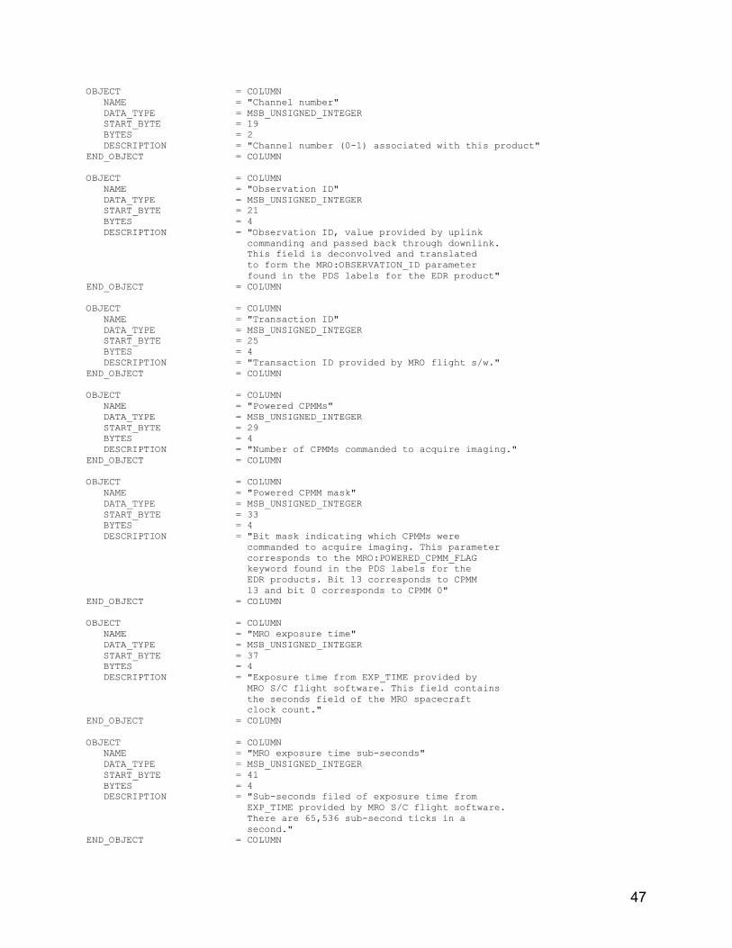
47
OBJECT = COLUMN NAME = "Channel number" DATA_TYPE = MSB_UNSIGNED_INTEGER START_BYTE = 19 BYTES = 2 DESCRIPTION = "Channel number (0-1) associated with this product" END_OBJECT = COLUMN OBJECT = COLUMN NAME = "Observation ID" DATA_TYPE = MSB_UNSIGNED_INTEGER START_BYTE = 21 BYTES = 4 DESCRIPTION = "Observation ID, value provided by uplink commanding and passed back through downlink. This field is deconvolved and translated to form the MRO:OBSERVATION_ID parameter found in the PDS labels for the EDR product" END_OBJECT = COLUMN OBJECT = COLUMN NAME = "Transaction ID" DATA_TYPE = MSB_UNSIGNED_INTEGER START_BYTE = 25 BYTES = 4 DESCRIPTION = "Transaction ID provided by MRO flight s/w." END_OBJECT = COLUMN OBJECT = COLUMN NAME = "Powered CPMMs" DATA_TYPE = MSB_UNSIGNED_INTEGER START_BYTE = 29 BYTES = 4 DESCRIPTION = "Number of CPMMs commanded to acquire imaging." END_OBJECT = COLUMN OBJECT = COLUMN NAME = "Powered CPMM mask" DATA_TYPE = MSB_UNSIGNED_INTEGER START_BYTE = 33 BYTES = 4 DESCRIPTION = "Bit mask indicating which CPMMs were commanded to acquire imaging. This parameter corresponds to the MRO:POWERED_CPMM_FLAG keyword found in the PDS labels for the EDR products. Bit 13 corresponds to CPMM 13 and bit 0 corresponds to CPMM 0" END_OBJECT = COLUMN OBJECT = COLUMN NAME = "MRO exposure time" DATA_TYPE = MSB_UNSIGNED_INTEGER START_BYTE = 37 BYTES = 4 DESCRIPTION = "Exposure time from EXP_TIME provided by MRO S/C flight software. This field contains the seconds field of the MRO spacecraft clock count." END_OBJECT = COLUMN OBJECT = COLUMN NAME = "MRO exposure time sub-seconds" DATA_TYPE = MSB_UNSIGNED_INTEGER START_BYTE = 41 BYTES = 4 DESCRIPTION = "Sub-seconds filed of exposure time from EXP_TIME provided by MRO S/C flight software. There are 65,536 sub-second ticks in a second." END_OBJECT = COLUMN

48
OBJECT = COLUMN NAME = "HiRISE exposure time" DATA_TYPE = MSB_UNSIGNED_INTEGER START_BYTE = 45 BYTES = 4 DESCRIPTION = "Exposure time as defined by the HiRISE internal clock. Except for possible drift between the instrument and spacecraft clock count, this field should be identical to the MRO exposure time field and corresponds to the seconds field of the spacecraft seconds field." END_OBJECT = COLUMN OBJECT = COLUMN NAME = "HiRISE exposure time sub-seconds" DATA_TYPE = MSB_UNSIGNED_INTEGER START_BYTE = 49 BYTES = 4 DESCRIPTION = "This field contains the conversion of the MRO sub-seconds field to the units of the HiRISE internal clock sub-seconds field. There are .10 milliseconds per tick." END_OBJECT = COLUMN OBJECT = COLUMN NAME = "Calculated analog power-on time" DATA_TYPE = MSB_UNSIGNED_INTEGER START_BYTE = 53 BYTES = 4 DESCRIPTION = "Calculated time to begin analog power on sequence in seconds." END_OBJECT = COLUMN OBJECT = COLUMN NAME = "Calculated analog power-on time sub-seconds" DATA_TYPE = MSB_UNSIGNED_INTEGER START_BYTE = 57 BYTES = 4 DESCRIPTION = "Calculated microsecond time to begin the analog power on sequence, .10 milliseconds per tick" END_OBJECT = COLUMN OBJECT = COLUMN NAME = "Analog power-on time" DATA_TYPE = MSB_UNSIGNED_INTEGER START_BYTE = 61 BYTES = 4 DESCRIPTION = "Time to begin the analog power on sequence in seconds" END_OBJECT = COLUMN OBJECT = COLUMN NAME = "Analog power-on time sub-seconds" DATA_TYPE = MSB_UNSIGNED_INTEGER START_BYTE = 65 BYTES = 4 DESCRIPTION = "Time to begin the analog power on sequence microseconds, .10 milliseconds per tick" END_OBJECT = COLUMN OBJECT = COLUMN NAME = "Expose start time" DATA_TYPE = MSB_UNSIGNED_INTEGER START_BYTE = 69 BYTES = 4 DESCRIPTION = "Actual time used to start the exposure. This parameter is used to construct the MRO:OBSERVATION_START_COUNT keyword found in the PDS labels for the EDR products." END_OBJECT = COLUMN

49
OBJECT = COLUMN NAME = "Expose start time subseconds" DATA_TYPE = MSB_UNSIGNED_INTEGER START_BYTE = 73 BYTES = 4 DESCRIPTION = "Actual time to start the exposure for the sub-seconds field. This parameter is used to construct the MRO:OBSERVATION_START_COUNT keyword found in the PDS labels for the EDR products." END_OBJECT = COLUMN OBJECT = COLUMN NAME = "Expose time delay" DATA_TYPE = MSB_UNSIGNED_INTEGER START_BYTE = 77 BYTES = 4 DESCRIPTION = "Number of system ticks to delay for the Exposure (10 msec per tick)" END_OBJECT = COLUMN OBJECT = COLUMN NAME = "Total image size" DATA_TYPE = MSB_UNSIGNED_INTEGER START_BYTE = 81 BYTES = 4 DESCRIPTION = "Number of bytes that is readout to the Solid State Recorder" END_OBJECT = COLUMN OBJECT = COLUMN NAME = "Line time commanded" DATA_TYPE = MSB_UNSIGNED_INTEGER START_BYTE = 85 BYTES = 4 DESCRIPTION = "Line time value from the EXP_LINETIME command" END_OBJECT = COLUMN OBJECT = COLUMN NAME = "Line time" DATA_TYPE = MSB_UNSIGNED_INTEGER START_BYTE = 89 BYTES = 4 DESCRIPTION = "Actual line time value used during the exposure." END_OBJECT = COLUMN OBJECT = COLUMN NAME = "Line time error" DATA_TYPE = MSB_UNSIGNED_INTEGER START_BYTE = 93 BYTES = 4 DESCRIPTION = "Flag indicating whether an error occurred with the line time parameter" END_OBJECT = COLUMN OBJECT = COLUMN NAME = "Line Time Command" DATA_TYPE = MSB_UNSIGNED_INTEGER START_BYTE = 97 BYTES = 4 DESCRIPTION = "32-bit line time command sent to the Focal Plane Electronics. This field may be used to construct value for the MRO:SCAN_EXPOSURE_DURATION keyword found in the PDS label of the EDR products" END_OBJECT = COLUMN OBJECT = COLUMN NAME = "Line Time Response" DATA_TYPE = MSB_UNSIGNED_INTEGER START_BYTE = 101 BYTES = 4 DESCRIPTION = "32-bit response from the line time command"

50
END_OBJECT = COLUMN OBJECT = COLUMN NAME = "Expose command" DATA_TYPE = MSB_UNSIGNED_INTEGER START_BYTE = 105 BYTES = 4 DESCRIPTION = "32-bit expose command sent to Focal Plane Electronics" END_OBJECT = COLUMN OBJECT = COLUMN NAME = "Expose command response" DATA_TYPE = MSB_UNSIGNED_INTEGER START_BYTE = 109 BYTES = 4 DESCRIPTION = "32-bit response from the expose command sent to the Focal Plane Electronics" END_OBJECT = COLUMN OBJECT = COLUMN NAME = "Line Time command received" DATA_TYPE = MSB_UNSIGNED_INTEGER START_BYTE = 113 BYTES = 4 DESCRIPTION = "Flag indicating the EXP_LINETIME command was received for this exposure" END_OBJECT = COLUMN OBJECT = COLUMN NAME = "Binning command received" DATA_TYPE = MSB_UNSIGNED_INTEGER START_BYTE = 116 BYTES = 4 DESCRIPTION = "Flag indicating the EXP_BINNING command was received for the exposure" END_OBJECT = COLUMN OBJECT = COLUMN NAME = "TDI command received" DATA_TYPE = MSB_UNSIGNED_INTEGER START_BYTE = 121 BYTES = 4 DESCRIPTION = "Flag indicating the EXP_TDI command was received for this exposure" END_OBJECT = COLUMN OBJECT = COLUMN NAME = "Number lines command received" DATA_TYPE = MSB_UNSIGNED_INTEGER START_BYTE = 125 BYTES = 4 DESCRIPTION = "Flag indicating the EXP_NUMLINES command was received for the exposure" END_OBJECT = COLUMN OBJECT = COLUMN NAME = "CPMM powered command received" DATA_TYPE = MSB_UNSIGNED_INTEGER START_BYTE = 129 BYTES = 4 DESCRIPTION = "Flag indicating the CPMM_PWR command was received for this exposure" END_OBJECT = COLUMN OBJECT = COLUMN NAME = "Expose time command received" DATA_TYPE = MSB_UNSIGNED_INTEGER START_BYTE = 133 BYTES = 4 DESCRIPTION = "Flag indicating the EXPOSE_TIME command was

51
received for this exposure" END_OBJECT = COLUMN OBJECT = COLUMN NAME = "LUT command received" DATA_TYPE = MSB_UNSIGNED_INTEGER START_BYTE = 137 BYTES = 4 DESCRIPTION = "Flag indicating the EXP_LUT command was received for this exposure" END_OBJECT = COLUMN OBJECT = COLUMN NAME = "Pad 2" DATA_TYPE = CHARACTER START_BYTE = 141 BYTES = 8 DESCRIPTION = "Pad bytes - unused" END_OBJECT = COLUMN OBJECT = COLUMN NAME = "Digital power commanded" DATA_TYPE = MSB_UNSIGNED_INTEGER START_BYTE = 149 BYTES = 4 DESCRIPTION = "Digital power state from the CPMM_PWR command" END_OBJECT = COLUMN OBJECT = COLUMN NAME = "Digital power value" DATA_TYPE = MSB_UNSIGNED_INTEGER START_BYTE = 153 BYTES = 4 DESCRIPTION = "Current digital power state for the CPMM, should always be 1" END_OBJECT = COLUMN OBJECT = COLUMN NAME = "Digital power error" DATA_TYPE = MSB_UNSIGNED_INTEGER START_BYTE = 157 BYTES = 4 DESCRIPTION = "If an error occurred while setting digital power" END_OBJECT = COLUMN OBJECT = COLUMN NAME = "Digital power command" DATA_TYPE = MSB_UNSIGNED_INTEGER START_BYTE = 161 BYTES = 4 DESCRIPTION = "32-bit digital power command sent to Focal Plane Electronics" END_OBJECT = COLUMN OBJECT = COLUMN NAME = "Digital power response" DATA_TYPE = MSB_UNSIGNED_INTEGER START_BYTE = 165 BYTES = 4 DESCRIPTION = "32-bit response from the Digital Power command sent to the Focal Plane Electronics" END_OBJECT = COLUMN OBJECT = COLUMN NAME = "Analog power commanded" DATA_TYPE = MSB_UNSIGNED_INTEGER START_BYTE = 169 BYTES = 4 DESCRIPTION = "Commanded parameter value - always 0 since

52
there is no analog power command" END_OBJECT = COLUMN OBJECT = COLUMN NAME = "Analog power value" DATA_TYPE = MSB_UNSIGNED_INTEGER START_BYTE = 173 BYTES = 4 DESCRIPTION = "Current analog power state for the CPMM - should always be 0" END_OBJECT = COLUMN OBJECT = COLUMN NAME = "Analog power error" DATA_TYPE = MSB_UNSIGNED_INTEGER START_BYTE = 177 BYTES = 4 DESCRIPTION = "Flag indicating error status while setting analog power" END_OBJECT = COLUMN OBJECT = COLUMN NAME = "Analog power Command" DATA_TYPE = MSB_UNSIGNED_INTEGER START_BYTE = 181 BYTES = 4 DESCRIPTION = "32-bit analog power command sent to Focal Plane Electronics" END_OBJECT = COLUMN OBJECT = COLUMN NAME = "Analog power response" DATA_TYPE = MSB_UNSIGNED_INTEGER START_BYTE = 185 BYTES = 4 DESCRIPTION = "32-bit response of analog power command from Focal Plane Electronics" END_OBJECT = COLUMN OBJECT = COLUMN NAME = "Trimming commanded" DATA_TYPE = MSB_UNSIGNED_INTEGER START_BYTE = 189 BYTES = 4 DESCRIPTION = "Line trimming value from the patchable constant trimming table" END_OBJECT = COLUMN OBJECT = COLUMN NAME = "Trimming value" DATA_TYPE = MSB_UNSIGNED_INTEGER START_BYTE = 193 BYTES = 4 DESCRIPTION = "Actual trimming value used for exposure. This field used to construct the value of the MRO:TRIM_LINES keyword found in the PDS label of the EDR products." END_OBJECT = COLUMN OBJECT = COLUMN NAME = "Trimming error" DATA_TYPE = MSB_UNSIGNED_INTEGER START_BYTE = 197 BYTES = 4 DESCRIPTION = "Trimming command error returned from Focal Plane Electronics." END_OBJECT = COLUMN OBJECT = COLUMN NAME = "Trimming command" DATA_TYPE = MSB_UNSIGNED_INTEGER

53
START_BYTE = 201 BYTES = 4 DESCRIPTION = "32-bit line trimming command sent to Focal Plane Electronics." END_OBJECT = COLUMN OBJECT = COLUMN NAME = "Trimming command response" DATA_TYPE = MSB_UNSIGNED_INTEGER START_BYTE = 205 BYTES = 4 DESCRIPTION = "32-bit trimming command response from the Focal Plane Electronics" END_OBJECT = COLUMN OBJECT = COLUMN NAME = "TDI commanded" DATA_TYPE = MSB_UNSIGNED_INTEGER START_BYTE = 209 BYTES = 4 DESCRIPTION = "TDI value from the EXP_TDI command" END_OBJECT = COLUMN OBJECT = COLUMN NAME = "TDI value" DATA_TYPE = MSB_UNSIGNED_INTEGER START_BYTE = 213 BYTES = 4 DESCRIPTION = "Actual TDI value used for exposure. This field may be used to construct the value of the MRO:TDI keyword found in the PDS label of the EDR products." END_OBJECT = COLUMN OBJECT = COLUMN NAME = "TDI error" DATA_TYPE = MSB_UNSIGNED_INTEGER START_BYTE = 217 BYTES = 4 DESCRIPTION = "Error value if an error occurred" END_OBJECT = COLUMN OBJECT = COLUMN NAME = "TDI command" DATA_TYPE = MSB_UNSIGNED_INTEGER START_BYTE = 221 BYTES = 4 DESCRIPTION = "32-bit TDI command sent to the Focal Plane Electronics" END_OBJECT = COLUMN OBJECT = COLUMN NAME = "TDI response" DATA_TYPE = MSB_UNSIGNED_INTEGER START_BYTE = 225 BYTES = 4 DESCRIPTION = "32-bit response to the TDI command from Focal Plane Electronics" END_OBJECT = COLUMN OBJECT = COLUMN NAME = "Number lines commanded" DATA_TYPE = MSB_UNSIGNED_INTEGER START_BYTE = 229 BYTES = 4 DESCRIPTION = "Number of post-binned lines value from EXP_NUMLINES command" END_OBJECT = COLUMN OBJECT = COLUMN NAME = "Number of lines value"

54
DATA_TYPE = MSB_UNSIGNED_INTEGER START_BYTE = 233 BYTES = 4 DESCRIPTION = "Actual value number of post-binned lines used for exposure. This field may be used to construct the value of the LINES keyword found in the IMAGE object of the PDS label of the EDR products." END_OBJECT = COLUMN OBJECT = COLUMN NAME = "Number of lines error" DATA_TYPE = MSB_UNSIGNED_INTEGER START_BYTE = 237 BYTES = 4 DESCRIPTION = "Error code if an error occurred" END_OBJECT = COLUMN OBJECT = COLUMN NAME = "Number of lines commanded" DATA_TYPE = MSB_UNSIGNED_INTEGER START_BYTE = 241 BYTES = 4 DESCRIPTION = "32-bit number of lines command sent to the Focal Plane Electronics" END_OBJECT = COLUMN OBJECT = COLUMN NAME = "Number of lines response" DATA_TYPE = MSB_UNSIGNED_INTEGER START_BYTE = 245 BYTES = 4 DESCRIPTION = "32-bit response of the number of lines command from the Focal Planet Electronics" END_OBJECT = COLUMN OBJECT = COLUMN NAME = "Binning commanded" DATA_TYPE = MSB_UNSIGNED_INTEGER START_BYTE = 249 BYTES = 4 DESCRIPTION = "Binning value from the EXP_BINNING command" END_OBJECT = COLUMN OBJECT = COLUMN NAME = "Binning value" DATA_TYPE = MSB_UNSIGNED_INTEGER START_BYTE = 253 BYTES = 4 DESCRIPTION = "Actual binning valued used for the exposure. This field may be used to construct the value of the MRO:BINNING keyword found in the PDS label of the EDR products." END_OBJECT = COLUMN OBJECT = COLUMN NAME = "Binning error" DATA_TYPE = MSB_UNSIGNED_INTEGER START_BYTE = 257 BYTES = 4 DESCRIPTION = "Error value if an error occurred" END_OBJECT = COLUMN OBJECT = COLUMN NAME = "Binning command" DATA_TYPE = MSB_UNSIGNED_INTEGER START_BYTE = 261 BYTES = 4 DESCRIPTION = "32-bit binning command sent to the Focal Planet Electronics" END_OBJECT = COLUMN

55
OBJECT = COLUMN NAME = "Binning response" DATA_TYPE = MSB_UNSIGNED_INTEGER START_BYTE = 265 BYTES = 4 DESCRIPTION = "32-bit response to binning command from Focal Plane Electronics" END_OBJECT = COLUMN OBJECT = COLUMN NAME = "LUT type commanded" DATA_TYPE = MSB_UNSIGNED_INTEGER START_BYTE = 269 BYTES = 4 DESCRIPTION = "Lookup Table type value from the EXP_LUT command." END_OBJECT = COLUMN OBJECT = COLUMN NAME = "LUT type value" DATA_TYPE = MSB_UNSIGNED_INTEGER START_BYTE = 273 BYTES = 4 DESCRIPTION = "Actual LUT type value used for exposure. This field is used to construct the MRO:LOOKUP_TABLE_TYPE keyword value found in the PDS labels of the EDR products." END_OBJECT = COLUMN OBJECT = COLUMN NAME = "LUT type error" DATA_TYPE = MSB_UNSIGNED_INTEGER START_BYTE = 277 BYTES = 4 DESCRIPTION = "If an error occurred in the LUT type command" END_OBJECT = COLUMN OBJECT = COLUMN NAME = "LUT minimum value commanded" DATA_TYPE = MSB_UNSIGNED_INTEGER START_BYTE = 281 BYTES = 4 DESCRIPTION = "LUT minimum value from the EXP_LUT command" END_OBJECT = COLUMN OBJECT = COLUMN NAME = "LUT minimum value" DATA_TYPE = MSB_UNSIGNED_INTEGER START_BYTE = 285 BYTES = 4 DESCRIPTION = "Actual LUT minimum value used for exposure. This field is used to construct the MRO:LOOKUP_TABLE_MINIMUM keyword value found in the PDS labels of the EDR products." END_OBJECT = COLUMN OBJECT = COLUMN NAME = "LUT minimum value error" DATA_TYPE = MSB_UNSIGNED_INTEGER START_BYTE = 289 BYTES = 4 DESCRIPTION = "If an error occurred in the LUT minimum value" END_OBJECT = COLUMN OBJECT = COLUMN NAME = "LUT maximum value commanded" DATA_TYPE = MSB_UNSIGNED_INTEGER START_BYTE = 293 BYTES = 4 DESCRIPTION = "LUT maximum value from the EXP_LUT command" END_OBJECT = COLUMN

56
OBJECT = COLUMN NAME = "LUT maximum value" DATA_TYPE = MSB_UNSIGNED_INTEGER START_BYTE = 297 BYTES = 4 DESCRIPTION = "Actual LUT maximum value used for exposure. This field is used to construct the MRO:LOOKUP_TABLE_MAXIMUM keyword value found in the PDS labels of the EDR products." END_OBJECT = COLUMN OBJECT = COLUMN NAME = "LUT maximum value error" DATA_TYPE = MSB_UNSIGNED_INTEGER START_BYTE = 301 BYTES = 4 DESCRIPTION = "If an error occurred in the LUT maximum value" END_OBJECT = COLUMN OBJECT = COLUMN NAME = "LUT median value commanded" DATA_TYPE = MSB_UNSIGNED_INTEGER START_BYTE = 305 BYTES = 4 DESCRIPTION = "LUT median value from the EXP_LUT command" END_OBJECT = COLUMN OBJECT = COLUMN NAME = "LUT median value" DATA_TYPE = MSB_UNSIGNED_INTEGER START_BYTE = 309 BYTES = 1 DESCRIPTION = "Actual LUT median value used for exposure. This field is used to construct the MRO:LOOKUP_TABLE_MEDIAN keyword value found in the PDS labels of the EDR products." END_OBJECT = COLUMN OBJECT = COLUMN NAME = "LUT median value error" DATA_TYPE = MSB_UNSIGNED_INTEGER START_BYTE = 313 BYTES = 4 DESCRIPTION = "If an error occurred in the LUT median value" END_OBJECT = COLUMN OBJECT = COLUMN NAME = "LUT K value commanded" DATA_TYPE = MSB_UNSIGNED_INTEGER START_BYTE = 317 BYTES = 4 DESCRIPTION = "LUT k value from the EXP_LUT command" END_OBJECT = COLUMN OBJECT = COLUMN NAME = "LUT K value" DATA_TYPE = MSB_UNSIGNED_INTEGER START_BYTE = 321 BYTES = 4 DESCRIPTION = "Actual LUT K value used for exposure. This field is used to construct the MRO:LOOKUP_TABLE_K_VALUE keyword value found in the PDS labels of the EDR products." END_OBJECT = COLUMN OBJECT = COLUMN NAME = "LUT K value error" DATA_TYPE = MSB_UNSIGNED_INTEGER START_BYTE = 325 BYTES = 4 DESCRIPTION = "If an error occurred in the LUT K value"

57
END_OBJECT = COLUMN OBJECT = COLUMN NAME = "LUT stored value commanded" DATA_TYPE = MSB_UNSIGNED_INTEGER START_BYTE = 329 BYTES = 4 DESCRIPTION = "LUT stored valued from the EXP_LUT command" END_OBJECT = COLUMN OBJECT = COLUMN NAME = "LUT stored value" DATA_TYPE = MSB_UNSIGNED_INTEGER START_BYTE = 333 BYTES = 4 DESCRIPTION = "Actual value used for exposure. This field is used to construct the MRO:LOOKUP_TABLE_TABLE_NUMBER keyword value found in the PDS labels of the EDR products." END_OBJECT = COLUMN OBJECT = COLUMN NAME = "LUT stored value error" DATA_TYPE = MSB_UNSIGNED_INTEGER START_BYTE = 337 BYTES = 4 DESCRIPTION = "Actual LUT stored value used" END_OBJECT = COLUMN OBJECT = COLUMN NAME = "LUT stored value command" DATA_TYPE = MSB_UNSIGNED_INTEGER START_BYTE = 341 BYTES = 4 DESCRIPTION = "32-bit command sent to the Focal Plane Electronics - valid only in the case of a NULL LUT" END_OBJECT = COLUMN OBJECT = COLUMN NAME = "LUT response" DATA_TYPE = MSB_UNSIGNED_INTEGER START_BYTE = 345 BYTES = 4 DESCRIPTION = "32-bit LUT command response from the Focal Plane Electronics - valid only in the case of a NULL LUT" END_OBJECT = COLUMN OBJECT = COLUMN NAME = "Exposure time" DATA_TYPE = MSB_UNSIGNED_INTEGER START_BYTE = 349 BYTES = 4 DESCRIPTION = "The flight s/w calculated time in milliseconds the CPMM will expose. This field may be used to calculate the value of the MRO:SCAN_EXPOSURE_DURATION keyword in the PDS label of the EDR products." END_OBJECT = COLUMN OBJECT = COLUMN NAME = "Channel 0 readout start time seconds" DATA_TYPE = MSB_UNSIGNED_INTEGER START_BYTE = 353 BYTES = 4 DESCRIPTION = "The seconds time of the start of readout for CPMM channel 0" END_OBJECT = COLUMN OBJECT = COLUMN

58
NAME = "Channel 0 readout start time microseconds" DATA_TYPE = MSB_UNSIGNED_INTEGER START_BYTE = 357 BYTES = 4 DESCRIPTION = "The microseconds time of the start of readout for CPMM channel 0" END_OBJECT = COLUMN OBJECT = COLUMN NAME = "Channel 1 readout start time seconds" DATA_TYPE = MSB_UNSIGNED_INTEGER START_BYTE = 361 BYTES = 4 DESCRIPTION = "The seconds time of the start of readout for CPMM channel 1" END_OBJECT = COLUMN OBJECT = COLUMN NAME = "Channel 1 readout start time microseconds" DATA_TYPE = MSB_UNSIGNED_INTEGER START_BYTE = 365 BYTES = 4 DESCRIPTION = "The microseconds time of the start of readout for CPMM channel 1" END_OBJECT = COLUMN OBJECT = COLUMN NAME = "Byte pad value" DATA_TYPE = MSB_UNSIGNED_INTEGER START_BYTE = 369 BYTES = 4 DESCRIPTION = "The number of bytes the CPMM will pad its readout" END_OBJECT = COLUMN OBJECT = COLUMN NAME = "Pixels per line" DATA_TYPE = MSB_UNSIGNED_INTEGER START_BYTE = 373 BYTES = 4 DESCRIPTION = "Total number of pixel per line." END_OBJECT = COLUMN OBJECT = COLUMN NAME = "Extra pixel 3x3 binning" DATA_TYPE = MSB_UNSIGNED_INTEGER START_BYTE = 377 BYTES = 4 DESCRIPTION = "The value to add to the number of pixels per line to account for a binning value of 3" END_OBJECT = COLUMN OBJECT = COLUMN NAME = "Pixel size" DATA_TYPE = MSB_UNSIGNED_INTEGER START_BYTE = 381 BYTES = 4 DESCRIPTION = "The number of bytes per pixel. This field used to construct the SAMPLE_TYPE keyword found in the PDS labels of the EDR products." END_OBJECT = COLUMN OBJECT = COLUMN NAME = "pixel data size" DATA_TYPE = MSB_UNSIGNED_INTEGER START_BYTE = 385 BYTES = 4 DESCRIPTION = "The pixel data size per CPMM channel. Does not include LUT table, Engineering data or Line IDs" END_OBJECT = COLUMN

59
OBJECT = COLUMN NAME = "Line header size" DATA_TYPE = MSB_UNSIGNED_INTEGER START_BYTE = 389 BYTES = 4 DESCRIPTION = "The line header size computed by the Focal Plane Electronics" END_OBJECT = COLUMN OBJECT = COLUMN NAME = "CPMM channel readout size" DATA_TYPE = MSB_UNSIGNED_INTEGER START_BYTE = 393 BYTES = 4 DESCRIPTION = "Number of bytes the CPMM channel will read out. includes pixel data, LUT, Engineering data and byte pad" END_OBJECT = COLUMN OBJECT = COLUMN NAME = "CPMM readout time in flight software ticks" DATA_TYPE = MSB_UNSIGNED_INTEGER START_BYTE = 397 BYTES = 3 DESCRIPTION = "Calculated CPMM channel readout time in flight software ticks (10 ms per tick)" END_OBJECT = COLUMN OBJECT = COLUMN NAME = "Maximum storable lines" DATA_TYPE = MSB_UNSIGNED_INTEGER START_BYTE = 401 BYTES = 4 DESCRIPTION = "The maximum number of lines, given the LUT and binning parameters that can be stored in the CPMM SRAM" END_OBJECT = COLUMN OBJECT = COLUMN NAME = "Maximum storable lines exceeded" DATA_TYPE = MSB_UNSIGNED_INTEGER START_BYTE = 405 BYTES = 4 DESCRIPTION = "Over subscribed the CPMM SRAM data" END_OBJECT = COLUMN OBJECT = COLUMN NAME = "Actual lines to collect" DATA_TYPE = MSB_UNSIGNED_INTEGER START_BYTE = 409 BYTES = 4 DESCRIPTION = "The total lines that will actually be collected and stored in the CPMM SRAM. This will only differ from the number of lines in the case where the CPMM is oversubscribed." END_OBJECT = COLUMN OBJECT = COLUMN NAME = "Total lines to expose" DATA_TYPE = MSB_UNSIGNED_INTEGER START_BYTE = 413 BYTES = 4 DESCRIPTION = "Total lines the CPMM will expose and is dependent on the trimming and binning parameters" END_OBJECT = COLUMN OBJECT = COLUMN NAME = "Line Time" DATA_TYPE = MSB_UNSIGNED_INTEGER

60
START_BYTE = 417 BYTES = 4 DESCRIPTION = "The time in nanoseconds per line during the exposure." END_OBJECT = COLUMN OBJECT = COLUMN NAME = "Channel 0 readout command" DATA_TYPE = MSB_UNSIGNED_INTEGER START_BYTE = 421 BYTES = 4 DESCRIPTION = "The readout command sent to the Focal Plane Electronics for CPMM channel 0, will be 0 for the CPMM channel 1 science channel header" END_OBJECT = COLUMN OBJECT = COLUMN NAME = "Channel 1 readout command" DATA_TYPE = MSB_UNSIGNED_INTEGER START_BYTE = 425 BYTES = 4 DESCRIPTION = "The readout command sent to the Focal Plane Electronics for CPMM channel 1, will be 0 for the CPMM Channel 0 science channel header" END_OBJECT = COLUMN OBJECT = COLUMN NAME = "Channel 0 readout command response" DATA_TYPE = MSB_UNSIGNED_INTEGER START_BYTE = 429 BYTES = 4 DESCRIPTION = "The readout response from the Focal Plane Electronics for CPMM channel 0, will be 0 for CPMM channel 1 science channel header" END_OBJECT = COLUMN OBJECT = COLUMN NAME = "Channel 1 readout command response" DATA_TYPE = MSB_UNSIGNED_INTEGER START_BYTE = 433 BYTES = 4 DESCRIPTION = "The readout response from the Focal Plane Electronics for CPMM channel 1, will be 0 for CPMM channel 0 science channel header" END_OBJECT = COLUMN OBJECT = COLUMN NAME = "Pad 3" DATA_TYPE = CHARACTER START_BYTE = 437 BYTES = 12 DESCRIPTION = "Pad bytes - unused" END_OBJECT = COLUMN OBJECT = COLUMN NAME = "Optical bench flexure temperature count" DATA_TYPE = MSB_UNSIGNED_INTEGER START_BYTE = 449 BYTES = 2 DESCRIPTION = "Raw count of the ADC temperature sensor - optical bench near +X MOR flexure location. This field is used to construct the MRO:OPT_BNCH_FLEXURE_TEMPERATURE keyword found in the EDR products." END_OBJECT = COLUMN OBJECT = COLUMN

61
NAME = "Optical bench territory mirror temperature count" DATA_TYPE = MSB_UNSIGNED_INTEGER START_BYTE = 451 BYTES = 2 DESCRIPTION = "Raw count of the ADC temperature sensor - optical bench near the tertiary mirror location. This filed used to construct the MRO:OPT_BNCH_MIRROR_TEMPERATURE keyword found in the EDR products." END_OBJECT = COLUMN OBJECT = COLUMN NAME = "Optical bench fold flat temperate count" DATA_TYPE = MSB_UNSIGNED_INTEGER START_BYTE = 453 BYTES = 2 DESCRIPTION = "Raw count of the ADC temperature sensor - optical bench fold flat location. This filed used to construct the MRO:OPT_BNCH_FOLD_FLAT_TEMPERATURE keyword found in the EDR products." END_OBJECT = COLUMN OBJECT = COLUMN NAME = "Optical bench FPA temperature count" DATA_TYPE = MSB_UNSIGNED_INTEGER START_BYTE = 455 BYTES = 2 DESCRIPTION = "Raw temperature count of the ADC sensor - optical bench near FPA location. This filed used to construct the MRO:OPT_BNCH_FPA_TEMPERATURE keyword found in the EDR products." END_OBJECT = COLUMN OBJECT = COLUMN NAME = "Optical bench Focal Plane Electronics temperature count" DATA_TYPE = MSB_UNSIGNED_INTEGER START_BYTE = 457 BYTES = 2 DESCRIPTION = "Raw count of the ADC sensor - optical bench near Focal Plane Electronics location. This filed used to construct the MRO:OPT_BNCH_FPE_TEMPERATURE keyword found in the EDR products." END_OBJECT = COLUMN OBJECT = COLUMN NAME = "Optical bench living room temperature count" DATA_TYPE = MSB_UNSIGNED_INTEGER START_BYTE = 459 BYTES = 2 DESCRIPTION = "Raw count of the ADC temperature sensor - optical bench in sunken living room location. This filed used to construct the MRO:OPT_BNCH_LIVING_RM_TEMPERATURE keyword found in the EDR products." END_OBJECT = COLUMN OBJECT = COLUMN NAME = "Optical bench box beam temperature count" DATA_TYPE = MSB_UNSIGNED_INTEGER START_BYTE = 461 BYTES = 2 DESCRIPTION = "Raw count of the ADC temperature sensor - optical bench near box beam (+Y face) location. This filed used to construct the MRO:OPT_BNCH_BOX_BEAM_TEMPERATURE keyword found in the EDR products." END_OBJECT = COLUMN

62
OBJECT = COLUMN NAME = "Optical bench cover temperature count" DATA_TYPE = MSB_UNSIGNED_INTEGER START_BYTE = 463 BYTES = 2 DESCRIPTION = "Raw count of the ADC temperature sensor - optical bench cover (external) location. This filed used to construct the MRO:OPT_BNCH_COVER_TEMPERATURE keyword found in the EDR products." END_OBJECT = COLUMN OBJECT = COLUMN NAME = "Field Stop temperature count" DATA_TYPE = MSB_UNSIGNED_INTEGER START_BYTE = 465 BYTES = 2 DESCRIPTION = "Raw count of the ADC temperature sensor - field stop location. This filed used to construct the MRO:FIELD_STOP_TEMPERATURE keyword found in the EDR products." END_OBJECT = COLUMN OBJECT = COLUMN NAME = "FPA +Y side temperature count" DATA_TYPE = MSB_UNSIGNED_INTEGER START_BYTE = 467 BYTES = 2 DESCRIPTION = "Raw count of the ADC temperature sensor - FPA +Y side location. This filed used to construct the MRO:FPA_POSITIVE_Y_TEMPERATURE keyword found in the EDR products." END_OBJECT = COLUMN OBJECT = COLUMN NAME = "FPA -Y side temperature count" DATA_TYPE = MSB_UNSIGNED_INTEGER START_BYTE = 469 BYTES = 2 DESCRIPTION = "Raw count of the ADC temperature sensor - FPA -y side location. This filed used to construct the MRO:FPA_NEGATIVE_Y_TEMPERATURE keyword found in the EDR products." END_OBJECT = COLUMN OBJECT = COLUMN NAME = "FPE temperature count" DATA_TYPE = MSB_UNSIGNED_INTEGER START_BYTE = 471 BYTES = 2 DESCRIPTION = "Raw count of the ADC temperature sensor - Focal Plane Electronics location. This filed used to construct the MRO:FPE_TEMPERATURE keyword found in the EDR products." END_OBJECT = COLUMN OBJECT = COLUMN NAME = "Primary mirror +Y temperature count" DATA_TYPE = MSB_UNSIGNED_INTEGER START_BYTE = 473 BYTES = 2 DESCRIPTION = "Raw count of the ADC temperature sensor - primary mirror +Y location. This filed used to construct the MRO:PRIMARY_MIRROR_MNT_TEMPERAUTRE keyword found in the EDR products."

63
END_OBJECT = COLUMN OBJECT = COLUMN NAME = "Primary mirror at maximum thickness temperature count" DATA_TYPE = MSB_UNSIGNED_INTEGER START_BYTE = 475 BYTES = 2 DESCRIPTION = "Raw count of the ADC temperature sensor - primary mirror at maximum thickness location. This filed used to construct the MRO:PRIMARY_MIRROR_TEMPERATURE keyword found in the EDR products." END_OBJECT = COLUMN OBJECT = COLUMN NAME = "Primary mirror baffle temperature count" DATA_TYPE = MSB_UNSIGNED_INTEGER START_BYTE = 477 BYTES = 2 DESCRIPTION = "Raw count of the ADC temperature sensor - primary mirror baffle near base (external) location. This filed used to construct the MRO:PRIMARY_MIRROR_BAF_TEMPERATURE keyword found in the EDR products." END_OBJECT = COLUMN OBJECT = COLUMN NAME = "Metering Structure leg 0-A temperature count" DATA_TYPE = MSB_UNSIGNED_INTEGER START_BYTE = 479 BYTES = 2 DESCRIPTION = "Raw count of the ADC temperature sensor - metering structure truss leg 0-A leg location. This filed used to construct the MRO:MS_TRUSS_LEG_0_A_TEMPERATURE keyword found in the EDR products." END_OBJECT = COLUMN OBJECT = COLUMN NAME = "Metering Structure leg 0-B temperature count" DATA_TYPE = MSB_UNSIGNED_INTEGER START_BYTE = 481 BYTES = 2 DESCRIPTION = "Raw count of the ADC temperature sensor - metering structure truss leg 0-B leg location. This filed used to construct the MRO:MS_TRUSS_LEG_0_B_TEMPERATURE keyword found in the EDR products." END_OBJECT = COLUMN OBJECT = COLUMN NAME = "Metering Structure leg 120-A temperature count" DATA_TYPE = MSB_UNSIGNED_INTEGER START_BYTE = 483 BYTES = 2 DESCRIPTION = "Raw count of the ADC temperature sensor - metering structure truss leg 120-A leg location. This filed used to construct the MRO:MS_TRUSS_LEG_120_A_TEMPERATURE keyword found in the EDR products." END_OBJECT = COLUMN OBJECT = COLUMN NAME = "Metering Structure leg 120-B temperature count" DATA_TYPE = MSB_UNSIGNED_INTEGER START_BYTE = 485 BYTES = 2 DESCRIPTION = "Raw count of the ADC temperature sensor - metering structure truss leg 120-B leg location. This filed used to construct the

64
MRO:MS_TRUSS_LEG_120_B_TEMPERATURE keyword found in the EDR products." END_OBJECT = COLUMN OBJECT = COLUMN NAME = "Metering Structure leg 240-A temperature count" DATA_TYPE = MSB_UNSIGNED_INTEGER START_BYTE = 487 BYTES = 2 DESCRIPTION = "Raw count of the ADC temperature sensor - metering structure truss leg 240-A leg location. This filed used to construct the MRO:MS_TRUSS_LEG_240_A_TEMPERATURE keyword found in the EDR products." END_OBJECT = COLUMN OBJECT = COLUMN NAME = "Metering Structure leg 240-B temperature count" DATA_TYPE = MSB_UNSIGNED_INTEGER START_BYTE = 489 BYTES = 2 DESCRIPTION = "Raw count of the ADC temperature sensor - metering structure truss leg 240-B leg location. This filed used to construct the MRO:MS_TRUSS_LEG_249_B_TEMPERATURE keyword found in the EDR products." END_OBJECT = COLUMN OBJECT = COLUMN NAME = "Barrel Baffle temperature count" DATA_TYPE = MSB_UNSIGNED_INTEGER START_BYTE = 491 BYTES = 2 DESCRIPTION = "Raw count of the ADC temperature sensor - barrel baffle location. This filed used to construct the MRO:BARREL_BAFFLE_TEMPERATURE keyword found in the EDR products." END_OBJECT = COLUMN OBJECT = COLUMN NAME = "Sun shade under MLI temperature count" DATA_TYPE = MSB_UNSIGNED_INTEGER START_BYTE = 493 BYTES = 2 DESCRIPTION = "Raw count of the ADC temperature sensor - sunshade under MLI location. This filed used to construct the MRO:SUN_SHADE_TEMPERATURE keyword found in the EDR products." END_OBJECT = COLUMN OBJECT = COLUMN NAME = "Spider leg at 30 temperature count" DATA_TYPE = MSB_UNSIGNED_INTEGER START_BYTE = 495 BYTES = 2 DESCRIPTION = "Raw count of the ADC temperature sensor - spider leg at 30 location. This filed used to construct the MRO:SPIDER_LEG_30_TEMPERATURE keyword found in the EDR products." END_OBJECT = COLUMN OBJECT = COLUMN NAME = "Spider leg at 150 temperature count" DATA_TYPE = MSB_UNSIGNED_INTEGER START_BYTE = 497 BYTES = 2 DESCRIPTION = "Raw count of the ADC temperature sensor - spider leg at 150 location.

65
This filed used to construct the MRO:SPIDER_LEG_150_TEMPERATURE keyword found in the EDR products." END_OBJECT = COLUMN OBJECT = COLUMN NAME = "Spider leg at 270 temperature count" DATA_TYPE = MSB_UNSIGNED_INTEGER START_BYTE = 499 BYTES = 2 DESCRIPTION = "Raw count of the ADC temperature sensor - spider leg at 270 location. This filed used to construct the MRO:SPIDER_LEG_270_TEMPERATURE keyword found in the EDR products." END_OBJECT = COLUMN OBJECT = COLUMN NAME = "Secondary mirror metering ring temperature count" DATA_TYPE = MSB_UNSIGNED_INTEGER START_BYTE = 501 BYTES = 2 DESCRIPTION = "Raw count of the ADC temperature sensor - secondary mirror metering ring location. This filed used to construct the MRO:SEC_MIRROR_MTR_RNG_TEMPERATURE keyword found in the EDR products." END_OBJECT = COLUMN OBJECT = COLUMN NAME = "Secondary mirror temperature count" DATA_TYPE = MSB_UNSIGNED_INTEGER START_BYTE = 503 BYTES = 2 DESCRIPTION = "Raw count of the ADC temperature sensor - secondary mirror location. This filed used to construct the MRO:SEC_MIRROR_TEMPERATURE keyword found in the EDR products." END_OBJECT = COLUMN OBJECT = COLUMN NAME = "Secondary mirror baffle temperature count" DATA_TYPE = MSB_UNSIGNED_INTEGER START_BYTE = 505 BYTES = 2 DESCRIPTION = "Raw count of the ADC temperature sensor - secondary mirror baffle near base (external) location. This filed used to construct the MRO:SEC_MIRROR_BAFFLE_TEMPERATURE keyword found in the EDR products." END_OBJECT = COLUMN OBJECT = COLUMN NAME = "IEA temperature count" DATA_TYPE = MSB_UNSIGNED_INTEGER START_BYTE = 507 BYTES = 2 DESCRIPTION = "Raw count of the ADC temperature sensor - IEA location. This filed used to construct the MRO:IEA_TEMPERATURE keyword found in the EDR products." END_OBJECT = COLUMN OBJECT = COLUMN NAME = "Focus motor temperature count" DATA_TYPE = MSB_UNSIGNED_INTEGER START_BYTE = 509

66
BYTES = 2 DESCRIPTION = "Raw count of the ADC temperature sensor - focus mirror location. This filed used to construct the MRO:FOCUS_MOTOR_TEMPERATURE keyword found in the EDR products." END_OBJECT = COLUMN OBJECT = COLUMN NAME = "CPMM +29 voltage count" DATA_TYPE = MSB_UNSIGNED_INTEGER START_BYTE = 511 BYTES = 2 DESCRIPTION = "Raw count of the CPMM voltage. This filed used to construct the MRO:CPMM_POSITIVE_29_VOLTAGE keyword found in the EDR products." END_OBJECT = COLUMN OBJECT = COLUMN NAME = "CPMM +29 current count" DATA_TYPE = MSB_UNSIGNED_INTEGER START_BYTE = 513 BYTES = 2 DESCRIPTION = "Raw count of the CPMM +29 current. This filed used to construct the MRO:CPMM_POSITIVE_29_CURRENT keyword found in the EDR products." END_OBJECT = COLUMN OBJECT = COLUMN NAME = "CPMM +10 voltage count" DATA_TYPE = MSB_UNSIGNED_INTEGER START_BYTE = 515 BYTES = 2 DESCRIPTION = "Raw count of the CPMM +10 voltage. This filed used to construct the MRO:CPMM_POSITIVE_10_VOLTAGE keyword found in the EDR products." END_OBJECT = COLUMN OBJECT = COLUMN NAME = "CPMM +10 current count" DATA_TYPE = MSB_UNSIGNED_INTEGER START_BYTE = 517 BYTES = 2 DESCRIPTION = "Raw count of the CPMM +10 current. This filed used to construct the MRO:CPMM_POSITIVE_10_CURRENT keyword found in the EDR products." END_OBJECT = COLUMN OBJECT = COLUMN NAME = "CPMM +5 voltage count" DATA_TYPE = MSB_UNSIGNED_INTEGER START_BYTE = 519 BYTES = 2 DESCRIPTION = "Raw count of the CPMM +5 voltage. This filed used to construct the MRO:CPMM_POSITIVE_5_VOLTAGE keyword found in the EDR products." END_OBJECT = COLUMN OBJECT = COLUMN NAME = "CPMM +5 current count"

67
DATA_TYPE = MSB_UNSIGNED_INTEGER START_BYTE = 521 BYTES = 2 DESCRIPTION = "Raw count of the CPMM +5 current. This filed used to construct the MRO:CPMM_POSITIVE_5_CURRENT keyword found in the EDR products." END_OBJECT = COLUMN OBJECT = COLUMN NAME = "CPMM +3.3 voltage count" DATA_TYPE = MSB_UNSIGNED_INTEGER START_BYTE = 523 BYTES = 2 DESCRIPTION = "Raw count of the CPMM +3.3. voltage. This filed used to construct the MRO:CPMM_POSITIVE_3_3_VOLTAGE keyword found in the EDR products." END_OBJECT = COLUMN OBJECT = COLUMN NAME = "CPMM +3.3 current count" DATA_TYPE = MSB_UNSIGNED_INTEGER START_BYTE = 525 BYTES = 2 DESCRIPTION = "Raw count of the CPMM +3.3 current. This filed used to construct the MRO:CPMM_POSITIVE_3_3_CURRENT keyword found in the EDR products." END_OBJECT = COLUMN OBJECT = COLUMN NAME = "CPMM +2.5 voltage count" DATA_TYPE = MSB_UNSIGNED_INTEGER START_BYTE = 527 BYTES = 2 DESCRIPTION = "Raw count of the CPMM +2.5 voltage. This filed used to construct the MRO:CPMM_POSITIVE_2_5_VOLTAGE keyword found in the EDR products." END_OBJECT = COLUMN OBJECT = COLUMN NAME = "CPMM +2.5 current count" DATA_TYPE = MSB_UNSIGNED_INTEGER START_BYTE = 529 BYTES = 2 DESCRIPTION = "Raw count of the CPMM +2.5 current. This filed used to construct the MRO:CPMM_POSITIVE_2_5_CURRENT keyword found in the EDR products." END_OBJECT = COLUMN OBJECT = COLUMN NAME = "CPMM +1.8 voltage count" DATA_TYPE = MSB_UNSIGNED_INTEGER START_BYTE = 531 BYTES = 2 DESCRIPTION = "Raw count of the CPMM +1.8 voltage. This filed used to construct the MRO:CPMM_POSITIVE_1_8_VOLTAGE keyword found in the EDR products." END_OBJECT = COLUMN OBJECT = COLUMN

68
NAME = "CPMM +1.8 current count" DATA_TYPE = MSB_UNSIGNED_INTEGER START_BYTE = 533 BYTES = 2 DESCRIPTION = "Raw count of the CPMM +1.8 current. This filed used to construct the MRO:CPMM_POSITIVE_1_8_CURRENT keyword found in the EDR products." END_OBJECT = COLUMN OBJECT = COLUMN NAME = "CPMM -5 voltage count" DATA_TYPE = MSB_UNSIGNED_INTEGER START_BYTE = 535 BYTES = 2 DESCRIPTION = "Raw count of the CPMM -5 voltage. This filed used to construct the MRO:CPMM_NEGATIVE_5_VOLTAGE keyword found in the EDR products." END_OBJECT = COLUMN OBJECT = COLUMN NAME = "CPMM -5 current count" DATA_TYPE = MSB_UNSIGNED_INTEGER START_BYTE = 537 BYTES = 2 DESCRIPTION = "Raw count of the CPMM -5 current. This filed used to construct the MRO:CPMM_NEGATIVE_5_CURRENT keyword found in the EDR products." END_OBJECT = COLUMN OBJECT = COLUMN NAME = "IE PWS board temperature count" DATA_TYPE = MSB_UNSIGNED_INTEGER START_BYTE = 539 BYTES = 2 DESCRIPTION = "Raw count of the ADC temperature sensor - IE PWS Board location. This filed used to construct the MRO:IE_PWS_BOARD_TEMPERATURE keyword found in the EDR products." END_OBJECT = COLUMN OBJECT = COLUMN NAME = "CPMM PWS Board temperature count" DATA_TYPE = MSB_UNSIGNED_INTEGER START_BYTE = 541 BYTES = 2 DESCRIPTION = "Raw count of the ADC temperature sensor - CPMM PWS board location. This filed used to construct the MRO:CPMM_PWS_BOARD_TEMPERATURE keyword found in the EDR products." END_OBJECT = COLUMN OBJECT = COLUMN NAME = "Total Heater Current count" DATA_TYPE = MSB_UNSIGNED_INTEGER START_BYTE = 543 BYTES = 2 DESCRIPTION = "Raw count of the total heater current. This filed used to construct the MRO:HEATER_CURRENT keyword found in the EDR products." END_OBJECT = COLUMN

69
OBJECT = COLUMN NAME = "Mech/TLM board temperature count" DATA_TYPE = MSB_UNSIGNED_INTEGER START_BYTE = 545 BYTES = 2 DESCRIPTION = "Raw count of the ADC temperature sensor - Mech/TLM board location. This filed used to construct the MRO:MECH_TLM_BOARD_TEMPERATURE keyword found in the EDR products." END_OBJECT = COLUMN OBJECT = COLUMN NAME = "Instrument control board temperature count" DATA_TYPE = MSB_UNSIGNED_INTEGER START_BYTE = 547 BYTES = 2 DESCRIPTION = "Raw count of the ADC temperature sensor - instrument control board location. This filed used to construct the MRO:INST_CONT_BOARD_TEMPERATURE keyword found in the EDR products." END_OBJECT = COLUMN OBJECT = COLUMN NAME = "Instrument control FPGA 2.5 voltage count" DATA_TYPE = MSB_UNSIGNED_INTEGER START_BYTE = 549 BYTES = 2 DESCRIPTION = "Raw count of the instrument control 2.5 voltage monitor. This filed used to construct the MRO:INST_CONT_FPGA_POS_2_5_VOLTAGE keyword found in the EDR products." END_OBJECT = COLUMN OBJECT = COLUMN NAME = "Mech/TLM FPGA 2.5 voltage count" DATA_TYPE = MSB_UNSIGNED_INTEGER START_BYTE = 551 BYTES = 2 DESCRIPTION = "Raw count of the Mech/TLM FPGA 2.5 voltage monitor. This filed used to construct the MRO:MECH_TLM_FPGA_POS_2_5_VOLTAGE keyword found in the EDR products." END_OBJECT = COLUMN OBJECT = COLUMN NAME = "IEA +28 voltage count" DATA_TYPE = MSB_UNSIGNED_INTEGER START_BYTE = 553 BYTES = 2 DESCRIPTION = "Raw count of the Instrument Electronic Assembly +28 voltage monitor. This filed used to construct the MRO:IEA_POSITIVE_28_VOLTAGE keyword found in the EDR products." END_OBJECT = COLUMN OBJECT = COLUMN NAME = "IEA -15 voltage count" DATA_TYPE = MSB_UNSIGNED_INTEGER START_BYTE = 555 BYTES = 2 DESCRIPTION = "Raw count of the IEA -15 voltage monitor. This filed used to construct the

70
MRO:IEA_NEGATIVE_15_VOLTAGE keyword found in the EDR products." END_OBJECT = COLUMN OBJECT = COLUMN NAME = "IEA +15 voltage count" DATA_TYPE = MSB_UNSIGNED_INTEGER START_BYTE = 557 BYTES = 2 DESCRIPTION = "Raw count of the IEA +15 voltage monitor. This field used to construct the MRO:IEA_POSITIVE_15_VOLTAGE keyword found in the EDR products." END_OBJECT = COLUMN OBJECT = COLUMN NAME = "IEA +5 voltage count" DATA_TYPE = MSB_UNSIGNED_INTEGER START_BYTE = 559 BYTES = 2 DESCRIPTION = "Raw count of the IEA +5 voltage monitor. This field used to construct the MRO:IEA_POSITIVE_5_VOLTAGE keyword found in the EDR products." END_OBJECT = COLUMN OBJECT = COLUMN NAME = "Exposure readout counter" DATA_TYPE = MSB_UNSIGNED_INTEGER START_BYTE = 561 BYTES = 4 DESCRIPTION = "Counter for number of exposures and their accompanying readouts that have been completed since last boot" END_OBJECT = COLUMN OBJECT = COLUMN NAME = "TDI default" DATA_TYPE = MSB_UNSIGNED_INTEGER START_BYTE = 565 BYTES = 4 DESCRIPTION = "Default parameter for TDI commanding - used in invalid parameter cases" END_OBJECT = COLUMN OBJECT = COLUMN NAME = "Trimming default" DATA_TYPE = MSB_UNSIGNED_INTEGER START_BYTE = 569 BYTES = 4 DESCRIPTION = "Default parameter for Trimming value - used in invalid parameter cases" END_OBJECT = COLUMN OBJECT = COLUMN NAME = "Lines Default" DATA_TYPE = MSB_UNSIGNED_INTEGER START_BYTE = 573 BYTES = 4 DESCRIPTION = "Default parameter for number of lines - used in invalid parameter cases" END_OBJECT = COLUMN OBJECT = COLUMN NAME = "Binning Default" DATA_TYPE = MSB_UNSIGNED_INTEGER START_BYTE = 577

71
BYTES = 4 DESCRIPTION = "Default parameter for binning - used in invalid parameter cases" END_OBJECT = COLUMN OBJECT = COLUMN NAME = "Focus mechanism position" DATA_TYPE = MSB_UNSIGNED_INTEGER START_BYTE = 581 BYTES = 4 DESCRIPTION = "Count of focus mechanism position on tertiary mirror. This field is used to construct the value of the MRO:FOCUS_POSITION_COUNT Keyword found in the PDS labels of the EDR products." END_OBJECT = COLUMN OBJECT = COLUMN NAME = "Heater Mode" DATA_TYPE = MSB_UNSIGNED_INTEGER START_BYTE = 585 BYTES = 4 DESCRIPTION = "Heater control mode 0=closed loop, 1=duty cycle" END_OBJECT = COLUMN OBJECT = COLUMN NAME = "Heater enable" DATA_TYPE = MSB_UNSIGNED_INTEGER START_BYTE = 589 BYTES = 4 DESCRIPTION = "Heater zone enables for all zones" END_OBJECT = COLUMN OBJECT = COLUMN NAME = "Heater state" DATA_TYPE = MSB_UNSIGNED_INTEGER START_BYTE = 593 BYTES = 4 DESCRIPTION = "Heater states for all zones - This is a FSW internal working variable for heater states for all zones" END_OBJECT = COLUMN OBJECT = COLUMN NAME = "Heater exposing" DATA_TYPE = MSB_UNSIGNED_INTEGER START_BYTE = 597 BYTES = 4 DESCRIPTION = "Flag that indicates when heater control is disabled for an exposure" END_OBJECT = COLUMN OBJECT = COLUMN NAME = "Heater expose state" DATA_TYPE = MSB_UNSIGNED_INTEGER START_BYTE = 601 BYTES = 4 DESCRIPTION = "Heater states before an exposure that will be restored after the exposure" END_OBJECT = COLUMN OBJECT = COLUMN NAME = "FPGA last response" DATA_TYPE = MSB_UNSIGNED_INTEGER START_BYTE = 605 BYTES = 4 DESCRIPTION = "The last response from the Mech/TLM board. This will contain the last known state of the Mech/TLM

72
FPGA. See bit column fields for details" OBJECT = BIT_COLUMN NAME = "Heater zone mask" BIT_DATA_TYPE = MSB_UNSIGNED_INTEGER START_BIT = 1 BITS = 14 DESCRIPTION = "Heater zone mask provides the state of the heater zones as defined by the last response of the Mech TLM board (0=off, 1=on). bit 0 = heater zone 0, bit 13= heater zone 13. This field used to construct the value of the MRO:HEADER_CONTROL_FLAG keyword found in the PDS labels of the EDR products." END_OBJECT = BIT_COLUMN OBJECT = BIT_COLUMN NAME = "Stim lamp mask" BIT_DATA_TYPE = MSB_UNSIGNED_INTEGER START_BIT = 15 BITS = 3 DESCRIPTION = "Stim Lamps on/off mask indicates which of the three stimulation lamps are turned on or off. This field is used to construct the value of the MRO:STIMULATION_LAMP_FLAG keyword found in the PDS labels of the EDR data products." END_OBJECT = BIT_COLUMN OBJECT = BIT_COLUMN NAME = "Focus moving flag" BIT_DATA_TYPE = MSB_UNSIGNED_INTEGER START_BIT = 18 BITS = 1 DESCRIPTION = "Flag indicates if the Focus mechanism is moving. 0=not moving, 1=moving." END_OBJECT = BIT_COLUMN OBJECT = BIT_COLUMN NAME = "Focus overheat flag" BIT_DATA_TYPE = MSB_UNSIGNED_INTEGER START_BIT = 19 BITS = 1 DESCRIPTION = "0=focus temperature ok, 1=too hot" END_OBJECT = BIT_COLUMN OBJECT = BIT_COLUMN NAME = "Focus relay PhA flag" BIT_DATA_TYPE = MSB_UNSIGNED_INTEGER START_BIT = 20 BITS = 1 DESCRIPTION = "0=open, 1=closed" END_OBJECT = BIT_COLUMN OBJECT = BIT_COLUMN NAME = "Focus relay PhB flag" BIT_DATA_TYPE = MSB_UNSIGNED_INTEGER START_BIT = 21 BITS = 1 DESCRIPTION = "0=open, 1=closed" END_OBJECT = BIT_COLUMN OBJECT = BIT_COLUMN NAME = "Telem Gathering" BIT_DATA_TYPE = MSB_UNSIGNED_INTEGER START_BIT = 22 BITS = 1 DESCRIPTION = "0=no 1=yes " END_OBJECT = BIT_COLUMN OBJECT = BIT_COLUMN NAME = "CPMM Power Supply flag" BIT_DATA_TYPE = MSB_UNSIGNED_INTEGER START_BIT = 23 BITS = 1 DESCRIPTION = "0=disabled, 1=enabled" END_OBJECT = BIT_COLUMN END_OBJECT = COLUMN OBJECT = COLUMN

73
NAME = "Heater control parameters" DATA_TYPE = MSB_UNSIGNED_INTEGER START_BYTE = 609 BYTES = 56 ITEMS = 28 ITEM_BYTES = 2 DESCRIPTION = "14 Pairs of 16-bit values that, depending on the current heater control mode, are the set points or duty cycle parameters of a heater zone. [heater mode = 0] set points: 1st word of pair = low set point (in sensor values) 2nd word of pair = high set point (in sensor values) [heater mode = 1] duty cycles: high word = on-time (in seconds) low word = off-time (in seconds)" END_OBJECT = COLUMN OBJECT = COLUMN NAME = "Last command time seconds" DATA_TYPE = MSB_UNSIGNED_INTEGER START_BYTE = 665 BYTES = 4 DESCRIPTION = "ITC seconds time of the last command - in this case the time we received the expose time command" END_OBJECT = COLUMN OBJECT = COLUMN NAME = "Last command time microseconds" DATA_TYPE = MSB_UNSIGNED_INTEGER START_BYTE = 669 BYTES = 4 DESCRIPTION = "ITC microseconds time of the last command - in this case the time we received the expose time command" END_OBJECT = COLUMN OBJECT = COLUMN NAME = "Pad 4" DATA_TYPE = CHARACTER START_BYTE = 673 BYTES = 126 DESCRIPTION = "Pad bytes - unused" END_OBJECT = COLUMN OBJECT = COLUMN NAME = "Checksum" DATA_TYPE = MSB_UNSIGNED_INTEGER START_BYTE = 799 BYTES = 2 DESCRIPTION = "16-bit checksum of header" END_OBJECT = COLUMN END

74
Appendix C - CPMM Engineering Table Keywords The following keywords describe the contents of the CPMM Engineering Table. The keywords are found in the CPMM_ENGINEERING_TABLE.FMT file. /* HiRISE Observation */ /* CPMM Engineering Header data component structure description */ /* UA::HiRISE ($Revision: 1.2 $ $Date: 2005/05/26 17:58:44 $) */ OBJECT = COLUMN NAME = "LUT Usage" DATA_TYPE = MSB_UNSIGNED_INTEGER START_BYTE = 1 BYTES = 1 DESCRIPTION = "Value indicates CPMM command for Lookup Table usage, 0=LUT processing turned off, 1=LUT processing turned on." END_OBJECT = COLUMN OBJECT = COLUMN NAME = "Binning Factor" DATA_TYPE = MSB_UNSIGNED_INTEGER START_BYTE = 2 BYTES = 1 DESCRIPTION = "Pixel binning factor for this CCD, 1=unbinned, 2=2x2 binned, 3=3x3 binned, 4=4x4 binned, 8=8x8 binned, 16=16x16 binned. The field is used to construct the value of the MRO:BINNING keyword found in the PDS labels of the EDR products." END_OBJECT = COLUMN OBJECT = COLUMN NAME = "Delta Time Value" DATA_TYPE = MSB_UNSIGNED_INTEGER START_BYTE = 3 BYTES = 3 DESCRIPTION = "Delta line exposure time value. This value contains the number of .0625 microsecond ticks added to the 74 microsecond base value in determining the time between the generation of successive lines. This field used to construct the value of the MRO:DELTA_LINE_TIMER_COUNT keyword found in the PDS labels of the EDR Products. Please note this 3-byte integer field is not strictly PDS compliant" END_OBJECT = COLUMN OBJECT = COLUMN NAME = "TDI Stages" DATA_TYPE = MSB_UNSIGNED_INTEGER START_BYTE = 6 BYTES = 1 DESCRIPTION = "Number of TDI stages, permitted values are 8, 32, 64, 128. This field used to construct the value of the MRO:TDI keyword found in the PDS labels of the EDR products." END_OBJECT = COLUMN OBJECT = COLUMN NAME = "Trimmed Lines" DATA_TYPE = MSB_UNSIGNED_INTEGER START_BYTE = 7 BYTES = 2 DESCRIPTION = "Number of lines that are trimmed off at the start of an observation. This field used to construct the value of the

75
MRO:TRIM_LINES keyword found in the PDS labels of the EDR Products." END_OBJECT = COLUMN OBJECT = COLUMN NAME = "Post Binned Lines" DATA_TYPE = MSB_UNSIGNED_INTEGER START_BYTE = 9 BYTES = 3 DESCRIPTION = "Number of post-binned lines created by the CPMM. This field used to construct the value of the IMAGE-OBJECT LINES keyword found in the PDS labels of the EDR products. Please note this 3-byte integer field is not strictly PDS compliant" END_OBJECT = COLUMN OBJECT = COLUMN NAME = "FPGA Code Version" DATA_TYPE = MSB_UNSIGNED_INTEGER START_BYTE = 12 BYTES = 1 DESCRIPTION = "Code version Number of the Field Programmable Gate Array. This field used to construct the value of the FLIGHT_SOFTWARE_VERSION_ID keyword found in the PDS labels of the EDR products." END_OBJECT = COLUMN OBJECT = COLUMN NAME = "DLL Locked Flag" DATA_TYPE = MSB_UNSIGNED_INTEGER START_BYTE = 13 BYTES = 2 ITEMS = 2 ITEM_BYTES = 1 DESCRIPTION = "This field contains the 1st and 2nd 96 MHz Digital Lock Loop flag. 0x11 = Locked, 0x5A = Out Of Lock. This field is used to construct the MRO:DLL_LOCKED_FLAG keyword found in the PDS labels of the EDR products." END_OBJECT = COLUMN OBJECT = COLUMN NAME = "DLL Reset Count" DATA_TYPE = MSB_UNSIGNED_INTEGER START_BYTE = 15 BYTES = 1 DESCRIPTION = "Recursive Digital Lock Loop reset count. Number of times the 96Mhz DDLs had to be reset in order to lock to incoming 48Mhz clock and product an 96Mhz clock. This field is used to construct the value of the MRO:DLL_RESET_COUNT found in the PDS labels of the EDR products." END_OBJECT = COLUMN OBJECT = COLUMN NAME = "DLL Locked Once Flag" DATA_TYPE = MSB_UNSIGNED_INTEGER START_BYTE = 16 BYTES = 2 ITEMS = 2 ITEM_BYTES = 1 DESCRIPTION = "This field contains a 1st and 2nd flag to indicate if the Digital Look Loop had ever locked during the observation. 0x11 = Locked Once, 0x5A = Never Locked. This field is used to construct the value of the MRO:DLL_LOCKED_ONCE_FLAG keyword found in the PDS labels of the EDR products."

76
END_OBJECT = COLUMN OBJECT = COLUMN NAME = "DLL Frequency Correct Count" DATA_TYPE = MSB_UNSIGNED_INTEGER START_BYTE = 18 BYTES = 1 DESCRIPTION = "This field contains a count of the number of times the 96Mhz clock frequency was observed to be correct - used with the recursive DLL reset circuit. This field is used to construct the value of the MRO:DLL_FREQUENCY_CORRENT_COUNT label found in the PDS labels of the EDR products." END_OBJECT = COLUMN OBJECT = COLUMN NAME = "DLL Timing Setting Channel 0" DATA_TYPE = MSB_UNSIGNED_INTEGER START_BYTE = 19 BYTES = 1 DESCRIPTION = "This field contains the Channel 0 analog-to-digital conversion timing settings for the reset and readout of the video waveform. The field is divided into two bit-column fields. The bit-column values contain the values 4, 5, or 6. 4 = 12.5 nanoseconds subtracted from nominal readout time 5 = nominal readout time used 6 = 12.5 nanoseconds added to nominal readout time This field is used to construct the value of the MRO:ADC_TIMING_SETTING keyword found in the PDS labels of the EDR products." OBJECT = BIT_COLUMN NAME = "Reset Time Setting" BIT_DATA_TYPE = MSB_UNSIGNED_INTEGER START_BIT = 1 BITS = 4 DESCRIPTION = "Time setting for the video waveform reset" END_OBJECT = BIT_COLUMN OBJECT = BIT_COLUMN NAME = "Readout Time Setting" BIT_DATA_TYPE = MSB_UNSIGNED_INTEGER START_BIT = 1 BITS = 4 DESCRIPTION = "Time setting for the video waveform readout" END_OBJECT = BIT_COLUMN END_OBJECT = COLUMN OBJECT = COLUMN NAME = "DLL Timing Setting Channel 1" DATA_TYPE = MSB_UNSIGNED_INTEGER START_BYTE = 20 BYTES = 1 DESCRIPTION = "This field contains the Channel 1 analog-to-digital conversion timing settings for the reset and readout of the video waveform. The field is divided into two bit-column fields. The bit-column values contain the values 4, 5, or 6. 4 = 12.5 nanoseconds subtracted from nominal readout time 5 = nominal readout time used 6 = 12.5 nanoseconds added to nominal readout time This field is used to construct the value of the MRO:ADC_TIMING_SETTING keyword found in the PDS labels of the EDR products." OBJECT = BIT_COLUMN NAME = "Reset Time Setting" BIT_DATA_TYPE = MSB_UNSIGNED_INTEGER START_BIT = 1 BITS = 4

77
DESCRIPTION = "Time setting for the video waveform reset" END_OBJECT = BIT_COLUMN OBJECT = BIT_COLUMN NAME = "Readout Time Setting" BIT_DATA_TYPE = MSB_UNSIGNED_INTEGER START_BIT = 1 BITS = 4 DESCRIPTION = "Time setting for the video waveform readout" END_OBJECT = BIT_COLUMN END_OBJECT OBJECT = COLUMN NAME = "Pad" DATA_TYPE = CHARACTER START_BYTE = 21 BYTES = 40 DESCRIPTION = "Pad (reserved) bytes" END_OBJECT = COLUMN END