software prototype for optimization and control of
TRANSCRIPT
Strojarstvo 54 (2) 161-168 (2012) M. MADIĆ et. al., Software Prototype for Optimization... 161
CODEN STJSAO ISSN 0562-1887 ZX470/1563 UDK 658.51:519.6
Software Prototype for Optimization and Control of
Manufacturing Processes
Miloš MADIĆ1)
Marko KOVAČEVIĆ2)
, Velibor MARINKOVIĆ
1) and
Miroslav RADOVANOVIĆ1)
1) Mašinski fakultet, Univerzitet u Nišu
(Faculty of Mechanical Engineering,
University of Niš),
Aleksandra Medvedeva 14, 18000 Niš,
Republic of Serbia
2) Elektronski fakultet, Univerzitet u Nišu
(Faculty of Electronic Engineering,
University of Niš),
Aleksandra Medvedeva 14, 18000 Niš,
Republic of Serbia
Keywords
Manufacturing processes Regression analysis Artificial neural networks Software prototype Optimization Control
Ključne riječi
Proizvodni procesi Regresijska analiza Umjetne neuronske mreže Prototip softvera Optimizacija Upravljanje
Primljeno (Received): 2011-10-10
Prihvaćeno (Accepted): 2012-01-30
Original scientific paper
Modeling of manufacturing processes aimed at better understanding,
optimization and process control is very important in manufacturing
practice. This is usually achieved by integrating empirical models with
classical mathematical and meta-heuristic algorithms. In this paper,
software prototype “Function Analyzer” for optimization and control of
manufacturing processes is presented. It is based on the mathematical
iterative search of entire space of possible input values. This way, the
developed software is able to determine global extreme points of the
process model and corresponding input values (process optimization).
Furthermore, it is able to determine the optimal input values that satisfy
the specified requirements for output value and accuracy (process
control). The developed software is characterized by extendible
architecture, flexible user interface and efficient operation. The abilities of
software prototype “Function Analyzer” were demonstrated on two case
studies. The first one considers the regression based modelling of dry
turning of cold rolled alloy steel. The second case study considers the
artificial neural network based modelling of dry turning of unreinforced
polyamide.
Softverski prototip za optimizaciju i upravljanje proizvodnim
procesima
Izvornoznanstveni članak
Modeliranje proizvodnih procesa s ciljem boljeg razumijevanja,
optimizacije i upravljanja procesa je vrlo važno u proizvodnoj praksi. U tu
svrhu obično se vrši integracija empirijskih modela procesa s klasičnim
matematičkim i meta-heurističkim algoritmima. U ovom radu je
predstavljen softverski prototip “Function Analyzer” za optimizaciju i
upravljanje proizvodnih procesa koji se temelji na matematičkom
iterativnom pretraživanju cijelog prostora mogućih ulaznih vrijednosti. Na
taj način razvijeni softver je u mogućnosti odrediti globalne ekstremne
točke modela procesa i odgovarajuće ulazne vrijednosti (optimizacija
procesa). Nadalje, u stanju je odrediti optimalne ulazne vrijednosti koje
zadovoljavaju određene uvjete za izlazne vrijednosti i točnosti
(upravljanje procesa). Razvijeni softver karakterizira nadogradiva
arhitektura, fleksibilno korisničko sučelje i učinkovit rad. Sposobnosti
softverskog prototipa “Function Analyzer” su demonstrirane na dvije
studije slučaja. Prva razmatra regresijsko modeliranje procesa tokarenja
hladno valjanog legiranog čelika. Druga studija slučaja razmatra
modeliranje procesa tokarenja neojačanog poliamida pomoću umjetne
neuronske mreže.
1. Introduction
Process modeling and optimization are two important
issues in manufacturing [1]. Manufacturing processes
are characterized by a multiplicity of dynamically
interacting process variables, and are usually too
complicated to warrant appropriate analytical models
[2]. Therefore, manufacturing process models are often
developed empirically using the regression analysis
(RA) and in recent years by means of artificial neural
networks (ANNs). To ensure high quality products,
reduce manufacturing costs and increase the
manufacturing effectiveness, it is very important to
select the optimal process parameters. It is a crucial step
towards gaining a competitive advantage in the today’s
time-based competition in the market [3]. There are
numerous methods and algorithms applied for the
process optimization, such as ANNs [1], regression
analysis [4], response surface method (RSM) [5],
Taguchi method [6], [7], mathematical iterative search
162 M. MADIĆ et. al., Software Prototype for Optimization... Strojarstvo 54 (2) 161-168 (2012)
Symbols/Oznake
ap - depth of cut, mm
- dubina rezanja Vc
- cutting speed, m/min
- brzina rezanja
B
- number of all combinations of possible
input values
- broj svih kombinacija mogućih ulaznih
vrijednosti
Xi - natural factors
- prirodni faktori
C - a combination of possible input values
- kombinacija mogućih ulaznih vrijednosti xi
- coded factors,
- kodirani faktori
f - feed rate, mm/rev
- posmak
M - mathematical model function
- funkcija matematičkog modela Greek letters/Grčka slova
m
- mathematical model function output
m=M(C) - izlaz funkcije matematičkog modela
m=M(C)
α - learning coefficient
- koeficijent učenja
N - set of natural numbers
- skup prirodnih brojeva Δ
- accuracy
- točnost
P - ordered pair P=(m, C) - uređeni par P=(m, C)
R - set of real numbers
- skup realnih brojeva Subscripts/Indeksi
r - tool nose radius, mm
- radijus zaobljenja vrha noža opt
- optimal value for given condition
- optimalna vrijednost za dane uvjete
Ra - average surface roughness, µm
- hrapavost površine min
- minimal value for given condition
- minimalna vrijednost za dane uvjete
V - list of possible input values
- lista mogućih ulaznih vrijednosti user
- user defined
- definiran od strane korisnika
methods [6], meta-heuristic algorithms such as genetic
algorithms (GA) [7], simulated annealing (SA) [8],
particle swarm optimization (PSO) [9]. Furthermore,
there are hybrid approaches that integrate two or more
methods or algorithms. Most of the aforementioned
methods and algorithms can handle single and multi-
objective optimization problems. Despite numerous
optimization methods, every method has certain
advantages and disadvantages for implementation in
real-life. There exists no universal method which is the
“best” choice for optimization of all kinds of
manufacturing processes. Above all, optimization
methods can be difficult to use for engineers who are
not experts on optimization theory [10].
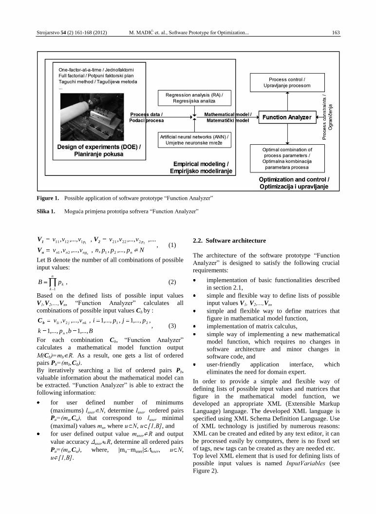
The motivation of this paper is to develop the software
prototype “Function Analyzer”, which can be used for
manufacturing process optimization and control. Based
on the loaded mathematical model, the prototype is able
to determine optimal input values of the process model
that satisfy the specified requirements. Figure 1
describes the potential usage of the software for
optimization and control of manufacturing processes.
“Function Analyzer” is based on iterative search of all
input values combinations, and is able to solve two
types of optimization problems: to determine the input
values that correspond to output extremes (minimum or
maximum) and to determine the input values that
correspond to user defined output with desired accuracy.
It enables a simple and flexible way of defining lists of
possible input values and mathematical model
functions. Due to user-friendly application interface,
“Function Analyzer” simplifies solving engineering
optimization problems and requires no expert
knowledge of optimization theory. Software architecture
is flexible and extendible, thus it can be improved for
solving multi-objective optimization problems.
2. Software prototype “Function Analyzer”
2.1. Software functionalities
The software prototype “Function Analyzer” enables
users to define the following parameters:
lists of possible input values V1,V2,...,Vn,
(equation (1)), and
mathematical model function M:Rn→R where
n N.
Strojarstvo 54 (2) 161-168 (2012) M. MADIĆ et. al., Software Prototype for Optimization... 163
Figure 1. Possible application of software prototype “Function Analyzer”
Slika 1. Moguća primjena prototipa softvera “Function Analyzer”
Np,...,p,p,n,v,...,v,v
,....v,...,v,v,v,...,v,v
nnpnn
pp
n 2121
2222111211 21
V
V V
n
21, (1)
Let B denote the number of all combinations of possible
input values:
n
k
kpB1
, (2)
Based on the defined lists of possible input values
V1,V2,...,Vn, “Function Analyzer” calculates all
combinations of possible input values Cb by :
C b
B,...,b,p,...,k
,p,...,j,p,...,i,v,...,v,v
n
nkji
11
11 2121, (3)
For each combination Cb, “Function Analyzer”
calculates a mathematical model function output
M(Cb)=mb R. As a result, one gets a list of ordered
pairs Pb=(mb,Cb). By iteratively searching a list of ordered pairs Pb,
valuable information about the mathematical model can
be extracted. “Function Analyzer” is able to extract the
following information:
for user defined number of minimums
(maximums) luser N, determine luser ordered pairs
Pu=(mu,Cu), that correspond to luser minimal
(maximal) values mu, where u N, u [1,B], and
for user defined output value muser R and output
value accuracy user R, determine all ordered pairs
Pu=(mu,Cu), where, |mu−muser| user, u N,
u [1,B].
2.2. Software architecture
The architecture of the software prototype “Function
Analyzer” is designed to satisfy the following crucial
requirements:
implementation of basic functionalities described
in section 2.1,
simple and flexible way to define lists of possible
input values V1, V2,...,Vn,
simple and flexible way to define matrices that
figure in mathematical model function,
implementation of matrix calculus,
simple way of implementing a new mathematical
model function, which requires no changes in
software architecture and minor changes in
software code, and
user-friendly application interface, which
eliminates the need for domain expert.
In order to provide a simple and flexible way of
defining lists of possible input values and matrices that
figure in the mathematical model function, we
developed an appropriate XML (Extensible Markup
Language) language. The developed XML language is
specified using XML Schema Definition Language. Use
of XML technology is justified by numerous reasons:
XML can be created and edited by any text editor, it can
be processed easily by computers, there is no fixed set
of tags, new tags can be created as they are needed etc.
Top level XML element that is used for defining lists of
possible input values is named InputVariables (see
Figure 2).
164 M. MADIĆ et. al., Software Prototype for Optimization... Strojarstvo 54 (2) 161-168 (2012)
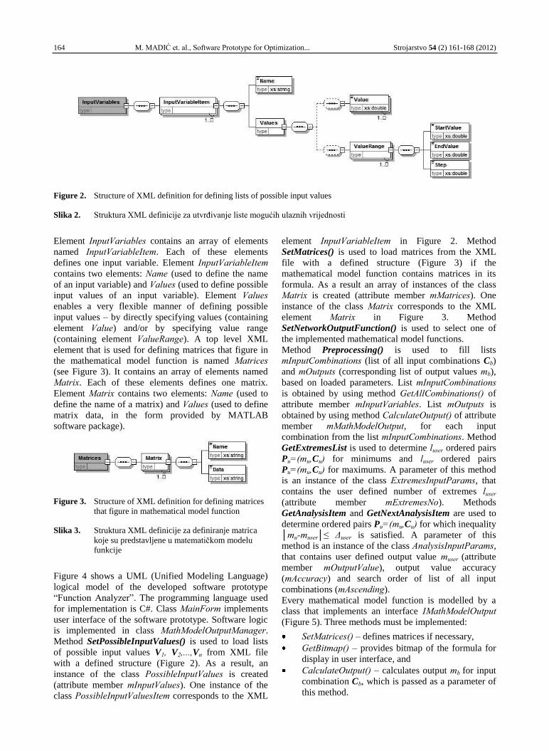
Figure 2. Structure of XML definition for defining lists of possible input values
Slika 2. Struktura XML definicije za utvrđivanje liste mogućih ulaznih vrijednosti
Element InputVariables contains an array of elements
named InputVariableItem. Each of these elements
defines one input variable. Element InputVariableItem
contains two elements: Name (used to define the name
of an input variable) and Values (used to define possible
input values of an input variable). Element Values
enables a very flexible manner of defining possible
input values – by directly specifying values (containing
element Value) and/or by specifying value range
(containing element ValueRange). A top level XML
element that is used for defining matrices that figure in
the mathematical model function is named Matrices
(see Figure 3). It contains an array of elements named
Matrix. Each of these elements defines one matrix.
Element Matrix contains two elements: Name (used to
define the name of a matrix) and Values (used to define
matrix data, in the form provided by MATLAB
software package).
Figure 3. Structure of XML definition for defining matrices
that figure in mathematical model function
Slika 3. Struktura XML definicije za definiranje matrica
koje su predstavljene u matematičkom modelu
funkcije
Figure 4 shows a UML (Unified Modeling Language)
logical model of the developed software prototype
“Function Analyzer”. The programming language used
for implementation is C#. Class MainForm implements
user interface of the software prototype. Software logic
is implemented in class MathModelOutputManager.
Method SetPossibleInputValues() is used to load lists
of possible input values V1, V2,...,Vn from XML file
with a defined structure (Figure 2). As a result, an
instance of the class PossibleInputValues is created
(attribute member mInputValues). One instance of the
class PossibleInputValuesItem corresponds to the XML
element InputVariableItem in Figure 2. Method
SetMatrices() is used to load matrices from the XML
file with a defined structure (Figure 3) if the
mathematical model function contains matrices in its
formula. As a result an array of instances of the class
Matrix is created (attribute member mMatrices). One
instance of the class Matrix corresponds to the XML
element Matrix in Figure 3. Method
SetNetworkOutputFunction() is used to select one of
the implemented mathematical model functions.
Method Preprocessing() is used to fill lists
mInputCombinations (list of all input combinations Cb)
and mOutputs (corresponding list of output values mb),
based on loaded parameters. List mInputCombinations
is obtained by using method GetAllCombinations() of
attribute member mInputVariables. List mOutputs is
obtained by using method CalculateOutput() of attribute
member mMathModelOutput, for each input
combination from the list mInputCombinations. Method
GetExtremesList is used to determine luser ordered pairs
Pu=(mu,Cu) for minimums and luser ordered pairs
Pu=(mu,Cu) for maximums. A parameter of this method
is an instance of the class ExtremesInputParams, that
contains the user defined number of extremes luser
(attribute member mExtremesNo). Methods
GetAnalysisItem and GetNextAnalysisItem are used to
determine ordered pairs Pu=(mu,Cu) for which inequality
│mu-muser│≤ Δuser is satisfied. A parameter of this
method is an instance of the class AnalysisInputParams,
that contains user defined output value muser (attribute
member mOutputValue), output value accuracy
(mAccuracy) and search order of list of all input
combinations (mAscending).
Every mathematical model function is modelled by a
class that implements an interface IMathModelOutput (Figure 5). Three methods must be implemented:
SetMatrices() – defines matrices if necessary,
GetBitmap() – provides bitmap of the formula for
display in user interface, and
CalculateOutput() – calculates output mb for input
combination Cb, which is passed as a parameter of
this method.
Strojarstvo 54 (2) 161-168 (2012) M. MADIĆ et. al., Software Prototype for Optimization... 165
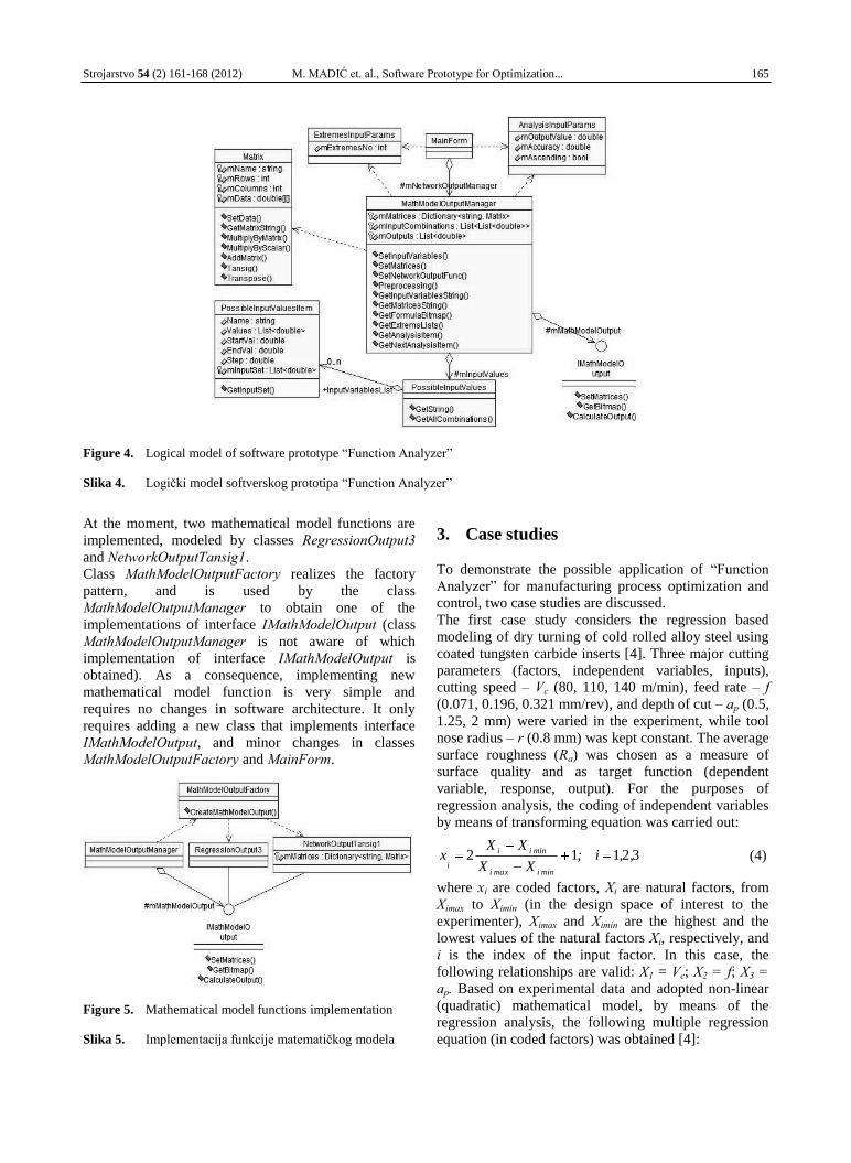
Figure 4. Logical model of software prototype “Function Analyzer”
Slika 4. Logički model softverskog prototipa “Function Analyzer”
At the moment, two mathematical model functions are
implemented, modeled by classes RegressionOutput3
and NetworkOutputTansig1.
Class MathModelOutputFactory realizes the factory
pattern, and is used by the class
MathModelOutputManager to obtain one of the
implementations of interface IMathModelOutput (class
MathModelOutputManager is not aware of which
implementation of interface IMathModelOutput is
obtained). As a consequence, implementing new
mathematical model function is very simple and
requires no changes in software architecture. It only
requires adding a new class that implements interface
IMathModelOutput, and minor changes in classes
MathModelOutputFactory and MainForm.
Figure 5. Mathematical model functions implementation
Slika 5. Implementacija funkcije matematičkog modela
3. Case studies
To demonstrate the possible application of “Function
Analyzer” for manufacturing process optimization and
control, two case studies are discussed.
The first case study considers the regression based
modeling of dry turning of cold rolled alloy steel using
coated tungsten carbide inserts [4]. Three major cutting
parameters (factors, independent variables, inputs),
cutting speed – Vc (80, 110, 140 m/min), feed rate – f (0.071, 0.196, 0.321 mm/rev), and depth of cut – ap (0.5,
1.25, 2 mm) were varied in the experiment, while tool
nose radius – r (0.8 mm) was kept constant. The average
surface roughness (Ra) was chosen as a measure of
surface quality and as target function (dependent
variable, response, output). For the purposes of
regression analysis, the coding of independent variables
by means of transforming equation was carried out:
32112 ,,i;XX
XXx
minimaxi
minii
i (4)
where xi are coded factors, Xi are natural factors, from
Ximax to Ximin (in the design space of interest to the
experimenter), Ximax and Ximin are the highest and the
lowest values of the natural factors Xi, respectively, and
i is the index of the input factor. In this case, the
following relationships are valid: X1 = Vc; X2 = f; X3 = ap. Based on experimental data and adopted non-linear
(quadratic) mathematical model, by means of the
regression analysis, the following multiple regression
equation (in coded factors) was obtained [4]:
166 M. MADIĆ et. al., Software Prototype for Optimization... Strojarstvo 54 (2) 161-168 (2012)
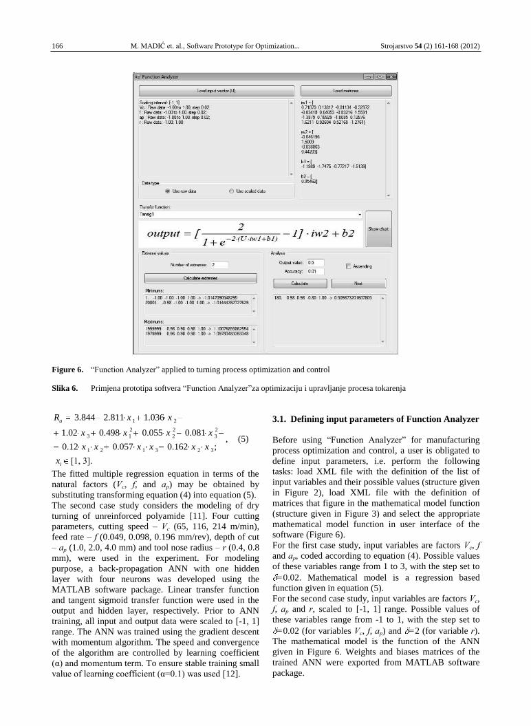
Figure 6. “Function Analyzer” applied to turning process optimization and control
Slika 6. Primjena prototipa softvera “Function Analyzer”za optimizaciju i upravljanje procesa tokarenja
;162.0057.012.0
081.0055.0498.002.1
036.1811.2844.3
323121
2
3
2
2
2
13
21
i
a
x
xxxxxx
xxxx
xxR
, (5)
The fitted multiple regression equation in terms of the
natural factors (Vc, f, and ap) may be obtained by
substituting transforming equation (4) into equation (5).
The second case study considers the modeling of dry
turning of unreinforced polyamide [11]. Four cutting
parameters, cutting speed – Vc (65, 116, 214 m/min),
feed rate – f (0.049, 0.098, 0.196 mm/rev), depth of cut
– ap (1.0, 2.0, 4.0 mm) and tool nose radius – r (0.4, 0.8
mm), were used in the experiment. For modeling
purpose, a back-propagation ANN with one hidden
layer with four neurons was developed using the
MATLAB software package. Linear transfer function
and tangent sigmoid transfer function were used in the
output and hidden layer, respectively. Prior to ANN
training, all input and output data were scaled to [-1, 1]
range. The ANN was trained using the gradient descent
with momentum algorithm. The speed and convergence
of the algorithm are controlled by learning coefficient
(α) and momentum term. To ensure stable training small
value of learning coefficient (α=0.1) was used [12].
3.1. Defining input parameters of Function Analyzer
Before using “Function Analyzer” for manufacturing
process optimization and control, a user is obligated to
define input parameters, i.e. perform the following
tasks: load XML file with the definition of the list of
input variables and their possible values (structure given
in Figure 2), load XML file with the definition of
matrices that figure in the mathematical model function
(structure given in Figure 3) and select the appropriate
mathematical model function in user interface of the
software (Figure 6).
For the first case study, input variables are factors Vc, f and ap, coded according to equation (4). Possible values
of these variables range from 1 to 3, with the step set to
=0.02. Mathematical model is a regression based
function given in equation (5).
For the second case study, input variables are factors Vc,
f, ap and r, scaled to [-1, 1] range. Possible values of
these variables range from -1 to 1, with the step set to
=0.02 (for variables Vc, f, ap) and =2 (for variable r).
The mathematical model is the function of the ANN
given in Figure 6. Weights and biases matrices of the
trained ANN were exported from MATLAB software
package.
[1, 3].
Strojarstvo 54 (2) 161-168 (2012) M. MADIĆ et. al., Software Prototype for Optimization... 167
3.2. Optimization
The main objective of these case studies was to
determine such a set of cutting conditions (Vc, f, ap, and
r) that satisfied the cutting parameters ranges to
minimize the Ra. The optimization results obtained
using “Function Analyzer” are given in Table 1.
Table 1. Optimization results
Tablica 1. Rezultati optimizacije
Vcopt
[m/min]
fopt
[mm/rev]
apopt
[mm]
ropt
[mm]
Ra(min) [μm]
Case
study 1 /
Studija
slučaja 1
136.4 0.071 0.5 0.8 1.568
Case
study 2 /
Studija
slučaja 2
65 0.049 1 0.8 0.6507
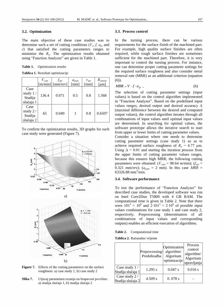
To confirm the optimization results, 3D graphs for each
case study were generated (Figure 7).
a)
b)
Figure 7. Effects of the cutting parameters on the surface
roughness: a) case study 1, b) case study 2
Slika 7. Utjecaj parametara rezanja na hrapavost površine:
a) studija slučaja 1, b) studija slučaja 2
3.3. Process control
In the turning process, there can be various
requirements for the surface finish of the machined part.
For example, high quality surface finishes are often
required, while rough surface finishes are sometimes
sufficient for the machined part. Therefore, it is very
important to control the turning process. For instance,
one can determine proper cutting parameter settings for
the required surface roughness and also consider metal
removal rate (MRR) as an additional criterion (equation
(6)).
pafVMRR , (6)
The selection of cutting parameter settings (input
values) is based on the control algorithm implemented
in “Function Analyzer”. Based on the predefined input
values ranges, desired output and desired accuracy Δ
(maximal difference between the desired and computed
output values), the control algorithm iterates through all
combinations of input values until optimal input values
are determined. In searching for optimal values, the
software prototype allows the iterative search to start
from upper or lower limits of cutting parameter values.
Consider a situation where one needs to determine
cutting parameter settings (case study 1) so as to
achieve required surface roughness of Ra = 4.77 µm.
Using Δ = 0.01 and starting the iteration process from
the upper limits of cutting parameter values ranges,
because this ensures high MRR, the following cutting
parameters were obtained: (Vcopt = 98.64 m/min); (fopt =
0.321 mm/rev); (apopt = 2 mm). In this case MRR =
63326.88 mm3/min.
3.4. Software performance
To test the performance of “Function Analyzer” for
described case studies, the developed software was run
on Intel Core2Duo T5800 with 4 GB RAM. The
computational time is given in Table 2. Note that there
were 1013 ≈ 10
6 and 2·101
3 ≈ 2·10
6 of possible input
values combinations for case study 1 and case study 2,
respectively. Preprocessing (determination of all
combinations of input values and corresponding
outputs) enables an efficient execution of algorithms.
Table 2. Computational time
Tablica 2. Računalno vrijeme
Preprocessing/
Predobradba
Optimization
algorithm/
Algoritam
optimizacije
Process
control
algorithm/
Algoritam
upravljanja
Case study 1 /
Studija slučaja 1 1.295 s 0.047 s 0.016 s
Case study 2 /
Studija slučaja 2 4.509 s 0. 078 s -
168 M. MADIĆ et. al., Software Prototype for Optimization... Strojarstvo 54 (2) 161-168 (2012)
4. Conclusion
In this paper, the software prototype “Function
Analyzer” is proposed for single objective optimization
of manufacturing processes parameters. “Function
Analyzer” is based on the mathematical iterative search
of all input values combinations, and is able to solve
two types of optimization problems: to determine the
input values that correspond to output extremes
(minimum or maximum) and to determine the input
values that correspond to user defined output with
desired accuracy. “Function Analyzer” provides a
simple and flexible way of defining lists of possible
input values. It enables working with mathematical
models based on RA and ANN, but additional models
can easily be implemented. Due to user-friendly
application interface, “Function Analyzer” simplifies
solving engineering optimization problems and requires
no expert knowledge of optimization theory. Although
based on iterative search, the developed software
prototype is efficient even for large sets of possible
input. Additionally, setting numerous optimization
parameters and initial search points is avoided.
The abilities of software prototype “Function Analyzer”
for optimization and control of the turning process were
illustrated on two case studies using regression and
artificial neural network based models.
Future work could be directed toward solving multi-
objective optimization problems in manufacturing
processes and implementation of the software to real-
time problems.
Acknowledgements
This paper is part of project TR35034 funded by the
Ministry of Education and Science of the Republic of
Serbia.
REFERENCES
[1] ČUŠ, F.; MILFELNER, M.; BALIČ, J.: An intelligent system for monitoring and optimization of ball-end milling process, Journal of Materials
Processing Technology, 175 (2006) 1-3, 90-97.
[2] LIAO, T.W.; CHEN, L.J.: Manufacturing process modeling and optimization based on multi-layer perceptron network, Journal of Manufacturing
Science and Engineering, 120 (1998) 1, 109-119.
[3] GEČEVSKA, V.; ČUŠ, F.: Intelligent process planning for competitive engineering, Strojarstvo,
52 (2010) 1, 33-41.
[4] TANIKIĆ, D.; MARINKOVIĆ, V.: Modelling and optimization of the surface roughness in the dry turning of the cold rolled alloyed steel using regression analysis, Journal of the Brazilian
Society of Mechanical Sciences and Engineering,
34 (2012) 1, 41-48.
[5] BAJIĆ, D.; JOZIĆ, S.; PODRUG, S.: Design of experiment’s application in the optimization of
milling process, Metalurgija, 49 (2010) 2, 123-
126.
[6] JURKOVIĆ, Z.; BREZOČNIK, M.; GRIZELJ, B.;
MANDIĆ, V.: Optimization of extrusion process by genetic algorithms and conventional techniques, Technical Gazette, 16 (2009) 4, 27-33.
[7] LEE, B.J.; TARNG, Y.S.: Cutting-parameter selection for maximizing production rate or minimizing production cost in multistage turning operations, Journal of Materials Processing
Technology, 105 (2000) 1-2, 61-66.
[8] YANG, S.-H.; SRINIVAS, J.; MOHAN, S.; LEE,
D.-M.; BALAJI, S.: Optimization of electric discharge machining using simulated annealing,
Journal of Materials Processing Technology, 209
(2009) 9, 4471-4475.
[9] KARPAT, Y.; ÖZEL, T.: Multi-objective optimization for turning processes using neural network modeling and dynamic-neighborhood particle swarm optimization, International Journal
of Advanced Manufacturing Technology, 35
(2007) 3-4, 234-247.
[10] HIMMELBLAU, D.M.: Applied nonlinear programming, McGraw-Hill Book Company, New
York, 1972.
[11] LAZAREVIĆ, D.; JANKOVIĆ, P.; MADIĆ, M.;
LAZAREVIĆ, A.: Study on surface roughness minimization in turning of polyamide PA-6 using Taguchi method, Proceedings of 34
th International
Conference on Production Engineering, Niš, 2011.
[12] ŠIMUNOVIĆ, K.; ŠIMUNOVIĆ, G.; ŠARIĆ, T.:
Application of artificial neural networks to multiple criteria inventory classification,
Strojarstvo, 51 (2009) 4, 313-321.