software realization on the msc nanorisc hardware...
TRANSCRIPT

20 Telfor Journal, Vol. 7, No. 1, 2015.
1 Abstract — This paper describes software realization and
its implementation for the communication, according to the IEC61850 standard, between the module for monitoring teleprotection devices and the control/monitoring server in a power substation. Teleprotection devices have an important role in the transmission of messages for power line section tripping. The software is implemented on the “MSC nanoRISC-S3C2416 MB2” hardware platform type, which belongs to the COM (computer on module) systems.
Keywords — communication, electric power utility, IEC61850, nanoRISC-S3C2416, substation, software, teleprotection.
I. INTRODUCTION
NTIL the advent of digital communication devices, communications were the bottleneck in an electric
power system. Digitalization solved the problem of the communication bandwidth, but the problem of managing a large number of different devices has appeared, as well as enabling the various devices to communicate with each other. Therefore the need for a new communication model appears, which has been developed and standardized as the IEC61850 standard (Communication Networks and Systems in Substations) [1]. The main purpose of the new standard is to enable products from different vendors to be easily integrated to one substation infrastructure. This is done by defining the substation bus (Fig. 1) [2]. The IEC 61850 standard has been created to be functionally flexible and expandable. Advanced functionality and data transfer methods are one step closer to the future Smart Grids.
The standard specifies the following: 1. Object models of data that describe the information
obtained from various primary devices, as well as automatic functions of the substation,
Paper received March 20, 2015; accepted May 20, 2015. Date of
publication July 15, 2015. The associate editor coordinating the review of this manuscript and approving it for publication was Prof. Zorica Nikolić.
This paper is a revised and expanded version of the paper presented
at the 22th Telecommunications Forum TELFOR 2014.
This work received partial support from the Serbian Ministry of Education, Science and Tehnological Development, project TR32037.
Anka, V. Kabović, (author for contacts), Institute „Mihajlo Pupin“,
Volgina 15, 11060 Belgrade, Serbia (phone: 381-63-8987215, e-mail: [email protected] ).
Milenko, M. Kabović, Institute „Mihajlo Pupin“, Volgina 15, 11060 Belgrade, Serbia ( e-mail: [email protected] ).
Vladimir, V. Čelebić, Institute „Mihajlo Pupin“, Volgina 15, 11060 Belgrade, Serbia (e-mail: [email protected] ).
2. Communication interfaces and messages that are exchanged between Intelligent Electronic Devices (IEDs) in the substation, and
3. Configuration language which describes IEDs, and exchanging configuration information.
Communication is done via Ethernet, and the types of the data exchanged are:
• Requests-answers over the abstract communication interface which serves for obtaining data from or sending data to the devices,
• Digitalized samples of analog energy data, and • Finally, Generic Substation Events (GSE) type
messages, which serve for the transmission of substation events [3]-[4].
Fig. 1 shows the substation architecture where the IEC61850 standard is implemented. As can be seen from Fig. 1, IEDs get digitalized data from the power grid via a process bus and merge units. Communication between them is done via a substation bus that is a 10/100/1000 Mbps Ethernet. Substation also has a Human Management Interface (HMI) through which one can get information from the devices or send control messages.
Fig. 1. IEC61850 substation architecture.
Realized software supports messages that are exchanged over the Abstract Communication Service Interface (ACSI) (defined in part 7-2 of the Standard) [4]. The specific syntax and encoding of the messages that carry service parameters and how they are passed through the network are defined in the Specific Communication Service Mapping (SCSM). Part 8-1 of the standard defines the mapping of the ACSI services to the Manufacturing Message Specification (MMS) messages and other provisions like Transmission Control (TCP/IP) and Ethernet protocols. This is shown in Fig. 2. MMS messages (supported by the software) enable obtaining the
Software Realization on the MSC nanoRISC Hardware Platform, for Communication
According to the IEC61850 Standard
Anka V. Kabović, Milenko M. Kabović, and Vladimir V. Čelebić
U

Kabović et al.: Software Realization for Communication According to the IEC61850 Standard 21
status of the devices, the configuration of certain parameters, and an overview of the working history by requesting reports or log files. Described software does not support the processing of Generic Object Oriented Substation Event (GOOSE) messages, which is intended for special application, see Fig. 2.
The first part of the paper describes the software structure and functionality, whose main task is collecting data from the teleprotection devices [5] in the substation, as well as sending data to the server for monitoring. Software supports a large part of the message set which is defined in the IEC61850-8-1. The second part of the paper describes software implementation on a particular type of module (MSC nanoRISC-S3C2416 MB2), which belongs to the class of computers on the module. The characteristics of these systems are: they are based on a complex processor of the type S3C2416, they have DRAM, NAND flash and SD/MMC memories, as well as input/output controllers such as Ethernet controller, controller for serial RS232 interface, etc. This sort of hardware platform is suitable for implementing complex software on small-size hardware, with a low power consumption.
This solution enables monitoring several devices of the same type (in this case teleprotection), storing more data from these devices, as well as processing a larger set of MMS messages. The software is currently working on a laboratory model.
Fig. 2. Specific communication service mapping.
II. DESCRIPTION OF SOFTWARE REALIZATION
A. Description of the main program
Software is written in C language, and includes the main program function and a large set of auxiliary functions. The basic tasks of the main program are:
• Initialization of the nanoRISC module’s file system with the files and catalogs which are required for monitoring of the teleprotection devices in the substation.
• Sending the module’s IP address to the devices from the local substation’s network, using either a multicast or unicast message.
• Opening TCP/IP ports and listening to the client
demands for establishing connections, whereby clients are teleprotection devices or server for monitoring.
• Acceptance of the client’s request to establish a connection, and exchanging data with them.
• If the data transfer is completed with the client, the existing TCP/IP connection is closed, and the program enters a waiting state; the new demand for establishing a connection. If there is a requirement for closing the TCP/IP port, it is closed. The program enters a post initialization state, where it sends the module’s IP address using User Datagram protocol (UDP) protocol.
The flowchart of the main program is shown in Fig. 3.
Fig. 3. Flowchart of the main program
(module “SendRecData“).
Two separate folders for each device are formed in the initialization function of nanoRISC module’s file system. One of these folders is used for storing files with the data obtained from the teleprotection devices, and the other (having the same structure) is used for storing data intended for the server. Each of these two folders has five subfolders: Physical Device Information (LPHD), Logical
22 Telfor Journal, Vol. 7, No. 1, 2015.
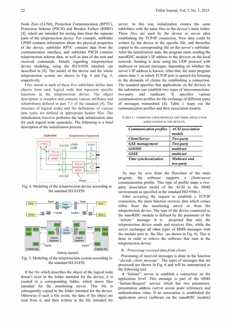
Node Zero (LLN0), Protection Communication (RPTC), Protection Scheme (PSCH) and Breaker Failure (RBRF) [4], which are intended for storing data from the separate parts of the teleprotection device. For example, subfolder LPHD contains information about the physical properties of the device, subfolder RPTC contains data from the communication interface, and subfolder PSCH contains teleprotection scheme data, as well as data of the sent and received commands. Details regarding teleprotection device modeling, using the IEC61850 standard, are described in [4]. The model of the device and the whole teleprotection system are shown in Fig. 4 and Fig. 5, respectively.
Files stored in each of these five subfolders define data objects from each logical node that represent specific functions in the teleprotection device. The object description is complex and contains various attributes and subattributes defined in part 7-3 of the standard [4]. The structure of logical nodes and the definitions of various data types are defined in appropriate header files. The initialization function performs the task initialization data for each logical node separately. The following is a brief description of the initialization process.
Fig. 4. Modeling of the teleprotection device according to
the standard IEC61850.
Fig. 5. Modeling of the teleprotection system according to
the standard IEC61850.
If the file which describes the object of the logical node doesn’t exist in the folder intended for the device, it is created in a corresponding folder, which stores files intended for the monitoring server. This file is subsequently copied to the folder intended for the device. Otherwise if such a file exists, the data of the object are read from it, and then written in the file intended for
server. In this way initialization creates the same subfolders with the same files in the device’s main folder. These files are used by the device or server after establishing the TCP/IP connection. New data could be written by the device in the specific file, and thereafter copied to the corresponding file on the server’s subfolder. After the initialization state, the program starts sending the nanoRISC module’s IP address to the devices on the local network. Sending is done using the UDP protocol with multicast or unicast messages, depending on whether the server’s IP address is known. After that, the main program enters state 3, in which TCP/IP port is opened for listening to the demands of clients for establishing a connection. The standard specifies that applications on the devices in the substation can establish two types of interconnections: two-party and multicast. It specifies various communication profiles for the exchange of different types of messages transmitted [4]. Table 1 maps out the communication profiles and their association models.
TABLE 1: COMMUNICATION PROFILES AND THEIR APPLICATION
ASSOCIATIONS IN THE DEVICES.
Communication profiles ACSI association models
Client/Server Two-party GSE management Two-party GOOSE multicast GSSE multicast Time synchronization Multicast and
two-party
As may be seen from the flowchart of the main program, the software supports a client/server communication profile. This type of profile maps a two-party association model of the ACSI to the MMS environment as specified in the standard ISO 9506-1.
After accepting the request to establish a TCP/IP connection, the main function receives data which comes either from the monitoring server or from the teleprotection device. The type of the device connected to the nanoRISC module is defined by the parameter of the “initiate” message. It is projected that only the teleprotection device sends and receives files, while the server exchanges all other types of MMS messages with the module next to the files (as shown in Fig. 6). This is done in order to relieve the software that runs in the teleprotection device.
B. Processing received data from clients
Processing of received messages is done in the function “decode_client_message”. The types of messages that are processed are shown in Fig. 6 and will be summarized in the following text:
• “Initiate”: serves to establish a connection on the application level. This message is part of the MMS “Initiate-Request” service which has two parameters: presentation address (server access point reference), and authentication value. If an association is established the application server (software on the nanoRISC module)

Kabović et al.: Software Realization for Communication According to the IEC61850 Standard 23
sends a response with a parameter which represents the association’s identification.
• “Abort”: requires violent completion of the client/server association.
• “Conclude”: requires normal completion of the client/server association.
• “GetNameList”: requests the content of the main folder of the device or logical node, depending on the parameter type. When the parameter of service is the name of the device, the MMS service is created by mapping the ACSI request “GetLogicalDeviceDirectory”. However, when the parameter is the name of the logical node with the name of the data class being requested, the MMS service is created by mapping the ACSI request “GetLogicalNodeDirectory”. The classes of data defined in the ACSI which could be requested are: the class that represents the data object, the data set, control blocks, or log files.
Fig. 6. Types of MMS messages to be processed in the
function “decode_client_message”.
• “Read”: depending on the parameter requests: reads the value of the individual attribute of the data object from the logical node, reads values of all the data object’s attributes, reads only the values of some attributes of the data object that have the given functional constraint, and as the last option, reads the values of attributes of all objects that have the given functional constraint from the logical node. For the last option, the value of the parameter is the name of the logical node. This message is the part of the MMS read service that could be created by mapping the ACSI “GetDataValues” or “GetDataSetValues” service, and other services that read the values of various data types from the logical node.
• “Write”: depending on the parameter type requests:
writes the new value of the individual attributes of the data object, writes the new values of all attributes of a particular object, and finally writes the new values of the attributes of the data object that have a given functional constraint. The parameter structure is similar to the “read” message. This message is part of the MMS write service that could be created by mapping the ACSI “SetDataValues” service, and other services that write the values of various types of data in the logical node. Separate functions are written for reading and writing certain classes of objects.
• “GetVariableAccessAttributes” has a reference to the data object as a parameter type. It serves for reading the names of all attributes of the referenced data object. This message is the part of the MMS service that was created by mapping the ACSI “GetDataDirectory” service.
• “GetNamedVariableListAttributes” has the parameter which represents the reference to the data object of the “dataSet” type. This message requires the references of the data objects that makeup the data set. This message is part of the MMS service created by mapping the ACSI “GetDataSetDirectory” service.
Fig.7. Basic building blocks for reporting and logging.
• Messages that are related with read/write operations
of the control blocks for the “log” files, and for searching data from the “log” files: ACSI services that work with the control block of the log files are mapped to the “read/write” messages of the log control block parameters. ACSI services for reading log files such as „QueryLogbyTime“ and „QueryLogAfter“, are mapped to the MMS „ReadJournal“ service. Fig. 7 shows the basic building blocks for reporting and logging functions as defined in part 7-2 of the standard [4].
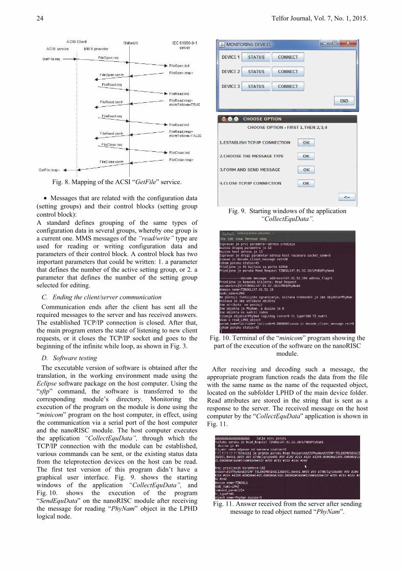
• Messages that are related to working with general purpose files: ACSI communication services that work with files are mapped to one or more MMS services. In this way ACSI service “GetFile” is mapped to the sequence of MMS services: “FileOpen”, “FileRead” and “FileClose”. ACSI service “GetFileAttributes” is mapped to the MMS service “FileDirectory”. With this service, the contents of the folder with files and their attributes can be obtained. There are also services for deleting and writing files. In Fig. 8 mapping of the ACSI service “GetFile” is shown.
24 Telfor Journal, Vol. 7, No. 1, 2015.
Fig. 8. Mapping of the ACSI “GetFile” service.
• Messages that are related with the configuration data
(setting groups) and their control blocks (setting group control block): A standard defines grouping of the same types of configuration data in several groups, whereby one group is a current one. MMS messages of the “read/write” type are used for reading or writing configuration data and parameters of their control block. A control block has two important parameters that could be written: 1. a parameter that defines the number of the active setting group, or 2. a parameter that defines the number of the setting group selected for editing.
C. Ending the client/server communication
Communication ends after the client has sent all the required messages to the server and has received answers. The established TCP/IP connection is closed. After that, the main program enters the state of listening to new client requests, or it closes the TCP/IP socket and goes to the beginning of the infinite while loop, as shown in Fig. 3.
D. Software testing
The executable version of software is obtained after the translation, in the working environment made using the Eclipse software package on the host computer. Using the “sftp” command, the software is transferred to the corresponding module’s directory. Monitoring the execution of the program on the module is done using the “minicom” program on the host computer, in effect, using the communication via a serial port of the host computer and the nanoRISC module. The host computer executes the application “CollectEquData”, through which the TCP/IP connection with the module can be established, various commands can be sent, or the existing status data from the teleprotection devices on the host can be read. The first test version of this program didn’t have a graphical user interface. Fig. 9. shows the starting windows of the application “CollectEquData”, and Fig. 10. shows the execution of the program “SendEquData” on the nanoRISC module after receiving the message for reading “PhyNam” object in the LPHD logical node.
Fig. 9. Starting windows of the application
“CollectEquData”.
Fig. 10. Terminal of the “minicom” program showing the
part of the execution of the software on the nanoRISC module.
After receiving and decoding such a message, the
appropriate program function reads the data from the file with the same name as the name of the requested object, located on the subfolder LPHD of the main device folder. Read attributes are stored in the string that is sent as a response to the server. The received message on the host computer by the “CollectEquData” application is shown in Fig. 11.
Fig. 11. Answer received from the server after sending
message to read object named “PhyNam”.

Kabović et al.: Software Realization for Communication According to the IEC61850 Standard 25
III. SOFTWARE IMPLEMENTATION ON THE MSC
NANORISC-S3C2416MB2 MODULE
A. Description of the MSC nanoRISC-S3C2416MB2 module
The module which is shown in Fig. 12 consists of two main parts:
• Base plate (motherboard) with the name MSC nanoRISC MB2, consisting of several interfaces such as: LAN, USB, graphical RGB 18/24 bits, LVDS interface, serial ports of the type UART, CAN, I2C and SPI.
• Processor board with the name nanoRISC S3C2416, which represents the module with the Samsung ARM9 processor that has a high performance and low power consumption. Processor S3C2416 works with the 400 MHz clock, dynamic RAM memory with the capacity of 64 MB, NAND flash memory with the capacity of 128MB and SD/MMC memory. Work of the Ethernet interface is supported by the controller of type MICROCHIP ENC24J600.
Fig. 12. Picture of the module MSC
nanoRISC-S3C2416 MB2. Software that supports the operation of the module
consists of the following parts: 1. Software for starting the operating system (u-boot-
1.3.4-samsung-s3c2416), 2. Kernel of the type „embedded linux“ (linux-2.6.37.6-
nanoRISC-S3C2416), 3. File system of the type „buildroot“ (buildroot-
2011.02-nanorisc-wgle...), as well as 4. The tools that serve to create the executable versions
of the parts of the operating system. Making and installing parts of the operating system on the SD memory card is done on the host computer in the working environment of the Ubuntu Linux operating system version 10.4. The process of making the work environment, as well as the parts of the operating system was carried out according
to the documentation obtained from the manufacturer [6] and [7]. Here it will be mentioned that it is necessary to create a folder, which serves as the main folder for the installation of the software packages with the source code for making the parts of the module’s operating system. Also it is necessary to create some additional folders for keeping newly made versions of the “bootloader”, Linux kernel and file system image.
IV. CONCLUSION
This paper describes the software realization for communication according to the IEC61850 standard, which enables monitoring of one or multiple teleprotection devices, as well as the realization of more communication messages than when the software is running in the teleprotection device. The module enables storage of large amounts of data from the teleprotection devices in the substation, as well as monitoring devices with no greater burden of their software. Laboratory tests have shown that nanoRISC-S3C2416 can be used as the platform for complicated software applications, so it could be used as the central processor or control module in the new version of the teleprotection device [5]. The operating system of the module can be reconfigured – changed in order to install desirable options, and various ports enable additional functionality. Future work will be focused on testing the operation of the program in real terms, and the implementation of some additional commands like “SetFile” command and commands for creating and deleting data sets.
REFERENCES
[1] Drew Baigent, Mark Adamiak, Ralph Mackiewich, “IEC61850 Communication Networks and Systems in Substations: An Overview for Users”,SIPSEP 2004.
[2] IEC 61850-1: Communication Networks and Systems in Substations, Part 1: Introduction and Overview, 2003.
[3] C.Brunner, “IEC 61850 Process connection - a smart solution to connect the primary equipment to the substation automation system”, Presented at the PSCC (15th Power System Computation
Conference), Liege/Belgium, 2005. [4] International Standard for Communication Networks and Systems
in Substations, IEC81850 Part 7-1, 7-2, 7-3, 7-4, 8-1, 90-1, IEC 2003, Switzerland.
[5] V.Čеlеbić, Ј.Gајicа, I.Sаlоm, „Multiplexer equipment for transmission of teleprotection signal, application, requirements, place in the power system“, in Proc. D2 Colloquium CIGRE Serbia, Belgrade 2010., D2 I01, pp1-11.
[6] “MSC nanoRISC S3C2416 User’s Manual” MSC Vertriebs Gmbh, Rev. 0.2, March 2011.
[7] “MSC nanoRISC Main Board 2 User’s Manual”, MSC Vertriebs Gmbh, Rev. 0.3, April 2011.