soil improvement by vacuum preloading for …geotekindo.com/download/soilimprovementbyvacuum... ·...
TRANSCRIPT
18th Southeast Asian Geotechnical & Inaugural AGSSEA Conference 29 - 31 May 2013, Singapore
Leung, Goh & Shen (eds)
SOIL IMPROVEMENT BY VACUUM PRELOADING FOR A POWER PLANT PROJECT IN VIETNAM
GOUW TJIE-LIONG1
Civil Engineering, Binus Univeristy, Indonesia, [email protected]
LIU YU2 PT.Geotekindo, Indonesia, [email protected]
ABSTRACT: A power plant project in South Vietnam was to be constructed on 16-30m depth very soft muddy clay layer. The project covered an area of 25.3 hectare. The very soft clay layer had a natural water content of around 58%, initial void ratio 1.594, and compression index 0.615. Vacuum preloading with an average PVD length of 26m and vacuum pressure of more than 80 kPa, was employed to improve the soft soil. The vacuum degree, surface and subsoil settlement, pore water pressure and lateral displacement were carefully monitored during the preloading period. After the vacuum preloading period of 117 - 150 days, ground surface settlement of 1.254-1.655 m correspond to a degree of consolidation over 90% was achieved. The maximum lateral displacement was 176mm in the direction towards the improved area. The after treatment Vane Shear Test yields undrained shear strength, Su, is 40 ~ 70 kPa. KEYWORDS: Vacuum preloading; soft muddy clay; vacuum degree; ground surface settlement; pore water pressure; lateral displacement.
INTRODUCTION
The proposed power plant is located at the entrance between two tributaries of Mekong River flowing into South China Sea. The landform is a typical delta formed by sea-land interaction and flood land at an edge of alluvial plain. Soil investigation result indicated that there is an extremely soft muddy clay layer with a thickness of 16.0~30.0 m.
Vacuum preloading method was adopted to improve soft soil in this project which covered an
area of 25.3 hectare, divided to 10 zones during construction. The vacuum degree, surface and subsoil settlement, pore water pressure and lateral displacement were carefully monitored during the preloading period. The mechanism of vacuum preloading method and the monitoring data are presented and discussed in this paper.
STRATUM CHARACTERISTICS
According to the survey result, from 100m depth to the ground surface, all deposits are of Quaternary age. The subsoils where vacuum preloading soil improvement was applied were described below (from top to bottom):
Layer ①-Backfill layer: embanked soil and late marine deposits. Light grey, hoar, loose,
slightly dense, mainly filled with silty sand, newly formed and untreated, with thickness from 0.30m to 7.80m.
Layer ②-Clay: Swamp and marine deposits. Dark grey, brownish grey, very soft, liquid-
plastic, contain large amount of organic matter and shell pieces, partially with lenses and pockets

of fine sand, with thickness from 17.5m to 25.0m. Initial soil properties of layer ② are listed in Table 1. Thickness contour of layer ② is shown in Fig 1.
Sub-layer ②a-Fine sand: Marine deposits, dark grey, black, loose, partially slightly dense.
This layer is exposed in most boreholes and the distribution is continuous at 6.00 ~ 10.00m depth under the ground. The thickness is normally 0.50m~3.00m and maximum is 13.4m.
Layer ③-Fine sand: Marine deposits, light grey, brown yellow, medium dense, partially
slightly dense or dense. Below layer ③ is stiff ~ very stiff soil.
Table 1. Original soil properties of layer ②.
Items Unit Average value Water content w % 57.9 Unit weight γw g/cm3 16.3 Void ratio e0 1.594
Compressibility Index Cc 0.615 Coefficient of consolidation 10-3cm2/s Cv 0.74
Ch 0.93
Fig 1. Thickness contour of the soft soil.
DESIGN & CONSTRUCTION
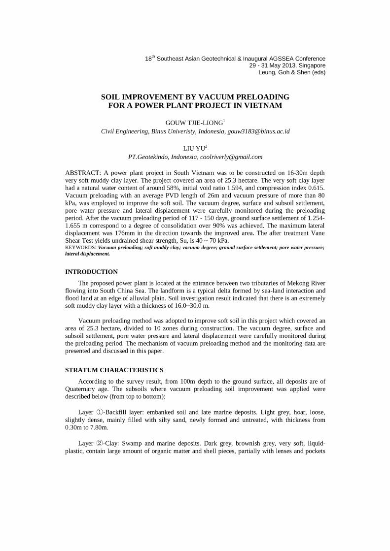
Vacuum preloading method utilizes atmospheric pressure as surcharge load to accelerate soil consolidation. Its principle is presented in Fig 2.
Basically, whole vacuum preloading system consists of drainage system, sealing system and
vacuum pumps. Vacuum pressure, generated in vacuum pumps, spreads into soils along drainage
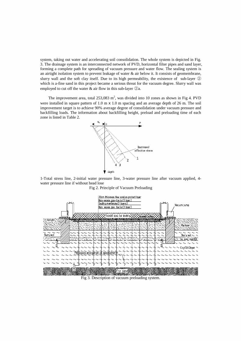
system, taking out water and accelerating soil consolidation. The whole system is depicted in Fig. 3. The drainage system is an interconnected network of PVD, horizontal filter pipes and sand layer, forming a complete path for spreading of vacuum pressure and water flow. The sealing system is an airtight isolation system to prevent leakage of water & air below it. It consists of geomembrane, slurry wall and the soft clay itself. Due to its high permeability, the existence of sub-layer ② which is a-fine sand in this project became a serious threat for the vacuum degree. Slurry wall was employed to cut off the water & air flow in this sub-layer ②a.
The improvement area, total 253,083 m2, was divided into 10 zones as shown in Fig 4. PVD
were installed in square pattern of 1.0 m x 1.0 m spacing and an average depth of 26 m. The soil improvement target is to achieve 90% average degree of consolidation under vacuum pressure and backfilling loads. The information about backfilling height, preload and preloading time of each zone is listed in Table 2.
1-Total stress line, 2-initial water pressure line, 3-water pressure line after vacuum applied, 4-water pressure line if without head lose
Fig 2. Principle of Vacuum Preloading
Fig 3. Description of vacuum preloading system.
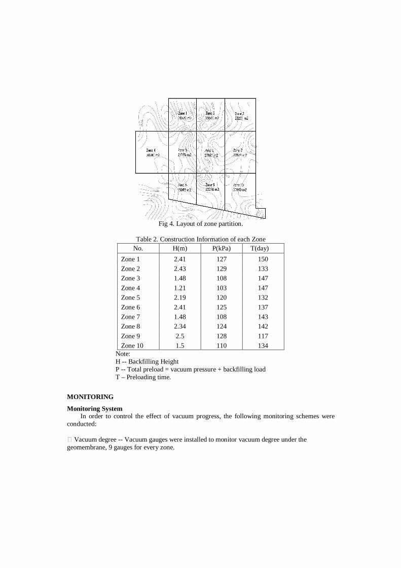
Fig 4. Layout of zone partition.
Table 2. Construction Information of each Zone
No. H(m) P(kPa) T(day) Zone 1 2.41 127 150 Zone 2 2.43 129 133 Zone 3 1.48 108 147 Zone 4 1.21 103 147 Zone 5 2.19 120 132 Zone 6 2.41 125 137 Zone 7 1.48 108 143 Zone 8 2.34 124 142 Zone 9 2.5 128 117 Zone 10 1.5 110 134
Note: H -- Backfilling Height P -- Total preload = vacuum pressure + backfilling load T – Preloading time.
MONITORING
Monitoring System In order to control the effect of vacuum progress, the following monitoring schemes were
conducted:
Vacuum degree -- Vacuum gauges were installed to monitor vacuum degree under the geomembrane, 9 gauges for every zone.
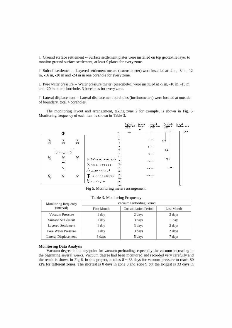
Ground surface settlement -- Surface settlement plates were installed on top geotextile layer to monitor ground surface settlement, at least 9 plates for every zone.
Subsoil settlement -- Layered settlement meters (extensometer) were installed at -4 m, -8 m, -12 m, -16 m, -20 m and -24 m in one borehole for every zone.
Pore water pressure -- Water pressure meter (piezometer) were installed at -5 m, -10 m, -15 m and -20 m in one borehole, 3 boreholes for every zone.
Lateral displacement -- Lateral displacement boreholes (inclinometers) were located at outside of boundary, total 4 boreholes.
The monitoring layout and arrangement, taking zone 2 for example, is shown in Fig. 5. Monitoring frequency of each item is shown in Table 3.
Fig 5. Monitoring meters arrangement.
Table 3. Monitoring Frequency
Monitoring frequency (interval)
Vacuum Preloading Period First Month Consolidation Period Last Month
Vacuum Pressure 1 day 2 days 2 days Surface Settlement 1 day 3 days 1 day Layered Settlement 1 day 3 days 2 days Pore Water Pressure 1 day 3 days 2 days Lateral Displacement 3 days 5 days 7 days
Monitoring Data Analysis
Vacuum degree is the key-point for vacuum preloading, especially the vacuum increasing in the beginning several weeks. Vacuum degree had been monitored and recorded very carefully and the result is shown in Fig 6. In this project, it takes 8 ~ 33 days for vacuum pressure to reach 80 kPa for different zones. The shortest is 8 days in zone 8 and zone 9 but the longest is 33 days in

zone 6. Basically, after the beginning period, the vacuum pressures were maintained over 80 kPa except some power off accidents which are clearly showed in Fig 6.
Asaoka method was used to calculate consolidation degree for each zone based on surface settlement monitoring data. After 117 ~ 150 days preloading, all zones had reached consolidation degree requirement with surface settlement ranging from 1254 mm to 1655 mm. The average consolidation degrees are listed in Table 4.
0 30 60 90 120 1500
20
40
60
80
Vac
uum
pre
ssur
e(kP
a)
Time (Day)
Zone 1 Zone 2 Zone 3 Zone 4 Zone 5 Zone 6 Zone 7 Zone 8 Zone 9 Zone 10
Fig 6. Vacuum degree curves. Fig 7. Contour of surface settlement.
Table 4. Average Consolidation Degrees No. T day) P kPa) Scon (mm) U
Zone 1 150 127 1454 97% Zone 2 133 129 1445 97% Zone 3 147 108 1254 91% Zone 4 147 103 1458 99% Zone 5 132 120 1607 99% Zone 6 137 125 1655 99% Zone 7 143 108 1295 99% Zone 8 142 124 1353 99% Zone 9 117 128 1496 96% Zone 10 134 110 1291 99%
Notes: Scon -- Surface settlement during preloading. U -- Average consolidation degree (by Asaoka method).
Among the 10 zones, zone 6, zone 2 and zone 3 are typical zones which represent middle, side and corner zone respectively. Therefore, the monitoring data in these 3 zones will be further analyzed.
Power off
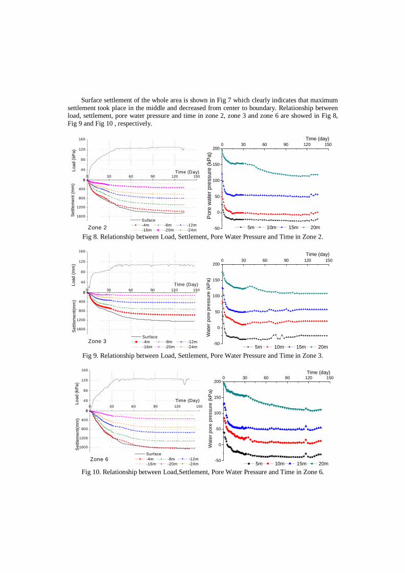
Surface settlement of the whole area is shown in Fig 7 which clearly indicates that maximum settlement took place in the middle and decreased from center to boundary. Relationship between load, settlement, pore water pressure and time in zone 2, zone 3 and zone 6 are showed in Fig 8, Fig 9 and Fig 10 , respectively.
1600
1200
800
400
00 30 60 90 120 150
Suface -4m -8m -12m -16m -20m -24m
Settl
emen
t (m
m)
0
40
80
120
160
Zone 2
Load
(kP
a)
Time (Day)
-50
0
50
100
150
2000 30 60 90 120 150
Time (day)
Por
e w
ater
pre
ssur
e (k
Pa)
5m 10m 15m 20m Fig 8. Relationship between Load, Settlement, Pore Water Pressure and Time in Zone 2.
1600
1200
800
400
0
Surface -4m -8m -12m -16m -20m -24m
Set
tlem
ent(m
m)
0 30 60 90 120 1500
40
80
120
160
Zone 3
Load
(mm
)
Time (Day)
-50
0
50
100
150
2000 30 60 90 120 150
Time (day)
Wat
er p
ore
pres
sure
(kP
a)
5m 10m 15m 20m Fig 9. Relationship between Load, Settlement, Pore Water Pressure and Time in Zone 3.
1600
1200
800
400
0
Surface -4m -8m -12m -16m -20m -24m
Set
tlem
ent(m
m)
0 30 60 90 120 1500
40
80
120
160
Zone 6
Load
(kPa
)
Time (Day)
-50
0
50
100
150
2000 30 60 90 120 150
Time (day)
Wat
er p
ore
pres
sure
(kP
a)
5m 10m 15m 20m Fig 10. Relationship between Load,Settlement, Pore Water Pressure and Time in Zone 6.

In zone 2, most settlement occurred at -4 ~ -24 m depth and the layered settlement seems nearly homogeneous. On the other hand, the settlement from 0 m to -4 m depth was quite small, this is due to the fact that this 4m is the thickness of the platform, which could had been densified by the movement of trucks and equipment during the course of the site backfilling and preparation. Pore water pressure (u) decreased by 60 ~ 80 kPa rapidly after vacuum applied, especially in 0 ~ -15 m. However, at -20 m depth, the decreasing rate occurred in 2 stages, 1st stage in the beginning 15 days and 2nd stage in the following 30 ~ 90 days. This phenomenon can be found also in zone 3 and zone 6, which indicates that the influence of vacuum pressure could reach -15m rapidly and tends to extend into deeper soil as time developing.
In zone 3, distribution of layered settlement is different with zone 2, 0 ~ -4 m offered 22% of
total settlement but below -24m only offered 1%. However, the situation in zone 6 is very similar with zone 2. The distributions of layered settlement in these 3 zones are shown in Fig 11.
28
24
20
16
12
8
4
0 100 200 300 400
20%
22%
10%
13%
20%
Dep
th(m
)
Zone 2
0 100 200 300 400Layered settlement (mm)
11%
9%
23%
14%
23%
1%
9%
12%
13%
23%
12%
19%
19%
Zone 3
0 100 200 300 400
19%
1%6%
Zone 6 Fig 11. Distributions of Layered Settlement.
The monitoring data shows that vacuum degree, settlement and pore water pressure
monitoring data clearly proved that the consolidation of soft clay had been almost finished due to the application of vacuum preloading method in this project and the influence of vacuum effect could reach -24 m or deeper.
Lateral displacement monitoring result near zone 2, showed in Fig 12, clearly showed that the
soil movement direction is inward with a maximum lateral movement of 176 mm. Since the vacuum pressure is isotropic, therefore, in the lateral direction an inward force is exerted on the subsoil which is totally different with surcharge preloading where no inward force is exerted. This means, in most cases, the sliding failure mechanism in vacuum method could be eliminated.
POST TREATMENT SOIL TEST
After vacuum preloading, laboratory test and field vane shear strength test were performed to check the soil property. The lab test result is listed in Table 5. Water content is reduced by 8.9% and compression index has been significantly improved.
The vane shear strength test results, shown in Fig 13, indicates that the Su max is larger than
40 kPa and the average sensitivity is 3.0.

Note: - represents inward direction,
+ represents outward direction. Fig 12. Lateral displacement curves near zone 2.
Table 5. Soil Parameter Comparison
Items Unit Original Improved w % 57.9 49.0 γw kN/m3 16.3 17.0 e0 1.594 1.352 Cc 0.615 0.307
Fig 13. Field Vane Shear Strength Test Result.
0
5
1
15
20
25
30
-200 -150 -100 -50 0 5Displacement (mm)
Depth (m)
5 days15 days30 days60 days90 days120 days 150 days

DISCUSSION
So far, many papers have discussed the mechanism of vacuum preloading method and several theories have been developed to explain the mechanism of this method. Besides, a lot of experiments and practices have been performed which provide precious data and cases to help understanding and applying this method better.
In the authors’ opinion, the basic mechanism of vacuum preloading is the pore water pressure
difference between vertical drains and the subsoil forces water to seep from thes subsoil into the vertical drains. For deep soil, although vacuum effect could not reach it by itself, the decreasing of pore water pressure in vertical drains still creates basis for consolidation. That is the reason why vacuum preloading influence can reach deeper soil. Furthermore, the suction forces generated by vacuum pumps keep accelerating water and air flowing, which effectively reduces the resistance in drainages. Therefore, consolidation time for vacuum preloading is usually shorter than conventional soil surcharging method.
REFERENCES
[1] Technical code for ground treatment of buildings. JGJ 79 – 2002. [2] Technical specification for vacuum preloading technique to improve soft soils. JTS -2-2009. [3] Gong Xiao-nan, Soil Improvement Manual, 3rd edition, China Architecture & Building Press,
2008. [4] Gong Xiao-nan & Cen Yang-run. Mechanism of vacuum preloading. Journal of Harbin
university of C. E. & Architecture, Vol. 35, No. 2, (2002), pp 7-10. [5] Li Shi-liang. Analysis of action mechanism of treating soft foundation with vacuum
preloading. Rock and soil mechanicals, Vol. 29, No. 2, (2008), pp 479-482.