soil management plan – central park
TRANSCRIPT

Soil Management Plan – Central Park City of Hamilton September 15, 2021 669597

Soil Management Plan – City of Hamilton ii 669597 – September 15, 2021
Notice to Reader This report has been prepared and the work referred to in this report has been undertaken by the Environment & Geoscience business unit of SNC-Lavalin Inc. (SNC-Lavalin) for the exclusive use of the City of Hamilton (the City), who has been party to the development of the scope of work and understands its limitations. The methodology, findings, conclusions, and recommendations in this report are based solely upon the scope of work and subject to the time and budgetary considerations described in the proposal and/or contract pursuant to which this report was issued. Any use, reliance on, or decision made by a third party based on this report is the sole responsibility of such third party. SNC-Lavalin accepts no liability or responsibility for any damages that may be suffered or incurred by any third party as a result of the use of, reliance on, or any decision made based on this report.
The findings, conclusions, and recommendations in this report (i) have been developed in a manner consistent with the level of skill normally exercised by professionals currently practicing under similar conditions in the area, and (ii) reflect SNC-Lavalin’s best judgment based on information available at the time of preparation of this report. No other warranties, either expressed or implied, are made as to the professional services provided under the terms of our original contract and included in this report. The findings and conclusions contained in this report are valid only as of the date of this report and may be based, in part, upon information provided by others. If any of the information is inaccurate, new information is discovered, site conditions change, or applicable standards are amended, modifications to this report may be necessary. The results of this assessment should in no way be construed as a warranty that the subject site is free from any and all contamination.
Any soil and rock descriptions in this report and associated logs have been made with the intent of providing general information on the subsurface conditions of the Phase Two Property. This information should not be used as geotechnical data for any purpose unless specifically addressed in the text of this report. Ground water conditions described in this report refer only to those observed at the location and time of observation noted in the report.
This report must be read as a whole, as sections taken out of context may be misleading. If discrepancies occur between the preliminary (draft) and final versions of this report, it is the final version that takes precedence. Nothing in this report is intended to constitute or provide a legal opinion.
The contents of this report are confidential and proprietary. Other than by the City, copying or distribution of this report or use of or reliance on the information contained herein, in whole or in part, is not permitted without the express written permission of the City and SNC-Lavalin.

Soil Management Plan – City of Hamilton iii 669597 – September 15, 2021
Table of Contents NOTICE TO READER ......................................................................................................................... II 1. INTRODUCTION .......................................................................................................................... 1 2. REGULATORY REQUIREMENTS/ STANDARDS/GUIDELINES .................................................. 1 3. OVERVIEW OF SITE CONDITIONS ............................................................................................. 1 4. HEALTH AND SAFETY ................................................................................................................ 2 5. PLANNING ................................................................................................................................... 2 6. EXCAVATED MATERIAL MANAGEMENT................................................................................... 3
6.1. EROSION AND SEDIMENT CONTROL ........................................................................................... 3 6.2. DUST CONTROL ....................................................................................................................... 3 6.3. GENERAL CONTAMINATION MONITORING PROCEDURES ............................................................... 4 6.4. ON-SITE REUSE OF SOIL........................................................................................................... 4 6.5. OFF-SITE DISPOSAL OF SOIL AND EXCAVATED WASTE ................................................................. 5
7. IMPORTED SOIL .......................................................................................................................... 5 8. GROUNDWATER MANAGEMENT ............................................................................................... 6 9. RECORD KEEPING ..................................................................................................................... 6 10. CLOSURE................................................................................................................................. 7 11. REFERENCES .......................................................................................................................... 7
Figures
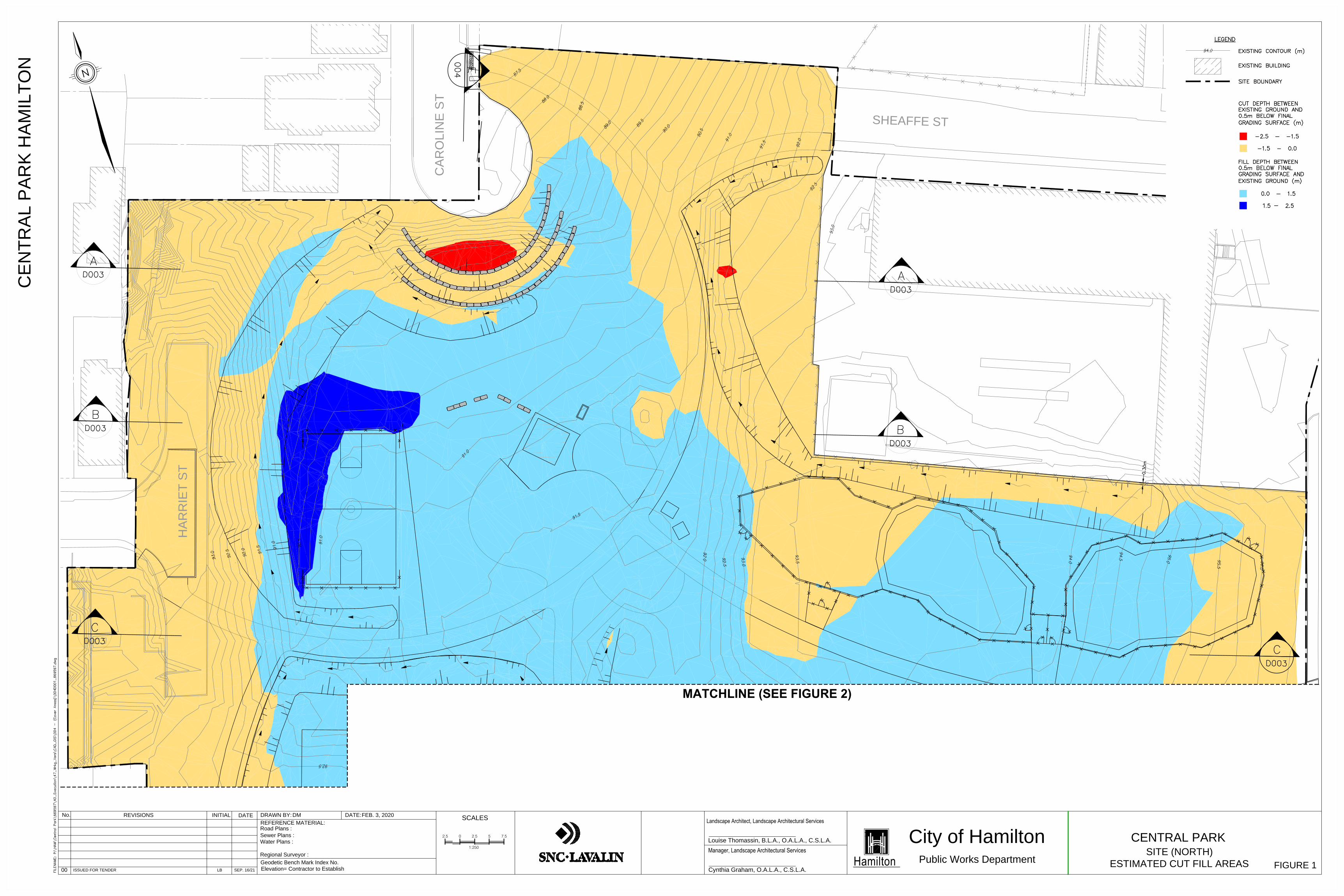
1 Central Park North – Approximate Cut and Fill Areas
2 Central Park South – Approximate Cut and Fill Areas
Appendices
A Risk Management Plan
B Surface Soil Human-Health Site Specific Target Levels and Ecological Site-Specific Target Levels

Soil Management Plan – City of Hamilton 1 669597 – September 15, 2021
1. Introduction This Soil Management Plan (SMP) provides guidance to the City of Hamilton for managing excavated materials generated during site redevelopment construction activities and future park land use of the property at 171 Bay St North, Hamilton, Ontario (the “site”) known as Central Park. Excavated materials may include soil, rock, construction debris (e.g. asphalt, concrete) and other wastes.
The SMP is an administrative control measure to mitigate or control exposure to contaminants of concern (COC) at the site, as required by the Risk Management Plan (RMP; SNC-Lavalin 2021) developed as part of a Human Health and Ecological Risk Assessment (HHERA) completed at the site (SNC-Lavalin 2019). The SMP is required because contact with contaminated soil at the site may result in unacceptable risk to human and ecological receptors. Implementing the SMP will reduce the likelihood of contact with contaminated soils. It shall be implemented at the site before barriers to contact with site soil (‘caps’) are constructed and after barrier construction when work on site may breach the cap and there is the potential for contact with soil below the cap. The SMP applies to construction as well as operation and use of the park and is to be implemented during any activities potentially resulting in contact with or exposing site soils.
The implementation of the SMP must be overseen by a Qualified Person (QP) as defined by O.Reg. 154.
2. Regulatory Requirements/ Standards/Guidelines
The following are the primary environmental regulatory drivers and technical guidance documents for excavated material and water management during the project:
› The Ontario Environmental Protection Act; › Ontario Regulation 347: General - Waste Management; › Ontario Regulation 153/04 - Records of Site Condition; › Ontario Regulation 406/19 – On-Site and Excess Soil Management; and Rules for Soil
Management and Excess Soil Quality Standards (MECP 2020, as amended).
Activities at the site must also comply with the risk management measures prescribed in the RMP prepared for the site (SNC-Lavalin 2020) included in Appendix A, as well as all other applicable provincial, municipal and federal legislation.
In addition to the above, relevant regulatory and institutional requirements should be considered in the contractor's emergency response plans, erosion and sediment control plans, transportation plans, and spill prevention plans.
3. Overview of Site Conditions Environmental site assessments and a HHERA were carried out by SNC-Lavalin to assess the soil, groundwater and soil vapour quality at the Site, in anticipation of planned redevelopment of the Site. The HHERA identified potential unacceptable risks to human and ecological health. COCs in soil and

Soil Management Plan – City of Hamilton 2 669597 – September 15, 2021
groundwater included benzene, toluene, ethylbenezene, and xylenes (BTEX), petroleum hydrocarbons (PHCs), polycyclic aromatic hydrocarbons (PAHs), and volatile organic compounds (VOCs). Buried wastes are also expected to be present at the site. The HHERA generated human-health site specific target levels (HH-SSTLs) and ecological site-specific target levels (E-SSTLs) for surface soil, presented in Appendix B. These soil target levels are concentration limits that have been determined to be protective of human and ecological receptors, and these values have been used to determine which soil is acceptable for reuse at the site and which soil must be remediated.
4. Health and Safety A Health and Safety Plan (HASP) is required where work is planned that will expose site soils, as required by the RMP developed for the site, in order to mitigate against unacceptable risk to workers. The HASP shall be prepared by a suitably qualified professional taking into account the nature and concentrations of the contaminants in the areas where work is planned. As implementation of the HASP will protect subsurface workers, subsurface site-specific target levels (SSTLs) are not considered further in this document.
The HASP shall include the following contaminant-specific protocols for workers conducting excavations at the site that may encounter soils and groundwater:
› The use of protective clothing that covers the arms and legs. Chemical resistant, disposable protective clothing should be used if there is a risk of contact with highly contaminated soil or groundwater. Contaminated or soiled clothing will be left on-site at the end of each workday. Clean, non-contaminated clothes will be worn each day;
› The use of work gloves for the handling of tools and equipment, and outer chemical resistant gloves for the direct handling of soils/groundwater;
› The use of safety eye-wear, including goggles or face shields if handling water/liquids; › Protocols for decontamination of equipment and personnel; › The use of suitable vapour meters to estimate organic vapour concentrations in trenches,
excavations, etc. and/or provide instruction to implement vapour mitigation through appropriate PPE (e.g. respirators) and/or ventilation of excavations;
› All workers will wash hands and faces before breaks and before leaving the work site; and › The results of the latest soil and groundwater analytical results must be listed in a schedule within
the HASP.
The HASP should also consider whether real-time monitoring and mitigation are required for naphthalene, benzene, and other volatile/odorous contaminants is required during construction. The HASP should be provided to the City at least two weeks in advance of commencement of site activities for review and approval.
5. Planning Prior to conducting excavation on the site or other works where there may be contact with site soils, results of previous investigations will be reviewed for information pertaining to soil and groundwater conditions that are likely to be encountered. A database should be maintained that includes, as a minimum, sampling location, sampling date, parameters submitted for analysis, analytical results and depth of sample.

Soil Management Plan – City of Hamilton 3 669597 – September 15, 2021
Construction site layout should consider stockpile locations, if required, before construction work begins and should be selected based on ability to control odour emissions, potential erosion and dust generation. Stockpile locations should be secured and fenced and ideally situated away from areas accessible to or frequented by the public and away from other sensitive areas. Site traffic, truck and vehicle routes, entrances, and exits to the site are to be identified and documented prior to initiation of construction work on-Site.
6. Excavated Material Management The following sections provide guidance on the management of excavated materials. This includes specific excavations to remediate environmentally or geotechnically poor quality soil, or general excavations for park redevelopment. Note that recommendations are presented based on the environmental quality of the excavated materials, not the geotechnical quality.
6.1. Erosion and Sediment Control A site-specific erosion and sediment control plan shall be developed by the Contractor to minimize erosion and sediment runoff during site works. The plan must meet applicable laws and regulations including soil management provisions from the Rules for Soil Management and Excess Soil Quality Standards (MECP 2020, as amended), OPSS 805 (Construction Specification for Temporary Erosion and Sediment Control Measures) and generally incorporate construction best practices.
The plan should include measures to minimize migration of contaminated soil including limiting areas of open excavations, covering and/or stabilizing excavated areas promptly, proper management of stockpiles (with tarping and lining as appropriate), runoff control using berms etc., management and approval of discharge to sanitary sewers or other approved treatment, and storm water control using silt fences and filter socks on catch-basins and utility covers as necessary.
When control measures are implemented, regular inspections must be completed and documented to ensure the measures are effective, with repairs completed promptly when required.
6.2. Dust Control Site activities such as clearing and grubbing, excavations, and stockpiling and hauling of materials may result in emissions of dust and other particulates if not properly controlled. The contractor shall develop a site-specific dust control plan to minimize the generation of dust during soil management activities. The plan must meet applicable laws and regulations including soil management provisions in the Rules for Soil Management and Excess Soil Quality Standards (MECP 2020, as amended), OPSS 506 (Construction Specification for Dust Suppressants) and incorporate construction best practices.
Measures to minimize the generation of dust include the application of water or other materials as appropriate to exposed soil and stockpiles, limiting duration of stockpiling activities, tarping of exposed soil/stockpiles to control dust as appropriate, reducing vehicle speeds for on-site vehicles, implementation of tire washing stations and restricting dust generating work in high wind conditions. Tracking of site soils onto public roadways is not permitted.
When control measures are implemented, regular inspections must be completed and documented to ensure the measures are effective, with repairs completed promptly when required.

Soil Management Plan – City of Hamilton 4 669597 – September 15, 2021
6.3. General Contamination Monitoring Procedures Soil quality at the site is poor. During excavation, the site must be monitored on a regular basis (daily) by the Contractors’ personnel and periodically the City’s representative. Visual and olfactory evidence should be used to monitor the presence of known or suspected contamination and/or wastes in all work areas, and specialized monitoring equipment may be required to assist with monitoring (e.g. photoionization detectors, combustible gas detectors).
Visual and olfactory evidence of contamination may include the following:
› Drums and containers; › Stained or discoloured earth in contrast with adjoining soil; › Fill material containing debris; › Trash/garbage or waste debris; › Suspected odours which emanate when the earth is disturbed (e.g. naphthalene is COC and has
an easily recognizable “mothball” odour); › Oily residue intermixed with earth; › Sheens, films or discolorations on groundwater; and, › Cinders/ash or other combustion by-products like ash.
Upon discovery of any previously unidentified or unanticipated soil contamination, the Contractor must immediately consult with the City's representative. As noted in Section 6.4, contaminated soil showing signs of high-level contamination, such as sheen, heavy staining and/or presence of wastes is not permitted for onsite reuse; it must be disposed offsite at a licenced facility.
6.4. On-Site Reuse of Soil During excavation, soil may be reused on site, subject to the following considerations:
› Segregation: Segregation is required of soil excavated from the surface (i.e. from ground surface to a depth of 1.5 m), soil that is excavated from the sub-surface (i.e. soil excavated from depths of 1.5 m and below) and soil that shows signs of contamination, such as sheen, heavy staining and/or the presence of waste materials. Surface and sub-surface soil shall be further segregated to allow identification of soil that has not yet been sampled, soil that has been sampled and results are pending, soil that is deemed suitable for reuse and soil that cannot be reused and must be disposed of off-site. The estimated locations of surface and sub-surface excavations across the site are presented in Figures 1 and 2.
› Sampling: Sampling is required to document soil quality prior to reuse/backfilling. Sampling of stockpiled excavated material shall be completed at the frequency identified in Table 2 (Minimum Stockpile Frequency) of Schedule E of O. Reg. 153/04. Each sample shall be analyzed for volatile organic compounds (VOC), petroleum hydrocarbons (PHC F1-F4), polycyclic aromatic hydrocarbons (PAH), polychlorinated biphenyls (PCBs), metals and hydride-forming metals, Sodium Adsorption Ratio (SAR) and Electrical Conductivity (EC). Results shall be compared to the Human-Health SSTLs (HH-SSTLs) and Ecological SSTLs (E-SSTLs) established for the site for surface soil. In the absence of a HH-SSTL or E-SSTL for a particular parameter, the Table 3: Full Depth Generic Site Condition Standards in a Non-Potable Groundwater Condition for residential/parkland/institutional property use and coarse textured soils shall be applied.

Soil Management Plan – City of Hamilton 5 669597 – September 15, 2021
Soil that meets both the HH-SSTLs and E-SSTLs established for surface soil (or the Table 3 standards referenced above, in the absence of a HH-SSTL) can be reused (backfilled) on site as cap, or under the cap at any depth.
Soil that does not meet the HH-SSTL, the E-SSTL established for surface soil, and/or the Table 3 site condition standards referenced above may be backfilled below the cap subject to the approval of the City’s Qualified Person, and must be evaluated on a case-by-case basis as the presence of volatile contaminants may require further consideration.
Note that there is an area of benzene-impacted soil in the south-central portion of the site that must be remediated and cannot be reused on site. For further information, refer to the attached RMP.
6.5. Off-Site Disposal of Soil and Excavated Waste If soil is generated onsite that cannot be reused, appropriate off-site disposal of this material must take place based on the waste characterization from the previous subsurface investigations, supplemented with additional testing, if required.
If solid wastes are encountered, including excavated building debris, concrete, asphalt, ash, wood, metal, glass, paper, cardboard, etc., it must be disposed off-site at a licensed disposal facility approved for the specific type of waste being disposed.
Based on the waste characterization completed during previous subsurface investigations (Englobe, 2018), an area of soil considered leachate toxic for lead (i.e. hazardous according to O. Reg. 347) was identified (Englobe borehole BH-19-17). Supplemental characterization of soil from this area is recommended to identify the extent of leachate toxic material and minimize the volume of soil required to be disposed of as hazardous waste. The City will be required to register the Site as a waste generator for the appropriate waste streams prior to the transportation and disposal of hazardous soil (and/or any liquid industrial waste hauled offsite). Waste manifests must be completed for subject wastes, and the waste haulers and receivers must have a Certificate of Approval / Environmental Compliance Approval applicable for the for the waste class being generated. Records of all waste haulers and receiver must be maintained by the Contractor.
Documentation (such as bills of lading, waste manifests, and analytical results supporting waste determination) is to be maintained for all soils, excavated solid waste and liquids removed from the site.
7. Imported Soil Sources of non-virgin soil to be imported to the site should be assessed and identified to the City prior commencing work. This assessment should include an evaluation of potentially contaminating activities and areas of potential environmental concern associated with the source site(s). This evaluation should consist of a site visit and a records review in accordance with of O. Reg. 406/19 to define the contaminants of concern associated with the source site. At a minimum, soil shall be analyzed for VOCs, PHC F1-F4, PAHs, PCBs, metals and hydride-forming metals, SAR and EC, pH, and any other contaminant of potential concern (COPC) identified at the generating site.
At least one soil sample shall be analyzed for each 200 m3 of non-virgin soil for the first 10,000 m3 of soil being brought to the site, and at least one soil sample shall be analyzed for each 450 m3 of soil being brought after the first 10,000 m3 from the same generating site. All material brought to the Site must be free of wastes, debris and all other forms of contamination.

Soil Management Plan – City of Hamilton 6 669597 – September 15, 2021
Regardless of the sampling frequencies identified above, the Contractor must warrant that imported soil meets the lower of the Table 3: Full Depth Generic Site Condition Standards in a Non-Potable Groundwater Condition for residential/parkland/institutional property use and coarse textured soils, or the HH-SSTLs and E-SSTLs developed for surface soil at the site. Confirmatory audit sampling will be completed by the City’s Representatives. Should imported material fail to meet acceptable criteria, the material shall be removed from the site and replaced with acceptable material at the Contractor’s cost.
Sources of virgin soil should be assessed and identified to the City prior to commencing work. The contractor must warrant that imported virgin soil meets the lower of Table 3: Full Depth Generic Site Condition Standards in a Non-Potable Groundwater Condition for residential/parkland/institutional property use and coarse textured soils, or the HH-SSTLs and E-SSTLs developed for surface soil at the site. Confirmatory audit sampling will be completed by the City’s Representatives. Should imported material fail to meet acceptable criteria, the material shall be removed from the site and replaced with acceptable material at the Contractor’s cost.
8. Groundwater Management If groundwater is encountered during excavation activities, it should be contained and managed in accordance with environmental requirements, including, but not limited to, characterization prior to disposal as required. The City’s Representative should provide input as to final method of discharge. Similarly, precipitation entering excavations should be collected and managed appropriately.
9. Record Keeping Written records will be maintained to document soil and groundwater management activities. At a minimum, record will be kept documenting:
› The dates and duration of excavation work on site › Weather and site conditions during excavation › Name of the Qualified Person overseeing the work › The location and depth of excavation, and onsite soil tracking › Results of all field screening and laboratory analytical results › Dust control measures implemented during the work › Contractors and/or haulers working on the site (including retaining weigh bill, bills of lading etc.) › Haulers and receiving sites for soil or contaminated groundwater removed from the site › Documentation such as bills of lading, waste manifests, and analytical results supporting waste
determination › Complaints received relating to site activities potentially coming into contact with site soils and
groundwater

Soil Management Plan – City of Hamilton 7 669597 – September 15, 2021
10. ClosurePrepared by:
Pravina Singh, M. Eng., P. Eng. Senior Environmental Engineer
Reviewed by:
Robert Timlin, P. Geo. Team Lead & Senior Environmental Project Manager
Environment & Geoscience Engineering, Design and Project Management
11. ReferencesEnglobe 2018. Geotechnical Investigation Report, Caroline Street North Reconstruction, Cannon Street
West to Barton Street West (Central Park), Hamilton, Ontario. February 27, 2018.
MOE, 2011. Soil, Ground Water and Sediment Standards for Use Under Part XV.1 of the Environmental Protection Act. April 15, 2011.
SNC-Lavalin, 2019. Human Health and Ecological Risk Assessment and Risk Management Plan, Central Park, 171 Bay Street North, Hamilton, Ontario. June 2019.
SNC-Lavalin, 2021. Risk Management Plan - Central Park, 171 Bay Street North, Hamilton, Ontario. September 2021.

Soil Management Plan – City of Hamilton 8 669597 – September 15, 2021

FIGURES
HAR
RIE
T ST
CAR
OLI
NE
ST
SHEAFFE ST
2.5 0 2.5 7.5
1:250
5
SCALES INITIAL DATEREVISIONSREFERENCE MATERIAL:
Geodetic Bench Mark Index No.Elevation= Contractor to Establish
DRAWN BY: DATE:
Regional Surveyor :
Road Plans :Sewer Plans :Water Plans :
No.
CEN
TRAL
PAR
K H
AMIL
TON
00 ISSUED FOR TENDER LB SEP. 16/21
DM FEB. 3, 2020
Hamilton
City of Hamilton CENTRAL PARK
Public Works Department
Landscape Architect, Landscape Architectural Services
Manager, Landscape Architectural ServicesLouise Thomassin, B.L.A., O.A.L.A., C.S.L.A.
Cynthia Graham, O.A.L.A., C.S.L.A. FIGURE 1
MATCHLINE (SEE FIGURE 2)
SITE (NORTH)ESTIMATED CUT FILL AREAS

MILL ST
RAI
LWAY
ST
CAR
OLI
NE
ST N
2.5 0 2.5 7.5
1:250
5
SCALES INITIAL DATEREVISIONSREFERENCE MATERIAL:
Geodetic Bench Mark Index No.Elevation= Contractor to Establish
DRAWN BY: DATE:
Regional Surveyor :
Road Plans :Sewer Plans :Water Plans :
No. DM FEB. 3, 2020
Hamilton
City of Hamilton CENTRAL PARK
Public Works Department
Landscape Architect, Landscape Architectural Services
Manager, Landscape Architectural ServicesLouise Thomassin, B.L.A., O.A.L.A., C.S.L.A.
Cynthia Graham, O.A.L.A., C.S.L.A.
MATCHLINE (SEE FIGURE 1)
SITE (SOUTH)ESTIMATED CUT FILL AREAS
CEN
TRAL
PAR
K H
AMIL
TON
FIGURE 200 ISSUED FOR TENDER LB SEP. 16/21

APPENDIX A Risk Management Plan

Risk Management Plan Central Park, 171 Bay Street North, Hamilton, Ontario City of Hamilton September 15, 2021 699597

Central Park, Risk Management Plan – The City of Hamilton ii
Notice to Reader This report has been prepared and the work referred to in this report has been undertaken by the Environment & Geoscience business unit of SNC-Lavalin Inc. (SNC-Lavalin) for the exclusive use of The City of Hamilton (the Client), who has been party to the development of the scope of work and understands its limitations. The methodology, findings, conclusions, and recommendations in this report are based solely upon the scope of work and subject to the time and budgetary considerations described in the proposal and/or contract pursuant to which this report was issued. Any use, reliance on, or decision made by a third party based on this report is the sole responsibility of such third party. SNC-Lavalin accepts no liability or responsibility for any damages that may be suffered or incurred by any third party as a result of the use of, reliance on, or any decision made based on this report.
The findings, conclusions, and recommendations in this report (i) have been developed in a manner consistent with the level of skill normally exercised by professionals currently practicing under similar conditions in the area, and (ii) reflect SNC-Lavalin’s best judgment based on information available at the time of preparation of this report. No other warranties, either expressed or implied, are made as to the professional services provided under the terms of our original contract and included in this report. The findings and conclusions contained in this report are valid only as of the date of this report and may be based, in part, upon information provided by others. If any of the information is inaccurate, new information is discovered, site conditions change, or applicable standards are amended, modifications to this report may be necessary. The results of this assessment should in no way be construed as a warranty that the subject site is free from any and all contamination.
Any soil and rock descriptions in this report and associated logs have been made with the intent of providing general information on the subsurface conditions of the site. This information should not be used as geotechnical data for any purpose unless specifically addressed in the text of this report. Groundwater conditions described in this report refer only to those observed at the location and time of observation noted in the report.
This report must be read as a whole, as sections taken out of context may be misleading. If discrepancies occur between the preliminary (draft) and final versions of this report, it is the final version that takes precedence. Nothing in this report is intended to constitute or provide a legal opinion.
The contents of this report are confidential and proprietary. Other than by the Client, copying or distribution of this report or use of or reliance on the information contained herein, in whole or in part, is not permitted without the express written permission of the Client and SNC-Lavalin.

Central Park, Risk Management Plan – The City of Hamilton iii
Executive Summary The Environment and Geoscience business unit of SNC-Lavalin was retained by the City of Hamilton (the City) to prepare an updated Risk Management Plan the property located at 171 Bay Street North, Central Park in Hamilton, Ontario (the “site”). Previous Environmental Site Assessment work, including Risk Assessment and supplemental Site assessment work was carried out by SNC-Lavalin to assess the soil, groundwater and soil vapour quality at the Site, in anticipation of planned redevelopment of the Site. The Risk Assessment identified potential unacceptable risks to human and ecological health.
Risk modelling and analysis presented in the Risk Assessment identified potential unacceptable risks to human and ecological health. The Risk Management Measures (RMMs) discussed are designed to mitigate potential unacceptable risks associated with the following exposure pathways, environmental media and contaminants:
› Park Visitor (public) › Surface Soil Direct Contact (ingestion and dermal contact) › Outdoor Air Inhalation from a Surface Soil Source
› Long-Term Outdoor Worker (e.g. landscape or maintenance worker) Surface Soil Direct Contact (ingestion and dermal contact)
› Subsurface Worker (e.g. landscape or maintenance worker) › Surface Soil Direct Contact (ingestion and dermal contact and inhalation of particulates) › Subsurface Soil Direct Contact (ingestion and dermal contact and inhalation of
particulates) › Trench Vapour Inhalation from a Surface Soil Source › Trench Vapour Inhalation from a Subsurface Soil Source › Incidental Direct Contact with Shallow Groundwater (ingestion and dermal contact)
› Off-Site Residents (e.g. neighbouring residential property) Indoor Air Inhalation of Volatile COCs from a Groundwater Source
› Off-Site Commercial Office Worker (e.g. neighbouring commercial property) › Indoor Air Inhalation from a Groundwater Source
› Ecological Receptors › Direct ecological contact with contaminated surface soil
The RMMs proposed herein have been developed to be protective of potential future park visitor receptors, off-site commercial and residential receptors, subsurface workers as well as ecological receptors. As a key assumption of the risk assessment was the application of a stratified soil approach, stratified soil conditions must be maintained.
Accordingly, the following RMMs are incorporated in this RMP:
› Carry out remedial excavation of surface soil with concentrations of benzene greater than 29.3 µg/g in the vicinity of BH-19-17 and complete verification sampling to mitigate outdoor inhalation risks;
› Install barrier to site soil (soil/fill cap or hard cap) across the entire property to mitigate direct contact with contaminated soil for park visitors, long term outdoor workers, and ecological receptors;

Central Park, Risk Management Plan – The City of Hamilton iv
› Implement a soil and groundwater management plan and health and safety plan to mitigate risks from exposure to groundwater, surface soil or subsurface soil, including trench vapour inhalation for subsurface workers.
› Implement an engineered groundwater migration mitigation system near portions of the northern property boundary to mitigate migration of contaminated groundwater that poses risks to off-site down-gradient residential and commercial receptors through inhalation of volatile COC in indoor air from a groundwater source.
› implementation of the soil management plan to restrict disturbance and relocation of impacted subsurface soil when excavation occurs and ensure stratified conditions are maintained at the RA Property).
The RMM listed herein are required to reduce exposure to COCs in soil, groundwater and vapour to levels at which no unacceptable risks are anticipated and/or to render the exposure pathways inoperable. The following details are included as it pertains to the RMMs described.
The localized remedial excavation at BH-19-17 is estimated to cover an area of approximately 18.5 m2 and extend to a depth of approximately 2 metre below ground surface (m bgs) to account for a volume of approximately 37 m3.
Site regrading to install the soft and hard fill caps is required. It is estimated that approximately 6,700 m3 of existing soil will need to be cut for accepting the fill cap. Assuming that a limited volume of soil would be reused at the site approximately 7,200 m3 of fill will be required to bring the surface to the required grade to accept the fill cap across the site. Approximately 13,600 m3 of material will be required for construction of the fill cap.
An engineered system should be implemented as an RMM to control groundwater movement at the property boundary and mitigate indoor air risks associated with migration of potentially impacted groundwater to off-site, down gradient residential and commercial properties.
The groundwater mitigation system should allow impacted groundwater to be treated in a manner that it would meet the Table 3 SCS at the property boundary. Suitable in-situ or ex-situ treatment alternatives may be implemented. The preliminary design of one alternative, a groundwater recovery trench is presented here. is.
The groundwater recovery trench will extend approximately 90 m along the northern property boundary, installed to approximately 12 m deep to intercept the deeper silty clay or clay layer and install a suitable infiltration drainage pipe, connected to two well risers and two “clean-out” ports. The trench will be separated from the surrounding site soil by a non-woven mesh geotextile and backfilled with clear stone. At surface the upper 0.5 m will consist of compacted fill material (forming part of the site fill cap) underlain by a 0.15 m thick sub-base of compacted granular material. Where the trench intersects existing Site utilities, an area equivalent to that of the utility trench plus 0.5 m on all sides will be backfilled with compacted clay or unshrinkable cement fill to prevent or minimize a preferential pathway connection between the utility trench and the groundwater recovery trench material. One extraction well riser will be constructed along the eastern extent of the trench and one well riser will be constructed west of the utility crossing.

Central Park, Risk Management Plan – The City of Hamilton v
Groundwater extraction volume calculation results indicate that the dewatering zone of influence is estimated to be approximately 11 m from the groundwater recovery trench. The typical daily water extraction volume is expected to be approximately 46,500 L. Although the expected daily water extraction volume, is estimated to be less than 50,000 L per day, the system may be classified as a pump and treat system and there may be periods where it exceeds 50,000 L/day, it is recommended that a factor of safety be applied to the typical daily extraction volume and permit to take water (PTTW) be obtained from the MECP on that basis.
Discharge from the groundwater recovery trench will be connected to the receiving sanitary line. If Hamilton Water requires pre-treatment, suitable treatment units which may consist of bag or carbon filters would also need to be incorporated. The system will be controlled by an electrical control panel connected to level switches within the pumping wells and over pressure safety monitors switches within the system. A secure, above ground structure to house this equipment is recommended and could be installed along the northern property line between Sheaffe Street and Caroline Street North. Based on the Site characterization studies, the contaminants of concern that may require treatment include sediment (for turbidity) and volatile organic compounds. PAHs were identified in the soil and groundwater at the site.
Future utility services shall be installed in trenches with aggregate and/or soil meeting the meeting the MECP Table 3 SCS to a minimum depth 500 mm below and 500 mm laterally from the limits of the services. Where a utility is to be installed in an area of heavy impact and potential free-phase contamination, additional mitigations are proposed to decrease risks of residual contamination impacting or migrating along the utility.
Administrative requirements included as part of the RMMs include the following provisions:
› Groundwater in or under the Property shall not be used as a source of potable water and no wells shall be installed on the RA Property for the purposes of obtaining potable water.
› A site specific health and safety plan should be developed and implemented during all intrusive, below-grade construction activities potentially coming in contact with or exposing site soil or groundwater.
› Following implementation of the cap, the health and safety plan is only required to be implemented when excavation will extend below the cap.
› Prior to site redevelopment, before any activities that have the potential to disturb soil are initiated, the site area shall be fenced off to secure the site from unauthorized access to prevent visitors/the public from contact with contamination.
› Any potential future growing of vegetation/plants for human consumption would require the plants to be grown in raised planting beds with imported clean potting soil and a separation textile installed at the base of the raised bed. Growing material should be sourced from commercial or otherwise approved suppliers. Soil sourced at the RA Property should not be used in raised beds.
› The fill cap or hard cap shall be maintained indefinitely. › The soil and groundwater management plans, health and safety plan and site fencing shall be
required for the RA Property during any activities potentially in contact with or exposing site soils and/or groundwater for as long as the COCs are present at the Property.
› The groundwater migration mitigation system shall be operated indefinitely or until it has been demonstrated that groundwater at the RA Property meets either the applicable generic SCSs or SSTLs.
› An inspection and maintenance program should be prepared and implemented to ensure the continuing integrity of the fill cap or hard cap as long as the COCs are present on the Site.

Central Park, Risk Management Plan – The City of Hamilton vi
› A monitoring and sampling program should be developed and implemented to monitor the effectiveness of the engineered groundwater migration mitigation system.

Central Park, Risk Management Plan – The City of Hamilton vii
Table of Contents NOTICE TO READER ......................................................................................................................... II EXECUTIVE SUMMARY .................................................................................................................... III TABLE OF CONTENTS..................................................................................................................... VII 1. INTRODUCTION AND BACKGROUND........................................................................................ 1 2. RISK MANAGEMENT PLAN ........................................................................................................ 1
2.1. RISKS IDENTIFIED BY RISK ASSESSMENT .................................................................................... 1 2.2. AREAS REQUIRING RISK MANAGEMENT MEASURES ..................................................................... 3
3. PROPOSED RISK MANAGEMENT MEASURES ......................................................................... 5 3.1. LOCALIZED REMEDIAL EXCAVATION IN THE VICINITY OF BH-19-17 .................................................. 6 3.2. BARRIER TO SITE SOILS ............................................................................................................ 6
3.2.1. Hard Cap ........................................................................................................................ 7 3.2.2. Soft (Fill) Cap .................................................................................................................. 7 3.2.3. Maintenance of Stratified Conditions ............................................................................... 9 3.2.4. Cut and Fill Volumes ....................................................................................................... 9 3.2.5. Imported Capping Material Soil Texture ......................................................................... 10
3.3. SOIL MANAGEMENT PLAN........................................................................................................ 10 3.4. GROUNDWATER MANAGEMENT PLAN ....................................................................................... 11 3.5. GROUNDWATER MIGRATION MITIGATION SYSTEM ...................................................................... 11
3.5.1. Groundwater Recovery Trench ...................................................................................... 11 3.5.2. Groundwater treatment and discharge ........................................................................... 13 3.5.3. Operation and Monitoring .............................................................................................. 14
3.6. UNDERGROUND UTILITY SERVICES AND TRENCH BLOCKS........................................................... 14 3.7. ADMINISTRATIVE CONTROLS.................................................................................................... 14
3.7.1. Prohibit Installation of Potable Wells .............................................................................. 14 3.7.2. Building Prohibition ....................................................................................................... 15 3.7.3. Health and Safety Requirements ................................................................................... 15 3.7.4. Site Fencing Requirements ........................................................................................... 15 3.7.5. Restrictions on Plants/Vegetation for Human Consumption ........................................... 16
4. DURATION OF RISK MANAGEMENT MEASURES ................................................................... 16 5. REQUIREMENTS FOR MONITORING AND MAINTENANCE .................................................... 16
5.1. BARRIER TO SITE SOILS .......................................................................................................... 16 5.2. GROUNDWATER MIGRATION MITIGATION SYSTEM ...................................................................... 17
6. CLOSURE .................................................................................................................................. 18 7. REFERENCES ........................................................................................................................... 19
Figures
1 Site Location Plan
2 Site Layout
3 Phase II Conceptual Site Model

Central Park, Risk Management Plan – The City of Hamilton viii
4 Summary of Surface Soil Results Exceeding HH-SSTLs
5 Summary of Subsurface Soil Results Exceeding HH-SSTLs (Subsurface Workers)
6 Summary of Groundwater Results Exceeding HH-SSTLs (Subsurface Workers)
7 Summary of Groundwater Results Exceeding HH-SSTLs (Off-Site Residential)
8 Summary of Groundwater Results Exceeding HH-SSTLs (Off-Site Commercial)
9 Proposed Extent of Localized Remedial Excavation
10 Schematic of Risk Management Measures
11 Areas Where Hard Cap and Soft (Fill) Cap Are Required
12 Proposed Groundwater Mitigation System Groundwater Monitoring and Sampling Network
Appendices
A Excerpt of the SSTL tables from the Risk Assessment report
Site Grading, Cut and Fill requirements and Soil Cap Distribution
B Groundwater Recovery Trench Design and Extraction Volume Calculation

Central Park, Risk Management Plan – The City of Hamilton 1
1. Introduction and Background The Environment and Geoscience business unit of SNC-Lavalin was retained by the City of Hamilton (the City) to prepare an updated Risk Management Plan the property located at 171 Bay Street North, Central Park in Hamilton, Ontario (the “site”) (Figures 1 and 2). Previous Environmental Site Assessment work (SNC-Lavalin, 2019a), including Risk Assessment (SNC-Lavalin, 2019b) and supplemental Site assessment work (SNC-Lavalin, 2020) was carried out by SNC-Lavalin to assess the soil, groundwater and soil vapour quality at the Site, in anticipation of planned redevelopment of the Site. The Risk Assessment identified potential unacceptable risks to human and ecological health.
A Risk Management Plan (RMP) was included with the 2019 Risk Assessment carried out by SNC-Lavalin, however, the RMP relied on assumptions about the extent of contaminants along the property boundaries and whether off-site soil vapour impacts may be occurring as a result of concentrations of contaminants in groundwater on the Site. Accordingly, a supplemental soil, soil vapour and groundwater investigation was completed by SNC-Lavalin in 2020. The supplemental investigation was completed to assess shallow soil quality in the vicinity of BH-19-17, update groundwater quality data on which proposed Risk Management Measure were based and assess soil vapour quality at the property boundary.
This updated RMP was completed in accordance with the SNC-Lavalin proposal dated June 26, 2019 to assess/delineate the area around BH-19-17 and assess the groundwater and soil vapour conditions to refine the design of the proposed Risk Management Measure (RMM).
2. Risk Management Plan 2.1. Risks Identified by Risk Assessment
Risk modelling and analysis presented in the Risk Assessment (SNC-Lavalin, 2019b) identified potential unacceptable risks to human and ecological health. The RMMs discussed in the following sections are designed to mitigate potential unacceptable risks associated with the following exposure pathways, environmental media and contaminants:
› Park Visitor (public) › Surface Soil Direct Contact (ingestion and dermal contact) – benzene, PHC F2-F3, PAHs
(acenaphthylene, benzo[a]anthracene, benzo[a]pyrene, benzo[b]fluoranthene, benzo[ghi]perylene, benzo[k]fluoranthene, chrysene, dibenz[a,h]anthracene, fluoranthene, indeno[1,2,3-cd]pyrene, 1- and 2-Methylnaphthalene, pyrene), metals (antimony, arsenic, cadmium, copper, lead, and zinc).
› Outdoor Air Inhalation from a Surface Soil Source – benzene.
› Long-Term Outdoor Worker (e.g. landscape or maintenance worker) › Surface Soil Direct Contact (ingestion and dermal contact) – benzene, PAHs
(acenaphthylene, benzo[a]anthracene, benzo[a]pyrene, benzo[b]fluoranthene, benzo[ghi]perylene, benzo[k]fluoranthene, chrysene, dibenz[a,h]anthracene, fluoranthene,

Central Park, Risk Management Plan – The City of Hamilton 2
indeno[1,2,3-cd]pyrene, and pyrene), metals (antimony, arsenic, cadmium, copper, lead, and zinc).
› Subsurface Worker (e.g. landscape or maintenance worker) › Surface Soil Direct Contact (ingestion and dermal contact and inhalation of particulates)
– PAHs (benzo[a]anthracene, benzo[a]pyrene, benzo[b]fluoranthene, benzo[k]fluoranthene, and dibenz[a,h]anthracene) and metals (antimony, arsenic, cadmium, copper, lead, and zinc)
› Subsurface Soil Direct Contact (ingestion and dermal contact and inhalation of particulates) – PAHs (benzo[a]anthracene, benzo[a]pyrene, benzo[b]fluoranthene, benzo[k]fluoranthene, dibenz[a,h]anthracene, fluoranthene, indeno[1,2,3-cd]pyrene, and 1-2-methylnaphthalene), metals (arsenic and lead)
› Trench Vapour Inhalation from a Surface Soil Source – benzene, toluene, xylenes, PHC F1 and F2, styrene, PAHs (acenaphthylene, naphthalene) and mercury
› Trench Vapour Inhalation from a Subsurface Soil Source – benzene, ethylbenzene, xylenes, PHC F1 and F2, trichloroethylene, vinyl chloride, naphthalene, and mercury
› Incidental Direct Contact with Shallow Groundwater (ingestion and dermal contact) – Benzene, PHC F2 and F3, PAHs (acenaphthene, acenaphthylene, benzo[a]pyrene, benzo[b]fluoranthene, benzo[k]fluoranthene, indeno[1,2,3-cd]pyrene, naphthalene)
› Off-Site Residents (e.g. neighbouring residential property) › Indoor Air Inhalation of Volatile COCs from a Groundwater Source – benzene, toluene,
ethylbenzene, xylenes, PHC F1 and F2, styrene, trichloroethylene, and vinyl chloride, PAHs (acenaphthene, acenaphthylene, fluorene, and naphthalene), and mercury
› Off-Site Commercial Office Worker (e.g. neighbouring commercial property) › Indoor Air Inhalation from a Groundwater Source – benzene
› Ecological Receptors
› Direct ecological contact with contaminated surface soil – cyanide EC, SAR, antimony, arsenic, HWS boron, cadmium, copper, lead, zinc, benzene, xylenes, styrene, PHC F1-F4, and PAHs
The described risks are depicted in a conceptual site model in Figure 3.
It is noted that although indoor air inhalation of volatile COCs from a groundwater source indicates potential risk from several PAHs, however, only naphthalene of which was included in the soil vapour sampling program. This is considered appropriate since naphthalene is the only PAH that has a health-base indoor air criteria listed in Appendix IV in MECP Soil Vapour intrusion Assessment Guidance (MOE, 2013), for the evaluation of indoor air contamination resulting from subsurface vapour intrusion at brownfields sites. As such, it was determined that naphthalene can be used as a surrogate for the evaluation of indoor air inhalation risk of PAHs.
Additionally, for mercury, the compound was carried in the RA as a result of a single elevated RDL for one soil sample and there have been no detectable concentrations of mercury in groundwater at the Site, as such it is not considered a contaminant of concern. Further rationale is provided to rule out risk associated with mercury in that, although elemental mercury is volatile, almost all soil mercury is not elemental, therefore, mercury is assumed to be non-volatile in the absence of evidence of an elemental mercury release.

Central Park, Risk Management Plan – The City of Hamilton 3
The RMMs proposed herein have been developed to be protective of potential future park visitor receptors, off-site commercial and residential receptors, subsurface workers as well as ecological receptors. As a key assumption of the risk assessment was the application of a stratified soil approach, stratified soil conditions must be maintained.
2.2. Areas Requiring Risk Management Measures
RMMs are required in areas where soil and/or groundwater quality exceeds the applicable site specific target levels (SSTLs).
Surface Soil
Surface soil impacts posing risks are prevalent across the majority of the RA Property. Historically, the site has been subject to extensive infilling and there is heterogenous fill material though out the site. Due to the heterogeneous nature of subsurface conditions, detailed delineation of impacts was not feasible and instead assessment activities were developed to investigate areas with the expected maximum concentrations of contaminants of concern for the purpose of assessing risk. Figure 4 indicates locations where surface soil sample concentrations were greater than the HH-SSTLs protective of Park Visitors, Long-Term Outdoor Workers, Off-Site Residents, and Off-Site Commercial Workers evaluated in the HHRA.
The need for a RMM to address surface soil risks is primarily driven by the human health risks (e.g. surface soil concentrations exceeding the HH-SSTLs). There was only one sampling location (BH-01-17) where the shallow soil conditions met the HH-SSTLs but exceeded an E-SSTL based on an elevated sodium adsorption ratio (SAR) value. At all other surface soil locations where ecological risks are present, human health risks are also present. As such, where a RMM will be applied to address the human health risk in surface soil, it will also address the ecological risk.
Outdoor Inhalation (Soil)
The outdoor inhalation risk to Park Visitors from benzene exposure in shallow soil is calculated from a single sampling location (SS-2 at BH-19-17 at 0.8 to 1.4 m bgs) with a benzene concentration that is significantly higher (141 μg/g) than concentrations for both surface and subsurface soil in the remainder of the RA Property (ranging from <0.0068 μg/g to 2.7 μg/g in surface soil and <0.0068 μg/g to 27.5 μg/g in subsurface soil). Subsequent soil sampling during November 2019 revealed that soil in the vicinity of BH-19-17 meets the Table 5 Surface soil standards as well as the HH-SSTL, accordingly the RMM proposed below includes that this localized area be remediated, and verification sampling be carried out during park redevelopment.
Figure 5 indicates all locations where subsurface soil sample concentrations were greater than the HH-SSTLs protective of subsurface workers. Subsurface soil impacts posing risks to subsurface workers are prevalent over the majority of the RA Property. Due to the heterogenous nature of the fill, it was considered unlikely that the limits of contamination could be reasonably determined, and surface soil impacts posing unacceptable risk to subsurface workers are interpreted to extend across the majority of the RA Property. The RMMs discussed below to address risks to trench workers from surface and subsurface soil will therefore apply across the whole site area.

Central Park, Risk Management Plan – The City of Hamilton 4
Direct Contact (Groundwater)
A summary of groundwater impacts posing risks to subsurface workers is presented in Figure 6. Impacted groundwater posing risks is located in the north central portion of the RA Property and at an isolated area in the eastern portion of the RA Property (MW-101). Significant trench work will be associated with the site re-development as the City is planning to replace the existing sewers and water main which run through the RA Property from north to south (south of Caroline Street North) and east-west connecting to Harriet Street, Mill Street and Railway Street. The RMMs discussed below to address groundwater risks to subsurface workers will apply throughout the site where contact with groundwater is present, and is expected to be most prevalent in the northern section of the RA Property adjacent to the benzene/PHC/PAH groundwater impacts in shallow groundwater in that area.
Inhalation of Vapours (Soil and/or Groundwater)
The risk assessment identified potentially unacceptable risks associated with the inhalation of indoor air at off-site residential or commercial properties or on-site utility trench excavation areas impacted by volatile contaminants sourced from contaminated soil and/or groundwater, at locations were HH-SSTLs, protective of Inhalation of Indoor Air, were exceeded. The areas where groundwater concentrations exceed the HH-SSTLs protective of Inhalation of Indoor Air at off-site residential and commercial properties are shown in Figure 7 and Figure 8, respectively. No enclosed buildings designed to be occupied will be constructed on site.
There are groundwater impacts in the north central portion of the RA Property, with several volatile parameters presenting potentially unacceptable risk to down gradient, off site residential areas north of the RA Property (along Caroline Street North) and a second area with groundwater impacts in the west central portion of the RA Property which was based primarily on chlorinated solvent impacts (namely TCE) presenting potential elevated risk to the off-site cross-gradient residential area west of the RA Property (north of Harriet Street).
This potential risk was further evaluated through a more direct line of evidence, through the evaluation of soil vapour samples. Soil vapour analytical results were compared to health based indoor air criteria, adjusted by attenuation factors for residential or commercial land uses, as appropriate depending on the adjacent land use.
At the time the RA was completed, one round of soil vapour sampling had been completed, and it was conservatively inferred that vapour mitigation risk management measures may be required along several property boundaries. To refine the required risk management measures additional soil vapour data was collected in 2018, and with an expanded soil vapour probe network in 2019 and 2020 (SNC-Lavalin, 2020). The results of the additional assessment indicated that increased vapour risk to residential receptors was detected at only one location SVP18-04 (situated away from the property boundary), with vapour samples from soil vapour probes installed closer to the property limits/off-site receptors meeting the adjusted health based indoor air criteria . No increased risk to commercial receptors was identified. Consequently, the only risk management measure required to mitigate unacceptable risk to off-site receptors comprises mitigating the migration of groundwater from the area of the site where an unacceptable vapour risk was identified.
The groundwater migration mitigation risk management measure will not mitigate potential risks associated with contamination that may have already migrated from the site, however, as noted above,

Central Park, Risk Management Plan – The City of Hamilton 5
soil vapour sampling completed at the north property limit (SVP19-03 and SVP18-01) did not identify an unacceptable risk at the property limit.
3. Proposed Risk Management Measures
The following sections presents the proposed RMMs to mitigate the risks identified above.
To mitigate off-site groundwater migration and inhalation of indoor air impacts off-site to the north, a groundwater migration mitigation system can be designed to extend along the northern property boundary (SNC-Lavalin, 2020). The areas where groundwater concentrations exceed the HH-SSTLs protective of Inhalation of Indoor Air for off-site commercial properties are shown in Figure 8. Groundwater impacts are present in the north central portion of the RA Property with benzene concentrations presenting risk to the down gradient off site commercial property north of the RA Property (along Caroline Street North).
Based on the current soil, groundwater and soil vapour data (SNC-Lavalin 2019a and 2020), RMMs will be required to address risks to the down-gradient residential and commercial receptors to the north (along Caroline Street North).
Accordingly, the following RMMs are incorporated in this RMP:
› Carry out remedial excavation of surface soil with concentrations of benzene greater than 29.3 µg/g in the vicinity of BH-19-17 and complete verification sampling to mitigate outdoor inhalation risks;
› Install barrier to site soil (soil/fill cap or hard cap) across the entire property to mitigate direct contact with contaminated soil for park visitors, long term outdoor workers, and ecological receptors;
› Implement a soil and groundwater management plan and health and safety plan to mitigate risks from exposure to groundwater, surface soil or subsurface soil, including trench vapour inhalation for subsurface workers.
› Implement an engineered groundwater migration mitigation system near portions of the northern property boundary to mitigate migration of contaminated groundwater that poses risks to off-site down-gradient residential and commercial receptors through inhalation of volatile COC in indoor air from a groundwater source.
› implementation of the soil management plan to restrict disturbance and relocation of impacted subsurface soil when excavation occurs and ensure stratified conditions are maintained at the RA Property).
The scope of the planned re-development of the RA Property includes utility replacement/construction and as such, trench blocks are to be installed during construction work as an additional risk management measure to mitigate the potential for utility trenches to serve as preferential migration pathways for soil vapours and groundwater.
Given the assumptions and receptors considered in the RA, administrative controls also apply to the RA Property and are described further in Section 3.5. These include restrictions for groundwater use, buildings and growing of plants/vegetation for human consumption, as well as requirements for fencing during re-development work.

Central Park, Risk Management Plan – The City of Hamilton 6
The RMM listed herein are required to reduce exposure to COCs in soil, groundwater and vapour to levels at which no unacceptable risks are anticipated and/or to render the exposure pathways inoperable.
3.1. Localized remedial excavation in the vicinity of BH-19-17 Based on the findings of the 2018 Phase II ESA (SNC-Lavalin, 2019a) and the supplemental investigation completed in 2020 (SNC-Lavalin, 2020) it is required to carry out remedial excavation in the immediate vicinity of BH-19-17. It is proposed that excavation extents be bounded by test pit locations TP19-02, TP19-03, TP19-04 and TP19-05. Delineation of the benzene exceedance is incomplete at the eastern extent. Accordingly, it is required that verification sampling be carried out at the excavation extents to ensure remaining site surface soil meet the HH-SSTL for benzene at this location. Should verification samples not meet the required HH-SSTL, it is required that the excavation be extended until concentrations of benzene in confirmation soil samples analysed from the floors and walls of the completed excavation are less than the HH-SSTL.
The estimated extent of benzene impacted soil at BH-19-17 is shown in Figure 9 The estimated volume for excavation is as follows:
Location Area (m2) Thickness (m) Volume (m3)
BH-19-17 18.5 2 37
Verification samples should be collected at a frequency equal to or greater than that described in Schedule E, Table 3 of (Minimum Confirmation Sampling Requirements for Excavation) in O. Reg 153/04.
Following excavation, where benzene concentrations meet the HH-SSTL the excavation can be backfilled with imported clean fill which meets applicable HH-SSTL or Table 5 surface soil standards, and finished with a 0.5 m fill cap. As described in Section 2.1, stratified soil conditions must be maintained at the site and 1.5 m of soil must be maintained over the subsurface soil.
Finally, any excavated surface soils in this area which have been confirmed by testing to meet the HH-SSTL but exceed Table 5 surface soil standards, may only be reused on-site provided they are overlain a minimum of 1.5 m clean material and fill cap.
The remedial excavation shall be supervised by a Qualified Person (as defined by O. Reg. 153/04) and the results of the excavation program documented in a report.
3.2. Barrier to Site Soils As the future use of the site is parkland use, a barrier is required to mitigate human and ecological receptors coming into direct contact with site soils. The barrier can be comprised of a hard cap or soft (fill) cap, to be compatible with the park design and should be implemented in conjunction with park redevelopment. The cap design has been revised since the Risk Assessment, based on additional consideration of the protection provided by the barriers. As described in the Section 2.2, the cap is required across the whole site (Figure 4).
Inspection and maintenance are required to ensure the integrity of the cap is maintained. Details of the required inspection and maintenance program are described in Section 5.1.

Central Park, Risk Management Plan – The City of Hamilton 7
The minimum requirements to establish a barrier to site soils as outlined below (and illustrated in Figure 10) are intended to mitigate direct contact exposure risk to humans (excluding subsurface workers whose exposure is managed through health and safety planning) and ecological receptors. Consideration in the design was given to the requirements of the MGRA model risk management approach (MOECC, 2016a) as well as alternate capping approaches from other jurisdictions described in the RA (Section 5.4.2.2 of SNC-Lavalin, 2019b).
Areas where a hard cap or soft (fill) cap will be installed are illustrated on Figure 11. Figures documenting the installation of the cap should be prepared at the conclusion of the redevelopment program.
3.2.1. Hard Cap In areas of the site where the park design calls for ‘hardscape’ (e.g. paved areas, concrete surfaced play areas such as basket ball courts, walkways consisting of asphalt, etc.), the barrier to site soils shall consist of a layer of clean fill above the impacted site soils consisting of a minimum thickness of 0.15 m of compacted granular or sub-base material, as appropriate, followed by a minimum thickness of 0.075 m (75 mm) of concrete, asphalt or acceptable hard, cured-in-place, surface finish at grade. A suitable geotextile marker layer shall be placed between the subsoil and the base of the hard cap.
A schematic design of a typical hard cap cross-section is presented on Figure 10.
3.2.2. Soft (Fill) Cap In areas of the site that will be ‘soft scaped’ (e.g. play areas and grassed and landscaped areas) a soft or fill cap shall be installed. The soft cap will typically be composed suitable surface finishes (e.g. soft or rubberized playground floor, grass sod, engineered wood fiber and/or decomposed granite as appropriate) followed by a layer of soil and a marker layer. The soil layer will:
› Provide a barrier and isolate contaminated soil from direct contact by site receptors; and, › Facilitate growth of vegetation at the site to improve aesthetics and minimize erosion.
It is required that a geotextile marker layer be installed across areas that will require mitigation against animal burrowing or to limit rooting of trees and shrubs (e.g. areas landscaped with trees and/or shrubs, dog park areas) into contaminated soil.
In vegetated areas where deep rooted plants are not planned to be present, considering that a 50 cm soil cap is anticipated to provide adequate plant community protection from contaminated soil, the geotextile primary purpose is as a visual indicator to demarcate contaminated soil from clean soil. The geotextile is not needed to provide a physical barrier to root penetration, therefore a number of permeable material options are available including geogrids.
Accordingly, across the majority of the redeveloped park (e.g. grassed or sports fields), where geotextile will not be required, the Soft (fill) cap will be completed with a suitable alternative, e.g. a geogrid, to serve as a warning indicator to individuals excavating on the property and to individuals performing cap integrity observations.
Schematic designs of a typical soft (fill) cap cross-section with geotextile and a soft (fill) cap with geogrid are presented on Figure 10.

Central Park, Risk Management Plan – The City of Hamilton 8
Based on the redevelopment plan for the Site the areas where a soft (fill) cap with geotextile, a soft (fill) cap with geogrid, and a hard cap is required are presented in Figure 11.
3.2.2.1. Soft (fill) cap specifications The thickness of the soft (fill) cap layer is to be at least 0.5 m and composed of a vegetated topsoil layer and a clean soil layer which meets the soil quality standards for the site MECP Table 3 SCS for coarse textured soil in residential/parkland land use setting). The rationale for the thickness of the soft (fill) cap layer is provided below.
The cap serves to make the human direct contact exposure route inoperable by preventing contact with contaminated soils during normal activities conducted by park visitors and long-term maintenance workers. Considering that these activities do not cause significant soil disturbance under normal site use, conceptually, only a nominal thickness of soil is required to render this pathway inoperable. However, applying a 0.5 m soil cap allows for a factor of safety for minor disturbance of surface soil without exposing human receptors to contaminated soil. By incorporating an isolation layer (geotextile) or visual marker layer, a significant decrease in cap thickness and potential exposure of contaminated soil would be readily apparent and corrective action (cap repair) can be implemented.
The thickness of the soft (fill) cap layer to mitigate ecological risks is based on the following considerations:
› The representative depth where exposure to plants and soil invertebrates may occur is the top 30 cm (based on the recommended sampling depth relevant to exposure in Suter, 2007);
› A US EPA (2015) meta-analysis study identified the soil zone of highest biological activity for soil-dwelling ecological receptors based on invertebrate density, microbial biomass and density, root biomass and root production to be 25 to 30 cm and low and essentially no difference in activity at depths greater than 50 cm. The study evaluated both grassland and forest environment types;
› The natural root distribution of most trees is present within the top 40 cm of soil (Watson and Himelick, 1992);
› In temperate grasslands, forests and crop lands, the majority of root biomass is in the upper 30 cm of the soil (52-83%, Jackson et al, 1996). An updated analysis using the same data and new data by Schenk and Jackson (2002) identified a 95th percentile meadow root depth of 40 cm and a 95th percentile cool temperate forest root depth 104 cm; and
› The MECP MGRA includes a ‘Hard Cap or Fill Cap Barrier (1.0 m specified greater thickness) risk management measure’ for all property uses, however, no rationale is provided for this thickness, accordingly it is inferred that there is no reason to believe a 0.5 m cap will not make the human direct contact route inoperable. Further, this barrier (specified in the MGRA) does not require the inclusion of a marker layer, whereas the barrier proposed for the site will serve as visual indicator of an area requiring repair.
› The frequency of cap inspection may be adjusted to be more frequent during higher park use periods and following high rainfall or seasonal events. Further, regulatory agencies recommend or have accepted cap thicknesses of less than 1 m as follows:
o The German Soil Protection Ordinance (BBODSCHV, 1999 in Meuser, 2013) provides recommended minimum thicknesses of clean soil caps intended to exclude human direct contact risks. These are 35 cm in playgrounds (with a geotextile barrier below the soil cap) and 10 to 35 cm in vegetated parks which do not experience digging activities;

Central Park, Risk Management Plan – The City of Hamilton 9
o A 60 cm to 90 cm (2 to 3 foot) cap is typically considered acceptable in the US for non-residential contaminated areas (US EPA, 2010). The rationale for this depth does not seem to be readily available; and
o The Ontario Ministry of Environment, Conservation and Parks has accepted use of 50 cm soft caps at contaminated sites (for example CPU 0371-8TYQMY, for parkland use), which is shallower than RSC based requirements, with the incorporation of a geotextile in the cap design (consistent with the cap design detailed for the Site).
Based on these regulatory agencies’ approach, it can be inferred that, in the absence of ground disturbance, or with the addition of a physical layer such as a geotextile, a soil cap of as little as 10 cm in thickness serves to disrupt the receptor pathway.
For consideration of ecological receptors, a soil cap depth in excess of 30 cm and up to approximately 40 cm may be considered suitable to maintain invertebrate communities and shallow rooted plant species and a cap thickness greater than approximately 50 cm may provide little additional benefit in terms of mitigating direct contact exposure based on US EPA (2015) data.
The selection of a soil cap thickness though needs to consider both necessary root depth requirements to allow for proper plant health and support and moisture storage requirements when a geotextile is part of the cap design. A 50 cm soil cap with geotextile barrier is potentially not suitable for areas with deep rooted plant species such as many trees and some shrubs where insufficient support may leave trees vulnerable to blow-over and cap depth may provide insufficient moisture storage (since deeper rooting is restricted by the recommended geotextile) to maintain tree and shrub plant health in the summer.
As a result, a 50 cm soil cap is recommended for the site and in areas where deep rooting plants are planted, their root balls must be placed in an excavation and surrounded on all sides by a soil layer no less than 0.5 m thick, MECP Table 3 SCS for coarse textured soil in residential/parkland land use setting.
3.2.3. Maintenance of Stratified Conditions Where the re-development design does not allow a grade adjustment of +0.5 m, a grade lowering would first be required to accommodate a fill cap, or accept a hard cap as required. If the existing grade is to be lowered before the cap is installed, the thickness of the cap must be proportionally increased from the minimum of 0.5 m by an amount equal to the lowering of the initial grade, to a maximum of imported fill thickness of 1.5 m in order to maintain the stratified soil conditions assessed in the Risk Assessment. Excavated surface soils may be reused on-site provided they are also capped by the minimum 0.5 m fill cap or hard cap in accordance with the soil management plan for the RA Property.
3.2.4. Cut and Fill Volumes Based on the existing grade plan, as surveyed (received from the City of Hamilton) and the proposed final grade based on the park redevelopment plan, the following cut and fill requirements are estimated as indicated in Appendix A.
As stratified site condition standards need to be maintained, any potential reuse of excavated material at the site should be cognizant of the final elevation of its final placement and should not be less than 1.5m bgs (final grade). It is estimated that approximately 6,700 m3 of existing soil will need to be cut for accepting the fill cap. Assuming that a limited volume of soil would be reused at the site approximately 7,200 m3 of fill will be required to bring the surface to the required grade to accept the fill cap across the site. Approximately 13,600 m3 of material will be required for construction of the fill cap. Any imported

Central Park, Risk Management Plan – The City of Hamilton 10
material to be used for capping purposes shall be either crusher run aggregate (e.g. Granular A or B) or soil material otherwise certified to meet the SSTLs or Table 3 Standards for parkland use. The SSTLs are specified in the Risk Assessment and an excerpt of the SSTL tables from the Risk Assessment report (SNC-Lavalin 2019b) are included in Appendix A.
3.2.5. Imported Capping Material Soil Texture It is understood that the City wishes to reuse soil from a current stockpile present at the Site to supplement fill requirements at the Site. Some or all of this stockpile may be used during installation of utilities at the Site, remaining soil may be used for capping material.
Soil grain size distribution samples were collected of the soil stockpile designated to be used as capping material. The soil was brought from nearby Churchill Park in west Hamilton. Based on the results of the grain size distribution by sieve and hydrometer, the soil samples can be classified as fine textured with between 92 to 96% of particles, by mass, smaller than 0.075 mm in diameter, and corresponds to soil type of clay and silty clay.
The fine textured material affects the soil’s infiltration rate, which determines how much and how quickly precipitation can be taken in by the soil. If the rate of precipitation exceeds the infiltration rate, ponding and surface runoff may occur. Where topographic gradient permits runoff without causing erosion, a higher clay content may be acceptable. However, in locations where very low topographic gradient is present, e.g. in the vicinity of the sports field, it is desirable to achieve infiltration suitable to avoid surface ponding and runoff.
Soil texture of the capping material should consist of suitably graded material, typically with a clay percentage less than 30%, which will allow appropriate drainage and infiltration of precipitation and limit formation of puddles. It is desirable to have a surface infiltration of 9 to 15 mm/hr, similar to that of silt loam. The final infiltration rate and required soil texture should be assessed by a landscape architect and incorporated in the park design.
3.3. Soil Management Plan A soil management plan (SMP) should be implemented during any activities which may potentially come in contact with or expose site soils. The SMP will be implemented to minimize exposure to COCs and to ensure that soil placed on the RA Property (re-used or imported) meets appropriate stratified SCSs or SSTLs. This plan shall be developed by and overseen by a Qualified Person as described under O. Reg. 153/04 and include, but not be limited to, the following components:
› Dust control measures and prevention of soils tracking by vehicles and personnel from the Site, including wetting of soil with potable water, reduced speeds for on-Site vehicles, tire washing stations and restricting work in high wind conditions.
› Management of excavated materials to minimize exposure to and migration of contaminated soil, including cleaning equipment, placement of materials for stockpiling on designated areas lined and covered with polyethylene sheeting, bermed and fenced to prevent access, runoff control to minimize contact and provisions for discharge to sanitary sewers or other approved treatment.
› The development and implementation of protocols for assessing soil excavated at, brought to or removed from the RA Property.
› Protocols and procedures to ensure the placement of excavated or imported soil meets the appropriate depth-specific standards.

Central Park, Risk Management Plan – The City of Hamilton 11
› Storm water management measures to control the potential transport of COCs off-Site during on-Site construction/redevelopment activities. This shall include, but to not be limited to, silt fences and filter socks on catch-basins and utility covers as necessary.
› Characterization of excavated materials requiring off-site disposal, such that disposal as a waste will be in accordance with the provisions of O. Reg. 347, as amended, made under the Act.
› Record keeping including, but not to limited to, dates and duration of work, weather and Site conditions, location and depth of excavation and soil placement activities, dust control measures, stockpile management and drainage, all soil and groundwater characterization results, names of the Qualified Persons, contractors, haulers and receiving Sites for any excavated soils/materials or contaminated groundwater removed from the property and any complaints received relating to Site activities.
3.4. Groundwater Management Plan A groundwater management plan should be developed and implemented to describe management handling and disposal requirements for groundwater encountered during excavation associated with re-development work (notably utility upgrades/replacements) or implementation/installation of any RMMs (e.g. the engineered groundwater mitigation system).
Based on details of the proposed work, an evaluation should be completed to determine if a Permit to Take Water may be required to handle the volumes of groundwater expected within the excavations. During rain events, run-off and rainfall should also be diverted away from any open excavations. Record keeping for groundwater management can be done in coordination with the SMP’s record keeping requirements listed in Section 3.3.
3.5. Groundwater Migration Mitigation System An engineered system should be implemented as an RMM to control groundwater movement at the property boundary and mitigate indoor air risks associated with migration of potentially impacted groundwater to off-site, down gradient residential and commercial properties.
The groundwater mitigation system should allow impacted groundwater to be treated in a manner that it would meet the Table 3 SCS at the property boundary. Suitable in-situ or ex-situ treatment alternatives may be considered. The preliminary design of one alternative, a groundwater recovery trench, is presented here as . The location of the groundwater mitigation system at the northern property boundary allows for connection of discharge to the sanitary sewer alignment along Sheaffe street. It is anticipated that Hamilton Sewer Use Bylaw requirements may necessitate treatment of the collected groundwater prior to discharge. As this is a City collection system discharging to a City receiver, obtaining input and clarification on pre-treatment expectations from the Hamilton Water Division of the City’s Public Works Department is recommended.
3.5.1. Groundwater Recovery Trench Based on the findings of the preceding work including the Phase II ESA and supplemental subsurface investigations, sufficient data were collected to prepare a design for the proposed groundwater recovery trench. The design of the groundwater recovery trench is documented in Appendix B.
It is proposed to construct a groundwater recovery trench aligned perpendicular to the direction of groundwater flow, down gradient of the area where maximum concentrations of contaminants of concern

Central Park, Risk Management Plan – The City of Hamilton 12
have been detected in groundwater, extending the full depth of the upper fill layers in the vicinity of the northern property boundary. It is proposed to advance a trench to approximately 12 m deep to intercept the deeper silty clay or clay layer and install a suitable infiltration drainage pipe, connected to two well risers and two “clean-out” ports. The trench will be separated from the surrounding site soil by a non-woven mesh geotextile and backfilled with clear stone. At surface the upper 0.5 m will consist of compacted fill material (forming part of the site fill cap) underlain by a 0.15 m thick sub-base of compacted granular material. Drawings depicting the trench design are provided in Appendix B, with a discussion of the design provided below.
Where the trench intersects existing Site utilities, an area equivalent to that of the utility trench plus 0.5 m on all sides will be backfilled with compacted clay or unshrinkable cement fill to prevent or minimize a preferential pathway connection between the utility trench and the groundwater recovery trench material. If required, steel separating plates can be installed to separate the trench-block low permeability backfill from the clear stone backfill.
One extraction well riser will be constructed along the eastern extent of the trench and one well riser will be constructed west of the utility crossing.
For the purpose of calculating the groundwater extraction volume, the following assumptions were made based on the available information:
› The open cut method (with a temporary shoring system) will be used to facilitate the construction/installation of the trench (i.e., excavation walls will be approximately vertical).;
› The target groundwater level is approximately 5 m from the bottom of the trench;
› The base of the water bearing zone is assumed to be at the bottom of the trench excavation.;
› The majority of the groundwater drawdown will occur within the sand, silty sand fill; and
› The water bearing zone is considered to be unconfined.
The target groundwater level may be adjusted based on the observations of the groundwater monitoring program following commissioning of the system and the observed gradients north of the trench. A gradient towards the south is required to be achieved between the northern property boundary and the trench.
Input parameters for dewatering evaluation are summarized in Table 4.1.
Table 4.1: Input Parameters for Trench Dewatering Evaluation Parameters Groundwater Recovery Trench
Length and width of excavation (m) Approximately 90 m long by approximately 2 m
wide
Bottom of excavation (mbgs) Ranging from 10 to 12 (approximately 78 m asl to 81 m asl)
Initial groundwater level (mbgs) 1.9 (approximately 87 m asl) Target groundwater level (mbgs) 4.9 (approximately 84.5 m asl) Groundwater drawdown (m) 3
Hydraulic conductivity (m/s) 1.1 x 10⁻⁶ (most conservative on site)

Central Park, Risk Management Plan – The City of Hamilton 13
The details of the groundwater extraction volume calculation, including input parameters, equations and results are provided in Appendix B. A summary of the dewatering evaluation is presented in Table 4.2
Table 4.2: Dewatering Evaluation Results
Trench (Approximately 90 m)
Radius of Influence (m) 10.6
Typical daily dewatering volume (L/day) 46,500
The results indicate that the dewatering zone of influence was estimated to be approximately 11 m from the groundwater recovery trench. The typical daily water extraction volume is expected to be approximately 46,500 L and is based on the extraction of groundwater under the assumptions listed in Table 1, with no additional variations included.
Although the expected daily water extraction volume, is estimated to be less than 50,000 L per day, the system may be classified as a pump and treat system and there may be periods where it exceeds 50,000 L/day, it is recommended that a factor of safety be applied to the typical daily extraction volume and permit to take water (PTTW) be obtained from the MECP on that basis.
Based on the requirement to obtain a permit to take water, a permit application may be submitted prior to construction and amended following construction and commissioning of the groundwater control system, once calibrated pumping and discharge volumes have been established.
3.5.2. Groundwater treatment and discharge The groundwater recovery trench will be equipped with at least two groundwater extraction wells that connect directly into the perforated drainage pipe. Each extraction well should be equipped with a submersible pump connected to an above-ground control panel, flow meter and discharge lines connected to the receiving sanitary line. If Hamilton Water requires pre-treatment, suitable treatment units which may consist of bag or carbon filters would also need to be incorporated. The system will be controlled by an electrical control panel connected to level switches within the pumping wells and over pressure safety monitors switches within the system.
A secure, above ground structure to house this equipment is recommended and could be installed along the northern property line between Sheaffe Street and Caroline Street North.
It is assumed that a City of Hamilton discharge permit will be required to permit discharge to the sanitary sewer and will confirm the discharge criteria. Based on the Site characterization studies, the contaminants of concern that may require treatment include sediment (for turbidity) and volatile organic compounds. PAHs were identified in the soil and groundwater at the site, however the City of Hamilton Sanitary and Storm Sewer Use Bylaw does not provide criteria for PAHs. A summary of the groundwater quality sample results for the site compared against the City of Hamilton Sanitary and Storm Sewer Use Bylaw is included in Table B.1.

Central Park, Risk Management Plan – The City of Hamilton 14
3.5.3. Operation and Monitoring A groundwater monitoring and sampling program and effluent sampling program will be required to meet the Hamilton Sewer Use Bylaw permit conditions and demonstrate the performance of the groundwater recovery trench and monitor ongoing groundwater conditions (see Section 5.2).
3.6. Underground Utility Services and Trench Blocks Future utility services shall be installed in trenches with aggregate and/or soil meeting the meeting the MECP Table 3 SCS for coarse textured soil in residential/parkland land use setting to a minimum depth 500 mm below and 500 mm laterally from the limits of the services. This RMM is meant to limit utility contact with contaminated soil and decrease a utility workers exposure to contaminated materials during potential future repair work. Trench fill material is to be installed into, and covered by, non-woven mesh geotextile to mitigate contact with existing site soils and limit migration of fines into granular trench backfill material.
Where a utility is to be installed in an area of heavy impact and potential free-phase contamination, additional mitigations are proposed to decrease risks of residual contamination impacting or migrating along the utility. The following options are proposed:
› Over excavating of impacted soil and backfilling with clean material › Installation of non-permeable liner, e.g. geosynthetic clay liner › Consider rerouting of utility to mitigate contact with impacted site soil
Where existing or new services intersect groundwater, low permeability trench blocks should be installed across the trench channel. Trench blocks are proposed to be installed in utility trenches at intervals required to mitigate vapour migration and allow infiltration of groundwater which may accumulate in trench material, as well as mitigate migration of groundwater from un-impacted to impacted areas and off-site. Trench blocks are to be constructed of 750 mm compacted clay, installed directly into the surrounding soil material.
Additional details on locations and spacing of trench blocks in support of the City’s planned utility upgrade project were provided in a Memorandum to the City dated April 9, 2019 (SNC Lavalin, 2019c).
3.7. Administrative Controls
3.7.1. Prohibit Installation of Potable Wells Groundwater in or under the Property shall not be used as a source of potable water and no wells shall be installed on the RA Property for the purposes of obtaining potable water.
Since maintaining existing wells would interfere with construction works it is proposed that all existing monitoring wells be abandoned/decommissioned prior to the start of re-development construction. Wells should be decommissioned in accordance Ontario Regulation (O. Reg.) 903 by a licensed well contractor. A new, refined network of fewer monitoring wells should be installed following completion of the re-development work (as described in Section 5.2).

Central Park, Risk Management Plan – The City of Hamilton 15
3.7.2. Building Prohibition No habitable buildings shall be constructed on the RA Property. It is anticipated that any treatment unit can be housed within a pre-constructed, heated and insulated, concrete bungalow or pump-house enclosure. As the building will require only infrequent access and short term access it is not included in this prohibition.
3.7.3. Health and Safety Requirements A site specific health and safety plan should be developed and implemented during all intrusive, below-grade construction activities potentially coming in contact with or exposing site soil or groundwater. The City should ensure that the health and safety plan consider the following:
› all relevant information concerning the presence of, human exposure to, and risk posed by, the COCs through dermal contact, soil or ground water ingestion and inhalation of soil particles or vapour that may be present at the Property including information in the RA;
› all relevant information, measures and procedures concerning protection of the persons from exposure to the COCs and the precautions to be taken when undertaking intrusive activities, including the supervision of workers, occupational hygiene requirements, use of personal protective equipment, provision of air flow augmentation in excavations or other areas or situations of minimal air ventilation, and other protective measures and procedures as appropriate;
› all relevant information concerning the presence and significance of the RMMs and requirements which are being, or have been, implemented at the Site; and,
› the procedures and timing for implementing emergency response and contingency measures and procedures, including contact information, in the event of a health and safety incident.
The health and safety plan should be prepared in accordance with applicable Ministry of Labour health and safety regulations, shall address any potential risks identified in the RA. The health and safety plan shall evaluate any proposed project activities and require appropriate action as stipulated under the Occupational Health and Safety Act, as amended, including, if needed notification to the local Ministry of Labour office that the Site contains contaminated soil and ground water.
Implementation of the health and safety plan shall be overseen by persons qualified to review the provisions of the plan with respect to the proposed site work and conduct daily inspections. The Owner shall retain a copy of the plan.
Following implementation of the cap, the health and safety plan is only required to be implemented when excavation will extend below the cap.
3.7.4. Site Fencing Requirements Prior to site redevelopment, before any activities that have the potential to disturb soil are initiated, the site area shall be fenced off to secure the site from unauthorized access to prevent visitors/the public from contact with contamination. Gates should be secured with locks when construction personnel are not present. Evidence of entry of unauthorized personnel should be recorded, and if this is found to occur frequently, security personnel should be recruited to monitor the site during off-hours.
Following redevelopment, fencing is only required if excavation will occur below the soil cap (or as required for other purposes).

Central Park, Risk Management Plan – The City of Hamilton 16
3.7.5. Restrictions on Plants/Vegetation for Human Consumption Any potential future growing of vegetation/plants for human consumption would require the plants to be grown in raised planting beds with imported clean potting soil and a separation textile installed at the base of the raised bed. Growing material should be sourced from commercial or otherwise approved suppliers. Soil sourced at the RA Property should not be used in raised beds.
4. Duration of Risk Management Measures
The fill cap and hard cap shall be maintained indefinitely.
The soil and groundwater management plans, health and safety plan and site fencing shall be required for the RA Property during any activities potentially in contact with or exposing site soils and/or groundwater for as long as the COCs are present at the Property.
The groundwater migration mitigation system shall be operated indefinitely or until it has been demonstrated that groundwater at the RA Property meets either the applicable generic SCSs or SSTLs. The groundwater monitoring program will be conducted indefinitely or until there is sufficient data to support the recovery system is operating as designed.
All other RMMs shall be maintained indefinitely.
5. Requirements for Monitoring and Maintenance
5.1. Barrier to Site Soils An inspection and maintenance program should be prepared and implemented to ensure the continuing integrity of the fill cap or hard cap as long as the COCs are present on the Site. The inspection program should include training of regular park maintenance staff to report any signs of deterioration observed during the course of regular park maintenance, additionally, formal inspections should be carried out at a regular intervals, e.g. on a monthly basis during periods of no snow cover, but at a minimum, semi-annual (spring and fall) inspections should be scheduled. If deficiencies are identified during routine park maintenance a formal inspection should be carried out to verify the cap integrity.
In the event of deficiencies including any breaches of the hard or soft (fill) cap, deterioration of soft (fill) cap, visible erosion gullies or any loss of integrity of the cap contingency measures shall be implemented including temporary site fencing and timely repair of the affected areas to the original design specifications.
Inspection, deficiencies, and repairs should be recorded in a logbook maintained by the City.

Central Park, Risk Management Plan – The City of Hamilton 17
5.2. Groundwater Migration Mitigation System A monitoring and sampling program should be developed and implemented to monitor the effectiveness of the engineered groundwater migration mitigation system. A monitoring well network illustrated in Figure 12 should be established, with wells installed upgradient and downgradient of the groundwater control or treatment system. Groundwater samples should be collected from monitoring wells and analysed for COCs to assess effectiveness in mitigating contaminant migration. An appropriate performance monitoring for the engineered groundwater mitigation system (interceptor trench) would include measuring hydraulic heads and gradients, ground-water flow directions and rates, pumping rates, discharge volumes and effluent quality. Should an alternate mitigation approach be selected, an appropriate performance monitoring program, relative to the approach, should be developed. These data should be evaluated to ensure compliance with discharge requirements, to interpret effectiveness at mitigating groundwater migration and to identify whether enhancements are required.

Central Park, Risk Management Plan – The City of Hamilton 18
6. ClosurePrepared by:
Leon Burger, B.Sc., P.Geo. Project Manager, Senior Hydrogeologist
Reviewed by:
Meghan Fitz-James, P.Eng. Regional Manager
Environment & Geoscience Engineering, Design and Project Management

Central Park, Risk Management Plan – The City of Hamilton 19
7. References SNC-Lavalin Inc., Environment & Geoscience (SNC-Lavalin), 2019a. Supplemental Phase II
Environmental Site Assessment, Central Park, City of Hamilton, Ontario. March 28, 2019.
SNC-Lavalin, 2019b. Human Health and Ecological Risk Assessment and Risk Management Plan, Central Park, City of Hamilton, Ontario. June 26, 2019
SNC-Lavalin, 2019c. Memorandum - Central Park, Hamilton - Soil and Groundwater Management Consideration During Utility Works. Dated April 9, 2019
SNC-Lavalin, 2020: Supplemental Site Assessment (2019 and 2020): Soil, Soil Vapour, Groundwater Monitoring and Sampling Program, Central Park, City of Hamilton, Ontario. May 4, 2020
Certificate of Property Use (CPU) no. 0371-8TYQMY (CPU) to the City of Ottawa for Zone C of the property currently known as Lansdowne Park & Sylvia Holden Commemorative Park, located at 945-1015 Bank Street, City of Ottawa, Ontario. Note: The 50 cm cap area applies throughout the remaining vegetated or hard covered areas of the Former Eastern Landfill and not the heirloom orchard
Jackson R. B., J. Canadell, J. R. Ehleringer, H. A. Mooney, O. E. Sala and E. D. Schulze, 1996. A Global Analysis of Root Distributions for Terrestrial Biomes. Oecologia, Vol. 108, No. 3 (1996), pp. 389-411
Meuser H, 2013. Soil Remediation and Rehabilitation. Treatment of Contaminated and Disturbed Land. Environmental Pollution 23
Schenk, H. J., and R. B. Jackson. 2002. The global biogeography of roots. Ecological Monographs 72(3):311-328
Suter G., 2007. Ecological risk assessment. CRC Press: New York, NY
United States Environmental Protection Agency (US EPA), 2015. Determination of the Biologically Relevant Sampling Depth for Terrestrial and Aquatic Ecological Risk Assessments. EPA/600/R-15/176, ERASC-015F, October 2015
United States Environmental Protection Agency (US EPA), 2010. Engineering Controls on Brownfields Information Guide: How They Work with Institutional Controls; the Most Common Types Used and an Introduction to Costs. EPA-560-F-10-005. November 2010
Watson G.W. and Himelick E.B. 1982. Root Distribution of Nursery Trees and its Relationship to Transplanting Success. Journal of Arboriculture 8(9):225-229.

TABLES

TABLE : Groundwater Analytical ResultsCentral Park, Hamilton, ON
Sample Location Table 52 MW-101 MW-102 MW-103 MW-104 MW-115 MW-116 MW-201 MW-202 MW-203 MW-205 MW-01-17 MW-09-17 MW-18-17 BH-17-17 MW18-01 MW18-02 MW18-03 MW18-04 MW18-05 MW18-07 MW18-08 MW18-09 MW18-14 MW18-16 MW18-17 MW18-23 MW18-24 MW18-25 MW18-26 MW18-27 MW18-28 MW18-29 MW18-30
Laboratory Sample ID Standard L2163169-5 L2163993-2 L2163169-2 L2162292-1 L2163169-4 L2163993-3 L2162292-8 L2164646-2 L2164646-1 L2163169-1 L2163169-6 L2163169-3 L2163993-1 L2171531-1 L2162292-5 L2162292-6 L2173188-1 L2161100-4 L2162292-3 L2162292-7 L2161100-1 L2161100-2 L2162292-4 L2161100-3 L2161100-5 L2162292-2 L2170681-1 L2170681-2 L2170681-3 L2170681-4 L2171531-2 L2171531-3 L2173188-2SNC-Lavalin Sample ID CG MW-101 MW-102 MW-103 MW-104 MW-115 MW-116 MW-201 MW-202 MW-203 MW-205 MW-01-17 MW-09-17 MW-18-17 BH-17-17 MW18-01 MW18-02 MW18-03 MW18-04 MW18-05 MW18-07 MW18-08 MW18-09 MW18-14 MW18-16 MW18-17 MW18-23 MW18-24 MW18-25 MW18-26 MW18-27 MW18-28 MW18-29 MW18-30
Sampling Date (yyyy/mm/dd) 2018/09/11 2018/09/12 2018/09/11 2018/09/10 2018/09/11 2018/09/12 2018/09/10 2018/09/13 2018/09/13 2018/09/11 2018/09/11 2018/09/11 2018/09/12 2018/09/25 2018/09/10 2018/09/10 2018/09/27 2018/09/07 2018/09/10 2018/09/10 2018/09/07 2018/09/07 2018/09/10 2018/09/07 2018/09/07 2018/09/10 2018/09/24 2018/09/24 2018/09/24 2018/09/24 2018/09/25 2018/09/25 2018/09/27Parameter RDL Units
Dissolved MetalsAntimony 0.10 µg/L 20,000 < 0.10 0.20 < 1.0 < 1.0 < 1.0 < 1.0 < 1.0 - < 1.0 < 1.0 < 1.0 < 1.0 1.3 < 1.0 < 1.0 < 1.0 0.65 - < 1.0 < 1.0 < 1.0 < 1.0 - < 1.0 - < 1.0 < 1.0 - - 1.4 < 1.0 - < 0.10Arsenic 1.0 µg/L 1,900 4.53 5.39 < 1.0 < 1.0 7.4 1.1 < 1.0 - 1.1 < 1.0 < 1.0 < 1.0 2.3 19.9 < 1.0 < 1.0 1.39 - < 1.0 < 1.0 9.1 2.8 - 17.8 - 6.0 < 1.0 - - 16.9 2.8 - 3.28Barium 1.0 µg/L 29,000 391 26.5 79.1 389 239 101 82.4 - 11.5 65.7 74.4 162 72.5 272 115 75.1 51.7 - 100 86.4 191 178 - 138 - 253 63.5 - - 193 228 - 216Beryllium 0.10 µg/L 67 < 0.10 < 0.10 < 1.0 < 1.0 < 1.0 < 1.0 < 1.0 - < 1.0 < 1.0 < 1.0 < 1.0 < 1.0 < 1.0 < 1.0 < 1.0 < 0.10 - < 1.0 < 1.0 < 1.0 < 1.0 - < 1.0 - < 1.0 < 1.0 - - < 1.0 < 1.0 - < 0.10Boron 10 µg/L 45,000 229 204 290 450 280 1,930 1,050 - < 100 970 210 200 260 230 < 100 290 402 - 310 220 440 410 - 620 - 370 290 - - 450 270 - 61Cadmium 0.010 µg/L 2.7 < 0.010 < 0.010 < 0.050 < 0.050 < 0.050 < 0.050 < 0.050 - < 0.050 < 0.050 < 0.050 < 0.050 0.167 < 0.050 < 0.050 < 0.050 < 0.010 - < 0.050 < 0.050 < 0.050 0.056 - < 0.050 - < 0.050 0.118 - - < 0.050 < 0.050 - < 0.010Chromium (total) 0.50 µg/L 810 < 0.50 < 0.50 < 5.0 < 5.0 < 5.0 < 5.0 < 5.0 - < 5.0 < 5.0 < 5.0 < 5.0 < 5.0 < 5.0 < 5.0 < 5.0 < 0.50 - < 5.0 < 5.0 < 5.0 < 5.0 - < 5.0 - < 5.0 < 5.0 - - < 5.0 < 5.0 - < 0.50Cobalt 0.10 µg/L 66 0.75 0.22 < 1.0 < 1.0 < 1.0 1.1 < 1.0 - < 1.0 < 1.0 < 1.0 < 1.0 3.7 < 1.0 < 1.0 1.8 < 0.10 - < 1.0 < 1.0 < 1.0 2.7 - 1.2 - 1.3 1.8 - - < 1.0 < 1.0 - 0.52Copper 0.20 µg/L 87 0.38 1.01 < 2.0 < 2.0 < 2.0 < 2.0 < 2.0 - < 2.0 < 2.0 < 2.0 < 2.0 9.5 < 2.0 < 2.0 < 2.0 1.13 - < 2.0 < 2.0 < 2.0 3.3 - < 2.0 - < 2.0 < 2.0 - - < 2.0 < 2.0 - < 0.20Lead 0.050 µg/L 25 < 0.050 0.073 < 0.50 < 0.50 < 0.50 < 0.50 < 0.50 - < 0.50 < 0.50 < 0.50 < 0.50 < 0.50 < 0.50 < 0.50 < 0.50 0.067 - < 0.50 < 0.50 < 0.50 < 0.50 - < 0.50 - < 0.50 < 0.50 - - < 0.50 < 0.50 - < 0.050
Mercury 0.010 µg/L 0.29 < 0.010 < 0.010 < 0.010 < 0.010 < 0.010 < 0.010 < 0.010 - < 0.010 < 0.010 < 0.010 < 0.010 < 0.010 < 0.010 < 0.010 < 0.010 < 0.010 - < 0.010 < 0.010 < 0.010 < 0.010 - < 0.010 - < 0.010 < 0.010 - - < 101 < 0.010 - < 0.010
Molybdenum 0.050 µg/L 9,200 0.489 3.32 0.51 < 0.50 < 0.50 45.0 27.1 - 1.77 39.6 < 0.50 < 0.50 21.9 < 0.50 1.11 1.01 20.5 - 0.52 < 0.50 3.43 3.89 - 4.94 - 2.16 0.83 - - 3.47 < 0.50 - 1.22Nickel 0.50 µg/L 490 0.81 1.77 < 5.0 < 5.0 < 5.0 < 5.0 < 5.0 - < 5.0 < 5.0 < 5.0 < 5.0 11.2 < 5.0 < 5.0 < 5.0 0.87 - < 5.0 < 5.0 < 5.0 6.1 - < 5.0 - < 5.0 < 5.0 - - < 5.0 < 5.0 - 0.53Selenium 0.050 µg/L 63 1.22 0.327 1.22 < 0.50 < 0.50 < 0.50 < 0.50 - < 0.50 < 0.50 4.35 6.22 < 0.50 < 0.50 2.39 0.64 0.248 - 0.78 0.82 < 0.50 12.6 - < 0.50 - < 0.50 < 0.50 - - 0.60 < 0.50 - 0.171Silver 0.050 µg/L 1.5 < 0.050 < 0.050 < 0.50 < 0.50 < 0.50 < 0.50 < 0.50 - < 0.50 < 0.50 < 0.50 < 0.50 < 0.50 < 0.50 < 0.50 < 0.50 < 0.050 - < 0.50 < 0.50 < 0.50 < 0.50 - < 0.50 - < 0.50 < 0.50 - - < 0.50 < 0.50 - < 0.050Sodium 500 µg/L 2,300,000 130,000 15,200 218,000 492,000 451,000 310,000 256,000 - 24,000 256,000 492,000 333,000 369,000 361,000 303,000 269,000 83,200 - 758,000 438,000 252,000 320,000 - 106,000 - 442,000 322,000 - - 55,500 265,000 - 72,900Thallium 0.010 µg/L 510 < 0.010 < 0.010 < 0.10 < 0.10 < 0.10 < 0.10 < 0.10 - < 0.10 < 0.10 < 0.10 < 0.10 < 0.10 < 0.10 < 0.10 < 0.10 0.023 - < 0.10 < 0.10 < 0.10 < 0.10 - < 0.10 - < 0.10 < 0.10 - - < 0.10 < 0.10 - < 0.010Uranium 0.10 µg/L 420 0.372 1.73 1.31 < 0.10 < 0.10 4.38 4.44 - 0.96 3.27 1.33 1.57 4.76 < 0.10 1.52 2.01 1.58 - 0.80 0.78 0.59 2.51 - 0.77 - 2.97 2.07 - - 1.15 < 0.10 - 0.405Vanadium 0.50 µg/L 250 < 0.50 < 0.50 < 5.0 < 5.0 < 5.0 < 5.0 < 5.0 - < 5.0 < 5.0 < 5.0 < 5.0 < 5.0 < 5.0 < 5.0 < 5.0 1.00 - < 5.0 < 5.0 < 5.0 < 5.0 - < 5.0 - < 5.0 < 5.0 - - < 5.0 < 5.0 - < 0.50
Zinc 1.0 µg/L 1,100 < 1.0 192 < 10 < 10 < 10 11 47 - 2,420 20 < 10 < 10 < 10 < 10 < 10 < 10 1.5 - < 10 < 10 < 10 < 10 - < 10 - < 10 < 10 - - < 10 10 - < 1.0
Petroleum Hydrocarbon (PHC) Fractions
PHC F1 25 µg/L 750 51 < 25 < 25 < 64 < 67 < 25 < 25 < 25 < 25 < 25 < 25 < 25 < 25 270 < 25 < 25 < 25 < 25 < 25 < 25 < 25 < 25 < 25 < 25 < 25 < 25 < 25 < 25 670 < 3,6001 1,380 790 165
PHC F2 100 µg/L 150 210 < 100 < 100 12,700 7,460 < 100 < 100 < 100 < 100 < 100 < 100 < 100 < 100 20,400 < 100 < 100 < 100 < 100 < 100 < 100 < 100 < 100 150 < 100 < 100 < 100 < 100 610 16,600 33,900 28,200 24,000 230PHC F3 250 µg/L 500 < 250 < 250 < 250 550 < 250 < 250 < 250 < 250 < 250 < 250 < 250 < 250 < 250 < 500 < 250 < 250 < 250 < 250 < 250 < 250 < 250 < 250 < 250 < 250 < 250 < 250 < 250 < 250 500 < 1,000
1 890 < 500 < 250
PHC F4 250 µg/L 500 < 250 < 250 < 250 < 500 < 250 < 250 < 250 < 250 < 250 < 250 < 250 < 250 < 250 < 500 < 250 < 250 < 250 < 250 < 250 < 250 < 250 < 250 < 250 < 250 < 250 < 250 < 250 < 250 < 500 < 1,0001 < 500 < 500 < 250
Volatile Organic CompoundsAcetone 30 µg/L 130,000 < 30 < 30 < 30 < 30 < 30 < 30 < 30 < 30 < 30 < 30 < 30 < 30 < 30 < 30 < 30 32 < 30 < 30 35 73 < 30 < 30 83 < 30 - 202 < 30 - < 30 < 30 < 30 < 30 < 30
Benzene 0.50 µg/L 44 < 0.50 < 0.50 < 0.50 195 318 < 0.50 < 0.50 < 0.50 < 0.50 < 0.50 < 0.50 < 0.50 < 0.50 374 < 0.50 < 0.50 < 0.50 < 0.50 < 0.50 < 0.50 < 0.50 < 0.50 < 0.50 < 0.50 < 0.50 < 0.50 < 0.50 2.85 215 17,100 1,510 1,110 < 0.50
Bromodichloromethane 2.0 µg/L 85,000 < 2.0 < 2.0 < 2.0 < 2.0 < 2.0 < 2.0 < 2.0 < 2.0 < 2.0 < 2.0 < 2.0 < 2.0 < 2.0 < 2.0 < 2.0 < 2.0 < 2.0 < 2.0 < 2.0 < 2.0 < 2.0 < 2.0 < 2.0 < 2.0 - < 2.0 < 2.0 - < 2.0 < 2.0 < 2.0 < 2.0 < 2.0Bromoform 5.0 µg/L 380 < 5.0 < 5.0 < 5.0 < 5.0 < 5.0 < 5.0 < 5.0 < 5.0 < 5.0 < 5.0 < 5.0 < 5.0 < 5.0 < 5.0 < 5.0 < 5.0 < 5.0 < 5.0 < 5.0 < 5.0 < 5.0 < 5.0 < 5.0 < 5.0 - < 5.0 < 5.0 - < 5.0 < 5.0 < 5.0 < 5.0 < 5.0Bromomethane 0.50 µg/L 5.6 < 0.50 < 0.50 < 0.50 < 0.50 < 0.50 < 0.50 < 0.50 < 0.50 < 0.50 < 0.50 < 0.50 < 0.50 < 0.50 < 0.50 < 0.50 < 0.50 < 0.50 < 0.50 < 0.50 < 0.50 < 0.50 < 0.50 < 0.50 < 0.50 - < 0.50 < 0.50 - < 0.50 < 0.50 < 0.50 < 0.50 < 0.50Carbon Tetrachloride 0.20 µg/L 0.79 < 0.20 < 0.20 < 0.20 < 0.20 < 0.20 < 0.20 < 0.20 < 0.20 < 0.20 < 0.20 < 0.20 < 0.20 < 0.20 < 0.20 < 0.20 < 0.20 < 0.20 < 0.20 < 0.20 < 0.20 < 0.20 < 0.20 < 0.20 < 0.20 - < 0.20 < 0.20 - < 0.20 < 0.20 < 0.20 < 0.20 < 0.20Chlorobenzene 0.50 µg/L 630 < 0.50 < 0.50 < 0.50 < 0.50 < 0.50 < 0.50 < 0.50 < 0.50 < 0.50 < 0.50 < 0.50 < 0.50 < 0.50 < 0.50 < 0.50 < 0.50 < 0.50 < 0.50 < 0.50 < 0.50 < 0.50 < 0.50 < 0.50 < 0.50 - < 0.50 < 0.50 - < 8.0 < 5.5 < 0.50 < 0.50 < 0.50Chloroform 1.0 µg/L 2.4 < 1.0 < 1.0 < 1.0 < 1.0 < 1.0 < 1.0 < 1.0 < 1.0 < 1.0 < 1.0 < 1.0 < 1.0 < 1.0 < 1.0 1.3 < 1.0 < 1.0 < 1.0 < 1.0 < 1.0 < 1.0 < 1.0 < 1.0 < 1.0 - < 1.0 < 1.0 - < 1.0 < 1.0 < 1.0 < 1.0 < 1.0Dibromochloromethane 2.0 µg/L 82,000 < 2.0 < 2.0 < 2.0 < 2.0 < 2.0 < 2.0 < 2.0 < 2.0 < 2.0 < 2.0 < 2.0 < 2.0 < 2.0 < 2.0 < 2.0 < 2.0 < 2.0 < 2.0 < 2.0 < 2.0 < 2.0 < 2.0 < 2.0 < 2.0 - < 2.0 < 2.0 - < 2.0 < 2.0 < 2.0 < 2.0 < 2.0Dichlorobenzene, 1,2- (o-DCB) 0.50 µg/L 4,600 < 0.50 < 0.50 < 0.50 < 0.50 < 0.50 < 0.50 < 0.50 < 0.50 < 0.50 < 0.50 < 0.50 < 0.50 < 0.50 < 0.50 < 0.50 < 0.50 < 0.50 < 0.50 < 0.50 < 0.50 < 0.50 < 0.50 < 0.50 < 0.50 - < 0.50 < 0.50 - < 0.50 < 0.50 < 0.50 < 0.50 < 0.50Dichlorobenzene, 1,3- (m-DCB) 0.50 µg/L 9,600 < 0.50 < 0.50 < 0.50 < 0.50 < 0.50 < 0.50 < 0.50 < 0.50 < 0.50 < 0.50 < 0.50 < 0.50 < 0.50 < 0.50 < 0.50 < 0.50 < 0.50 < 0.50 < 0.50 < 0.50 < 0.50 < 0.50 < 0.50 < 0.50 - < 0.50 < 0.50 - < 0.50 < 0.50 < 0.50 < 0.50 < 0.50Dichlorobenzene, 1,4- (p-DCB) 0.50 µg/L 8 < 0.50 < 0.50 < 0.50 < 0.50 < 0.50 < 0.50 < 0.50 < 0.50 < 0.50 < 0.50 < 0.50 < 0.50 < 0.50 < 0.50 < 0.50 < 0.50 < 0.50 < 0.50 < 0.50 < 0.50 < 0.50 < 0.50 < 0.50 < 0.50 - < 0.50 < 0.50 - < 0.50 < 0.50 < 0.50 < 0.50 < 0.50Dichlorodifluoromethane 2.0 µg/L 4,400 < 2.0 < 2.0 < 2.0 < 2.0 < 2.0 < 2.0 < 2.0 < 2.0 < 2.0 < 2.0 < 2.0 < 2.0 < 2.0 < 2.0 < 2.0 < 2.0 < 2.0 < 2.0 < 2.0 < 2.0 < 2.0 < 2.0 < 2.0 < 2.0 - < 2.0 < 2.0 - < 2.0 < 2.0 < 2.0 < 2.0 < 2.0Dichloroethane, 1,1- 0.50 µg/L 320 < 0.50 < 0.50 < 0.50 < 0.50 < 0.50 < 0.50 < 0.50 < 0.50 < 0.50 < 0.50 < 0.50 < 0.50 < 0.50 < 0.50 < 0.50 < 0.50 < 0.50 < 0.50 < 0.50 < 0.50 < 0.50 < 0.50 < 0.50 < 0.50 - < 0.50 < 0.50 - < 0.50 < 0.50 < 0.50 < 0.50 < 0.50Dichloroethane, 1,2- 0.50 µg/L 1.6 < 0.50 < 0.50 < 0.50 < 0.50 < 0.50 < 0.50 < 0.50 < 0.50 < 0.50 < 0.50 < 0.50 < 0.50 < 0.50 < 0.50 < 0.50 < 0.50 < 0.50 < 0.50 < 0.50 < 0.50 < 0.50 < 0.50 < 0.50 < 0.50 - < 0.50 < 0.50 - < 0.50 < 0.50 < 0.50 < 0.50 < 0.50Dichloroethylene, 1,1- 0.50 µg/L 1.6 < 0.50 < 0.50 < 0.50 < 0.50 < 0.50 < 0.50 < 0.50 < 0.50 < 0.50 < 0.50 < 0.50 < 0.50 < 0.50 < 0.50 < 0.50 < 0.50 < 0.50 < 0.50 < 0.50 < 0.50 < 0.50 < 0.50 < 0.50 < 0.50 - < 0.50 < 0.50 - < 0.50 < 0.50 < 0.50 < 0.50 < 0.50Dichloroethylene, cis-1,2- 0.50 µg/L 1.6 < 0.50 < 0.50 < 0.50 < 0.50 < 0.50 < 0.50 < 0.50 < 0.50 < 0.50 < 0.50 < 0.50 < 0.50 < 0.50 < 0.50 < 0.50 < 0.50 < 0.50 < 0.50 < 0.50 < 0.50 < 0.50 < 0.50 < 0.50 < 0.50 - < 0.50 0.84 - < 0.50 < 0.50 < 0.50 < 0.50 < 0.50Dichloroethylene, trans-1,2- 0.50 µg/L 1.6 < 0.50 < 0.50 < 0.50 < 0.50 < 0.50 < 0.50 < 0.50 < 0.50 < 0.50 < 0.50 < 0.50 < 0.50 < 0.50 < 0.50 < 0.50 < 0.50 < 0.50 < 0.50 < 0.50 < 0.50 < 0.50 < 0.50 < 0.50 < 0.50 - < 0.50 < 0.50 - < 0.50 < 0.50 < 0.50 < 0.50 < 0.50Dichloropropane, 1,2- 0.50 µg/L 16 < 0.50 < 0.50 < 0.50 < 0.50 < 0.50 < 0.50 < 0.50 < 0.50 < 0.50 < 0.50 < 0.50 < 0.50 < 0.50 < 0.50 < 0.50 < 0.50 < 0.50 < 0.50 < 0.50 < 0.50 < 0.50 < 0.50 < 0.50 < 0.50 - < 0.50 < 0.50 - < 0.50 < 0.50 < 0.50 < 0.50 < 0.50Dichloropropene, 1,3- 0.50 µg/L 5.2 < 0.50 < 0.50 < 0.50 < 0.50 < 0.50 < 0.50 < 0.50 < 0.50 < 0.50 < 0.50 < 0.50 < 0.50 < 0.50 < 0.50 < 0.50 < 0.50 < 0.50 < 0.50 < 0.50 < 0.50 < 0.50 < 0.50 < 0.50 < 0.50 - < 0.50 < 0.50 - < 0.50 < 0.67 < 0.50 < 0.50 < 0.50Dichloropropene, cis-1,3- 0.30 µg/L na < 0.30 < 0.30 < 0.30 < 0.30 < 0.30 < 0.30 < 0.30 < 0.30 < 0.30 < 0.30 < 0.30 < 0.30 < 0.30 < 0.30 < 0.30 < 0.30 < 0.30 < 0.30 < 0.30 < 0.30 < 0.30 < 0.30 < 0.30 < 0.30 - < 0.30 < 0.30 - < 0.30 < 0.60 < 0.30 < 0.30 < 0.30Dichloropropene, trans-1,3- 0.30 µg/L na < 0.30 < 0.30 < 0.30 < 0.30 < 0.30 < 0.30 < 0.30 < 0.30 < 0.30 < 0.30 < 0.30 < 0.30 < 0.30 < 0.30 < 0.30 < 0.30 < 0.30 < 0.30 < 0.30 < 0.30 < 0.30 < 0.30 < 0.30 < 0.30 - < 0.30 < 0.30 - < 0.30 < 0.30 < 0.30 < 0.30 < 0.30Ethylbenzene 0.50 µg/L 2,300 < 0.50 < 0.50 < 0.50 41.9 121 < 0.50 < 0.50 < 0.50 < 0.50 < 0.50 < 0.50 < 0.50 < 0.50 195 < 0.50 < 0.50 < 0.50 < 0.50 < 0.50 < 0.50 < 0.50 < 0.50 < 0.50 < 0.50 < 0.50 < 0.50 < 0.50 0.90 391 504 413 436 2.27Ethylene Dibromide (Dibromoethane, 1,2-) 0.20 µg/L 0.25 < 0.20 < 0.20 < 0.20 < 0.20 < 0.20 < 0.20 < 0.20 < 0.20 < 0.20 < 0.20 < 0.20 < 0.20 < 0.20 < 0.20 < 0.20 < 0.20 < 0.20 < 0.20 < 0.20 < 0.20 < 0.20 < 0.20 < 0.20 < 0.20 - < 0.20 < 0.20 - < 0.20 < 0.20 < 0.20 < 0.20 < 0.20Hexane (n) 0.10 µg/L 51 < 0.50 < 0.50 < 0.50 < 0.50 < 0.50 < 0.50 0.56 < 0.50 < 0.50 < 0.50 1.12 < 0.50 < 0.50 < 0.50 0.72 < 0.50 < 0.50 < 0.50 < 0.50 < 0.50 < 0.50 < 0.50 0.73 < 0.50 - < 0.50 < 0.50 - < 0.55 3.08 < 0.50 < 0.50 < 0.10Methyl Ethyl Ketone 20 µg/L 470,000 < 20 < 20 < 20 < 20 < 20 < 20 < 20 < 20 < 20 < 20 < 20 < 20 < 20 < 20 < 20 < 20 < 20 < 20 < 20 < 20 < 20 < 20 < 20 < 20 - < 20 < 20 - < 20 < 20 < 20 < 20 < 20Methyl Isobutyl Ketone 20 µg/L 140,000 < 20 < 20 < 20 < 20 < 20 < 20 < 20 < 20 < 20 < 20 < 20 < 20 < 20 < 20 < 20 < 20 < 20 < 20 < 20 < 20 < 20 < 20 < 20 < 20 - < 20 < 20 - < 20 < 20 < 20 < 20 < 20Methyl t-butyl ether (MTBE) 2.0 µg/L 190 < 2.0 < 2.0 < 2.0 < 2.0 < 2.0 < 2.0 < 2.0 < 2.0 < 2.0 < 2.0 < 2.0 < 2.0 < 2.0 < 2.0 < 2.0 < 2.0 < 2.0 < 2.0 < 2.0 < 2.0 < 2.0 < 2.0 < 2.0 < 2.0 - < 2.0 < 2.0 - < 2.0 < 2.0 < 2.0 < 2.0 < 2.0Methylene Chloride 5.0 µg/L 610 < 5.0 < 5.0 < 5.0 < 5.0 < 5.0 < 5.0 < 5.0 < 5.0 < 5.0 < 5.0 < 5.0 < 5.0 < 5.0 < 5.0 < 5.0 < 5.0 < 5.0 < 5.0 < 5.0 < 5.0 < 5.0 < 5.0 < 5.0 < 5.0 - < 5.0 < 5.0 - < 5.0 < 5.0 < 5.0 < 5.0 < 5.0Styrene 0.50 µg/L 1,300 < 0.50 < 0.50 < 0.50 < 0.50 < 0.50 < 0.50 < 0.50 < 0.50 < 0.50 < 0.50 < 0.50 < 0.50 < 0.50 2.84 < 0.50 < 0.50 < 0.50 < 0.50 < 0.50 < 0.50 < 0.50 < 0.50 < 0.50 < 0.50 - < 0.50 < 0.50 - < 0.50 180 1.85 < 0.50 < 0.50Tetrachloroethane, 1,1,1,2- 0.50 µg/L 3.4 < 0.50 < 0.50 < 0.50 < 0.50 < 0.50 < 0.50 < 0.50 < 0.50 < 0.50 < 0.50 < 0.50 < 0.50 < 0.50 < 0.50 < 0.50 < 0.50 < 0.50 < 0.50 < 0.50 < 0.50 < 0.50 < 0.50 < 0.50 < 0.50 - < 0.50 < 0.50 - < 0.50 < 0.50 < 0.50 < 0.50 < 0.50Tetrachloroethane, 1,1,2,2- 0.50 µg/L 3.2 < 0.50 < 0.50 < 0.50 < 0.50 < 0.50 < 0.50 < 0.50 < 0.50 < 0.50 < 0.50 < 0.50 < 0.50 < 0.50 < 0.50 < 0.50 < 0.50 < 0.50 < 0.50 < 0.50 < 0.50 < 0.50 < 0.50 < 0.50 < 0.50 - < 0.50 < 0.50 - < 0.50 < 0.50 < 0.50 < 0.50 < 0.50Tetrachloroethylene 0.50 µg/L 1.6 < 0.50 < 0.50 < 0.50 < 0.50 < 0.50 < 0.50 < 0.50 < 0.50 < 0.50 < 0.50 < 0.50 < 0.50 < 0.50 < 0.50 < 0.50 < 0.50 < 0.50 < 0.50 < 0.50 < 0.50 < 0.50 < 0.50 < 0.50 < 0.50 - < 0.50 < 0.50 - < 0.50 < 0.50 < 0.50 < 0.50 < 0.50Toluene 0.50 µg/L 18,000 < 0.50 < 0.50 < 0.50 48.6 3.97 < 0.50 < 0.50 < 0.50 < 0.50 < 0.50 0.50 < 0.50 0.55 70.5 < 0.50 < 0.50 < 0.50 < 0.50 < 0.50 < 0.50 < 0.50 < 0.50 < 0.50 < 0.50 < 0.50 < 0.50 < 0.50 3.63 5.55 4,300 687 12.3 < 0.50Trichloroethane, 1,1,1- 0.50 µg/L 640 < 0.50 < 0.50 < 0.50 < 0.50 < 0.50 < 0.50 < 0.50 < 0.50 < 0.50 < 0.50 < 0.50 < 0.50 < 0.50 < 0.50 < 0.50 < 0.50 < 0.50 < 0.50 < 0.50 < 0.50 < 0.50 < 0.50 < 0.50 < 0.50 - < 0.50 < 0.50 - < 0.50 < 0.50 < 0.50 < 0.50 < 0.50Trichloroethane, 1,1,2- 0.50 µg/L 4.7 < 0.50 < 0.50 < 0.50 < 0.50 < 0.50 < 0.50 < 0.50 < 0.50 < 0.50 < 0.50 < 0.50 < 0.50 < 0.50 < 0.50 < 0.50 < 0.50 < 0.50 < 0.50 < 0.50 < 0.50 < 0.50 < 0.50 < 0.50 < 0.50 - < 0.50 < 0.50 - < 0.50 < 0.50 < 0.50 < 0.50 < 0.50
Trichloroethylene 0.50 µg/L 1.6 < 0.50 < 0.50 1.64 < 0.50 < 0.50 < 0.50 < 0.50 < 0.50 < 0.50 < 0.50 < 0.50 < 0.50 < 0.50 < 0.50 < 0.50 < 0.50 < 0.50 2.95 0.56 0.64 < 0.50 < 0.50 < 0.50 < 0.50 - < 0.50 17.6 - < 0.50 < 0.50 < 0.50 < 0.50 < 0.50
Trichlorofluoromethane 5.0 µg/L 2,500 < 5.0 < 5.0 < 5.0 < 5.0 < 5.0 < 5.0 < 5.0 < 5.0 < 5.0 < 5.0 < 5.0 < 5.0 < 5.0 < 5.0 < 5.0 < 5.0 < 5.0 < 5.0 < 5.0 < 5.0 < 5.0 < 5.0 < 5.0 < 5.0 - < 5.0 < 5.0 - < 5.0 < 5.0 < 5.0 < 5.0 < 5.0Vinyl Chloride 0.50 µg/L 0.5 < 0.50 < 0.50 < 0.50 < 0.50 < 0.50 < 0.50 < 0.50 < 0.50 < 0.50 < 0.50 < 0.50 < 0.50 < 0.50 < 0.50 < 0.50 < 0.50 < 0.50 < 0.50 < 0.50 < 0.50 < 0.50 < 0.50 < 0.50 < 0.50 - < 0.50 < 0.50 - < 0.50 < 0.50 < 0.50 < 0.50 < 0.50Xylenes 0.50 µg/L 4,200 < 0.50 < 0.50 < 0.50 139 56.4 < 0.50 < 0.50 < 0.50 < 0.50 < 0.50 < 0.50 < 0.50 < 0.50 468 < 0.50 < 0.50 < 0.50 < 0.50 < 0.50 < 0.50 < 0.50 < 0.50 1.01 < 0.50 < 0.50 < 0.50 < 0.50 4.96 879 1,960 1,200 853 1.59Xylenes, m+p- 0.40 µg/L na < 0.40 < 0.40 < 0.40 81.1 32.1 < 0.40 < 0.40 < 0.40 < 0.40 < 0.40 < 0.40 < 0.40 < 0.40 292 < 0.40 < 0.40 < 0.40 < 0.40 < 0.40 < 0.40 < 0.40 < 0.40 0.55 < 0.40 < 0.40 < 0.40 < 0.40 3.25 767 1,320 769 690 1.59Xylenes, o- 0.30 µg/L na < 0.30 < 0.30 < 0.30 57.6 24.3 < 0.30 < 0.30 0.35 < 0.30 < 0.30 < 0.30 < 0.30 < 0.30 176 < 0.30 < 0.30 < 0.30 < 0.30 < 0.30 < 0.30 < 0.30 < 0.30 0.46 < 0.30 < 0.30 < 0.30 < 0.30 1.71 112 641 434 163 < 0.30
PAHs
Acenaphthene 0.020 µg/L 600 < 0.15 < 0.020 < 0.020 219 152 2.46 < 0.020 0.099 < 0.020 < 0.020 < 0.020 < 0.020 < 0.020 154 0.031 < 0.020 0.040 < 0.020 < 0.020 0.684 0.180 < 0.020 < 0.030 1.43 0.024 4.31 < 0.020 30.0 646 571 139 193 4.87
Acenaphthylene 0.020 µg/L 1.8 0.038 < 0.020 < 0.020 2.32 0.852 0.065 < 0.020 0.093 < 0.020 < 0.020 < 0.020 < 0.020 < 0.020 2.81 < 0.020 < 0.020 < 0.020 < 0.020 < 0.020 1.47 0.043 < 0.020 < 0.020 0.283 0.039 0.040 < 0.020 5.59 2.27 61.2 1.44 1.74 0.112
Anthracene 0.020 µg/L 2.4 0.059 < 0.020 < 0.020 10.1 0.096 0.255 < 0.020 0.193 < 0.020 < 0.020 < 0.020 < 0.020 < 0.020 5.56 < 0.020 < 0.020 0.026 < 0.020 < 0.020 0.792 < 0.020 < 0.020 < 0.020 0.348 < 0.020 0.021 < 0.020 3.29 2.64 19.6 12.8 3.99 2.34
Benzo(a)anthracene 0.020 µg/L 4.7 < 0.020 < 0.020 < 0.020 0.351 0.020 0.146 < 0.020 0.638 0.040 < 0.020 < 0.020 < 0.020 0.091 0.211 < 0.020 < 0.020 0.025 < 0.020 < 0.020 0.163 < 0.020 < 0.020 < 0.020 0.086 < 0.020 < 0.020 < 0.020 0.412 0.315 0.243 0.609 0.143 0.202Benzo(a)pyrene 0.010 µg/L 0.81 < 0.010 < 0.010 < 0.010 0.097 0.012 0.062 < 0.010 0.336 0.032 < 0.010 < 0.010 < 0.010 0.080 0.072 < 0.010 < 0.010 0.015 < 0.010 < 0.010 0.048 < 0.010 < 0.010 < 0.010 0.059 < 0.010 < 0.010 < 0.010 0.184 0.118 0.161 0.584 0.027 0.014
Benzo(b)fluoranthene 0.020 µg/L 0.75 < 0.020 < 0.020 < 0.020 0.132 < 0.020 0.082 < 0.020 0.554 0.044 < 0.020 < 0.020 < 0.020 0.108 0.116 < 0.020 < 0.020 0.024 < 0.020 < 0.020 0.065 < 0.020 < 0.020 < 0.020 0.078 < 0.020 < 0.020 < 0.020 0.250 0.194 0.262 0.850 0.048 0.024
Benzo(g,h,i)perylene 0.020 µg/L 0.2 < 0.020 < 0.020 < 0.020 0.037 < 0.020 0.036 < 0.020 0.148 0.023 < 0.020 < 0.020 < 0.020 0.057 0.027 < 0.020 < 0.020 < 0.020 < 0.020 < 0.020 0.020 < 0.020 < 0.020 < 0.020 0.035 < 0.020 < 0.020 < 0.020 0.094 0.054 0.045 0.197 < 0.020 < 0.020Benzo(k)fluoranthene 0.020 µg/L 0.4 < 0.020 < 0.020 < 0.020 0.043 < 0.020 0.033 < 0.020 0.182 < 0.020 < 0.030 < 0.020 < 0.020 0.037 0.040 < 0.020 < 0.020 < 0.020 < 0.020 < 0.020 0.026 < 0.020 < 0.020 < 0.020 0.027 < 0.020 < 0.020 < 0.020 0.083 0.061 0.082 0.254 < 0.020 < 0.020Chrysene 0.020 µg/L 1 < 0.020 < 0.020 < 0.020 0.236 < 0.020 0.109 < 0.020 0.496 0.033 < 0.020 < 0.020 < 0.020 0.073 0.148 < 0.020 < 0.020 0.033 < 0.020 < 0.020 0.109 < 0.020 < 0.020 < 0.020 0.074 < 0.020 < 0.020 < 0.020 0.268 0.207 0.172 0.443 0.098 0.178Dibenzo(a,h)anthracene 0.020 µg/L 0.52 < 0.020 < 0.020 < 0.020 < 0.020 < 0.020 < 0.020 < 0.020 0.041 < 0.020 < 0.020 < 0.020 < 0.020 < 0.020 < 0.020 < 0.020 < 0.020 < 0.020 < 0.020 < 0.020 < 0.020 < 0.020 < 0.020 < 0.020 < 0.020 < 0.020 < 0.020 < 0.020 0.024 < 0.020 < 0.020 0.064 < 0.020 < 0.020Fluoranthene 0.020 µg/L 130 0.030 < 0.020 < 0.020 9.68 0.113 0.558 0.030 1.79 0.060 < 0.020 < 0.020 < 0.020 0.138 2.27 0.048 < 0.020 0.138 < 0.020 < 0.020 1.58 0.025 < 0.020 0.027 0.484 0.056 0.109 < 0.020 5.53 16.4 4.95 5.39 2.12 5.11Fluorene 0.020 µg/L 400 0.422 < 0.020 < 0.020 90.2 17.2 0.929 < 0.020 0.062 < 0.020 < 0.020 < 0.020 < 0.020 < 0.020 73.6 < 0.020 < 0.020 0.046 < 0.020 < 0.020 2.22 0.114 < 0.020 0.278 1.05 0.075 0.992 < 0.020 21.5 56.4 251 98.4 77.4 6.84
Indeno(1,2,3-cd)pyrene 0.020 µg/L 0.2 < 0.020 < 0.020 < 0.020 0.049 < 0.020 0.042 < 0.020 0.212 0.027 < 0.020 < 0.020 < 0.020 0.074 0.038 < 0.020 < 0.020 < 0.020 < 0.020 < 0.020 0.029 < 0.020 < 0.020 < 0.020 0.042 < 0.020 < 0.020 < 0.020 0.120 0.070 0.066 0.298 < 0.020 < 0.020
Methylnaphthalene, 1- 0.020 µg/L 1,800 0.888 < 0.020 < 0.020 343 247 1.78 < 0.020 0.113 < 0.020 < 0.020 < 0.020 < 0.020 < 0.020 330 < 0.020 < 0.020 0.031 < 0.020 < 0.020 1.42 0.122 < 0.020 0.028 0.860 0.363 < 0.020 < 0.020 16.9 613 733 589 320 2.77Methylnaphthalene, 2- 0.020 µg/L 1,800 0.027 < 0.020 < 0.020 484 246 0.023 < 0.020 0.023 < 0.020 < 0.020 < 0.020 < 0.020 < 0.020 571 < 0.020 < 0.020 0.045 < 0.020 < 0.020 0.229 0.118 < 0.020 0.030 1.03 0.526 < 0.020 < 0.020 20.6 82.4 1,150 1,140 552 1.25
Methylnaphthalene, 1- & 2- 0.028 µg/L 1,8003 0.915 < 0.028 < 0.028 827 494 1.81 < 0.028 0.136 < 0.028 < 0.028 < 0.028 < 0.028 < 0.028 902 < 0.028 < 0.028 0.076 < 0.028 < 0.028 1.65 0.240 < 0.028 0.057 1.89 0.890 < 0.028 < 0.028 37.5 695 1,890 1,730 872 4.02
Naphthalene 0.050 µg/L 1,400 < 0.58 < 0.050 < 0.050 8,880 5,520 0.286 0.125 1.37 < 0.050 0.139 < 0.050 < 0.050 0.066 7,710 0.078 0.054 0.061 < 0.050 < 0.050 2.70 2.47 0.164 0.614 8.08 4.23 0.122 0.094 327 10,400 22,900 10,500 8,740 6.06
Phenanthrene 0.020 µg/L 580 0.404 < 0.020 < 0.020 90.8 10.2 1.23 0.022 0.472 < 0.020 < 0.020 < 0.020 < 0.020 0.049 48.8 0.054 < 0.020 0.140 < 0.020 < 0.020 3.15 0.130 < 0.020 0.060 1.87 0.218 < 0.020 0.031 16.7 123 202 68.0 37.8 17.1Pyrene 0.020 µg/L 68 0.061 < 0.020 < 0.020 5.20 0.076 0.447 0.031 1.46 0.060 < 0.020 < 0.020 < 0.020 0.128 1.34 0.036 < 0.020 0.097 < 0.020 < 0.020 1.26 < 0.020 < 0.020 0.028 0.386 0.056 0.022 < 0.020 3.40 5.13 2.69 3.20 1.19 2.97
PCBsArochlor 1242 0.020 µg/L na - - - - - - - - - - - - - - - - < 0.020 - - - - - < 0.040 - - - < 0.020 - - < 0.20 - - < 0.020Arochlor 1248 0.020 µg/L na - - - - - - - - - - - - - - - - < 0.020 - - - - - < 0.020 - - - < 0.020 - - < 0.20 - - < 0.020Arochlor 1254 0.020 µg/L na - - - - - - - - - - - - - - - - < 0.020 - - - - - < 0.020 - - - < 0.020 - - < 0.20 - - < 0.020Arochlor 1260 0.020 µg/L na - - - - - - - - - - - - - - - - < 0.020 - - - - - < 0.020 - - - < 0.020 - - < 0.20 - - < 0.020Total PCBs 0.040 µg/L 7.8 - - - - - - - - - - - - - - - - < 0.040 - - - - - < 0.053 - - - < 0.040 - - < 0.40 - - < 0.040
All terms defined within the body of SNC-Lavalin's report.Laboratory analysis by ALS, Mississauga, ONRDL - Reportable Detection Limit, unless otherwise noted< - Denotes concentration less than indicated detection limit"-" - Not analyzedna - Not applicable
µg/L – micrograms per litre
BOLD Concentration greater than Table 5 Standard
1 Laboratory detection limit exceeds regulatory standard/guideline.2 Table 5 stratified site condition standards in a non-potable groundwater condition for all types of property use, coarse textured soils (MOE, 2011)3 Standard applies to both 1- and 2- methylnaphthalene, with the provision that if both are detected the sum of the two must not exceed the standard.
SNC-LAVALIN INC. Page 1 of 1 648969

Table B.2: Maximum Measured Groundwater Concentrations and City of Hamilton Sanitary and Stormwater By-Law Discharge LimitsCentral Park, Hamilton, ON
Contaminant Units
1Hamilton
Sanitary by-law Critera
1Hamilton
Stormwater by-law Criteria
Min RDLMaximum Measured
ConcentrationSample Name
Sampling Location
General ChemistryChloride mg/L na 1,500 0.1 908 MW-104 MW-104Cyanide (CN-) mg/L na na 0.002 0.007 MW-104 MW-104Electrical Conductivity µS/cm na na 2 4070 MW-104 MW-104Nitrate as N mg/L na na 0.25 1.86 MW-103 MW-103Nitrite as N mg/L na na 0.25 <1 NA NApH pH (5.5 - 9.5) (5.5 - 9.5) - 8.53 MW-102 MW-102
Total Suspended Solids mg/L 15 350 10 33 MW-115 MW-115
Dissolved MetalsAntimony µg/L na 5,000 0.1 1.4 MW18-27 MW18-27Arsenic µg/L na 1,000 1 24.7 MW-102 MW-102Barium µg/L na na 1 458 MW-101 MW-101Beryllium µg/L na na 0.1 3.4 MW-104 MW-104Boron µg/L na na 10 1930 MW-116 MW-116Cadmium µg/L 1,000 700 0.01 0.2 MW-18-17 MW-18-17Chromium (Total) µg/L 1,000 na 0.5 12.4 MW-104 MW-104Chromium (VI) µg/L na na 0.5 5 MW-104 MW-104Cobalt µg/L na 5,000 0.1 3.7 MW-18-17 MW-18-17Copper µg/L 1,000 2,000 0.2 9.5 MW-18-17 MW-18-17Lead µg/L 1,000 2,000 0.05 0.5 MW-102 MW-102Mercury µg/L na 10 0.01 < 10 BH18-27 BH18-27Molybdenum µg/L na 1,000 0.05 53.8 MW-102 MW-102Nickel µg/L 1,000 2,000 0.5 11.2 MW-18-17 MW-18-17Selenium µg/L na 1,000 0.05 12.6 MW18-09 MW18-08Silver µg/L na 5,000 0.05 < 0.5 NA NASodium µg/L na na 1000 758000 MW18-05 MW 18-04Thallium µg/L na na 0.01 0.3 MW18-03 MW18-02Uranium µg/L na na 0.1 16.8 MW-102 MW-102Vanadium µg/L na 5,000 0.5 14.3 MW-102 MW-102Zinc µg/L 3,000 3,000 1 2420 MW-203 MW-203
Petroleum Hydrocarbon (PHC) FractionsPHC F1 - BTEX µg/L na na 25 3600 MW18-28 MW 18-277PHC F1 µg/L na na 25 23700 MW18-27 MW 18-26PHC F2 µg/L na na 100 33900 MW18-27 MW 18-26PHC F3 µg/L na na 100 2300 MW-104 MW-104PHC F4 µg/L na na 100 < 1,000 MW18-27 MW18-27Total Hydrocarbons (C6-C50) µg/L na na 370 57600 MW18-27 MW 18-26
See footnotes on last lage.

Table B.2: Maximum Measured Groundwater Concentrations and City of Hamilton Sanitary and Stormwater By-Law Discharge LimitsCentral Park, Hamilton, ON
Contaminant Units
1Hamilton
Sanitary by-law Critera
1Hamilton
Stormwater by-law Criteria
Min RDLMaximum Measured
ConcentrationSample Name
Sampling Location
Volatile Organic CompoundsAcetone µg/L na na 1 202 MW18-23 MW18-23Benzene µg/L na 10 0.2 17100 MW18-27 MW18-27Bromodichloromethane µg/L na na 0.2 < 2 NA NABromoform µg/L na na 0.1 < 5 NA NABromomethane µg/L na na 0.2 < 2 NA NACarbon Tetrachloride µg/L na na 0.2 < 2 NA NAChlorobenzene µg/L na na 0.1 < 8 NA NAChloroform µg/L na 40 0.2 < 2 MW18-01 MW18-01Dibromochloromethane µg/L na na 0.1 < 2 NA NADichlorobenzene, 1,2- (o-DCB) µg/L na 50 0.1 < 1 NA NADichlorobenzene, 1,3- (m-DCB) µg/L na na 0.1 < 1 MW-101 MW-101Dichlorobenzene, 1,4- (p-DCB) µg/L na 80 0.1 < 1 NA NADichlorodifluoromethane µg/L na na 0.2 < 2 NA NADichloroethane, 1,1- µg/L na na 0.3 < 3 NA NADichloroethane, 1,2- µg/L na na 0.2 < 2 MW-104 MW-104Dichloroethylene, 1,1- µg/L na na 0.3 < 3 NA NADichloroethylene, cis-1,2- µg/L na 4,000 0.2 < 2 MW18-24 MW18-24Dichloroethylene, trans-1,2- µg/L na na 0.2 < 2 NA NADichloropropane, 1,2- µg/L na na 0.2 < 2 NA NADichloropropane, 1,3- µg/L na na 0.3 < 3 NA NADichloropropene, 1,3- µg/L na na 0.5 < 0.67 NA NADichloropropene, cis-1,3- µg/L na na 0.3 < 0.6 NA NADichloropropene, trans-1,3- µg/L na 140 0.3 < 0.3 NA NAEthylbenzene µg/L na 160 0.1 504 MW18-27 MW18-27Ethylene Dibromide (Dibromoethane, 1,2-) µg/L na na 0.1 < 1 NA NAHexane (n) µg/L na na 0.1 3.08 MW18-27 MW18-27Methyl Ethyl Ketone µg/L na na 1 21 MW-203 MW-203Methyl Isobutyl Ketone µg/L na na 1 < 20 NA NAMethyl t-butyl ether (MTBE) µg/L na na 0.2 < 2 NA NAMethylene Chloride (Dichloromethane) µg/L na 2,000 0.3 < 5 NA NAStyrene µg/L na na 0.1 180 MW18-27 MW18-27Tetrachloroethane, 1,1,1,2- µg/L na na 0.1 < 1 NA NATetrachloroethane, 1,1,2,2- µg/L na 1,400 0.1 < 1 NA NATetrachloroethylene µg/L na 1,000 0.2 < 2 MW-203 MW-203Toluene µg/L na 16 0.2 4300 MW18-27 MW18-27Trichloroethane, 1,1,1- µg/L na na 0.3 3 NA NATrichloroethane, 1,1,2- µg/L na na 0.2 < 2 NA NATrichloroethylene µg/L na 400 0.2 17.6 MW18-24 MW18-24Trichlorofluoromethane µg/L na na 0.4 < 5 NA NAVinyl Chloride µg/L na na 0.17 < 1.7 NA NAXylenes µg/L na 1,400 0.2 1960 MW18-27 MW18-27Xylenes, m+p- µg/L na na 0.4 1320 MW18-27 MW18-27Xylenes, o- µg/L na na 0.3 641 MW18-27 MW18-27
Polycyclic Aromatic HydrocarbonsAcenaphthene µg/L na na 0.02 646 MW18-26 MW18-26Acenaphthylene µg/L na na 0.02 61.2 MW18-27 MW18-27Anthracene µg/L na na 0.02 19.6 MW18-27 MW18-27Benzo(a)anthracene µg/L na na 0.02 3.78 MW 18-277 MW18-27Benzo(a)pyrene µg/L na na 0.01 2.36 MW 18-277 MW18-27Benzo(b)fluoranthene µg/L na na 0.02 2.73 MW 18-277 MW18-27Benzo(g,h,i)perylene µg/L na na 0.02 1.12 MW 18-277 MW18-27Benzo(k)fluoranthene µg/L na na 0.02 1.05 MW 18-277 MW18-27Chrysene µg/L na na 0.02 2.75 MW 18-277 MW18-27Dibenzo(a,h)anthracene µg/L na na 0.02 0.302 MW 18-277 MW18-27Fluoranthene µg/L na na 0.02 30.1 MW 18-277 MW18-27Fluorene µg/L na na 0.02 251 MW18-27 MW18-27Indeno(1,2,3-cd)pyrene µg/L na na 0.02 1.46 MW 18-277 MW18-27Methylnaphthalene, 1- µg/L na na 0.02 733 MW18-27 MW18-27Methylnaphthalene, 2- µg/L na na 0.02 1150 MW18-27 MW18-27Methylnaphthalene, 1- & 2- µg/L na na 0.028 1890 MW18-27 MW18-27Naphthalene µg/L na na 0.05 39900 MW 18-27 MW18-27Phenanthrene µg/L na na 0.02 202 MW18-27 MW18-27Pyrene µg/L na na 0.02 18.3 MW 18-277 MW18-27
See footnotes on last lage.

Table B.2: Maximum Measured Groundwater Concentrations and City of Hamilton Sanitary and Stormwater By-Law Discharge LimitsCentral Park, Hamilton, ON
Contaminant Units
1Hamilton
Sanitary by-law Critera
1Hamilton
Stormwater by-law Criteria
Min RDLMaximum Measured
ConcentrationSample Name
Sampling Location
Polychlorinated Biphenyls Arochlor 1242 µg/L na na 0.02 < 0.2 NA NAArochlor 1248 µg/L na na 0.02 < 0.2 NA NAArochlor 1254 µg/L na na 0.02 < 0.2 NA NAArochlor 1260 µg/L na na 0.02 < 0.2 NA NATotal Polychlorinated Biphenyl µg/L na 1 0.04 < 0.4 NA NA
Footnotes:
Additional terms may be defined within the body of SNC-Lavalin's report.RDL - Reportable Detection Limit, unless otherwise noted< - Denotes concentration less than indicated detection limit"-" - Not analyzedna - Not applicableµg/L - micrograms per litreµS/cm - microSiemens per centimetremg/L - milligrams per litre
BOLD Concentration greater than City of Hamilton Sanitary Sewer Discharge limitsSHADED Concentration greater than City of Hamilton Storm Sewer Discharge limits
1 City of Hamilton By-Law No. 14-090 - Section 4 - Discharges to Sanitary and Combined Sewers

FIGURES


-
A1


NOT FOR CONSTRUCTION

APPENDIX A

Human Health and Ecological Risk Assessment Central Park, 171 Bay Street North, Hamilton, Ontario
City of Hamilton
85 655184 June 26, 2019 © SNC-LAVALIN INC. 2019. ALL RIGHTS RESERVED. CONFIDENTIAL.
6 RA Conclusions and Recommendations 6.1 Recommended Site Specific Target Levels Protective of
Human Health Based on the results of the risk assessment, final human health SSTLs (HH-SSTLs) have been identified in Table 6.1 (Surface Soil), Table 6.2 (Groundwater Along the Property Boundary), Table 6.3 (Surface and Subsurface Soil Applicable to Trench Worker), and Table 6.4 (Groundwater Applicable to Trench Worker). Table 6.1 presents the lowest surface soil SSTLs based on four (4) operable exposure pathways associated with surface soil COCs for the human receptors including Park Visitors, Long-Term Outdoor Workers, Off-Site Residents, and Off-Site Commercial Workers evaluated in HHRA. Table 6.2 presents the groundwater SSTLs based on the inhalation of indoor air exposure pathway for Off-Site Residents and Off-Site Commercial Workers located at the hydraulic downgradient off-Site properties adjacent to the RA Property. Table 6.3 presents soil SSTLs for Subsurface Workers. The surface and subsurface soil SSTLs are based on the direct contact with soil exposure pathway and inhalation of trench air originating from surface soil and subsurface soil exposure pathways. Table 6.4 presents groundwater SSTLs for Subsurface Workers, groundwater SSTLs were based on inhalation of trench air originating from groundwater. The Human Health SSTLs represent the higher value between the calculated HH-RBCs identified in Section 4.4.2 and the MECP generic SCSs; MECP Free Phase threshold or ½ Solubility were also used to identify the HH-RBCs that were above the free phase threshold and ½ of solubility limit for soil and groundwater, respectively. As such, the final HH-SSTL was not identified at a concentration below the MECP SCS and/or above the free phase threshold or ½ of solubility limit. Table 6.3 recommended SSTLs were all based on MECP (MOE 2011a) Table 3 or Table 5 for surface soil and subsurface soil SCS as the calculated HH-RBCs are all below the MECP (MOE 2011a) Table 3 and Table 5 SCS. As such, free phase threshold values are not provided in Table 6.3.
Table 6.1 Final Surface Soil Site Specific Target Levels (SSTLs) Protective of Human Health (Park Visitors, Long-Term Outdoor Workers, Off-Site Residents, and Off-Site Commercial Workers)
COC Site Maximum Concentration
(μg/g)
Lowest Soil RBC
(μg/g)
MOE Table 3
SCS (μg/g)
MOE Free Phase
Threshold (μg/g)
Final HH-SSTLs
Surface Soil (μg/g)
BTEX Benzene 169.2 8 0.21 5000 8
PHCs PHC F2 6588 2730 98 2700 2700 PHC F3 13560 5010 300 5800 5010 PHC F4 6204 5280 2800 6900 5280 PAHs
Acenaphthylene 12 5.96 0.15 2900 6.0 Benz[a]anthracene 104.4 0.6 0.5 7600 0.6
Benzo[a]pyrene 76.8 0.06 0.3 7600 0.3 Benzo[b]fluoranthene 90 0.6 0.78 7600 0.8 Benzo[ghi]perylene 30 5.96 6.6 7600 6.6
Benzo[k]fluoranthene 43.2 0.6 0.78 7600 0.8 Chrysene 90 5.96 7 7700 7
Dibenz[a,h]anthracene 13.2 0.06 0.1 7600 0.1 Fluoranthene 324 5.96 0.69 7600 5.96
Indeno[1,2,3-cd]pyrene 34.8 0.6 0.38 7600 0.6

Human Health and Ecological Risk Assessment Central Park, 171 Bay Street North, Hamilton, Ontario
City of Hamilton
86 655184 June 26, 2019 © SNC-LAVALIN INC. 2019. ALL RIGHTS RESERVED. CONFIDENTIAL.
COC Site Maximum Concentration
(μg/g)
Lowest Soil RBC
(µg/g)
MOE Table 3
SCS (µg/g)
MOE Free Phase
Threshold (µg/g)
Final HH-SSTLs
Surface Soil (µg/g)
Methlynaphthalene, 2-(1-) 74.4 62.34 0.99 3600 62.34
Pyrene 264 59.57 78 7700 78 Metals & Inorganics
Antimony 63.12 6.51 7.5 8000 7.5
Arsenic 51.6 0.78 18 12000 18
Cadmium 54.96 0.6 1.2 18000 1.2
Copper 8880 519.21 140 NA 519
Lead 4920 4.18 120 24000 120
Zinc 49920 4884 340 15000 4884 PCBs
Polychlorinated Biphenyls 1.92 0.31 0.35 5000 0.35
NA- Not Available
Table 6.2 Final Groundwater Human Health SSTLs Protective of Inhalation of Indoor Air at Off-Site
Properties
COCs
Maximum Groundwater
Concentration (µg/L)
RBC GW (µg/L)
MOE Table 7
GW SCS (µg/L)
MOE Free Phase
Threshold
Final HH-SSTLs
Groundwater (µg/L)
Residential Scenario
VOCs
Benzene 20520 0.11 0.5 900000 0.5
Toluene 5160 192 320 260000 320
Ethylbenzene 605 31 54 85000 54
Xylene Mixture 2352 27 72 53000 72
PHCs
PHC F1 4320 3.48 420 1900 420
PHC F2 40680 5.87 150 150 150
VOCs
Styrene 216 24.18 43 160000 43
Trichloroethylene 21 0.07 0.5 640000 0.5
Vinyl Chloride 3 0.01 0.5 4400000 0.5
PAHs
Acenaphthene 775 6.79 17 2000 17
Acenaphthylene 73 0.99 1 8100 1
Naphthalene 27480 2.14 7 16000 7
Metals & Inorganics
Mercury 12 0.002 0.1 30 0.1
Commercial Scenario
Benzene 20520 23.6 44 900000 44
Table 6.3 Final Soil Human Health SSTLs for the Protection of Subsurface Workers
COCs Maximum Soil
Concentrations (µg/g)
Lowest
RBCSoil
(µg/g)
MOE Generic SCS (µg/g)
Final Soil SSTLs (µg/g)
Surface Soil MOE Generic Table 3 SCS
BTEX
Benzene 169 0.5 0.21 0.5
Toluene 246 82.6 68 82.6

Human Health and Ecological Risk Assessment Central Park, 171 Bay Street North, Hamilton, Ontario
City of Hamilton
87 655184 June 26, 2019 © SNC-LAVALIN INC. 2019. ALL RIGHTS RESERVED. CONFIDENTIAL.
COCs Maximum Soil
Concentrations (µg/g)
Lowest
RBCSoil
(µg/g)
MOE Generic SCS (µg/g)
Final Soil SSTLs (µg/g)
Surface Soil MOE Generic Table 3 SCS
Xylene Mixture 403 11.6 26 26
PHCs
PHC F1 1104 21.1 55 55
PHC F2 6588 19.6 98 98
VOCs
Styrene 162 4.9 0.7 4.9
PAHs
Acenaphthylene 99 6.5 7.9 7.9
Benz[a]anthracene 104 31.1 0.5 31.1
Benzo[a]pyrene 77 3.1 0.3 3.1
Benzo[b]fluoranthene 90 31.1 0.78 31.1
Benzo[k]fluoranthene 43 31.1 0.78 31.1
Dibenz[a,h]anthracene 13 3.1 0.1 3.1
Naphthalene 65 0.01 0.6 0.6
Metals & Inorganics
Antimony 63 54.6 7.5 54.6
Arsenic 52 40.5 18 40.5
Cadmium 55 6.9 1.2 6.9
Copper 8880 4887 140 4887
Lead 4920 38.2 120 120
Zinc 49920 40961 340 40961
Mercury 7 0.01 0.27 0.27
Subsoil MOE Generic Table 5 SCS
BTEX
Benzene 33 0.2 0.21 0.21
PHCs
PHC F1 216 11.4 55 55
PHC F2 15840 65.5 98 98
VOCs
Trichloroethylene 3 0.08 0.061 0.06
Vinyl Chloride 0.3 0.01 0.02 0.02
PAHs
Benz[a]anthracene 240 31.1 0.96 31.1
Benzo[a]pyrene 120 3.1 0.3 3.1
Benzo[b]fluoranthene 180 31.1 0.96 31.1
Benzo[k]fluoranthene 95 31.1 0.96 31.1
Dibenz[a h]anthracene 14 3.1 0.1 3.1
Fluoranthene 792 311.3 9.6 311.3
Indeno[1 2 3-cd]pyrene 62 31.1 0.96 31.1
Methlynaphthalene, 2-(1-) 845 487 34 487
Naphthalene 3036 0.0016 0.65 0.65
Metals & Inorganics
Arsenic 120 40.5 18 40.5
Mercury 49 0.06 0.27 0.27

Human Health and Ecological Risk Assessment Central Park, 171 Bay Street North, Hamilton, Ontario
City of Hamilton
88 655184 June 26, 2019 © SNC-LAVALIN INC. 2019. ALL RIGHTS RESERVED. CONFIDENTIAL.
Table 6.4 Final Groundwater Human Health SSTLs for the Protection of Subsurface Workers
COCs Maximum
Groundwater (μg/L)
Lowest RBCGW (μg/L)
MOE Table 7 SCS
½ of Solubility
Final Shallow
Groundwater SSTLs (μg/L)
BTEX Benzene 20500 469 0.5 900000 469
PHCs PHC F2 40680 334 150 150 150 PHC F3 2760 251 500 4.90E-08 251 PAHs
Acenaphthene 775 571 17 2000 571 Acenaphthylene 73 55 1 81000 55 Benzo[a]pyrene 0.91 0.04 0.81 0.81 0.81
Benzo[b]fluoranthene 11.68 0.67 0.75 0.75 0.75 Benzo[k]fluoranthene 0.64 0.4 0.4 0.4 0.4
Indeno[1 2 3-cd]pyrene 0.56 0.2 0.2 0.095 0.2 Naphthalene 27500 917 7 16000 917
6.2 Recommended Site-Specific Target Levels Protective of Ecological Health
Based on the results of the qualitative and quantitative ecological health risk assessment, RA Property E-SSTLs for surface soil COCs for the protection of ecological receptors were identified in Table 6.5. The TRVs for plants/soil organisms and mammals/birds incorporated MEP adjustment factors of 1.9 and 1,000, respectively. Although the calculated ERs exceeded the targeted ER of 1 for a number of COCs in risk characterization, risk based concentrations for the protection of ecological receptors were not calculated, as the MEP adjusted component values were applied in the secondary screening of COCs and were used to determine the E-SSTLs. Table 6.5 presents the surface soil E-SSTLs represent the higher value between the MEP adjusted component values and the MECP generic SCSs; MECP Free Phase threshold were also used to identify the E-SSTLs that were above the free phase threshold for soil. As such, the final E-SSTL was not identified at a concentration below the MECP SCS and/or above the free phase threshold. No groundwater E-SSTLs were calculated as there is no unacceptable risk identified for downgradient surface water aquatic life.

Human Health and Ecological Risk Assessment Central Park, 171 Bay Street North, Hamilton, Ontario
City of Hamilton
89 655184 June 26, 2019 © SNC-LAVALIN INC. 2019. ALL RIGHTS RESERVED. CONFIDENTIAL.
Table 6.5 Ecological Site Specific Target Levels (E-SSTLs) - Surface Soil
Parameter Units Table 3
Generic SCS R/P/I GC 1
Site Maximum Concentration
EPC (1.2xMaximum)
Ontario Soil Background
(Table 1)
Plants& Soil Org.
R/P/I_CG_NPG 2
MEP (1.9x) is Applied
Mammals & Birds.
R/P/I_CG_NPG 2
MEP (1,000x) is
Applied
MOE Free Phase Threshold (μg/g)
Final E-SSTL
RMM Required?
General Chemistry Cyanide (WAD) µg/g 0.051 2.3 2.8 0.051 0.9 1.71 0.11 110 240000 1.7 YES
Electrical Conductivity mS/cm 0.7 2880 3456 0.57 0.7 1.33 na na na 1.3 YES Sodium Adsorption Ratio None 5 5 109 130.8 2.4 5 9.5 na na na 9.5 YES
Total Metals Antimony µg/g 7.5 52.6 63.1 1.3 20 38 25 25000 8000 38 YES Arsenic µg/g 18 43.0 51.6 18 20 38 51 51000 12000 38 YES
Boron (Hot Water Soluble) µg/g 1.5 3.6 4.4 0.5 1.5 2.85 na na 5000 3 YES Cadmium µg/g 1.2 45.8 55.0 1.2 12 22.8 1.9 1900 18000 23 YES Copper µg/g 140 7400 8880 92 140 266 770 770000 na 266 YES Lead µg/g 120 4100 4920 120 250 475 32 32000 24000 475 YES Zinc µg/g 340 41600 49920 290 400 760 340 340000 15000 760 YES
BTEX Benzene µg/g 0.21 141 169 0.02 25 47.5 370 370000 5000.00 47.5 YES Xylenes µg/g 3.1 336 403 0.05 95 180.5 96 96000 2300 180.5 YES PHCs
PHC F1 µg/g 55 920 1104 25 210 399 na na 1700 399 YES PHC F2 µg/g 98 5490 6588 10 150 285 na na 2700 285 YES PHC F3 µg/g 300 11300 13560 240 300 570 na na 5800 570 YES
PHC F4 (silica gel) µg/g 2,800 5170 6204 120 2800 5320 na na 6900 5320 YES VOCs
Styrene µg/g 0.7 0.05 162 0.05 17 32.3 370b 370000 3500 32.3 YES PAHs
Anthracene µg/g 0.67 100 120 0.16 2.5 4.75 38000 38000000 2700 4.8 YES Benzo(a)anthracene µg/g 0.5 87 104 0.36 0.5 0.95 6.2e 6200 7600 0.95 YES
Benzo(a)pyrene µg/g 0.3 64 76.8 0.3 20 38 1600 1600000 7600 38 YES Benzo(b)fluoranthene µg/g 0.78 75 90 0.47 7.6 14.44 6.2e 6200 7600 14.4 YES Benzo(g,h,i)perylene µg/g 6.6 25 30 0.68 6.6 12.54 1.1d 1100 7600 12.5 YES Benzo(k)fluoranthene µg/g 0.78 36 43.2 0.48 7.6 14.44 6.2e 6200 7600 14.4 YES
Chrysene µg/g 7 75 90 2.8 7 13.3 6.2e 6200 7700 13.3 YES Fluoranthene µg/g 0.69 270 324 0.56 50 95 0.69 690 7600 95 YES
Fluorene µg/g 62 64 76.8 0.12 ncv 55.1a 15.4f 15400 2800 55.1 YES Indeno(1,2,3-cd)pyrene µg/g 0.38 29 34.8 0.23 0.38 0.722 1.1d 1100 7600 0.7 YES
Methylnaphthalene, 1- & 2- µg/g 0.99 3 62 74.4 0.59 ncv 55.1a 100c 100000 3600 55.1 YES Naphthalene µg/g 0.6 54.2 65.0 0.09 0.6 1.14 380 380000 2800 1.1 YES
Phenanthrene µg/g 6.2 310 372 0.69 6.2 11.78 2700 2700000 2300 11.8 YES Pyrene µg/g 78 220 264 1 ncv 34.2b 4700 4700000 7700 34.2 YES
All terms defined within the body of SNC-Lavalin's report. µg/g - micrograms per gram, dry weight basis ncv - No component value ns - No MECP MOE (2011b) standard na - Not applicable mS/cm - milliSiemens per centimetre 1 Table 3 full depth site condition standards in a non-potable groundwater condition for residential/parkland/institutional property use (R/I/I), coarse textured surface soils (MOE, 2011b) 2 Soil components for Table 3 full depth site condition standards in a non-potable groundwater condition for residential/parkland/institutional property use (R/I/I), coarse textured surface soils (MOE, 2011b). Soil component values were selected for the protection of ecological health based on residential parkland land use, plant & soil organisms, mammals & birds, soil leaching to groundwater and migrating to surface water (S-GW3). 3 Standard applies to both 1- and 2- methylnaphthalene, with the provision that if both are detected the sum of the two must not exceed the standard. Individual isomer is not carried forward for evaluation as the methylnaphthalene, 1-,2- is retained for further evaluation. a 29 µg/g is the US EPA (2007) Eco-SSL protective of soil invertebrates for LMW-PAHs that do not have Plants & Soil Org. component values from MOE, 2011b. b 18 µg/g is the US EPA Eco-SSL (2007) protective of soil invertebrates for HMW-PAHs that do not have Plants & Soil Org. component values from MOE, 2011b. c 100µg/g is the US EPA Eco-SSL protective of mammals for LMW-PAHs (acenaphthylene and 1,2-methylnaphthalene) that do not have Mammals & Birds component values from MOE, 2011b. d 1.1µg/g is the US EPA Eco-SSL protective of mammals for HMW-PAHs (benzo(g,h,i)perylene, dibenzo(a,h)anthracene and indeno[1,2,3-cd]pyrene) that do not have Mammals & Birds component values from MOE, 2011b. e 6.2 μg/g is the CCME soil and food ingestion (SQG) pathway guideline for the protection of mammals and birds for benzo(a)anthracene, benzo(b)fluoranthene, benzo(k)fluoranthene, and chrysene. f 15.4 μg/g is the CCME soil and food ingestion (SQG) pathway guideline for the protection of mammals and birds for benzo(a)anthracene, benzo(b)fluoranthene, benzo(k)fluoranthene, and chrysene.

HAR
RIE
T ST
CAR
OLI
NE
ST
SHEAFFE ST
2.5 0 2.5 7.5
1:250
5
SCALES INITIAL DATEREVISIONSREFERENCE MATERIAL:
Geodetic Bench Mark Index No.Elevation= Contractor to Establish
DRAWN BY: DATE:
Regional Surveyor :
Road Plans :Sewer Plans :Water Plans :
No.
CEN
TRAL
PAR
K H
AMIL
TON
00 ISSUED FOR TENDER LB SEP. 16/21
DM FEB. 3, 2020
Hamilton
City of Hamilton CENTRAL PARK
Public Works Department
Landscape Architect, Landscape Architectural Services
Manager, Landscape Architectural ServicesLouise Thomassin, B.L.A., O.A.L.A., C.S.L.A.
Cynthia Graham, O.A.L.A., C.S.L.A. FIGURE 1
MATCHLINE (SEE FIGURE 2)
SITE (NORTH)ESTIMATED CUT FILL AREAS

MILL ST
RAI
LWAY
ST
CAR
OLI
NE
ST N
2.5 0 2.5 7.5
1:250
5
SCALES INITIAL DATEREVISIONSREFERENCE MATERIAL:
Geodetic Bench Mark Index No.Elevation= Contractor to Establish
DRAWN BY: DATE:
Regional Surveyor :
Road Plans :Sewer Plans :Water Plans :
No. DM FEB. 3, 2020
Hamilton
City of Hamilton CENTRAL PARK
Public Works Department
Landscape Architect, Landscape Architectural Services
Manager, Landscape Architectural ServicesLouise Thomassin, B.L.A., O.A.L.A., C.S.L.A.
Cynthia Graham, O.A.L.A., C.S.L.A.
MATCHLINE (SEE FIGURE 1)
SITE (SOUTH)ESTIMATED CUT FILL AREAS
CEN
TRAL
PAR
K H
AMIL
TON
FIGURE 200 ISSUED FOR TENDER LB SEP. 16/21

APPENDIX B

SNC-Lavalin Inc. Environment & Geoscience
Memorandum
122-1005 Skyview Dr. Burlington, Ontario, Canada L7P 5B1
905-332-5338
To: The City of Hamilton Date: September 15, 2021
Attention: Mr. Ed English, P.Eng.
cc:
From: Leon Burger Project.: 669597
Subject: Appendix B to Risk Management Plan Design of Groundwater Recovery Trench Central Park-171 Bay Street North, Hamilton, Ontario
This Appendix Document to be read in conjunction with SNC-Lavalin Report: Risk Management Plan (RMP) – Central Park, 171 Bay Street North, Hamilton, Ontario, September 15, 2021.
The Environment and Geoscience business unit of SNC-Lavalin was retained by the City of Hamilton (the City) to carry out a design of a groundwater migration mitigation system at 171 Bay Street North, Central Park in Hamilton, Ontario (the “site”). The work was completed in accordance with the SNC-Lavalin proposal dated June 26, 2019.
1 Site Description and Background The site is located at 171 Bay Street North, Hamilton, Ontario (refer to Figure 1 and a Site plan is provided as Figure 2 from RMP document). The site has an irregular shape and measures approximately 26,250 m2 (2.6 ha) in area. The site consists of a former valley that was infilled over time with various materials to near the current grades. It was utilized for a variety of commercial and industrial uses before undergoing surficial remediation and minor regrading while being converted to its current use as a community park. The City is planning to complete redevelopment works in the area that will include changes to the current park design. Following the completion of a number of intrusive investigations to better characterize existing site conditions, it has been recommended that the planned park redevelopment incorporate an engineered groundwater recovery trench as a Risk Management Measure (RMM) to control impacted groundwater at the property boundary. This will prevent the migration of contaminated groundwater from the site and mitigate against the risks of off-site indoor air impacts at downgradient residential and commercial properties. The groundwater mitigation system should be designed to intercept groundwater before it exits the site boundary and discharge it to an acceptable receiver, in this case, the sanitary sewer.
Locating the groundwater mitigation system at the northern property boundary will allow for maximum recovery potential and accommodate a relatively simple discharge connection to the sanitary sewer alignment within Sheaffe Street. It is anticipated that if the discharge quality is required to meet Hamilton Sewer Use Bylaw requirements, the system may need to incorporate some pre-treatment of the collected groundwater prior to discharge. As this is a City collection system discharging to a City receiver, obtaining

The City of Hamilton – Page 2 of 7 Project: 669597 September 15, 2021
The City of Hamilton
2 SNC-Lavalin Project Number 669597 April 9, 2021 © SNC-Lavalin Inc. 2019. All Rights Reserved. Confidential.
Memorandum
input and clarification on pre-treatment expectations from the Hamilton Water Division of the City’s Public Works Department is recommended.
2 Groundwater Recovery Trench Based on the findings of the preceding work, including the Phase II ESA and supplemental subsurface investigations, sufficient data were collected to allow a design for the proposed groundwater recovery trench to be developed.
It is proposed that the groundwater recovery trench be aligned perpendicular to the direction of groundwater flow, near the downgradient (northern) property limit of the Site. The trench should be advanced through the full depth of the upper fill layers (consisting mostly of sand to sandy silt fill material) and extend into the native, lower permeability, silty clay to clay layer.
Ground surface elevation at the proposed trench location ranges between 88 metres to 91 metres above sea level (m asl). Based on the findings of the previous investigations, the underlying native silty clay and clay is estimated to be located at an elevation on the order of 79 m to 85 m asl.
To ensure that the trench is appropriately keyed into the underlying silty clay or clay, the proposed base of the trench will range from approximately 78 m to 81 m asl, a depth of approximately 12 m below ground surface. It is our understanding that local contractors have advised the City that they believe this can be completed by conventional open cut trench and fill methods.
The trench will be backfilled with ¾” (19 mm) clear stone to promote drainage, surrounded with a non-woven geotextile that will act both as a marker layer and to minimize the potential for fouling of the stone and pipe. The final backfill material will be confirmed prior to construction and imported material will be subject to quality testing to ensure it meets the required geotechnical properties.
A suitable drainage pipe will be installed near the base of the trench on an appropriate granular bedding, consisting of perforated 150 mm HDPE pipe (or equivalent). The drainage pipe will be dewatered utilizing two well risers (or manholes), and will be equipped with two “clean-out” ports, one installed at each end of the excavation. Dewatering well risers will be located such that they provide adequate coverage for the piped area while also providing redundancy for the entire dewatering system.
The upper 0.5 m of the excavation will be backfilled with compacted fill material (that will form part of the Site’s remedial cap) and finished at surface landscaping elements as indicated in the park redesign.
Where the trench intersects existing Site utilities, an area equivalent to that of the utility trench plus 0.5 m on all sides will be backfilled with compacted clay or unshrinkable cement fill to prevent or minimize a preferential pathway connection between the utility trench and the groundwater recovery trench material. If required, steel separating plates can be installed to separate the trench-block low permeability backfill from the clear stone backfill.

The City of Hamilton – Page 3 of 7 Project: 669597 September 15, 2021
The City of Hamilton
3 SNC-Lavalin Project Number 669597 April 9, 2021 © SNC-Lavalin Inc. 2019. All Rights Reserved. Confidential.
Memorandum
A conceptual layout of the trench is provided in plan view on Figure B.2 along with cross-section details.
2.1 Dewatering Design Groundwater flow at the Site is towards the north within the fill and native material layers.
The hydraulic gradient across the site is moderate to low, with an average hydraulic gradient of approximately 0.05 m/m. However, in the immediate vicinity of the trench the hydraulic gradient is considered moderate at 0.13 m/m (as measured between monitoring locations MW18-28 and MW18-29).
Due to the heterogeneous nature of the fill at the site a conservative estimate will be used for the hydraulic conductivity for the fill material. In situ hydraulic conductivity testing was carried out during intrusive investigations (SNC-Lavalin, 2019a) at four monitoring wells (MW18-02, MW18-04, MW18-14 and MW18-16). Three of the wells (MW18-04, MW18-14 and MW18-16) were screened in the upper fill layer (silty sand or sand to sandy silt, fill), with MW18-02 screened in the underlying native material. Based on the hydraulic conductivity estimates obtained, the calculated hydraulic conductivity at the site ranges from 3.6 x 10⁻⁷ m/sec (at MW18-02, screened in sandy silt, silt and clay) to 1.1 x 10⁻⁶ m/sec (at MW18-14 screened in sand and sandy silt fill). The geometric mean of the hydraulic conductivity in the sand to sandy silt fill is estimated to be 6.9 x 10⁻⁷ m/sec. The calculated highest value of the four hydraulic conductivity tests (1.1 x 10⁻⁶ m/sec) will be applied to all of the fill area for the purposes of estimating the potential groundwater extraction volume.
The extent and orientation of the trench is shown in Figure B.1 and a cross sectional depiction is presented in Figure B.2. The trench is proposed to extend from SVP19-03 and MW09-17 in the west, extending to approximately MW18-23.
For the purpose of calculating the groundwater extraction volume, the following assumptions were applied based on the available information:
• The open cut method (with a temporary shoring system) will be used to facilitate the construction/installation of the trench;
• The targeted long-term groundwater level to be maintained is approximately 5 m from the bottom of the trench, corresponding to approximately 84.5 m asl;
• The base of the water bearing zone is assumed to be at the bottom of the trench excavation; • The majority of the groundwater drawdown will occur within the sand, silty sand fill; and • The water bearing zone is considered to be unconfined.
The target groundwater level may be adjusted based on the observations of the groundwater monitoring program following commissioning of the system and the observed gradients north of the trench. A gradient towards the south is required to be achieved between the northern property boundary and the trench.
Input Parameters Measured groundwater levels from November 18, 2019 show a change in depth to groundwater across the area of the proposed trench at various locations ranging from 1.61 m to 5.77 m bgs (corresponding to

The City of Hamilton – Page 4 of 7 Project: 669597 September 15, 2021
The City of Hamilton
4 SNC-Lavalin Project Number 669597 April 9, 2021 © SNC-Lavalin Inc. 2019. All Rights Reserved. Confidential.
Memorandum
groundwater elevations of 87.53 m to 85.52 m asl). An average pre-dewatering water table elevation of 86.61 m asl was applied for the extraction volume calculation at the trench, considering seasonal fluctuations and changes in ground elevation.
Input parameters for dewatering evaluation are summarized in Table 1.
Table 1: Input Parameters for Trench Dewatering Evaluation
Parameters Groundwater Recovery Trench
Length and width of excavation (m) Approximately 90 m long by approximately 2 m wide
Bottom of excavation (mbgs) Ranging from 10 m to 12 m (approximately 78 m asl to 81 m asl)
Initial groundwater level (mbgs) 1.9 m (approximately 87 m asl)
Target groundwater level (mbgs) 4.9 m (approximately 84.5 m asl)
Groundwater drawdown (m) 3 m
Hydraulic conductivity (m/s) 1.1 x 10⁻⁶ m/sec (most conservative/highest value test result on site)
2.1.1 Dewatering Rates The details of the groundwater extraction volume calculation, including input parameters, equations and results are provided in Table B.1 attached to this document. A summary of the results of the dewatering evaluation is presented in Table 2 below.
Table 2: Dewatering Evaluation Results
Trench
(Approximately 90 m)
Radius of Influence (m) 10.6 m
Typical daily dewatering volume (L/day) 46,500 L/day

The City of Hamilton – Page 5 of 7 Project: 669597 September 15, 2021
The City of Hamilton
5 SNC-Lavalin Project Number 669597 April 9, 2021 © SNC-Lavalin Inc. 2019. All Rights Reserved. Confidential.
Memorandum
The results indicate that the dewatering zone of influence was estimated to be approximately 11 m from the groundwater recovery trench. The typical daily water extraction volume is expected to be approximately 46,500 L and is based on the extraction of groundwater under the assumptions listed in Table 1, with no additional variations included.
Although the expected daily water extraction volume, is estimated to be less than 50,000 L per day, the system may be classified as a pump and treat system and there may be periods where it exceeds 50,000 L/day, it is recommended that a factor of safety be applied to the typical daily extraction volume and permit to take water (PTTW) be obtained from the MECP on that basis.
Based on the requirement to obtain a permit to take water, a permit application may be submitted prior to construction and amended following construction and commissioning of the groundwater control system, once calibrated pumping and discharge volumes have been established.
2.1.2 Groundwater treatment and discharge The groundwater recovery trench will be equipped with at least two groundwater extraction wells that connect directly into the perforated drainage pipe. Each extraction well should be equipped with a submersible pump connected to an above-ground control panel , flow meter and discharge lines connected to the receiving sanitary line. If Hamilton Water requires pre-treatment, suitable treatment units which may consist of bag or carbon filters would also need to be incorporated. The system will be controlled by an electrical control panel connected to level switches within the pumping wells and over pressure safety monitors switches within the system. A secure, above ground structure to house this equipment is recommended and could be installed along the northern property line between Sheaffe Street and Caroline Street North.
It is assumed that a City of Hamilton discharge permit will be required to permit discharge to the sanitary sewer and will confirm the discharge criteria. Based on the Site characterization studies, the contaminants of concern that may require treatment include sediment (for turbidity) and volatile organic compounds. PAHs were identified in the soil and groundwater at the site, however the City of Hamilton Sanitary and Storm Sewer Use Bylaw does not provide criteria for PAHs. A summary of the groundwater quality sample results for the site compared against the City of Hamilton Sanitary and Storm Sewer Use Bylaw is included in Table B.1.

The City of Hamilton – Page 6 of 7 Project: 669597 September 15, 2021
The City of Hamilton
6 SNC-Lavalin Project Number 669597 April 9, 2021 © SNC-Lavalin Inc. 2019. All Rights Reserved. Confidential.
Memorandum
3 Notice to Reader This report has been prepared and the work referred to in this report has been undertaken by the Environment & Geoscience business unit of SNC-Lavalin Inc. (SNC-Lavalin) for the exclusive use of The City of Hamilton (the Client), who has been party to the development of the scope of work and understands its limitations. The methodology, findings, conclusions, and recommendations in this report are based solely upon the scope of work and subject to the time and budgetary considerations described in the proposal and/or contract pursuant to which this report was issued. Any use, reliance on, or decision made by a third party based on this report is the sole responsibility of such third party. SNC-Lavalin accepts no liability or responsibility for any damages that may be suffered or incurred by any third party as a result of the use of, reliance on, or any decision made based on this report.
The findings, conclusions, and recommendations in this report (i) have been developed in a manner consistent with the level of skill normally exercised by professionals currently practicing under similar conditions in the area, and (ii) reflect SNC-Lavalin’s best judgment based on information available at the time of preparation of this report. No other warranties, either expressed or implied, are made as to the professional services provided under the terms of our original contract and included in this report. The findings and conclusions contained in this report are valid only as of the date of this report and may be based, in part, upon information provided by others. If any of the information is inaccurate, new information is discovered, site conditions change, or applicable standards are amended, modifications to this report may be necessary. The results of this assessment should in no way be construed as a warranty that the subject site is free from any and all contamination.
Any soil and rock descriptions in this report and associated logs have been made with the intent of providing general information on the subsurface conditions of the site. This information should not be used as geotechnical data for any purpose unless specifically addressed in the text of this report. Groundwater conditions described in this report refer only to those observed at the location and time of observation noted in the report.
This report must be read as a whole, as sections taken out of context may be misleading. If discrepancies occur between the preliminary (draft) and final versions of this report, it is the final version that takes precedence. Nothing in this report is intended to constitute or provide a legal opinion.
The contents of this report are confidential and proprietary. Other than by the Client, copying or distribution of this report or use of or reliance on the information contained herein, in whole or in part, is not permitted without the express written permission of the Client and SNC-Lavalin.

The City of Hamilton – Page 7 of 7 Project: 669597 September 15, 2021
The City of Hamilton
7 SNC-Lavalin Project Number 669597 April 9, 2021 © SNC-Lavalin Inc. 2019. All Rights Reserved. Confidential.
Memorandum
4 Closure Prepared by:
Leon Burger, B.Sc., P.Geo. Darren Dickson, P.Eng. Senior Hydrogeologist, Project Manager Group Leader Environment & Geoscience Engineering, Design & Project Management

Drawings
1 Groundwater Mitigation System Schematic
2 Generalized Geological Cross Section Showing Longitudinal Cross Section of Proposed Groundwater Recovery Trench

NOT FOR CONSTRUCTION

NOT FOR CONSTRUCTION

Tables
1 Table B.1: Groundwater Extraction Volume Calculation Flow to Trench Excavations in Unconfined Conditions
2 Table B2 – Maximum Measured Groundwater Concentrations and City of Hamilton Sanitary and Stormwater By-Law Discharge Limits

Table B.1: Groundwater Extraction Volume Calculation Flow to Trench Excavations in Unconfined ConditionsCentral Park, Hamilton, ON
Parameters/Formulas Units Symbol Value
Initial Water Head m H 8.0
Groundwater Drawdown m H-hw 3.0
Target Water Head m hw 5.0
Water Head at the Base of the Water Bearing Zone(bottom of the trench) m h0 0
Hydraulic Conductivity m/s K 1.1E-06
Length of the Trench Excavation m a 90.0
Width of the Trench Excavation m b 2.0
Length of the Line Source m X 90
Distance to the Line Source (Weighted R0) m L 8
R0 = rs+3000*(H-hw)*SQRT(K) m R0 10.6
rs=SQRT(b*b/π) m rs 1.1
m3/day Q1 5.3
L/day Q1 5,300
m3/day Q2 41.2
L/day Q2 41,200
Total Flow to the Trench Excavation (Q1+Q2) L/day Q 46,500
L/min Q 65
Reference
J. Patrick Powers, Arthur B. Corwin, Paul C. Schmall, Walter E. Kaeck, 2007. Construction Dewatering and Groundwater Control: New Methods and Applications, Third Edition, Chapter 6 Dewatering Design Using Analytical Methods.
Effective Radius of Influence (R0)
Equivalent Radius (rs)
Radial Flow to a Well in a Water Table Aquifer
Q1=[Pi*K*(H2-hw2)]/ln(R0/rs)
Flow to a Drainage Trench from a Line Source
Q2= 2*(X*K*(H2-hw2)/2L)

Table B.2: Maximum Measured Groundwater Concentrations and City of Hamilton Sanitary and Stormwater By-Law Discharge LimitsCentral Park, Hamilton, ON
Contaminant Units1Hamilton
Sanitary by-law Critera
1Hamilton Stormwater by-
law CriteriaMin RDL
Maximum Measured
ConcentrationSample Name Sampling
Location
General ChemistryChloride mg/L na 1,500 0.1 908 MW-104 MW-104Cyanide (CN-) mg/L na na 0.002 0.007 MW-104 MW-104Electrical Conductivity µS/cm na na 2 4070 MW-104 MW-104Nitrate as N mg/L na na 0.25 1.86 MW-103 MW-103Nitrite as N mg/L na na 0.25 <1 NA NApH pH (5.5 - 9.5) (5.5 - 9.5) - 8.53 MW-102 MW-102Total Suspended Solids mg/L 15 350 10 33 MW-115 MW-115
Dissolved MetalsAntimony µg/L na 5,000 0.1 1.4 MW18-27 MW18-27Arsenic µg/L na 1,000 1 24.7 MW-102 MW-102Barium µg/L na na 1 458 MW-101 MW-101Beryllium µg/L na na 0.1 3.4 MW-104 MW-104Boron µg/L na na 10 1930 MW-116 MW-116Cadmium µg/L 1,000 700 0.01 0.2 MW-18-17 MW-18-17Chromium (Total) µg/L 1,000 na 0.5 12.4 MW-104 MW-104Chromium (VI) µg/L na na 0.5 5 MW-104 MW-104Cobalt µg/L na 5,000 0.1 3.7 MW-18-17 MW-18-17Copper µg/L 1,000 2,000 0.2 9.5 MW-18-17 MW-18-17Lead µg/L 1,000 2,000 0.05 0.5 MW-102 MW-102Mercury µg/L na 10 0.01 < 10 BH18-27 BH18-27Molybdenum µg/L na 1,000 0.05 53.8 MW-102 MW-102Nickel µg/L 1,000 2,000 0.5 11.2 MW-18-17 MW-18-17Selenium µg/L na 1,000 0.05 12.6 MW18-09 MW18-08Silver µg/L na 5,000 0.05 < 0.5 NA NASodium µg/L na na 1000 758000 MW18-05 MW 18-04Thallium µg/L na na 0.01 0.3 MW18-03 MW18-02Uranium µg/L na na 0.1 16.8 MW-102 MW-102Vanadium µg/L na 5,000 0.5 14.3 MW-102 MW-102Zinc µg/L 3,000 3,000 1 2420 MW-203 MW-203
Petroleum Hydrocarbon (PHC) FractionsPHC F1 - BTEX µg/L na na 25 3600 MW18-28 MW 18-277PHC F1 µg/L na na 25 23700 MW18-27 MW 18-26PHC F2 µg/L na na 100 33900 MW18-27 MW 18-26PHC F3 µg/L na na 100 2300 MW-104 MW-104PHC F4 µg/L na na 100 < 1,000 MW18-27 MW18-27Total Hydrocarbons (C6-C50) µg/L na na 370 57600 MW18-27 MW 18-26
See footnotes on last lage.

Table B.2: Maximum Measured Groundwater Concentrations and City of Hamilton Sanitary and Stormwater By-Law Discharge LimitsCentral Park, Hamilton, ON
Contaminant Units1Hamilton
Sanitary by-law Critera
1Hamilton Stormwater by-
law CriteriaMin RDL
Maximum Measured
ConcentrationSample Name Sampling
Location
Volatile Organic CompoundsAcetone µg/L na na 1 202 MW18-23 MW18-23Benzene µg/L na 10 0.2 17100 MW18-27 MW18-27Bromodichloromethane µg/L na na 0.2 < 2 NA NABromoform µg/L na na 0.1 < 5 NA NABromomethane µg/L na na 0.2 < 2 NA NACarbon Tetrachloride µg/L na na 0.2 < 2 NA NAChlorobenzene µg/L na na 0.1 < 8 NA NAChloroform µg/L na 40 0.2 < 2 MW18-01 MW18-01Dibromochloromethane µg/L na na 0.1 < 2 NA NADichlorobenzene, 1,2- (o-DCB) µg/L na 50 0.1 < 1 NA NADichlorobenzene, 1,3- (m-DCB) µg/L na na 0.1 < 1 MW-101 MW-101Dichlorobenzene, 1,4- (p-DCB) µg/L na 80 0.1 < 1 NA NADichlorodifluoromethane µg/L na na 0.2 < 2 NA NADichloroethane, 1,1- µg/L na na 0.3 < 3 NA NADichloroethane, 1,2- µg/L na na 0.2 < 2 MW-104 MW-104Dichloroethylene, 1,1- µg/L na na 0.3 < 3 NA NADichloroethylene, cis-1,2- µg/L na 4,000 0.2 < 2 MW18-24 MW18-24Dichloroethylene, trans-1,2- µg/L na na 0.2 < 2 NA NADichloropropane, 1,2- µg/L na na 0.2 < 2 NA NADichloropropane, 1,3- µg/L na na 0.3 < 3 NA NADichloropropene, 1,3- µg/L na na 0.5 < 0.67 NA NADichloropropene, cis-1,3- µg/L na na 0.3 < 0.6 NA NADichloropropene, trans-1,3- µg/L na 140 0.3 < 0.3 NA NAEthylbenzene µg/L na 160 0.1 504 MW18-27 MW18-27Ethylene Dibromide (Dibromoethane, 1,2-) µg/L na na 0.1 < 1 NA NAHexane (n) µg/L na na 0.1 3.08 MW18-27 MW18-27Methyl Ethyl Ketone µg/L na na 1 21 MW-203 MW-203Methyl Isobutyl Ketone µg/L na na 1 < 20 NA NAMethyl t-butyl ether (MTBE) µg/L na na 0.2 < 2 NA NAMethylene Chloride (Dichloromethane) µg/L na 2,000 0.3 < 5 NA NAStyrene µg/L na na 0.1 180 MW18-27 MW18-27Tetrachloroethane, 1,1,1,2- µg/L na na 0.1 < 1 NA NATetrachloroethane, 1,1,2,2- µg/L na 1,400 0.1 < 1 NA NATetrachloroethylene µg/L na 1,000 0.2 < 2 MW-203 MW-203Toluene µg/L na 16 0.2 4300 MW18-27 MW18-27Trichloroethane, 1,1,1- µg/L na na 0.3 3 NA NATrichloroethane, 1,1,2- µg/L na na 0.2 < 2 NA NATrichloroethylene µg/L na 400 0.2 17.6 MW18-24 MW18-24Trichlorofluoromethane µg/L na na 0.4 < 5 NA NAVinyl Chloride µg/L na na 0.17 < 1.7 NA NAXylenes µg/L na 1,400 0.2 1960 MW18-27 MW18-27Xylenes, m+p- µg/L na na 0.4 1320 MW18-27 MW18-27Xylenes, o- µg/L na na 0.3 641 MW18-27 MW18-27
Polycyclic Aromatic HydrocarbonsAcenaphthene µg/L na na 0.02 646 MW18-26 MW18-26Acenaphthylene µg/L na na 0.02 61.2 MW18-27 MW18-27Anthracene µg/L na na 0.02 19.6 MW18-27 MW18-27Benzo(a)anthracene µg/L na na 0.02 3.78 MW 18-277 MW18-27Benzo(a)pyrene µg/L na na 0.01 2.36 MW 18-277 MW18-27Benzo(b)fluoranthene µg/L na na 0.02 2.73 MW 18-277 MW18-27Benzo(g,h,i)perylene µg/L na na 0.02 1.12 MW 18-277 MW18-27Benzo(k)fluoranthene µg/L na na 0.02 1.05 MW 18-277 MW18-27Chrysene µg/L na na 0.02 2.75 MW 18-277 MW18-27Dibenzo(a,h)anthracene µg/L na na 0.02 0.302 MW 18-277 MW18-27Fluoranthene µg/L na na 0.02 30.1 MW 18-277 MW18-27Fluorene µg/L na na 0.02 251 MW18-27 MW18-27Indeno(1,2,3-cd)pyrene µg/L na na 0.02 1.46 MW 18-277 MW18-27Methylnaphthalene, 1- µg/L na na 0.02 733 MW18-27 MW18-27Methylnaphthalene, 2- µg/L na na 0.02 1150 MW18-27 MW18-27Methylnaphthalene, 1- & 2- µg/L na na 0.028 1890 MW18-27 MW18-27Naphthalene µg/L na na 0.05 39900 MW 18-27 MW18-27Phenanthrene µg/L na na 0.02 202 MW18-27 MW18-27Pyrene µg/L na na 0.02 18.3 MW 18-277 MW18-27
See footnotes on last lage.

Table B.2: Maximum Measured Groundwater Concentrations and City of Hamilton Sanitary and Stormwater By-Law Discharge LimitsCentral Park, Hamilton, ON
Contaminant Units1Hamilton
Sanitary by-law Critera
1Hamilton Stormwater by-
law CriteriaMin RDL
Maximum Measured
ConcentrationSample Name Sampling
Location
Polychlorinated Biphenyls Arochlor 1242 µg/L na na 0.02 < 0.2 NA NAArochlor 1248 µg/L na na 0.02 < 0.2 NA NAArochlor 1254 µg/L na na 0.02 < 0.2 NA NAArochlor 1260 µg/L na na 0.02 < 0.2 NA NATotal Polychlorinated Biphenyl µg/L na 1 0.04 < 0.4 NA NA
Footnotes:
Additional terms may be defined within the body of SNC-Lavalin's report.RDL - Reportable Detection Limit, unless otherwise noted< - Denotes concentration less than indicated detection limit"-" - Not analyzedna - Not applicableµg/L - micrograms per litreµS/cm - microSiemens per centimetremg/L - milligrams per litre
BOLD Concentration greater than City of Hamilton Storm Sewer Discharge limitsSHADED Concentration greater than City of Hamilton Sanitary Sewer Discharge limits
1 City of Hamilton By-Law No. 14-090 - Section 4 - Discharges to Sanitary and Combined Sewers

122-1005 Skyview Dr. Burlington, Ontario, Canada L7P 5B1
905-332-5338 www.snclavalin.com

APPENDIX B Surface Soil Human-Health Site Specific Target Levels and Ecological Site-Specific Target Levels

Final Surface Soil Site Specific Target Levels (SSTLs) Protective of Human Health (Park Visitors, Long-Term Outdoor Workers, Off-Site Residents, and Off-Site Commercial Workers)
COC Final HH-SSTLs
Surface Soil (μg/g)
BTEX
Benzene 8 PHCs
PHC F2 2700 PHC F3 5010 PHC F4 5280 PAHs
Acenaphthylene 6.0 Benz[a]anthracene 0.6
Benzo[a]pyrene 0.3 Benzo[b]fluoranthene 0.8
Benzo[ghi]perylene 6.6 Benzo[k]fluoranthene 0.8
Chrysene 7 Dibenz[a,h]anthracene 0.1
Fluoranthene 5.96 Indeno[1,2,3-cd]pyrene 0.6
Methlynaphthalene, 2-(1-) 62.34 Pyrene 78
Metals & Inorganics
Antimony 7.5 Arsenic 18
Cadmium 1.2 Copper 519
Lead 120 Zinc 4884 PCBs
Polychlorinated Biphenyls 0.35

Ecological Site Specific Target Levels (E-SSTLs) - Surface Soil
Parameter Units Final E-SSTL
General Chemistry Cyanide (WAD) µg/g 1.7
Electrical Conductivity mS/cm 1.3 Sodium Adsorption Ratio None 9.5
Total Metals Antimony µg/g 38
Arsenic µg/g 38 Boron (Hot Water Soluble) µg/g 3
Cadmium µg/g 23 Copper µg/g 266
Lead µg/g 475 Zinc µg/g 760 BTEX
Benzene µg/g 47.5 Xylenes µg/g 180.5
PHCs PHC F1 µg/g 399 PHC F2 µg/g 285 PHC F3 µg/g 570
PHC F4 (silica gel) µg/g 5320 VOCs
Styrene µg/g 32.3 PAHs
Anthracene µg/g 4.8 Benzo(a)anthracene µg/g 0.95
Benzo(a)pyrene µg/g 38 Benzo(b)fluoranthene µg/g 14.4 Benzo(g,h,i)perylene µg/g 12.5
Benzo(k)fluoranthene µg/g 14.4 Chrysene µg/g 13.3
Fluoranthene µg/g 95 Fluorene µg/g 55.1
Indeno(1,2,3-cd)pyrene µg/g 0.7 Methylnaphthalene, 1- & 2- µg/g 55.1
Naphthalene µg/g 1.1 Phenanthrene µg/g 11.8
Pyrene µg/g 34.2