soil slurry churner 24-441 engineering design ii: conceptualization and realization may 12, 2014...
TRANSCRIPT
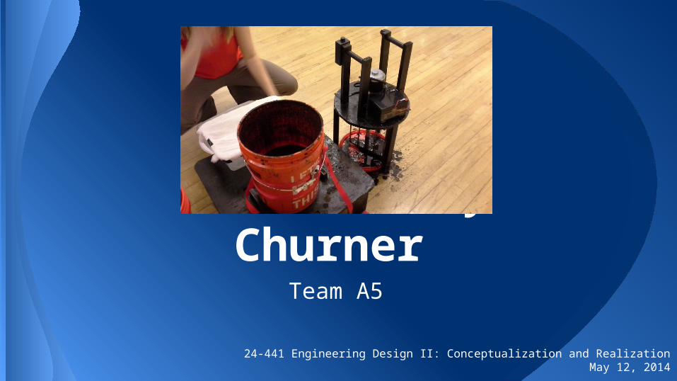
Soil Slurry Churner
24-441 Engineering Design II: Conceptualization and RealizationMay 12, 2014
Team A5

Miki Bassey: Miki Bassey is a robotics-loving Japanese-American mechanical engineer. After seeing the aftermath of the Fukushima disaster, she wanted to work on a project that would help. Miki worked on prototyping, making the Solidworks models and doing some of the hands-on work in the machine shop.
Kathryn Davis: Kathryn acted as team leader and did her best to help out with a little of everything. She worked on prototyping and CAD modeling, while taking charge of the analyses, heavy machining, and welding.
Brenna Flatley: Brenna’s work on the team was as well-rounded as her interests. She helped with woodworking, selected components, and worked on aesthetics. She was also in charge of the slurry samples and testing the effectiveness of mixing.
Clair Hann: A quiet powerhouse with a thirst to create awesomeness, Clair purchased and delivered large project materials. She also constructed the platform, designed the tilt-assist mechanism, and made the expo poster.
Catherine Rudnick: With a clever eye for detail, Catherine completed the house of quality, bill of materials, and cost analysis. She was in charge of electronic components and wiring, and aided prototype building.
The Team

In the wake of the Fukushima nuclear disaster, farmland surrounding the affected area was found to be contaminated with dangerous levels of radioactive Cesium. The government’s response to this was to completely remove the topsoil layer in these areas, which is very costly and wasteful.
Our project was inspired by research of Professor Masaru Mizoguchi at the University of Tokyo, who found that the radioactive Cesium particles had a tendency to attach to clay particles in soil. From this, he developed a method of systematically removing clay from farmland while retaining nutrient density in soil. To separate clay from soil, soil and water must �be churned into a homogenous mixture, then left to sit for several hours so the clay will separate, leaving the nutrient-rich silt. Mizoguchi’s method involves sending several workers into the fields to painstakingly agitate the soil using hand tools. This method removes about 80-90% of cesium, falling into national safety standards and allowing farms to begin producing quicker.
Problem Description

Although Mizoguchi’s method is effective at removing clay, we felt it could be best accomplished in self-contained system to be operated by fewer workers. Our opportunity lies in the ability to create a clay extraction system that is smaller than expensive industrial machinery, but more productive and less labor-intensive than hand-mixing methods.
Opportunity Statement

Creating a self-contained clay extraction system for large-scale use has many benefits in nuclear decontamination. Because we are designing a system that can be operated by a single user with many commonly available parts, we hope to solve the problems of areas in need of decontamination while using fewer resources and manpower. Separating clay in a contained but small-scale system reduces exposure to nuclear materials and hopefully would quicken the Japanese farmer’s return to production.
Motivation
Our market research focused on three specific groups that would find use in a system like ours. This group included Japanese farmers as mentioned before, as well as local potters and gardeners in the Pittsburgh area. From this, we approximated their priorities in a clay extraction system: •Potters - interested in extracting indigenous clay for pottery use
-Wanted a safe, cheap, and portable system-A system that could extract more clay in one iteration than by hand
•Gardeners in the Pittsburgh area - wished to reduce the acidity level from high clay concentrations present in local soil, while still retaining nutrient density
-Wanted a system that leaves nutrients in the soil-A safe system that easily extracts clay without requiring much heavy lifting
or labor
•Japanese farmers - interested in removing contaminated clay from soil and reducing waste. -Wanted a system that wastes less water than current methods
-A system that uses fewer resources than hand-mixing or heavy machinery
Market Research

At right is a selection of our design requirements (in no particular order). These have progressed from our initial stages in various ways including the removal of considerations for a self-moving system (see “Concept Generation and Evaluation”) and the addition of specific requirements that ensure the system’s usability in isolated or low-power conditions. Our complete requirements are described in full on the following page.
Design Requirements

End-User/Stakeholder Requirements•Ease of Use – The system should be easy to use and practical.
Operation should require less effort than current manual soil-mixing methods. Unnecessarily complicated operation should be avoided because it would deter users from adopting this new system.
•Portability – The system should be of an appropriate size and weight to be easily transferred from storage to field and between containers.
•Compatibility with Existing Equipment – The mixer is designed to fit a 5-gallon bucket, a standard bucket size many have already in their garages or gardens.
•Safety – There should be little risk of bodily harm to the end user. As this mechanism will require a significant amount of torque to operate, it is very important that the end user is prevented from getting any part of their person caught in the moving parts. To accomplish this, we will isolate the moving parts of the system from the user with a lid.
•Low Maintenance – This system should not require frequent maintenance or supervision to operate.
•Marketability- The system should be easily marketable to multiple types of consumers, including local farmers, industrial users, and artists.
System Requirements •Homogenous Mixing – It is of the utmost importance that the
mixer is able to achieve a homogenous mixture of water and soil. •Ruggedness – The system should be able to soils with various
compositions and perform consistently over extended use.
•Engine Isolation – The engine should be separate from the wet mixing portion of the system in order to prevent short circuits and engine damage.
Functional Requirements•Secures Bucket – Because of the rotational nature of our mixing
method, the system should be able hold the bucket in place so that only the mixing tines and soil solution move.
•Stabilizes Tilted Bucket - After mixing, the slurry must be poured in a controlled manner into a filtered reservoir for clay extraction.
•Prevents Spills – It is important that the water and soil stay contained in the bucket.
Environmental Requirements•Long Life Cycle – The system should be durable, such that it
can sustain multiple uses and be used for a long time.
•Effective Clay Extraction – Clay should be sufficiently removed from soil after cycling through the system.
Design Requirements

Our initial designs focused on mobile waterproof push-tillers. We quickly found that these designs were beyond the scope and budgetary constraints of our design course.
We were later inspired by the design of common concrete mixers. From this we decided to design a self-contained system and focus on the entire user interface, from mixing to settling and filtering. Shown below are examples of Pugh charts used to evaluate our various concepts based on the design requirements. All concepts were rated on a scale of -2 to 2 (represented in the charts by + and –’s), and net performance was based on the weighted sum of ratings for each criterion. We began by evaluating general concepts, as seen on the left. Once we decided to pursue a bucket based design, we perfomed a secondary evaluation to decide on a specific mixing mechanism. This secondary evaluation was performed at the same time as, and informed by, the activities of our first prototyping stage. This stage is explained on the following slide.
Concept Generation and Evaluation

To focus on developing a mixing attachment, we made several small-scale replicas of existing mixing tools using cardboard and wire. To simulate the different layers present in the material to be mixed, we tested the prototypes in clear buckets with color-separated layers of multicolored candies and judged each design by its ability to disturb the layers. The prototype mixers were each attached to a standard drill and rotated in the candy layers. Although this prototype was not an accurate portrayal of realistic mixing conditions, it helped us decide on the paddle-type mixing attachment because other designs showed no added mixing benefit for the additional manufacturing difficulty they incurred.
Prototype 1

Our second prototype consisted of a steel paddle which was driven directly from a rotational motor. The bucket was strapped into a tilt-assist mechanism, which consisted of a long hinge attached to the base. The motor and paddle were attached to a three-legged platform, which would then be lowered over the bucket using the attached handles. It was in this prototype that we found our paddle design was
over-engineered for durability. For the purposes of our design task, we found we did not need such a heavy paddle design, and decided that user experience would improve with a lighter paddle. While this prototype accomplished our main objective of mixing soil and water, it failed to do so safely as it lacked vibration dampening and paddle balancing. Because of the paddle’s weight, and because of the direct-drive motor receiving full power on starting, a slight off-centering of the mixing attachment led to violent jostling of the mechanism and inconsistent performance.
Prototype 2

The model shown on the far left is the virtual mock model of what we initially intended to construct for Prototype 2. Over the course of the prototyping period, changes to the paddle shape took place (as evidenced by the image on the right), and the handle design became more realistic. We abandoned the dual bucket platform because we felt that we could sufficiently demonstrate the highly movable nature of the system without explicitly showing the transition between two buckets. Further, an individually scaled final product would be unlikely to feature a dual platform and a largescale use of the system would have a more expansive setup with or without the platform’s aid, so a dual bucket prototype would not give an accurate representation of the final product system.
Virtual Mock Model

This flowchart details the desired functionality of our system.
Functional Decomposition
Visual signal that system is not running

We used the following metrics to judge our system’s performance:
•Homogenous consistency reached from operation• No large clumps of clay or soil
•Clay extraction comparable to hand mixing• Approximately 25% clay removed by volume
•Limited mixing time• 30 seconds from powered experimentation
The first two metrics were informed by our first round of experimentation. We wanted to compare the system to hand mixing, which is extremely thorough (extracted the 25% clay cited above). However, we also wanted mixing to occur much faster than by hand. Using the faster end of durations that potential users expressed interest in through market research, we developed our time goal.
Performance Metrics

In the course of finalizing our design, several analyses were undertaken. They will be addressed in the following order:
•Basic Static Analysis•Optimization•Fluid Analysis•Full FEA Simulation•Electrical Analysis
Engineering Analysis

Our basic static analysis was the basis of almost all subsequent analyses. The analysis was carried out to get an approximation for the required shaft thickness and the thickness of the paddle components (since, based off of successful mixing paddle designs, we were anticipating a mostly hollow design). Toward this end, however, we looked at a worst case scenario of the paddle being completely clogged with debris, which was effectively a paddle of solid cross-section. Additionally, a safety factor of 5 was enforced in all calculations. Both of these measures were taken to ensure the system’s safety as users interact with it so closely.
We began calculations by finding the force that the paddle would feel from drag in the material. We work under the assumption that this drag will be due to a uniform slurry because assuming a bucket full of soil would result in a paddle that is so overbuilt that it is too heavy for a user to repeatedly move comfortably and because the densities of soil and our particular slurry are similar enough that the difference is absorbed by our imposed safety factor. The drag force was found using the following equations:
Here, φ represents the solid weight percent, 54.6% for the purposes of our system (given the 50% volume of soil). CD is the drag coefficient due to the shape of the submerged body, 1.05 in this case. We agreed that a nominal velocity of 120 rpm would be suitable as an approximation of the lowest end of the range of speeds for blending mechanisms (low running speed for user safety).
Basic Static Analysis

To have a complete picture of the forces acting on the system, we must also consider the paddle’s inertia. This requires us to switch gears. Using material properties from matweb.com to model our material options (303 stainless steel, 1045 carbon steel, and 6061 aluminum), we perform a bending analysis on an individual paddle tine (modeled as a uniformly loaded double cantilever beam, given its welded connections to the paddle skeleton). Since the tines are angled in relation to the force from the material, this computational model is not completely accurate, but assuming complete facial contact with the material at all times results in a more conservative value than reality will require. We find the thickness by imposing an upper limit on the allowable deformation of the tine and solving the following system of equations:
In these equations, L is the length of the tines (10 inches), E is the material’s modulus of elasticity, w is the width of the tine (1.25 inches) and P is the force per unit of length applied to the tine, the “force” being the drag force. With the thickness in hand, we can easily find the mass of the paddle, followed by the paddle’s moment of inertia. Combining the inertial load with the drag force, we can use the following deflection equations to find the dimensions of the shaft (the first being another safety-imposed limit).
G is the shear modulus of elasticity for the material, T is the applied torque (found above), and L is the length of the shaft (18 inches). X is the length of the sides of the square cross-section portion of the shaft, and Δφ is the shaft’s angular deflection.
After all calculations are complete, we find that the aluminum requires more material to match the strength of either variation of steel, as one would expect. However, the mass of aluminum is significantly lower, even in the increased quantities. This is an important consideration given that the user will be lifting the system at times. With this in mind, it is apparent that aluminum is the ideal material for our application. With aluminum, the resulting dimensions are as follows:
Shaft Side Length/Diameter: 0.794 inches
Tine Thickness: 0.214 inches
Basic Static Analysis

One of the first steps in our design process was performing a parametric optimization for the specific aspects of the paddle design. Though this step included a stress analysis, these results were used solely for comparison to a control shape, a solid square paddle (shown right). The optimization was performed to optimize the number of interior tines on the paddle and their tilt angle with respect to the paddle’s mid plane. We investigated numbers of tines ranging from one to three and angles in the range of 5° to 60°. These variations were judged by their maximum Von Mises stress and minimum safety factor. At right is a table showing the results for each case, where performance was based on Factor of Safety. Cases are labeled such that the last number is the number of tines represented, and the preceding numbers are the tilt angle in degrees.
Optimization

All models involved a pin constraint around the main shaft to simulate the bearing setup that would be present, and the control paddle felt pressures on its mixing surfaces that simulated the resisting torque of the mixing material. However, the parameterized paddles were simulated with remote forces distributed along all relevant sections of the paddle.
We found the optimal scenario to be one interior tine per side (evenly spaced) tilted 60° from the mid plane. After this was complete, the results from the optimized configuration were compared to those of the control paddle. The former performed better than the latter, and so was the design with which we proceeded.
Optimization

We conducted a brief fluid analysis using FLUENT to confirm that moving forward with our desired speed was reasonable. Our performance metrics from early in the process stated that our goal was to achieve a homogenous mixture within 30 seconds, so in our model, we would be looking for an even distribution of soil at that time. The analysis model involved a small impellor and its angular velocity was set to match our given speed through a polynomial expansion. The model was set up such that initially the system contained a layer of soil (modeled with density values courtesy of engineeringtoolbox.com) underneath a layer of water. The mesh, shown top right, displays the soil in dark blue, and the water in grey. When the simulation was run, the soil was fairly well-distributed through the water at the end of one minute (see bottom right). However, due to limitations of skill and resources, and as one can see, this model is not entirely representative of the system as it will exist in practice. This simulation was used to inform the design process, but did not serve as a specific foundation for any subsequent decisions. Model was based off of “Using the Eulerian Multiphase Model for Granular Flow” tutorial from FLUENT, Inc. documentation.
Fluid Analysis

We carried out a brief analysis for the purpose of finding the specifications required of our electrical components to receive the results we’d been simulating. After determining the torque required to spin the paddle at the desired speed, we used this information to find our power requirements. The minimum power was found via:
Here, P is power, T is resisting torque due to drag, and ω is the angular velocity of the paddle. After we found that the optimized, non-solid paddle was the best design, an updated torque (due to the altered shape and moment of inertia) was found. From this, we found that the system required approximately 230.36 Watts of power.
After the motor was chosen, batteries, a switch, and a controller were chosen such that the rated amperage is not exceeded. The controller functionality allows the user to directly control the rate at which the motor accelerates, ensuring that the nominal acceleration (associated with the magnitude of the inertial torque) is not too high. Further, the ability to directly control the paddle acceleration drastically increases the user’s safety.
Electrical Analysis

Once we had established the form and dimensions of the prototype, we were prepared to move forward with the design. Via consultations with machinists, we learned that our initial paddle design, seen on the second Optimization slide, was not only impossible to fabricate with the means available to us, but also extremely difficult to create in industry. The complex form would drive up production time and costs for a product that would mix only marginally better than a much simpler design. With this in mind, we redesigned the paddle to a less curvaceous form. The redesign made some of our previous simplifications more valid, but we still proceeded to do a final FEA analysis.
This model is set up very similarly to the model used for the optimization: The circular section of the shaft is constrained such that it can only rotate about its long axis (simulating the conditions from the bearing and coupling attachment, which constrain all other degrees of freedom). The surfaces that are resisted by material as the paddle spins are loaded with uniform surface pressures, simulating the drag (calculated previously). The simpler design allows the pressures to be accurately applied along the surfaces, unlike the previous model, which involved approximation via remote forces. By way of the threaded connection between the paddle skeleton and shaft, and the welded connections within the paddle itself, none of the other portions were allowed to translate in the y-direction (constrains shown at right). The paddle was modeled with built in properties for 6061-T6 Aluminum, with isotropic elements. Strictly speaking, isotropic elements are not the best model for the welded areas, but they are good for the vast majority of the model. Small deflections were assumed because we imposed this condition when we designed the structure (our limits on bending and angular deflection).
Full FEA Simulation

At the conclusion of the simulation, the Von Mises stress distribution was as seen on the left. The maximum stress was 1046.68 psi in the shaft and 601.40 psi in the paddle itself. Both values are well below the yield strength of 6061 Aluminum (40000 psi), confirming that the paddle design is robust enough to be safe for users. Our final paddle design has an overall footprint of 10x10 inches to fill up the majority of a standard five gallon bucket, while still leaving space for mixing; a lightweight material for easy mobility; and a simple, robust geometry that all but prohibits unsafe failure while in use.
Full FEA Simulation
Purchased:•Bucket•Motor•Controller•Battery•Switch•Coupling•Bearing•Cheesecloth•Spring Hinge
Custom:•Cover with sealing tubing and supporting legs•Handles•Spacers between motor and lid•Aluminum Paddle
Design Parts
The parts used in our design are as follows:
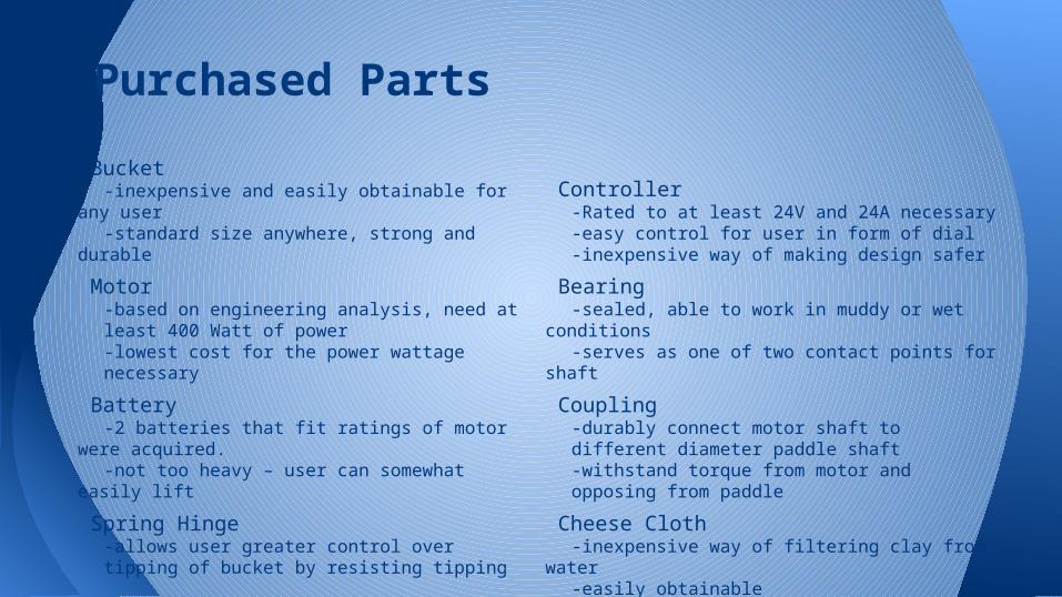
Bucket-inexpensive and easily obtainable for any user-standard size anywhere, strong and durable
Motor-based on engineering analysis, need at least 400 Watt of power-lowest cost for the power wattage necessary
Battery-2 batteries that fit ratings of motor were
acquired.-not too heavy – user can somewhat easily lift
Spring Hinge-allows user greater control over tipping of bucket by resisting tipping
Controller-Rated to at least 24V and 24A necessary-easy control for user in form of dial-inexpensive way of making design safer
Bearing-sealed, able to work in muddy or wet
conditions-serves as one of two contact points for shaft
Coupling-durably connect motor shaft to different diameter paddle shaft-withstand torque from motor and opposing from paddle
Cheese Cloth-inexpensive way of filtering clay from water-easily obtainable
Purchased Parts

Handles
-composed of 2”x1” wood blocks with wooden 1” dowels connecting them. Glued together.
Motor Support Spacers
-made with ¼” diameter aluminum threaded rod within ⅜” unthreaded aluminum spacer, each of these cut down to length
-nuts on either end of threaded rod secure cover and motor to spacer
Paddle
-welded aluminum stock together into paddle shape. ¾”x ¾” aluminum stock, after having part of length being milled down to ¾” diameter cylinder, is bolted into paddle shape. Washer included.
Platform
-⅝” thick plywood cut into 20” x 24” square
-supported by six 2” x 4” x 8” legs
-tilt-assist mechanism screwed onto platform
-trough for clay water can be placed next to platform
Cover
-⅝” plywood cut into 14¼” diameter circle with ¾” hole for shaft drilled in center
-similar 8.88” circle centered and attached
-plastic tubing is cut once down its length and encircles smaller plywood circle with epoxy
-three ¾”x ¾” x 15.5” legs are screwed onto cover
Custom-made Parts

Bill of Materials

The controller allows for two inputs from the motor and two from the battery. The switch is inserted into the circuit by being connected between the controller and the battery. Thus, the circuit can be completed just by flipping the switch, and once completed, the controller can change the speed of the motor.
Wiring Diagram


FMEA ApplicationsIn order to prevent:
• a paddle tine from breaking, we designed the tines thicker while maintaining the optimized shape.
• a corner of paddle from breaking or bending, we designed it with thicker cross-sections.
• a motor stalling or burning out, we used a motor with a higher rated power than required.
• shaft failure by excessive angular deflection, we used a thick shaft (via application of high safety factor).
• the axle from slipping, we plan to glue the set screws on the motor axle in place.
• the bucket from cracking, we sized the paddle such that it had sufficient clearance space with respect to the bucket wall and made the system self-centering.
• tilting mechanism from breaking, we will install a stronger spring hinge.
• the bucket spinning with paddle, we ensured the paddle had sufficient clearance and secured it to the tilting mechanism.
• the handles breaking, we would strengthen handles by thickening or reinforcing them.
Manufacturing and Assembly for Mass Production
Most of our design will be constructed from machined stock high-density polyethylene (HDPE) and acrylic, chosen for their respective costs and strengths. We will purchase acrylic stock in the proper sizes for the lid, the legs, and both parts of the handles for the lid. Acrylic was chosen over HDPE because this will undergo more vibration and stress than the platform. The platform, the legs, and the bar for the tilt assist for the platform will be made from HDPE to minimize cost. These will be machined to scale, as detailed in the Bill of Materials (BOM) and appendix. We will machine grips for the handles and then we will adhere the rounded acrylic cylinders into machined holes in handles. Assembly will include all fasteners and adhesive bonding, will all costs estimated in the BOM.
The paddle is fabricated by cutting pieces of stock aluminum to length for each linear section of the skeleton. The pieces for the top and bottom have square holes milled into them to house the shaft, which is then inserted into the holes. The shaft stays in this position while the paddle is welded together to keep the final paddle aligned.
In the lid, the bearing will be attached using a durable, strong adhesive, included in the lid price on the BOM. The motor will be bolted on through the holes in the acrylic with threaded spacers giving room for the coupler and axle. Finally, the gasket will be added on using an adhesive so that it is centered on the lid and can fit the bucket diameter.

Design For Manufacture and Assembly
We wanted to make our design both easier to manufacture and assemble. The number of parts we have is the least number we can have without compromising our structural elements. This increases time for manufacture but is necessary to reduce the time for assembly, which is a boon toward ease of use. We changed the material for many parts from wood to HDPE which increases manufacture time but decreases assembly time drastically and benefits aesthetics. The original paddle design made manufacture nearly impossible, and was redesigned. We have successfully achieved a balance between short and easy manufacturing and assembly methods with our final design.

Manufacturing and Assembling Final Prototype
Our final prototype was largely constructed out of wood. Everything we used wood for we would like to make out of acrylic or HDPE in the final product. We cut plywood for the platform and the lid. We then cut legs for the platform out of 2x4 lumber. The wooden legs that support the lid when not in use are made out of 2x2 stock wood. In the center of the lid, we drilled a hole for the axle and drilled a larger radius hole halfway through the board to nest the bearing. We added a smaller circle of plywood to the bottom of the lid and put tubing around it to create a gasket. The gasket insert is centered with respect to the lid and includes a corresponding center hole for the shaft. We also drilled three specifically positioned holes around the center for the motor attachment bolts. For the handles, we obtained 1x2 lumber and drilled clearance holes near the top. We then put a large wooden dowel through each pair of drilled 1x2s to make the handles. We then attached the two handles to the lid. The platform we attached the tilt assist which had a piece of 4x4 wood attached to a spring hinge. Then we added two wood stops to further constrain the bucket. These were made from short 1x2s laid on their sides. We then painted everything and waterproofed it. We made the paddle from aluminum and welded it together. We attached the paddle to a rectangular axle, that was made cylindrical on one end. This fit into a coupler that then fit onto the motor axle. We used nails to hold in the battery for the prototype but we will bracket it on in the final product. The switch and speed dial are attached to the handles. And then we had our prototype.
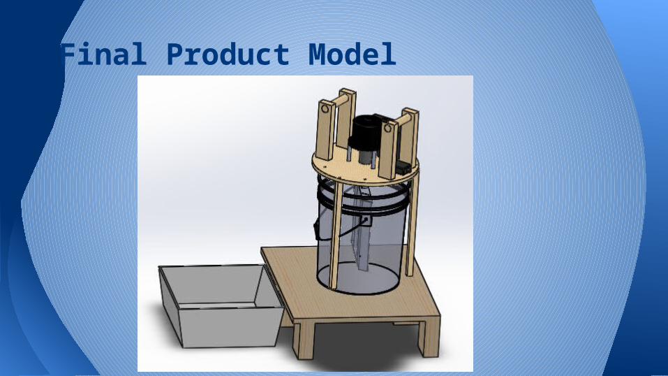
Final Product Model
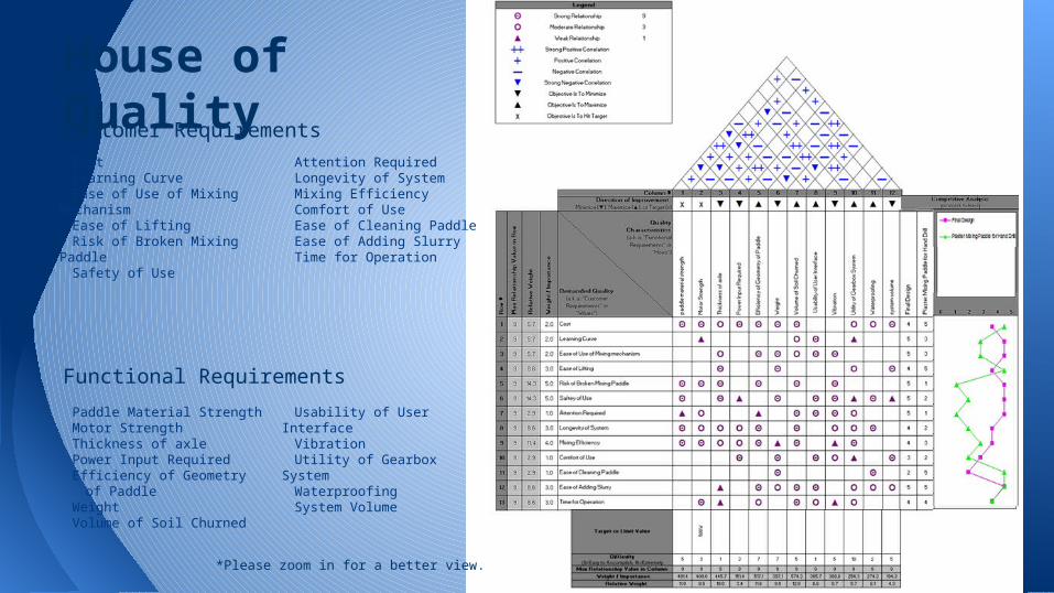
House of Quality
CostLearning CurveEase of Use of Mixing
MechanismEase of LiftingRisk of Broken Mixing PaddleSafety of UseAttention Required
Longevity of SystemMixing EfficiencyComfort of UseEase of Cleaning Paddle Ease of Adding Slurry Time for Operation
Paddle Material StrengthMotor StrengthThickness of axlePower Input RequiredEfficiency of Geometry of
PaddleWeight Volume of Soil Churned
Usability of User InterfaceVibration Utility of Gearbox SystemWaterproofingSystem Volume
Functional Requirements
Customer Requirements
*Please zoom in for a better view.

Engineering CharacteristicsThe three most important engineering characteristics for our design were the motor strength, the volume of
soil churned, and the geometry of our paddle. These characteristics were the main constraints on how our system would operate and what components and materials we chose. The worst case scenario of the paddle geometry, a solid rectangle of material, in an estimated highest volume of soil mixed gave us our motor strength. With these values, the majority of other dominant engineering characteristics are fully constrained, such as paddle material strength, thickness of the axle, power input required, and weight.
For our house of quality analysis, there are very few systems on the market with the same customer and design requirements. Currently no system has been made for the precise purpose of mixing soil and water to aid sedimentary transport.
A similar system in base functionality would be an electric drill attachment for mixing cement or plaster. This is composed of a paddle similar to ours, but much thinner and smaller. It is used for mixing cement and plaster for construction. This design is attached into the drill and then the user stands over a bucket with the paddle held in the mixture while the drill runs. The paddle is not centered and can easily damage the bucket. The design has also been reviewed by users as prone to breaking at the axle and paddle when under large loads. It is very light, cheap, and easy to clean, but lacks power and requires constant user input.
Competition in HOQ
Final Design HOQOur finalized design improved in many categories of user requirements. With the metal
of the paddle switched from steel to aluminum, the cost and weight of the system decreased. This provided comfort of use, ease of lifting, and cost to have better scores. The motor was able to turn at a faster rate due to the lighter material of the paddle, which increased the mixing efficiency as well. This also allowed less attention to be required on the system as there were much fewer vibrations at any speed. The speed controller increased the safety of the system, giving the user the ability to quickly stop the system or ramp up the speed from a standstill. The new gasket system allowed the entire system to self-center, so the entire mixing system could be lifted off the bucket with minimal user input. Adding the soil and water is now easier than the first iteration of the PT2 design due to the elimination of the need for a centering cone.
Overall, the final design ties or outranks the competition in every category besides cost, ease of cleaning and ease of lifting, both due to the larger scale of slurry that can be mixed and the size of the system itself.

Cost AnalysisFor our cost analysis, we assumed that our design would be best manufactured in
Japan, outside the Greater Tokyo area. This is an ideal location due to the proximity to our potential primary market of the Japanese farm workers and the ease of shipping to the United States for our secondary markets of gardening and art enthusiasts. It is also a good location for shipping, factory acquisition, and affordable labor.
Our estimated costs are determined through research in the retail prices of the components through vendors like McMaster-Carr, so on the manufacturing scale these prices could potentially be much lower due to bulk volume discount. All machining processes are performed by hand due to the estimated low production volume. Fixed costs, shipping, and packaging are based off of similarly sized industrial scales.
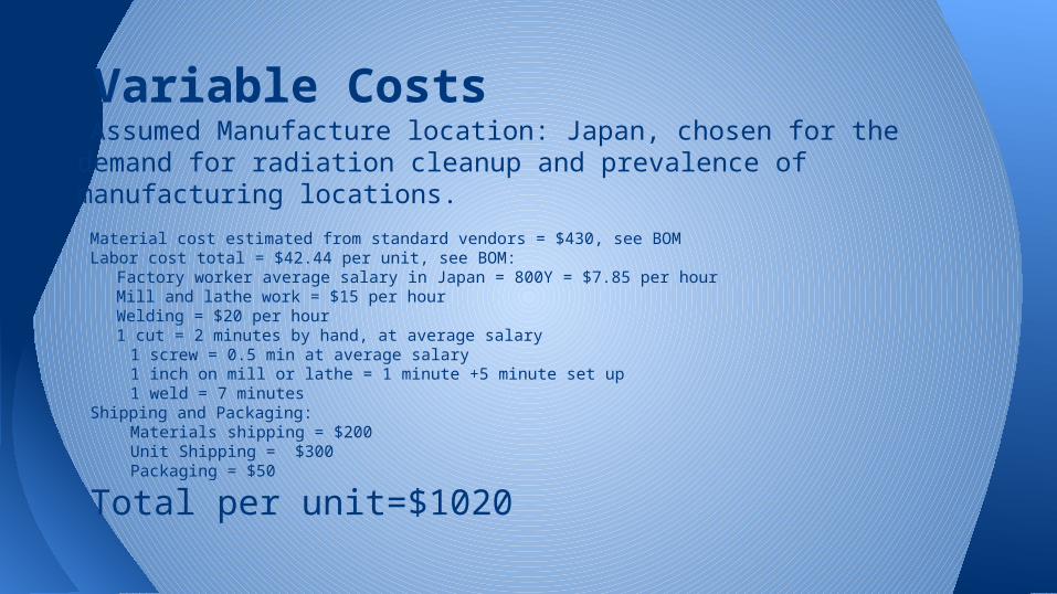
Variable CostsAssumed Manufacture location: Japan, chosen for the demand for
radiation cleanup and prevalence of manufacturing locations.
Material cost estimated from standard vendors = $430, see BOMLabor cost total = $42.44 per unit, see BOM:
Factory worker average salary in Japan = 800Y = $7.85 per hourMill and lathe work = $15 per hourWelding = $20 per hour1 cut = 2 minutes by hand, at average salary
1 screw = 0.5 min at average salary1 inch on mill or lathe = 1 minute +5 minute set up1 weld = 7 minutes
Shipping and Packaging:Materials shipping = $200Unit Shipping = $300 Packaging = $50
Total per unit=$1020

Fixed CostsAssumed Production Volume: <10,000 units/year due to the niche demand for the system. Low production volume therefore requires a smaller facility and less automated equipment.
Overhead Cost= Indirect Materials + Rent of facility + Utilities: Assumed to be a 30,000 square foot factory space in Japan:
Rent= 150 Yen per square foot per month (equivalent to a factory in LA area) = 4.5M Yen per month = $440,000
Utilities= 6330 Yen per month = $62 Indirect Materials=Welding material, adhesives, maintenance= $1000 per month
Non-machining Labor cost = 200 workers, at approximately $7.85/hour, $358,100 per month Equipment= Welding tools, Mills, Lathes, drill presses, band saws
Mills-$9,000Lathes- $15,000Drill Press- $3,400Band Saw - $5,300
Total Fixed Costs Per Month= $800,000

Total Cost AnalysisTotal cost per unit= $2,620 assuming 500 units produced each month. Equivalent cost of a large-drum cement mixer of similar mixing volume- $3,320
Cost Analysis conclusions- This is an appropriate estimate for such a large scale industrial tool.

TestingThe soil slurry churner was tested
multiple times at the expo. It did its job beautifully by silently but thoroughly mixing the soil and water. No mud splashed out during the mixing process, and the product was fully supported by its legs when not in use. Despite the constant use, there was no evidence of any fatigue or failure. Onlookers were impressed.
Finding conclusive results about the clay extraction required several hours of letting the mixture sit, which we were unable to do at the expo. However, after returning to the system later on, complete separation was observed. Success!

Dissemination of TechnologyThis product is easy to use, portable, and fits any standard 5 gallon bucket. It can be
used for a variety of purposes, from extracting local clay for pottery to decontaminating irradiated farmland. It is silent, and takes mere minutes to accomplish its mixing. Clay can be extracted on a large scale simply by setting up more buckets of soil and water.
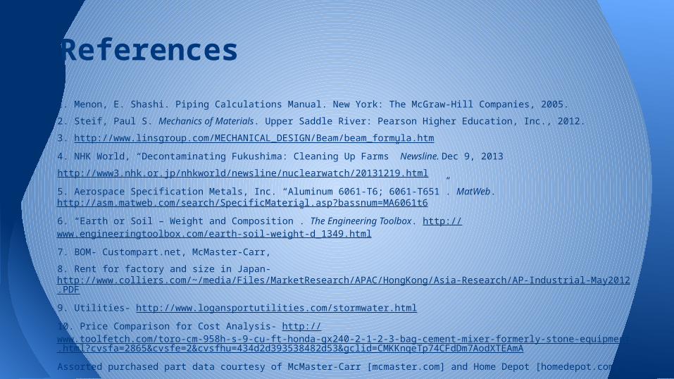
1. Menon, E. Shashi. Piping Calculations Manual. New York: The McGraw-Hill Companies, 2005.
2. Steif, Paul S. Mechanics of Materials. Upper Saddle River: Pearson Higher Education, Inc., 2012.
3. http://www.linsgroup.com/MECHANICAL_DESIGN/Beam/beam_formula.htm
4. NHK World, “Decontaminating Fukushima: Cleaning Up Farms” Newsline. Dec 9, 2013
http://www3.nhk.or.jp/nhkworld/newsline/nuclearwatch/20131219.html
5. Aerospace Specification Metals, Inc. “Aluminum 6061-T6; 6061-T651”. MatWeb. http://asm.matweb.com/search/SpecificMaterial.asp?bassnum=MA6061t6
6. “Earth or Soil – Weight and Composition”. The Engineering Toolbox. http://www.engineeringtoolbox.com/earth-soil-weight-d_1349.html
7. BOM- Custompart.net, McMaster-Carr,
8. Rent for factory and size in Japan- http://www.colliers.com/~/media/Files/MarketResearch/APAC/HongKong/Asia-Research/AP-Industrial-May2012.PDF
9. Utilities- http://www.logansportutilities.com/stormwater.html
10. Price Comparison for Cost Analysis- http://www.toolfetch.com/toro-cm-958h-s-9-cu-ft-honda-gx240-2-1-2-3-bag-cement-mixer-formerly-stone-equipment.html?cvsfa=2865&cvsfe=2&cvsfhu=434d2d393538482d53&gclid=CMKKnqeTp74CFdDm7AodXTEAmA
Assorted purchased part data courtesy of McMaster-Carr [mcmaster.com] and Home Depot [homedepot.com]
References

Motor Specifications
Appendix A: Purchased Component Specifications

Battery Specifications
Appendix A: Purchased Component Specifications
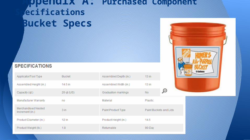
Bucket Specs
Appendix A: Purchased Component Specifications

Bearing Specs
Appendix A: Purchased Component Specifications

Coupling Specs

Controller Specs
Appendix A: Purchased Component Specifications

Cheesecloth
Appendix A: Purchased Component Specifications

Rocker Switch
Appendix A: Purchased Component Specifications

Spring Hinge
Appendix A: Purchased Component Specifications

Platform
Appendix B: Custom Component Documentation

Handle
Appendix B: Custom Component Documentation

Paddle
Appendix B: Custom Component Documentation

Cover
Appendix B: Custom Component Documentation

Supporting Legs
Appendix B: Custom Component Documentation

Cover, Tubing and Legs
Appendix B: Custom Component Documentation