solar charge controller network maximum power point · pdf filemodif y psw 30 default set 31...
TRANSCRIPT

eTracereTracereTracereTracer seriesseriesseriesseries—— NetworkNetworkNetworkNetwork MaximumMaximumMaximumMaximumPPPPowerowerowerower PPPPointointointoint TTTTrackingrackingrackingracking
SolarSolarSolarSolar ChargeChargeChargeCharge CCCControllerontrollerontrollerontroller
Models
ET2415N ET3415NET4415N ET6415N

FinalFinalFinalFinal interpretationinterpretationinterpretationinterpretation rightrightrightright ofofofof thethethethe manualmanualmanualmanual belongsbelongsbelongsbelongs totototo ourourourour company.company.company.company.AnyAnyAnyAny changeschangeschangeschanges withoutwithoutwithoutwithout priorpriorpriorprior noticenoticenoticenotice....
ContentsContentsContentsContents
1.0 Important Safety Information12.0 General Information2
2.1 Overview22.2 Models & Parameters42.3 Characteristics5
2.4 Optional Accessories73.0 Installation Instructions8
3.1 General Installation Notes83.2 Mounting93.3 Wiring10
4.0 Operation154.1 MPPT Technology154.2 Battery Charging Information174.3 LED Indication204.4 Display & Operation21
� Initialization21� Main Menu21� Monitoring21� Control Para23� System Para26� Network Para27� Clock Set29� Log Info29

� Modify Psw30
� Default Set31� The Others32
5.0 Networking & communication335.1 Introduction335.2 Setting345.3 Other Introductions40
6.0 Protections, Troubleshooting & Maintenance426.1 Protections426.2 Troubleshooting436.3 Maintenance45
7.0Warranty468.0 Specifications47Curves51Dimensions53

Page 1111
1111.0.0.0.0 ImportantImportantImportantImportant SafetySafetySafetySafety InformationInformationInformationInformationSave these instructions.This manual contains important safety, installation and operating instructions for
eTracer.
The following symbols are used throughout this manual to indicate potentially
dangerous conditions or mark important safety instructions, please take care when
meeting these symbols.
WARNING:WARNING:WARNING:WARNING: IIIIndicatesndicatesndicatesndicates aaaa potentiallypotentiallypotentiallypotentially dangerousdangerousdangerousdangerous condition.condition.condition.condition.
UseUseUseUse extremeextremeextremeextreme cautioncautioncautioncaution whenwhenwhenwhen performingperformingperformingperforming thisthisthisthis task.task.task.task.
CAUTION:CAUTION:CAUTION:CAUTION: IndicatesIndicatesIndicatesIndicates aaaa criticalcriticalcriticalcritical procedureprocedureprocedureprocedure forforforfor safesafesafesafe andandandand properproperproperproper
ooooperationperationperationperation ofofofof thethethethe controllercontrollercontrollercontroller....
NOTE:NOTE:NOTE:NOTE: IndicatesIndicatesIndicatesIndicates aaaa procedureprocedureprocedureprocedure orororor functionfunctionfunctionfunction thatthatthatthat isisisis importantimportantimportantimportant forforforfor thethethethe
ssssafeafeafeafe andandandand properproperproperproper operationoperationoperationoperation ofofofof thethethethe controller.controller.controller.controller.
General Safety Information
·Read all of the instructions and cautions in the manual before beginning installation.·There are no user serviceable parts inside the eTracer. Do not disassemble or attemptto repair the controller.
·Mount the eTracer indoors. Prevent exposure to the elements and do not allow waterto enter the controller.
·Please install controller in ventilated places, the temperature of heat sink may bequite high when working.
·Install external fuses/breakers as required.·Disconnect the solar module and fuse/breakers near to battery before installing oradjusting the eTracer.
·Confirm that power connections are tightened to avoid excessive heating from loose

Page 2222
connection.
2222.0.0.0.0 GeneralGeneralGeneralGeneral InformationInformationInformationInformation2.12.12.12.1 OverviewOverviewOverviewOverview
Thank you for selecting the eTracer controller. With the features of industrial class
product of high efficiency and reliability, the controller is a high-end product based on
multiphase synchronous rectification technology. The features are listed below:
·12V/24V/36V/48V auto work
·Excellent EMC design, thermal design and nature air cooling
·The first tracking to the maximum power point of solar modules in 15 seconds or
less, tracking efficiency of 99% or higher
·Multiphase synchronous rectification technology impels peak conversion efficiency
to 98%
·Multiphase power decentralized control can also make small power charging be high
effective, improve the capacity of generating
·High speed and performance of the double processors architecture, improve the
response speed and optimize the performance of the system
·Multiphase control technology, optimizes charging current smoothness, reduces
ripple, and improves the system generating efficiency
·Humanized browser interface, 128*64 dot-matrix LCD intuitively displays data and
state, many button combinations for easy operation, both Chinese and English
interface to choose from
·RS232, CAN BUS and Ethernet 3 kinds of communication way to meet different
occasions of demand as far as possible
·Sealed, Gel and Flooded battery option
·Three stages of optimizing charging control
·Protection: over heat, over charging, PV short circuit and PV (battery) revered

Page 3333
The controller features the built-in blur intelligent control algorithm that maximizes
the energy from the solar module(s) and charge the battery.
The controller charging process has been optimized for long battery life and improved
system performance. The comprehensive self-diagnostics and electronic protection
functions can prevent damage from installation mistakes or system faults.
Although the controller is very simple to configure and use, please take your time to
read the operator's manual and become familiar with the controller. This will help you
make full use of all the functions and improve your PV system.

Page 4444
2.22.22.22.2ModelsModelsModelsModels &&&& ParametersParametersParametersParametersMax. PV input voltage 150Vdc********
Standard RS232, CAN BUS and ETHERNET communication interface
ET2415N
� Rated continuous charging current 20A
� Max. PV input power 1040W
� 12V/24V/36V/48V system voltage auto work****
ET3415N
� Rated continuous charging current 30A
� Max. PV input power 1600W
� 12V/24V/36V/48V system voltage auto work****
ET4415N
� Rated continuous charging current 45A
� Max. PV input power 2400W
� 12V/24V/36V/48V system voltage auto work****
ET6415N
� Rated continuous charging current 60A
� Max. PV input power 3200W
� 12V/24V/36V/48V system voltage auto work****

Page 5555
* Every time start up the controller, system voltage automatically identified, do notneed your any operation or setting.
******** Array voltage should never exceed maximum PV input voltage. Refer to the solarmodule documentation to determine the highest expected array Voc (open circuitvoltage) as defined by the lowest expected ambient temperature for the systemlocation.
2.32.32.32.3 CCCCharacteristicsharacteristicsharacteristicsharacteristics
2
3
4
5
6
1
11
12 13 14 15 16

Page 6666
Figure 2-1 Characteristics
1111 –––– HeatHeatHeatHeat SinkSinkSinkSink
Inductance and MOSFET of heat through aluminum heat sink to dissipate.
2222 –––– LCDLCDLCDLCD
Data of displaying interface.
3333 –––– BatteryBatteryBatteryBattery IndicatorIndicatorIndicatorIndicator
An LED indicator shows battery status.
4444 –––– ChargingChargingChargingCharging IndicatorIndicatorIndicatorIndicator
An LED indicator shows charging or not.
5555 –––– FaultsFaultsFaultsFaults IndicatorIndicatorIndicatorIndicator
An LED indicator shows controller faults.
6666 –––– ButtonsButtonsButtonsButtons
Browse or modify all parameters.
7777 –––– SerialSerialSerialSerial RS-232RS-232RS-232RS-232 PortPortPortPort ((((DB9DB9DB9DB9))))
Monitor controller by PC or update software.
8888 –––– EEEEthernetthernetthernetthernet PortPortPortPort ((((RJ45RJ45RJ45RJ45))))
Connect Ethernet, monitor controller remotely by network.
9999 –––– SolarSolarSolarSolar polaritypolaritypolaritypolarity reversedreversedreversedreversed IndicatorIndicatorIndicatorIndicator
An LED indicator shows solar modules positive and negative reversed.
8
9++++++++ ---- ----
+----
7
10

Page 7777
10101010 –––– RemoteRemoteRemoteRemote TemperatureTemperatureTemperatureTemperature SensorSensorSensorSensor PortPortPortPort (MC1.5.3.81-2L)(MC1.5.3.81-2L)(MC1.5.3.81-2L)(MC1.5.3.81-2L)
Connect RTS, Measure battery temperature to make temperature compensation.
11111111 –––– RemoteRemoteRemoteRemote BatteryBatteryBatteryBattery VoltageVoltageVoltageVoltage SenseSenseSenseSense PortPortPortPort (MC1.5.3.81-2L)(MC1.5.3.81-2L)(MC1.5.3.81-2L)(MC1.5.3.81-2L)
Connect RBVS, Measure battery voltage accurately.
11112222 –––– CANCANCANCAN BUSBUSBUSBUS PortPortPortPort (MC1.5.3.81-4L)(MC1.5.3.81-4L)(MC1.5.3.81-4L)(MC1.5.3.81-4L)
Communicate with our other CAN BUS devices.
11113333 –––– SolarSolarSolarSolar PositivePositivePositivePositive TerminalTerminalTerminalTerminal (red)(red)(red)(red)
Connect to solar module(s) positive (+) terminal.
11114444 –––– SolarSolarSolarSolar NegativeNegativeNegativeNegative TerminalTerminalTerminalTerminal (black)(black)(black)(black)
Connect to solar module(s) negative (-) terminal.
11115555 –––– BatteryBatteryBatteryBattery NegativeNegativeNegativeNegative TerminalTerminalTerminalTerminal (black)(black)(black)(black)
Connect to battery negative (-) terminal.
11116666 –––– BatteryBatteryBatteryBattery PositivePositivePositivePositive TerminalTerminalTerminalTerminal (red)(red)(red)(red)
Connect to battery positive (+) terminal.
2.2.2.2.4444 OptionalOptionalOptionalOptional AccessoriesAccessoriesAccessoriesAccessories
RemoteRemoteRemoteRemote MeterMeterMeterMeter ((((ModelModelModelModel:::: MT-100MT-100MT-100MT-100))))
The digital remote meter displays system operating information, error indications, and
self-diagnostics read-out. Information is displayed on a backlit LCD display. The
large numerical display and icons are easy to read and large buttons make navigating
the meter menus easy. The meter can be flush mounted in a wall or surface mounted
using the mounting frame (included). The MT-100 is supplied with 2m of cable and a
mounting frame. The MT-100 connects to theMC1.5.3.81-4LMC1.5.3.81-4LMC1.5.3.81-4LMC1.5.3.81-4L port (12 th) on the
controller.
RemoteRemoteRemoteRemote TemperatureTemperatureTemperatureTemperature SensorSensorSensorSensor ((((ModelModelModelModel:::: TSTSTSTS----RRRR))))
Acquiring of battery temperature for undertaking temperature compensation of control
parameters, the standard length of the cable is 2m (can be customized if want longer).
The TS-R connects to theMC1.5.3.81-2LMC1.5.3.81-2LMC1.5.3.81-2LMC1.5.3.81-2L port (10 th) on the controller.

Page 8888
3.03.03.03.0 InstallationInstallationInstallationInstallation InstructionsInstructionsInstructionsInstructions3333....1111 GeneralGeneralGeneralGeneral InstallationInstallationInstallationInstallation NotesNotesNotesNotes
·Read through the entire installation section first before beginning installation.
·Be very careful when working with batteries. Wear eye protection. Have fresh water
available to wash and clean any contact with battery acid.·Uses insulated tools and avoid placing metal objects near the batteries.
·Explosive battery gasses may be present during charging. Be certain there is
sufficient ventilation to release the gasses.·Avoid direct sunlight and do not install in locations where water can enter the
controller.
·Loose power connections and/or corroded wires may result in resistive connections
that melt wire insulation, burn surrounding materials, or even cause fire. Ensure
tight connections and use cable clamps to secure cables and prevent them from
swaying in mobile applications.·Use with Gel, Sealed or Flooded batteries only.

Page 9999
·Battery connection may be wired to one battery or a bank of batteries. The following
instructions refer to a singular battery, but it is implied that the battery connection
can be made to either one battery or a group of batteries in a battery bank.
·Multiple same models of controllers can be installed in parallel on the same battery
bank to achieve higher charging current. Each controller must have its own solar
module(s).·Select the system cables according to 3A/mm2 or less current density.
3.23.23.23.2MountingMountingMountingMounting
NOTE:NOTE:NOTE:NOTE: WhenWhenWhenWhen mountingmountingmountingmounting thethethethe eTracer,eTracer,eTracer,eTracer, ensureensureensureensure freefreefreefree airairairair throughthroughthroughthrough thethethethe controllercontrollercontrollercontroller heatheatheatheat
sinksinksinksink fins.fins.fins.fins. ThereThereThereThere shouldshouldshouldshould bebebebe atatatat leastleastleastleast 150mm150mm150mm150mm ofofofof clearanceclearanceclearanceclearance aboveaboveaboveabove andandandand
belowbelowbelowbelow thethethethe controllercontrollercontrollercontroller totototo allowallowallowallow forforforfor cooling.cooling.cooling.cooling. IfIfIfIf mountedmountedmountedmounted inininin anananan
enclosure,enclosure,enclosure,enclosure, ventilationventilationventilationventilation isisisis highlyhighlyhighlyhighly recommendedrecommendedrecommendedrecommended....
WARNING:WARNING:WARNING:WARNING: RiskRiskRiskRisk ofofofof explosion!explosion!explosion!explosion! NeverNeverNeverNever installinstallinstallinstall thethethethe eTracereTracereTracereTracer inininin aaaa sealedsealedsealedsealed
encloseencloseencloseenclose withwithwithwith floodedfloodedfloodedflooded batteries!batteries!batteries!batteries! DoDoDoDo notnotnotnot installinstallinstallinstall inininin aaaa confinedconfinedconfinedconfined areaareaareaarea wherewherewherewhere
batterybatterybatterybattery gasgasgasgas cancancancan accumulate.accumulate.accumulate.accumulate.
Step 1: Choose Mounting Location
Locate the eTracer on a vertical surface protected from direct sun, high temperature,
and water.
Step 2: Check for Clearance

Page 10101010
Place the eTracer in the location where it will be mounted. Verify that there is
sufficient room to run wires and that there is sufficient room above and below the
controller for air flow.
Figure 3-1 Mounting and cooling
Step 3: Mark Holes
Use a pencil or pen to mark the four (4) mounting hole locations on the mounting
surface.
Step 4: Drill Holes
Remove the controller and drill four sizeable holes in the marked locations.
Step 5: Secure Controller
Place the controller on the surface and align the mounting holes with the drilled holes
in step 4. Secure the controller in place using the mounting screws.
Cool air
Warm airAt least
150mm
At least
150mm

Page 11111111
3.33.33.33.3WiringWiringWiringWiring
NOTE:NOTE:NOTE:NOTE: AAAA recommendedrecommendedrecommendedrecommended connectionconnectionconnectionconnection orderorderorderorder hashashashas beenbeenbeenbeen providedprovidedprovidedprovided forforforfor
maximummaximummaximummaximum safetysafetysafetysafety duringduringduringduring installation.installation.installation.installation.
NOTE:NOTE:NOTE:NOTE: DoDoDoDo notnotnotnot entangleentangleentangleentangle allallallall wiringwiringwiringwiring togethertogethertogethertogether,,,, communicationcommunicationcommunicationcommunication lineslineslineslines andandandand
powerpowerpowerpower lineslineslineslines shouldshouldshouldshould bebebebe asasasas farfarfarfar awayawayawayaway asasasas possible,possible,possible,possible, totototo preventpreventpreventprevent interferinginterferinginterferinginterfering
communicationcommunicationcommunicationcommunication signalsignalsignalsignal transmission.transmission.transmission.transmission.
NOTE:NOTE:NOTE:NOTE: TheTheTheThe eTracereTracereTracereTracer isisisis aaaa negativenegativenegativenegative groundgroundgroundground controller.controller.controller.controller. AnyAnyAnyAny negativenegativenegativenegative
connectionconnectionconnectionconnection ofofofof solarsolarsolarsolar orororor batterybatterybatterybattery cancancancan bebebebe earthearthearthearth groundedgroundedgroundedgrounded asasasas required.required.required.required.
GroundingGroundingGroundingGrounding isisisis recommended.recommended.recommended.recommended.
CAUTION:CAUTION:CAUTION:CAUTION: ForForForFor mobilemobilemobilemobile applications,applications,applications,applications, bebebebe suresuresuresure totototo securesecuresecuresecure allallallall wiring.wiring.wiring.wiring. UseUseUseUse
cablecablecablecable clampsclampsclampsclamps totototo preventpreventpreventprevent cablescablescablescables fromfromfromfrom swayingswayingswayingswaying whenwhenwhenwhen thethethethe vehiclevehiclevehiclevehicle isisisis inininin
motion.motion.motion.motion. UnsecuredUnsecuredUnsecuredUnsecured cablescablescablescables createcreatecreatecreate looselooselooseloose andandandand resistiveresistiveresistiveresistive connectionsconnectionsconnectionsconnections whichwhichwhichwhich
maymaymaymay leadleadleadlead totototo excessiveexcessiveexcessiveexcessive heatingheatingheatingheating and/orand/orand/orand/or fire.fire.fire.fire.
StepStepStepStep 1:1:1:1: RemoteRemoteRemoteRemote TemperatureTemperatureTemperatureTemperature SensorSensorSensorSensor ConnectionConnectionConnectionConnection
NOTE:NOTE:NOTE:NOTE: TheTheTheThe controllercontrollercontrollercontroller willwillwillwill notnotnotnot performperformperformperform temperaturetemperaturetemperaturetemperature compensacompensacompensacompensationtiontiontion forforforfor
chargingchargingchargingcharging parametersparametersparametersparameters ifififif thethethethe TSTSTSTS----RRRR isisisis notnotnotnot used.used.used.used.
CAUTION:CAUTION:CAUTION:CAUTION: EquipmentEquipmentEquipmentEquipment DamageDamageDamageDamage!!!! NeverNeverNeverNever placeplaceplaceplace thethethethe temperaturetemperaturetemperaturetemperature sensorsensorsensorsensor
insideinsideinsideinside aaaa battery.battery.battery.battery. BothBothBothBoth thethethethe TSTSTSTS----RRRR andandandand thethethethe batterybatterybatterybattery willwillwillwill bebebebe damaged.damaged.damaged.damaged.
The included remote temperature sensor TS-R is recommended for effective
temperature compensated charging. Connect the TS-R to theMC1.5.3.81-2LMC1.5.3.81-2LMC1.5.3.81-2LMC1.5.3.81-2L port
(10 th) on the controller (see figure 2-1). There is no polarity, so either wire (+ or -) can
be connected to either screw terminal. Separate installation instruction is provided
inside the TS-R bag. No damage will occur if connect the TS-R to the remote battery
voltage sense port, but the connection will not be recognized.

Page 12121212
StepStepStepStep 2:2:2:2: RemoteRemoteRemoteRemote BatteryBatteryBatteryBattery VoltageVoltageVoltageVoltage SensSensSensSenseeee ConnectionConnectionConnectionConnection
NOTE:NOTE:NOTE:NOTE: WhenWhenWhenWhen connecting,connecting,connecting,connecting, paypaypaypay attentionattentionattentionattention totototo ““““++++”””” (11(11(11(11thththth popopoportrtrtrt’’’’ssss top)top)top)top) andandandand ““““----””””(11(11(11(11thththth portportportport’’’’ssss bottom).bottom).bottom).bottom).
The voltage at the battery connection on the controller may differ slightly from the
voltage directly at the battery bank terminals due to connection and cable resistance.
The remote battery voltage sense connection enables the controller to measure the
battery terminal voltage precisely with small gauge wires that carry very little current,
and thus have no voltage drop. Connect the remote battery voltage sense wires to the
MC1.5.3.81-4LMC1.5.3.81-4LMC1.5.3.81-4LMC1.5.3.81-4L port (11th) on the controller (see figure 2-1). Pay attention to “+” and
“-” positions. A battery voltage sense connection is not required to operate your
controller, but it is recommended for best performance.
The voltage sense wires should be cut to length as required to connect the battery to
the voltage sense terminal. The wire size can range from 0.25 to 1.0 mm2 (24 to 16
AWG). The maximum length allowed for each battery voltage sense wire is 30m. A
twisted pair cable is recommended but not required.
Be careful to connect the battery positive (+) terminal to the voltage sense positive (+)
terminal, the battery negative (-) terminal to the voltage sense negative (-) terminal.
No damage will occur if the polarity is reversed, but the controller cannot read a
reversed sense voltage. Connecting the voltage sense wires to the RTS terminals will
cause an alarm.
StepStepStepStep 3:3:3:3: NetworkNetworkNetworkNetwork ConnectionConnectionConnectionConnection
WARNING:WARNING:WARNING:WARNING: ShockShockShockShock HazardHazardHazardHazard!!!! TheTheTheThe nnnnetworketworketworketwork cablescablescablescables andandandand thethethethe powerpowerpowerpower
conductorsconductorsconductorsconductors mustmustmustmust bebebebe asasasas farfarfarfar awayawayawayaway asasasas possible.possible.possible.possible.
NOTE:NOTE:NOTE:NOTE: ItItItIt isisisis advisedadvisedadvisedadvised totototo connectconnectconnectconnect thethethethe networknetworknetworknetwork cablescablescablescables beforebeforebeforebefore poweringpoweringpoweringpowering on.on.on.on.

Page 13131313
Three kinds of communication are provided as RS-232, CAN BUS and Ethernet. You
can monitor the controller on your PC or update software through RS-232 connection.
The controller is allowed to communicate with remote meter (MT-100) or our other
devices by CAN BUS. The controller also can be monitored via the internet. Refer to
section 6.0 for more information about Ethernet.···· RS-232RS-232RS-232RS-232 Connection:Connection:Connection:Connection:The serial RS-232 port is a standard 9-pin (DB9) male connector. Tighten the screw
on both sides of female connector in case that the female connector loosens or falls off
when data transmits. Refer to 9th port on the controller in the figure 2-1.
···· CANCANCANCAN BUSBUSBUSBUS Connection:Connection:Connection:Connection:If you have purchased CAN BUS equipment, connect it reliably. Refer to 12th port on
the controller in the figure 2-1.
···· EthernetEthernetEthernetEthernet Connection:Connection:Connection:Connection:
The Ethernet port is a standard RJ-45 connector. Use twisted pair cable and RJ-45
plug. Connect RJ-45 plug to the port carefully to avoid damaging it. Refer to 8th port
on the controller in the figure 2-1.
StepStepStepStep 4:4:4:4: PowerPowerPowerPower ConnectionConnectionConnectionConnection
WARNING:WARNING:WARNING:WARNING: RiskRiskRiskRisk ofofofof electricelectricelectricelectric sssshock!hock!hock!hock! UseUseUseUse fusesfusesfusesfuses orororor breakerbreakerbreakerbreakerssss inininin solarsolarsolarsolar andandandand
batterybatterybatterybattery circuitscircuitscircuitscircuits isisisis recommendedrecommendedrecommendedrecommended,,,, andandandand makemakemakemake themthemthemthem keepkeepkeepkeep OFFOFFOFFOFF statestatestatestate bbbbeforeeforeeforeefore
connection.connection.connection.connection.
WARNING:WARNING:WARNING:WARNING: RiskRiskRiskRisk ofofofof electricelectricelectricelectric sssshock!hock!hock!hock! ExerciseExerciseExerciseExercise cautioncautioncautioncaution whenwhenwhenwhen handlinghandlinghandlinghandling
solarsolarsolarsolar wiring.wiring.wiring.wiring. TheTheTheThe solarsolarsolarsolar module(s)module(s)module(s)module(s) highhighhighhigh voltagevoltagevoltagevoltage outputoutputoutputoutput cancancancan causecausecausecause severesevereseveresevere
shockshockshockshock orororor injury.injury.injury.injury. PayPayPayPay moremoremoremore attentionattentionattentionattention forforforfor it.it.it.it.
WARNING:WARNING:WARNING:WARNING: RiskRiskRiskRisk ofofofof explosionexplosionexplosionexplosion orororor fire!fire!fire!fire! NeverNeverNeverNever shortshortshortshort circuitcircuitcircuitcircuit batterybatterybatterybattery
positivepositivepositivepositive (+)(+)(+)(+) andandandand negativenegativenegativenegative (-)(-)(-)(-) orororor cablescablescablescables....

Page 14141414
···· BatteryBatteryBatteryBattery Connection:Connection:Connection:Connection:
Connect a fuse in series in the battery circuit, and select it according to the controller
rated current of 1.25 to 2 times. Make it keep OFF state before connection. Connect
battery negative (black) to the 15th port and positive (red) to the 16th port on the
controller in the figure 2-1.
···· SSSSolarolarolarolar Module(s)Module(s)Module(s)Module(s) Connection:Connection:Connection:Connection:
Connecting a breaker in series in the solar circuit is recommended, and select it
according to the controller rated current of 1.25 to 2 times. Make it keep OFF state
before connection. Connect solar positive (red) to the 13 th port and negative (black) to
the 14 th port on the controller in the figure 2-1.
If you have connected the battery and solar according to the above steps, please
confirm that there is no loose connections or error connections.
There will be no damage to the controller if battery itself or (and) solar itself
connection reverses due to carelessness.
StepStepStepStep 5:5:5:5: Power-UpPower-UpPower-UpPower-Up
NOTE:NOTE:NOTE:NOTE: OnlyOnlyOnlyOnly useuseuseuse thethethethe batterybatterybatterybattery terminalterminalterminalterminal’’’’ssss powerpowerpowerpower sourcesourcesourcesource totototo startstartstartstart andandandand
operateoperateoperateoperate thethethethe controller.controller.controller.controller. TheTheTheThe controllercontrollercontrollercontroller willwillwillwill notnotnotnot operateoperateoperateoperate onlyonlyonlyonly fromfromfromfrom solarsolarsolarsolar
input.input.input.input.
· Confirm that all connections are correct especially the Solar and Battery
polarities.
· Turn the battery disconnect fuse on first. Observe that whether the battery
LED’s indicate a successful start-up, LCD interface initialization correct. (refer
to section 4.0)
· Confirm battery power-up correct and then turn the solar disconnect on. If the
solar module(s) is in full sunlight, the controller will begin charging.

Page 15151515
· If the battery LED error exists or LCD interface alarms, please refer to section
5.0 for troubleshooting.
4.04.04.04.0 OperationOperationOperationOperation
4444....1111 MPPTMPPTMPPTMPPTTechnologyTechnologyTechnologyTechnology
The eTracer utilizes Maximum Power Point Tracking technology to extract maximum
power from the solar module(s). The tracking algorithm is fully automatic and does
not require user adjustment. eTracer technology will track the array maximum power
point voltage (Vmp) as it varies with weather conditions, ensuring that maximum
power is harvested from the array through the course of the day.
····CurrentCurrentCurrentCurrent BoostBoostBoostBoost
In many cases, eTracer MPPT technology will “boost” the solar charge current. For
example, a system may have 8 Amps of solar current flowing into the eTracer and 10
Amps of charge current flowing out to the battery. The eTracer does not create current!
Rest assured that the power into the eTracer is the same as the power out of the
eTracer. Since power is the product of voltage and current (Volts×Amps), the
following is true****:
(1) Power Into the eTracer =Power Out of the eTracer
(2) Volts In×Amps In=Volts Out×Amps Out
**** Assuming 100% efficiency. Actually, the losses in wiring and conversion exist.
If the solar module’s Vmp is greater than the battery voltage, it follows that the
battery current must be proportionally greater than the solar input current so that input
and output power are balanced. The greater the difference between the maximum
power voltage and battery voltage, the greater the current boost. Current boost can be

Page 16161616
substantial in systems where the solar array is of a higher nominal voltage than the
battery.
····AnAnAnAn AdvantageAdvantageAdvantageAdvantage OverOverOverOver TraditionalTraditionalTraditionalTraditional ControlControlControlControlllllersersersers
Traditional controllers connect the solar module directly to the battery when
recharging. This requires that the solar module operate in a voltage range that is below
the module’s Vmp. In a 12V system for example, the battery voltage may range from
11-15Vdc but the module’s Vmp is typically around 16 or 17V.
Figure 4-1 shows a typical current VS. voltage output curve for a nominal 12V
off-grid module.
Current VS. Voltage in 12V system Output power in 12V system
Figure 4-1 Nominal 12V Solar Module I-V curve and output power graph
The array Vmp is the voltage where the product of current and voltage (Amps×Volts)
is greatest, which falls on the “knee” of the solar module I-V curve as shown in
Figure4-1. Because Traditional controllers do not operate at the Vmp of the solar
modules(s), energy is wasted that could otherwise be used to charge the battery and
power system loads. The greater the difference between battery voltage and the Vmp
of the module, the more energy is wasted.
eTracer MPPT technology will always operate at the Vmp resulting in less wasted
energy compared to traditional controllers.
Typical BatteryVoltage Range
MaximumPowerPoint Traditional
ControllerOperating Range
eTracerMaximumPowerPoint

Page 17171717
····ConditionsConditionsConditionsConditions ThatThatThatThat LimitsLimitsLimitsLimits thethethethe EffectivenessEffectivenessEffectivenessEffectiveness ofofofof MPPTMPPTMPPTMPPT
The Vmp of a solar module decreases as the temperature of the module increases. In
very hot weather, the Vmp may be close or even less than battery voltage. In this
situation, there will be very little or no MPPT gain compared to traditional controllers.
However, systems with modules of higher nominal voltage than the battery bank will
always have an array Vmp greater than battery voltage. Additionally, the savings in
wiring due to reduced solar current make MPPT worthwhile even in hot climates.4444....2222 BatteryBatteryBatteryBattery ChargingChargingChargingCharging InformationInformationInformationInformation
The eTracer has a 4-stage battery charging algorithm for rapid, efficient, and safe
battery charging.
Figure 4-2 eTracer charging algorithm····BulkBulkBulkBulk ChargeChargeChargeCharge
In this stage, the battery voltage has not yet reached boost voltage and 100% of
available solar power is used to recharge the battery.
····BoostBoostBoostBoost ChargeChargeChargeCharge
When the battery has recharged to the Boost voltage setpoint, constant-voltage
regulation is used to prevent heating and excessive battery gassing. The Boost stage
remains 120 minutes and then goes to Float Charge. Every time when the controller is

Page 18181818
powered on, if it detects neither over discharged nor overvoltage, the charging will
enter into boost charging stage.
····FloatFloatFloatFloat ChargeChargeChargeCharge
After the Boost voltage stage, Tracer will reduce the battery voltage to float voltage
setpoint. When the battery is fully recharged, there will be no more chemical reactions
and all the charge current transmits into heat and gas at this time. Then the Tracer
reduces the voltage to the floating stage, charging with a smaller voltage and current.
It will reduce the temperature of battery and prevent the gassing, also charging the
battery slightly at the same time. The purpose of Float stage is to offset the power
consumption caused by self consumption and small loads in the whole system, while
maintaining full battery storage capacity.
In Float stage, loads can continue to draw power from the battery. In the event that the
system load(s) exceed the solar charge current, the controller will no longer be able to
maintain the battery at the Float setpoint. Should the battery voltage remains below
the boost reconnect charging voltage, the controller will exit Float stage and return to
Bulk charging.
····EqualizeEqualizeEqualizeEqualize
WARNING:WARNING:WARNING:WARNING: RiskRiskRiskRisk ofofofof explosion!explosion!explosion!explosion!
EqualizingEqualizingEqualizingEqualizing floodedfloodedfloodedflooded batterybatterybatterybattery cancancancan produceproduceproduceproduce explosiveexplosiveexplosiveexplosive gases,gases,gases,gases, sosososo wellwellwellwell
ventilationventilationventilationventilation ofofofof batterybatterybatterybattery boxboxboxbox isisisis necessarynecessarynecessarynecessary....
NOTE:NOTE:NOTE:NOTE: EquipmentEquipmentEquipmentEquipment damage!damage!damage!damage!
EquEquEquEqualizationalizationalizationalization maymaymaymay increaseincreaseincreaseincrease batterybatterybatterybattery voltagevoltagevoltagevoltage totototo thethethethe levellevellevellevel damagingdamagingdamagingdamaging totototo
sensitivesensitivesensitivesensitive DCDCDCDC loadloadloadloadssss.... EnsureEnsureEnsureEnsure thatthatthatthat aaaallllllll loadloadloadload allowableallowableallowableallowable inputinputinputinput voltagevoltagevoltagevoltagessss areareareare
greatergreatergreatergreater thanthanthanthan thethethethe equalizingequalizingequalizingequalizing chargingchargingchargingcharging setsetsetset pointpointpointpoint voltagevoltagevoltagevoltage....
NOTE:NOTE:NOTE:NOTE: EquipmentEquipmentEquipmentEquipment damage!damage!damage!damage!

Page 19191919
Over-chargingOver-chargingOver-chargingOver-charging andandandand excessiveexcessiveexcessiveexcessive gasgasgasgas precipitationprecipitationprecipitationprecipitation maymaymaymay damagedamagedamagedamage thethethethe batterybatterybatterybattery
platesplatesplatesplates andandandand activactivactivactivatatatateeee materialmaterialmaterialmaterial sheddingsheddingsheddingshedding onononon them.them.them.them. TooTooTooToo highhighhighhigh anananan equalizingequalizingequalizingequalizing
chargechargechargecharge orororor forforforfor tootootootoo longlonglonglong maymaymaymay causecausecausecause damage.damage.damage.damage. PleasePleasePleasePlease carefullycarefullycarefullycarefully reviewreviewreviewreview thethethethe
specificspecificspecificspecific requirementsrequirementsrequirementsrequirements ofofofof thethethethe batterybatterybatterybattery usedusedusedused inininin thethethethe system.system.system.system.
Certain types of batteries benefit from periodic equalizing charge, which can stir the
electrolyte, balance battery voltage and complete chemical reaction. Equalizing
charge increases the battery voltage, higher than the standard complement voltage,
which gasifies the battery electrolyte.
The controller will equalize battery every month 28th. It will remain according to the
set time when equalization is constant, or it will remain according to the time of inner
calculation when equalize charging accomplishes off and on. Equalize charge and
boost charge are not carried out constantly in a full charge process to avoid too much
gas precipitation or overheating of battery.

Page 20202020
4444....3333 LEDLEDLEDLED IndicationIndicationIndicationIndication
CCCChargingharginghargingharging LEDLEDLEDLED
Indication System status
Green ON Charging
Green OFF No Charging
BatteryBatteryBatteryBattery LEDLEDLEDLED
Indication Battery status
Green ON Normal
Orange ON UVW
Red ON LVD
Red Blink OVD
FaultFaultFaultFault LEDLEDLEDLED
Indication System status
Red OFF Normal

Page 21212121
Red Blink Current Err
Over Charging Current
PV OVD
Over Temp
4444....4444 DisplayDisplayDisplayDisplay &&&&OperationOperationOperationOperation
� Initialization
When the controller is powered on, the LCD interface
displays the information as shown in the picture. It
indicates that initialization is normal when the
interface goes automatically to the monitoring
interface.
� Main MenuThere are totally 8 menus available with the
controller, as shown in the picture. Press
or , inverse cursor moves among 8 menus. Press
or to make modifiable parameter increase
or decrease progressively. Press or to
select modifying or exiting.
Press to view this interface, or press to
return to previous interface.
Welcome!
EPsolar
MonitoringControl ParaSystem ParaNetwork Para
Clock SetLog Info
Modify PswDefault Set
↑↑↑↑↓
++++ ____
ESCOK
↓ ↑↑↑↑

Page 22222222
� MonitoringWhen inverse cursor stays on theMonitoring,press to enter this interface. Battery real-time
voltage and current will be shown in this interface,
press to view next interface, or press to
view the last monitoring interface. Press to
return to main menu in any monitoring interface.
Press to view this interface. Intraday maximum
voltage and minimum voltage will be shown in this
interface, press to view next interface, or press
to return to previous interface.
Press to view this interface. Solar module
real-time voltage and charging state (no-charge,
equalize, boost, float in 4 states) will be shown in this
interface, press to view next interface, or press
to return to previous interface.
Press to view this interface. Battery SOC (State
of charge) and battery state (Normal, UVW, LVD,
OVD in 4 states) will be shown in this interface,
press to view next interface, or press to
return to previous interface.
Batt Volt.25.3V
Batt Curr.7.0A
↓
OK
ESC
↑↑↑↑
Day’s Max.V28.8V
Day’s Min.V23.5V
↓
↓
↑↑↑↑
PVVolt.38.1V
Charge StateFloat
↓
↓
↑↑↑↑
Batt SOC93%
Batt StateNormal
↓
↓
↑↑↑↑

Page 23232323
Press to view this interface. Intraday solar
modules generated energy and solar modules
real-time power will be shown in this interface, press
to view next interface, or press to return
to previous interface.
Press to view this interface. Battery temperature
(Default 25.0℃without remote temp sensor) and
temperature compensation coefficient will be shown
in this interface, press to view next interface, or
press to return to previous interface.
Press to view this interface. Controller inner
temperature (Near heat sink) and real time clock
(Y/M/D H/M/S) will be shown in this interface, press
to view the first monitoring interface, or press
to return to previous interface.
� Control ParaIn main menu, when inverse cursor stays on the
Control Para, press to enter this interface.
By pressing or , you can view all
parameters in 9 interfaces but no setting. In any
control para interface, not only press to return to
main menu but also press to change parameters.
After pressing the , a six-digit password must
be entered before adjusting parameters. Press or
to move inverse cursor among six numbers of
Generated Energy0.0WH/DPV Power0.0W
↓
↓
↑↑↑↑
Batt Temp25.5℃
Coefficient-5.0mv/℃/2v
↓
↓
↑↑↑↑
Device Temp25.9℃
2012-1-10 12:12:12↓
↓
↑↑↑↑
Batt TypeGEL
Batt Rated Volt.12.0V
OK
↓ ↑↑↑↑
ESC
Input Psw000000
OK
↑↑↑↑↓
++++ ____
OK ESC
OK

Page 24242424
the password, and press or to select the set
one when inverse cursor stopping. Press or
to select modifying parameters or exit input.
After correct password input, inverse cursor appears,
and you can modify selected para. Press or
to change it. Press or to select to change
parameter of other interfaces, press to confirm
to save, or press to exit setting. In left interface,
battery type includes GEL, SEALED and FLOODED.
Battery rated voltage is automatically recognized
when controller is powered up, just for looking.
System voltage will be shown as 12.0V, 24.0V,
36.0V or 48.0V.
This interface will pop out if you input correct
password and press to save, and the controller
will run with new parameters. Otherwise, it will run
with default value if illegal parameter is set. You
have to look over carefully and repeat setting
operation.
﹡Set control voltage point, please in strict accordance with: Over Volt. Disc>Charge
Limit>Equalize Charge>Boost Charge>Float Charge>Boost Volt. Rect or
Under Volt. Rcvr>Under Volt. Warn>Low Volt. Disc>Discharge Limit, Please refer
to chapter 8 Parameters about control voltage table while setting.
Press or to change value. Press or
to move inverse cursor, this interface includes Over
Volt. Disc (Over Voltage Disconnect Voltage) andOver Volt. Rect (Over Voltage Reconnect Voltage).Parameters will be displayed as corresponding default
Tip MessageModify OK
↑↑↑↑
OK
Batt TypeGEL
Batt Rated Volt.12.0V
↓
ESC
++++ ____
↑↑↑↑OK
Over Volt. Disc16.0V
Over Volt. Rect15.0V
++++ ____ ↓ ↑↑↑↑

Page 25252525
values after correct system voltage identification.
Press or to change value. Press or
to move inverse cursor, this interface includes Charge
Limit (Charging Limit Voltage) and Equalize Charge(Equalize Charging Voltage). Parameters will bedisplayed as corresponding default values after
correct system voltage identification.
Press or to change value. Press or
to move inverse cursor, this interface includes Boost
Charge (Boost Charging Voltage) and Float Charge(Float Charging Voltage). Parameters will bedisplayed as corresponding default values after
correct system voltage identification.
Press or to change value. Press or
to move inverse cursor, this interface includes Boost
Volt. Rect (Boost Voltage Reconnect) and Under Volt.Rcvr (Under Voltage Warning Recover Voltage).Parameters will be displayed as corresponding default
values after correct system voltage identification.
Press or to change value. Press or
to move inverse cursor, this interface includes Under
Volt. Warn (Under Voltage Warning Voltage) andLow Volt. Rect (Low Voltage Reconnect Voltage).Parameters will be displayed as corresponding default
values after correct system voltage identification.
Charge Limit15.5V
Equalize Charge14.6V
++++ ____ ↓ ↑↑↑↑
Boost Charge14.4V
Float Charge13.8V
++++ ____ ↓ ↑↑↑↑
Boost Volt. Rect13.2V
Under Volt. Rcvr12.2V
++++ ____ ↓ ↑↑↑↑
Under Volt. Warn12.0V
Low Volt. Rect12.6V
++++ ____ ↓ ↑↑↑↑

Page 26262626
Press or to change value. Press or
to move inverse cursor, this interface includes Low
Volt. Disc (Low Voltage Disconnect Voltage) andDischarge Limit (Discharging Limit Voltage).Parameters will be displayed as corresponding default
values after correct system voltage identification.
Press or to change value. Press or
to move inverse cursor, this interface includes
Equalize Time and Boost Time.
Press or to change value. Press or
to move inverse cursor, in this interface, you can
adjust temperature compensation coefficient.� System Para
In main menu, when inverse cursor stays on the
System Para, press to enter this interface.
By pressing or , you can view all
parameters in 3 interfaces but no setting. In any
system para interface, not only press to return to
main menu but also press to change parameters.
After pressing the , a six-digit password must
be entered before adjusting parameters. Press or
to move inverse cursor among six numbers of
the password, and press or to select the set
one when inverse cursor stopping. Press or
Low Volt. Disc11.1V
Discharge Limit10.8V
++++ ____ ↓ ↑↑↑↑
Equalize Time180Min
Boost Time180Min
++++ ____ ↓ ↑↑↑↑
Temp Coefficient-5mv/℃/2v
++++ ____ ↓ ↑↑↑↑
Device IDM01-0000Language英文 en
OK
↓ ↑↑↑↑
ESC
OK
Input Psw000000
OK
↑↑↑↑↓
↑↑↑↑++++ ____
OK ESC

Page 27272727
to select modifying parameters or exit input.
After correct password input, inverse cursor appears,
and you can modify selected para. Press or
to change it. Press or to select to change
parameter of other interfaces, press to confirm
to save, or press to exit setting. In left interface,
the eTracer can be recognized by PC or management
unit via the four-digit device ID, and user can adjust
every digit of it. There are two languages: English
and Chinese, and all interfaces’ language will be
shown as your selected one.
This interface will pop out if you input correct
password and press to save, and the controller
will run with new parameters.
Press or to change value. Press or
to move inverse cursor. In this interface, backlight’s
ON time range is from 1 minute to 30 minutes, the
default is 20 minutes, ‘--’ means ON all the time.Operational log (battery voltage or current, PV
voltage or current, etc) can be automatically saved to
the FLASH at each interval time. Setting time is
same as backlight time but no ‘--’ setting.
Press or to change value. Press or
to move inverse cursor. In this interface, serial baud
rate is 115200bps or 9600bps, and the default is
Tip MessageModify OK
OK
Device IDM01-0000Language英文 en
↓
ESC
++++ ____
↑↑↑↑OK
Backlight Time20Min
Storage Interval20Min
++++ ____ ↓ ↑↑↑↑
Serial Baud Rate115200 bps
++++ ____ ↓ ↑↑↑↑

Page 28282828
115200bps.
� Network ParaIn main menu, when inverse cursor stays on the
Network Para, press to enter this interface.
By pressing or , you can view all
parameters in 5 interfaces but no setting. In any
network para interface, not only press to return
to main menu but also press to change
parameters.
After pressing the , a six-digit password must
be entered before adjusting parameters. Press or
to move inverse cursor among six numbers of
the password, and press or to select the set
one when inverse cursor stopping. Press or
to select modifying parameters or exit input.
After correct password input, inverse cursor appears,
and you can modify selected para. Press or
to change it, press or to select to change
parameter of other interfaces, press to confirm
to save, or press to exit setting. 2 kinds of
network type are available with left interface, which
are automatic distribution and manual distribution,
and it is manual distribution by default. Network
password is used to login Web monitoring page.
This interface will pop out if you input correct
Network TypeManual
Network Psw000000
OK
↓ ↑↑↑↑
ESC
OK
Input Psw000000
OK
↑↑↑↑
Tip MessageModify OK
↓↑↑↑↑
++++ ____
OK
Network TypeManual
Network Psw000000
↓
ESC
OK ESC
++++ ____
↑↑↑↑OK

Page 29292929
password and press to save, and the controller
will run with new parameters.
Press or to change value, press or
to move inverse cursor. Network port (TCP/IP port)
usually set for default ‘80’; MAC address set for 12
bits of the hexadecimal encoding (0~F), note that in
the same network, each equipment should be set for
unique MAC address different from others, otherwise
communication error will occur.
Press or to change value, press or
to move inverse cursor. IP address usually set for
‘192.168.000.XXX’; Subnet Mask usually set for
default ‘255.255.255.000’.
Press or to change value, press or
to move inverse cursor. Default Gateway usually set
for ‘192.168.000.001’.
� Clock Set
In main menu, when inverse cursor stays on the
Clock Set, press to enter this interface.
In left interface, not only press to return to main
menu but also press to change parameters.
After pressing the , a six-digit password must
be entered before adjusting parameters. Press or
to move inverse cursor among six numbers of
the password, and press or to select the set
IP Add.192.168.000.002Subnet Mask
255.255.255.000
Default Gateway192.168.000.001
OK
ESC
OK
Input Psw000000
OK
↑↑↑↑↓
↑↑↑↑++++ ____
OK ESC
Clock Set2012Y-03M-05D13H: 45M: 58S
++++ ____ ↓ ↑↑↑↑
Network Port0080
MACAdd.000000000000
++++ ____ ↓ ↑↑↑↑
++++ ____ ↓ ↑↑↑↑

Page 30303030
one when inverse cursor stopping. Press or
to select modifying parameters or exit input.
After correct password input, inverse cursor appears,
and you can adjust time. Press or to
change value. Press or to move inverse
cursor. In this interface, user can adjust real-time
clock to the local clock that includes year, month, day,
hour, minute and second.
This interface will pop out if you press to save,
and the controller will run with new parameters.
� Log InfoIn main menu, when inverse cursor stays on the
Log Info, press to enter this interface or .
return to main menu. After pressing again, user
can select start-time and end-time to look over
warnings at this time period. However, ‘From’ time
must be ahead of ‘To’ time; or else, alarm of ‘Para
Error’ will pop out.
After selecting ‘From’ and ‘To’ time, press to
enter warning interface when at least one warning
event occurs. In this interface, more information is
offered: warning event sequence number, warning
event (OVD, UVW, LVD, Current Err, Over Current,
Over Temp or PV OVD), start or end, occurrence
time and temporal parameter. Press or to
read warning event of the other interfaces. Press
to return to main menu.
Alarm Log QueryFrom 2012Y01M03D
To 2012Y02M20D
Total: 00073
OK ESC
Tip MessageModify OK
OK
Clock Set2012Y-03M-05D13H: 45M: 58S
++++ ____
↓ ↑↑↑↑
OK
NO. 00001/00073Batt UVW /Start2012-01-10 14:32
Para 11.8V
OK
ESC
↓ ↑↑↑↑

Page 31313131
ExplanationsExplanationsExplanationsExplanations::::OVD: Over Voltage Disconnect Voltage (battery).UVW: Under Voltage Warning Voltage (battery).LVD: Low Voltage Disconnect Voltage (battery).Current Err: The charging current in three paths is unbalanced.Over Current: The charging current is much more than the rating.Over Temp: Heat sinks operational temperature is quite high.PV OVD: Solar Voltage is higher than the rating.
� Modify Psw
In main menu, when inverse cursor stays on the
Modify Psw, press to enter this interface.
In left interface, not only press to return to main
menu but also press to change parameters.
After pressing the , a six-digit password must
be entered before adjusting parameters. Press or
to move inverse cursor among six numbers of
the password, and press or to select the set
one when inverse cursor stopping. Press or
to select modifying parameters or exit input.
After correct password input, inverse cursor appears,
and user can modify operation password. Press
or to change value. Press or to move
inverse cursor. In this interface, input old password
firstly, and then input expected new password twice.
This password is the necessary verification for
modifying all kinds of parameters. The default is
OK
ESC
OK
Input Psw000000
OK
↑↑↑↑↓
↑↑↑↑++++ ____
OK ESC
++++____ ↓ ↑↑↑↑
Modify PswOld Psw 000000New Psw 000000New Psw 000000
Modify PswOld Psw 000000New Psw 000000New Psw 000000

Page 32323232
‘000000’.
This interface will pop out if you press to save,
and the controller will run with new password.
� Default Set
In main menu, when inverse cursor stays on the
Default Set, press to enter this interface.
In left interface, not only press to return to main
menu but also press to restore defaults.
After pressing the , a six-digit password must
be entered before adjusting parameters. Press or
to move inverse cursor among six numbers of
the password, and press or to select the set
one when inverse cursor stopping. Press or
to select modifying parameters or exit input.
After correct password input, inverse cursor appears,
and user can select to restore defaults or not.
Press or to move inverse cursor. In this
interface, select ‘Yes’ to restore defaults, or ‘No’ to
cancel and remain current values.
Tip MessageModify OK
OK
OK
ESC
OK
Input Psw000000
OK
↑↑↑↑↓
↑↑↑↑++++ ____
OK ESC
↓↑↑↑↑
Default Set
Yes No
Default Set
Yes No

Page 33333333
This interface will pop out if you press to save,
and the controller will run with your setting.
� The OthersIn any interface, warning window will automatically
pop out once warning event occurs as below: OVD,
UVW, LVD, Current Err, Over Current, Over Temp
or PV OVD, press any key to quit. Inspecting it
carefully is recommended in case that some potential
hazard occurs.
Press and simultaneously in any interface,
and user can choose to recover default password or
not. Press to recover default password, or press
to remain current password.
5.05.05.05.0 NetworkNetworkNetworkNetworkinginginging &&&& communicationcommunicationcommunicationcommunication
5555....1111 IIIIntroductionntroductionntroductionntroduction
NoteNoteNoteNote:::: OperateOperateOperateOperate IE7IE7IE7IE7 orororor moremoremoremore advancedadvancedadvancedadvanced versionversionversionversion browserbrowserbrowserbrowser andandandand GoogleGoogleGoogleGoogle
browserbrowserbrowserbrowser totototo monitormonitormonitormonitor eTracereTracereTracereTracer,,,, itititit isisisis recommendedrecommendedrecommendedrecommended forforforfor normalnormalnormalnormal work!work!work!work!
CAUTION:CAUTION:CAUTION:CAUTION: RiskRiskRiskRisk ofofofof TamperingTamperingTamperingTampering!!!!
TheTheTheThe eTracereTracereTracereTracer doesdoesdoesdoesnnnn’’’’tttt featurefeaturefeaturefeature built-inbuilt-inbuilt-inbuilt-in networknetworknetworknetwork security.security.security.security. ItItItIt isisisis thethethethe
Tip MessageModify OK
OK
Tip Message
Batt UVW
OK
ESC
Psw Default?
++++
ESC

Page 34343434
responsibilityresponsibilityresponsibilityresponsibility ofofofof thethethethe useruseruseruser orororor networknetworknetworknetwork administratoradministratoradministratoradministrator totototo placeplaceplaceplace thethethethe
eTracereTracereTracereTracer behindbehindbehindbehind aaaa networknetworknetworknetwork firewallfirewallfirewallfirewall totototo preventpreventpreventprevent unauthorizedunauthorizedunauthorizedunauthorized access.access.access.access.
The Ethernet port supports HTTP, TCP/IP protocols to provide a fully web-enabled
interface between the eTracer and a LAN network. Some of the many features the
Ethernet connection provides include:
• Monitor the controller from a web browser
• Modify controller settings from a web browser
• Create custom web pages to show system data
• Send a text message if a fault or alarm occurs
This section provides a summary of each of the features. For detailed information
about Ethernet connectivity and networking, please refer to our website at:
http://http://http://http://www.epsolarpv.comwww.epsolarpv.comwww.epsolarpv.comwww.epsolarpv.com////
NetworkNetworkNetworkNetwork InformationInformationInformationInformation
Connect to the eTracer via an Ethernet network or connect the controller directly to a
PC using an Ethernet cross-over cable. Use CAT-5 or CAT-5e twisted pair Ethernet
cables with RJ-45 connectors.
Factory default network Settings:
DHCP manual
Static IP 192.168.1.2
Subnet mask 255.255.255.0
Gateway 192.168.1.1
TCP/IP port 80WebWebWebWeb pagepagepagepagessssConnect the eTracer controller to the network using an Ethernet cable. Open a web
browser on any PC on the network. Enter the IP address of the controller
(‘192.168.1.2’ by default) in the address bar of the web browser. The eTracer user
login webpage will load. Links are provided to Real Time Data, Ctr Para Set, Net Para
Set, Log Query, Password, and Help Document pages. Pages served by the eTracer

Page 35353535
are ideal for retrieving quick information about the charge controller and making
adjustments to network settings. However, there is no ability to customize the layout
or data displayed. Also, information from multiple controllers cannot be displayed on
the same webpage.
5555....2222 SettingSettingSettingSetting
Set the eTracer IP address, corresponding subnet mask and default gateway and
connect to network. Enter IP address of equipment at the address bar of browser and
then the equipment can be monitored.
Web monitoring mainly includes such functions as user login, real-time data, control
parameters setting, network parameters setting, log query and password modification,
etc.
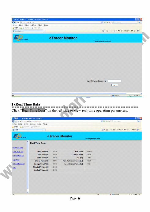
1)1)1)1) UserUserUserUser loginloginloginlogin
Not all users that are connected into Internet/Intranet can browse those data in the
system. Generally password should be input so as to ensure safety of the system.
Enter network password and press the button “log on”, and if it is right, it will display
monitoring page; otherwise, it will prompt “Password Error”.
Page 36363636
2)2)2)2) RRRRealealealeal TTTTimeimeimeime DDDDataataataata
Click “Real Time Data” on the left side to view real-time operating parameters.

Page 37373737
3)3)3)3) CtrCtrCtrCtr ParaParaParaPara SetSetSetSet
Click “Ctl Para Set” on the left side to enter Control Parameter Set page and the
system will display the current control parameter configuration. Users can also
modify control parameters. After users modify control parameters and click “submit”,
if it is successfully adjusted, “Save Success” will pop out; otherwise, “illegal para”
will appear. Click “default”, control parameters will recover to default values in line
with current system voltage.
Notes: ‘Batt Rate Voltage’ as battery rated voltage is displayed according to the real
system value, it is not changeable. If parameter modified in the period is not up to the
standard range, dialogue box “illegal para” will pop out and at the same time, the
parameter will change to the previous value.
4)4)4)4) NetNetNetNet ParaParaParaPara SetSetSetSet
Click “Net Para Set” on the left side to enter Network Parameter Set page and the
system will display the current network parameter configuration. After users modify
control parameter and click “submit”, if it is successfully adjusted, “Save Success”

Page 38383838
will pop out; otherwise, “illegal para” will appear.
5)5)5)5) LogLogLogLog QueryQueryQueryQuery
Click “Log Query” on the left side to enter Log Query page. Users can choose “Data
Log” or “Event Log”, and after click “Submit”, the system will display all current
record page by page. Users can check records by turning pages. Click “Last” to turn to
the previous page and click “Next” to turn to the next page. Users can also choose to
directly jump to any page to check records by entering page No., on “Input Page No”
and click the button of “Jump”, the page No. entered should be less than the total page
No., otherwise, it will prompt errors.

Page 39393939

Page 40404040
6)6)6)6) PasswordPasswordPasswordPassword
Click “Password” on the left side to enter password modification page. After enter the
old and new passwords, the system will judge if the old password is right and if the
new passwords entered twice is the same. If it is right, the system will present “Save
Success”, otherwise, “Password Error” will appear.
Notes: The input only supports numbers 0-9.

Page 41414141
CheckCheckCheckCheck loglogloglog datadatadatadata
eTracer only records daily data of recent 30 days and it always records standard data
as below. The space which can be used to record data will reduce with the increase of
stored data.
General data:
• Battery voltage
• Solar modules voltage
• Charging current
• Charging power
• Intraday energy generated
• Battery temperature
• Controller temperature
• SOC percentage
• Battery status
• Charging status
• Warning////Error
5555....3333 OtherOtherOtherOther IIIIntroductionsntroductionsntroductionsntroductions
1.1.1.1. CANCANCANCAN
MC1.5.3.81-4L port supports CAN bus protocol to be used to connect remote meter
or controller. The remote meter offers features as below:
• Monitor controller status
• Modify controller parameters
• Display system data on the screen
• Error or warning happens, displayed on the screen or LED indicator prompts
2.2.2.2. RSRSRSRS----232232232232
RS-232 port supports user-defined serial communication protocol to update controller
software. Controller can be connected to PC with a cross-over serial line. Users can

Page 42424242
download from our home page the latest controller program and update software to
update controller.
The way to download program file:
Turn off controller at first and make updating software on operation, which is as
follows:
① Click “Browse” and choose the program file (type is LOF). If the file is not up to
the requirements (wrong type, uncompleted or error with revision, etc), it will be
prompted via dialogue box popping out. On “File Description” bar, the basic
information on the file chosen will be displayed.
② Choose communication serial whose baud rate is 115200bps by default and click
the button “Open”.
③ Power on the controller. It will start downloading program and the progress bar
displays the percentage.
④ Restart the controller after downloading program.
Notes: In the period of procedure programming, if the power is off or disconnected, it

Page 43434343
will prompt “connect time out”.
6.06.06.06.0 Protections,Protections,Protections,Protections, TroubleshootingTroubleshootingTroubleshootingTroubleshooting &&&&MaintenanceMaintenanceMaintenanceMaintenance
6666....1111 ProtectionProtectionProtectionProtectionssss
···· PVPVPVPV SSSShorthorthorthort CCCCircuitircuitircuitircuit
If PV short circuit occurs, eTracer will stop charging. Clear it to resume normal
operation. But PV input cannot exceed 100V, otherwise it may damage the controller.
···· PVPVPVPVOvercurrentOvercurrentOvercurrentOvercurrent
If charging current is much more than rating, the controller will disconnect solar
module(s). So eTracer may not work in the maximum power point if PV current
doesn’t match with the current rating.
···· PVPVPVPVOvervoltageOvervoltageOvervoltageOvervoltage
If PV voltage is larger than maximum input open voltage 150V, PV will remain
disconnected and warn until the voltage falls safely below 145V. PV voltage cannot
be too high, otherwise it may damage the controller.
···· PVPVPVPV PolarityPolarityPolarityPolarity ReverseReverseReverseReversedddd
Fully protection against PV reverse polarity, no damage to the controller will result.
Correct the miswire to resume normal operation.
···· BatteryBatteryBatteryBattery PolarityPolarityPolarityPolarity ReverseReverseReverseReversedddd
Fully protection against battery reverse polarity, no damage to the controller will
result. Correct the miswire to resume normal operation.
···· OverheatingOverheatingOverheatingOverheating ProtectionProtectionProtectionProtection
If the temperature of the controller heat sinks exceeds 85°C, the controller will

Page 44444444
automatically start the overheating protection.
6666....2222 TroubleshootingTroubleshootingTroubleshootingTroubleshooting
� Charging LED indicator off during daytime when sunshine falls on solar
modules properly.
Probable Cause:Solar modules disconnected.
Solution:Confirm that PV and battery wire connections are correct and tight.
� Battery LED indicator red flashing, LCD displaying ‘OVD’.
Probable Cause:Battery voltage larger than over voltage disconnect voltage (OVD).
Solution:Check if battery voltage too high, and disconnect solar modules.
� Fault LED indicator flashing, LCD displaying ‘Current Err’.
Probable Cause:Charging current in three paths is unbalanced.
Solution:Disconnect solar modules and restart the eTracer; if the fault still exists,
please contact the supplier to make maintenance.
� Fault LED indicator flashing, LCD displaying ‘Over Current’.
Probable Cause:Charging current is much more than the rating.
Solution:Please check whether solar modules match with nominal parameter of the
controller. When charging current reaches 1.05~1.2 times of the rating, eTracer will
automatically adjust charging current to the rating or below but not stop; or 1.2 times
much more than nominal value, eTracer will automatically stop charging in 5 seconds.
Controller is automatically circularly activated so as to reconnect charging. Every
restarting is 60 seconds delayed, but no limit on number of times.
� Fault LED indicator flashing, LCD displaying ‘Over Temp’.

Page 45454545
Probable Cause:Heat sinks operational temperature is quite high to 85℃ or above.
Solution:The controller will automatically stop working. When the temperature below
75℃, the controller will resume to work.
� Cannot connect to the controller via RS-232.
Probable Cause:RS-232 serial baud rate setting error or serial-USB adapter incorrect
configuration.
Solution:Check the following: 1.The RS-232 cable is straight-through, not a Null
Modem (cross-over); 2.Whether the selected RS-232 serial baud rate is suited for your
device; 3.If using a serial-USB adapter, verify that the adapter software is installed
and a serial COM port has been mapped. Check the activity light on the USB adapter
if it has one. If there is no activity, the wrong COM port has been chosen or there is a
configuration issue with the adapter.

Page 46464646
6666....3333 MaintenanceMaintenanceMaintenanceMaintenance
The following inspections and maintenance tasks are recommended at least two times
per year for best controller performance.
•Check that the controller is securely mounted in a clean and dry environment.
•Check that the air flow and ventilation around the controller is not blocked. Clear all
dirt or fragments on the heat sink.
• Check all the naked wires to make sure insulation is not damaged for serious
solarization, frictional wear, dryness, insects or rats etc. Maintain or replace the
wires if necessary.
•Tighten all the terminals. Inspect for loose, broken, or burnt wire connections.
•Check and confirm that LED or LCD is consistent with required. Pay attention to any
troubleshooting or error indication .Take necessary corrective action.
•Confirm that all the system components are ground connected tightly and correctly.
• Confirm that all the terminals have no corrosion, insulation damaged, high
temperature or burnt/discolored sign, tighten terminal screws to the suggested
torque.
•Inspect for dirt, insects and corrosion, and clear up.
•Check and confirm that lightning arrester is in good condition. Replace a new one in
time to avoid damaging of the controller and even other equipments.
WarningWarningWarningWarning:RiskRiskRiskRisk ofofofof electricelectricelectricelectric shock!shock!shock!shock!
MakeMakeMakeMake suresuresuresure thatthatthatthat allallallall thethethethe powerpowerpowerpower isisisis turnedturnedturnedturned offoffoffoff beforebeforebeforebefore aboveaboveaboveabove operations,operations,operations,operations,
andandandand thenthenthenthen followfollowfollowfollow thethethethe correspondingcorrespondingcorrespondingcorresponding inspectionsinspectionsinspectionsinspections andandandand operations.operations.operations.operations.

Page 47474747
7.07.07.07.0 WarrantyWarrantyWarrantyWarranty
The eTracer charge controller is warranted to be free from defects for a period of
TWO (2) years from the date of shipment to the original end user. We will, at its
option, repair or replace any such defective products.
•••• ClaimClaimClaimClaim pppprocedurerocedurerocedurerocedure
Before requesting warranty service, check the operation manual to be certain that
there is a problem with the controller. Return the defective product to us with shipping
charges prepaid if problem cannot be solved. Provide proof of date and place of
purchase. To obtain rapid service under this warranty, the returned products must
include the model, serial number and detailed reason for the failure, the module type
and size, type of batteries and system loads. This information is critical to a rapid
disposition of your warranty claim.
•••• TTTThishishishis warrantywarrantywarrantywarranty doesdoesdoesdoes notnotnotnot applyapplyapplyapply underunderunderunder thethethethe followingfollowingfollowingfollowing conditionsconditionsconditionsconditions
1. Damage by accident, negligence, abuse or improper use.
2. PV current exceeding the ratings of product.
3. Unauthorized product modification or attempted repair.
4. Damaged occurring during shipment.
5. Damage results from acts of nature such as lightning, weather extremes.
6. Irreclaimable mechanical damage.

Page 48484848
8.08.08.08.0 SpecificationsSpecificationsSpecificationsSpecificationsElectricalElectricalElectricalElectrical
ET2415ET2415ET2415ET2415NNNN ET3415ET3415ET3415ET3415NNNN ET4415ET4415ET4415ET4415NNNN ET6415ET6415ET6415ET6415NNNN
Nominal System Voltage 12V / 24V / 36V / 48V dc
Nominal Battery Current 20A 30A 45A 60A
Maximum Solar Input Voltage 150V dc
Battery Voltage Range 8~72V dc
Maximum Input Power
12V: 260W 400W 600W 800W
24V: 520W 800W 1200W 1600W
36V: 780W 1200W 1800W 2400W
48V: 1040W 1600W 2400W 3200W
Self Consumption 1.4~2.2W
Grounding Solar or Battery Negative Terminal
Remote Temperature Sensor Port MC1.5.3.81-2L
Remote Battery Voltage Sense Port MC1.5.3.81-2L
CAN BUS Port MC1.5.3.81-4L
Ethernet Port RJ45
Serial RS-232 Port DB9, male connector
SettingsSettingsSettingsSettings
Charging Stages MPPT,Boost //// Equalize,Float
Temp. Compensation Range -25℃ ~ +55℃
Temp. Compensated Setpoints Equalize,Boost,Float,LVD

Page 49494949
Setpoingts:
Gel Acid Sealed Acid Flooded Acid
Equalize Duration Time: Gel-NO 60~180 Minutes 60~180 Minutes
Boost Duration Time: 60~180 Minutes
Over Voltage Disconnect Voltage:
Upper limit:17V ⁄⁄⁄⁄ 12V; ×2 ⁄⁄⁄⁄ 24V; ×3 ⁄⁄⁄⁄ 36V; ×4 ⁄⁄⁄⁄ 48V
Lower limit:15V ⁄⁄⁄⁄ 12V; ×2 ⁄⁄⁄⁄ 24V; ×3 ⁄⁄⁄⁄ 36V; ×4 ⁄⁄⁄⁄ 48V
Default:16V ⁄ 12V; ×2 ⁄ 24V; ×3 ⁄ 36V; ×4 ⁄ 48V
Charging Limit Voltage:
Upper limit:16V ⁄⁄⁄⁄ 12V; ×2 ⁄⁄⁄⁄ 24V; ×3 ⁄⁄⁄⁄ 36V; ×4 ⁄⁄⁄⁄ 48V
Lower limit:14V ⁄⁄⁄⁄ 12V; ×2 ⁄⁄⁄⁄ 24V; ×3 ⁄⁄⁄⁄ 36V; ×4 ⁄⁄⁄⁄ 48V
Default:15.5V ⁄ 12V; ×2 ⁄ 24V; ×3 ⁄ 36V; ×4 ⁄ 48V
Over Voltage Reconnect Voltage:
Upper limit:16V ⁄⁄⁄⁄ 12V; ×2 ⁄⁄⁄⁄ 24V; ×3 ⁄⁄⁄⁄ 36V; ×4 ⁄⁄⁄⁄ 48V
Lower limit:14V ⁄⁄⁄⁄ 12V; ×2 ⁄⁄⁄⁄ 24V; ×3 ⁄⁄⁄⁄ 36V; ×4 ⁄⁄⁄⁄ 48V
Default:15V ⁄⁄⁄⁄ 12V; ×2 ⁄⁄⁄⁄ 24V; ×3 ⁄⁄⁄⁄ 36V; ×4 ⁄⁄⁄⁄ 48V
Equalize Charging Voltage:
Gel-NO Upper limit:15.2V ⁄⁄⁄⁄ 12V; ×2 ⁄⁄⁄⁄ 24V; ×3 ⁄⁄⁄⁄ 36V; ×4 ⁄⁄⁄⁄ 48V
Gel-NO Lower limit:14.2V ⁄⁄⁄⁄ 12V; ×2 ⁄⁄⁄⁄ 24V; ×3 ⁄⁄⁄⁄ 36V; ×4 ⁄⁄⁄⁄ 48V
Gel-NO Default: Default:
14.6V ⁄⁄⁄⁄ 12V; ×2 ⁄⁄⁄⁄ 24V; 14.8V ⁄⁄⁄⁄ 12V; ×2 ⁄⁄⁄⁄ 24V;
×3 ⁄⁄⁄⁄ 36V; ×4 ⁄⁄⁄⁄ 48V ×3 ⁄⁄⁄⁄ 36V; ×4 ⁄⁄⁄⁄ 48V
Boost Charging Voltage:
Upper limit:15V ⁄⁄⁄⁄ 12V; ×2 ⁄⁄⁄⁄ 24V; ×3 ⁄⁄⁄⁄ 36V; ×4 ⁄⁄⁄⁄ 48V
Lower limit:13.8V ⁄⁄⁄⁄ 12V; ×2 ⁄⁄⁄⁄ 24V; ×3 ⁄⁄⁄⁄ 36V; ×4 ⁄⁄⁄⁄ 48V
Default: Default: Default:
14.2V ⁄⁄⁄⁄ 12V; ×2 ⁄⁄⁄⁄ 24V; 14.4V ⁄⁄⁄⁄ 12V; ×2 ⁄⁄⁄⁄ 24V; 14.6V ⁄⁄⁄⁄ 12V; ×2 ⁄⁄⁄⁄ 24V;

Page 50505050
×3 ⁄⁄⁄⁄ 36V; ×4 ⁄⁄⁄⁄ 48V ×3 ⁄⁄⁄⁄ 36V; ×4 ⁄⁄⁄⁄ 48V ×3 ⁄⁄⁄⁄ 36V; ×4 ⁄⁄⁄⁄ 48V
Float Charging Voltage:
Upper limit:14.2V ⁄⁄⁄⁄ 12V; ×2 ⁄⁄⁄⁄ 24V; ×3 ⁄⁄⁄⁄ 36V; ×4 ⁄⁄⁄⁄ 48V
Lower limit:13.2V ⁄⁄⁄⁄ 12V; ×2 ⁄⁄⁄⁄ 24V; ×3 ⁄⁄⁄⁄ 36V; ×4 ⁄⁄⁄⁄ 48V
Default:13.8V ⁄⁄⁄⁄ 12V; ×2 ⁄⁄⁄⁄ 24V; ×3 ⁄⁄⁄⁄ 36V; ×4 ⁄⁄⁄⁄ 48V
Boost Reconnect Charging Voltage:
Upper limit:13.5V ⁄⁄⁄⁄ 12V; ×2 ⁄⁄⁄⁄ 24V; ×3 ⁄⁄⁄⁄ 36V; ×4 ⁄⁄⁄⁄ 48V
Lower limit:12.7V ⁄⁄⁄⁄ 12V; ×2 ⁄⁄⁄⁄ 24V; ×3 ⁄⁄⁄⁄ 36V; ×4 ⁄⁄⁄⁄ 48V
Default:13.2V ⁄⁄⁄⁄ 12V; ×2 ⁄⁄⁄⁄ 24V; ×3 ⁄⁄⁄⁄ 36V; ×4 ⁄⁄⁄⁄ 48V
Low Voltage Reconnect Voltage:
Upper limit:13.2V ⁄⁄⁄⁄ 12V; ×2 ⁄⁄⁄⁄ 24V; ×3 ⁄⁄⁄⁄ 36V; ×4 ⁄⁄⁄⁄ 48V
Lower limit:12V ⁄⁄⁄⁄ 12V; ×2 ⁄⁄⁄⁄ 24V; ×3 ⁄⁄⁄⁄ 36V; ×4 ⁄⁄⁄⁄ 48V
Default:12.6V ⁄⁄⁄⁄ 12V; ×2 ⁄⁄⁄⁄ 24V; ×3 ⁄⁄⁄⁄ 36V; ×4 ⁄⁄⁄⁄ 48V
Under Voltage Warning Reconnect Voltage:
Upper limit:12.6V ⁄⁄⁄⁄ 12V; ×2 ⁄⁄⁄⁄ 24V; ×3 ⁄⁄⁄⁄ 36V; ×4 ⁄⁄⁄⁄ 48V
Lower limit:11.8V ⁄⁄⁄⁄ 12V; ×2 ⁄⁄⁄⁄ 24V; ×3 ⁄⁄⁄⁄ 36V; ×4 ⁄⁄⁄⁄ 48V
Default:12.2V ⁄⁄⁄⁄ 12V; ×2 ⁄⁄⁄⁄ 24V; ×3 ⁄⁄⁄⁄ 36V; ×4 ⁄⁄⁄⁄ 48V
Under Voltage Warning Voltage:
Upper limit:12.4V ⁄⁄⁄⁄ 12V; ×2 ⁄⁄⁄⁄ 24V; ×3 ⁄⁄⁄⁄ 36V; ×4 ⁄⁄⁄⁄ 48V
Lower limit:11.6V ⁄⁄⁄⁄ 12V; ×2 ⁄⁄⁄⁄ 24V; ×3 ⁄⁄⁄⁄ 36V; ×4 ⁄⁄⁄⁄ 48V
Default:12V ⁄⁄⁄⁄ 12V; ×2 ⁄⁄⁄⁄ 24V; ×3 ⁄⁄⁄⁄ 36V; ×4 ⁄⁄⁄⁄ 48V
Low Voltage Disconnect Voltage:
Upper limit:11.8V ⁄⁄⁄⁄ 12V; ×2 ⁄⁄⁄⁄ 24V; ×3 ⁄⁄⁄⁄ 36V; ×4 ⁄⁄⁄⁄ 48V
Lower limit:10.5V ⁄⁄⁄⁄ 12V; ×2 ⁄⁄⁄⁄ 24V; ×3 ⁄⁄⁄⁄ 36V; ×4 ⁄⁄⁄⁄ 48V
Default:11.1V ⁄⁄⁄⁄ 12V; ×2 ⁄⁄⁄⁄ 24V; ×3 ⁄⁄⁄⁄ 36V; ×4 ⁄⁄⁄⁄ 48V
Discharging Limit Voltage:
Upper limit:11V ⁄⁄⁄⁄ 12V; ×2 ⁄⁄⁄⁄ 24V; ×3 ⁄⁄⁄⁄ 36V; ×4 ⁄⁄⁄⁄ 48V
Lower limit:10.5V ⁄⁄⁄⁄ 12V; ×2 ⁄⁄⁄⁄ 24V; ×3 ⁄⁄⁄⁄ 36V; ×4 ⁄⁄⁄⁄ 48V

Page 51515151
Default:10.8V ⁄⁄⁄⁄ 12V; ×2 ⁄⁄⁄⁄ 24V; ×3 ⁄⁄⁄⁄ 36V; ×4 ⁄⁄⁄⁄ 48V
Temperature Compensation Coefficient:
(TEMPCO)*
Upper limit: -9mV / ℃ / cell (25℃ ref.)
Lower limit: -0mV / ℃ / cell (25℃ ref.)
Default: -5mV /℃ / cell (25℃ ref.)
MMMMechanicalechanicalechanicalechanicalET2415ET2415ET2415ET2415NNNN ET3415ET3415ET3415ET3415NNNN ET4415ET4415ET4415ET4415NNNN ET6415ET6415ET6415ET6415NNNN
Overall:
Length: 206mm 231mm 285mm 285mm
width: 203mm 203mm 203mm 203mm
height: 105mm 105mm 105mm 121mm
Mounting:
Length: 150mm 150mm 200mm 200mm
width: 193mm 193mm 193mm 193mm
Net Weight: 2.6kg 4.1kg 4.4kg 5.0kg
Terminal: 35mm2 35mm2 35mm2 35mm2
Mounting hole: Φ10(M8)
EnvironmentEnvironmentEnvironmentEnvironmentalalalal
Ambient Temp. Range -25℃ ~ +55℃
Storage Temp. Range -30℃ ~ +85℃
Humidity range 10 ~ 90% N.C.
Altitude Range ≤3000 m
Enclosure IP20
ProtectionProtectionProtectionProtectionCharging over current disconnect
Charging over current reconnect
Solar short circuit disconnect

Page 52525252
Solar short circuit reconnect
Solar polarity reversed protect
Battery polarity reversed protect
Battery high voltage disconnect
Battery high voltage reconnect
High temperature disconnect
High temperature reconnect
PV Power — Conversion Efficiency CurvesIIIIlluminationlluminationlluminationllumination IIIIntensityntensityntensityntensity:::: 1000W/m1000W/m1000W/m1000W/m2222 Temperature:Temperature:Temperature:Temperature: 25252525℃
Test model: ET2415N
1. Solar MPP Voltage(17V、34V、68V、100V) //// System Voltage(12V)
2. Solar MPP Voltage(34V、68V、100V) //// System Voltage(24V)
Power
Efficiency 17V
68V 100V
Efficiency
34V
34V

Page 53535353
3. Solar MPP Voltage(68V、100V) //// System Voltage(36V)
4. Solar MPP Voltage(68V、100V) //// System Voltage(48V)
68V 100V
Power
68V100V
68V
100V
Efficiency
Efficiency
Power
Power

Page 54545454
Page 53
ET2415 Dimensions(mm)

Page 54

Page 55
ET3415 Dimensions(mm)

Page 56

Page 57
ET4415 Dimensions(mm)

Page 58

Page 59
ET6415 Dimensions(mm)

Page 60