solar eclipse manual eclipse-man… · solar eclipse manual keep this manual in a safe place!...
TRANSCRIPT
Solar Eclipse Manual
KEEP THIS MANUAL IN A SAFE PLACE!
IMPORTANT SAFETY INFORMATION INSIDE!
REV. no. 12 made on 10/04/2017
P800SRL
Via Valdilocchi, 6/F
19126 La Spezia
VAT n. 01353280116
This manual contains important safety instructions that must be followed during installation and start-
up of the device. It is advisable to pay particular attention to the installation instructions in order to
reduce the risk of electrical shock and to prevent damage to the device.
This document contains information of P800 SRL properties. The content of this document, or any part
thereof should not be reproduced or communicated to any third party without the express written
consent of P800 SRL.
Any changes / modifications not approved by the party responsible could void the user's authority to
USE the equipment
Index
1 GENERAL INFORMATIONS ...................................................................................... 6
1.4 Warranty 7
1.5 Quality 8
1.6 Responsibility 8
1.7 Safety information 8
1.8 Type label and symbols explanation 10
2 GUIDELINES AND SAFETY MEASURES ................................................................... 12
2.1 Symbols and warnings 12
2.2 Specific requirement 12
2.3 Before installing 13
2.4 Safety and installation guidelines 13
2.5 Batteries use warning 13
3 INSTALLATION ..................................................................................................... 14
3.1 Unpacking 14
3.2 Environment 14
3.3 Solar Eclipse fixing 15
3.4 Solar Eclipse board wiring 15
3.5 Grid-tied sensor installation and wiring 20
4 SOLAR ECLIPSE CONFIGURATION ......................................................................... 21
4.1 Installing software for the installer 23
4.2 Advance configuration operating parameters 24
4.3 Configuration with "free" parameters 25
4.4 Solar Eclipse reboot procedure 26
4.5 Solar Eclipse reset procedure 26
4.6 Notes on the battery pack sizing 27
4.7 Warnings and tips for the formation of the battery pack 48 V 30
4.8 Warnings and parameters to be set on the grid inverter 30
4.9 Inverter Power One / ABB 31
4.10 Inverter SMA 31
4.11 Inverter FRONIUS 31
5 START-UP ............................................................................................................. 32
3
5.1 Stopping the Solar Eclipse 33
5.2 Operation Modes 33
5.3 Battery Charger Mode 33
5.4 Night Mode delivery 34
5.5 Power mode 34
5.6 Battery charger maintenance Mode 34
5.7 Battery pack “full charge” mode 35
5.8 Power-up and Power-off 35
5.9 Indicator lights 35
5.10 Remote monitoring via Ethernet network jack 37
5.11 Fault search 38
5.12 Maintenance 40
6 TECHNICAL FEATURES .......................................................................................... 41
6.1 Default parameters 42
6.2 Modules with a number of cells other than 60 43
4
Figures index
Figure 1 - Solar Eclipse ............................................................................................................................... 6 Figure 2 - Label and certifications ............................................................................................................. 10 Figure 3 - Included accessories ................................................................................................................. 14 Figure 4 - Twisted-pair cable for Power Meter and house load sensors (Monitoring Kit) ............................ 16 Figure 5 - Power Meter and house load sensor connectors wiring ............................................................. 17 Figure 6 - Power wiring scheme ............................................................................................................... 18 Figure 7 - Solar Eclipse wiring board ......................................................................................................... 19 Figure 8 - Electrical panel wiring scheme .................................................................................................. 20 Figure 9 - Wiring grid Power Meter .......................................................................................................... 21 Figure 10 - Configuration dip-switches .................................................................................................... 21 Figure 11 - Battery configuration through dip-switches............................................................................. 22 Figure 12 - Configuration Software – Trend tab ........................................................................................ 23 Figure 13 - Configuration software – Parameters tab ................................................................................ 24 Figure 14 - Scheme order closing / opening switches start / stop .............................................................. 32 Figure 15 - lights – Front LED’s ................................................................................................................. 36 Figure 16 - Ethernet port e Supply Fuse .................................................................................................... 36 Figure 17 – Installer monitoring portal ..................................................................................................... 37 Figure 18 - Solar Eclipse configuration with browser ................................................................................. 38

5
Tables Index
Table 1 – Label symbols meaning ............................................................................................................. 11 Table 2 – Battery pack cables size ............................................................................................................ 15 Table 3 – Number of batteries depending of the nominal voltage ............................................................. 27 Table 4 – Energy reserve classes for 48V batteries .................................................................................... 28 Table 5 – Battery dimensioning depending on the loads and PV plant power ............................................ 29 Table 6 – Solar Eclipse datasheet ............................................................................................................. 41 Table 7 – Default parameters for generic batteries ................................................................................... 42 Table 8 – PV modules conversion table .................................................................................................... 43
6
1 GENERAL INFORMATIONS
1.1 About Solar Eclipse
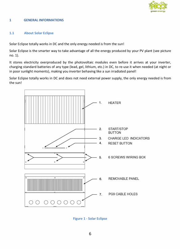
Solar Eclipse totally works in DC and the only energy needed is from the sun!
Solar Eclipse is the smarter way to take advantage of all the energy produced by your PV plant (see picture no. 1).
It stores electricity overproduced by the photovoltaic modules even before it arrives at your inverter, charging standard batteries of any type (lead, gel, lithium, etc.) in DC, to re-use it when needed (at night or in poor sunlight moments), making you inverter behaving like a sun irradiated panel!
Solar Eclipse totally works in DC and does not need external power supply, the only energy needed is from the sun!
Figure 1 - Solar Eclipse
7
1.2 How the Solar Eclipse works
When the PV modules power exceeds the power required by the loads of the house, Solar Eclipse feels, through the network sensor, that there is an electricity grid connection and begins to store energy into the connected batteries. On the contrary, when the power required by the loads of the house is higher than the one produced by the PV modules (for example if it is cloudy or at night), Solar Eclipse picks the energy stored by the batteries up and provides it via the inverter. Solar Eclipse works as a battery charger when the solar power is in excess, and as a solar module string irradiated from the sun when the solar power is not sufficient or it is totally absent. This allows the inverter to deliver only the power required, minimizing unnecessary entries or withdrawals from the grid. Solar Eclipse complies with the following rules: • No batteries charge through grid energy • The available energy from the PV modules is used to power utilities • The excess energy is used to charge the batteries • The further energy produced by the plant is sold to grid network. • Battery power used only if the sun is not enough to power utilities, or at night 1.3 Manual use
WARNING: the manual is a guideline for a safe and effective use as well as for the maintenance
and possible correction of minor Solar Eclipse malfunctions. It is therefore essential that the
person who uses or carries interventions on has acquired a complete familiarity with the contents
of this manual, and will closely follow the instructions.
WARNING: Solar Eclipse installation and maintenance must be carried on by qualified, trained
and authorized personnel only, compliant with the local regulations and applying the guidelines
and the safety measures. Keep the manual in a safe place.
1.4 Warranty
• The activation of this warranty is absolutely subject to the registration of the product within 30 days of its
installation, on the computer portal available on the website www.solareclipse.it as indicated on the
installer card inserted in the box. Computer registration will be faithful to any dispute and dispute, and is
an integral part of the warranty itself.
In the absence of such registration, the guarantee will not be valid without exception.

8
• P800 SRL guarantees that this product is manufactured in accordance with the law. Maintenance not compliant with the guidelines, the instructions and the specifications contained in the user's manual, may cause damages. This could result in voiding the warranty.
• The warranty covers repairing cost and / or replacement of the product. Defective parts shipping cost and labour costs are not covered by this warranty.
• The warranty does not cover any damage to the batteries in any case, especially if the set parameters do not match those specified by the manufacturer.
• The proper operation of Solar Eclipse is guaranteed only with a minimum daily radiation power of
at least 100 W.
• All verification, updating, repair and replacement operations will be carried out by qualified p800srl personnel exclusively in p800srl laboratories, no work on works or works on private or corporate clients will be provided.
1.5 Quality
All our products are tested and inspected during production and before delivery. The standard warranty period is 24 months from the date of purchase.
1.6 Responsibility
P800 SRL disclaims any liability in the following cases:
• consequential damages related to the use of Solar Eclipse • possible manual errors and the consequences thereof • damage caused by improper use of Solar Eclipse • damage caused by the battery pack and its connections
1.7 Safety information
WARNING: All the following operations must be carried out by qualified personnel only in compliance with national and local security regulations.
WARNING: During the installation, you must follow manual instructions and warnings step-by-
step in order to avoid danger to the operator and damaging the equipment. Operations that are not complying with the instructions will result in immediate warranty lapse.
WARNING: Some device parts can be live, non-insulated or have hot surfaces. Unauthorized
removal of the necessary protections, improper use, incorrect installation or incorrect operation,
9
the unit tampering (for example opening additional holes), can cause serious damage to persons or things and leads to the immediate warranty voiding.
WARNING: to avoid the system damage and / or malfunction, please insert a standard fuse between the Solar Eclipse and the battery pack 32A as shown in the wiring diagram (see Figure 16).
CAUTION: The Solar Eclipse is INSULATION TRANSFORMERLESS. An inverter with insulation transformer is needed or, in case of inverter also without insulation transformer, it is necessary to maintain the battery pack floating: no pole must be connected to earth, also TERMINALS OF BATTERIES MUST BE PROTECTED WITH A DOUBLE INSULATION as they are located at the same potential of the grid IT CAN CAUSE BODILY HARM OR ELECTRIC SHOCK!!!
WARNING: PV plant design with Solar Eclipse must always respect the nominal ratings of voltage and current phase.
CAUTION !!!: Always install the battery pack in a room equipped with air intake, and not used as
residential.
WARNING !!!: In case of liquid electrolyte batteries use, please put the battery pack in a widely
ventilated room, separated from the one in which other electrical devices such as inverters,
panels and Solar Eclipse are!!! The use of liquid electrolyte batteries can cause highly explosive
vapors !!!
10
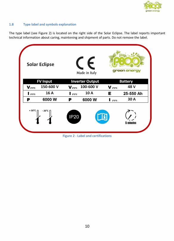
1.8 Type label and symbols explanation The type label (see Figure 2) is located on the right side of the Solar Eclipse. The label reports important technical information about caring, maintening and shipment of parts. Do not remove the label.
Figure 2 - Label and certifications
11
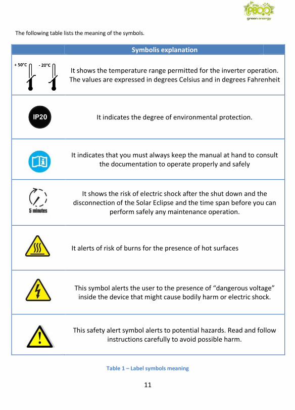
The following table lists the meaning of the symbols.
Symbolis explanation
It shows the temperature range permitted for the inverter operation. The values are expressed in degrees Celsius and in degrees Fahrenheit
It indicates the degree of environmental protection.
It indicates that you must always keep the manual at hand to consult the documentation to operate properly and safely
It shows the risk of electric shock after the shut down and the disconnection of the Solar Eclipse and the time span before you can
perform safely any maintenance operation.
It alerts of risk of burns for the presence of hot surfaces
This symbol alerts the user to the presence of “dangerous voltage” inside the device that might cause bodily harm or electric shock.
This safety alert symbol alerts to potential hazards. Read and follow instructions carefully to avoid possible harm.
Table 1 – Label symbols meaning

12
2 GUIDELINES AND SAFETY MEASURES
2.1 Symbols and warnings
The following symbols are used throughout the manual to highlight important information:
CAUTION: indicates a hazardous situation which, if not avoided, could result in
minor or moderate injury.
WARNING: indicates a hazardous situation which, if not avoided, could result in
death or serious injury..
2.2 Specific requirements
1 Solar Eclipse is manufactured in accordance with safety and technical requirements
2 Solar Eclipse is to be used under the following conditions only: • To charge lead acid, gel, nickel, lithium-ion batteries and to provide power to grid
connected inverter. • To convert the string voltage of the power supply modules for charging batteries.
• Connected to a battery pack with all the safety systems required for the accumulation of chemical systems with nominal voltage of 48 V.
• In appropriate technical conditions.
• In an enclosed space, well ventilated, protected from rain, condensation, moisture and dust.
• In compliance with the instructions in the manual.
CAUTION: set the parameters characteristic of the charge and discharge cycle of the battery
pack as recommended by the battery manufacturer. Refer to the installer software available in
the download area of website www.solareclipse.it download area.
WARNING: a misuse/improper use of the charge and discharge cycle can cause damage and / or
battery explosion.
WARNING: Do not use the Solar Eclipse in situations where there is a risk of gas or dust
explosions or in presence of potentially flammable products.
Any use of the product other than described in the Intended Use section does not
qualify as appropriate. P800 SRL is not responsible for any damage that may ensue.

13
2.3 Before installing
Users must always:
• Follow this manual during installation and maintenance. Before installing or using the product, read all of the instructions, cautions, and warnings in this manual.
• Be familiar with the contents of this manual. This applies particularly to Chapter "guidelines and directives for safety."
2.4 Safety and installation guidelines
• Protect your Solar Eclipse from rain, snow, spray, moisture, excessive soiling and condensation
situations. In order to reduce the risk of fire, do not cover or obstruct the ventilation holes. Do not
install the Solar Eclipse in a room without ventilation because it could overheat.
• In case of fire, you must use a fire extinguisher suitable for electrical equipment.
• Short-circuiting the device or reversing the polarity will cause serious damage to batteries, Solar
Eclipse and wiring. The fuses are located between the batteries and the Solar Eclipse are not able to
avoid the damage caused by the reversal of the polarity, damage that will void the warranty.
• Protect the DC wiring with a fuse according to the guidelines of this manual.
• Connection and protection must be carried out in accordance with local regulations.
• Do not work on Solar Eclipse nor on the system if they are still connected to a power source. Allow
only qualified electricians to carry out modifications to the electrical system.
• Check the wiring and connections at least once a year. Defects such as loose connections, burnt
wiring etc. must be corrected immediately.
• Do not touch the equipment if wet or if you have sticky hands.
• Make sure that the product is mounted properly and safely and always use appropriate transport
equipment.
• The opening of the service door is the sole responsibility of qualified and licensed
2.5 Batteries use warning
• Remember that despite the battery pack voltage is 48 V, when the Solar Eclipse is connected to an
insulation transformerless inverter, the battery pack has the same voltage of the power grid and it
is potentially dangerous for the human body!
• In the case of liquid electrolyte batteries it is necessary to place the batteries in a well ventilated
room and not used for residential.
• Do not short circuit the batteries as this could cause an explosion and fire risk.
• Over-discharge of the batteries and / or high charging voltages can cause serious damage to the
batteries. Do not discharge / charge batteries beyond the limits recommended by the
manufacturer.
• The installation of the batteries and the Solar Eclipse adjustments are the sole responsibility of
authorized personnel.
14
3 INSTALLATION
During installation and start up of Solar Eclipse, always refer to the guidelines and the safety instruction. See Chapter 2 of this manual.
3.1 Unpacking
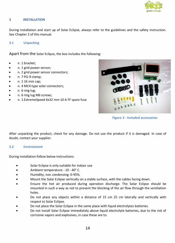
Apart from the Solar Eclipse, the box includes the following:
• n. 1 bracket;
• n. 1 grid power sensor; • n. 2 grid power sensor connectors;
• n. 7 PG-9 clamp;
• n. 1 16 mm cap;
• n. 4 MC4 type solar connectors; • n. 6 ring lug;
• n. 6 ring lug M6 screws;
• n. 1 ExtremeSpeed 6x32 mm 10 A FF spare fuse
Figure 3 – Accessories included
After unpacking the product, check for any damage. Do not use the product if it is damaged. In case of doubt, contact your supplier. 3.2 Environment
During installation follow below instructions:
• Solar Eclipse is only suitable for indoor use • Ambient temperature: -10 - 40° C.
• Humidity, non condensing: 0-95%.
• Mount the Solar Eclipse vertically on a stable surface, with the cables facing down.
• Ensure the hot air produced during operation discharge. The Solar Eclipse should be mounted in such a way as not to prevent the blocking of the air flow through the ventilation holes.
• Do not place any objects within a distance of 15 cm 25 cm laterally and vertically with respect to Solar Eclipse.
• Do not place the Solar Eclipse in the same place with liquid electrolytes batteries.
• Do not install Solar Eclipse immediately above liquid electrolyte batteries, due to the risk of corrosive vapors and explosives, in case these are to.
Figure 3 - Included accessories
15
3.3 Solar Eclipse fixing
To fix the Solar Eclipse, follow below instruction: 1 Mark the two points for fixing the bracket on the wall using the two holes of the bracket itself,
taking into account the overall dimensions and the space needed for ventilation. 2 Drill holes and secure the bracket with M6 bolts. 3 Hook Solar Eclipse through the back hook to the bracket on the wall.
3.4 Solar Eclipse board wiring
CAUTION: Before removing the service door make sure you have disconnected Solar Eclipse for at least 5 minutes to allow the internal parts to discharge to avoid risk of electrocution.
Before starting the wiring make sure that: • The PV modules are disconnetted from the inverter • The inverter is electricity grid insulated • The Solar Eclipse is insulated in relation to the inverter • The battery pack is disconnetted Proceed with the wiring as follows:
• Remove the service door (6) unscrewing the screws (5) see Figure 1
• Prepare the cables to connect to the inverter and the modules with lugs eyelet on one side and
MC4 solar connectors supplied on the other, remembering to insert the PG9
• Prepare the battery pack cables (solar photovoltaic double insulation cables can be used) with
ring terminals using a minimum section 4 mm cable remembering to insert the PG9.
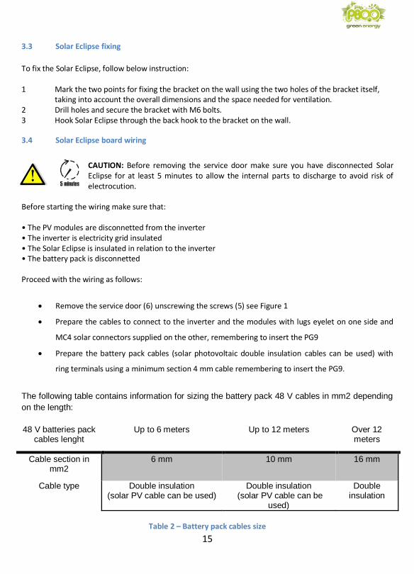
The following table contains information for sizing the battery pack 48 V cables in mm2 depending
on the length:
48 V batteries pack cables lenght
Up to 6 meters Up to 12 meters Over 12 meters
Cable section in mm2
6 mm 10 mm 16 mm
Cable type Double insulation (solar PV cable can be used)
Double insulation (solar PV cable can be
used)
Double insulation
Table 2 – Battery pack cables size

16
NOTE: To prevent electromagnetic disturbances generated by power cables from generating
"bounced" voltage, current and frequency readings of the Power Meter, always wrap the
signal cables on dedicated cavities and appropriately separate, trying to avoid wiring lengths
greater than 100 meters.
NOTE: In the presence of electromagnetic disturbance, the voltage and frequency values
detected by the Power Meter could be "bumped" and this could cause the Solar Eclipse
"block" status, which detects network parameters outside the admitted range.
• Prepare the grid sensor wire with a three-pole
terminal using an UTP twisted pair cable or a shielded STP twisted-pair cable with a minimum 0.25 mm square section (see image below).
WARNING: If the inverter has no isolating transformer, double insulated signal cables (double sheath in polyethylene) should be used and do not ground any screen stocking.
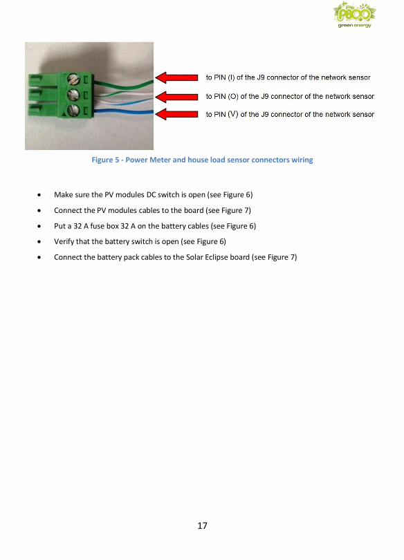
• Use two pairs of twisted wires, making sure to connect the central PIN (O) to both pairs as shown in figure 4. In the case of STP shielded cable, connect the braid to the central PIN (O), remembering to insert the PG9 and note the color of the wires.
Figure 4 - Twisted-pair cable for Power Meter and house load sensors (Monitoring Kit)
17
Figure 5 - Power Meter and house load sensor connectors wiring
• Make sure the PV modules DC switch is open (see Figure 6)
• Connect the PV modules cables to the board (see Figure 7)
• Put a 32 A fuse box 32 A on the battery cables (see Figure 6)
• Verify that the battery switch is open (see Figure 6)
• Connect the battery pack cables to the Solar Eclipse board (see Figure 7)
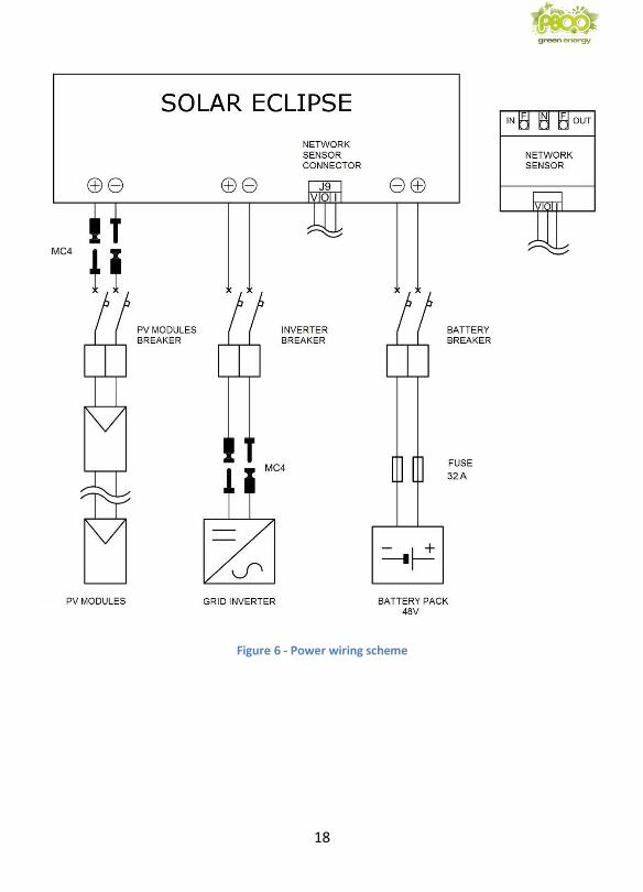
18
Figure 6 - Power wiring scheme
19
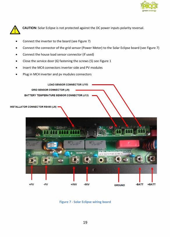
CAUTION: Solar Eclipse is not protected against the DC power inputs polarity reversal.
• Connect the inverter to the board (see Figure 7)
• Connect the connector of the grid sensor (Power Meter) to the Solar Eclipse board (see Figure 7)
• Connect the house load sensor connector (if used)
• Close the service door (6) fastening the screws (5) see Figure 1
• Insert the MC4 connectors inverter side and PV modules
• Plug in MC4 inverter and pv mudules connectors
Figure 7 - Solar Eclipse wiring board
20
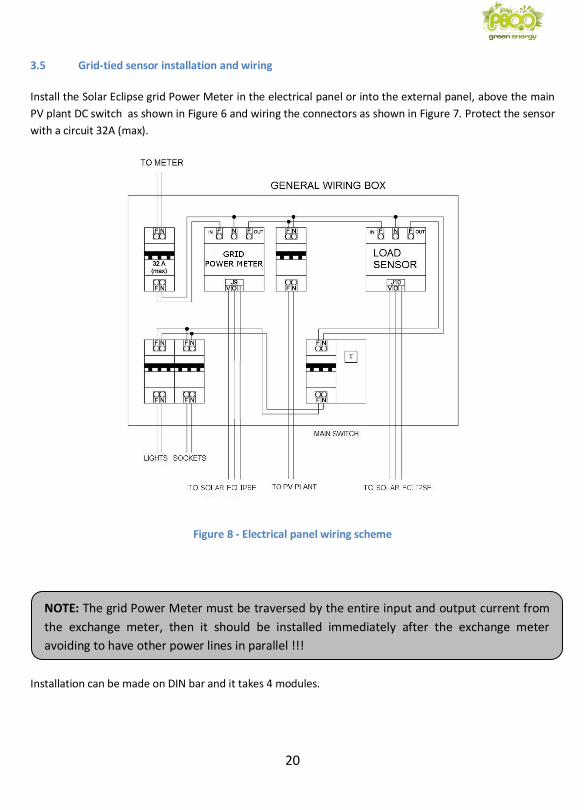
NOTE: The grid Power Meter must be traversed by the entire input and output current from
the exchange meter, then it should be installed immediately after the exchange meter
avoiding to have other power lines in parallel !!!
3.5 Grid-tied sensor installation and wiring
Install the Solar Eclipse grid Power Meter in the electrical panel or into the external panel, above the main
PV plant DC switch as shown in Figure 6 and wiring the connectors as shown in Figure 7. Protect the sensor
with a circuit 32A (max).
Figure 8 - Electrical panel wiring scheme
Installation can be made on DIN bar and it takes 4 modules.
21
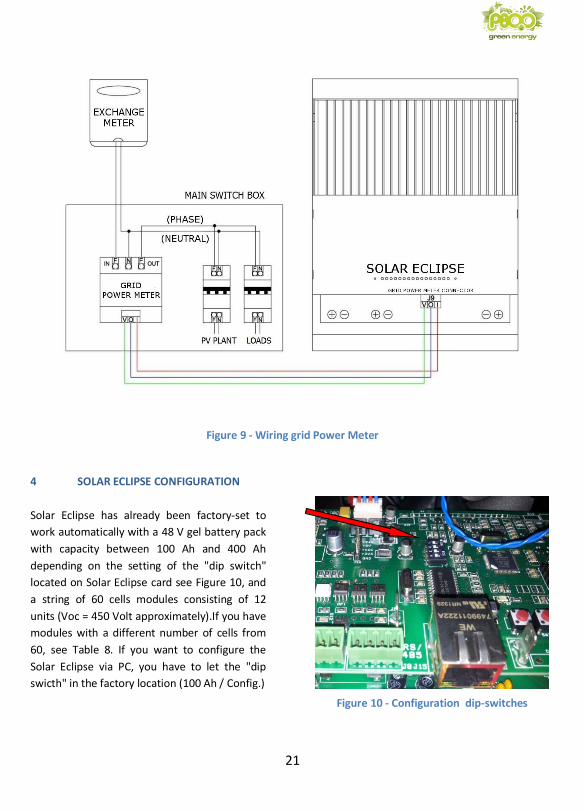
Figure 9 - Wiring grid Power Meter
4 SOLAR ECLIPSE CONFIGURATION
Solar Eclipse has already been factory-set to
work automatically with a 48 V gel battery pack
with capacity between 100 Ah and 400 Ah
depending on the setting of the "dip switch"
located on Solar Eclipse card see Figure 10, and
a string of 60 cells modules consisting of 12
units (Voc = 450 Volt approximately).If you have
modules with a different number of cells from
60, see Table 8. If you want to configure the
Solar Eclipse via PC, you have to let the "dip
swicth" in the factory location (100 Ah / Config.)
Figure 10 - Configuration dip-switches
22
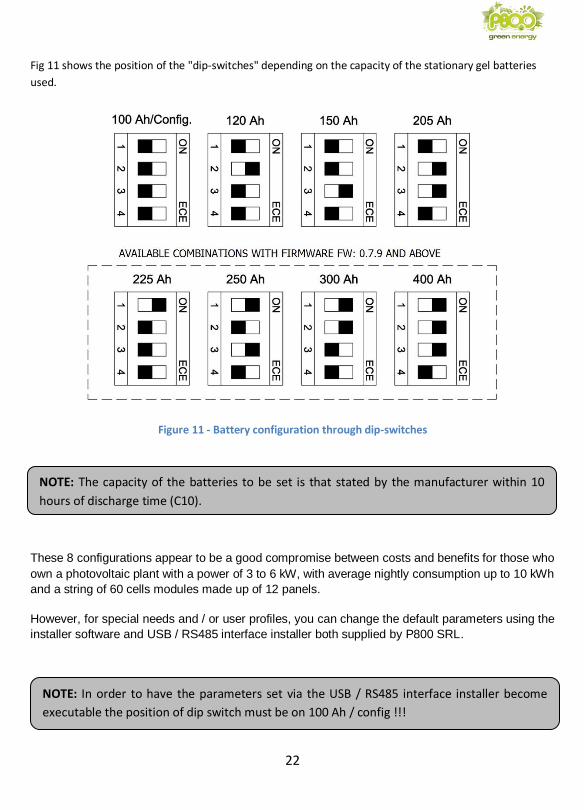
NOTE: The capacity of the batteries to be set is that stated by the manufacturer within 10
hours of discharge time (C10).
Fig 11 shows the position of the "dip-switches" depending on the capacity of the stationary gel batteries
used.
Figure 11 - Battery configuration through dip-switches
These 8 configurations appear to be a good compromise between costs and benefits for those who
own a photovoltaic plant with a power of 3 to 6 kW, with average nightly consumption up to 10 kWh
and a string of 60 cells modules made up of 12 panels.
However, for special needs and / or user profiles, you can change the default parameters using the
installer software and USB / RS485 interface installer both supplied by P800 SRL.
NOTE: In order to have the parameters set via the USB / RS485 interface installer become
executable the position of dip switch must be on 100 Ah / config !!!
23
4.1 Installing software for the installer
In the case the string of modules is different from 12 modules or the batteries are not standard it is
necessary to configure Solar Eclipse using the installer software. In any case, for a professional installation
of the equipment and for maximum performance and reliability of the system it is recommended to always
use the configuration via PC.
On www.solareclipse.it/en/download you can download the software and system libraries needed to run
the Solar Eclipse configurator, the use is reserved to authorized installers only. To install the software,
proceed as follows:
• Goto www.solareclipse.it/en/download
• Download the zip file “Solar Eclipse Configurator”
• Unzip it and save all files in a folder in your PC
• Run the exe file you will find in the folder
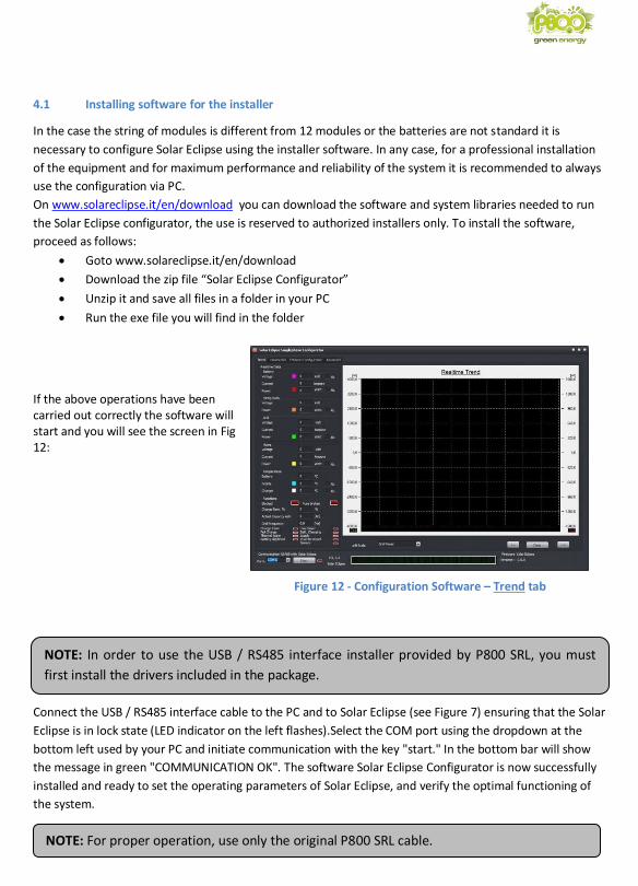
If the above operations have been carried out correctly the software will start and you will see the screen in Fig 12:
Connect the USB / RS485 interface cable to the PC and to Solar Eclipse (see Figure 7) ensuring that the Solar
Eclipse is in lock state (LED indicator on the left flashes).Select the COM port using the dropdown at the
bottom left used by your PC and initiate communication with the key "start." In the bottom bar will show
the message in green "COMMUNICATION OK". The software Solar Eclipse Configurator is now successfully
installed and ready to set the operating parameters of Solar Eclipse, and verify the optimal functioning of
the system.
NOTE: In order to use the USB / RS485 interface installer provided by P800 SRL, you must
first install the drivers included in the package.
NOTE: For proper operation, use only the original P800 SRL cable.
Figure 12 - Configuration Software – Trend tab
24
4.2 Advance configuration operating parameters
Proceed with the connection of Solar Eclipse as follows:
• Connect the RS485 socket on your PC (where you installed the software installer see section 4.1
through the appropriate interface
• Close the battery switch and switch-on the Solar Eclipse
• Select via the drop down on the bottom left the COM port used by your PC and initiate communication via the button "start". In the bottom bar will show the message in green "COMMUNICATION OK".
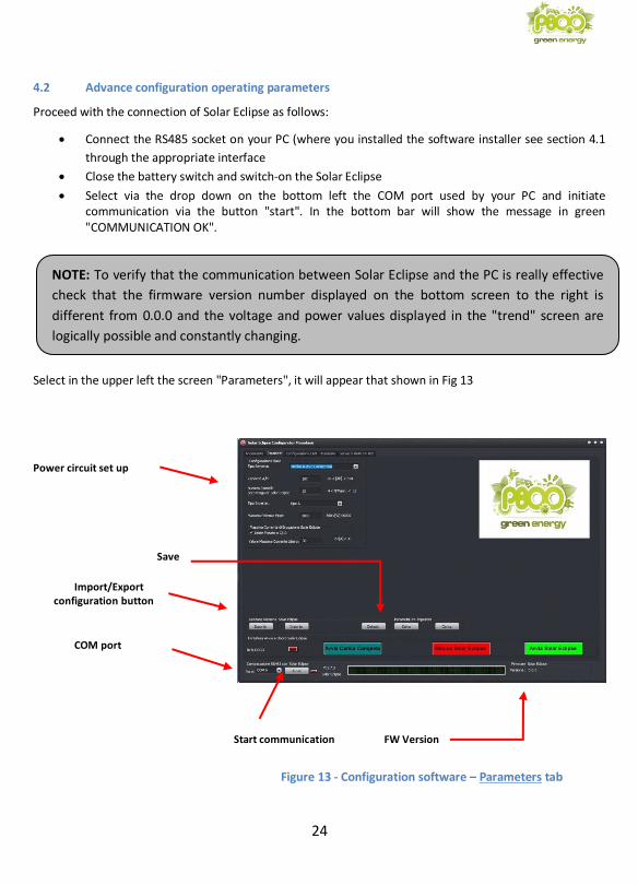
Select in the upper left the screen "Parameters", it will appear that shown in Fig 13 Power circuit set up
Save
Import/Export
configuration button
COM port
Start communication FW Version
NOTE: To verify that the communication between Solar Eclipse and the PC is really effective
check that the firmware version number displayed on the bottom screen to the right is
different from 0.0.0 and the voltage and power values displayed in the "trend" screen are
logically possible and constantly changing.
Figure 13 - Configuration software – Parameters tab
25
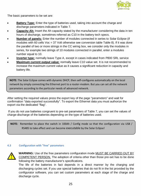
The basic parameters to be set are:
• Battery Type: Enter the type of batteries used, taking into account the charge and
discharge parameters indicated in Table 7.
• Capacity Ah: Insert the Ah capacity stated by the manufacturer considering the data in ten
hours of discharge, sometimes referred as C10 in the battery tech specs.
• Number of panels: Enter the number of modules connected in series to Solar Eclipse (if
modules with 60 cells Voc = 37 Volt otherwise see conversion table Table 8). If it was done
the parallel of two or more strings in the CC wiring box, we consider only the modules in
series, for example two strings of 10 modules connected in parallel, enter a modules
number equal to 10.
• Inverter type: normally leave Type A, except in cases indicated from P800 SRL service
• Maximum current output value: normally leave C10 value set. It is not recommended to
increase the maximum current value as it causes a significant reduction in capacity and
battery life.
After setting the required values press the export key of the page "parameters" and wait for confirmation "data exported successfully". To export the Ethernet data you must authorize the export via the dedicated "flag". If you do not use batteries congruent to pre-set parameters of Table 7, you can set the values of charge-discharge of the batteries depending on the type of batteries used.
4.3 Configuration with "free" parameters
WARNING: Use of the free parameters configuration mode MUST BE CARRIED OUT BY
COMPETENT PERSON. The adoption of criteria other than those pre-set has to be done
following the battery manufacturer's specifications.
The life of the batteries in fact depends in a direct manner by the charging and
discharging cycles set. If you use special batteries that do not fit in the list provided by the
configurator software, you can set custom parameters at each stage of the charge and
discharge cycle.
NOTE: Remember to place the switch in 100Ah / Config mode so that the configuration via USB /
RS485 to take effect and can become executable by the Solar Eclipse!
NOTE: The Solar Eclipse comes with dynamic DHCP, then self-configures automatically on the local
network by simply connecting the Ethernet port to a router-modem. But you can set all the network
parameters according to the particular needs of advanced network.
26
Please ALWAYS follow the battery manufacturer's recommendations to make sure that the
batteries are not damaged or may have a very short life.
In the "parameters" drop-down menu set "free parameters." It will appear on the right a series of
values to be set. After you type the correct values for the battery pack used, press the Export
button and start Solar Eclipse.
4.4 Solar Eclipse reboot procedure
Restarting the Solar Eclipse do not reset the parameters set via PC, however, it interrupt the
complete charging procedure and the charge status of the batteries is recalculated.
To restart the following steps:
• Lock Solar Eclipse holding down the button (2) to the left of the LEDs for more than 5
seconds (see Fig 1), or with the button in the Software Configurator
• Verify that the first LED on the left starts flashing
• Open the battery pack switch, disconnecting power from the Solar Eclipse
• Ensure that all the LEDs turn off
• Wait 3 minutes for the electrostatic charges are exhausted
• Close the batteries DC switch and repower the Solar Eclipse
• Unlock Solar Eclipse holding down the button (2) to the left of the LEDs for more than 5
seconds (see Fig 1), or with the button in the Software Configurator
• Verify that the first LED on the left emits steady light
4.5 Solar Eclipse reset procedure
WARNING: Resetting the Solar Eclipse will lose all configuration parameters. Do not do
this if you do not have all the data to make a new device programming.
The Reset procedure is only required in case of severe internal errors if the machine remains
locked without any alarm present (see troubleshooting paragraph 5.11).
To complete the Total Reset, press the hidden reset button located to the right of the Led (see
Figure 15) for more than 5 seconds and wait until all the red LEDs flash at the same time. Wait a
few moments, then restart (see 4.4).
27
4.6 Notes on the battery pack sizing
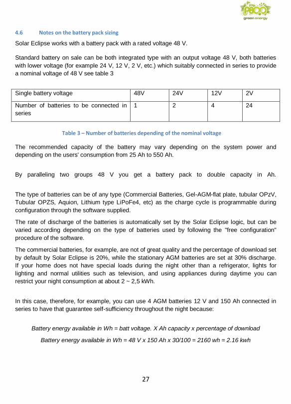
Solar Eclipse works with a battery pack with a rated voltage 48 V.
Standard battery on sale can be both integrated type with an output voltage 48 V, both batteries
with lower voltage (for example 24 V, 12 V, 2 V, etc.) which suitably connected in series to provide
a nominal voltage of 48 V see table 3
Single battery voltage 48V 24V 12V 2V
Number of batteries to be connected in
series
1 2 4 24
Table 3 – Number of batteries depending of the nominal voltage
The recommended capacity of the battery may vary depending on the system power and
depending on the users' consumption from 25 Ah to 550 Ah.
By paralleling two groups 48 V you get a battery pack to double capacity in Ah.
The type of batteries can be of any type (Commercial Batteries, Gel-AGM-flat plate, tubular OPzV,
Tubular OPZS, Aquion, Lithium type LiPoFe4, etc) as the charge cycle is programmable during
configuration through the software supplied.
The rate of discharge of the batteries is automatically set by the Solar Eclipse logic, but can be
varied according depending on the type of batteries used by following the "free configuration"
procedure of the software.
The commercial batteries, for example, are not of great quality and the percentage of download set
by default by Solar Eclipse is 20%, while the stationary AGM batteries are set at 30% discharge.
If your home does not have special loads during the night other than a refrigerator, lights for
lighting and normal utilities such as television, and using appliances during daytime you can
restrict your night consumption at about 2 ~ 2,5 kWh.
In this case, therefore, for example, you can use 4 AGM batteries 12 V and 150 Ah connected in
series to have that guarantee self-sufficiency throughout the night because:
Battery energy available in Wh = batt voltage. X Ah capacity x percentage of download
Battery energy available in Wh = 48 V x 150 Ah x 30/100 = 2160 wh = 2.16 kwh
28
If your home or your user has constant night time loads like a computer always on or electric
pumps for the pool operation or other, or even a freezer or other, your consumption may be around
4 ~ 5 kWh.
In this case, for example, you can connect 4 x 12 V and 200 Ah to the type OPzV gel that will grant
you self-sufficiency throughout the night because:
Battery energy available in Wh = batt voltage. X Ah capacity x percentage of download
Battery energy available in Wh = 48 V x 200 Ah x 50/100 = 4800 wh = 4,8 kwh
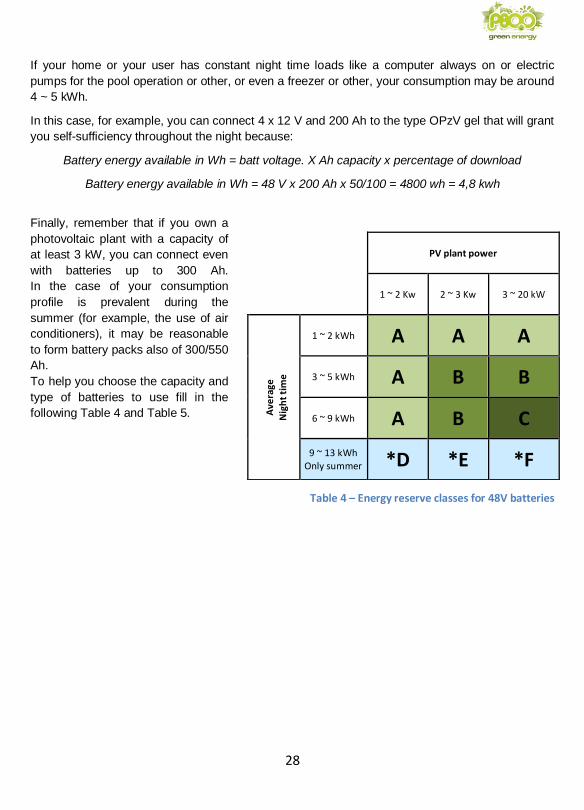
Finally, remember that if you own a
photovoltaic plant with a capacity of
at least 3 kW, you can connect even
with batteries up to 300 Ah.
In the case of your consumption
profile is prevalent during the
summer (for example, the use of air
conditioners), it may be reasonable
to form battery packs also of 300/550
Ah.
To help you choose the capacity and
type of batteries to use fill in the
following Table 4 and Table 5.
Table 4 – Energy reserve classes for 48V batteries
PV plant power
1 ~ 2 Kw 2 ~ 3 Kw 3 ~ 20 kW
Ave
rage
N
igh
t ti
me
1 ~ 2 kWh A A A
3 ~ 5 kWh A B B
6 ~ 9 kWh A B C
9 ~ 13 kWh Only summer *D *E *F
29
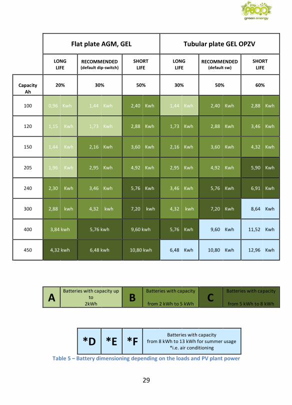
Table 5 – Battery dimensioning depending on the loads and PV plant power
Flat plate AGM, GEL Tubular plate GEL OPZV
LONG LIFE
RECOMMENDED (default dip-switch)
SHORT LIFE
LONG LIFE
RECOMMENDED (default sw)
SHORT LIFE
Capacity Ah
20% 30% 50% 30% 50% 60%
100 0,96 Kwh 1,44 Kwh 2,40 Kwh 1,44 Kwh 2,40 Kwh 2,88 Kwh
120 1,15 Kwh 1,73 Kwh 2,88 Kwh 1,73 Kwh 2,88 Kwh 3,46 Kwh
150 1,44 Kwh 2,16 Kwh 3,60 Kwh 2,16 Kwh 3,60 Kwh 4,32 Kwh
205 1,96 Kwh 2,95 Kwh 4,92 Kwh 2,95 Kwh 4,92 Kwh 5,90 Kwh
240 2,30 Kwh 3,46 Kwh 5,76 Kwh 3,46 Kwh 5,76 Kwh 6,91 Kwh
300 2,88 kwh 4,32 kwh 7,20 kwh 4,32 kwh 7,20 Kwh 8,64 Kwh
400 3,84 kwh 5,76 kwh 9,60 kwh 5,76 Kwh 9,60 Kwh 11,52 Kwh
450 4,32 kwh 6,48 kwh 10,80 kwh 6,48 Kwh 10,80 Kwh 12,96 Kwh
A Batteries with capacity up
to 2kWh
B Batteries with capacity
from 2 kWh to 5 kWh
C Batteries with capacity
from 5 kWh to 8 kWh
*D *E *F Batteries with capacity
from 8 kWh to 13 kWh for summer usage *i.e. air conditioning
30
4.7 Warnings and tips for the formation of the battery pack 48 V
The setup of the battery pack 48 V must be made in accordance with current standards by
qualified personnel. Below some important precautions and warnings to be followed to avoid
serious damage to property and people.a formazione del pacco batterie 48 V
CAUTION: The Solar Eclipse do not have the ISOLATION TRANSFORMER (transformer-less). This type involves the use of inverters with isolation transformer, or in case of inverter also without isolation transformer is necessary to maintain the battery pack floating with respect to earth: no pole must be connected to earth, also TERMINALS OF BATTERIES HAS TO BE PROTECTED WITH A DOUBLE INSULATION as they are located at the same potential of the network DANGEROUS FOR THE HUMAN BODY !!!
WARNING !!!: If the battery pack used is liquid electrolyte type, it must be installed in a
very well ventilated place and not in the same place as were the Solar Eclipse or inverter
are installed. battery pack locally widely ventilated and other than where there are
electrical devices such as inverters, panels and Solar Eclipse !!!
The use of liquid electrolyte batteries can cause highly explosive vapors !!!
WARNING: set the values of the charge cycle as recommended by the battery manufacturer.
WARNING: a non-conforming use of the charge cycle can cause damage and / or battery
explosion
To form a battery pack is advisable to follow the following minimum rules:
• Place a fuse 20 A more 'closely as possible to the same battery terminals
• Use a double insulated cable
• Insulate the battery terminals through appropriate cover terminals and shrink tubing
• Isolate the battery pack in a closed cabinet in fiberglass but provided with the ventilation
air vents, or in a metal cabinet ventilated and earthed
4.8 Warnings and parameters to be set on the grid inverter
WARNING: Do not use Solar Eclipse with inverters which have an MPPT operating voltage lower of 150 V. The operation of the inverter to tension lower than 150V may damage Solar Eclipse.
Some network inverters are not compatible with Solar Eclipse due to particular operating parameters. To check compatibility, see Appendix B at the bottom of this manual.
For all the inverters that have the ability to set the "Vstart" voltage start MPPT operation, set "Vstart" greater than 200 V if compatible with the string of photovoltaic modules.
31
MPPT anti-shadowing functions interrupt battery charge and may cause malfunctions of the "Solar
Eclipse-Inverter grid" storage system, and then turn off these features if possible through the
inverter configuration panel.
4.9 Inverter Power One / ABB
Enter the inverter settings menu by typing the default password **** (if not changed). From the
menu, select V start, and enter a value of at least 200 V. If the module string is very short, you can
drop off exceptionally at V start = 180 V.
Also from the settings menu, select > MPPT Scan (if available on the Power One / ABB model)
and set to Disable
4.10 Inverter SMA
Most SMA inverters come with a Sunny Explorer configuration program that interfaces with the
inverter via Bluetooth connection. Once the connection is stable, locate the section dedicated to
the CC settings and set V start = 250 V (minimum compatible with string length), V stop = 200 V
minimum, OptiTrac Global Peak = "OFF".
4.11 Inverter FRONIUS
To correctly set the new Fronius PRIMO models, you must enter the BASIC MENU by typing the
default password 22742 (if not edited), and set operating mode > MPPT > FIX = "Vmppt" by
entering the "Vmppt" value of the module string connected to Solar Eclipse. For example, if there
are 10 modules with Vmppt 31.5 V each, set MPPT > FIX = 315 V.
NOTE: Some SMA models have experienced malfunctions, to check the compatibility of your SMA
inverter model, check Appendix B at the bottom of the manual.
32
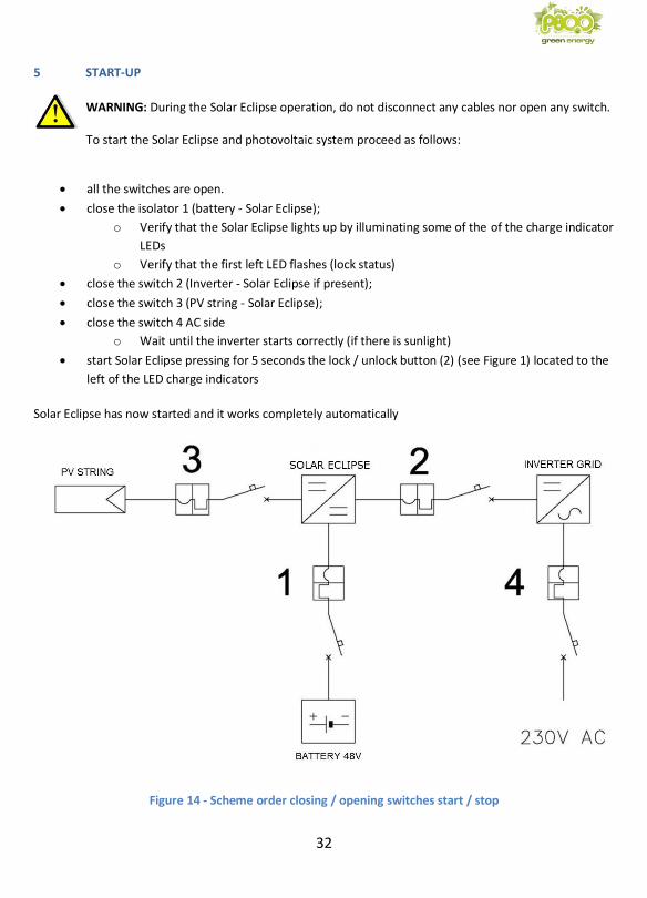
5 START-UP
WARNING: During the Solar Eclipse operation, do not disconnect any cables nor open any switch. To start the Solar Eclipse and photovoltaic system proceed as follows:
• all the switches are open.
• close the isolator 1 (battery - Solar Eclipse);
o Verify that the Solar Eclipse lights up by illuminating some of the of the charge indicator
LEDs
o Verify that the first left LED flashes (lock status)
• close the switch 2 (Inverter - Solar Eclipse if present);
• close the switch 3 (PV string - Solar Eclipse);
• close the switch 4 AC side
o Wait until the inverter starts correctly (if there is sunlight)
• start Solar Eclipse pressing for 5 seconds the lock / unlock button (2) (see Figure 1) located to the
left of the LED charge indicators
Solar Eclipse has now started and it works completely automatically
Figure 14 - Scheme order closing / opening switches start / stop
33
5.1 Stopping the Solar Eclipse
To stop the Solar Eclipse and photovoltaic system proceed as follows:
• Lock Solar Eclipse pressing the lock button /unlock (2) (see Figure 1) located to the left of
the LED charge indicators
• open the disconnecting switch 4 AC side
• open the switch 3 (PV string - Solar Eclipse)
• open the disconnecting switch 2 (Inverter - Solar Eclipse if present);
• open the isolator 1 (battery - Solar Eclipse)
5.2 Operation Modes
Solar Eclipse feeds itself from the battery pack, which in turn are loaded exclusively by
photovoltaic modules. Solar Eclipse works without the need for any external command with no
exchange of information with the drive and /or utilities.
The only external parameter Solar Eclipse use to determine its operation (in addition to the PV
modules) is that of the network power meter.
The goal of Solar Eclipse in fact is to keep close to zero as possible the value of the power
exchanged with the network: if we are taking energy from network, Solar Eclipse feeds the grid
inverter to increase the power produced from it. If we are emitting energy in the network, Solar
Eclipse draws power from the modules and stores it in the batteries.
5.3 Battery Charger Mode
If the power of the photovoltaic modules is higher than that required by the users the battery
charger mode activates automatically, drawing energy from the modules, and then decreases the
output power of the inverter grid.
NOTE: If with good solar irradiation the power of the inverter seems not to be adequate to the
photovoltaic field, this may mean that the Solar Eclipse is charging and therefore there is NO
ANOMALY OF OPERATION!
34
5.4 Night Mode delivery
During the hours without irradiation, Solar Eclipse powers the grid inverter with DC current and a power equal to that absorbed by the users.
If the batteries are depleted, the power needed by the users is taken from the network without having to do any operation.
5.5 Power mode
Solar Eclipse not only provides energy to the inverter at night, but also in all the moments in which the loads require a power that exceeds that provided by the photovoltaic modules.
In these cases, Solar Eclipse switches to "power supply" mode by increasing the apparent power of the photovoltaic field
Solar Eclipse does not go into “power supply” mode if the batteries are exhausted or if it is running a “full charge” cycle of the battery pack, see section 5.7 (cyclically).
5.6 Battery charger maintenance Mode
When the charging cycle is over and the power of the photovoltaic modules is still higher than the
consumption of the utilities, Solar Eclipse does not stop working but continues to power the battery
pack with a "maintenance" voltage as recommended by the manufacturers of batteries.
NOTE: If the battery power is not enough (for example in the case of batteries at the end of the
life cycle), the Solar Eclipse limits the power delivery to protect the battery pack from deep
discharges.
NOTE: The grid inverter output power can be greater than the power output of the PV modules
under the same irradiation conditions; this means that Solar Eclipse is helping to fuel the
photovoltaic field with energy from the battery pack!
35
5.7 Battery pack “full charge” mode
After a certain number of charge and discharge cycles, variable depending on the type and
capacity of the batteries, the weather conditions and the users' consumption, the Solar Eclipse
enters full charge mode.
In this phase the Solar Eclipse charge the batteries with the energy of the photovoltaic modules
completing a slow charge cycle.
The full charge cycle cannot be deleted because it is necessary to keep in good condition the
batteries and the proper functioning of Solar Eclipse system.
Solar Eclipse on these other situations may decide to automatically start a full charge:
• After a few hours of operation following the closure of the battery switch
• If the battery voltage drops below 44.0 V in the power supply mode
• If the battery voltage drops below 46.0 V during stand-by
5.8 Power-up and Power-off
The power up of Solar Eclipse takes place closing the battery if the voltage exceeds 40V. The power-off happens opening the battery switch.
5.9 Indicator lights
The Solar Eclipse operation is displayed in a simple and direct way via the LEDs located on the
front of the device.
When Solar Eclipse is powered by the battery pack 48 V always starts in "lock" mode, with the first
LED to the left flashing. In "Active mode" the first LED illuminates with a steady light.
The remaining LED indicated the available energy in the battery pack from which Solar Eclipse can
tap in case of energy needs from homes.
The LED number 9 (center) flashes when the output fuse is interrupted and simultaneously the
Solar Eclipse goes into a state of "LOCK", also the first LED on the left flashes.
When Solar Eclipse is in “full charge” mode, LEDs light up with a fixed light gradually from right to
left and then go off in reverse, up to a maximum of LEDs of the battery charge status.
Finally, if all LEDs are flashing, it has incurred a Reset or there is an ongoing failure alarm.
NOTE: During the full charge cycle Solar Eclipse never goes to the “power supply” mode either
during the day or during the night. In summer, the operation should be completed in one day
but in winter it is possible that it lasts for two or three days. Therefore, please do not be
alarmed if for a few days Solar Eclipse not operate even though the battery LEDs are all
switched on.
36
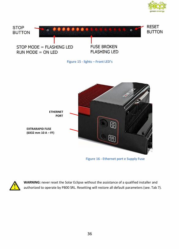
Figure 15 - lights – Front LED’s
ETHERNET
PORT
EXTRARAPID FUSE (6X32 mm 10 A – FF)
WARNING: never reset the Solar Eclipse without the assistance of a qualified installer and
authorized to operate by P800 SRL. Resetting will restore all default parameters (see. Tab 7).
Figure 16 - Ethernet port e Supply Fuse

37
5.10 Remote monitoring via Ethernet network jack
Solar Eclipse comes with a web-server ready to send all data to a cloud server at any moment,
allowing you to monitor the operation, status, alarms and saved parameters from any remote
location, as well as record production, consumption, and battery storage data.
If you have an optional "Monitoring Kit", then you can fully monitor the photovoltaic system using
the SolarApp application or installer portal.
To activate the plant monitoring kit, the installer must have registered the plant in advance at
http://www.solareclipse.it/en/tech-assistance-portal/
Upon registration, the installer must enter the activation codes on the kit. In this way, even the end
customer can monitor the system at any time and anywhere via Tablet or Smartphone.
Figure 17 – Installer monitoring portal
Solar Eclipse, is equipped with a RJ-45 port (see Figure 16) that allows connection to a local
network or directly to a computer.
The Solar Eclipse connection to a modem-router must be done with a normal LAN cable.
38
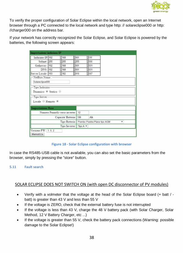
To verify the proper configuration of Solar Eclipse within the local network, open an Internet
browser through a PC connected to the local network and type http: // solareclipse000 or http:
//charger000 on the address bar.
If your network has correctly recognized the Solar Eclipse, and Solar Eclipse is powered by the
batteries, the following screen appears:
Figure 18 - Solar Eclipse configuration with browser
In case the RS485-USB cable is not available, you can also set the basic parameters from the
browser, simply by pressing the "store" button.
5.11 Fault search
SOLAR ECLIPSE DOES NOT SWITCH ON (with open DC disconnector of PV modules)
• Verify with a volmeter that the voltage at the head of the Solar Eclipse board (+ batt / -
batt) is greater than 43 V and less than 55 V
• If the voltage is ZERO, check that the external battery fuse is not interrupted
• If the voltage is less than 43 V, charge the 48 V battery pack (with Solar Charger, Solar
Method, 12 V Battery Charger, etc ...)
• If the voltage is greater than 55 V, check the battery pack connections (Warning: possible
damage to the Solar Eclipse!)
39
• If the voltage is correct (43 <V <55) disassemble the installer door, check the internal
battery fuses on the right side of the power board inside the Solar Eclipse
• If the fuses are interrupted check the polarity of the connections and replace the fuses (3
fuses 10 A 6x 32 AT type)
• If the fuses are not interrupted contact P800SRL Technical Support
SOLAR ECLIPSE DOES NOT START (first led to the left flashing)
• Verify that Solar Eclipse is on (LEDs on)
• Check with Software Configurator the presence of voltage from the grid (230 V)
• Check the correct installation and wiring of the Power Meter (make sure that the cable
does not get disturbed and use a "twisted" and shielded upper category cable)
• Check that the supply fuse is not interrupted (central LED must be fixed)
• Check with Software Configurator that the mains voltage is between 210 and 250 V and
the network frequency between 49 and 51 Hz
• Check that there is no alarm in the "trend" table (battery thermal alarm, supply or charger)
• Check in the "Advanced" tab that there is no internal alarm or "battery fault". If present,
click on "Reset Charge Fault"
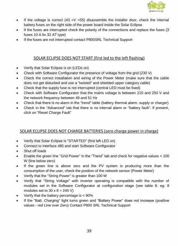
SOLAR ECLIPSE DOES NOT CHARGE BATTERIES (zero charge power in charge)
• Verify that Solar Eclipse is "STARTED" (first left LED on)
• Connect to interface 485 and start Software Configurator
• Shut off loads
• Enable the green line "Grid Power" in the “Trend” tab and check for negative values < 100
W (line below zero)
• If the green line is above zero and the PV system is producing more than the
consumption of the user, check the position of the network sensor (Power Meter)
• Verify that the "String Power" is greater than 100 W
• Verify that "String Voltage" with inverter operating is compatible with the number of
modules set in the Software Configurator at configuration stage (see table 8. eg: 8
modules set to 30 x 8 = 240 V)
• Verify that the battery percentage is < 90%
• If the "Batt. Charging" light turns green and “Battery Power” does not increase (positive
values - red Line over Zero) Contact P800 SRL Technical Support
40
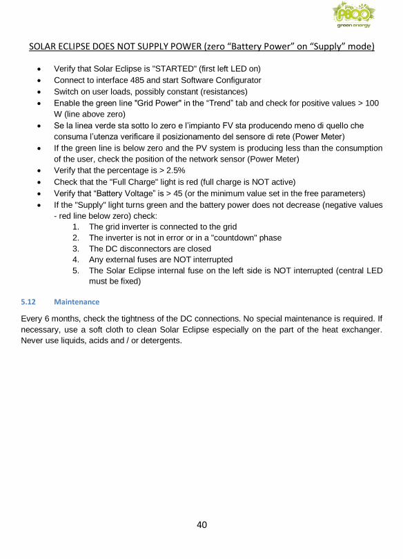
SOLAR ECLIPSE DOES NOT SUPPLY POWER (zero “Battery Power” on “Supply” mode)
• Verify that Solar Eclipse is "STARTED" (first left LED on)
• Connect to interface 485 and start Software Configurator
• Switch on user loads, possibly constant (resistances)
• Enable the green line "Grid Power" in the “Trend” tab and check for positive values > 100
W (line above zero)
• Se la linea verde sta sotto lo zero e l’impianto FV sta producendo meno di quello che
consuma l’utenza verificare il posizionamento del sensore di rete (Power Meter)
• If the green line is below zero and the PV system is producing less than the consumption
of the user, check the position of the network sensor (Power Meter)
• Verify that the percentage is > 2.5%
• Check that the "Full Charge" light is red (full charge is NOT active)
• Verify that “Battery Voltage” is > 45 (or the minimum value set in the free parameters)
• If the "Supply" light turns green and the battery power does not decrease (negative values
- red line below zero) check:
1. The grid inverter is connected to the grid
2. The inverter is not in error or in a "countdown" phase
3. The DC disconnectors are closed
4. Any external fuses are NOT interrupted
5. The Solar Eclipse internal fuse on the left side is NOT interrupted (central LED
must be fixed)
5.12 Maintenance
Every 6 months, check the tightness of the DC connections. No special maintenance is required. If
necessary, use a soft cloth to clean Solar Eclipse especially on the part of the heat exchanger.
Never use liquids, acids and / or detergents.
41
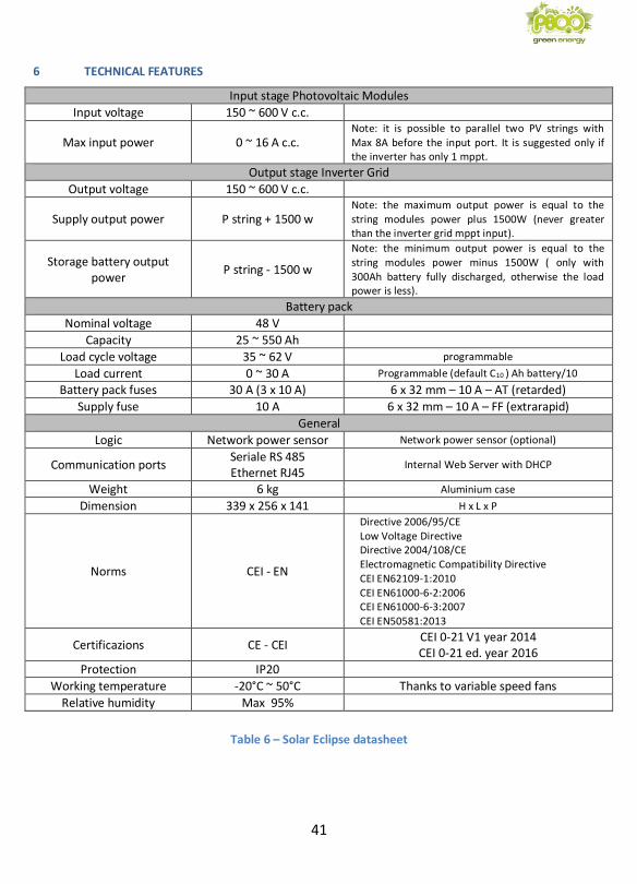
6 TECHNICAL FEATURES
Input stage Photovoltaic Modules
Input voltage 150 ~ 600 V c.c.
Max input power 0 ~ 16 A c.c. Note: it is possible to parallel two PV strings with Max 8A before the input port. It is suggested only if the inverter has only 1 mppt.
Output stage Inverter Grid
Output voltage 150 ~ 600 V c.c.
Supply output power P string + 1500 w Note: the maximum output power is equal to the string modules power plus 1500W (never greater than the inverter grid mppt input).
Storage battery output power
P string - 1500 w
Note: the minimum output power is equal to the string modules power minus 1500W ( only with 300Ah battery fully discharged, otherwise the load power is less).
Battery pack
Nominal voltage 48 V
Capacity 25 ~ 550 Ah
Load cycle voltage 35 ~ 62 V programmable
Load current 0 ~ 30 A Programmable (default C10 ) Ah battery/10
Battery pack fuses 30 A (3 x 10 A) 6 x 32 mm – 10 A – AT (retarded)
Supply fuse 10 A 6 x 32 mm – 10 A – FF (extrarapid)
General
Logic Network power sensor Network power sensor (optional)
Communication ports Seriale RS 485 Ethernet RJ45
Internal Web Server with DHCP
Weight 6 kg Aluminium case
Dimension 339 x 256 x 141 H x L x P
Norms CEI - EN
Directive 2006/95/CE Low Voltage Directive Directive 2004/108/CE Electromagnetic Compatibility Directive CEI EN62109-1:2010 CEI EN61000-6-2:2006 CEI EN61000-6-3:2007 CEI EN50581:2013
Certificazions CE - CEI CEI 0-21 V1 year 2014 CEI 0-21 ed. year 2016
Protection IP20
Working temperature -20°C ~ 50°C Thanks to variable speed fans
Relative humidity Max 95%
Table 6 – Solar Eclipse datasheet
42
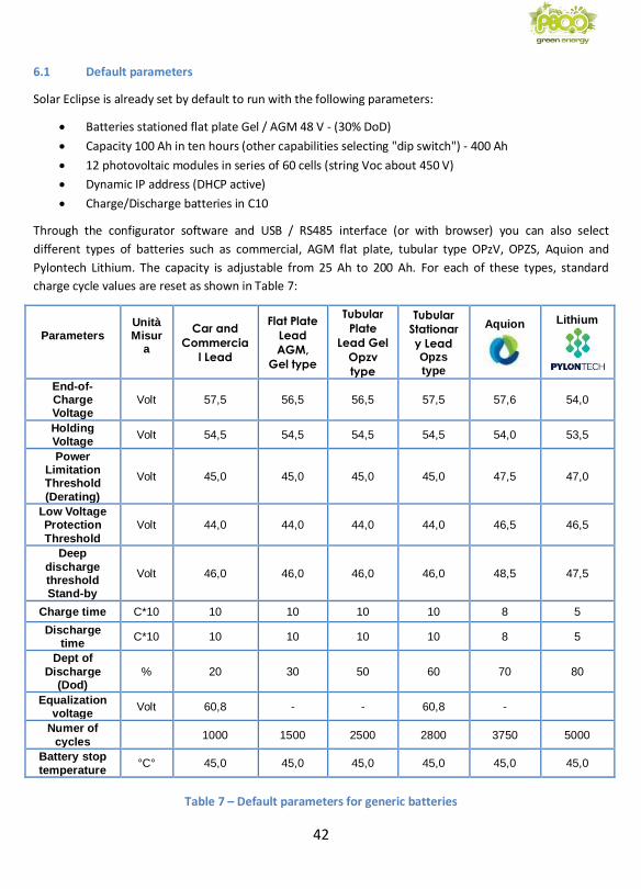
6.1 Default parameters
Solar Eclipse is already set by default to run with the following parameters:
• Batteries stationed flat plate Gel / AGM 48 V - (30% DoD)
• Capacity 100 Ah in ten hours (other capabilities selecting "dip switch") - 400 Ah
• 12 photovoltaic modules in series of 60 cells (string Voc about 450 V)
• Dynamic IP address (DHCP active)
• Charge/Discharge batteries in C10
Through the configurator software and USB / RS485 interface (or with browser) you can also select
different types of batteries such as commercial, AGM flat plate, tubular type OPzV, OPZS, Aquion and
Pylontech Lithium. The capacity is adjustable from 25 Ah to 200 Ah. For each of these types, standard
charge cycle values are reset as shown in Table 7:
Parameters
Unità Misur
a
Car and
Commercia
l Lead
Flat Plate
Lead
AGM,
Gel type
Tubular
Plate
Lead Gel
Opzv
type
Tubular
Stationar
y Lead Opzs
type
Aquion
Lithium
End-of-Charge Voltage
Volt 57,5 56,5 56,5 57,5 57,6 54,0
Holding Voltage
Volt 54,5 54,5 54,5 54,5 54,0 53,5
Power Limitation Threshold
(Derating)
Volt 45,0 45,0 45,0 45,0 47,5 47,0
Low Voltage Protection
Threshold
Volt 44,0 44,0 44,0 44,0 46,5 46,5
Deep
discharge threshold Stand-by
Volt 46,0 46,0 46,0 46,0 48,5 47,5
Charge time C*10 10 10 10 10 8 5
Discharge time
C*10 10 10 10 10 8 5
Dept of
Discharge (Dod)
% 20 30 50 60 70 80
Equalization voltage
Volt 60,8 - - 60,8 -
Numer of
cycles 1000 1500 2500 2800 3750 5000
Battery stop
temperature °C° 45,0 45,0 45,0 45,0 45,0 45,0
Table 7 – Default parameters for generic batteries
43
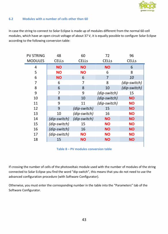
6.2 Modules with a number of cells other than 60
In case the string to connect to Solar Eclipse is made up of modules different from the normal 60-cell
modules, which have an open circuit voltage of about 37 V, it is equally possible to configure Solar Eclipse
according to the following conversion table:
PV STRING MODULES
48 CELLs
60 CELLs
72 CELLs
96 CELLs
4 NO NO NO 6 5 NO NO 6 8 6 NO 6 7 10 7 6 7 8 (dip-switch) 8 6 8 10 (dip-switch) 9 7 9 (dip-switch) 15
10 8 10 (dip-switch) NO 11 9 11 (dip-switch) NO 12 9 (dip-switch) 15 NO 13 10 (dip-switch) 16 NO 14 (dip-switch) (dip-switch) NO NO 15 (dip-switch) 15 NO NO 16 (dip-switch) 16 NO NO 17 (dip-switch) NO NO NO 18 15 NO NO NO
Table 8 – PV modules conversion table
If crossing the number of cells of the photovoltaic module used with the number of modules of the string
connected to Solar Eclipse you find the word "dip-switch", this means that you do not need to use the
advanced configuration procedure (with Software Configurator).
Otherwise, you must enter the corresponding number in the table into the “Parameters” tab of the
Software Configurator.
44
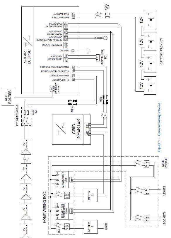
Figu
re 1
– G
ener
al w
irin
g sc
hem
e