solar guidelines and recognition program
TRANSCRIPT
SOLAR ENERGY SYSTEM DESIGN GUIDELINES & SOLAR RECOGNITION PROGRAM
December 2006, Prepared ByCOMMUNITY DEVELOPMENT DEPARTMENT
CITY OF SANTA BARBARA
How to Use These Guidelines
Are the guidelines mAndAtory or voluntAry?These guidelines are generally voluntary. They are not intended to prohibit, restrict or condition the use of any solar energy system for aesthetic reasons nor do they mandate solar energy use. The City encourages thoughtful consideration of these guidelines to achieve the goals listed above. Solar energy system designers or users who follow these guidelines can qualify for special recogni-tion from the City Council. (See page 5, for more information regarding the “Solar Design Recognition Program.”)
For projects that are required to receive Architectural Board of Review (ABR) or Historic Landmarks Commission (HLC) review, these guidelines will be used by the ABR and HLC to assist in determining the architectural appropriateness and neighborhood compatibility of the project.
Are the guidelines only for residentiAl buildings?The guidelines and the Solar Design Recognition Program are for all uses, including both residential and commercial.
Are the guidelines ApplicAble citywide?These guidelines and the Solar Design Recognition Program are applicable city-wide, in all zones, and in all neighborhoods.
do the guidelines focus only on photovoltAic systems?No, the guidelines address photovoltaic systems and solar thermal systems (e.g., solar hot water systems).
Purpose of These Guidelines
These guidelines provide guidance to property owners, architects, contractors and others who may be interested in using solar en-ergy in their buildings. The guidelines include general principles as well as specific techniques for designing solar energy systems that can take advantage of solar energy. The purpose of these guidelines is to achieve the following goals:
• Encourage solar energy system installation designs which are compatible with their neighborhood and which preserve the City’s historic and visual resources.
• Implement the Solar Recognition Program to publicly recognize high-performance, aesthetically designed solar installations which voluntarily comply with these guidelines.
• Promote early design consideration for integration of solar energy systems into new structures, additions and reroof projects.

introduction ......................................................... 1
Million Solar Roofs Program ........................... 1
Solar Design Recognition Program ................... 2
Permits for Solar Energy Systems ..................... 3
Santa Barbara’s Solar Orientation ..................... 4
solAr energy system technologies ........................ 5
Photovoltaic Systems ..................................... 5
Building-Integrated Photovoltaics .................... 8
Solar Thermal ............................................... 11
new construction And reroofing .......................... 13
solAr energy system guidelines And solAr recognition
AwArds ................................................................ 15
not publicly visible solAr energy system projects: not publicly visible ................................................ 15
Ideal Sites for Solar Installations ...................... 16
Flat-Roof Panel Systems ................................. 16
design chAllenge solAr energy system projects: publicly visible ....................................................... 17
Building Integrated Technologies ..................... 20 Carefully Designed and Mounted Panel Systems 22
þ Appropriate Size ...................................... 22
þ Panel Arrangement and Design .................... 23
þ System Infrastructure Screening ................... 26
þ Frame Color ............................................. 27
þ Glare ...................................................... 27
þ Mounting ................................................. 27 þ Ground-Mounted Systems .......................... 29
speciAl chAllenge solAr energy system projects ... 31
“Mission-Style” Tile Roofs .............................. 31
Historic District and Structures ........................ 32
Commercial Systems ...................................... 33
solAr design recognition progrAm checklist ........ 35
definitions ........................................................... 39
Table of Contents

Other City of Santa Barbara Solar Energy HandoutsThe following additional solar energy documents are available at the City of Santa Barbara’s Planning and Zoning Counter at 630 Garden Street:
• Get Started With Solar!• Passive Solar Building Design Guidelines &
Award Program• Solar Energy System References and Resources• Which Solar System Projects Require Design Review?

Solar EnErgy SyStEm DESign guiDElinES & Solar rEcognition awarD Program 1
INTRODUCTIONThe City of Santa Barbara enjoys an average of 300 sunny days per year. This sunny weather makes Santa Barbara well-suited for environmentally friendly solar energy use. Energy conservation and solar energy use are integral to sustainable building. The City encourages aesthetically designed solar energy use to protect and enhance the natural environment. Solar energy benefits include natural environment preservation and energy independence and security. Government rebates and tax incentives increase solar energy system affordability. Both photovoltaic systems, which produce electricity, and solar thermal systems, which heat air or water, are discussed in these guidelines.
Million Solar Roofs
Million Solar Roofs is a federal initiative with a goal of solar en-ergy systems to be installed on one million roofs in the U.S. by the year 2010. The City of Santa Barbara participates in the Million Solar Roofs Partnership in Santa Barbara County. The Partner-ship brings together business, government, the energy industry, and community organizations to further solar initiatives.
One barrier to solar energy use identified by the Santa Barbara County Million Solar Roofs Partnership is that the panelized de-sign of solar electric systems is often not considered compatible with existing community aesthetic standards and architectural requirements. This document encourages solar energy systems by providing specific guidance on how to create solar energy systems
“One City goal is to achieve and maintain a healthful natural environment”
“In keeping with our community’s values and the need to reduce the burden that our daily activities have on the natural environment, the City must take a more proactive approach and work to develop a sus-tainable community.”
Sustainable community/city: A community or city that meets its present needs without sacrificing the ability of future generations to meet their own needs. More specifically, a sustainable community is one that improves and enhances its natural, social and eco-nomic resources in ways that allow current and future members of the community to lead healthy, productive and satisfying lives.
– The Conservation Element of the City’s General Plan.
– The City of Santa Barbara’s Sustainable City Program’s First Annual Report.
with positive aesthetic qualities. Also, the Solar Design Recognition Program within these guidelines provides a way to publicly recog-nize high-performing, aesthetically designed solar projects.

city of Santa BarBara 2
Solar Design Recognition Program
The City’s Solar Design Recognition Program publicly acknowl-edges projects that achieve high performing solar system designs compatible with neighborhoods by following these guidelines.
The City Council annually recognizes projects in two categories:
1) Solar Energy System Recognition Awards, for photo-voltaic or solar thermal systems that follow these guide-lines, and
2) Passive Solar Building Recognition Awards for projects that follow the City’s Passive Solar Building Design Guidelines, available as a separate handout.
See page 35 to determine whether a solar energy system project qualifies for the recognition program.
Award winners receive an appreciation certificate and a tradition-ally styled exterior wall plaque in the shape of a sun symbol similar to the image on the cover of this document. The certificate and plaque are presented to award winners publicly each June at a City Council hearing.
existing solAr Access legislAtion And regulAtions
stAte legislAtion
These guidelines are consistent with the State of Califor-nia’s policy to “promote and encourage the use of solar energy systems and to limit obstacles to their use” as stated in legislation enacted in 2004 (Government Code 65850.5). These guidelines are also consistent with the State’s Solar Rights Act (Civil Code Section 714), Solar Easement Law (Civil Code Section 801 & 801.5, and Revenue and Taxation Code Section 73.
The State’s Solar Shade Control Act limits the amount of shade that a tree or shrub can cast onto a neighbor’s solar energy system after that system is installed (Public Resources Code 25980-25986). For more information, see the City’s “Solar Energy System References and Resources” handout.
city solAr Access ordinAnce
The City’s Solar Access Ordinance regulates the height of new residential development on the north side of properties. The ordinance ensures adequate access to sunlight is available on the south side of properties so that passive solar heating opportunities are available and solar energy systems can be installed.
Solar EnErgy SyStEm DESign guiDElinES & Solar rEcognition awarD Program 3
Permits for Solar Energy Systems
permits And Zoning ApprovAl
Building permits are required for all solar energy system instal-lations. Many solar system projects can qualify for an “over the counter” permit, while some may require a limited in-house review. The “Photovoltaic System Submittal Procedures” handout, avail-able at the Planning and Building and Safety Counters, describes the necessary submittal materials and installation requirements for photovoltaic systems. Solar energy systems must also comply with all Zoning Ordinance requirements. An “over-the-counter” approval from Zoning is possible for projects that:
• Comply with all Zoning Ordinance requirements, and;• Are less than 1,000 square feet or 10 kW AC, and;• Are not located in a special Design District, Historic
District, or the Demolition Review Study Area and are not on a City Landmark or Structure of Merit.
Projects that do not comply with the above criteria may need to go through normal Zoning plan check routing.
Any Zoning Ordinance violations on the property must be abated prior to building permit issuance. The State’s solar rights laws do not exempt solar energy systems from the City’s Zoning Ordinance enforcement procedures.
Santa Barbara’s Solar Orientation
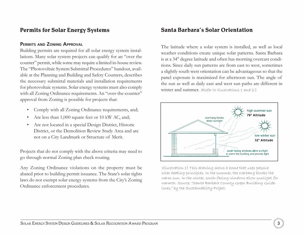
The latitude where a solar system is installed, as well as local weather conditions create unique solar patterns. Santa Barbara is at a 34° degree latitude and often has morning overcast condi-tions. Since daily sun patterns are from east to west, sometimes a slightly south west orientation can be advantageous so that the panel exposure is maximized for afternoon sun. The angle of the sun as well as daily east and west sun paths are different in winter and summer. (Refer to Illustrations 1 and 2.)
(Illustration 1) This drawing shows a home that uses passive solar heating principles. In the summer, the overhang blocks the warm sun. In the winter, south-facing windows allow sunlight for warmth. Source: “Santa Barbara County Green Building Guide-lines,” by the Sustainability Project.

city of Santa BarBara 4
(Illustration 2) This diagram shows the sun’s path from sunrise to sunset at summer and winter solstice from the perspective of the Santa Barbara County Courthouse.

Solar EnErgy SyStEm DESign guiDElinES & Solar rEcognition awarD Program 5
Solar Energy System Technologies
This section of the guidelines describes common solar energy technologies used to serve residential and commercial structure energy needs. Photovoltaic (electric) and solar thermal (water heating) technologies are briefly described. Solar technology which does not appear as a panel, or “building integrated” technologies are also introduced in this section. For more de-tailed information about solar technologies available, consult the separate “Solar Energy Systems Resources” handout at the Planning and Zoning Counter.
photovoltAic systemsPhotovoltaic systems convert the sun’s light into electrical energy. The energy is produced by photovoltaic (PV) cells, which are typically made of silicon. The electricity generated by a system travels through an inverter and then into a home or other building to provide for its energy needs. Some systems also have a battery to provide backup electricity. (Refer to Illustration 3.)
(Illustration 3) Source: “Building-Integrated Photovoltaic Designs for Commercial and Institutional Structures,” by Patrina Eiffert and Gregory J. Kiss

city of Santa BarBara 6
Most systems in Santa Barbara are grid-connected; they receive electricity from both the PV array and Southern California Edi-son’s electrical grid. When grid-connected systems generate more electricity than the building uses (such as on a sunny afternoon), the surplus electricity enters the grid. When the system produces less than the building uses (such as in the evening or when it is cloudy), SCE’s grid provides electricity to the building.
PV modules have no moving parts, typically require little main-tenance other than occasional rinsing and can last over 25 years. PV system costs depend on the system’s type and size. (Refer to
Illustrations 4 and 5.)
(Illustration 5) “Solar Energy Resource Guide, “ 6th Edition, by NorCal Solar.
(Illustration 4) This photovoltaic array produces electricity that is used to power a nearby home.
Solar EnErgy SyStEm tEchnologiES
Solar EnErgy SyStEm DESign guiDElinES & Solar rEcognition awarD Program 7
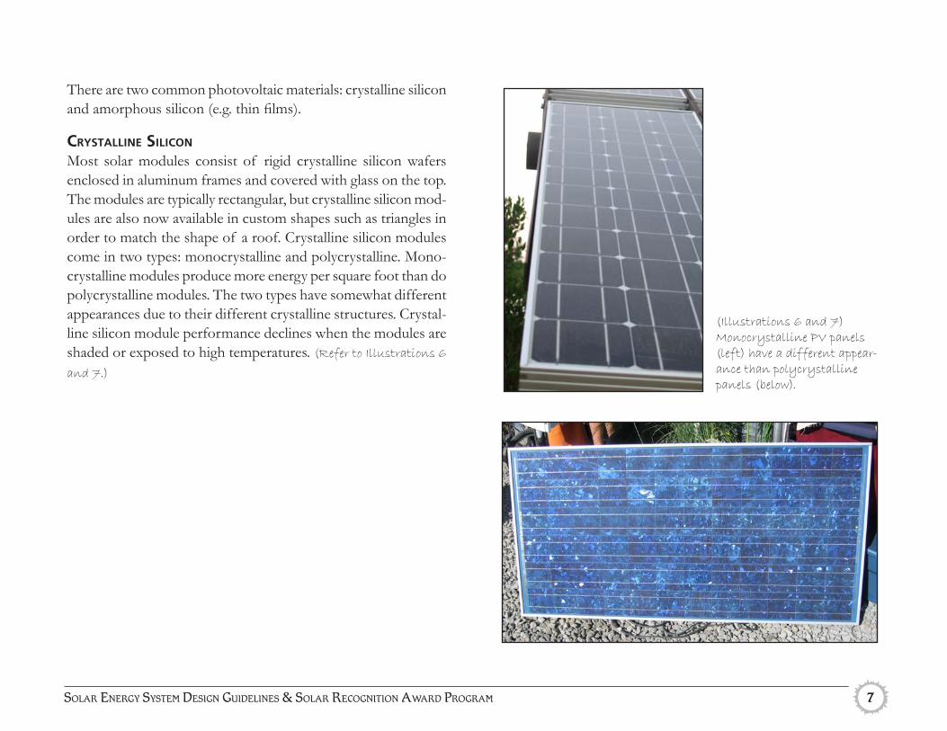
There are two common photovoltaic materials: crystalline silicon and amorphous silicon (e.g. thin films).
crystAlline silicon
Most solar modules consist of rigid crystalline silicon wafers enclosed in aluminum frames and covered with glass on the top. The modules are typically rectangular, but crystalline silicon mod-ules are also now available in custom shapes such as triangles in order to match the shape of a roof. Crystalline silicon modules come in two types: monocrystalline and polycrystalline. Mono-crystalline modules produce more energy per square foot than do polycrystalline modules. The two types have somewhat different appearances due to their different crystalline structures. Crystal-line silicon module performance declines when the modules are shaded or exposed to high temperatures. (Refer to Illustrations 6
and 7.)
(Illustrations 6 and 7) Monocrystalline PV panels (left) have a different appear-ance than polycrystalline panels (below).

city of Santa BarBara 8
Amorphous silicon (thin films)Amorphous silicon modules (e.g. thin films) are made by deposit-ing a very thin layer of PV silicon onto surfaces such as metal, glass or plastic. Thin films are amorphous (flexible) and do not need to be encased in frames or glass. They can be mounted discreetly on roof shingles or standing-seam metal roofs or in-corporated into windows. Thin films perform better in hot and shaded conditions than do crystalline silicon modules. However, compared to crystalline silicon modules, thin films are less avail-able commercially and require more surface area to produce the same amount of electricity. They may also not last as long as crystalline silicon modules. (Refer to Illustration 8.)
building-integrAted photovoltAics
Photovoltaic panels are most commonly mounted on top of roofs or on the ground. However, building-integrated photo-voltaic (BIPV) systems integrate PV material directly into the building’s materials such as the roof or glazing. BIPV systems can be particularly visually attractive because they are integrated with the building design. BIPV technologies include PV shingles or tiles, PV laminates, and PV glazing.
(Illustration 8) Thin-film photovoltaic materials are flexible and durable and can be applied to many different surfaces. Source: PowerFilm
Solar EnErgy SyStEm tEchnologiES

Solar EnErgy SyStEm DESign guiDElinES & Solar rEcognition awarD Program 9
photovoltAic shingles or tiles
BIPV roof shingles (aka “solar shingles” or “solar tiles”) function as regular shingles but have a PV material on the surface. Some manufacturers create shingles with a thin-film PV layer. Other manufacturers attach crystalline silicon PV cells to concrete tiles. Note that “tile” in this case does not refer to clay Mission-style tile or its look-a-likes.
Advantages of photovoltaic shingles include:
• No need for bulky panels and supports.• Function just as normal roofs do, with regular weather-
proofing and water-shedding abilities.• Look very similar to standard roofs. Solar shingles
can look somewhat blue or glossy relative to regular shingles when first installed, although they tend to look more normal within a few days as dust accumulates. Excessive dust should be cleaned off with water during the dry season in order to maintain performance. Right after rinsing, the original reflective appearance can re-turn for a few days.
• Can require less maintenance than traditional solar panels.
• Over time, the electricity generated by solar shingles can help offset the cost of a re-roof.
(Refer to Illustrations 9, 10 and 11.)
(Illustrations 9, 10 and 11) The solar shingles on the Arroyo Burro Watershed Resource Center function like a normal roof shingle. Photovaltaic cells are attached to the front exterior of the shingle.
16”
28”

city of Santa BarBara 10
(Illustration 13) Photovoltaic cells are embedded in the glass roof of this solarium. The roof lets in natural light while producing electricity. Source: Atlantis Energy Systems
photovoltAic lAminAtes
PV laminates are thin films laid in strips on sloped metal roofs. They cannot be installed on flat roofs; the angle must be at least 5°. Because the laminates can only be used on metal roofs, they tend to be most common on industrial and institutional buildings. (Refer to Illustration 12.)
photovoltAic glAZing
PV materials can also be integrated into glazing by, for example, sandwiching PV cells between two layers of glass. This permits light to enter the building, but the glass is not fully transparent. More transparent forms of PV glass are under development. PV glazing is typically used for glass facades on large commercial or industrial buildings. It can also be used for residential sunrooms but an overly large amount of glass may be needed to produce the same amount of electricity as other system types. (Refer to
Illustration 13.)
(Illustration 12) This elementary school’s standing seam roof is covered with solar laminates that produce electricity. Source: Akeena Solar.
Solar EnErgy SyStEm tEchnologiES
Solar EnErgy SyStEm DESign guiDElinES & Solar rEcognition awarD Program 11
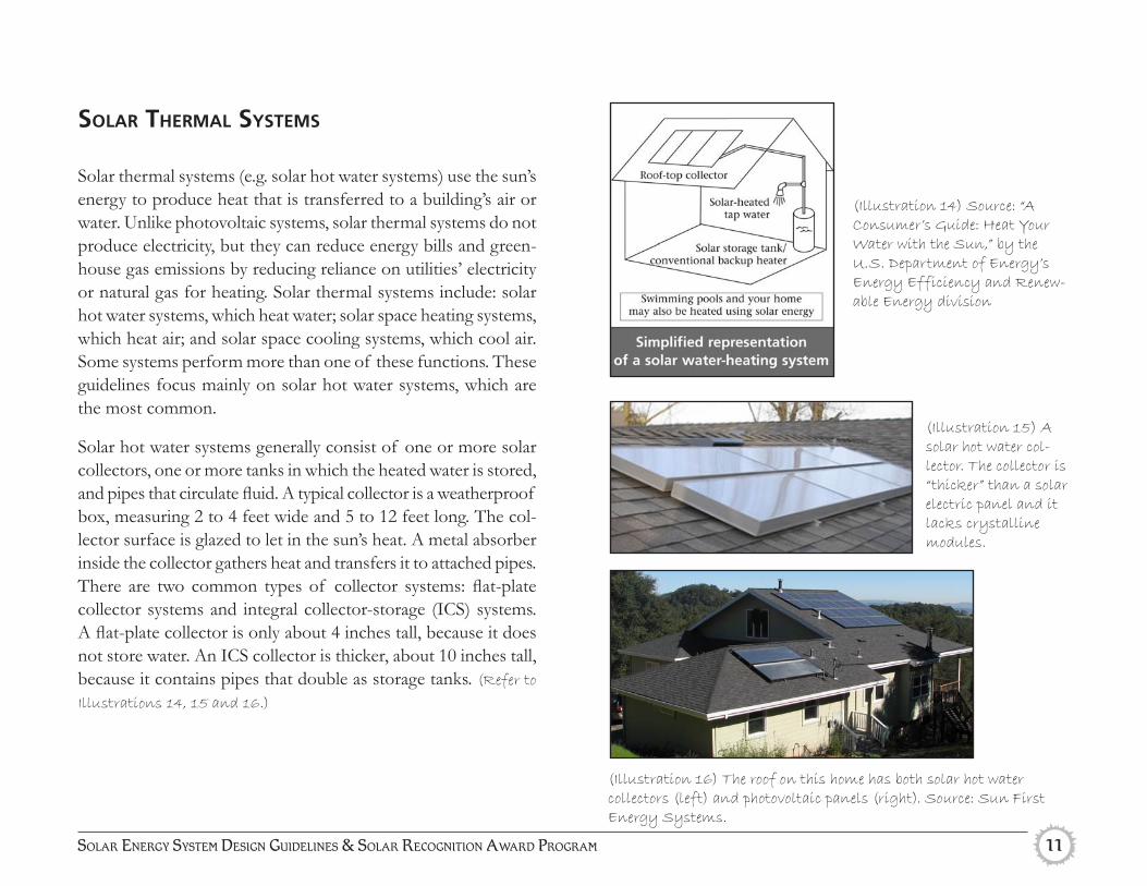
(Illustration 14) Source: “A Consumer’s Guide: Heat Your Water with the Sun,” by the U.S. Department of Energy’s Energy Efficiency and Renew-able Energy division
(Illustration 15) A solar hot water col-lector. The collector is “thicker” than a solar electric panel and it lacks crystalline modules.
(Illustration 16) The roof on this home has both solar hot water collectors (left) and photovoltaic panels (right). Source: Sun First Energy Systems.
solAr thermAl systems
Solar thermal systems (e.g. solar hot water systems) use the sun’s energy to produce heat that is transferred to a building’s air or water. Unlike photovoltaic systems, solar thermal systems do not produce electricity, but they can reduce energy bills and green-house gas emissions by reducing reliance on utilities’ electricity or natural gas for heating. Solar thermal systems include: solar hot water systems, which heat water; solar space heating systems, which heat air; and solar space cooling systems, which cool air. Some systems perform more than one of these functions. These guidelines focus mainly on solar hot water systems, which are the most common.
Solar hot water systems generally consist of one or more solar collectors, one or more tanks in which the heated water is stored, and pipes that circulate fluid. A typical collector is a weatherproof box, measuring 2 to 4 feet wide and 5 to 12 feet long. The col-lector surface is glazed to let in the sun’s heat. A metal absorber inside the collector gathers heat and transfers it to attached pipes. There are two common types of collector systems: flat-plate collector systems and integral collector-storage (ICS) systems. A flat-plate collector is only about 4 inches tall, because it does not store water. An ICS collector is thicker, about 10 inches tall, because it contains pipes that double as storage tanks. (Refer to
Illustrations 14, 15 and 16.)

city of Santa BarBara 12
building-integrated systems are not glazed. However, building-integrated systems are much larger, occupying entire roof planes, and thus produce the same total heat output and utility bill savings as collector boxes. Building-integrated solar thermal systems can be combined with photovoltaic shingles or other photovoltaic technologies. (Refer to Illustrations 17 and 18.)
building-integrAted solAr thermAl systems
In a typical building-integrated solar thermal system, the collec-tors form part of the roof. Instead of absorbing heat in a glazed collector box mounted on the roof surface, building-integrated systems absorb heat directly from the roof. This works because certain roof materials (such as metal and cement tiles) conduct heat relatively well. Building-integrated solar thermal systems are not appropriate for other roof materials because they do not transfer enough heat. Many building-integrated solar thermal sys-tems have no visual impact because they are located underneath the roof surface. Some of these systems contain a thin layer of heat-absorbing pipes underneath the roof surface. In other systems, a pocket of air underneath the roof surface is heated and then transferred through ducts to the building’s mechanical water heating or space heating equipment.
Building-integrated solar thermal systems can have higher upfront costs (roughly 10-20% more) than installing glazed flat-plate col-lectors if the costs of installing a new roof are included. Installing a new roof is the main expense in most building-integrated solar thermal systems, so incorporating a system into a desired or need-ed re-roof project can pose few additional costs. The systems also have longer life expectancies than traditional collector systems (up to 50 years as opposed to 15-20 years), allowing for greater long-term savings. Building-integrated systems produce less heat per square foot than do other solar thermal systems because the
(Illustrations 17 and 18) Building-integrated solar hot water sys-tems can be installed inside the roof (above), making them invisible when the roof is completed (below).
Solar EnErgy SyStEm tEchnologiES

Solar EnErgy SyStEm DESign guiDElinES & Solar rEcognition awarD Program 13
When a new home, addition or reroof is contemplated, it is a good time to think about how to accommodate solar energy sys-tems into the project. Consider installing a solar system as part of the project, as the cost of the solar system can be reduced by combining its installation with other work. Also, federal tax credits and state grants are highest in 2006 and the state rebate is scheduled to slightly decrease each year through 2017.
If budget constraints are great, at least design the project so that there is a high performance, attractive location for a solar energy system to be installed in the future. Coordinating the design of the system and the design of the building will help ensure that a high-performance, attractive system can be easily installed later. Planning ahead for a solar system location can also ensure a system can fit in well on a structure, rather than needing to be placed elsewhere on the site where ground permeability might be lost.
Review the City and Community Environmental Council’s “Get Started With Solar” Brochure, available as a separate handout. Consider where a system could be located, what size it would need to be and how it might be laid out. Following are some specific techniques for addressing solar energy systems when designing new construction.
New Construction and Reroofing
All buildings:
At A minimum:þ Design one section of roof with at least 300 square feet
of space for solar installations, where all mechanical equip-ment and skylights are absent, preferably south-facing at an angle close to 30°, not visible from public areas and free of shading. Many architectural styles accommodate a 30° roof slope, are appropriate to Santa Barbara and are compatible with photovoltaic panels and solar hot water systems.
þConsider an architectural style that includes a “flat” roof with a parapet architectural feature. Mission Revival, Italianate, and some neo-classical architectural styles commonly can include a parapet roof system. Parapet roof systems can very effectively and attractively screen solar energy systems, as illustrated on page 31.
þChoose plant and tree types and locations so that plants will not grow to shade areas on the property or on neighboring properties where solar energy systems are installed.
þDesign and locate structures so they will not shade areas on the property or on neighboring properties where solar energy systems are installed.
city of Santa BarBara 14
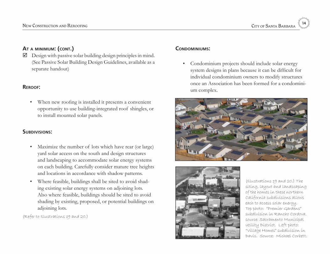
condominiums:
• Condominium projects should include solar energy system designs in plans because it can be difficult for individual condominium owners to modify structures once an Association has been formed for a condomini-um complex.
At A minimum: (cont.)þDesign with passive solar building design principles in mind.
(See Passive Solar Building Design Guidelines, available as a separate handout)
reroof:
• When new roofing is installed it presents a convenient opportunity to use building-integrated roof shingles, or to install mounted solar panels.
subdivisions:
• Maximize the number of lots which have rear (or large) yard solar access on the south and design structures and landscaping to accommodate solar energy systems on each building. Carefully consider mature tree heights and locations in accordance with shadow patterns.
• Where feasible, buildings shall be sited to avoid shad-ing existing solar energy systems on adjoining lots. Also where feasible, buildings should be sited to avoid shading by existing, proposed, or potential buildings on adjoining lots.
(Refer to Illustrations 19 and 20.)
nEw conStruction anD rEroofing
(Illustrations 19 and 20.) The siting, layout and landscaping of the homes in these northern California subdivisions allows each to access solar energy. Top photo: “Premier Gardens” subdivision in Rancho Cordova. source: Sacramento Municipal Utility District. Left photo: “Village Homes” subdivision in Davis. Source: Michael Corbett.

Solar EnErgy SyStEm DESign guiDElinES & Solar rEcognition awarD Program 15
Please note, Passive Solar Recognition Awards are also available, see the City’s Passive Solar Design Guidelines for more informa-tion on that program.
not publicly visible solAr energy system projects: “Not Publicly Visible” Solar projects have minimal design chal-lenges in comparison to other site locations and layouts. Not publicly visible Solar Recognition awards are given where high-performance solar panels are relatively easy to locate substantially outside of the public view. The award recognizes the installer for prudently taking advantage of site conditions amenable to solar. Other guidelines in the “Design Challenge” and “Special Chal-lenge” sections of this document do not necessarily need to be followed where solar panels are not visible from the street. Not Publicly Visible Solar Energy System Projects include:
not publicly visible cAtegory 1: Ideal Site Solar Installations
not publicly visible cAtegory 2:Flat-Roof-Mounted Solar Energy Systems
SOLAR ENERGY SYSTEM DESIGN GUIDELINES AND AWARDS
Following these guidelines can achieve a high performing solar installation design that preserves neighborhood and community character. These Guidelines also provide guidance for “challeng-ing” solar sites, where panels are visible to the public, so that the panels become a neighborhood enhancement through superior design techniques.
Projects that meet the Solar Design Recognition Program check-list items can qualify for a Solar Energy System Recognition Award. Three types of projects can be recognized with a Solar Energy System Recognition Award:
1) “Not Publicly Visible” Solar Recognition Projects, where site conditions allow for a high performing solar system to be located outside of the public view;
2) “Design Challenge” Recognition Projects, where site visibility conditions require careful design to achieve aesthetic goals; and
3) “Special Challenge” Recognition Projects, where “Mission-style” tile roofs, historic structures or com-mercial buildings create special design challenges.

city of Santa BarBara 16
not publicly visible project cAtegory 1: ideAl site solAr instAllAtions
The ideal location for a solar energy system in Santa Barbara is:
• On a flat lot in an Infill area (not in the Hillside Design District)
• Facing the south side of a lot, behind a main structure which shields the solar system from view from the street
• In a location where no vegetation or structures would cast shadows onto the system in a way that would de-crease system performance by more than 15%
• No public park, beach or trail with views of the site to the south of the lot
• Not in a historic district or on a historic structure
þThe solar system is proposed on an ideal high performance solar system site, out of the public view.
Where it is possible to install a solar panel in such an ideal lo-cation, any type of solar system design or mounting is accept-able and may achieve a Solar Recognition Award because the project is not publicly visible. The City encourages all property owners with ideal solar sites to consider installing high per-forming Solar Energy Systems shielded from public view. Of course, more visible locations are also appropriate for solar
energy systems, but more consideration of aesthetic concerns and system performance is recommended for non-ideal sites.
not publicly visible project cAtegory 2: flAt-roof pAnel systems
Systems mounted on flat roofs can usually easily be installed so they are not visible from public areas. South- and southwest-fac-ing systems aiming for optimal system performance would be angled well above the roof, making them visible from below if there is no screening parapet. Consider angling panels at a flatter angle if this will reduce their visibility. Panels mounted at a 5° angle versus an ideal 30° angle do not lose more than 15% of performance. Acceptable flat roof panel systems meet both of the following criteria.
þ The flat-roof panel system successfully uses one of the fol-lowing solutions:
• An architecturally compatible parapet hides the angled system from public view (Refer to Illustration 37), or
• The system is placed far enough toward the rear of large buildings so the system will not be visible from public areas, or
• If the system is visible, it is mounted at an angle of no more than 5° from the roof surface.
þ If the system will be visible from buildings above, the panels are organized into simple, rectangular groups.
not PuBlicly ViSiBlE ProjEctS

Solar EnErgy SyStEm DESign guiDElinES & Solar rEcognition awarD Program 17
design chAllenge solAr energy system projects: publicly visible
Design Challenge Solar Energy System Projects are projects where high-performance solar panels cannot be located sub-stantially outside of the public view. Special effort to carefully choose an appropriate solar technology type, aesthetically place and carefully mount the panel is required for an appropriate publicly visible solar panel installation. The Design Challenge Solar Energy System award recognizes the special effort which applicants for these Solar Energy Systems have made to create an aesthetically integrated solar system installation. The “easiest” solution, where the least amount of special design may be needed, in this category is to use “building-integrated” technologies. These technologies can easily blend in with buildings unless a building is historic or has a tile roof. Roof-mounted panel systems visible from the street must carefully follow the mounting and general visibility reduction and integration techniques in “Category 2” to be eligible for a Solar Recognition Award. Acceptable Design Challenge Solar projects are in the following categories:
design chAllenge cAtegory 1: Building-Integrated Technologies Solar Energy Systems(For more details see page 20.)
design chAllenge cAtegory 2: Carefully Designed and Mounted Panel Solar Energy Systems (For more details see page 22.)
Following are two summary tables that can assist with general solar energy system technology, location and design choices.
(Illustration 21.) Category 1: An example of building integrated solar energy system technology. Source: Atlantis Energy Systems.
Solar Shingles
(Illustration 22.) Category 2: An example of a “carefully designed and mounted panel solar energy system”. Source: R&M Technologies
city of Santa BarBara 18
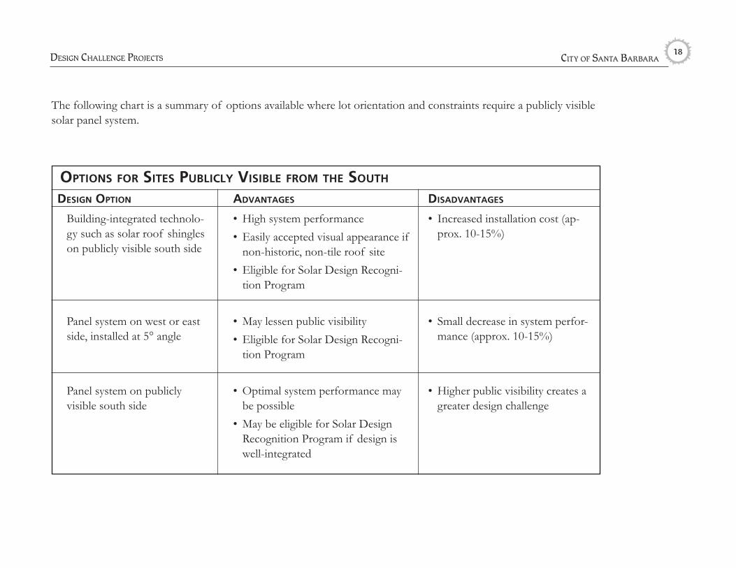
The following chart is a summary of options available where lot orientation and constraints require a publicly visible solar panel system.
design option
Building-integrated technolo-gy such as solar roof shingles on publicly visible south side
Panel system on west or east side, installed at 5° angle
Panel system on publicly visible south side
AdvAntAges
• High system performance• Easily accepted visual appearance if
non-historic, non-tile roof site• Eligible for Solar Design Recogni-
tion Program
• May lessen public visibility• Eligible for Solar Design Recogni-
tion Program
• Optimal system performance may be possible
• May be eligible for Solar Design Recognition Program if design is well-integrated
disAdvAntAges
• Increased installation cost (ap-prox. 10-15%)
• Small decrease in system perfor-mance (approx. 10-15%)
• Higher public visibility creates a greater design challenge
options for sites publicly visible from the south
DESign challEngE ProjEctS
Solar EnErgy SyStEm DESign guiDElinES & Solar rEcognition awarD Program 19
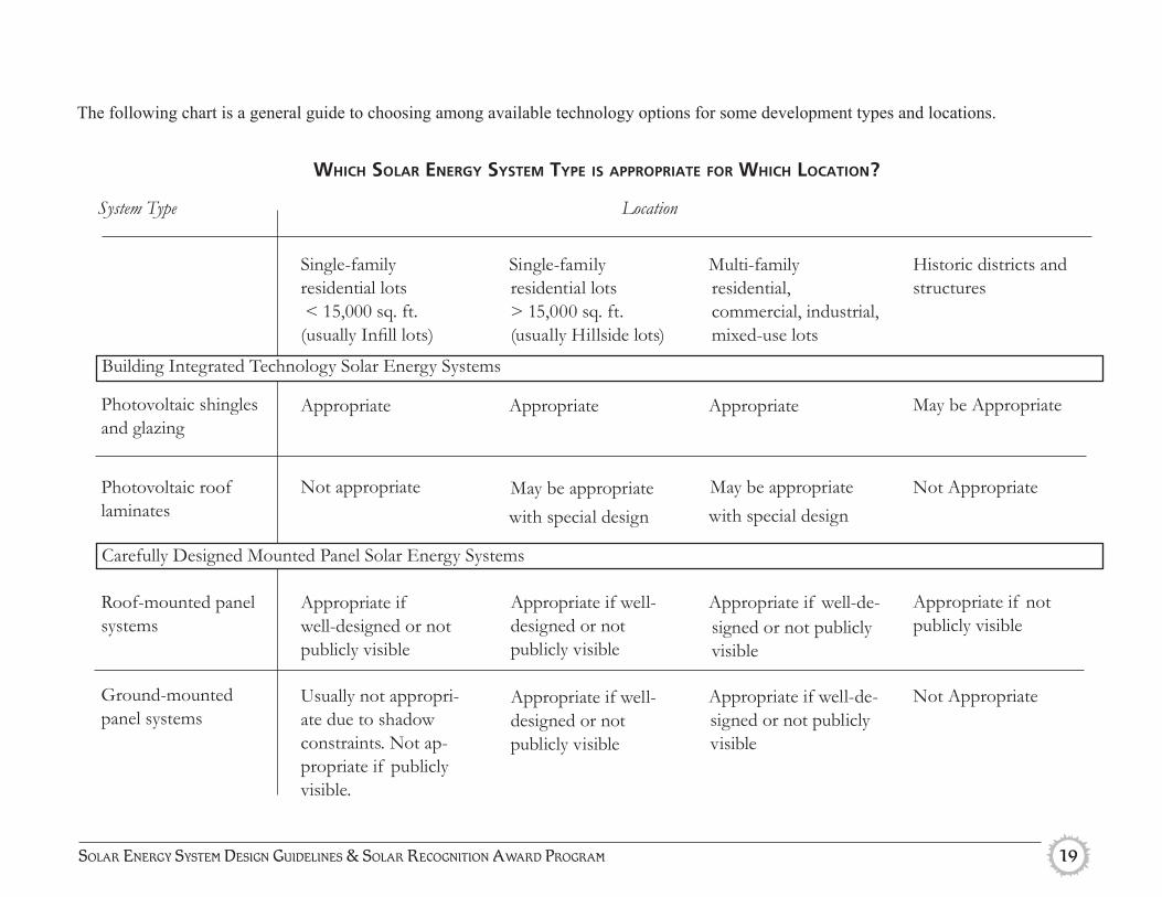
Thefollowingchartisageneralguidetochoosingamongavailabletechnologyoptionsforsomedevelopmenttypesandlocations.
Photovoltaic shingles and glazing
Photovoltaic roof laminates
Roof-mounted panel systems
Ground-mounted panel systems
Historic districts and structures
May be Appropriate
Not Appropriate
Appropriate if not publicly visible
Not Appropriate
Single-family residential lots < 15,000 sq. ft. (usually Infill lots)
Appropriate
Not appropriate
Appropriate if well-designed or not publicly visible Usually not appropri-ate due to shadow constraints. Not ap-propriate if publicly visible.
Single-family residential lots > 15,000 sq. ft. (usually Hillside lots)
Appropriate
May be appropriatewith special design
Appropriate if well-designed or not publicly visible Appropriate if well-designed or not publicly visible
Multi-family residential, commercial, industrial, mixed-use lots
Appropriate
May be appropriatewith special design
Appropriate if well-de-signed or not publicly visible
Appropriate if well-de-signed or not publicly visible
which solAr energy system type is AppropriAte for which locAtion?
System Type Location
Building Integrated Technology Solar Energy Systems
Carefully Designed Mounted Panel Solar Energy Systems
city of Santa BarBara 20
design chAllenge cAtegory 1: building-integrAted technologies
Building-integrated photovoltaic technologies (such as solar shingles, roof laminates and glazing) and building-integrated solar thermal technologies generally blend in extremely well with existing environments Technology in this area is rapidly evolv-ing. As new innovative technologies evolve, these guidelines may need to be updated and new technologies can be evaluated on a case by case basis.
Building integrated technologies may be appropriate on desig-nated historic resources and historic districts if installation of the system does not alter the character defining features of the building or pose a negative impact on its historic setting. It is always preferred that building integrated technologies be installed on portions of the building that are not visible from the public right-of-way. Proposed installation of building integrated tech-nologies on historic structures or within historic districts would be evaluated on a case by case basis.
These Solar Energy Systems are more expensive than regular so-lar panel systems and the City recognizes the special investments homeowners may make for these aesthetically beneficial systems as valuable to the community. Building-integrated technologies are acceptable, and eligible for a Solar Recognition Award, if the project is not on a historic resource site and the following crite-ria are met. See page 35 for a summary of Building Integrated Technology concepts.
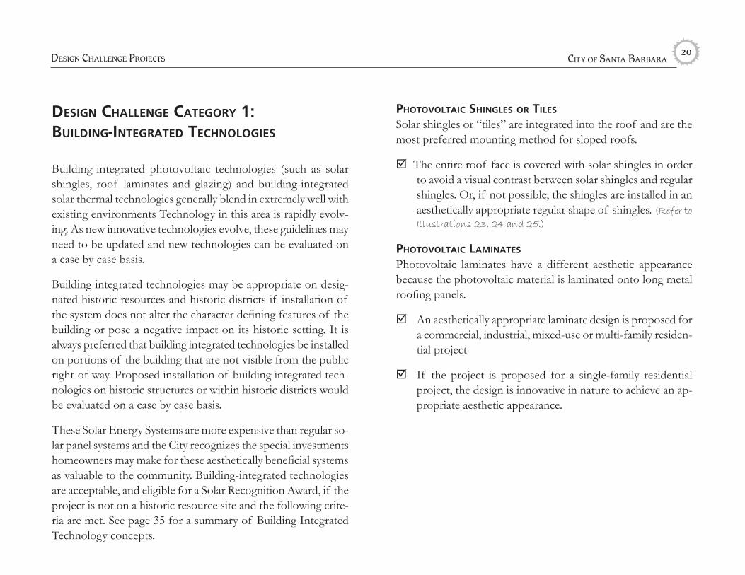
photovoltAic shingles or tiles
Solar shingles or “tiles” are integrated into the roof and are the most preferred mounting method for sloped roofs.
þ The entire roof face is covered with solar shingles in order to avoid a visual contrast between solar shingles and regular shingles. Or, if not possible, the shingles are installed in an aesthetically appropriate regular shape of shingles. (Refer to
Illustrations 23, 24 and 25.)
photovoltAic lAminAtes
Photovoltaic laminates have a different aesthetic appearance because the photovoltaic material is laminated onto long metal roofing panels.
þ An aesthetically appropriate laminate design is proposed for a commercial, industrial, mixed-use or multi-family residen-tial project
þIf the project is proposed for a single-family residential project, the design is innovative in nature to achieve an ap-propriate aesthetic appearance.
DESign challEngE ProjEctS

Solar EnErgy SyStEm DESign guiDElinES & Solar rEcognition awarD Program 21
photovoltAic glAZing
Photovoltaic glazing is rare for small-scale projects but may become more common eventually. Photovoltaic glazing may be useful wherever a large, semi-transparent or opaque glass surface is desired.
þ An aesthetically appropriate PV glazing design is proposed for a large commercial or industrial project’s atriums, awnings, walls or roofs.
þ If the PV glazing is proposed for a residential structure, the design is innovative in nature to achieve an appropriate aesthetic appearance.
building-integrAted solAr thermAl technologies
Consider using building-integrated solar thermal technologies so that solar thermal systems are not visible from public areas. Solar thermal building-integrated systems require a cement or metal roof.
þ A cement or metal roof is proposed on a commercial non-historic structure.
þ A cement-tile roof is proposed with the system on a single-family structure, where the cement-tile roof would be con-sidered compatible with the neighborhood.
þA cement-tile roof is proposed in a historic district or on a historic structure if a cement-tile roof is appropriate for the historic district or structure.
(Illustration 23) Photovoltaic shingles are best integrated when they cover the entire roof so as not to contrast with the other shingles. Source: Atlantis Energy Systems.
(Illustration 24) The shingles on the top section appear slightly different than the rest of the roof, but overall, integrate well. Source: Atlantis Energy Systems.
Solar Shingles
(Illustration 25) These solar roofing tiles have been applied in a way that creates irregular shapes on the roof and the tiles do not com-pletely cover the entire roof plane.
city of Santa BarBara 22
design chAllenge cAtegory 2: cArefully designed And mounted pAnel systems
Publicly visible solar energy systems which do not use building-integrated technologies require special attention to placement and design to ensure a pleasing appearance. For a mounted solar system design to be considered well integrated with a building, it should meet criteria in all of the following categories:
• Appropriate Size• Least Visible High-Performance Location• Panel Arrangement and Design• System Infrastructure Screening• Frame Color• Glare• Mounting
Ground mounted systems are also subject to additional criteria. Publicly visible panel systems that meet all of the criteria catego-ries are eligible for a design award as part of the Solar Design Recognition Program, whereas publicly visible systems that are not well-integrated are not eligible. See page 36 for a summary of carefully designed and mounted panel system concepts.
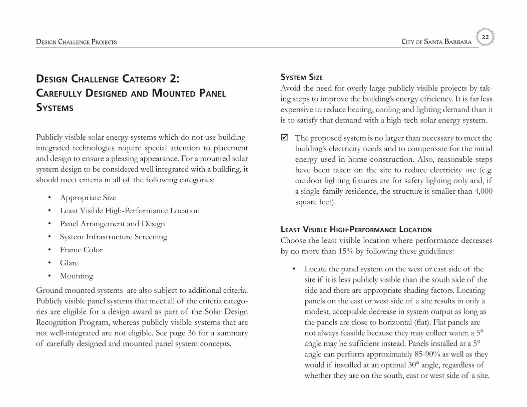
system siZe
Avoid the need for overly large publicly visible projects by tak-ing steps to improve the building’s energy efficiency. It is far less expensive to reduce heating, cooling and lighting demand than it is to satisfy that demand with a high-tech solar energy system.
þ The proposed system is no larger than necessary to meet the building’s electricity needs and to compensate for the initial energy used in home construction. Also, reasonable steps have been taken on the site to reduce electricity use (e.g. outdoor lighting fixtures are for safety lighting only and, if a single-family residence, the structure is smaller than 4,000 square feet).
leAst visible high-performAnce locAtion Choose the least visible location where performance decreases by no more than 15% by following these guidelines:
• Locate the panel system on the west or east side of the site if it is less publicly visible than the south side of the side and there are appropriate shading factors. Locating panels on the east or west side of a site results in only a modest, acceptable decrease in system output as long as the panels are close to horizontal (flat). Flat panels are not always feasible because they may collect water; a 5° angle may be sufficient instead. Panels installed at a 5° angle can perform approximately 85-90% as well as they would if installed at an optimal 30° angle, regardless of whether they are on the south, east or west side of a site.
DESign challEngE ProjEctS

Solar EnErgy SyStEm DESign guiDElinES & Solar rEcognition awarD Program 23
leAst visible high-performAnce locAtion (continued)• Locate systems on the rear façade of a building, on
accessory structures or in another less visible location if shade patterns would not significantly compromise system performance.
• Only mount panels on the roof. Do not consider pro-jecting panels from walls or other parts of structures, unless it is a commercial structure creating a well de-signed “awning” with the solar panels.
• Consider whether shadow-tolerant panels would make a less visible location feasible.
þ The system is located in the least visible location where at least 85% of optimal system performance can be achieved.
pAnel ArrAngement And design
Roof-mounted systems are very common in Santa Barbara and can be highly visible. Panel systems mounted on sloped roofs should be incorporated or integrated into the structure design. This topic is important. Seven concepts and illustrations of this topic follow on the next four pages.
1. Consider the panels as part of the overall design composi-tion. Match the shape and proportions of the array with the shape and proportions of the roof. (Refer to Illustrations 26
and 27.)
(Illustration 27) These panels are not well-proportioned to the roof. They visually overwhelm the structure. Source: “Design Guidelines for Historic Districts in the City of Pasadena, California”
(Illustration 26) This system matches the shape and proportions of the roof. Source: Sun First! Energy Systems

city of Santa BarBara 24
3. Consistently cover the entire roof face with the array if possible. If not possible, either:
a. aim for a regularly shaped rectangle of panels; or (Refer to Illustrations 31 and 32.)
b. use custom panel shapes to match the shape of the roof. Some manufacturers will create custom panel shapes such as triangles. (Refer to Illustrations 33 and
34.) If the roof is not entirely covered with panels, avoid leaving small or thin portions of the roof sur-rounding the array. Allow roof elements to remain which have enough size to appear intentional and hold their visual “weight” in the overall design composition.
pAnel ArrAngement And design (continued)
2. Installations on single-plane roofs are preferable because ar-rays can create a disjointed appearance on multi-plane roofs. (Refer to Illustrations 28, 29 and 30.)
(Illustration 28) This installation is on a single roof plane and is very well inte-grated with the building. Source: REC Solar.
(Illustration 29) This solar thermal (hot water) installation is on a townhome’s single roof plane and integrates well by mimicking the rectangular patterns on the building’s facade.
(Illustration 31) This installation is relatively attractive because of the regular rectangular shape that match-es the roof shape. Source: REC Solar.
(Illustration 32) The irregular shape of this array makes it less attractive.
DESign challEngE ProjEctS
(Illustration 30) The panels on this roof do not integrate as well with the dormer and its multiple roof planes as they would with a single roof plane.

Solar EnErgy SyStEm DESign guiDElinES & Solar rEcognition awarD Program 25
4. Avoid interrupting arrays with rooftop projections such as vents or skylights. (Refer to Illustrations 35 and 36.)
(Illustration 33) Triangular solar panels match the triangular roof planes on this home. Source: SPG Solar
(Illustration 34) This home’s array looks less integrated because there are no triangular pieces to match the triangular roof shape.
(Illustration 35) This array is visu-ally cohesive because it is not broken up by projections such as vents or skylights. Source: REC Solar.
(Illustration 36) The multiple skylights on this roof interrupt the array in several places, preventing it from being visually cohesive.
pAnel ArrAngement And design (continued)

city of Santa BarBara 26
pAnel ArrAngement And design (continued)
5. Avoid breaking up systems into multiple panel areas. Try to limit the array to one rectangular panel section on each side of the structure. (Refer to Illustrations 37 and 38.)
6. In some cases, placing an array along the lowest edge of the roof may make it less visible from a distance.
7. Coordinate roof and building color and pattern as much as feasible with the color and pattern of the collection array. Darker roofing colors can better compliment mounted solar energy systems.
þ If the system is mounted on a sloped roof, the system is integrated and incorporated into the structure design by following the previous seven guidelines.
system infrAstructure screening
Use appropriate facades, walls, fences or landscaping to screen the system’s supporting framework from view. Walls and other screening materials should be fully integrated with the overall site and building design. Wall colors should complement those of the site and building. Screening is especially important if a panel is over 8 inches above the roof or ground.
(Illustration 37) This system is less visually distracting because there is only one group of panels. Source: NorCal Solar.
(Illustration 38) This system is more visually distracting because it is broken up into several irregularly shaped groups of panels.
DESign challEngE ProjEctS

Solar EnErgy SyStEm DESign guiDElinES & Solar rEcognition awarD Program 27
(Illustration 40) These panels are sharply angled off the roof and are thus highly visible from the street.
(Illustration 39) The panels on this roof have no more than 8 inches of space between them and the roof, reducing their visibility.
system infrAstructure screening (continued)
Some tree trimming to avoid panel shadowing is appropriate, but trimming should not be more extensive than necessary.
Avoid exposing equipment, conduits or pipes to public view. Place conduits in inconspicuous locations such as underneath the roof if possible. Locate equipment (e.g., hot water tanks) in a discreet location in the rear yard or in an accessory building rather than placing it on the roof if possible.
þ The proposed system follows the guidelines above regarding screening frames, supports, equipment and conduits.
frAme color
þ If frames are not blocked from view, colored frames are used to match or complement the roof or building colors. Installers can obtain frames in a wide variety of colors. Use finished trim materials.
glAre
• Use panels with non-reflective coatings.• Exposed frames and components should have a non-
reflective surface.• Reflection angles from collector surfaces should be
oriented away from neighboring windows and, to the extent possible, away from public areas.
þ The proposed system follows the above glare guidelines.
mounting For more traditional panel systems such as photovoltaic panels or solar thermal collectors, the systems are generally less visible when they are installed as close to the roof or ground as possible. (Refer to Illustrations 39 and 40.)
city of Santa BarBara 28
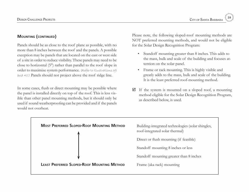
mounting (continued)
Panels should be as close to the roof plane as possible, with no more than 8 inches between the roof and the panels. A possible exception may be panels that are located on the east or west side of a site in order to reduce visibility. These panels may need to be close to horizontal (5°) rather than parallel to the roof slope in order to maximize system performance. (Refer to Illustrations 39
and 40.) Panels should not project above the roof ridge line.
In some cases, flush or direct mounting may be possible where the panel is installed directly on top of the roof. This is less vis-ible than other panel mounting methods, but it should only be used if sound weatherproofing can be provided and if the panels would not overheat.
most preferred sloped-roof mounting method
leAst preferred sloped-roof mounting method
Building-integrated technologies (solar shingles, roof-integrated solar thermal)
Direct or flush mounting (if feasible)
Standoff mounting 8 inches or less
Standoff mounting greater than 8 inches
Frame (aka rack) mounting
Please note, the following sloped-roof mounting methods are NOT preferred mounting methods, and would not be eligible for the Solar Design Recognition Program:
• Standoff mounting greater than 8 inches. This adds to the mass, bulk and scale of the building and focuses at-tention on the solar panel.
• Frame or rack mounting. This is highly visible and greatly adds to the mass, bulk and scale of the building. It is the least preferred roof-mounting method.
þ If the system is mounted on a sloped roof, a mounting method eligible for the Solar Design Recognition Program, as described below, is used.
DESign challEngE ProjEctS

Solar EnErgy SyStEm DESign guiDElinES & Solar rEcognition awarD Program 29
ground-mounted systems
Ground-mounted systems are bolted into the ground and sup-ported by frames. If possible, ground-mounted systems should be installed so that they are not readily visible from public areas. Ground-mounted systems can be well-suited to large hillside lots; however, many hillside locations can be easily seen from areas below. Ground-mounted systems’ designs should be sensitive to this issue. If the ground-mounted system is visible from public locations, try to mount the panels as close as possible to the ground while allowing adequate drainage and preventing vegeta-tion from shading the panels. Provide attractive vegetation to fur-ther “frame” and “soften” the appearance of ground-mounted panels. Remember to locate systems outside of required setbacks and open yard areas. All of the following guidelines should be followed for publicly visible ground-mounted systems.
1. Least visible high-performance location. Locating systems in rear yards is likely to make systems less visible from the street, but some rear-yard systems may be highly visible throughout the neighborhood or other parts of the city. Locate systems toward the bottom of a hill rather than at the top to reduce visibility if feasible.
þ The system is located in the overall least visible location where 85% of optimal system performance can be achieved.
2. Appropriate Array Arrangement.
þ Large ground-mounted arrays are appropriately broken into separate rows or squares.
3. Minimized visual impact from support frames.
3a. Install systems as close to the ground as feasible to match the slope of the hillside. This avoids the need for tall frames and supports. Many slopes in Santa Barbara’s hillside areas are a minimum of 10° (or approximately 20% slope). At this angle, systems can achieve approxi-mately 95% of the optimal system output.
þ The system is installed within 1 foot of the natural ground topography.
OR
3b. Custom-fitted triangular walls can help to hide the frames and supports of systems that are mounted off the ground. Such walls should use earth-tone colors and preferably native, natural materials and should be integrated with surrounding vegetation. Drought-tolerant, preferably native ground-cover landscaping can help to frame ground-mounted systems. Taller screening and landscaping on the north side of panels is encouraged.
þ Frames are hidden with natural material walls or drought-tolerant, preferably native landscaping with a mature height which will not shade the panel.
(Refer to Illustrations 41 and 42 on following page.)

city of Santa BarBara 30
(Illustration 41) This site uses native landscaping to frame the array, helping to integrate it into the site. The panels are also located close to the ground to further reduce their visibility.
(Illustration 42) This array protrudes several feet above the ground with little landscaping to mask the exposed framing system, and making it visible from public areas below.
DESign challEngE ProjEctS

Solar EnErgy SyStEm DESign guiDElinES & Solar rEcognition awarD Program 31
speciAl chAllenge solAr energy system projects: Mission tile, Historic Districts anD structures, anD coMMercial systeMs
speciAl chAllenge cAtegory 1: “mission-style” tile roofs on non-ideAl site conditions
“Mission-style” tile roofs are integral to Santa Barbara’s special character, especially in special design districts like the El Pueblo Viejo District. Avoid placing arrays on publicly visible terra cotta or Mission-style” tile roofs because the dark coloring and smooth finish on solar panels contrast greatly with terracotta colored, detailed tile patterns Also, in Santa Barbara, the contemporary look of solar panels would contrast with the “historic” feel traditional Mission style C-tiles provide. (Refer to Illustrations 43 and 44.)
For this challenging situation, consider alternative, less visible system locations instead such as:
• Ground-mounted systems• Systems on non-tile roof accessory structures (ex; a shed)• An architecturally compatible parapet screening method
to hide the panels on a terra cotta roof without placing the panels on tiles
þ If buildings with Mission-style tile roofs are on site, an innovative solution is used to achieve higher performance without installing the system directly on a publicly visible roof. Guidelines for “Design Challenge” projects are also followed.
(Illustration 43) An array on a terra cota tile roof out-side of the public view, such as this array oriented to-wards a backyard, is appropriate.
(Illustration 44) Dark, flat solar arrays look out of place on publicly visible terra cotta tile because of the contrasting colors.

city of Santa BarBara 32
speciAl chAllenge cAtegory 2: historic districts And structures
Solar energy systems in Historic Districts, on designated Land-marks or on Structures of Merit should not be visible from the public right of way. Some historic buildings in Santa Barbara with Mission Revival or Mediterranean Revival architectural styles have parapets, which can be used to hide solar energy systems. (Refer
to Illustrations 45, 46 and 47.)
Solar system installations should not damage or alter the exterior of historic structures. For panels that are not flat, consider using custom-fitted walls that match the structure to screen system frames and supports.
Building integrated solutions such as photovoltaic shingles, laminates and glazing may be appropriate on historic structures where they are not publicly visible. Depending on system design, historic significance of the host building, and visibility, building integrated technology may sometimes be acceptable on visible portions of historic structures, but this would be evaluated on a case by case basis.
þ The system is not visible from public areas, and only solar technologies which integrate well with historic struc-tures are proposed. Guidelines for “Design Challenge” projects are also followed, as appropriate.
(Illustrations 45, 46 and 47) This historic building at 34 W. Mission Street was once part of the “Flying A Studio,” where many movies were filmed. Its solar panels are completely invisible from the adjacent streets, allowing the building to retain its historic character. The panels are on a flat roof, but they are hidden by the building’s parapet. The panels are organized in a straight line, avoiding vents and skylights. The two panels closest to the parapet are slightly out of alignment with the rest of the panels in order to prevent them from being visible from the street.
DESign challEngE ProjEctS

Solar EnErgy SyStEm DESign guiDElinES & Solar rEcognition awarD Program 33
speciAl chAllenge cAtegory 3: commerciAl systems
Commercial systems tend to be much larger than residential sys-tems and as a result, can be more difficult to shield from public view. Commercial systems need to follow the same guidelines as other systems, as listed above, but special consideration is needed where a large publicly visible system is proposed. Choose an ap-propriate type of system for the building.
most preferred commerciAl system type
leAst preferred commerciAl system type
Systems that are completely hidden from public view by a parapet
PV laminates on sloped metal roofs or PV glazing
PV panels that serve as regularly sized awnings
Publicly visible roof-mounted systems that meet guidelines
Publicly visible roof-mounted systems that do not meet guidelines
commerciAl systems eligible for the solAr design recog-nition progrAm:
• Systems that are completely hidden from public view by a parapet or other means
• PV laminates on sloped metal roofs or PV glazing• PV panels that serve as well designed, regularly sized
awnings• Solar energy systems located on well-designed architec-
turally compatible trellises located in parking lots• Other publicly visible systems that meet the “Design
Challenge” guidelines above
þ A solar energy system eligible for the Solar Design Recog-nition program is proposed. Guidelines for “Design Chal-lenge” program are followed.
(Illustration 48) This commercial solar panel system on the San Francisco “Rosebud Agency building” is mounted flush with the roof behind a parapet system.
city of Santa BarBara 34
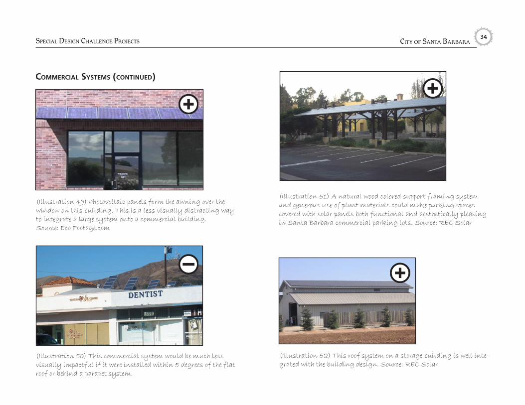
commerciAl systems (continued)
(Illustration 49) Photovoltaic panels form the awning over the window on this building. This is a less visually distracting way to integrate a large system onto a commercial building. Source: Eco Footage.com
SPEcial DESign challEngE ProjEctS
(Illustration 51) A natural wood colored support framing system and generous use of plant materials could make parking spaces covered with solar panels both functional and aesthetically pleasing in Santa Barbara commercial parking lots. Source: REC Solar
(Illustration 52) This roof system on a storage building is well inte-grated with the building design. Source: REC Solar
(Illustration 50) This commercial system would be much less visually impactful if it were installed within 5 degrees of the flat roof or behind a parapet system.

Solar EnErgy SyStEm DESign guiDElinES & Solar rEcognition awarD Program 35
Use this checklist to determine whether a solar energy system project is eligible for the City of Santa Barbara’s Solar Design Recognition Program. A project may be eligible for a Solar En-ergy System Recognition Award if it meets the criteria in one of the following project eligibility areas:
1) Not Publicly Visible Projects;
2) Design Challenge Projects; or
3) Special Challenge Projects.
A project does not need to meet the criteria in more than one of the project eligibility areas in order to receive an award. Staff will make recommendations to City Council regarding solar energy systems which qualify to receive an award through the Solar Design Recognition Program.
not publicly visibleProjects are eligible for a Not Publicly Visible Solar Energy Sys-tem Recognition Award if they meet all of the criteria in either Category 1 or Category 2.
Solar Design Recognition Program Checklist: Solar Energy System Recognition Awards
cAtegory 1: ideAl sites for solAr instAllAtions
¨The solar system is proposed on an ideal high performance solar system site, out of the public view.
cAtegory 2: flAt-roof pAnel systems
¨ The flat-roof panel system successfully uses one of the fol-lowing solutions:
• An architecturally compatible parapet hides the angled system from public view, or
• The system is placed far enough toward the rear of large buildings so the system will not be visible from public areas, or
• If the system is visible, it is mounted at an angle of no more than 5° from the roof surface
¨If the system will be visible from buildings above, the panels are organized into simple, rectangular groups.
design chAllenge project eligibility:

city of Santa BarBara 36
¨An aesthetically appropriate PV glazing design is proposed for a large commercial or industrial project’s atriums, aw-nings, walls or roofs.
¨If the PV glazing is proposed for a residential structure, the design is innovative in nature to achieve an appropriate aesthetic appearance.
building-integrAted solAr thermAl technologies
¨A cement or metal roof is proposed on a commercial non-historic structure.
¨A cement-tile roof is proposed with the system on a single-family structure, where the cement-tile roof would be con-sidered compatible with the neighborhood.
¨A cement-tile roof is proposed in a historic district or on a historic structure if a cement-tile roof is appropriate for the historic district or structure.
design chAllenge cAtegory 2: cArefully designed And
publicly visibleProjects are eligible for a Solar Energy System Recognition award if they meet all of the criteria in either Category 1 or Category 2.
design chAllenge cAtegory 1: building-integrAted technologies
The following types of Building Integrated Technologies are recommended as attractive solar energy system solutions.
photovoltAic shingles or tiles
¨The entire roof face is covered with solar shingles in order to avoid a visual contrast between solar shingles and regular shingles. Or, if not possible, the shingles are installed in an aesthetically appropriate regular shapes of shingles.
photovoltAic lAminAtes
¨An aesthetically appropriate laminate design is proposed for a commercial, industrial, mixed-use or multi-family residential project
¨If the project is proposed for a single-family residential project, the design is innovative in nature to achieve an ap-propriate aesthetic appearance.
photovoltAic glAZing
Solar rEcognition Program EligiBility chEckliSt

Solar EnErgy SyStEm DESign guiDElinES & Solar rEcognition awarD Program 37
mounted pAnel systems
For this category, structure mounted systems must have each box checked for all the design criteria below for award eligibil-ity. Ground mounted systems must meet all three criteria of the ground mounted category.
system siZe
¨The proposed system is no larger than necessary to meet the building’s electricity needs and to compensate for the initial energy used in the home’s construction. Also, reasonable steps have been taken on the site to reduce electricity use (e.g. outdoor lighting fixtures are for safety lighting only and, if a single-family residence, the structure is smaller than 4,000 square feet).
leAst visible high-performAnce locAtion
¨The system is located in the least visible location where at least 85% of optimal system performance can be achieved.
pAnel ArrAngement And design
¨If the system is mounted on a sloped roof, the system is integrated and incorporated into the structure design by following the seven guidelines on pages 22–25 regarding: 1) overall design integration, 2) installation on a single plane roof if feasible, 3) covering as much of a roof face as possible, 4) avoiding array pattern interruptions from rooftop equipment, 5) avoiding creating multiple panel groups, 6) consideration of placement on the lowest edge of a roof if it does not cover the entire roof plane, and 7) coordination of panel materials and framing with roof and/or building colors as feasible.
system infrAstructure screening
¨The proposed system follows guidelines regarding screening frames, supports, equipment and conduits.
frAme color
¨If frames are not blocked from view, colored frames are used to match or complement the roof or building colors.
glAre
¨The proposed system follows the glare guidelines.
mounting
¨If the system is mounted on a sloped roof, an eligible mount-ing method described on pages 26 - 29 is used. Usually, acceptable mounting methods include the top of the panel being located less than 8” from the structure at all points.
ground-mounted systems
¨The system is located in the overall least visible location where 85% of optimal system performance can be achieved.
¨Large ground-mounted arrays are appropriately broken into separate rows or squares.
¨The system is installed within 1 foot of the natural ground topography; OR frames are hidden with natural material walls or drought-tolerant, preferably native landscaping with a mature height which will not shade the panel.

city of Santa BarBara 38Solar rEcognition Program EligiBility chEckliSt
speciAl chAllenge project eligibilityProjects are eligible for a Solar Energy System Recognition Award if they meet the criteria in Category 1, 2 or 3.
cAtegory 1: “mission-style” tile roofs on non-ideAl site conditions
¨If buildings with Mission-style tile roofs are on site, an in-novative solution is used to achieve high system performance without installing the system directly on a publicly visible tile roof. Guidelines for “Design Challenge” projects are also followed.
cAtegory 2: historic districts And structures
¨The system is not visible from public areas, and only solar technologies which integrate well with historic structures are proposed. Guidelines for “Design Challenge” projects are also followed, as appropriate.
cAtegory 3: commerciAl systems
¨A solar energy system type eligible for the Solar Design Recognition Program is proposed. Guidelines for “Design Challenge” projects are followed.
Solar EnErgy SyStEm DESign guiDElinES & Solar rEcognition awarD Program 39
DefinitionsAngle: The shape or space formed by two line segments meeting at one point. In these guidelines, angle is measured in degrees of a circle from a horizontal plane. For example, a panel angled 0° would be horizontal, a panel angled 90° would be vertical, and a panel angled halfway between vertical and horizontal would be at a 45° angle.
Array: A number of solar panels connected together in a single structure. Typically, one array powers one building.
Building-integrated photovoltaics (BIPV): A type of photo-voltaics in which the collectors are integrated into the building construction materials such as the roof or glazing.
Cell, photovoltaic: The most basic unit of a photovoltaic module, where the materials necessary to produce electricity are located. A solar module can have roughly 36 photovoltaic cells.
Collector: The portion of a solar energy system where the sun’s energy is captured into the system. Photovoltaic cells are the collectors in a photovoltaic system. A solar thermal system collector typically refers to an entire box that absorbs the sun’s heat. Many solar thermal system collectors let in heat through a glazed surface and then absorb it inside using special coatings. These collector boxes can measure several feet in width and length, similar to a photovoltaic module.
Conduit: A metal tube housing electrical wires.
Glazing: A covering of transparent or translucent material (typi-cally glass or plastic) used for admitting light.
Grid, electrical: An electrical utility distribution network.
Grid-connected: Connected to the electrical grid. Refers to solar electric systems that can transfer the power they produce to the grid.
Inverter: A piece of electrical equipment that converts DC (direct current) power produced by a photovoltaic array to AC (alternat-ing current) power used in residences and businesses.
Module: An encapsulated panel containing a number of electri-cally connected photovoltaic cells.
Net energy metering: The practice of crediting a homeowner’s electricity bill for surplus power produced by a solar energy sys-tem and exported to the electricity grid.
Panel: Often used interchangeably with “module,” but can also refer to a row of one or more modules.
Parapet: A low wall along the edge of a roof, commonly used in Spanish, Italianate, Mission Revival and Neo-Classical archi-tectural styles and on commercial buildings.

city of Santa BarBara 40
Performance, system: The energy output of a solar energy system.
Photovoltaic: Capable of producing electricity from light.
Public area: Any publicly owned property, including public sidewalks, streets, trails, parks, beaches and plazas.
Roof pitch: The angle or slope of the roof. Often expressed in the units of vertical rise to 12 units of horizontal run.
Roof plane: A single, uniform roof surface with equal pitch throughout.
Solar access: Ability of a building or collector to receive light and heat from the sun.
Solar energy: Energy from the sun, including heat and electric-ity generated using the sun’s radiant energy. This is distinguished from energy derived from fuels or from the action of wind or water.
Solar energy system: A system, such as a photovoltaic or solar thermal system, that uses the sun’s energy to produce electricity or heat.
Solar hot water system: A system that uses the sun’s energy to heat water.
Solar thermal system: A system that uses the sun’s energy to produce heat. Solar hot water systems, solar space heating sys-tems and solar space cooling systems are all examples of solar thermal systems.
Style, architectural: A way to classify architecture based on the appearance and character of a building’s design and construc-tion.
Yard, front: The open space, unoccupied and unobstructed from the ground upward, extending across the full width of the lot between the front lot line and the nearest wall of any building.
Yard, open: An open space, on a lot or parcel of land, unoccu-pied and unobstructed from the ground upward, which does not contain any of the following: (a) cut or fill sloped greater than one foot (1’) rise or fall in five feet (5’) of horizontal distance; (b) portion of a front yard; (c) paving or other surfacing designed for use by motor vehicles or trailers.
Yard, rear: The open space, unoccupied and unobstructed from the ground upward, extending between the rear lot line and the nearest wall of any building.