solar marine lanterns -...
TRANSCRIPT

Version 4.0
SL-C500 & SL-C600Solar Marine Lanterns
Installation & Service Manual

Version No. Description Date Approved3.2 Update Manual August 2010 K. Paton4.0 Update Spec Table & Remove SLC400 May 2012 J. Dore5.0 Lighthead update (SL-155) July 2015 Y. Chambers

Latest products and information available at www.sealite.com3
SL-C500 & SL-C600 Solar Marine Lanterns
Introduction ....................................................................................................... Page 4Operating Principle .......................................................................................... Page 4Technology ........................................................................................................ Page 4SL-C500 Model .................................................................................................. Page 5SL-C600 Model .................................................................................................. Page 8Product Components .................................................................................... Page 11Programming the Lantern: PC Configuration Tool ..................................... Page 12 Info Tab ...................................................................................................... Page 16 Operation mode Tab ................................................................................. Page 17 Flash Code ................................................................................................ Page 19 Intensity ..................................................................................................... Page 20 Sensors ...................................................................................................... Page 21 AIS Report ................................................................................................. Page 23Programming the Lantern: IR Programmer ................................................. Page 24 Sealite IR Controller / Universal Remote Compatibility ........................ Page 24 IR Programmer Functions ........................................................................ Page 25 Test Mode / Configure ........................................................................... Page 25 Normal Operation .................................................................................. Page 25 Read ...................................................................................................... Page 25 Flash Code ............................................................................................ Page 26 Flash Code Numbers ............................................................................ Page 26 Intensity ................................................................................................. Page 26 Battery Status ........................................................................................ Page 27 Lux ........................................................................................................ Page 27 Error / Acknowledge Indication .............................................................. Page 28 Configuration Settings ........................................................................... Page 28 Operational Mode (Advanced Users) .................................................... Page 29Lantern Testing ............................................................................................... Page 30Installation .......................................................................................................Page 31Optional GPS Synchronisation ..................................................................... Page 32Optional GSM Monitoring & Control System ............................................... Page 33Maintenance & Servicing ............................................................................... Page 34Trouble Shooting ............................................................................................ Page 35Appendix: Flash Codes .................................................................................. Page 36 Sealite LED Light Warranty ........................................................................... Page 42
Table of Contents
Latest products and information available at www.sealite.com4
SL-C500 & SL-C600 Solar Marine Lanterns
IntroductionCongratulations! By choosing to purchase a Sealite lantern you have become the owner of one of the most advanced LED marine lanterns in the world.Sealite Pty Ltd has been manufacturing lanterns for over 25 years, and particular care has been taken to ensure your lantern gives years of service.As a commitment to producing the highest quality products for our customers, Sealite has been independently certified as complying with the requirements of ISO9001:2008 quality management system.Sealite lanterns comply with requirements of the US Coast Guard in 33 CFR part 66 for Private Aids To Navigation.By taking a few moments to browse through this booklet, you will become familiar with the versatility of your lantern, and be able to maximise its operating function.
Operating PrincipleThe solar module of the lantern converts sunlight to an electrical current that is used to charge the battery. The battery provides power to operate the lantern at night. The flasher unit has very low current requirements. A microprocessor drives an array of ultra bright LED’s through a DC/DC converter, which enables the LED’s to operate within the manufacturer’s specifications. The battery is protected from over-charging within the circuit to ensure maximum battery life. On darkness, the microprocessor will initiate a program check and after approximately 1 minute begin flashing to the set code
TechnologySealite is the world’s fastest growing manufacturer of marine aids to navigation. We employ leading mechanical, optical, hardware & software engineers to create innovative products to service the needs of our customers worldwide, and offer the widest range of solar-powered LED lanterns in the marketplace. ElectronicsSealite employs leading in-house electronic engineers in the design and development of software and related circuitry. All individual electronic components are sourced directly by Sealite procurement staff ensuring that only the highest quality components are used in our products.
LED TechnologyAll marine lanterns use the latest advancements in LED (Light Emitting Diode) technology as a light source. The major advantage of LED’s over traditional light sources is well established in that they typically have an operational life in excess of 100,000 hours, resulting in substantial savings to maintenance and servicing costs.
Precision Construction Commitment to investing in the design and construction of injection-moulded parts including optic lenses, light bases and a range of other components ensures that all Sealite products are of a consistent & superior quality.
Optical PerformanceSealite manufactures a range of marine LED lenses moulded from multi-cavity dies. Complex shapes such as the SL70, BargeSafe™ and 16-segment multi-focus lenses are a testament to the company’s superior in-house lens manufacturing capabilities and outstanding optical performance.
Award-winning, Patented Technology Several United States and Australian patent registrations are held on Sealite’s range of innovative designs, with other regional patents pending in Canada, United Kingdom and Europe.

Latest products and information available at www.sealite.com5
SL-C500 & SL-C600 Solar Marine Lanterns
SL-C500 ModelThe SL-C500 is a completely self-contained 5–12NM Solar LED Marine Lantern designed for a range of low-maintenance applications.The light boasts a large internal battery compartment, a SL-155 Series LED light-head and 4 premium-grade 10 watt solar modules mounted to collect sunlight at all angles.The SL-C500 is moulded from UV-stabilised, virgin polyethylene, providing enormous impact and weather resistance, in addition to high visibility IALA colours.The user-friendly, 2-piece design allows the lantern to be opened for convenient battery inspection or replacement whilst the base remains fixed to the supporting structure.
Advanced PC or IR Programming Sealite’s convenient PC Configuration Tool or IR programmer allows a host of features to be user set including; •Multipleintensitysettings• 310flashsettingsincludingcustomcharacter• Automaticeffectiveintensityadjustment• Adjustableon/offluxlevels• Lowbatterythreshold•GPSsynchronisationoffset• Alarmconditions
SL-155 Series light head
Rotationally-moulded, UV-stabilised, virgin polyethylene body
Bird deterrent spikes
4 x 10watt (40watts total)
multicrystalline solar modules, ensuring
maximum light collection to charge
the battery
Internal 55Ah battery

Latest products and information available at www.sealite.com6
SL-C500 & SL-C600 Solar Marine Lanterns
• S
pe
cifi
ca
tion
s su
bje
ct t
o c
ha
ng
e o
r va
riatio
n w
itho
ut n
otic
e
* Su
bje
ct t
o s
tan
da
rd te
rms
an
d c
on
diti
on
s†
Inte
nsi
ty s
ett
ing
su
bje
ct t
o s
ola
r ava
ilab
ility
SPECIFICATIONS•* SL-C500Light CharacteristicsLight Source SL-155-2.5D/5D/10D lantern Available Colours Red, Green, White, YellowTypical Maximum Intensity (cd)† Refer to Typical Maximum Intensity Table for SL-155 Series LanternsVisible Range (NM) AT @ 0.74: 5–12
AT @ 0.85: 6.3–17.4Horizontal Output (degrees) 0o - 360oVertical Divergence (degrees) 2.5o, 5o or 10oAvailable Flash Characteristics Up to 310 including 256 IALA recommended, & 1 custom Intensity Adjustments User adjustableLED Life Expectancy (hours) >100,000
Electrical CharacteristicsCurrent Draw (mA) Refer to Sealite Power CalculatorPower (W) Refer to Sealite Power CalculatorCircuit Protection Polarity protectedNominal Voltage (VDC) 12Autonomy (days) >20 (14 hour darkness, 12.5% duty cycle)Temperature Range -40 to 80°C
Solar CharacteristicsSolar Module Type MulticrystallineOutput (watts) 40 (4 x 10watt)Charging Regulation Microprocessor controlled
Power SupplyBattery Type Gel SLABattery Capacity (Ah) 55Nominal Voltage (V) 12
Physical CharacteristicsBody Material Rotationally-moulded UV-stabilised virgin polyethyleneLens Material UV-stabilised acrylicLens Diameter (mm/inches) From 171 / 6¾Lens Design Multiple LED opticMounting 4 x 11mm mounting holesHeight (mm/inches) From 675 / 26½Width (mm/inches) 560 / 22Mass (kg/lbs) From 23 / 50.7Product Life Expectancy Up to 12 years
CertificationsCE EN61000-6-3:1997. EN61000-6-1:1997IALA Signal colours compliant to IALA E-200-1Quality Assurance ISO9001:2008Waterproof IP68 light-head
Intellectual PropertyTrademarks SEALITE® is a registered trademark of Sealite Pty Ltd
Warranty * 3 years
Options Available • SL-125 Series Lantern• 200mm bolt pattern mounting plate • GPS Synchronisation • AIS Remote Monitoring • GSM Monitoring & Control System • RS232/422/485 Port• General purpose inputs (2) & outputs (2)

Latest products and information available at www.sealite.com7
SL-C500 & SL-C600 Solar Marine Lanterns
Figure 1. SL-C500
Latest products and information available at www.sealite.com8
SL-C500 & SL-C600 Solar Marine Lanterns
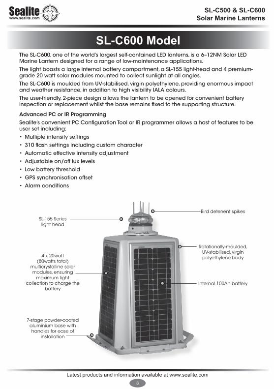
SL-C600 ModelThe SL-C600, one of the world’s largest self-contained LED lanterns, is a 6–12NM Solar LED Marine Lantern designed for a range of low-maintenance applications.The light boasts a large internal battery compartment, a SL-155 light-head and 4 premium-grade 20 watt solar modules mounted to collect sunlight at all angles.The SL-C600 is moulded from UV-stabilised, virgin polyethylene, providing enormous impact and weather resistance, in addition to high visibility IALA colours.The user-friendly, 2-piece design allows the lantern to be opened for convenient battery inspection or replacement whilst the base remains fixed to the supporting structure.
Advanced PC or IR Programming Sealite’s convenient PC Configuration Tool or IR programmer allows a host of features to be user set including; •Multipleintensitysettings• 310flashsettingsincludingcustomcharacter• Automaticeffectiveintensityadjustment• Adjustableon/offluxlevels• Lowbatterythreshold•GPSsynchronisationoffset• Alarmconditions
SL-155 Series light head
4 x 20watt (80watts total)
multicrystalline solar modules, ensuring
maximum light collection to charge the
battery
7-stage powder-coated aluminium base with handles for ease of
installation
Bird deterrent spikes
Rotationally-moulded, UV-stabilised, virgin polyethylene body
Internal 100Ah battery

Latest products and information available at www.sealite.com9
SL-C500 & SL-C600 Solar Marine Lanterns
• S
pe
cifi
ca
tion
s su
bje
ct t
o c
ha
ng
e o
r va
riatio
n w
itho
ut n
otic
e
* Su
bje
ct t
o s
tan
da
rd te
rms
an
d c
on
diti
on
s†
Inte
nsi
ty s
ett
ing
su
bje
ct t
o s
ola
r ava
ilab
ility
SPECIFICATIONS•* SL-C600Light CharacteristicsLight Source SL-155-2.5D/5D/10D lantern Available Colours Red, Green, White, YellowTypical Maximum Intensity (cd)† Refer to Typical Maximum Intensity Table for SL-155 Series LanternsVisible Range (NM) AT @ 0.74: 6–12
AT @ 0.85: 7.8–17.4Horizontal Output (degrees) 0o - 360oVertical Divergence (degrees) 2.5o, 5o or 10oAvailable Flash Characteristics Up to 310 including 256 IALA recommended, & 1 custom Intensity Adjustments User adjustableLED Life Expectancy (hours) >100,000
Electrical CharacteristicsCurrent Draw (mA) Refer to Sealite Power CalculatorPower (W) Refer to Sealite Power CalculatorCircuit Protection Polarity protectedNominal Voltage (VDC) 12Autonomy (days) >20 (14 hour darkness, 12.5% duty cycle)Temperature Range -40 to 80°C
Solar CharacteristicsSolar Module Type MulticrystallineOutput (watts) 80 (4 x 20watt)Charging Regulation Microprocessor controlled
Power SupplyBattery Type Gel SLABattery Capacity (Ah) 100Nominal Voltage (V) 12
Physical CharacteristicsBody Material Rotationally-moulded UV-stabilised virgin polyethyleneLens Material UV-stabilised acrylicLens Diameter (mm/inches) From 171 / 6¾Lens Design Multiple LED opticMounting 4 x 11mm mounting holesHeight (mm/inches) From 813/ 32Width (mm/inches) 665 / 261/4
Mass (kg/lbs) From 50 / 110Product Life Expectancy Up to 12 years
CertificationsCE EN61000-6-3:1997. EN61000-6-1:1997IALA Signal colours compliant to IALA E-200-1Quality Assurance ISO9001:2008Waterproof IP68 light-head
Intellectual PropertyTrademarks SEALITE® is a registered trademark of Sealite Pty Ltd
Warranty * 3 years
Options Available • SL-125 Series Lantern• 200mm bolt pattern mounting plate • GPS Synchronisation • AIS Remote Monitoring • GSM Monitoring & Control System • RS232/422/485 Port• General purpose inputs (2) & outputs (2)

Latest products and information available at www.sealite.com10
SL-C500 & SL-C600 Solar Marine Lanterns
Figure 2. SL-C600

Latest products and information available at www.sealite.com11
SL-C500 & SL-C600 Solar Marine Lanterns
The following components come standard with each lantern:-• SL-C500 or SL-C600 lantern • IR Programmer• Installation & service manual
These components are securely packaged within foam in a carton, and shipped to you.
PLEASE NOTE: The programming cable provided is suitable for use with PC’s. If you require connection to your notebook/laptop, a Serial Port to USB cable may need to be purchased.
Please check that ALL of these components are included with your order, and contact your Sealite representative as soon as possible if anything is missing.
Product Components

Latest products and information available at www.sealite.com12
SL-C500 & SL-C600 Solar Marine Lanterns
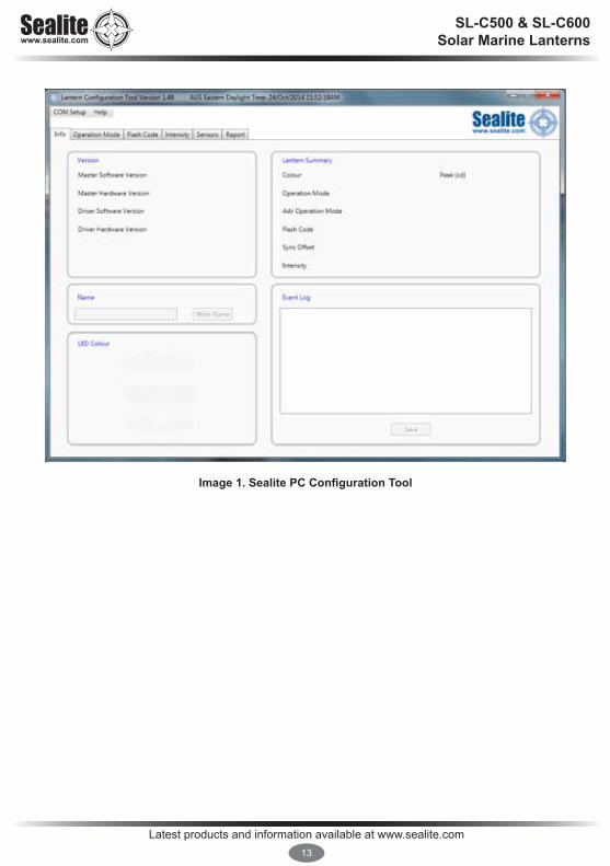
PC Configuration ToolThe lantern is pre-programmed to the customer’s specific requirements for convenience (eg. flash, intensity setting etc). The SL-155 Series are extremely intelligent lanterns with a number of features which can be programmed directly via a user-friendly computer program (as supplied on USB drive with every lantern). To change/update the settings of your lantern, please read the following instructions.
1. Run the Programming Software The programming software may be run directly from the USB drive provided, or you may copy the software to your computer hard-drive for future use.
Running the Programming Software from the USB Drive• Connect the USB drive to your computer• Navigate to the USB drive folder & double-click the file called “LanternConfig.exe”. A new window
will appear displaying the PC Configuration Tool.
Saving the Programming Software to Computer Hard-Drive• Connect the USB drive to your computer• Navigate to the USB drive folder• Copy the file called “LanternConfig.exe” and the “.dll” files• Navigate to the hard-drive location where you would like to save this program, and then right-
mouse-click and select “paste”. A copy of the programming software will now be saved to your computer hard-drive (to add the programmer to your computer desktop for ease of future access, right-mouse-click and select “Send to desktop”)
• Double-click the file called “LanternConfig.exe”. A new window will appear displaying the PC Configuration Tool
PLEASE NOTE: other documents have been saved on the USB drive for your information & convenience including the latest product specifications sheet and an electronic version of the installation and service manual. You may wish to view these documents to read more about the innovative features and benefits of the SL-155 Series of lanterns.
IMPORTANT: the Sealite PC Configuration Tool is designed for Windows Platforms only.
Programming the Lantern
Latest products and information available at www.sealite.com13
SL-C500 & SL-C600 Solar Marine Lanterns
Image 1. Sealite PC Configuration Tool
Latest products and information available at www.sealite.com14
SL-C500 & SL-C600 Solar Marine Lanterns
2. Connect the SL-155 Series Lantern to a Power Source & the Computer Now that the programming software has been run, you will need to connect the lantern to your computer & power supply so that it can receive programming commands.
Once connection is made, the software automatically determines the colour and preprogrammed settings of the lantern.
Connecting the Lantern to a Power Source Option 1: Battery• Connect the blue negative wire of the lantern to the battery negative terminal • Connect the brown positive wire of the lantern to the battery positive terminal
Option 2: 12V Power Supply• Connect the blue negative wire of the lantern to the power supply negative termainal • Connect the brown positive wire of the lantern to the power supply positive terminal
CAUTION: to avoid personal injury do not position the lantern at eye level.
Connecting the Lantern to the Computer • Plug the Bulgin connector end of the the programming cable into the lantern PC Programming
Port, and the serial port end of the cable into your computer serial/communication port (RS232-E)
PLEASE NOTE: The programming cable provided is suitable for use with desktop PC’s. If you require connection to your notebook/laptop, a Serial Port to USB cable may need to be purchased.
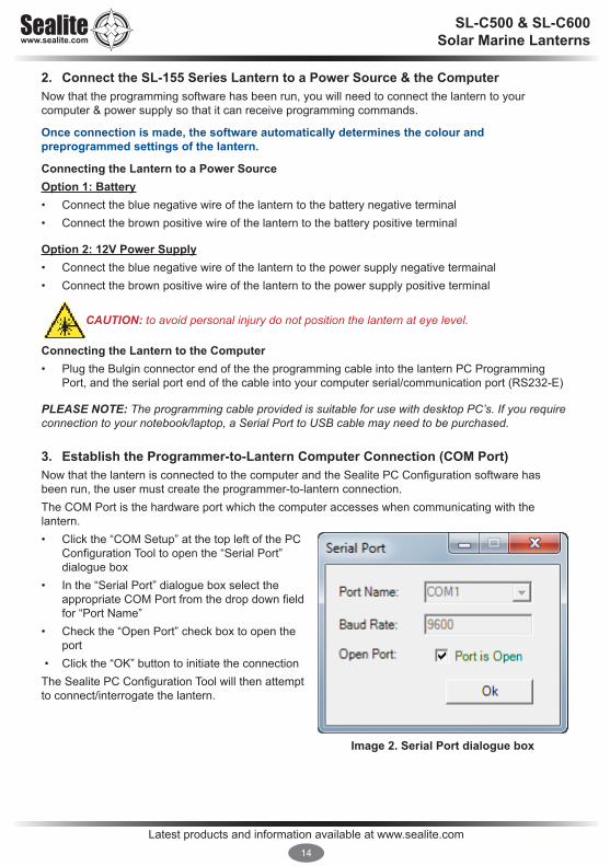
3. Establish the Programmer-to-Lantern Computer Connection (COM Port) Now that the lantern is connected to the computer and the Sealite PC Configuration software has been run, the user must create the programmer-to-lantern connection. The COM Port is the hardware port which the computer accesses when communicating with the lantern. • Click the “COM Setup” at the top left of the PC
Configuration Tool to open the “Serial Port” dialogue box
• In the “Serial Port” dialogue box select the appropriate COM Port from the drop down field for “Port Name”
• Check the “Open Port” check box to open the port
• Click the “OK” button to initiate the connection The Sealite PC Configuration Tool will then attempt to connect/interrogate the lantern.
Image 2. Serial Port dialogue box

Latest products and information available at www.sealite.com15
SL-C500 & SL-C600 Solar Marine Lanterns
Correct Connection Established If the connection is established data about the lantern configuration will appear on the “Info” tab under the headings “Version” & “Lantern Summary” (eg. Lantern Colour, Flash Code, Intensity etc).
Connection NOT EstablishedIf the connection is not available, the Sealite PC Configuration Tool will not display any lantern specific information under the headings “Version” & “Lantern Summary”. If this error occurs, please check the following:• Reconnect the lantern to the computer • Check that the lantern power supply has sufficient charge (eg. battery is charged), and then
reconnect it to the lantern• Re-run the Sealite PC Configuration Tool and follow the information in step 3. The connection
should now become established.
The Sealite lantern is now ready to be programmed to your specific requirements.
Image 3. Sealite Configuration Tool “Info” tab – showing COM Port connection established, Version & Lantern Summary information

Latest products and information available at www.sealite.com16
SL-C500 & SL-C600 Solar Marine Lanterns
Provides a summary of the lantern configuration settings, hardware and software versions, and event log.
Version Is an information panel that identifies the Lantern’s internal electronic hardware and firmware versions.
Lantern SummaryIs an information panel that displays a summary of the key lantern settings: colour, operation mode, Peak Intensity setting, Advance Operational Mode, Flash Code, Flash Sync offset and Intensity setting. Refer to the Information, Operation Mode Flash Code, and Intensity Tabs for a description of these parameters.
NameA user defined name, comprising alphanumeric characters (and -, $, #,@) can be typed into dialogue box and by pressing and stored within the lantern’s non-volatile memory by pressing the ‘Write Name’ button.
LED ColourA generic picture of the lantern model and colour that the software tool is communicating with is displayed in this panel.
Event LogDisplays the number of alarm event recorded by the lantern firmware. Possible alarms (flat battery, low battery, LED failure, high temperature). All alarm events are recorded irrespective of whether the lantern has been configured to respond to an alarm.
Info Tab

Latest products and information available at www.sealite.com17
SL-C500 & SL-C600 Solar Marine Lanterns
Defines the lanterns mode of operation of which there are four possibilities:
Operational ModeStandbyThe lantern is configured in a minimum current state in which the LEDs are always off and the internal GPS (if installed) is disabled.
Always OnThe daylight sensor is disabled and the lantern operates according to the set flash character and intensity levels.
Dusk till DawnThe daylight sensor is monitored and the lantern will only operate at night time.
Time after duskLantern only turns on after dusk and for a defined period of time (hours)
Operation mode Tab

Latest products and information available at www.sealite.com18
SL-C500 & SL-C600 Solar Marine Lanterns
Adv Op ModeThis is an advanced user mode and typically only used if the lantern is to be used as special navigational aid such as emergency wreck mark.
AllDefault setting. All leds are operate in unison and configured by the Operation Mode Flash Code, and Intensity Tabs.
Bank 1 (Visible) One half (180deg) bank of LEDs are only enabled whilst the other half are disabled.
Bank 2 (IR)One half (180deg) bank of LEDs are only enabled whilst the other half are disabled.
AlternatingAdjacent LED, alternate their on/off state based upon the intensity and flash character settings. For example, ship wreck marks.
Top tierTop tier of the lanterns is set to steady on. With the intensity levels selected to be set to either 25% or 50% of the flashing intensity. ResetWithin the lantern, set at the factory, all the parameters are return to default. The event log is remains unchanged.
Latest products and information available at www.sealite.com19
SL-C500 & SL-C600 Solar Marine Lanterns
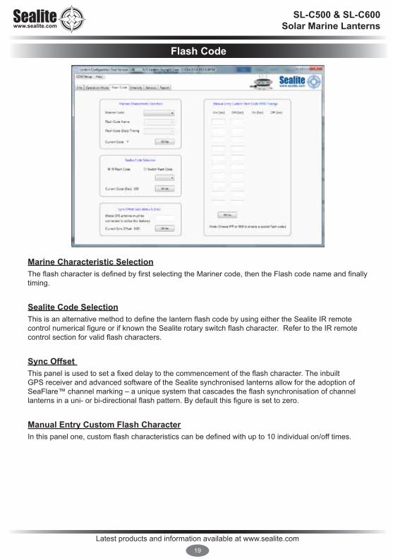
Marine Characteristic SelectionThe flash character is defined by first selecting the Mariner code, then the Flash code name and finally timing.
Sealite Code SelectionThis is an alternative method to define the lantern flash code by using either the Sealite IR remote control numerical figure or if known the Sealite rotary switch flash character. Refer to the IR remote control section for valid flash characters.
Sync Offset This panel is used to set a fixed delay to the commencement of the flash character. The inbuilt GPS receiver and advanced software of the Sealite synchronised lanterns allow for the adoption of SeaFlare™ channel marking – a unique system that cascades the flash synchronisation of channel lanterns in a uni- or bi-directional flash pattern. By default this figure is set to zero.
Manual Entry Custom Flash CharacterIn this panel one, custom flash characteristics can be defined with up to 10 individual on/off times.
Flash Code

Latest products and information available at www.sealite.com20
SL-C500 & SL-C600 Solar Marine Lanterns
Lantern intensityThe lantern intensity level can be set by either by defining the operating range of the lantern (in Nautical miles) or by entering a desired peak candela or a percentage of maximum peak intensity level.
If Schmidt Clausen is applied is selected, the lantern will automatically adjust the intensity level based up on the entered range and flash character setting. The intensity level is automatically each time a new range (NM) or flash character is written to the lantern.
If a intensity level is selected that is beyond the specification of the lantern, the entered figure will be displayed in in red coloured text, and the lantern will configure the lantern to its maximum.
Note: The lanterns has been designed with a dynamic intensity limit. This limit will come into effect if you select a flash characteristic with a heavy duty cycle (> 28.125%) and set a very high intensity.
Under these conditions the lantern will automatically reduce its intensity so that it is operating within the thermal design window. Thus giving you years of operation without any noticeable degrade in light output. This intensity limit will not be reached for the majority of applications.
The peak power limit for the SL-155-5D and Sl-155-10D lanterns has been set to 28.125%. There are 69 flash codes in the base table of 256 that will have an intensity cap.
The peak power limit for the SL155-2 has been set to 34.375%. There are 51 flash codes in the base table of 256 that will have an intensity cap.
Intensity
Latest products and information available at www.sealite.com21
SL-C500 & SL-C600 Solar Marine Lanterns
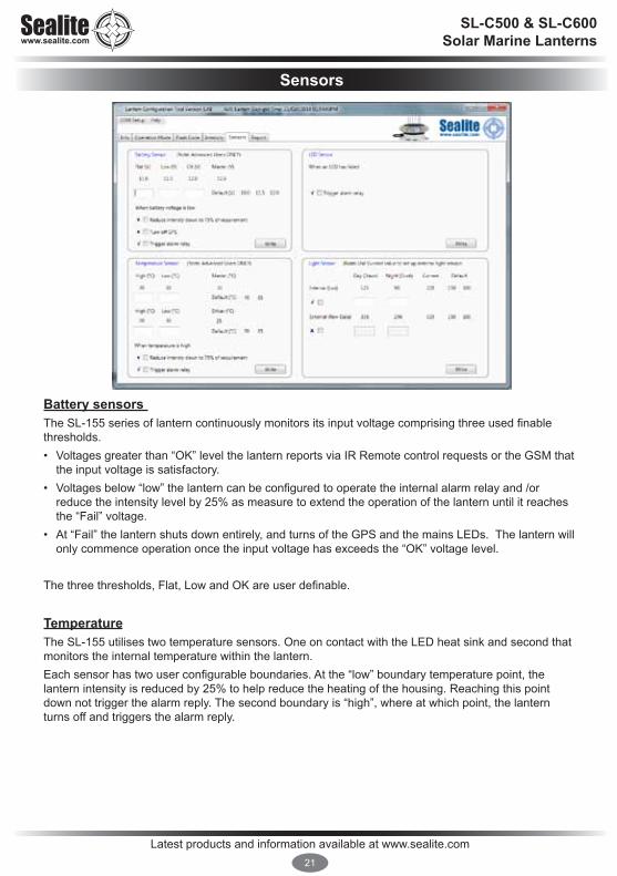
Battery sensors The SL-155 series of lantern continuously monitors its input voltage comprising three used finable thresholds. • Voltages greater than “OK” level the lantern reports via IR Remote control requests or the GSM that
the input voltage is satisfactory.• Voltages below “low” the lantern can be configured to operate the internal alarm relay and /or
reduce the intensity level by 25% as measure to extend the operation of the lantern until it reaches the “Fail” voltage.
• At “Fail” the lantern shuts down entirely, and turns of the GPS and the mains LEDs. The lantern will only commence operation once the input voltage has exceeds the “OK” voltage level.
The three thresholds, Flat, Low and OK are user definable.
TemperatureThe SL-155 utilises two temperature sensors. One on contact with the LED heat sink and second that monitors the internal temperature within the lantern.Each sensor has two user configurable boundaries. At the “low” boundary temperature point, the lantern intensity is reduced by 25% to help reduce the heating of the housing. Reaching this point down not trigger the alarm reply. The second boundary is “high”, where at which point, the lantern turns off and triggers the alarm reply.
Sensors

Latest products and information available at www.sealite.com22
SL-C500 & SL-C600 Solar Marine Lanterns
LED SensorBuilt into the SL-155 lantern, is a closed loop monitoring system for each LED within the lantern. In the event of a single LED failure is detected, the lantern can be configured to trigger the internal alarm relay which in turn can be connected eternally to trigger other devices such a redundant light source.
Light SensorThe SL-155 lantern has its own internal light sensor and whose day/night thresholds are defined in LUX. These levels can be customised by entering in separate dusk and dawn values as a measure of LUX.
If optioned, an external light sensor such as Light dependant resistor or photodiode can be electrically connected to the SL-155.

Latest products and information available at www.sealite.com23
SL-C500 & SL-C600 Solar Marine Lanterns
Lantern StatusThis panel display the Lantern’s AIS message that is outputted via the serial communications port every 10seconds. Typically this message is processed by an externally installed AIS module, however by itself as is quick summary of the lantern operating status. This detail is also displayed on the INFO tab.
AIS Report

Latest products and information available at www.sealite.com24
SL-C500 & SL-C600 Solar Marine Lanterns
The IR programmer is used to communicate with Sealite lighting products that have an IR sensor fitted. The remote control is used for the following functions:• Flash Code: read the current flash code, configure a new flash code.• Lamp Intensity: read the current lamp intensity, configure a new intensity
level.• Ambient Light Thresholds: read the current light thresholds, configure new
ambient light thresholds.• Perform a battery health check.On receiving a valid key signal from the IR Programmer, the light will flash once. The user should wait until the light responds to each keypress before pressing another key. If there is no response to the keypress after 3 seconds, it has not been detected by the light and the key can be pressed again.If an invalid key is detected, the light will flash quickly 5 times. In this case, the command will have to be restarted.
T/CT/C
Read Lux
Flash Code Intensity Battery Status
Test / Con�gure
R L
FC I B
3
4 5 6
7 8 9
0
1 2
IR Programmer
Sealite IR Programmer / Universal Remote CompatibilityIf you lose your Sealite IR Programmer, the following Universal Remote Controller has been tested for compatibility: RCA Type RCR312WR programmed for Phillips TV Type Code 10054
Sealite Key Universal Remote Key
T Power1 12 23 34 45 56 67 78 89 90 0R Channel+L Mute
FC Volume+I Volume-B Channel-

Latest products and information available at www.sealite.com25
SL-C500 & SL-C600 Solar Marine Lanterns
Test Mode / Configure
Pressing the T/C button for upto 5 seconds places the light in Test Mode. The light will flash once in response to the T/C button being pressed and then turn off.
T/CT/C
R L
FC I B
3
4 5 6
7 8 9
0
1 2
Normal OperationThe light will return to normal operation once it has not detected a valid key press for 30 seconds. The light will flash once to indicate it is returning to normal operation.
ReadPressing the Read followed by one of the configuration keys shall cause the light to flash the configured value.Example Key Sequences:
The light flashes the ‘IR Remote’ number belonging to the currently set Flash Code. Refer to the Flash Code tables to match the ‘IR Remote’ flash number to the Flash Code.
The light flashes the current intensity setting: 1 flash for 25%, 2 for 50%, 3 for 75% and 4 for 100%.
The light flashes the current battery status.
The light flashes the sunset level in Lux, followed by a 2 second gap, followed by the sunrise level. Levels are in the range of 1 to 5.
T/CT/C
R L
FC I B
3
4 5 6
7 8 9
0
1 2T/CT/C
R L
FC I B
3
4 5 6
7 8 9
0
1 2T/CT/C
R L
FC I B
3
4 5 6
7 8 9
0
1 2
T/CT/C
R L
FC I B
3
4 5 6
7 8 9
0
1 2T/CT/C
R L
FC I B
3
4 5 6
7 8 9
0
1 2
T/CT/C
R L
FC I B
3
4 5 6
7 8 9
0
1 2
T/CT/C
R L
FC I B
3
4 5 6
7 8 9
0
1 2
T/CT/C
R L
FC I B
3
4 5 6
7 8 9
0
1 2
T/CT/C
R L
FC I B
3
4 5 6
7 8 9
0
1 2T/CT/C
R L
FC I B
3
4 5 6
7 8 9
0
1 2T/CT/C
R L
FC I B
3
4 5 6
7 8 9
0
1 2T/CT/C
R L
FC I B
3
4 5 6
7 8 9
0
1 2
IR Programmer Functions
Latest products and information available at www.sealite.com26
SL-C500 & SL-C600 Solar Marine Lanterns
Intensity
This function sets the light intensity and is automatically calculated by user selecting the required operational range of the lantern.
writes the range in nautical miles (0–9) where x represents the range
writes the range in nautical miles (0–32) where x represents the range
A range value from 6 to 13NM is valid however the maximum allowable range is dependent on the lantern’s vertical divergence, LED colour and flash character. Using the selected operational range and current flash character, the lantern uses the Schmidt-Clausen Method, as described in IALA E200-4 to determine the peak intensity.If the flash character is changed, the peak intensity is automatically adjusted.
T/CT/C
R L
FC I B
3
4 5 6
7 8 9
0
1 2
L T/CT/Cx
T/CT/C
R L
FC I B
3
4 5 6
7 8 9
0
1 2
T/CT/C
R L
FC I B
3
4 5 6
7 8 9
0
1 2
Flash Code
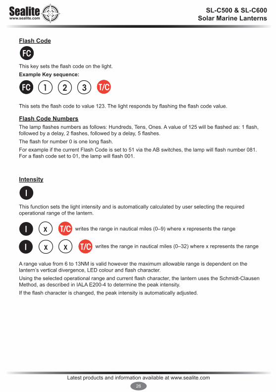
This key sets the flash code on the light.Example Key sequence:
This sets the flash code to value 123. The light responds by flashing the flash code value.
Flash Code NumbersThe lamp flashes numbers as follows: Hundreds, Tens, Ones. A value of 125 will be flashed as: 1 flash, followed by a delay, 2 flashes, followed by a delay, 5 flashes. The flash for number 0 is one long flash.For example if the current Flash Code is set to 51 via the AB switches, the lamp will flash number 081. For a flash code set to 01, the lamp will flash 001.
T/CT/C
R L
FC I B
3
4 5 6
7 8 9
0
1 2
T/CT/C
R L
FC I B
3
4 5 6
7 8 9
0
1 2
T/CT/C
R L
FC I B
3
4 5 6
7 8 9
0
1 2
T/CT/C
R L
FC I B
3
4 5 6
7 8 9
0
1 2
L T/CT/Cx
T/CT/C
R L
FC I B
3
4 5 6
7 8 9
0
1 2
T/CT/C
R L
FC I B
3
4 5 6
7 8 9
0
1 2
L T/CT/Cx

Latest products and information available at www.sealite.com27
SL-C500 & SL-C600 Solar Marine Lanterns
Lux
This key sets the ambient light threshold levels.The format is
Where ‘x’ is the desired setting from the table below.
There are 5 programmable lux levels which are set together for the sunset and sunrise transitions.
Example key sequence:
Assume the current Lux settings are at the factory preset values of 2.This sets the ambient light level to be lower than the default 100 lux. The light will turn on when its surroundings are darker. The light responds by acknowledgement with a long flash.
Level Sunset (Dusk)
Sunrise (Dawn)
1 64 1002* 100 1503 150 2404 240 3705 370 600
* Default / Factory Preset
L T/CT/Cx
L T/CT/Cx
L T/CT/C1
T/CT/C
R L
FC I B
3
4 5 6
7 8 9
0
1 2
T/CT/C
R L
FC I B
3
4 5 6
7 8 9
0
1 2
T/CT/C
R L
FC I B
3
4 5 6
7 8 9
0
1 2
T/CT/C
R L
FC I B
3
4 5 6
7 8 9
0
1 2
Battery Status
This function reads the battery status. The response from the light is High Voltage: 4 flashes, Good Voltage: 3 flashes, Low Voltage 2 flashes, Cutoff Voltage or below: 1 flash.Example Key sequence:

Latest products and information available at www.sealite.com28
SL-C500 & SL-C600 Solar Marine Lanterns
Error / Acknowledge IndicationIf the key sequence is invalid, or an out of bounds value is attempted to be set, the light flashes 5 times for 1 second. (The command then needs to be sent from the start.)Example key sequence: (Set the intensity level to 5 – undefined.)
The light flashes 5 times for 1 second.When a key sequence has been entered successfully the light will respond acknowledgement with a long 1 second flash.
Configuration SettingsThe intensity and flash codes can be changed using the switches on the lamp circuit board or with the IR Remote Control. The lamp intensity and flash code settings are set to the last detected change, carried out with the IR Remote Control or by changing the switch positions.
Example #1: If the intensity is set at 100% with the intensity switches, and is then set to 50% using the IR Remote Control, the intensity setting will change to 50%. If the intensity is then set to 75% using the switches, the new intensity value will be 75%.In order to change intensity settings using the IR Remoter Control, the lamp must be powered.The lamp can detect a change in switch settings if they are changed while the light is powered down.
Example #2: The flash code is set according to the switch settings: A=5, B = 1. The operator changes the flash code to 65 (A=4, B=1) using the IR Remote Control. The new flash code is now configured to A=4, B=1. The lamp is powered down and the operator changes the flash code switches to A=3, B=1 and powers on the light. The new flash code is now A=3, B=1. If the flash code is read from the light using the IR Remote Control, the lamp will flash 49 which is the corresponding number for switches A=3, B=1.
Use the IR Remote Control to read the current lamp intensity setting and flash code.
T/CT/C
R L
FC I B
3
4 5 6
7 8 9
0
1 2
T/CT/C
R L
FC I B
3
4 5 6
7 8 9
0
1 2
T/CT/C
R L
FC I B
3
4 5 6
7 8 9
0
1 2
Latest products and information available at www.sealite.com29
SL-C500 & SL-C600 Solar Marine Lanterns
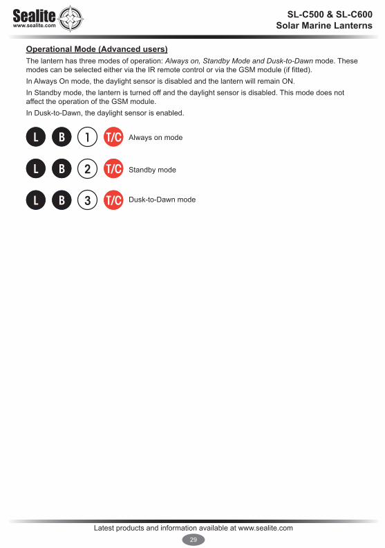
Operational Mode (Advanced users)The lantern has three modes of operation: Always on, Standby Mode and Dusk-to-Dawn mode. These modes can be selected either via the IR remote control or via the GSM module (if fitted).In Always On mode, the daylight sensor is disabled and the lantern will remain ON.In Standby mode, the lantern is turned off and the daylight sensor is disabled. This mode does not affect the operation of the GSM module.In Dusk-to-Dawn, the daylight sensor is enabled.
Always on mode
Standby mode
Dusk-to-Dawn mode
T/CT/CL B 1
T/CT/CL B 2
T/CT/CL B 3

Latest products and information available at www.sealite.com30
SL-C500 & SL-C600 Solar Marine Lanterns
Now that the lantern has been programmed to suit the project requirements, it’s important that the lantern is tested prior to installation, including flash code and intensity settings. To test the lantern:• Connect the SL-155 to a 12V power supply or battery • For lanterns programmed to “Dusk to Dawn” operation setting, cover lantern with a dark cloth or
jack in darkness for more than 1 minute. After this time the lantern will activate• Next, check that the lantern is flashing to the required flash code and intensity• If the settings are correct, disconnect from the 12V power supply or battery • If the settings are incorrect, following the Programming Instructions of this manual to re-configure
lantern characteristics, and then re-test prior to installation
IMPORTANT: when lantern is being programmed using the Sealite PC Configuration Tool software, it is recommended that the operation setting is set to “Always On” for ease of testing/viewing new settings. Once the programming is complete, remember to change the operation mode back to your specific installation requirement (Sealite recommend “Dusk to Dawn” mode).
Lantern Testing

Latest products and information available at www.sealite.com31
SL-C500 & SL-C600 Solar Marine Lanterns
Before activating the lantern, its flash characteristics and intensity must be set.Please follow the programming instructions in this manual to configure the lantern characteristics.
Unpack all hardware and verify container contents. Please contact your Sealite representative if there is any hardware missing.
Inspect all hardware for damage. If there is any damage, please contact your Sealite representative.
Before activating the lantern, its flash characteristics and intensity must be set.Please follow the programming instructions in this manual to configure the lantern characteristics.
IMPORTANT: a sealed vent in the base allows air transfer without moisture intake and should not be disturbed.
Lantern is activated by connecting +ve and -ve wires to +ve and -ve battery terminals.
1. From the front of the lantern, unscrew the four socket cap screws from the base of the solar unit, and remove the body from the base plate.
2. Unscrew the 4 retaining knobs and remove the battery box lid.3. To activate the lantern, connect the “Battery Negative (-)” wire to the negative terminal, and
the “Battery Positive (+)” wire to the positive terminal of the battery. Care must be taken when replacing internal battery lid to ensure internal wiring is clear from sealed gasket.
4. Replace the battery box lid, refit the 4 retaining knobs and tighten securely. 5. Replace the lantern body onto the base plate ensuring that no wiring is protruding, and screw four
socket cap screws up tight. 6. To test place dark cover (towel or jacket) on top of light to activate sensor, light will come on.7. Ensure that the unit is bolted to an even, flat surface.
Care must be taken to observe the polarity of each wire before they are connected.To ensure waterproofing of the unit, make sure that no wires are protruding and that
there is an even seal.
Installation
Latest products and information available at www.sealite.com32
SL-C500 & SL-C600 Solar Marine Lanterns
The lanterns can be fitted with a GPS module, and provide the user with the ability to install independently operating lanterns that all flash in synchronisation.No additional power supplies, aerials or control systems are required, and with its microprocessor-based system, the GPS option is specifically designed to provide maximum reliability and performance over a wide range of environmental conditions.
Operating PrincipleEach light operates independently and requires no operator intervention. A minimum of 4 satellites need to be in view for the built-in GPS receiver to collect time data. At dusk, the light sensor will turn the light on. If time data is available the light will come on synchronised to every other light with the same selected flash code. Synchronisation is achieved using an internal algorithm based on the highly accurate time base and time data received from the satellites. The satellite data is provided from a number of earth stations using atomic clocks as the time base. Continuous self-checking ensures that the light will continue to run in synchronisation.
Light ActivationAt power-up the microprocessor checks that the internal GPS module is programmed correctly and is able to provide valid time base and time data. Once outside with a clear view of the sky, valid data should become available within 20 minutes.
Daylight OperationDuring daylight hours the microprocessor is in idle mode to reduce power consumption. Time data continues to be updated once per second. The microprocessor will automatically exit the idle mode as soon as dark conditions are detected.
Dark OperationWhen dark conditions are detected the light:• Checks for valid time data and is turned on after a delay based on the current time and the length
of the selected flash code;• If valid time data is not detected the light will turn on after approximately 10 seconds. This light will
not be synchronised. • If the light turns on unsynchronised it will continually check for valid time data. Once valid data is
found the light will automatically synchronise. Note: Lights will not synchronise if different flash codes are selected.
Optional GPS Synchronisation

Latest products and information available at www.sealite.com33
SL-C500 & SL-C600 Solar Marine Lanterns
Optional GSM Monitoring & Control System
The lanterns may also be fitted with GSM Cell-Phone Monitoring and Control – enabling users to access real-time diagnostics data and change lantern settings via cell-phone. The system can also be configured to send out alarm SMS text messages to designated cellular telephone numbers. users can also have alarms and reports sent to designated email addresses.
Please contact Sealite for further information and instructions.

Latest products and information available at www.sealite.com34
SL-C500 & SL-C600 Solar Marine Lanterns
Designed to be virtually maintenance-free, the SL-C500 and SL-C600 require minimal attention, though the following maintenance and servicing information is provided to help ensure the life of your Sealite product. 1. Cleaning Lens- occasional cleaning of the light lens may be required. Using a cloth and warm
soapy water, wipe off any foreign matter before rinsing the lens with fresh water.2. Cleaning Solar Panels- occasional cleaning of the solar panels may be required. Using a cloth and
warm soapy water, wipe off any foreign matter before rinsing the panels with fresh water. 3. Battery Check- inspection of batteries should be performed every three years (minimum) to ensure
that the charger, battery and ancillary electronics are functioning correctly. Using a voltage meter, check that the battery voltage is at least 12 volts under 100MA load, and ensure all terminals are clear of foreign matter (SL125-C models only).
Replacing the BatteryThe SL-C500 & SL-C600 lanterns have a sealed battery compartment which provides the user with the ability to change the battery after years of operation. The 2-piece design ensures ease of maintenance, as the base remains fixed to the supporting structure.
1. From the front of the lantern, unscrew the four socket cap screws from the base of the lantern, and remove the body from the base plate.
2. Unscrew the 4 retaining knobs and remove the battery box lid.3. Disconnect the positive and negative wires from the battery. 4. Discard old battery in a safe manner. 5. Reattach positive and negative wires to the new battery. 6. Replace the battery box lid, refit the 4 retaining knobs and tighten securely. 7. Replace the lantern body onto the base plate ensuring that no wiring is protruding, and screw four
socket cap screws firmly. 8. To test place dark cover on top of light to activate sensor, light will come on.
Care must be taken to observe the polarity of each wire before they are connected. To ensure waterproofing of the unit, make sure that no wires are protruding and that there is an
even seal. Always discard old batteries in a safe manner.
Maintenance & Servicing

Latest products and information available at www.sealite.com35
SL-C500 & SL-C600 Solar Marine Lanterns
Problem RemedyUnable to communicate with lantern via USB
1. Connect the USB drive provided by Sealite to the PC and open to view files.
2. Double-click on the file: ???Configx.xx.exe (note, version number may vary)
3. Extract the executable file4. Connect the lantern to a power source5. Connect the lantern to the PC 6. Click “COM Setup” 7. Select the appropriate COM Port from the drop down menu in
the “Serial Port” dialogue box8. Ensure the “Open Port” check box is selected and “Port is Open”
is displayed9. Click “Ok”10.Lantern should be connected and ready for programming
Lantern will not activate. • Ensure lantern is in darkness• Wait at least 60 seconds for the program to initialise in darkness• Ensure battery terminals are properly connected• Ensure lantern is connected to a 12volt power supply
Flash Codes will not change. • Turn rotary switches several times to ensure contacts are clear.
Programming settings will not change
• Check programming cable is properly connected to both lantern and computer, and check that the lantern is connected correctly to a power source (and that the power source is charged eg. battery)
Trouble Shooting

Latest products and information available at www.sealite.com36
SL-C500 & SL-C600 Solar Marine Lanterns
Flash CodesSealite marine lanterns may be set to any of 256 IALA recommended flash settings which are user-adjustable onsite without the need for external devices.
SEALITE® code reference is listed by number of flashes
For the latest version of this document visit www.sealite.com or email [email protected]
SymbolsFL Flash followed by number Eg. FL 1 S, one flash every secondF FixedQ Quick flashVQ Very quick flashOC Occulting; greater period on than off ISO Isophase; equal period on and offLFL Long flash longMO Morse code ( ) contains letter
For example, VQ (6) + LFL 10 S means 6 very quick flashes followed by a long flash, during a 10-second interval.The amount of power your lantern draws through the night depends on the duty cycle, i.e. the amount of time on as a proportion to the timing cycle. For example, 0.5 seconds on and 4.5 seconds off equals a 10% duty cycle. It is best to operate at the lowest duty cycle appropriate to the actual needs of the application.
Recommended Rhythm for Flashing Light - IALA Regions A and B
MARK DESCRIPTION RHYTHMPort Hand & Starboard Marks: Any, other than Composite Group Flashing (2+1)
Preferred Channel Starboard: Composite Group Flashing (2+1)
Preferred Channel Port: Composite Group Flashing (2+1)
North Cardinal Mark: Very quick or quick
East Cardinal Mark: Very quick (3) every 5 seconds or quick (3) every 10 seconds
South Cardinal Mark: Very quick (6) + long flash every 10 seconds or quick (6) + long flash every 15 seconds
West Cardinal Mark: Very quick (9) every 10 seconds or quick (9) every 15 seconds
Isolated Danger Mark: Group flashing (2)
Safe Water Mark: Isophase, occulting, one long flash every 10 seconds or Morse Code “A”
Special Marks: Any, other than those described for Cardinal, Isolated Danger or Safe Water Marks
Appendix

Latest products and information available at www.sealite.com.au37
SWITCHIR
Controller FLASH CODE ON OFFA B0 0 0 F (Steady light)D 3 211 VQ 0.5 S 0.2 0.3E 3 227 VQ 0.6 S 0.2 0.4F 3 243 VQ 0.6 S 0.3 0.37 3 115 Q 1 S 0.2 0.88 3 131 Q 1 S 0.3 0.79 3 147 Q 1 S 0.4 0.6A 3 163 Q 1 S 0.5 0.58 4 132 Q 1 S 0.8 0.2B 3 179 Q 1.2 S 0.3 0.99 4 148 Q 1.2 S 0.5 0.7C 3 195 Q 1.2 S 0.6 0.6F 4 244 FL 1.5 S 0.2 1.31 0 16 FL 1.5 S 0.3 1.20 5 5 FL 1.5 S 0.4 1.10 4 4 FL 1.5 S 0.5 1.02 0 32 FL 2 S 0.2 1.83 0 48 FL 2 S 0.3 1.74 0 64 FL 2 S 0.4 1.65 0 80 FL 2 S 0.5 1.56 0 96 FL 2 S 0.7 1.37 0 112 FL 2 S 0.8 1.21 2 18 ISO 2 S 1.0 1.08 0 128 FL 2.5 S 0.3 2.29 0 144 FL 2.5 S 0.5 2.0D 6 214 FL 2.5 S 1.0 1.51 5 21 FL 3 S 0.2 2.8A 0 160 FL 3 S 0.3 2.72 5 37 FL 3 S 0.4 2.6B 0 176 FL 3 S 0.5 2.53 5 53 FL 3 S 0.6 2.4C 0 192 FL 3 S 0.7 2.3D 0 208 FL 3 S 1.0 2.02 2 34 ISO 3 S 1.5 1.55 4 84 OC 3 S 2.0 1.0E 2 226 OC 3 S 2.5 0.54 6 70 OC 3.5 S 2.5 1.04 5 69 FL 4 S 0.2 3.85 5 85 FL 4 S 0.3 3.7E 0 224 FL 4 S 0.4 3.6F 0 240 FL 4 S 0.5 3.56 5 101 FL 4 S 0.6 3.40 1 1 FL 4 S 0.8 3.21 1 17 FL 4 S 1.0 3.02 1 33 FL 4 S 1.5 2.53 2 50 ISO 4 S 2.0 2.03 6 54 OC 4 S 2.5 1.5F 2 242 OC 4 S 3.0 1.03 1 49 FL 4.3 S 1.3 3.08 5 133 FL 5 S 0.2 4.84 1 65 FL 5 S 0.3 4.75 1 81 FL 5 S 0.5 4.59 5 149 FL 5 S 0.9 4.16 1 97 FL 5 S 1.0 4.0
SWITCHIR
Controller FLASH CODE ON OFFA B7 1 113 FL 5 S 1.5 3.54 2 66 ISO 5 S 2.5 2.58 2 130 LFL 5 S 2.0 3.00 3 3 OC 5 S 3.0 2.01 3 19 OC 5 S 4.0 1.02 3 35 OC 5 S 4.5 0.5C 6 198 FL 6 S 0.2 5.8B 5 181 FL 6 S 0.3 5.7C 5 197 FL 6 S 0.4 5.68 1 129 FL 6 S 0.5 5.59 1 145 FL 6 S 0.6 5.4A 1 161 FL 6 S 1.0 5.07 5 117 FL 6 S 1.2 4.8B 1 177 FL 6 S 1.5 4.55 2 82 ISO 6 S 3.0 3.09 2 146 LFL 6 S 2.0 4.06 4 100 OC 6 S 4.0 2.03 3 51 OC 6 S 4.5 1.54 3 67 OC 6 S 5.0 1.0A 4 164 FL 7 S 1.0 6.09 6 150 FL 7 S 2.0 5.05 6 86 OC 7 S 4.5 2.5D 5 213 FL 7.5 S 0.5 7.0C 1 193 FL 7.5 S 0.8 6.7E 5 229 FL 8 S 0.5 7.5B 4 180 FL 8 S 1.0 7.06 2 98 ISO 8 S 4.0 4.0A 2 162 LFL 8 S 2.0 6.06 6 102 OC 8 S 5.0 3.0B 2 178 LFL 8 S 3.0 5.0F 5 245 FL 9 S 0.9 8.1C 4 196 FL 9 S 1.0 8.07 6 118 OC 9 S 6.0 3.00 6 6 FL 10 S 0.2 9.81 6 22 FL 10 S 0.3 9.7D 1 209 FL 10 S 0.5 9.52 6 38 FL 10 S 0.8 9.2E 1 225 FL 10 S 1.0 9.01 4 20 FL 10 S 1.5 8.5C 2 194 LFL 10 S 2.0 8.0D 2 210 LFL 10 S 3.0 7.07 2 114 ISO 10 S 5.0 5.02 4 36 LFL 10 S 4.0 6.08 6 134 OC 10 S 6.0 4.05 3 83 OC 10 S 7.0 3.06 3 99 OC 10 S 7.5 2.5F 1 241 FL 12 S 1.2 10.8D 4 212 FL 12 S 2.5 9.53 4 52 LFL 12 S 2.0 10.00 2 2 FL 15 S 1.0 14.04 4 68 LFL 15 S 4.0 11.07 4 116 OC 15 S 10 5.0A 6 166 LFL 20 S 2.0 18.0E 4 228 FL 26 S 1.0 25.0

Latest products and information available at www.sealite.com38
SL-C500 & SL-C600 Solar Marine Lanterns
SWITCHIR
Controller FLASH CODE ON OFF ON OFFA B0 A 10 FL (2) 4 S 0.5 1.0 0.5 2.0E B 235 VQ (2) 4 S 0.2 1.0 0.2 2.61 A 26 FL (2) 4.5 S 0.3 1.0 0.3 2.92 A 42 FL (2) 4.5 S 0.4 1.0 0.4 2.73 A 58 FL (2) 4.5 S 0.5 1.0 0.5 2.5F 9 249 FL (2) 5 S 0.2 0.8 0.2 3.82 C 44 FL (2) 5 S 0.2 1.2 0.2 3.44 A 74 FL (2) 5 S 0.4 0.6 0.4 3.60 7 7 FL (2) 5 S 0.5 1.0 0.5 3.01 7 23 FL (2) 5 S 1.0 1.0 1.0 2.09 B 155 Q (2) 5 S 0.3 0.7 0.3 3.72 9 41 Q (2) 5 S 0.5 0.5 0.5 3.55 A 90 FL (2) 5.5 S 0.4 1.4 0.4 3.37 8 120 FL (2) 6 S 0.3 0.6 1.0 4.1A A 170 FL (2) 6 S 0.3 0.9 0.3 4.56 A 106 FL (2) 6 S 0.3 1.0 0.3 4.47 A 122 FL (2) 6 S 0.4 1.0 0.4 4.29 9 153 FL (2) 6 S 0.5 1.0 0.5 4.02 8 40 FL (2) 6 S 0.8 1.2 0.8 3.23 7 55 FL (2) 6 S 1.0 1.0 1.0 3.03 9 57 Q (2) 6 S 0.3 0.7 0.3 4.7A 9 169 FL (2) 7 S 1.0 1.0 1.0 4.07 B 123 FL (2) 8 S 0.4 0.6 2.0 5.08 A 138 FL (2) 8 S 0.4 1.0 0.4 6.24 7 71 FL (2) 8 S 0.5 1.0 0.5 6.08 8 136 FL (2) 8 S 0.8 1.2 2.4 3.65 7 87 FL (2) 8 S 1.0 1.0 1.0 5.04 C 76 OC (2) 8 S 3.0 2.0 1.0 2.05 C 92 OC (2) 8 S 5.0 1.0 1.0 1.0F B 251 VQ (2) 8 S 0.2 1.0 0.2 6.69 A 154 FL (2) 10 S 0.4 1.6 0.4 7.66 7 103 FL (2) 10 S 0.5 1.0 0.5 8.07 7 119 FL (2) 10 S 0.5 1.5 0.5 7.56 9 105 FL (2) 10 S 0.5 2.0 0.5 7.08 7 135 FL (2) 10 S 0.8 1.2 0.8 7.2B 9 185 FL (2) 10 S 1.0 1.0 1.0 7.09 7 151 FL (2) 10 S 1.0 1.5 1.0 6.54 9 73 Q (2) 10 S 0.6 0.4 0.6 8.4B A 186 FL (2) 12 S 0.4 1.0 0.4 10.2C 9 201 FL (2) 12 S 0.5 1.0 0.5 10.0D 9 217 FL (2) 12 S 1.5 2.0 1.5 7.0A 8 168 FL (2) 15 S 0.5 1.5 2.0 11.0A 7 167 FL (2) 15 S 1.0 2.0 1.0 11.08 B 139 Q (2) 15 S 0.2 0.8 0.2 13.8C A 202 FL (2) 20 S 1.0 3.0 1.0 15.0D A 218 FL (2) 25 S 1.0 1.0 1.0 22.0
SWITCHIR
Controller FLASH CODE ON OFF ON OFF ON OFFA B7 9 121 Q (3) 5 S 0.5 0.5 0.5 0.5 0.5 2.55 9 89 VQ (3) 5 S 0.2 0.3 0.2 0.3 0.2 3.80 C 12 VQ (3) 5 S 0.3 0.2 0.3 0.2 0.3 3.7E 9 233 VQ (3) 5 S 0.3 0.3 0.3 0.3 0.3 3.53 C 60 FL (3) 6 S 0.5 1.0 0.5 1.0 0.5 2.52 B 43 FL (2+1) 6 S 0.3 0.4 0.3 1.2 0.3 3.5

Latest products and information available at www.sealite.com.au39
SWITCHIR
Controller FLASH CODE ON OFF ON OFF ON OFFA BA B 171 Q (3) 6 S 0.3 0.7 0.3 0.7 0.3 3.7F A 250 FL (3) 8 S 0.5 1.0 0.5 1.0 0.5 4.50 B 11 FL (3) 9 S 0.3 1.0 0.3 1.0 0.3 6.1B 7 183 FL (3) 9 S 0.8 1.2 0.8 1.2 0.8 4.2B 8 184 FL (3) 10 S 0.3 0.7 0.3 0.7 0.9 7.1C 8 200 FL (3) 10 S 0.4 0.6 0.4 0.6 1.2 6.8C B 203 FL (3) 10 S 0.5 0.5 0.5 0.5 0.5 7.5C 7 199 FL (3) 10 S 0.5 1.5 0.5 1.5 0.5 5.5D B 219 FL (3) 10 S 0.6 0.6 0.6 0.6 0.6 7.0D 7 215 FL (3) 10 S 1.0 1.0 1.0 1.0 1.0 5.03 8 56 FL (2+1) 10 S 0.5 0.7 0.5 2.1 0.5 5.78 9 137 OC (3) 10 S 5.0 1.0 1.0 1.0 1.0 1.0B B 187 Q (3) 10 S 0.3 0.7 0.3 0.7 0.3 7.7D 8 216 FL (2 + 1) 10 S 0.5 0.5 0.5 0.5 1.5 6.51 B 27 FL (3) 12 S 0.5 1.5 0.5 1.5 0.5 7.5E A 234 FL (3) 12 S 0.5 2.0 0.5 2.0 0.5 6.5E 7 231 FL (3) 12 S 0.8 1.2 0.8 1.2 0.8 7.2B 6 182 FL (3) 12 S 1.0 1.0 1.0 3.0 1.0 5.04 8 72 FL (2+1) 12 S 0.8 1.2 0.8 2.4 0.8 6.05 8 88 FL (2+1) 12 S 1.0 1.0 1.0 4.0 1.0 4.01 8 24 FL (2+1) 13.5 S 1.0 1.0 1.0 4.0 1.0 5.5F 7 247 FL (3) 15 S 0.3 1.7 0.3 1.7 0.3 10.79 D 157 FL (3) 15 S 0.4 1.0 0.4 1.0 0.4 11.80 8 8 FL (3) 15 S 0.5 1.5 0.5 1.5 0.5 10.5F 8 248 FL (2+1) 15 S 0.6 0.3 0.6 0.3 1.4 11.80 9 9 FL (2+1) 15 S 0.7 0.5 0.7 0.5 1.9 10.71 9 25 FL (2+1) 15 S 0.7 0.7 0.7 0.7 2.1 10.16 8 104 FL (2+1) 15 S 1.0 2.0 1.0 5.0 1.0 5.01 C 28 VQ (3) 15 S 0.1 0.5 0.1 0.5 0.1 13.74 B 75 FL (3) 20 S 0.5 3.0 0.5 3.0 0.5 12.53 B 59 FL (3) 20 S 0.5 1.5 0.5 1.5 0.5 15.55 B 91 FL (3) 20 S 0.8 1.2 0.8 1.2 0.8 15.26 B 107 FL (3) 20 S 1.0 1.0 1.0 1.0 1.0 15.0
SWITCHIR
Controller FLASH CODE ON OFF ON OFF ON OFF ON OFFA BB F 191 VQ (4) 4 S 0.3 0.3 0.3 0.3 0.3 0.3 0.3 2.3B D 189 Q (4) 6 S 0.3 0.7 0.3 0.7 0.3 0.7 0.3 2.78 D 141 Q (4) 6 S 0.4 0.6 0.4 0.6 0.4 0.6 0.4 2.61 D 29 FL (4) 10 S 0.5 1.0 0.5 1.0 0.5 1.0 0.5 5.02 D 45 FL (4) 10 S 0.8 1.2 0.8 1.2 0.8 1.2 0.8 3.2F E 254 Q (4) 10 S 0.3 0.7 0.3 0.7 0.3 0.7 0.3 6.7B E 190 FL (4) 12 S 0.3 1.7 0.3 1.7 0.3 1.7 0.3 5.74 F 79 FL (4) 12 S 0.5 0.5 0.5 0.5 0.5 0.5 0.5 8.5C E 206 FL (4) 12 S 0.5 1.5 0.5 1.5 0.5 1.5 0.5 5.53 D 61 FL (4) 12 S 0.8 1.2 0.8 1.2 0.8 1.2 0.8 5.2A D 173 Q (4) 12 S 0.3 0.7 0.3 0.7 0.3 0.7 0.3 8.74 D 77 FL (4) 15 S 0.5 1.5 0.5 1.5 0.5 1.5 0.5 8.58 E 142 FL (4) 15 S 1.0 1.0 1.0 1.0 1.0 1.0 1.0 8.07 D 125 FL (4) 15 S 1.5 0.5 0.5 0.5 0.5 0.5 0.5 10.5D E 222 FL (4) 16 S 0.5 1.5 0.5 1.5 0.5 1.5 0.5 9.5C D 205 FL (4) 20 S 0.3 3.0 0.3 3.0 0.3 3.0 0.3 9.85 D 93 FL (4) 20 S 0.5 1.5 0.5 1.5 0.5 1.5 0.5 13.50 D 13 FL (4) 20 S 0.5 1.5 0.5 1.5 0.5 4.5 0.5 10.53 F 63 FL (4) 20 S 1.5 1.5 1.5 1.5 1.5 1.5 1.5 9.50 F 15 Q (4) 20 S 0.5 0.5 0.5 0.5 0.5 0.5 0.5 16.5E E 238 Q (4) 28 S 0.5 0.5 0.5 0.5 0.5 0.5 0.5 24.56 F 111 FL (4) 30 S 0.5 0.5 0.5 0.5 0.5 0.5 0.5 26.5
Latest products and information available at www.sealite.com40
SL-C500 & SL-C600 Solar Marine Lanterns
SWITCHIR
Controller FLASH CODE ON OFF ON OFF ON OFF ON OFF ON OFF ON OFF ON OFF ON OFF ON OFFA B4 E 78 VQ (9) 10 S 0.2 0.3 0.2 0.3 0.2 0.3 0.2 0.3 0.2 0.3 0.2 0.3 0.2 0.3 0.2 0.3 0.2 5.85 E 94 VQ (9) 10 S 0.3 0.3 0.3 0.3 0.3 0.3 0.3 0.3 0.3 0.3 0.3 0.3 0.3 0.3 0.3 0.3 0.3 4.91 F 31 Q (9) 15 S 0.2 0.8 0.2 0.8 0.2 0.8 0.2 0.8 0.2 0.8 0.2 0.8 0.2 0.8 0.2 0.8 0.2 6.80 E 14 Q (9) 15 S 0.3 0.7 0.3 0.7 0.3 0.7 0.3 0.7 0.3 0.7 0.3 0.7 0.3 0.7 0.3 0.7 0.3 6.71 E 30 Q (9) 15 S 0.6 0.6 0.6 0.6 0.6 0.6 0.6 0.6 0.6 0.6 0.6 0.6 0.6 0.6 0.6 0.6 0.6 4.8
SWITCHIR
Controller FLASH CODE ON OFF ON OFF ON OFF ON OFFA BMORSE CODE ( ) INDICATES LETTER7 8 120 MO (A) 6 S 0.3 0.6 1.0 4.17 B 123 MO (A) 8 S 0.4 0.6 2.0 5.08 8 136 MO (A) 8 S 0.8 1.2 2.4 3.6B 8 184 MO (U) 10 S 0.3 0.7 0.3 0.7 0.9 7.1C 8 200 MO (U) 10 S 0.4 0.6 0.4 0.6 1.2 6.8D 8 216 MO (U) 10 S 0.5 0.5 0.5 0.5 1.5 6.59 8 152 MO (A) 10 S 0.5 0.5 1.5 7.58 9 137 MO (D) 10 S 5.0 1.0 1.0 1.0 1.0 1.0A 8 168 MO (A) 15 S 0.5 1.5 2.0 11.0F 8 248 MO (U) 15 S 0.6 0.3 0.6 0.3 1.4 11.80 9 9 MO (U) 15 S 0.7 0.5 0.7 0.5 1.9 10.71 9 25 MO (U) 15 S 0.7 0.7 0.7 0.7 2.1 10.17 D 125 MO (B) 15 S 1.5 0.5 0.5 0.5 0.5 0.5 0.5 10.5
SWITCHIR
Controller FLASH CODE ON OFF ON OFF ON OFF ON OFF ON OFFA BD D 221 Q (5) 7 S 0.3 0.7 0.3 0.7 0.3 0.7 0.3 0.7 0.3 2.7E D 237 Q (5) 10 S 0.3 0.7 0.3 0.7 0.3 0.7 0.3 0.7 0.3 5.7E 8 232 FL (5) 12 S 0.5 1.5 0.5 1.5 0.5 1.5 0.5 1.5 0.5 3.55 F 95 FL (5) 20 S 0.5 0.5 0.5 0.5 0.5 0.5 0.5 0.5 0.5 15.59 F 159 FL (5) 20 S 0.8 1.2 0.8 1.2 0.8 1.2 0.8 1.2 0.8 11.29 E 158 FL (5) 20 S 1.0 1.0 1.0 1.0 1.0 1.0 1.0 1.0 1.0 11.0
SWITCHIR
Controller FLASH CODE ON OFF ON OFF ON OFF ON OFF ON OFF ON OFFA BF D 253 Q (6) 10 S 0.3 0.7 0.3 0.7 0.3 0.7 0.3 0.7 0.3 0.7 0.3 4.7A F 175 FL (6) 15 S 0.3 0.7 0.3 0.7 0.3 0.7 0.3 0.7 0.3 0.7 0.3 9.77 F 127 FL (6) 15 S 0.5 1.0 0.5 1.0 0.5 1.0 0.5 1.0 0.5 1.0 0.5 7.0
SWITCHIR
Controller FLASH CODE ON OFF ON OFF ON OFF ON OFF ON OFF ON OFF ON OFFA B6 E 110 VQ (6) + LFL 10 S 0.2 0.3 0.2 0.3 0.2 0.3 0.2 0.3 0.2 0.3 0.2 0.3 2.0 5.07 E 126 VQ (6) + LFL 10 S 0.3 0.3 0.3 0.3 0.3 0.3 0.3 0.3 0.3 0.3 0.3 0.3 2.0 4.42 F 47 Q (6) + LFL 15 S 0.2 0.8 0.2 0.8 0.2 0.8 0.2 0.8 0.2 0.8 0.2 0.8 2.0 7.02 E 46 Q (6) + LFL 15 S 0.3 0.7 0.3 0.7 0.3 0.7 0.3 0.7 0.3 0.7 0.3 0.7 2.0 7.03 E 62 Q (6) + LFL 15 S 0.6 0.6 0.6 0.6 0.6 0.6 0.6 0.6 0.6 0.6 0.6 0.6 2.0 5.88 F 143 VQ (6) + LFL 15 S 0.3 0.3 0.3 0.3 0.3 0.3 0.3 0.3 0.3 0.3 0.3 0.3 2.0 9.4

Latest products and information available at www.sealite.com41
SL-C500 & SL-C600 Solar Marine Lanterns
SWITCHIR
Controller FLASH CODE ON OFF ON OFF ON OFF ON OFF ON OFF ON OFFA BF D 253 Q (6) 10 S 0.3 0.7 0.3 0.7 0.3 0.7 0.3 0.7 0.3 0.7 0.3 4.7A F 175 FL (6) 15 S 0.3 0.7 0.3 0.7 0.3 0.7 0.3 0.7 0.3 0.7 0.3 9.77 F 127 FL (6) 15 S 0.5 1.0 0.5 1.0 0.5 1.0 0.5 1.0 0.5 1.0 0.5 7.0
Notes

Latest products and information available at www.sealite.com42
SL-C500 & SL-C600 Solar Marine Lanterns
Activating the WarrantyUpon purchase, the Sealite Pty Ltd warranty must be activated for recognition of future claims. To do this you need to register on-line. Please complete the Online Registration Form at:www.sealite.comSealite Pty Ltd will repair or replace your LED light in the event of electronic failure for a period of up to three years from the date of purchase, as per the terms & conditions below.Sealite Pty Ltd will repair or replace any ancillary or accessory products in the event of failure for a period of up to one year from the date of purchase, as per the terms & conditions below.The unit(s) must be returned to Sealite freight prepaid.Warranty Terms 1. Sealite Pty Ltd warrants that any Sealite marine products fitted with telemetry equipment including but
not limited to AIS, GSM, GPS or RF (“Telemetry Products”) will be free from defective materials and workmanship under normal and intended use, subject to the conditions hereinafter set forth, for a period of twelve (12) months from the date of purchase by the original purchaser.
2. Sealite Pty Ltd warrants that any BargeSafe™ Series of LED barge light products (“BargeSafe™ Products”) will be free from defective materials and workmanship under normal and intended use, subject to the conditions hereinafter set forth, for a period of twelve (12) months from the date of purchase by the original purchaser.
3. Sealite Pty Ltd warrants that any LED area lighting products (“Area Lighting Products”) but not including sign lighting products will be free from defective materials and workmanship under normal and intended use, subject to the conditions hereinafter set forth, for a period of twelve (12) months from the date of purchase by the original purchaser.
4. Sealite Pty Ltd warrants that any ancillary products and accessories, not mentioned in other clauses in this section, will be free from defective materials and workmanship under normal and intended use, subject to the conditions hereinafter set forth, for a period of twelve (12) months from the date of purchase by the original purchaser.
5. Sealite Pty Ltd warrants that any LED sign lighting products (“Sign Lighting Products”) will be free from defective materials and workmanship under normal and intended use, subject to the conditions hereinafter set forth, for a period of three (3) years from the date of purchase by the original purchaser.
6. Sealite Pty Ltd warrants that any Sealite marine lighting products other than the Telemetry Products, BargeSafe™ Products, and Area Lighting Products (“Sealite Products”) will be free from defective materials and workmanship under normal and intended use, subject to the conditions hereinafter set forth, for a period of three (3) years from the date of purchase by the original purchaser.
7. Sealite Pty Ltd will repair or replace, at Sealite’s sole discretion, any Telemetry Products, BargeSafe™ Products, Area Lighting Products or Sealite Products found to be defective in material and workmanship in the relevant warranty period so long as the Warranty Conditions (set out below) are satisfied.
8. If any Telemetry Products, BargeSafe™ Products, Area Lighting Products or Sealite Products are fitted with a rechargeable battery, Sealite Pty Ltd warrants the battery will be free from defect for a period of one (1) year when used within original manufacturer’s specifications and instructions.
9. Buoy products are covered by a separate ‘Sealite Buoy Warranty’.
Warranty ConditionsThis Warranty is subject to the following conditions and limitations; 1. The warranty is applicable to lanterns manufactured from 1/1/2009.2. The warranty is void and inapplicable if:
a. the product has been used or handled other than in accordance with the instructions in the owner’s manual and any other information or instructions provided to the customer by Sealite;
b. the product has been deliberately abused, or misused, damaged by accident or neglect or in being transported; or
c. the defect is due to the product being repaired or tampered with by anyone other than Sealite or
Sealite LED Light Warranty V2.2

Latest products and information available at www.sealite.com43
SL-C500 & SL-C600 Solar Marine Lanterns
Information in this manual is subject to change without notice and does not represent a commitment on the part of the vendor. Sealite products are subject to certain Australian and worldwide patent applications.
authorised Sealite repair personnel. 3. The customer must give Sealite Pty Ltd notice of any defect with the product within 30 days of the
customer becoming aware of the defect. 4. Rechargeable batteries have a limited number of charge cycles and may eventually need to be replaced.
Typical battery replacement period is 3-4 years. Long term exposure to high temperatures will shorten the battery life. Batteries used or stored in a manner inconsistent with the manufacturer’s specifications and instructions shall not be covered by this warranty.
5. No modifications to the original specifications determined by Sealite shall be made without written approval of Sealite Pty Ltd.
6. Sealite lights can be fitted with 3rd party power supplies and accessories but are covered by the 3rd party warranty terms and conditions.
7. The product must be packed and returned to Sealite Pty Ltd by the customer at his or her sole expense. Sealite Pty Ltd will pay return freight of its choice. A returned product must be accompanied by a written description of the defect and a photocopy of the original purchase receipt. This receipt must clearly list model and serial number, the date of purchase, the name and address of the purchaser and authorised dealer and the price paid by the purchaser. On receipt of the product, Sealite Pty Ltd will assess the product and advise the customer as to whether the claimed defect is covered by this warranty.
8. Sealite Pty Ltd reserves the right to modify the design of any product without obligation to purchasers of previously manufactured products and to change the prices or specifications of any product without notice or obligation to any person.
9. Input voltage shall not exceed those recommended for the product.10. Warranty does not cover damage caused by the incorrect replacement of battery in solar lantern models.11. This warranty does not cover any damage or defect caused to any product as a result of water flooding or
any other acts of nature.12. There are no representations or warranties of any kind by Sealite or any other person who is an agent,
employee, or other representative or affiliate of Sealite, express or implied, with respect to condition of performance of any product, their merchantability, or fitness for a particular purpose, or with respect to any other matter relating to any products.
Limitation of LiabilityTo the extent permitted by acts and regulations applicable in the country of manufacture, the liability of Sealite Pty Ltd under this Warranty will be, at the option of Sealite Pty Ltd, limited to either the replacement or repair of any defective product covered by this Warranty. Sealite will not be liable to Buyer for consequential damages resulting from any defect or deficiencies.
Limited to Original Purchaser This Warranty is for the sole benefit of the original purchaser of the covered product and shall not extend to any subsequent purchaser of the product.
MiscellaneousApart from the specific warranties provided under this warranty, all other express or implied warranties relating to the above product is hereby excluded to the fullest extent allowable under law. The warranty does not extend to any lost profits, loss of good will or any indirect, incidental or consequential costs or damages or losses incurred by the purchaser as a result of any defect with the covered product.
WarrantorSealite Pty Ltd has authorised distribution in many countries of the world. In each country, the authorised importing distributor has accepted the responsibility for warranty of products sold by distributor. Warranty service should normally be obtained from the importing distributor from whom you purchased your product. In the event of service required beyond the capability of the importer, Sealite Pty Ltd will fulfil the conditions of the warranty. Such product must be returned at the owner’s expense to the Sealite Pty Ltd factory, together with a photocopy of the bill of sale for that product, a detailed description of the problem, and any information necessary for return shipment.

Latest products and information available at www.sealite.com44
SL-C500 & SL-C600 Solar Marine Lanterns
Marine Lanterns (1–19NM)
Bridge & Barge Lights
Area Lighting
Monitoring & Control Systems
Marine Buoys(up to 3mt in diameter)
Mooring Systems & Accessories
Other Sealite Products Available
Head OfficeSealite Pty Ltd11 Industrial Drive Somerville, Vic 3912 AustraliaTel: +61 3 5977 6128 Fax: +61 3 5977 6124Email: [email protected]: www.sealite.com