solar occultation measurements 6 april 2004 remote sensing ...toohey/randall.pdf1 solar occultation...
TRANSCRIPT

1
Solar Occultation Measurements
6 April 2004Remote Sensing of Atmospheres and Oceans, ATOC 5235
Cora Randall: [email protected]
Topics:Review of related material in StephensMeasurement techniqueBasic retrieval

2
Review of previous related material in Stephens
Section 3.6.2 (Grating Spectrometers): SAGE I optical system description & schematic
Sections 3.4 and 6.1: Lambert & Beer’s LawsLambert: Transmission is proportional to the incident light intensity and path length.
(C is a proportionality constant)
Beer: The Lambert proportionality constant is defined by the extinction coefficient (kext,λ) of the interfering medium.
( ) dsIsCdI λλ −=
where ksca,λ is the scattering coefficient and kabs,λ is the absorption coefficient.
( )∫=−==
dsskIIT
ext
oτ
τ )exp(/
τ = optical thickness. Integrate over the pathlength.
Lambert-Beer
dIλ = -kext,λ(s) Iλdskext,λ = ksca,λ + kabs,λ
Note: Stephens uses “σ” instead of “k”, which I use to avoid confusion since “σ” often refers to the molecular cross-section (k = σ n, n =number density).

3
( ) )exp(/ ioi IhIT λλ τ−==
( )∫∞
=0
, dsskexti
λλτ
Tλ Transmittance (unitless)λ Wavelength hi Tangent altitude for the ith line of sight (km)I(hi) Intensity at altitude hi (J s-1 m-2 ster-1)Io Intensity at “top” of atmosphere (J s-1 m-2 ster-1)τiλ Optical thickness along the line of sight for tangent altitude hi (unitless)kext,λ Volume extinction coefficient (cm-1)
Section 6.2.2: Limb Profiling by Extinction – SAGE
Note: The terms optical “thickness” and optical “depth” are often used interchangeably. Conventionally in planetary science, however, optical depth refers to the optical thickness along the vertical optical path.
kext = kRay + kO3 + kNO2 + kH2O+ kaer + ….k = σ nσ = absorption or scattering cross-section (cm2)
(depends on wavelength, temperature and pressure)n = number density (cm-3)
We wish to solve for n

4
Locations of POAM spectral filters
Transmissions depend on wavelength according to the amount of absorption or scattering that various atmospheric constituents exhibit at that wavelength.
In the spectral range from 350-1200 nm the significant absorbers include O3, NO2, O2, and H2O, and scattering includes aerosol and Rayleigh (i.e., N2+O2).
Example: POAM O3channel is at 600 nm. 600-nm light is also attenuated by NO2absorption and Rayleigh & aerosol scattering, so these contributions are measured using other wavelengths.
For “differential” measurements (e.g., H2O), Rayleigh and aerosol scattering nearly cancel out.
Chappuis band
NO2 O3 O2 H2O

5
Solar occultation instruments view the sun as it is occulted by the atmosphere, measuring the attenuation of sunlight as this occurs.
Measurements are made as the satellite enters into the dayside (sunrise) or into the nightside (sunset).
Thus, they only occur at the intersection of the satellite orbit and the terminator (boundary separating day from night).
Characteristics of Solar Occultation Measurements
Occultation: The disappearance of a star, planet, or other celestial body as it moves out of sight behind another celestial body.

6
That measurements occur only at the orbit/terminator intersection implies:
Two occultations occur in each orbit, one in the northern hemisphere, and one in the southern hemisphere.
Total number of occultations each day depends on length of satellite orbit (altitude of satellite).Typically 14 in each hemisphere for low earth orbit (LEO, ~600-900 km).
Longitude separation of successive measurements depends on amount the earth has rotated during the satellite orbit. Longitude separation is typically 25 degrees for LEO.
Latitude of the measurements depends on relative positions of the terminator and satellite orbit, but is nearly constant on any given day, in each hemisphere. Latitude varies according to orbit inclination and season.
SunEarth
SunsetOccultation
SunriseOccultation

7
Example of measurement latitudes during 1995 for SAGE II & POAM II.
POAM sunrise (sr) in NH, sunset (ss) in SH. SAGE sr & ss occur in both hemispheres.
Altitudes: Mid-troposphere through the thermosphere. Lowest altitude limited by sunlight attenuation due to clouds and aerosols.
Example of measurement locations from 1 Dec 2002.
POAM high lat, HALOE low lat, SAGE3 high lat in NH & mid lat in SH.
Points usually spaced equally in longitude: gaps mean missed measurements.

8
March 21 June 21 September 21 December 21
Visualization of the orbit/terminator crossings for a near-polar, sun-synchronous orbit. The orbit is denoted by the dark black line. The terminator is the boundary between the white and gray shaded regions. The solar occultation measurement location is where the orbit crosses the terminator. Light gray lines should be ignored.
North
South

9
Solar occultation instruments since 1979
Infrared (λ > 2 µm) instrumentsdetect many more constituents because of rich vibrationalspectra.

10
There are two different standard ways of tracking the sun during an occultation event. (1) Stare at the center of brightness of the sun and track it steadily as the sun apparently rises or sets. This is an example of the POAM method:
The “raw” signal is counts vs. time. Time must be converted to tangent altitude based on the ephemeris of the spacecraft and pointing of the instrument, and counts are converted to transmission. The plot below shows an example for POAM. Each line represents a different wavelength channel.
Above atmosphere
In a
tmos
pher
e
Sun scan for normalization (Io)POAM field of view
(0.8 arcmin high by 50 arcmin wide) and possible position on the sun.
Sunrise Event
30 arcmin (0.5°)

11
Signal (counts) oscillates up and down as instrument scans across the dim lower edge (“limb”) of the sun, to the bright center, and then across the dim top edge (or the reverse). Lines indicate position of top and bottom of the Sun, and scan motion of SAGE III scan mirror across the solar disk.
(2) Repeatedly scan up and down the sun as it apparently rises or sets. This is an example of the SAGE method.
█
SAGE field of view (0.5x1.5 arcmin) and possible position on the sun.
Sunrise EventSun scan for normalization (Io)
In atmosphere

12
Earth
To Sun
Solar occultation viewing geometry(e.g., Figure 6.7 in Stephens)
The instrument measures the slant path transmission at successive tangent heights, zT, in each wavelength channel.
zTSlant Path
13
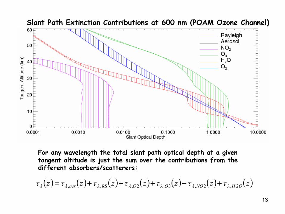
Slant Path Extinction Contributions at 600 nm (POAM Ozone Channel)
( ) ( ) ( ) ( ) ( ) ( ) ( )zzzzzzz OHNOOORSaer 2,2,3,2,,, λλλλλλλ τττττττ +++++=
For any wavelength the total slant path optical depth at a giventangent altitude is just the sum over the contributions from thedifferent absorbers/scatterers:

14
Simplified Solar Occultation Retrieval
1. Spectral Inversion of slant optical depthGoal: To separate contributions from different absorbers & scatterers
For most visible wavelengths:
τ = τaer + σO3NO3 + σNO2NNO2 + σH2ONH2O + σRSNtot + σO2NO2
(σ & τ are understood to be wavelength-dependent)
Solve for τaer and Ngas at each tangent altitude.N here is the slant column density.
τaer(λ) depends on particle size distribution, refractive index, particle shape, etc.Simplify by parameterizing:
ln τaer = µo + µ1κ(λ) + µ2 κ2(λ) , κ(λ) = ln λ
System of Equations7 unknowns (µo, µ1, µ2, NO3, NNO2, NH2O, NO2)
9 equations (# wavelengths)

15
Simplified Solar Occultation Retrieval (cont)
2. Limb InversionConvert slant path column densities, N, (or aerosol optical depth) to vertical profiles
of number density, n (or extinction):∫= sunsat OO dssniN )()( 33
Simplification:Discrete sum over 1-km shells to
generate a system of equations:
ijij
q
hOO ssnhN ∆= ∑
−)(2)(
1
33∆sij
zij
zt=zh
i j j+1 q-1
n(sij) = number density in shell ij.
q = highest altitude.∆sij = path length
thru shell ij.2X factor from spherical symmetry.
h

16
Advantages and Disadvantages of Solar Occultation Measurements
Advantages Disadvantages• High precision • Limited latitude coverage• High accuracy • Daytime only• High vertical resolution • Clouds limit tropospheric data• Self-calibrating
Some error sources in solar occultation measurements
• Assumption of spherical homogeneity – poor assumption in the presence of clouds, and generally in the troposphere.• Solar refraction at low altitudes – determining proper Io reference location.• Cross-section uncertainties (esp. temperature dependence).• Cross-section parameterization instead of line-by-line.• Aerosol spectra – and thus separation of aerosol and gas extinction – esp. in the presence of clouds.• Sunspots – esp. for fov that spans the width of the sun.• Spacecraft ephemeris errors – Where is the satellite? Can cause overall altitude shift.• Instrument Pointing Uncertainties – Where on the sun is the instrument pointed? Can cause “normalization” errors (incorrect Io is used).• Statistical noise.• Dark count errors.

17
7:21 pm 7:24 pm
7:26 pm 7:27 pm
http://www.isc.tamu.edu/~astro/research/sandiego.htmlCourtesy of Andrew Young, Texas A&M University
Examples of solar refraction at sunset
Example of sunspot effects
Figure shows projection of the POAM science channel field of view (fov) on the solar disk.
Sunspots cause errors when registration of the fov on the sun is not known perfectly.

18
Solar Occultation Instrument Acronyms
ACE Atmospheric Chemistry ExperimentATMOS Atmospheric Trace Molecule Spectroscopy ExperimentHALOE HALogen Occultation ExperimentILAS Improved Limb Atmospheric SpectrometerPOAM Polar Ozone and Aerosol MeasurementSAGE Stratospheric Aerosol and Gas ExperimentSAM Stratospheric Aerosol MeasurementSCIAMACHY SCanning Imaging Absorption SpectroMeter for Atmospheric
CHartographY
Useful References (and references therein)
SAGE II Inversion Algorithm, Chu et al., JGR 94, 8339-8352, 1989.
SAGE III Algorithm Theoretical Basis Document (ATBD): Transmission Level 1B Data Products, LaRC special report, 2002; http://www-sage3.larc.nasa.gov/library/
POAM III Retrieval Algorithm and Error Analysis, Lumpe et al., JGR 107 (D21), 4575, doi:10.1029/2002JD002137, 2002.
The Halogen Occultation Experiment, Russell et al., JGR 98, 10,777-10,798, 1993.
http://scienceworld.wolfram.com/physics