solar owner's charge manual controller - samlex america · solar charge controller msk-10a...
TRANSCRIPT
Solar Charge Controller
MSK-10A
Please read this manual before using your Solar Charge Controller.
owner's Manual

2 | SAMLEX AMERICA INC.
Owner'S Manual | Index
Section 1Safety Instructions ................................................................. 3
Section 2General Information, Features & Layout ............................... 5
Section 3Installation ........................................................................... 7
Section 4Operation ........................................................................ 13
Section 5Protections, Troubleshooting & Maintenance ..................... 22
Section 6Specifications ...................................................................... 25
Section 7Warranty ........................................................................ 27

2 | SAMLEX AMERICA INC. SAMLEX AMERICA INC. | 3
SeCtIOn 1 | Safety Instructions
IMPORTANT SAFETY INSTRUCTIONS
PLeASe ReAD tHe FoLLoWinG SAFetY inStRUctionS BeFoRe USinG tHe cHARGe contRoLLeR. FAiLURe to ABiDe BY tHe RecoMMenDAtionS MAY cAUSe PeRSonAL inJURY / DAMAGe to tHe contRoLLeR.
The following safety symbols will be used in this manual to highlight safety and information:
WARninG!Indicates possibility of physical harm to the user in case of non-compliance.
! cAUtion!
Indicates possibility of damage to the equipment in case of non-compliance.
i
inFoIndicates useful supplemental information.
WARninGS !
cAUtionS!
1. This Charge Controller is not waterproof (Ingress Protection rating is IP-30). PLeASe eNSUre THAT THe UNIT IS INSTALLeD IN DrY, CooL AND WeLL VeNTILATeD eNVI-roNMeNT.
2. The design of the Charge Controller allows oNLY Positive grounding, where re-quired. Ground the Positive terminal of the PV Panel(s) input on the Charge Controller or the Positive terminal of the battery. Do NoT ground the Negative.
3. There are no user serviceable parts inside the controller. Do not disassemble or attempt to repair it.
4. Install external fuses / breakers as required.5. Disconnect the PV Panel(s) and fuse / breakers near to battery before installing or
adjusting the controller. 6. Confirm that power connections are tightened to avoid excessive heating from
loose connection.7. To reduce the risk of injury, charge only 12V / 24V Lead Acid batteries - flooded,
AGM or Gel Cell types. other types of batteries may be subject to bursting which can lead to personal injury & damage.
8. Comply with battery manufacturer’s recommendations. 9. Avoid charging damaged, defective or old battery. 10. ensure correct polarity is maintained when connecting the Charge Controller to the
battery - Connect the Positive output terminal to the Positive battery Post and the Negative output terminal to the Negative battery Post. reversal of polarity connec-tion will blow the external inline protective fuse.

4 | SAMLEX AMERICA INC.
SeCtIOn 1 | Safety Instructions
11. When charging, removal of the battery from the vehicle is not necessary provided the battery is being charged in a well-ventilated area.
12. batteries contain very corrosive diluted Sulphuric Acid as electrolyte. Precautions should be taken to prevent contact with skin, eyes or clothing. If the battery acid makes contact with skin or clothing, flush immediately with water. See a doctor immediately.
13. batteries generate Hydrogen and oxygen during charging resulting in evolution of explosive gas mixture. Care should be taken to ventilate the battery area and fol-low battery manufacturer’s recommendations.
14. ensure there are no flammable substances, explosive gases, flames, smoke or spark near the battery or the PV Panel(s).
15. Use caution to reduce the risk of dropping a metal tool on the battery. It could spark or short circuit the battery or other electrical parts and could cause an explosion.
16. remove metal items like rings, bracelets and watches when working with batteries. batteries can produce a short circuit current high enough to weld a ring or the like to metal and thus cause a severe burn.
17. If you need to remove a battery, always remove the ground terminal from the bat-tery first. Make sure that all the accessories are off so that you do not cause a spark.
18. PV Panel(s) generate electrical power when exposed to sunlight. Place a dark cover over the panels when handling panels that have bare, un-insulated output wires. Accidental shorting of panel terminals or wiring connected to the panels can result in spark causing personal injury or a fire hazard.
19. It is important that the battery gets fully charged frequently (at least once per week). otherwise, the battery can become permanently damaged due to under charging. Partially charged batteries can quickly sulfate internally which is an ir-reversible condition. It is good practice to prevent a battery from being discharged below 50%. Deeper discharging severely shortens battery life.
20. Keep the surface of PV Panel(s) clean from dust. Clean with a soft cloth. Do not walk on the panels.
21. Installation and wiring must comply with the local and National electrical Codes and must be done by a certified electrician.

4 | SAMLEX AMERICA INC. SAMLEX AMERICA INC. | 5
SeCtIOn 2 | General Information, Features & layout
MSK-10A is a 10A rated, Series Type of PWM (Pulse Width Modulation) Charge Control-ler. It is based on an advanced design using a microcontroller for digital accuracy and fully automatic operation. It can be used for 12V or 24V systems for solar charging. PWM battery charging has been optimized for longer battery life. The unit is designed for user-friendly operation. Please take the time to read this owner’s Manual and follow the instructions step by step to help you make full use of the charging system.
FeAtUReS- Advanced microcontroller based, high performance design for digital accuracy and fully
automatic and intelligent operation - Series Type PWM (Pulse Width Modulation) charging for low loss, higher efficiency
charging and longer battery life - Up to 50V open Circuit Voltage (Voc) and up to 10A Short Circuit Current (Isc) of PV
Panel(s) - enables use of up to 150W of 12V Nominal panels for 12V battery and up to 300W, 24V Nominal panels for 24V Nominal battery.
- Dual voltage capability – can be used with 12V / 24V Nominal PV Panel(s) / batteries. 12V / 24V Nominal battery System is detected automatically: battery voltage < 18V is detected as 12V Nominal battery and >18V is detected as 24V Nominal battery
- 4 Stages of charging for 100% return of capacity and long battery life – bulk, Absorption, float and equalization Stages
- Choice to select charging parameters for 3 battery types - flooded, Sealed AGM or Sealed Gel Cell for complete and safe charging.
- User friendly LeD display for monitoring of operation and self diagnostics for troubleshooting
- Integrated Temperature Sensor for temperature compensation to ensure improved charging of batteries that experience wider temperature variations during the year
- MoSfeT based reverse current blocking for night-time battery discharge prevention. This allows much lower losses as compared to Diode based blocking
- electronic protections: over charging, over discharging, over heating and overload and short circuit on the Load Terminals.
- reverse polarity protection: any combination of PV Panel(s) and battery
APPLicAtionS - recreational / Service Vehicles - off grid- Portable Charging Kits- boats and marine crafts - field work / mobile offices - Telecommunications

6 | SAMLEX AMERICA INC.
LAYoUt
Fig 2.1: LeGenD
1. teMPeRAtURe SenSoR: Senses ambient temperature for temperature compensation for charging and discharging.
2. StAtUS LeD “PV” :
3. StAtUS LeD “BAtt”
4. StAtUS LeD “FLooDeD”: flooded type of battery has been selected
5. StAtUS LeD “GeL”: Sealed, Gel Cell type of battery has been selected.
6. StAtUS LeD “SeALeD”: Sealed, AGM type of battery has been selected.
7. StAtUS LeD “LoAD” : Displays the status of the load
8. SettinG BUtton:
- Switch oN and Switch off the load connected to the Load Terminals.
- Select battery type
9. Terminals for connecting PV Panel(s)
10. Terminals for connecting battery
11. Terminals for connecting load(s) - Maximum 10A
SeCtIOn 2 | General Information, Features & layout
1 2 3 4 5 6
7
8
9 10 11
fig 2.1: MSK-10A Layout

6 | SAMLEX AMERICA INC. SAMLEX AMERICA INC. | 7
SeCtIOn 3 | Installation
WARninG! !
cAUtion!
PLeASe ReAD ALL tHe SAFetY inStRUctionS GiVen in Section 1 BeFoRe inStALLinG AnD oPeRtinG tHe contRoLLeR. FAiLURe to ABiDe BY tHe RecoMMenDAtionS MAY cAUSe PeRSonAL inJURY / DAMAGe to tHe kit.
Do not USe tHe Unit in Wet enViRonMent• Pleasenotethatthisunitisnotwaterproof(itsIngressProtectionRatingis
iP-30).Hence,pleaseensurethattheunitisinstalledindryenvironment.
GRoUnDinG• ThedesignofthiscontrollerallowsonlyPositiveGrounding.Groundthe
PositiveTerminaloftheSolarArrayinputontheChargeControllerorthe PositiveTerminalofthebattery.DonotgroundtheNegative.
BAtteRY tYPeS• ChargeonlyleADACIDbATTeRIeS-flooDeD,SeAleD(AGm)oRSeAleD
(GelCell)types
WiRe SizinG• Selectthesystemcablesaccordingto3A/mm2currentdensity.
MoUntinGWhen mounting the controller, ensure free air through the controller heat sink fins. There should be at least 6 inches (150 mm) of clearance above and below the controller to allow for cooling. If mounted in an enclosure, ventilation is highly recommended.
WARninG!
RiSk oF exPLoSion! neVeR inStALL tHe contRoLLeR in A SeALeD encLo-SURe WitH FLooDeD BAtteRieS! Do not inStALL in A conFineD AReA WHeRe BAtteRY GASSeS cAn AccUMULAte.
Step1:ChoosemountinglocationLocate the controller on a vertical surface protected from direct sun, high temperature, and water. And make sure there is good ventilation.
Step2:CheckforClearancePlace the controller in the location where it will be mounted. Verify that there is suffi-cient room to run wires and that there is sufficient room above and below the controller for airflow.

8 | SAMLEX AMERICA INC.
SeCtIOn 3 | Installation
figure 3-1 Mounting & Cooling
Step3:markHolesUse a pencil or pen to mark the four (4) mounting hole locations on the mounting surface.
Step4:DrillHolesremove the controller and drill 4.5Mm holes in the marked locations.
Step5:SecureControllerPlace the controller on the surface and align the mounting holes with the drilled holes in step 4. Secure the controller in place using the mounting screws.
WiRinG
i
inFo
• Arecommendedconnectionsequencehasbeenprovidedbelowfor maximum safety during installation.
• ThecontrollerisacommonPositivegroundcontroller. !
cAUtion!
• DoNoTCoNNeCTloADSToTHeloADTeRmINAlSwITHSuRGePoweR exceeDinG 10A.
• foRmobIleAPPlICATIoNS,beSuReToSeCuReAllwIRING.
Warm Air
Cool Air
150 mm / 5.9"
150 mm / 5.9"
8 | SAMLEX AMERICA INC. SAMLEX AMERICA INC. | 9
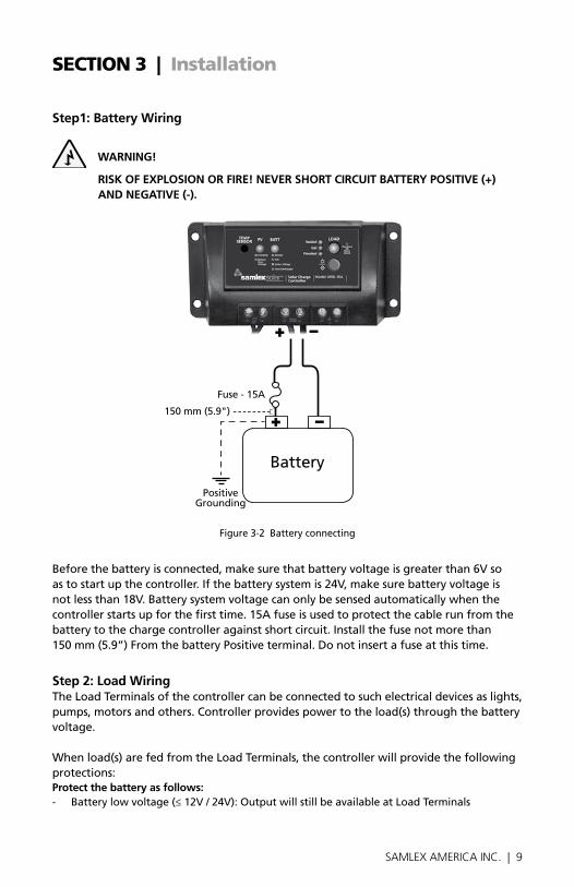
Step1:batterywiring
WARninG!
RISkofexPloSIoNoRfIRe!NeveRSHoRTCIRCuITbATTeRyPoSITIve(+)ANDNeGATIve(-).
figure 3-2 battery connecting
before the battery is connected, make sure that battery voltage is greater than 6V so as to start up the controller. If the battery system is 24V, make sure battery voltage is not less than 18V. battery system voltage can only be sensed automatically when the controller starts up for the first time. 15A fuse is used to protect the cable run from the battery to the charge controller against short circuit. Install the fuse not more than 150 mm (5.9”) from the battery Positive terminal. Do not insert a fuse at this time.
Step2:loadwiringThe Load Terminals of the controller can be connected to such electrical devices as lights, pumps, motors and others. Controller provides power to the load(s) through the battery voltage.
When load(s) are fed from the Load Terminals, the controller will provide the following protections:Protectthebatteryasfollows:- battery low voltage (≤ 12V / 24V): output will still be available at Load Terminals
SeCtIOn 3 | Installation
battery
fuse - 15A
150 mm (5.9")
Positive Grounding

10 | SAMLEX AMERICA INC.
SeCtIOn 3 | Installation
- battery over discharged (≤ 11.1V / 22.2V): output to Load Terminals will be disconnected
Protecttheloadasfollows:- overload or short circuit in the load connected to the Load Terminals: output
to Load Terminals will be disconnected
figure 3-3 Load wiring
Connect the Positive (+) and Negative (-) of load(s) to controller Load Terminals as shown in figure 3-3.
An in-line fuse should be wired in series in the load Positive (+) or Negative (-) wire as show in figure 3-3. Do not insert a fuse at this time.
If the Load Terminals of the controller are fed to a distribution panel for further distribution to the loads, each load circuit should be fused separately. ensure that the maximum total running / start up current draw of the load(s) is less than 10A.
Step3:Solarwiring
WARninG!
RiSk oF eLectRic SHock! exeRciSe cAUtion WHen HAnDLinG SoLAR wIRING.THePvPANel(S)HIGHvolTAGeouTPuTCANCAuSeSeveReSHoCkoRINjuRy.CoveRTHePvPANel(S)(S)fRomTHeSuNbefoReINSTAllINGSoLAR WiRinG.
fuse - 10A Load(s)

10 | SAMLEX AMERICA INC. SAMLEX AMERICA INC. | 11
The controller can accept 12V (36 cell) or 24V nominal (72 cell) PV panel(s) with maxi-mum open Circuit Voltage Voc of up to 50V.
figure 3-4 Solar wiring
Step4:ConfirmwiringDouble-check the wiring in step1 through 3 as shown in fig 3.5. Confirm correct polarity at each connection. Verify that all six terminals on the controller are tightened firmly.
SeCtIOn 3 | Installation
Solar Panel
Positive Grounding

12 | SAMLEX AMERICA INC.
SeCtIOn 3 | Installation
figure 3.5 System wiring review
Step5:InstallfuseInstall 10A fuse in each fuse holder in the following order:
1. battery circuit2. Load circuit
Step6:ConfirmPoweronWhen battery power is applied and the controller starts up, the battery Status LeD “bATT” (3, fig 2.1) will be GreeN.
If the controller doesn't start up, or the battery Status LeD error exists, please refer to Section 5 for Troubleshooting.
battery 1
2
3
fuse - 10A
fuse - 10A

12 | SAMLEX AMERICA INC. SAMLEX AMERICA INC. | 13
SeCtIOn 4 | Operation
PRinciPLe oF oPeRAtion oF SoLAR cHARGinG WitH SeRieS tYPe PulSewIDTHmoDulATIoN(Pwm)CoNTRolThe design and operation of MSK-10A is based on Series Type PWM (Pulse Width Modulation) control at PWM frequency of 25 Hz.
PWM exPLAnAtionThe output of the PV Panel(s) is connected to the battery in series with a Mosfet Switch inside the controller. A Micro-controller controls the oN / off operation of the Mosfet Switch to control the charging current and consequently, the State of Charge of the battery. A PV Panel is a current source that outputs constant current equal to its Short Circuit Current (Isc) over a wide voltage range (provided Irradiance Level, Spectrum and Cell Temperature remain constant). for example, at STC, a typical 12V nominal, 45W PV Panel may provide constant Short Circuit Current (Isc) of around 3A over voltage range from 0V to around 15V. PWM consists of repetitive cycles of controlled duration of oN and off states of the Series Connected Mosfet Switch inside the controller. The sum of oN and off times of one cycle is called the Pulse Period. In PWM control, the duration of the Pulse Width (oN time) is varied (modulated) and is defined by “Duty Cycle” which is the ratio of the “oN Time” to the “Pulse Period ”. Duty Cycle is normally specified in %. Thus, 0% Duty Cycle will mean that the switch is constantly off (will output 0A) and 100% Duty Cycle will mean that the switch is constantly oN and will output the full instantaneous Short Circuit Current “Isc” of the panel. for Duty Cycles > 0% and < 100%, the switch will alternate between oN and off states in a controlled manner in every cycle and will output variable current within a range of 0A to the full Short Circuit Current Isc. Thus, through PWM control, the Mosfet Switch inside the controller converts constant Short Circuit Current (Isc) of the PV Panel(s) to controlled average charging current at its output by varying the Duty Cycle. The average value of the charging current is equal to the instantaneous input value of Short Circuit Current (Isc) of the panel multiplied by the Duty Cycle.
PWM cHARGinG in MSk-10A battery charging is a current based process. Current fed to the battery results in re-charging of the cells and consequent rise in battery voltage. Controlling the current will control battery voltage. for 100% return of capacity, and for prevention of excessive gassing and sulfation, the battery charging voltage is required to be controlled at the specified Voltage regulation Set Points for Absorption (boost), float and equalization Charging Stages for different battery types. battery can, thus, be charged at the speci-fied Voltage regulation Set Points by PWM of the charging current through control of Duty Cycle as explained above. The controller checks the battery voltage and updates the Duty Cycle regularly at a very fast rate. The Duty Cycle is proportional to the differ-ence between the sensed battery voltage and the Voltage regulation Set Point. once the specified Voltage regulation Set Point is reached, it is kept steady - rise in voltage is compensated by reducing the average current by reducing the Duty Cycle and fall in

14 | SAMLEX AMERICA INC.
SeCtIOn 4 | Operation
voltage is compensated by raising the average current by raising the Duty Cycle. These fast updates on battery voltage measurements and Duty Cycle corrections ensure charg-ing of the battery at the specified Voltage regulation Set Point with minimum voltage deviation.
optimumPwmfrequency: The PWM frequency can range from tens of Hz to around 1000 Hz. At higher frequencies, the time period between the cycles is lesser and is not sufficient to complete the electro-chemical reactions. At lower frequencies, the rise times of the charging pulses are lower which results in higher gas bubble formation resulting in lowering of active surface area and increase of internal impedance. In MSK-10A, frequency of 25 Hz is used for optimum charging performance.
benefitsofpulsingnatureofchargingcurrentduringPwm:During PWM voltage regu-lated stages of Absorption (boost), float and equalization, Duty Cycle is lower and the charging current is in the form of pulses. Pulsing charging current allows some oxygen and Hydrogen generated during charging chemical reactions to be chemically combined again and then absorbed. This eliminates concentration polarization and ohm polariza-tion and reduces the internal pressure of the battery. Consequently, charging process is smoother and more capacity is returned to the battery. further, pulsing current provides more time to react, which reduces the gassing volume and improves the absorption rate of charging current.
LeGenD:Va - Absorption (boost) Stage PWM Voltage regulation Set Point
Ve - equalization Stage PWM Voltage regulation Set Point
Vf - float Stage PWM regulation Voltage Set Point
Please refer to figs 4.1A and 4.2b above (Pleasenotethatthesefiguresshowcurvesfor12vfloodedbattery).
DAYTIME
Vf
Va
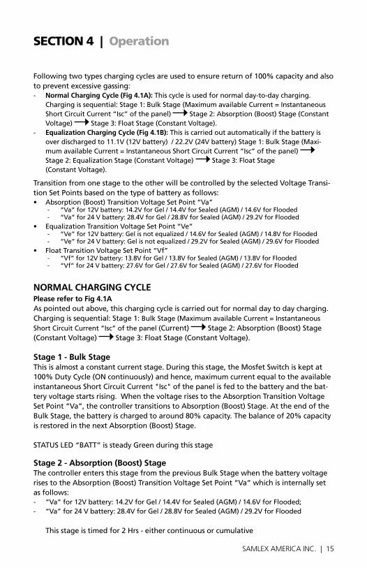
Fig 4.1A - Normal Charging Cycle (12V, Flooded)Bulk Absorption (Boost) Float
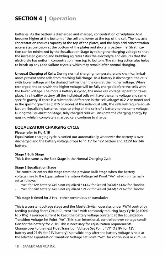
Fig 4.1B - Equalization Charging Cycle (12V, Flooded)Bulk Equalization Float
TIMEDAY
Vf
Ve
BA
TTE
RY
VO
LTA
GE
10
11
12
13
14
15
16 STAGE 1BULK
STAGE 2ABSORPTION
(BOOST)STAGE 3FLOAT
NIGHT NIGHT NIGHT NIGHTSTAGE 1
BULK
STAGE 2EQUALIZATION
STAGE 3FLOAT
14 | SAMLEX AMERICA INC. SAMLEX AMERICA INC. | 15
SeCtIOn 4 | Operation
following two types charging cycles are used to ensure return of 100% capacity and also to prevent excessive gassing: - NormalChargingCycle(fig4.1A):This cycle is used for normal day-to-day charging.
Charging is sequential: Stage 1: bulk Stage (Maximum available Current = Instantaneous Short Circuit Current “Isc” of the panel) Stage 2: Absorption (boost) Stage (Constant Voltage) Stage 3: float Stage (Constant Voltage).
- equalizationChargingCycle(fig4.1b):This is carried out automatically if the battery is over discharged to 11.1V (12V battery) / 22.2V (24V battery) Stage 1: bulk Stage (Maxi-mum available Current = Instantaneous Short Circuit Current “Isc” of the panel) Stage 2: equalization Stage (Constant Voltage) Stage 3: float Stage (Constant Voltage).
Transition from one stage to the other will be controlled by the selected Voltage Transi-tion Set Points based on the type of battery as follows:• Absorption(Boost)TransitionVoltageSetPoint“Va”
- “Va” for 12V battery: 14.2V for Gel / 14.4V for Sealed (AGM) / 14.6V for flooded- “Va” for 24 V battery: 28.4V for Gel / 28.8V for Sealed (AGM) / 29.2V for flooded
• EqualizationTransitionVoltageSetPoint“Ve”- “Ve” for 12V battery: Gel is not equalized / 14.6V for Sealed (AGM) / 14.8V for flooded- “Ve” for 24 V battery: Gel is not equalized / 29.2V for Sealed (AGM) / 29.6V for flooded
• FloatTransitionVoltageSetPoint“Vf”- “Vf” for 12V battery: 13.8V for Gel / 13.8V for Sealed (AGM) / 13.8V for flooded- “Vf” for 24 V battery: 27.6V for Gel / 27.6V for Sealed (AGM) / 27.6V for flooded
noRMAL cHARGinG cYcLePleaserefertofig4.1AAs pointed out above, this charging cycle is carried out for normal day to day charging. Charging is sequential: Stage 1: bulk Stage (Maximum available Current = Instantaneous Short Circuit Current “Isc” of the panel (Current) Stage 2: Absorption (boost) Stage (Constant Voltage) Stage 3: float Stage (Constant Voltage).
Stage1-bulkStageThis is almost a constant current stage. During this stage, the Mosfet Switch is kept at 100% Duty Cycle (oN continuously) and hence, maximum current equal to the available instantaneous Short Circuit Current "Isc" of the panel is fed to the battery and the bat-tery voltage starts rising. When the voltage rises to the Absorption Transition Voltage Set Point “Va”, the controller transitions to Absorption (boost) Stage. At the end of the bulk Stage, the battery is charged to around 80% capacity. The balance of 20% capacity is restored in the next Absorption (boost) Stage.
STATUS LeD “bATT” is steady Green during this stage
Stage2-Absorption(boost)StageThe controller enters this stage from the previous bulk Stage when the battery voltage rises to the Absorption (boost) Transition Voltage Set Point “Va” which is internally set as follows:- “Va” for 12V battery: 14.2V for Gel / 14.4V for Sealed (AGM) / 14.6V for flooded; - “Va” for 24 V battery: 28.4V for Gel / 28.8V for Sealed (AGM) / 29.2V for flooded
This stage is timed for 2 Hrs - either continuous or cumulative

16 | SAMLEX AMERICA INC.
SeCtIOn 4 | Operation
This is a constant voltage stage and the Mosfet Switch operates under PWM control by feeding pulsing Short Circuit Current “Isc” with constantly reducing Duty Cycle (< 100% to > 0%) / average current to keep the battery voltage constant at the Absorption Transition Voltage Set Point “Va”. This is an intentional, controlled over voltage condi-tion for the battery for 2 Hrs. This is necessary to return the balance 20% of the capacity. At this voltage, the battery starts gassing (evolution of Hydrogen and oxygen due to electrolysis of water in the electrolyte) and hence, it is necessary to exit this stage as soon as 100% capacity is restored. If this over voltage condition is allowed to continues after 100% recharging, the battery will be damaged due to effects of overcharging like overheating, loss of water, corrosion of the Positive plates and excessive build up of pressure resulting in acid spillage due to opening of pressure activated relief valves (sealed batteries). The balance of 20% of the battery capacity is restored in this stage. As the battery capacity rises from 80% to 100%, the PWM control tapers the current by continuously reducing the Duty Cycle from < 100% to > 0%.
Change over to the next float Transition Voltage Set Point “Vf” (13.8V for 12 V battery and 27.6V for 24V battery) is possible only after the battery voltage is held at the selected Absorption (boost) Transition Voltage Set Point “Va” for continuous or cumulative period of 2 Hours. If Absorption (boost) Transition Voltage Set Point “Va” cannot be maintained continuously / cumulatively for 2 Hr, transition to float Stage WiLL not take place. STATUS LeD “bATT” is steady Green during this stage
NoTe:DuringAbsorption(boost)Stage,iftheloadcurrentismorethanthecurrentfromthePvPanel(s),thebatteryvoltagewilldrop.Ifthebatteryvoltagedropsto13.2vfor12vbatteryand26.4vfor24vbattery,thecontrollerrevertstoStage1:bulkStage.PwmDuTyCycleischangedto100%andSTATuSleD“bATT”changestosteadyGreenthereafter.
Stage3-floatstageThe controller enters this stage from the previous Absorption (boost) Stage after the battery voltage is held at the selected Absorption (boost) Transition Voltage Set Point “Va” for continuous or cumulative period of 2 Hours.
This is also a constant voltage stage and the Mosfet Switch operates under PWM control by feeding pulsing, instantaneous Short Circuit Current “Isc” with very low Duty Cycle of > 0% to < 10% to keep the battery voltage constant at the float Transition Voltage Set Point “Vf” (13.8V for 12V battery and 27.6V for 24V battery). During this stage, the battery is 100% charged and a very low “Trickle Charge” of around 0.1% of the Ah Ca-pacity is required to be fed to the battery to compensate for self-discharge. The battery can be left at this stage for prolonged period of time.
STATUS LeD “bATT” is steady Green during this stage

16 | SAMLEX AMERICA INC. SAMLEX AMERICA INC. | 17
NoTe:DuringfloatStage,iftheloadcurrentismorethanthecurrentfromthePvPanel(s),thebatteryvoltagewilldrop.Ifthebatteryvoltagedropsto13.2vfor12vbat-teryand26.4vfor24vbattery,thecontrollerrevertstoStage1:bulkStage.PwmDuTyCycleischangedto100%andSTATuSleD“bATT”changestosteadyGreenthereafter.
eQUALizAtion oF LeAD AciD BAtteRieS - GeneRAL inFoRMAtion
WARninG!
RiSk oF exPLoSion AnD eQUiPMent DAMAGe!• Equalizingfloodedbatterycanproduceexplosivegases.Ensureproperventilationofthe
battery box • EqualizationmayincreasebatteryvoltagetothelevelthatcandamagesensitiveDC
loads. ensure that DC input voltage of all DC loads is greater than the equalizing Charging Set Point. DC loads not matching equalization Voltage Set Point should be disconnected.
! cAUtion!
• Topuptheelectrolytewithdistilledwateraftercompletionofequalization.• Excessiveoverchargingandgassingtoovigorouslycandamagethebatteryplatesand
cause shedding of active material from the plates. An equalization that is too high or for too long can be damaging. review the requirements for the particular battery being used in your system.
equalization is intentional overcharging of the battery for controlled period of time. routine equalization cycles are often vital to the performance and life of a battery — particularly in a solar system where peak sun hours per day are limited and variable and may not be sufficient to keep the battery in a fully charged condition. Periodic equali-zation is carried out for proper health and long life of a Lead Acid battery to prevent / reduce the following undesirable effects:
Sulfation:If the charging process is not complete due to inability of the charger to pro-vide the required voltage levels or if the battery is left uncharged for a long duration of time, soft Lead Sulfate crystals on the Positive and Negative plates that are formed during discharging / self discharge are not fully converted back to Lead Dioxide on the Positive plate and Sponge Lead on the Negative plate and get hardened and are diffi-cult to dislodge through normal charging. These crystals are non-conducting and hence, introduce increased internal resistance in the battery. This increased internal resistance introduces internal voltage drop during charging and discharging. Voltage drop during charging results in overheating and undercharging and formation of more Lead Sulfate crystals. Voltages drop on discharging results in overheating and excessive voltage drop in the terminal voltage of the battery. overall, this results in poor performance of the battery. Sulfation may be reduced partially by the stirring / mixing action of the electrolyte due to gassing and bubbling because of intentional overcharging during the equalization Stage.electrolyteStratification:electrolyte stratification can occur in all types of flooded
SeCtIOn 4 | Operation
18 | SAMLEX AMERICA INC.
SeCtIOn 4 | Operation
batteries. As the battery is discharged and charged, concentration of Sulphuric Acid becomes higher at the bottom of the cell and lower at the top of the cell. The low acid concentration reduces capacity at the top of the plates, and the high acid concentration accelerates corrosion at the bottom of the plates and shortens battery life. Stratifica-tion can be minimized by the equalization Stage by raising the charging voltage so that the increased gassing and bubbling agitates / stirs the electrolyte and ensures that the electrolyte has uniform concentration from top to bottom. The stirring action also helps to break up any Lead Sulfate crystals, which may remain after normal charging.
unequalChargingofCells:During normal charging, temperature and chemical imbal-ances prevent some cells from reaching full charge. As a battery is discharged, the cells with lower voltage will be drained further than the cells at the higher voltage. When recharged, the cells with the higher voltage will be fully charged before the cells with the lower voltage. The more a battery is cycled, the more cell voltage separation takes place. In a healthy battery, all the individual cells will have the same voltage and same specific gravity. If there is a substantial difference in the cell voltages (0.2 V or more) and in the specific gravities (0.015 or more) of the individual cells, the cells will require equal-ization. equalizing batteries helps to bring all the cells of a battery to the same voltage. During the equalization Stage, fully charged cells will dissipate the charging energy by gassing while incompletely charged cells continue to charge.
eQUALizAtion cHARGinG cYcLe Pleaserefertofig4.1bequalization charging cycle is carried out automatically whenever the battery is over discharged and the battery voltage drops to 11.1V for 12V battery and 22.2V for 24V battery. Stage1bulkStageThis is the same as the bulk Stage in the Normal Charging Cycle.
Stage2equalizationStageThe controller enters this stage from the previous bulk Stage when the battery voltage rises to the equalization Transition Voltage Set Point “Ve” which is internally set as follows:- “Ve” for 12V battery: Gel is not equalized / 14.6V for Sealed (AGM) / 14.8V for flooded- “Ve” for 24V battery: Gel is not equalized / 29.2V for Sealed (AGM) / 29.6V for flooded This stage is timed for 2 Hrs - either continuous or cumulative This is a constant voltage stage and the Mosfet Switch operates under PWM control by feeding pulsing Short Circuit Current “Isc” with constantly reducing Duty Cycle (< 100% to > 0%) / average current to keep the battery voltage constant at the equalization Transition Voltage Set Point “Ve”. This is an intentional, controlled over voltage condi-tion for the battery for 2 Hrs. This is necessary for equalization requirements. Change over to the next float Transition Voltage Set Point “Vf” (13.8V for 12V battery and 27.6V for 24V battery) is possible only after the battery voltage is held at the selected equalization Transition Voltage Set Point “Ve” for continuous or cumula-

18 | SAMLEX AMERICA INC. SAMLEX AMERICA INC. | 19
tive period of 2 Hours. If equalization Transition Voltage Set Point “Ve” cannot be maintained continuously / cumulatively for 2 Hr, transition to float Stage will NoT take place. STATUS LeD “bATT” is steady Green during this stage
NoTe:DuringequalizationStage,iftheloadcurrentismorethanthecurrentfromthePvPanel(s),thebatteryvoltagewilldrop.Ifthebatteryvoltagedropsto13.2vfor12vbatteryand26.4vfor24vbattery,thecontrollerrevertstoStage1:bulkStage.PwmDuTyCycleischangedto100%andSTATuSleD“bATT”changestosteadyGreenthereafter.
Stage3-floatstageThe controller enters this stage from the previous equalization Stage after the battery voltage is held at the selected equalization Transition Voltage Set Point “Ve” for con-tinuous or cumulative period of 2 Hours.
This stage is the same as the float Stage in the Normal Charging Cycle
LeD inDicAtionS
fig 4.2 LeD Indications
2. STATUS LeD “PV”
LeD coLoR & PAtteRn StAtUS
Green - Steady “cHARGinG”: energy from PV Panel(s) is available at the PV Panel(s) input terminals and voltage > 6V is also available simultaneously at the battery terminals.
Green - fast flashing “BAtteRY oVeR VoLtAGe”- over Voltage Disconnect protection has been activated due to high voltage of ≥ 16V / 32V at the battery output terminals- PV Panel(s) and Load have been disconnected
3. STATUS LeD “bATT”
SeCtIOn 4 | Operation
2 3 4 5 6
7

20 | SAMLEX AMERICA INC.
SeCtIOn 4 | Operation
LeD coLoR & PAtteRn StAtUS
Green - Steady “noRMAL”: battery is in bulk Stage - Normal State of Charge of up to 80%
Green - Slowly flashing “FULL”: battery is in either Absorption (boost) or equalization or float Stage and PWM regulated voltage charging is active. State of Charge is nearly full / completely full - 80% to 100%
orange - Steady “UnDeR VoLtAGe”: battery Under Voltage Warning Signaling has been activated at ≤ 12V / ≤ 24V. output is still available at Load Terminals- Will be reset automatically when voltage rises to 12.2V / 24.4V and LeD will go back to steady Green from steady orange
red - Steady “oVeR DiScHARGe”: Protection against over discharge of bat-tery has been activated at ≤ 11.1V / ≤ 22.2V and the load has been disconnected. - Load will be reconnected automatically at 12.6V / 25.2V and the LeD will go back to steady Green from steady red
4. StAtUS LeD “FLooDeD”: flooded type of battery has been selected
5. StAtUS LeD “GeL”: Sealed, Gel Cell type of battery gas been selected.
6. StAtUS LeD “SeALeD”: Sealed, AGM type of battery has been selected.
7. StAtUS LeD “LoAD” LoAD StAtUS inDicAtoR: Display the load status.
LeD coLoR & PAtteRn StAtUS
red - flashing
red - Steady
oVeR LoAD oR SHoRt ciRcUit”: Load has been disconnected due to overload or short circuit in the load circuit connected to the Load Terminals- overload: 12.5A for 5 sec – Manual reset by pressing “Set” button- ShortCircuit: 35A – first short circuit is reset automatically after 10 sec. Second consecutive short circuit will require manual reset by pressing “Set” button
Load in oN condition
overheatingProtectionIndication
LeD coLoR & PAtteRn StAtUS
Status LeDs “Sealed” (6), “Gel” (5) and “flooded” (4) flashing red simultaneously
Heat sink of the controller > 85°CInput and output circuits have been disconnectedWill reset automatically when temperature drops to < 75°C

20 | SAMLEX AMERICA INC. SAMLEX AMERICA INC. | 21
i
inFo
Please note that in some applications like in Portable Solar Charging Kits, solar panel(s) will be permanently connected to the input terminals of the Charge Controller and the battery will be connected whenever the Portable Charging Kit is required to be used. In these applications, the modules will start generating power as soon as these are ex-posed to sunlight. However, there will be no power output from the Charge Controller until the controller is connected to the battery. The following spurious LeD indications may be seen at the Charge Controller and may be disregarded:
Module(s) are exposed to Sunlight and battery has not been connected• NoLEDindication
Module(s) are exposed to Sunlight, battery is Connected and then removed. • “PV”LED: SteadyGreen• “BATT”LED: SteadyGreenwithRedflickering
SettinG BAtteRY tYPe AnD LoAD on/oFF contRoL
figure 4-3 Setting battery Type and Load oN / off Control
ControllingoN/offoperationofloadTerminalsWhen the controller is powered oN, press the Setting button (8) to toggle the load oN and off. When load is oN, Load Status LeD (7) will turn oN - reD.
batteryTypeSettingPress the Setting button (8) for more than 5 seconds, the original battery type indicator will be flashing. Then press the setting button to choose Sealed, Gel, and flooded battery type. The setting finishes when flashing stops.
SeCtIOn 4 | Operation
4 5 6
7
8

22 | SAMLEX AMERICA INC.
SeCtIOn 5 | Protections, troubleshooting & Maintenance
PRotectionS
PvArrayShortCircuitIf PV array short circuit occurs, clear it to resume normal operation.
overloadintheload(s)ConnectedtoloadTerminalsIf the load current exceeds the maximum load current rating, the controller will discon-nect the load. The greater the overload, the faster the load will be disconnected. A small overload could take a few minutes to disconnect. overloading must be removed by reapplying power or pressing the Setting button (8).
loadShortCircuitfully protected against load wiring short-circuit. After one automatic load reconnect at-tempt, the fault must be cleared by reapplying power or pressing the Setting button (8).
PvReversePolarityfully protected against PV reverse polarity. The controller will not be damaged. Correct polarity of the wiring to resume normal operation.
batteryReversePolarityfully protected against battery reverse polarity. The controller will not be damaged. Cor-rect polarity of wiring to resume normal operation.
DamagedlocalTemperatureSensorIf the temperature sensor is short-circuited or damaged, the controller will be charging or discharging at the default temperature of 25°C to prevent battery damage due to overcharging or over discharged.
overheatingProtectionIf the temperature of the controller’s heat sink exceeds 85°C, the input and output will be disconnected. Connection will be resumed at 75°C.
HighvoltageTransientsbattery is protected against high voltage transients. In lightning prone areas, additional external lightning protection is recommended.
TRoubleSHooTING-Pleaserefertothelayoutatfig2.1
Symptom PossibleCause Remarks/Remedy
Green Status LeD “PV” (2) is not lighted although solar panel(s) are exposed to sunlight
energy from solar panel(s) is not available at the Solar Panel Input Terminals of the controller. Voltage > 6V is not available simultaneously at the battery Terminals of the controller.
Check solar panel(s) wiring Check battery connection and series fuses and ensure voltage >6V is available at the battery terminals of the controller

22 | SAMLEX AMERICA INC. SAMLEX AMERICA INC. | 23
Symptom PossibleCause Remarks/Remedy
Status LeD “PV” (2) is Green - fast flashing and there is no output at the Load Terminals
battery over Voltage Discon-nect Protection has been activated due to high voltage of ≥ 16V / 32V at the bat-tery output terminals. Solar Panel(s) and Load have been disconnected
Disconnect the Solar panel(s) and discharge the battery
Status LeD “bATT” (3) is orange - Steady. output is available at the Load Terminals
battery Under Voltage Warning Signaling has been activated at ≤ 12V / ≤ 24V. output is still available at Load Terminals
Charge the battery. reduce / switch off load to allow the battery voltage to rise Will be reset automatically when voltage rises to 12.2V / 24.4V and LeD will go back to steady Green from steady orange
Status LeD “bATT” (3) is red - SteadyNo output voltage at the Load Terminals
Protection against over discharge of battery has been activated at ≤ 11.1V / ≤ 22.2V and the load has been discon-nected.
Charge the battery. reduce / switch off load to allow the battery voltage to rise:- Load will be reconnected automatically at 12.6V / 25.2V and the LeD will go back to steady Green from steady red
Status LeD “Load” (7)is red - flashing
Load has been disconnected due to overload or short circuit in the load circuit con-nected to the Load Terminals:- overload: 12.5A for 5 sec- Short Circuit: 35A –
remove the cause of overload / short circuit:- overload is reset manually by pressing the “Set” button (8)- first short circuit is reset automatically after 10 sec. Second consecutive short circuit will require manual reset by pressing “Set” button (8)
Status LeDs “Sealed” (6), “Gel” (5) and “flooded” (4) are flashing red simultaneously Input and output circuits have been disconnected
Heat sink of the controller > 85°C
Check reasons for overheating. Improve ventilation and ensure proper cool airflow over heat sink surface- Will reset automatically when the unit cools down and temperature drops to < 75°C
noteS: • NoleDindicator:measurebatteryvoltagewithmultimeter.minimum6visrequiredto
startupthecontroller.• NoStatusleDindicator“Pv”(2)withnormalconnection:measuretheinputvoltageofPv
Panel(s),theinputvoltagemustbehigherthanbatteryvoltage!
i
inFo
Please note that in some applications like in Portable Solar Charging Kits, solar panel(s) will be permanently connected to the input terminals of the Charge Controller and the battery will be connected whenever the Portable Charging Kit is required to be used. In these applications, the modules will start generating power as soon as these are exposed to sunlight. However, there will be no power output from the Charge Controller until the controller is connected to the battery.
SeCtIOn 5 | Protections, troubleshooting & Maintenance

24 | SAMLEX AMERICA INC.
The following spurious LeD indications may be seen at the Charge Controller and may be disregarded:Module(s) are exposed to Sunlight and battery has not been connected• No LeD indication
Module(s) are exposed to Sunlight, battery is Connected and then removed. • “PV” LeD (2): Steady Green• “bATT” LeD (3): Steady Green with red flickering
MAintenAnceThe following inspections and maintenance tasks are recommended for optimum controller performance:
- Check that the controller is securely mounted in a clean and dry environment.
- Check that air flow and ventilation around the controller is not blocked. Clear all dirt or fragments on the heat sink.
- Check all the exposed wires to make sure insulation is not damaged due to sunlight dam-age, frictional, wear, dryness, insects or rats etc. Maintain or replace the wires, if necessary.
- Tighten all the terminals. Inspect for loose, broken, or burnt wire connections.
- Confirm that all the system components are grounded tightly and correctly.
- Confirm that all the terminals have no corrosion, insulation damage, discoloration due to high temperature or burn damage.
- Tighten terminal screws to the suggested torque.
- Inspect for dirt, insects and corrosion and remove
- Check and confirm that lightning protection devices are good condition.
SeCtIOn 5 | Protections, troubleshooting & Maintenance
24 | SAMLEX AMERICA INC. SAMLEX AMERICA INC. | 25
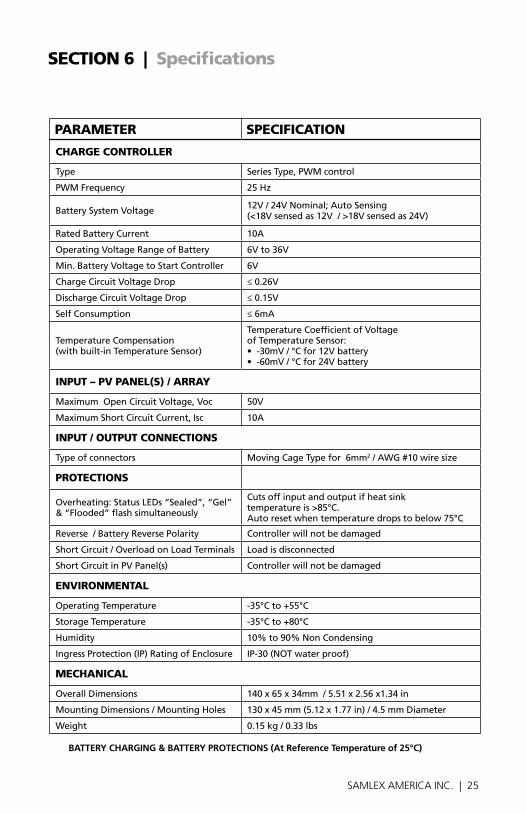
SeCtIOn 6 | Specifications
ParaMeter SPeCIFICatIOn
CharGe COntrOller
Type Series Type, PWM control
PWM frequency 25 Hz
battery System Voltage 12V / 24V Nominal; Auto Sensing (<18V sensed as 12V / >18V sensed as 24V)
rated battery Current 10A
operating Voltage range of battery 6V to 36V
Min. battery Voltage to Start Controller 6V
Charge Circuit Voltage Drop ≤ 0.26V
Discharge Circuit Voltage Drop ≤ 0.15V
Self Consumption ≤ 6mA
Temperature Compensation (with built-in Temperature Sensor)
Temperature Coefficient of Voltage of Temperature Sensor:•-30mV/°Cfor12Vbattery •-60mV/°Cfor24Vbattery
InPut – PV Panel(S) / array
Maximum open Circuit Voltage, Voc 50V
Maximum Short Circuit Current, Isc 10A
InPut / OutPut COnneCtIOnS
Type of connectors Moving Cage Type for 6mm2 / AWG #10 wire size
PrOteCtIOnS
overheating: Status LeDs “Sealed”, “Gel” & “flooded” flash simultaneously
Cuts off input and output if heat sink temperature is >85°C. Auto reset when temperature drops to below 75°C
reverse / battery reverse Polarity Controller will not be damaged
Short Circuit / overload on Load Terminals Load is disconnected
Short Circuit in PV Panel(s) Controller will not be damaged
enVIrOnMental
operating Temperature -35°C to +55°C
Storage Temperature -35°C to +80°C
Humidity 10% to 90% Non Condensing
Ingress Protection (IP) rating of enclosure IP-30 (NoT water proof)
MeChanICal
overall Dimensions 140 x 65 x 34mm / 5.51 x 2.56 x1.34 in
Mounting Dimensions / Mounting Holes 130 x 45 mm (5.12 x 1.77 in) / 4.5 mm Diameter
Weight 0.15 kg / 0.33 lbs
bATTeRyCHARGING&bATTeRyPRoTeCTIoNS(AtReferenceTemperatureof25°C)

26 | SAMLEX AMERICA INC.
PARAMeteRSealed(GelCell) Sealed(AGm) flooded
12V 24V 12V 24V 12V 24V
bulk Charge Current equal to Instantaneous Short Circuit Current Isc of the PV Panel(s) / Maximum 10A
Absorption (boost) Voltage 14.2V 28.4V 14.4V 28.8V 14.6V 29.2V
Absorption (boost) Duration 2 Hrs 2 Hrs 2 Hrs
float Voltage 13.8V 27.6V 13.8V 27.6V 13.8V 27.6V
equalization Voltage Not equalized 14.6V 29.2V 14.8V 29.6V
equalization Duration Not equalized 2 Hrs 2 Hrs
Automatic reset to bulk 13.2V 26.4V 13.2V 26.4V 13.2V 26.4V
Charging Limit Voltage [Disconnect PV Panel(s)] 15.5V 31.0V 15.5V 31.0V 15.5V 31V
over Voltage Disconnect:Disconnect PV Panel(s) and LoadIndication on Status LeD “PV”: Green - fast flashing
16.0V 32.0V 16.0V 32.0V 16.0V 32.0V
Activate Under Voltage Warning Signaling - Status LeD “bATT” turns orange from Green
12.0V 24.0V 12.0V 24.0V 12.0V 24.0V
reset Under Voltage Warning Signaling - Status LeD “bATT” goes back to Green from orange
12.2V 24.4V 12.2V 24.4V 12.2V 24.4V
Activate Protection Against over Discharge by disconnecting Load - Status LeD “bATT” turns red from Green
11.1V 22.2V 11.1V 22.2V 11.1V 22.2V
reset Protection Against over Discharge by reconnecting the load - Status LeD “bATT” goes back to Green from red
12.6V 25.2V 12.6V 25.2V 12.6V 25.2V
Discharging Limit Voltage 10.8V 21.6V 10.8V 21.6V 10.8V 21.6V
SeCtIOn 6 | Specifications

26 | SAMLEX AMERICA INC. SAMLEX AMERICA INC. | 27
SeCtIOn 7 | warranty
2 YeAR LiMiteD WARRAntY
MSK-10A Solar Charge Controller manufactured by Samlex America, Inc. (the “Warran-tor“) are warranted to be free from defects in workmanship and materials under normal use and service. The warranty period is 2 years for the United States and Canada, and is in effect from the date of purchase by the user (the “Purchaser“).
Warranty outside of the United States and Canada is limited to 6 months. for a warranty claim, the Purchaser should contact the place of purchase to obtain a return Authoriza-tion Number.
The defective part or unit should be returned at the Purchaser’s expense to the author-ized location. A written statement describing the nature of the defect, the date of pur-chase, the place of purchase, and the Purchaser’s name, address and telephone number should also be included.
If upon the Warrantor’s examination, the defect proves to be the result of defective material or workmanship, the equipment will be repaired or replaced at the Warran-tor’s option without charge, and returned to the Purchaser at the Warrantor’s expense. (Contiguous US and Canada only)
No refund of the purchase price will be granted to the Purchaser, unless the Warrantor is unable to remedy the defect after having a reasonable number of opportunities to do so. Warranty service shall be performed only by the Warrantor. Any attempt to remedy the defect by anyone other than the Warrantor shall render this warranty void. There shall be no warranty for defects or damages caused by faulty installation or hook-up, abuse or misuse of the equipment including exposure to excessive heat, salt or fresh water spray, or water immersion.
No other express warranty is hereby given and there are no warranties which extend beyond those described herein. This warranty is expressly in lieu of any other expressed or implied warranties, including any implied warranty of merchantability, fitness for the ordinary purposes for which such goods are used, or fitness for a particular purpose, or any other obligations on the part of the Warrantor or its employees and representatives.
There shall be no responsibility or liability whatsoever on the part of the Warrantor or its employees and representatives for injury to any persons, or damage to person or persons, or damage to property, or loss of income or profit, or any other consequential or resulting damage which may be claimed to have been incurred through the use or sale of the equipment, including any possible failure of malfunction of the equipment, or part thereof. The Warrantor assumes no liability for incidental or consequential dam-ages of any kind.
SamlexAmericaInc.(the“warrantor”)www.samlexamerica.com

Contact Information
Toll Free NumbersPh: 800 561 5885
Fax: 888 814 5210
Local NumbersPh: 604 525 3836
Fax: 604 525 5221
Websitewww.samlexamerica.com
USA Shipping WarehouseKent WA
Canadian Shipping WarehouseDelta BC
Email purchase orders [email protected]
11022-MSK-10A-Charge Controller-1013