solar photovoltaic (pv) system safety and fire ground ...ufsw.org/pdfs/photovoltaic_systems.pdf ·...
TRANSCRIPT
Solar Photovoltaic (PV)System Safety
andFire Ground Procedures
SAN FRANCISCO FIRE DEPARTMENT

blank page

Solar Photovoltaic (PV) System Safetyand Fire Ground Procedures
April 2012
San Francisco Fire Department698—2
ndStreet
San Francisco, CA 94107
Chief of DepartmentJoanne Hayes-White
Assistant Deputy Chief Jose Luis Velo, Director of Training
Project Manager, Paramedic Captain Jim PerryLieutenant Dawn Dewitt, Editor
Published by:Division of Training2310 Folsom StreetSan Francisco, CA
Phone: (415) 970-2000
April 2012This manual is the sole property of the San Francisco Fire Department
1
FOREWORD
The goal of this manual is to establish standard operating practices as authorized bythe Chief of Department and implemented by the Division of Training.
The purpose of this manual is to provide all members with the essential informationnecessary to fulfill the duties of their positions, and to provide a standard text wherebycompany officers can:
Enforce standard drill guidelines authorized as a basis of operation for allcompanies.
Align company drills to standards as adopted by the Division of Training. Maintain a high degree of proficiency, both personally and among their
subordinates.
All manuals shall be kept up to date so that all officers may use the material containedin the various manuals to meet the requirements of their responsibility.
Conditions will develop in fire fighting situations where standard methods of operationwill not be applicable. Therefore, nothing contained in these manuals shall beinterpreted as an obstacle to the experience, initiative, and ingenuity of officers inovercoming the complexities that exist under actual fire ground conditions.
To maintain the intent of standard guidelines and practices, no correction, modification,expansion, or other revision of this manual shall be made unless authorized by theChief of Department. Suggestions for correction, modification or expansion of thismanual shall be submitted to the Division of Training. Suggestions will be given dueconsideration, and if adopted, notice of their adoption and copies of the changes madewill be made available to all members by the Division of Training.
Joanne Hayes-WhiteChief of Department

2
blank page
i
Table of Contents
SECTION 1. SOLAR PV KEY SAFETY POINTS ..............................................1.1
SECTION 2. BACKGROUND/PURPOSE .........................................................2.1
SECTION 3. SOLAR SYSTEMS: “KNOWING THE DIFFERENCE”................3.1Solar Photovoltaic............................................................................................3.1Solar Thermal ..................................................................................................3.2Solar Co-generation.........................................................................................3.3
SECTION 4. SOLAR PV SYSTEM COMPONENTS .........................................4.1Photovoltaic Cell ..............................................................................................4.1Module/Array ...................................................................................................4.1Photovoltaic Inverters and Disconnects...........................................................4.2
Inverters ..................................................................................................4.3Disconnects.............................................................................................4.5
Electrical Conduit.............................................................................................4.6Interior Conduit........................................................................................4.6Exterior Conduit ......................................................................................4.7
Solar PV System Labeling ...............................................................................4.8
SECTION 5. THE PHOTOVOLTAIC SYSTEM: HOW IT WORKS!..................5.1Basic PV System Overview—“Grid-Tied” and Off-Grid”...................................5.1
“Grid-Tied” PV Systems ..........................................................................5.2Direct Grid-Tied PV Systems ..................................................................5.2Grid-Tied PV with Battery Back-up Storage System ...............................5.3“Off-Grid” PV System ..............................................................................5.5
Solar PV System Recognition..........................................................................5.6Roof-Mounted PV Systems.....................................................................5.6Building-Integrated PV Systems .............................................................5.8Ground Mounted PV Systems.................................................................5.9Other PV Systems...................................................................................5.10
Effects of Light on PV Systems .......................................................................5.11Sunlight/Daylight .....................................................................................5.11Nighttime.................................................................................................5.12
SECTION 6. PV SYSTEM HAZARDS AND FIREFIGHTER SAFETY...............6.1Electrical Shock and Effects of Electricity on the Body....................................6.1Burn Hazards...................................................................................................6.3Trip, Slip and/or Fall Hazard ............................................................................6.4Increased Roof Load Hazard...........................................................................6.5Hazardous Materials Inhalation Hazard...........................................................6.7PV System Battery Hazard ..............................................................................6.7
SECTION 7. INCIDENT PRIORITIES AND TACTICAL CONSIDERATIONS ...7.1Pre-Incident Identification ................................................................................7.1Communications..............................................................................................7.1Securing Utilities ..............................................................................................7.2Fire Attack Considerations...............................................................................7.3

ii
Ventilation Considerations...............................................................................7.3Salvage/Overhaul Considerations ...................................................................7.4
SECTION 8. SOLAR PHOTOVOLTAIC TERMINOLOGY/DEFINITIONS.........8.1
SECTION 9. MANUAL REFERENCES.............................................................9.1
SECTION 1. SOLAR PV KEY SAFETY POINTS
1.1
SECTION 1. SOLAR PV KEY SAFETYPOINTS
Daytime, Daylight = Danger Shock Hazard!!
Nighttime, Darkness = Potential Shock Hazard!!
During daylight hours the Solar PV modules (panels) are ENERGIZED and presenta potential electrical shock hazard. This is also true during overcast days! Useextreme caution when working around a PV system to minimize any potential ofelectrical shock!
During the nighttime/darkness, the Solar PV modules are generally not energizedand present minimal hazard from electrical shock. However, scene lighting, lowambient light, or other artificial light sources CAN generate enough voltage-currentto pose a shock hazard at night. The same safety precautions taken during the dayshould be taken in the darkness of night!
ALL Firefighters working around PV systems MUST be in full PPE including SCBA.
Never walk or climb on Solar PV modules. Although the modules will likelywithstand some weight load, they still present a significant safety hazard frombreaking glass, tripping and slipping. Exposure to the cells inside of the PVmodules presents a potential electrical shock hazard.
Never place roof or ridge ladders on or against the Solar PV modules/arrays.
Never break a Solar PV module (panel) with an axe or other forcible entry tool.
Do not attempt to remove a Solar PV module/array to perform firefighting duties.Leave the Solar modules/arrays in place and work around the system. If unable towork around the Solar PV array, notify the IC immediately. Alternative ventilationtactics should be considered.
Do not cut metal conduit or wires strung between Solar PV modules or wirescoming from a series of Solar PV modules to a combiner box. This could result inserious or fatal injury from electrical shock!
SECTION 2. SOLAR PV KEY SAFETY POINTS
1.2
Do not attempt to remove fuses from Solar PV fuse boxes. (Not all PV systemshave fuse boxes.) Doing so will likely start a fire and presents a significantelectrical shock hazard!
Stay clear of the Solar PV modules and conduit. Utilize walkways and PV systemclearances set by the installation requirements in San Francisco.
Secure the Main Electric Service Panel (Main Circuit Breaker Box) for the building.
Securing the main electric power coming into the building from PG&E will only shutdown power inside the building and does not stop the PV modules from producing DCpower when sunlight or a light source is present. An electric shock hazard still existsfrom the array to the DC side of the solar inverter.
SECTION 2. BACKGROUND/PURPOSE
2.1
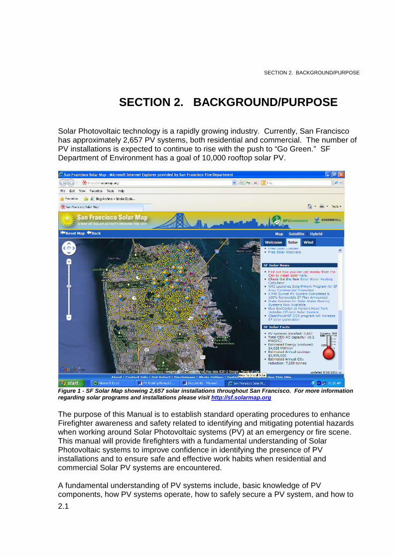
Solar Photovoltaic technology is a rapidly growing industry. Currently, San Franciscohas approximately 2,657 PV systems, both residential and commercial. The number ofPV installations is expected to continue to rise with the push to “Go Green.” SFDepartment of Environment has a goal of 10,000 rooftop solar PV.
Figure 1 - SF Solar Map showing 2,657 solar installations throughout San Francisco. For more informationregarding solar programs and installations please visit http://sf.solarmap.org
The purpose of this Manual is to establish standard operating procedures to enhanceFirefighter awareness and safety related to identifying and mitigating potential hazardswhen working around Solar Photovoltaic systems (PV) at an emergency or fire scene.This manual will provide firefighters with a fundamental understanding of SolarPhotovoltaic systems to improve confidence in identifying the presence of PVinstallations and to ensure safe and effective work habits when residential andcommercial Solar PV systems are encountered.
A fundamental understanding of PV systems include, basic knowledge of PVcomponents, how PV systems operate, how to safely secure a PV system, and how to
SECTION 2. BACKGROUND/PURPOSE
SECTION 2. BACKGROUND/PURPOSE
2.2
safely perform firefighting operations, such as fire attack and ventilation at anemergency or fire scene with a PV system.
Learning and remembering the Solar PV Key Safety Points, frequently referred tothroughout this training manual, will increase firefighter awareness and safety andlessen the potential for firefighter injuries or Line of Duty Death (LODD). CommonSolar PV terminology and definitions are listed in Appendix A at the end of this manual.
SECTION 3 SOLAR SYTEMS: "KNOWING THE DIFFERENCE"
3.1
While some people might think that all solar technology is the same, there are verydistinct differences between the three common types of solar system technology on themarket today. This section will identify the differences between Solar Photovoltaic,(referred to as PV or Solar Electric), Solar Thermal (Water-Heating) and Solar PVT(also known as cogeneration or combined systems). Firefighters will learn commonterminology, general function, solar components and potential hazards for each system.
SOLAR PHOTOVOLTAIC
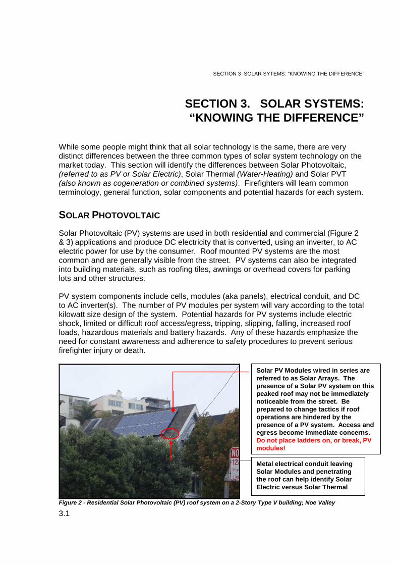
Solar Photovoltaic (PV) systems are used in both residential and commercial (Figure 2& 3) applications and produce DC electricity that is converted, using an inverter, to ACelectric power for use by the consumer. Roof mounted PV systems are the mostcommon and are generally visible from the street. PV systems can also be integratedinto building materials, such as roofing tiles, awnings or overhead covers for parkinglots and other structures.
PV system components include cells, modules (aka panels), electrical conduit, and DCto AC inverter(s). The number of PV modules per system will vary according to the totalkilowatt size design of the system. Potential hazards for PV systems include electricshock, limited or difficult roof access/egress, tripping, slipping, falling, increased roofloads, hazardous materials and battery hazards. Any of these hazards emphasize theneed for constant awareness and adherence to safety procedures to prevent seriousfirefighter injury or death.
Figure 2 - Residential Solar Photovoltaic (PV) roof system on a 2-Story Type V building; Noe Valley
SECTION 3. SOLAR SYSTEMS:“KNOWING THE DIFFERENCE”
Solar PV Modules wired in series arereferred to as Solar Arrays. Thepresence of a Solar PV system on thispeaked roof may not be immediatelynoticeable from the street. Beprepared to change tactics if roofoperations are hindered by thepresence of a PV system. Access andegress become immediate concerns.Do not place ladders on, or break, PVmodules!
Metal electrical conduit leavingSolar Modules and penetratingthe roof can help identify SolarElectric versus Solar Thermal
SECTION 3 SOLAR SYTEMS: "KNOWING THE DIFFERENCE"
3.2
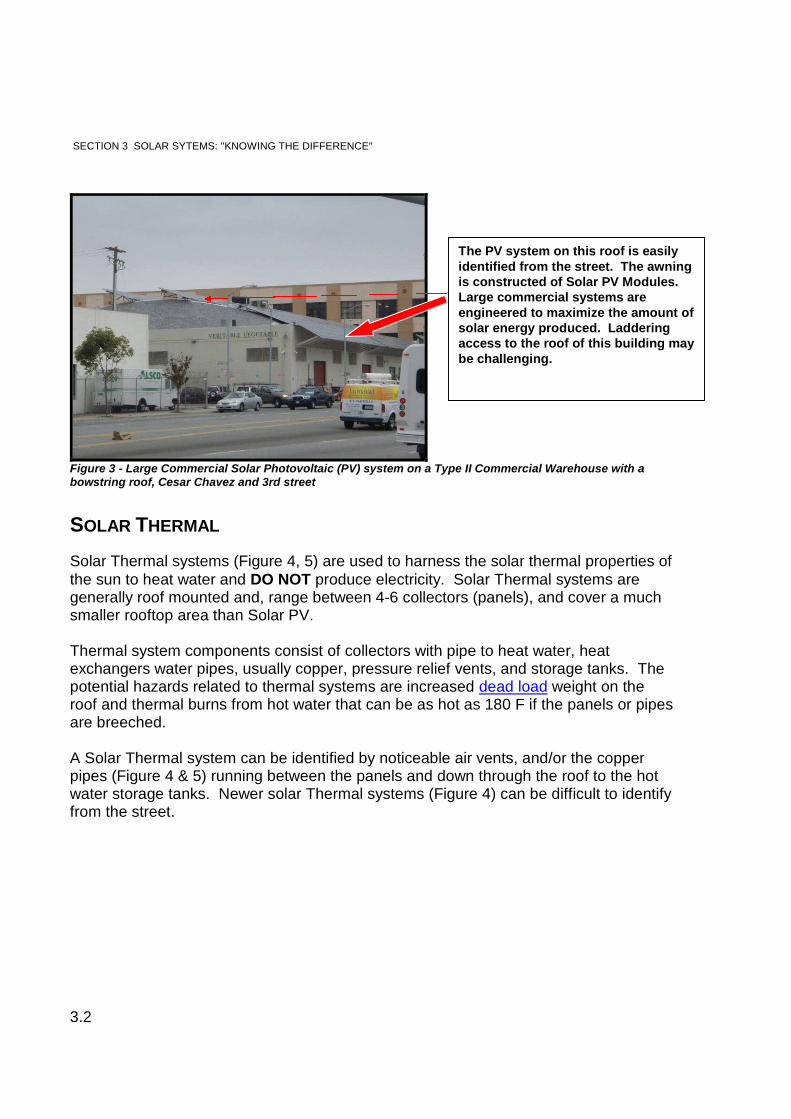
Figure 3 - Large Commercial Solar Photovoltaic (PV) system on a Type II Commercial Warehouse with abowstring roof, Cesar Chavez and 3rd street
SOLAR THERMAL
Solar Thermal systems (Figure 4, 5) are used to harness the solar thermal properties ofthe sun to heat water and DO NOT produce electricity. Solar Thermal systems aregenerally roof mounted and, range between 4-6 collectors (panels), and cover a muchsmaller rooftop area than Solar PV.
Thermal system components consist of collectors with pipe to heat water, heatexchangers water pipes, usually copper, pressure relief vents, and storage tanks. Thepotential hazards related to thermal systems are increased dead load weight on theroof and thermal burns from hot water that can be as hot as 180 F if the panels or pipesare breeched.
A Solar Thermal system can be identified by noticeable air vents, and/or the copperpipes (Figure 4 & 5) running between the panels and down through the roof to the hotwater storage tanks. Newer solar Thermal systems (Figure 4) can be difficult to identifyfrom the street.
The PV system on this roof is easilyidentified from the street. The awningis constructed of Solar PV Modules.Large commercial systems areengineered to maximize the amount ofsolar energy produced. Ladderingaccess to the roof of this building maybe challenging.
SECTION 3 SOLAR SYTEMS: "KNOWING THE DIFFERENCE"
3.3
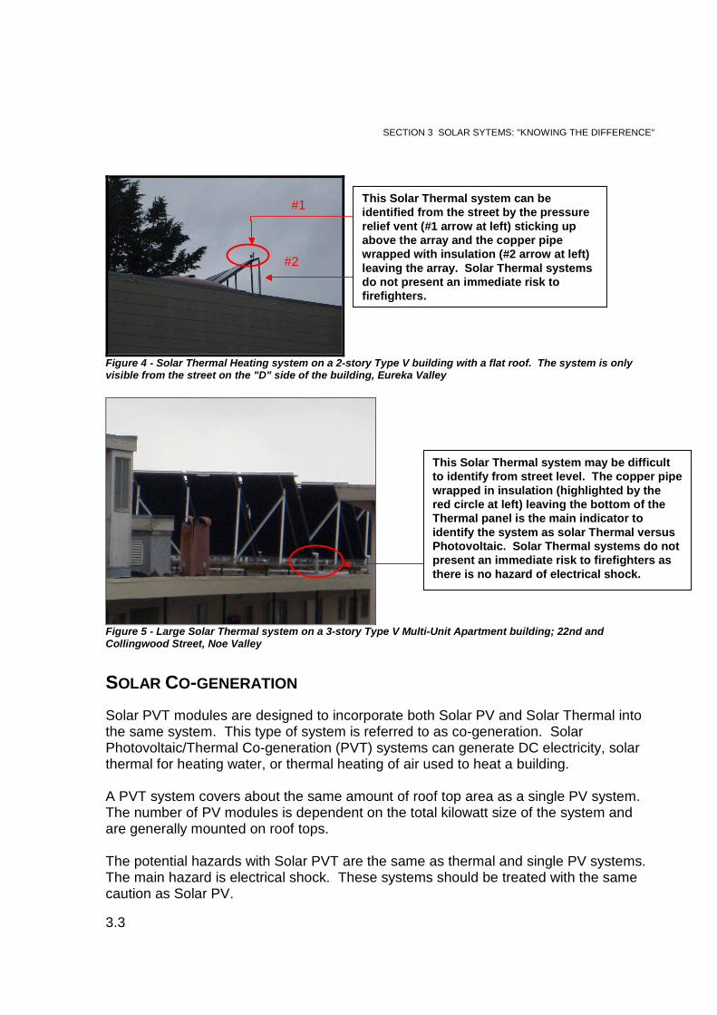
Figure 4 - Solar Thermal Heating system on a 2-story Type V building with a flat roof. The system is onlyvisible from the street on the "D" side of the building, Eureka Valley
Figure 5 - Large Solar Thermal system on a 3-story Type V Multi-Unit Apartment building; 22nd andCollingwood Street, Noe Valley
SOLAR CO-GENERATION
Solar PVT modules are designed to incorporate both Solar PV and Solar Thermal intothe same system. This type of system is referred to as co-generation. SolarPhotovoltaic/Thermal Co-generation (PVT) systems can generate DC electricity, solarthermal for heating water, or thermal heating of air used to heat a building.
A PVT system covers about the same amount of roof top area as a single PV system.The number of PV modules is dependent on the total kilowatt size of the system andare generally mounted on roof tops.
The potential hazards with Solar PVT are the same as thermal and single PV systems.The main hazard is electrical shock. These systems should be treated with the samecaution as Solar PV.
This Solar Thermal system can beidentified from the street by the pressurerelief vent (#1 arrow at left) sticking upabove the array and the copper pipewrapped with insulation (#2 arrow at left)leaving the array. Solar Thermal systemsdo not present an immediate risk tofirefighters.
#1
#2
This Solar Thermal system may be difficultto identify from street level. The copper pipewrapped in insulation (highlighted by thered circle at left) leaving the bottom of theThermal panel is the main indicator toidentify the system as solar Thermal versusPhotovoltaic. Solar Thermal systems do notpresent an immediate risk to firefighters asthere is no hazard of electrical shock.
SECTION 3 SOLAR SYTEMS: "KNOWING THE DIFFERENCE"
3.4
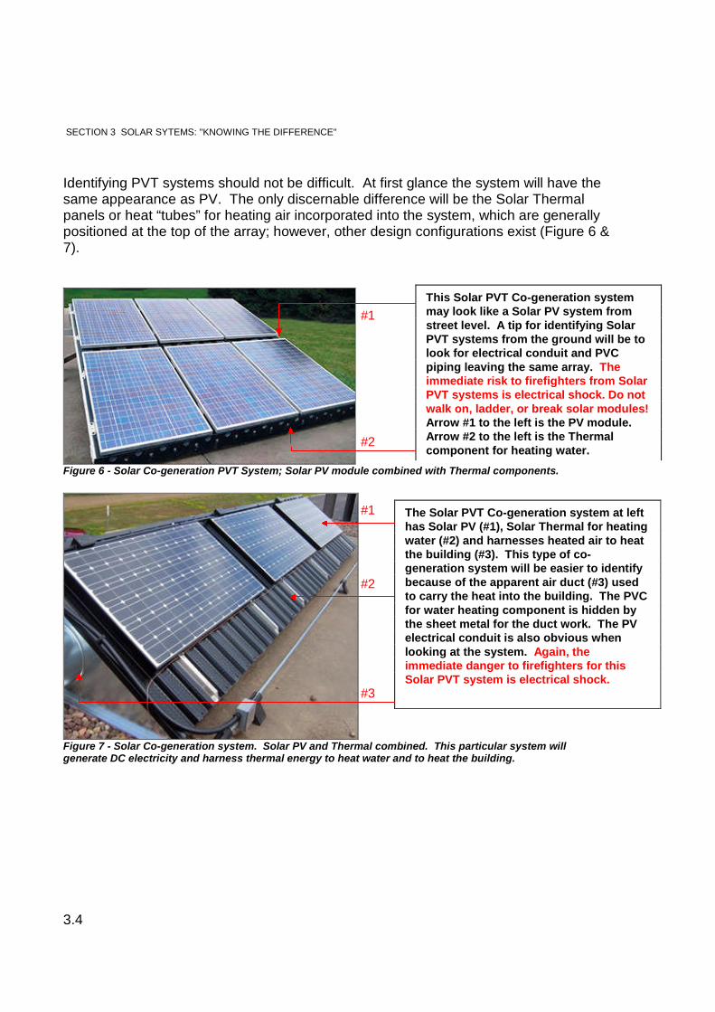
Identifying PVT systems should not be difficult. At first glance the system will have thesame appearance as PV. The only discernable difference will be the Solar Thermalpanels or heat “tubes” for heating air incorporated into the system, which are generallypositioned at the top of the array; however, other design configurations exist (Figure 6 &7).
Figure 6 - Solar Co-generation PVT System; Solar PV module combined with Thermal components.
Figure 7 - Solar Co-generation system. Solar PV and Thermal combined. This particular system willgenerate DC electricity and harness thermal energy to heat water and to heat the building.
This Solar PVT Co-generation systemmay look like a Solar PV system fromstreet level. A tip for identifying SolarPVT systems from the ground will be tolook for electrical conduit and PVCpiping leaving the same array. Theimmediate risk to firefighters from SolarPVT systems is electrical shock. Do notwalk on, ladder, or break solar modules!Arrow #1 to the left is the PV module.Arrow #2 to the left is the Thermalcomponent for heating water.
The Solar PVT Co-generation system at lefthas Solar PV (#1), Solar Thermal for heatingwater (#2) and harnesses heated air to heatthe building (#3). This type of co-generation system will be easier to identifybecause of the apparent air duct (#3) usedto carry the heat into the building. The PVCfor water heating component is hidden bythe sheet metal for the duct work. The PVelectrical conduit is also obvious whenlooking at the system. Again, theimmediate danger to firefighters for thisSolar PVT system is electrical shock.
#2
#1
#1
#2
#3
SECTION 3 SOLAR SYTEMS: "KNOWING THE DIFFERENCE"
3.5
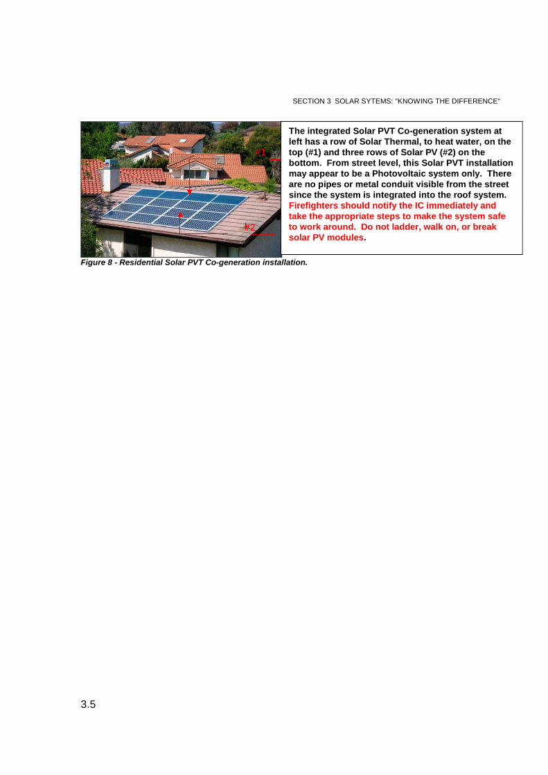
Figure 8 - Residential Solar PVT Co-generation installation.
The integrated Solar PVT Co-generation system atleft has a row of Solar Thermal, to heat water, on thetop (#1) and three rows of Solar PV (#2) on thebottom. From street level, this Solar PVT installationmay appear to be a Photovoltaic system only. Thereare no pipes or metal conduit visible from the streetsince the system is integrated into the roof system.Firefighters should notify the IC immediately andtake the appropriate steps to make the system safeto work around. Do not ladder, walk on, or breaksolar PV modules.
#1
#2

SECTION 4 SOLAR PV SYSTEM COMPONENTS
4.1
Solar Photovoltaic systems are designed to harness the maximum amount of solarenergy possible. Installation guidelines have been established by the Bureau of FirePrevention in coordination with the San Francisco Department of Building Inspection(DBI). A basic understanding of PV system components and installation requirementsin San Francisco will assist firefighters in recognizing the presence of a PV system.
This section will briefly identify and discuss PV components such as a PV cell, PVmodule/array, inverters, AC and DC disconnects electrical conduit, system labeling, andsolar battery storage. Firefighters with this basic knowledge will be able to quickly andconfidently identify PV components and learn the appropriate steps to safely secureand work around a PV system.
PHOTOVOLTAIC CELL
A Photovoltaic cell is the smallest part of a PV system. However, the PV cell is themost important part in terms of gathering solar energy produced by the sun (photons).There are two basic types of Photovoltaic semi-conductor cells: silicon and amorphoussilicon. In most cases, the semi-conductor silicon is approximately 1/100th of an inch inthickness.
The basic function of a PV cell is to collect photons from the sun to energize and forceelectrons from a negative layer to a positive layer in the PV cell. The process ofharnessing photons and forcing electrons from the negative to positive layers generatesaround .5 volts of solar energy per PV cell. Generally, semi-conductor cells are cut andcast together into a thin multi-crystalline construction, then fused and sandwiched insidea PV module. A PV module has many cells that work together to generate solarenergy.
MODULE/ARRAY
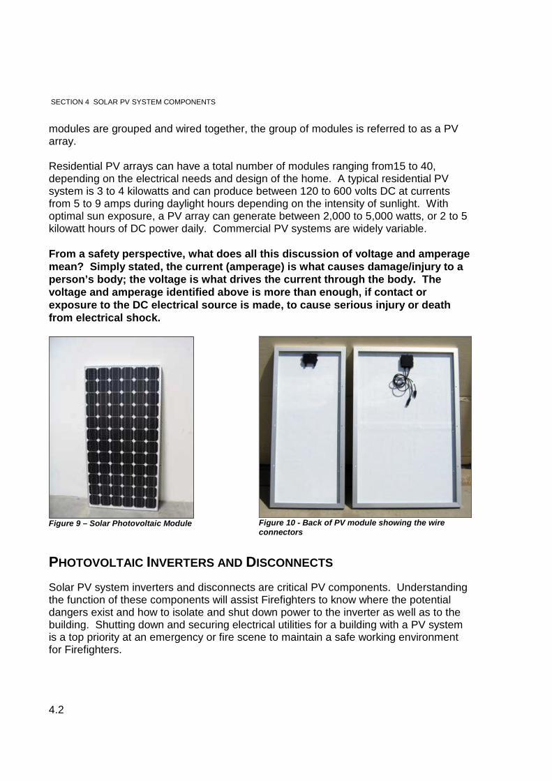
Solar PV modules (also known as panels) are designed to harness DC electricity fromsunlight. A module has no moving parts and is weatherproof. Photovoltaic modulesconsist of numerous PV cells wired together, enclosed in an aluminum frame, andcovered with tempered glass. Although the modules can range in size, typically eachmodule is 30” wide X 50” long, weighs between 30 to 50 pounds, and consists of 50 to72 semi-conductor cells. Solar PV modules are generally rated between 125 to 300watts and can produce 20 to 50 volts of DC power. Solar PV modules are normallygrouped and wired in series and parallel to increase voltage and amperage. When PV
SECTION 4. SOLAR PV SYSTEMCOMPONENTS
SECTION 4 SOLAR PV SYSTEM COMPONENTS
4.2
modules are grouped and wired together, the group of modules is referred to as a PVarray.
Residential PV arrays can have a total number of modules ranging from15 to 40,depending on the electrical needs and design of the home. A typical residential PVsystem is 3 to 4 kilowatts and can produce between 120 to 600 volts DC at currentsfrom 5 to 9 amps during daylight hours depending on the intensity of sunlight. Withoptimal sun exposure, a PV array can generate between 2,000 to 5,000 watts, or 2 to 5kilowatt hours of DC power daily. Commercial PV systems are widely variable.
From a safety perspective, what does all this discussion of voltage and amperagemean? Simply stated, the current (amperage) is what causes damage/injury to aperson’s body; the voltage is what drives the current through the body. Thevoltage and amperage identified above is more than enough, if contact orexposure to the DC electrical source is made, to cause serious injury or deathfrom electrical shock.
Figure 9 – Solar Photovoltaic Module Figure 10 - Back of PV module showing the wireconnectors
PHOTOVOLTAIC INVERTERS AND DISCONNECTS
Solar PV system inverters and disconnects are critical PV components. Understandingthe function of these components will assist Firefighters to know where the potentialdangers exist and how to isolate and shut down power to the inverter as well as to thebuilding. Shutting down and securing electrical utilities for a building with a PV systemis a top priority at an emergency or fire scene to maintain a safe working environmentfor Firefighters.
SECTION 4 SOLAR PV SYSTEM COMPONENTS
4.3
Inverters
Typical household fixtures and appliances utilize AC power to operate. Since PV arraysgenerate DC power, it must be converted to AC power before it can be used by theconsumer. An inverter converts the DC electricity from the PV array to AC electricitywhich is fed into the Main Electrical Service Panel (Circuit Breakers) for the building.There are a variety of inverter styles and sizes. The two types of inverters used for PVinstallations are system inverters and micro-inverters.
System inverters (also referred to as String inverters) are the traditional and mostcommon type of inverter used for solar PV systems to date. PV system inverters arerated and designed to receive a specific amount of DC voltage from multiple PVmodules in the array, and toconvert that power to AC electricity. A Solar PV systemmay require one or more inverters depending on the total kilowatt per hour design of thesystem, which determines the potential amount of DC voltage generated by the array.
System inverters are generally large and can be located inside and/or outside of abuilding depending on available space. In order to operate and convert DC power toAC power, system inverters require a dedicated AC electrical circuit wired from the MainElectrical Service Panel. The dedicated AC circuit for the inverter(s) is a built-in safetydesign to prevent the potential of electrical power being back fed into the PG&E utilitygrid in the event of a power outage.
The dedicated circuit for the inverter(s) also provides Firefighters with the abilityto quickly isolate converted AC electricity coming into the building from theinverter(s) by shutting down and securing all of the circuit breakers located at theMain Electrical Service Panel. However, this means that DC electricity is stillpresent in the electrical lines and conduit from the PV modules/array down to theDC line side of the inverter(s).
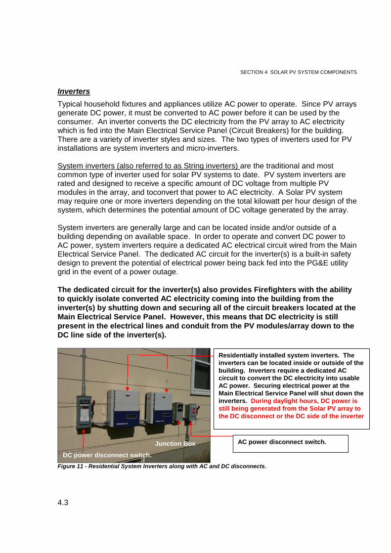
Figure 11 - Residential System Inverters along with AC and DC disconnects.
DC power disconnect switch.
Junction Box AC power disconnect switch.
Residentially installed system inverters. Theinverters can be located inside or outside of thebuilding. Inverters require a dedicated ACcircuit to convert the DC electricity into usableAC power. Securing electrical power at theMain Electrical Service Panel will shut down theinverters. During daylight hours, DC power isstill being generated from the Solar PV array tothe DC disconnect or the DC side of the inverter
SECTION 4 SOLAR PV SYSTEM COMPONENTS
4.4
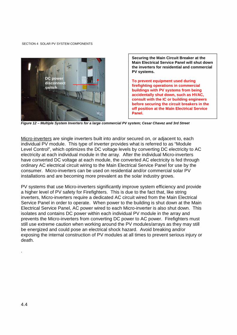
Figure 12 – Multiple System Inverters for a large commercial PV system; Cesar Chavez and 3rd Street
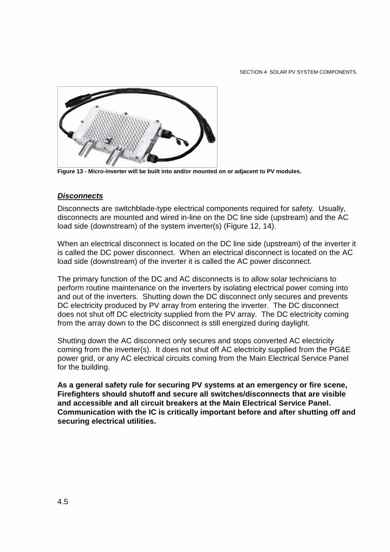
Micro-inverters are single inverters built into and/or secured on, or adjacent to, eachindividual PV module. This type of inverter provides what is referred to as “ModuleLevel Control”, which optimizes the DC voltage levels by converting DC electricity to ACelectricity at each individual module in the array. After the individual Micro-invertershave converted DC voltage at each module, the converted AC electricity is fed throughordinary AC electrical circuit wiring to the Main Electrical Service Panel for use by theconsumer. Micro-inverters can be used on residential and/or commercial solar PVinstallations and are becoming more prevalent as the solar industry grows.
PV systems that use Micro-inverters significantly improve system efficiency and providea higher level of PV safety for Firefighters. This is due to the fact that, like stringinverters, Micro-inverters require a dedicated AC circuit wired from the Main ElectricalService Panel in order to operate. When power to the building is shut down at the MainElectrical Service Panel, AC power wired to each Micro-inverter is also shut down. Thisisolates and contains DC power within each individual PV module in the array andprevents the Micro-inverters from converting DC power to AC power. Firefighters muststill use extreme caution when working around the PV modules/arrays as they may stillbe energized and could pose an electrical shock hazard. Avoid breaking and/orexposing the internal construction of PV modules at all times to prevent serious injury ordeath.
.
Securing the Main Circuit Breaker at theMain Electrical Service Panel will shut downthe inverters for residential and commercialPV systems.
To prevent equipment used duringfirefighting operations in commercialbuildings with PV systems from beingaccidentally shut down, such as HVAC,consult with the IC or building engineersbefore securing the circuit breakers in theoff position at the Main Electrical ServicePanel.
DC powerdisconnectswitch
SECTION 4 SOLAR PV SYSTEM COMPONENTS
4.5
Figure 13 - Micro-inverter will be built into and/or mounted on or adjacent to PV modules.
Disconnects
Disconnects are switchblade-type electrical components required for safety. Usually,disconnects are mounted and wired in-line on the DC line side (upstream) and the ACload side (downstream) of the system inverter(s) (Figure 12, 14).
When an electrical disconnect is located on the DC line side (upstream) of the inverter itis called the DC power disconnect. When an electrical disconnect is located on the ACload side (downstream) of the inverter it is called the AC power disconnect.
The primary function of the DC and AC disconnects is to allow solar technicians toperform routine maintenance on the inverters by isolating electrical power coming intoand out of the inverters. Shutting down the DC disconnect only secures and preventsDC electricity produced by PV array from entering the inverter. The DC disconnectdoes not shut off DC electricity supplied from the PV array. The DC electricity comingfrom the array down to the DC disconnect is still energized during daylight.
Shutting down the AC disconnect only secures and stops converted AC electricitycoming from the inverter(s). It does not shut off AC electricity supplied from the PG&Epower grid, or any AC electrical circuits coming from the Main Electrical Service Panelfor the building.
As a general safety rule for securing PV systems at an emergency or fire scene,Firefighters should shutoff and secure all switches/disconnects that are visibleand accessible and all circuit breakers at the Main Electrical Service Panel.Communication with the IC is critically important before and after shutting off andsecuring electrical utilities.
SECTION 4 SOLAR PV SYSTEM COMPONENTS
4.6
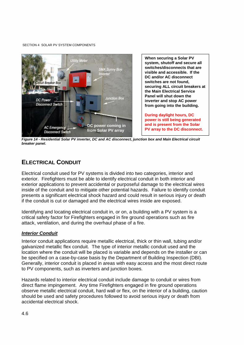
Figure 14 - Residential Solar PV inverter, DC and AC disconnect, junction box and Main Electrical circuitbreaker panel.
ELECTRICAL CONDUIT
Electrical conduit used for PV systems is divided into two categories, interior andexterior. Firefighters must be able to identify electrical conduit in both interior andexterior applications to prevent accidental or purposeful damage to the electrical wiresinside of the conduit and to mitigate other potential hazards. Failure to identify conduitpresents a significant electrical shock hazard and could result in serious injury or deathif the conduit is cut or damaged and the electrical wires inside are exposed.
Identifying and locating electrical conduit in, or on, a building with a PV system is acritical safety factor for Firefighters engaged in fire ground operations such as fireattack, ventilation, and during the overhaul phase of a fire.
Interior Conduit
Interior conduit applications require metallic electrical, thick or thin wall, tubing and/orgalvanized metallic flex conduit. The type of interior metallic conduit used and thelocation where the conduit will be placed is variable and depends on the installer or canbe specified on a case-by-case basis by the Department of Building Inspection (DBI).Generally, interior conduit is placed in areas with easy access and the most direct routeto PV components, such as inverters and junction boxes.
Hazards related to interior electrical conduit include damage to conduit or wires fromdirect flame impingement. Any time Firefighters engaged in fire ground operationsobserve metallic electrical conduit, hard wall or flex, on the interior of a building, cautionshould be used and safety procedures followed to avoid serious injury or death fromaccidental electrical shock.
When securing a Solar PVsystem, shutoff and secure allswitches/disconnects that arevisible and accessible. If theDC and/or AC disconnectswitches are not found,securing ALL circuit breakers atthe Main Electrical ServicePanel will shut down theinverter and stop AC powerfrom going into the building.
During daylight hours, DCpower is still being generatedand is present from the SolarPV array to the DC disconnect.
DC power coming infrom Solar PV array
SECTION 4 SOLAR PV SYSTEM COMPONENTS
4.7
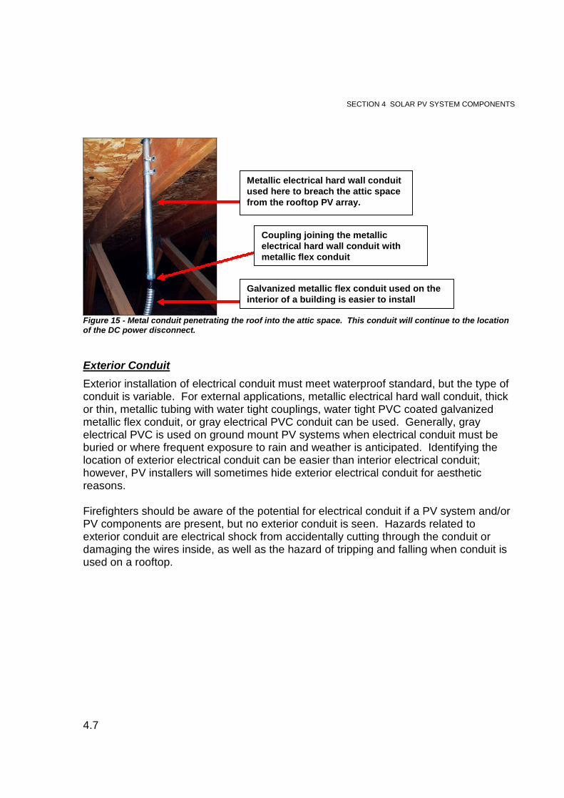
Figure 15 - Metal conduit penetrating the roof into the attic space. This conduit will continue to the locationof the DC power disconnect.
Exterior Conduit
Exterior installation of electrical conduit must meet waterproof standard, but the type ofconduit is variable. For external applications, metallic electrical hard wall conduit, thickor thin, metallic tubing with water tight couplings, water tight PVC coated galvanizedmetallic flex conduit, or gray electrical PVC conduit can be used. Generally, grayelectrical PVC is used on ground mount PV systems when electrical conduit must beburied or where frequent exposure to rain and weather is anticipated. Identifying thelocation of exterior electrical conduit can be easier than interior electrical conduit;however, PV installers will sometimes hide exterior electrical conduit for aestheticreasons.
Firefighters should be aware of the potential for electrical conduit if a PV system and/orPV components are present, but no exterior conduit is seen. Hazards related toexterior conduit are electrical shock from accidentally cutting through the conduit ordamaging the wires inside, as well as the hazard of tripping and falling when conduit isused on a rooftop.
Coupling joining the metallicelectrical hard wall conduit withmetallic flex conduit
Galvanized metallic flex conduit used on theinterior of a building is easier to install
Metallic electrical hard wall conduitused here to breach the attic spacefrom the rooftop PV array.
SECTION 4 SOLAR PV SYSTEM COMPONENTS
4.8
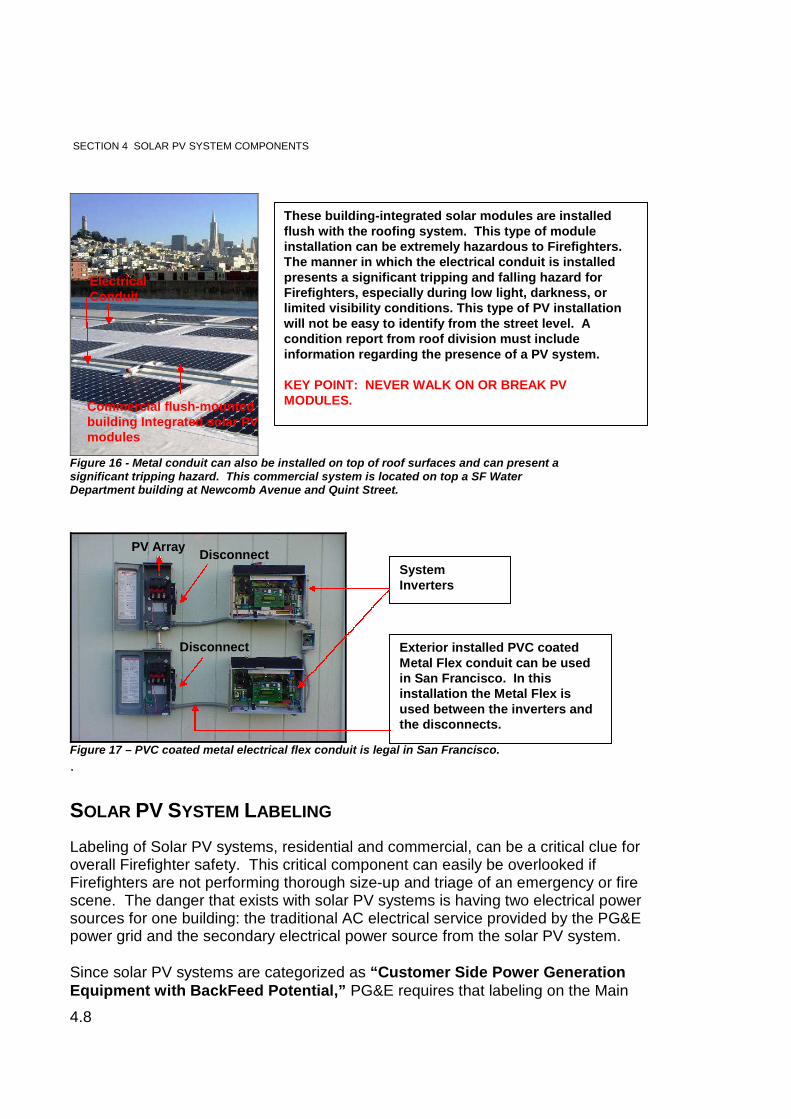
Figure 16 - Metal conduit can also be installed on top of roof surfaces and can present asignificant tripping hazard. This commercial system is located on top a SF WaterDepartment building at Newcomb Avenue and Quint Street.
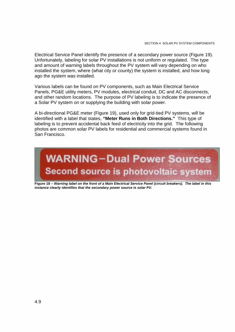
Figure 17 – PVC coated metal electrical flex conduit is legal in San Francisco.
.
SOLAR PV SYSTEM LABELING
Labeling of Solar PV systems, residential and commercial, can be a critical clue foroverall Firefighter safety. This critical component can easily be overlooked ifFirefighters are not performing thorough size-up and triage of an emergency or firescene. The danger that exists with solar PV systems is having two electrical powersources for one building: the traditional AC electrical service provided by the PG&Epower grid and the secondary electrical power source from the solar PV system.
Since solar PV systems are categorized as “Customer Side Power GenerationEquipment with BackFeed Potential,” PG&E requires that labeling on the Main
These building-integrated solar modules are installedflush with the roofing system. This type of moduleinstallation can be extremely hazardous to Firefighters.The manner in which the electrical conduit is installedpresents a significant tripping and falling hazard forFirefighters, especially during low light, darkness, orlimited visibility conditions. This type of PV installationwill not be easy to identify from the street level. Acondition report from roof division must includeinformation regarding the presence of a PV system.
KEY POINT: NEVER WALK ON OR BREAK PVMODULES.
ElectricalConduit
Commercial flush-mountedbuilding Integrated solar PVmodules
Exterior installed PVC coatedMetal Flex conduit can be usedin San Francisco. In thisinstallation the Metal Flex isused between the inverters andthe disconnects.
SystemInverters
DisconnectPV Array
Disconnect
SECTION 4 SOLAR PV SYSTEM COMPONENTS
4.9
Electrical Service Panel identify the presence of a secondary power source (Figure 19).Unfortunately, labeling for solar PV installations is not uniform or regulated. The typeand amount of warning labels throughout the PV system will vary depending on whoinstalled the system, where (what city or county) the system is installed, and how longago the system was installed.
Various labels can be found on PV components, such as Main Electrical ServicePanels, PG&E utility meters, PV modules, electrical conduit, DC and AC disconnects,and other random locations. The purpose of PV labeling is to indicate the presence ofa Solar PV system on or supplying the building with solar power.
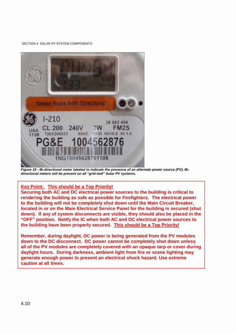
A bi-directional PG&E meter (Figure 19), used only for grid-tied PV systems, will beidentified with a label that states, “Meter Runs in Both Directions.” This type oflabeling is to prevent accidental back feed of electricity into the grid. The followingphotos are common solar PV labels for residential and commercial systems found inSan Francisco.
Figure 18 – Warning label on the front of a Main Electrical Service Panel (circuit breakers). The label in thisinstance clearly identifies that the secondary power source is solar PV.
SECTION 4 SOLAR PV SYSTEM COMPONENTS
4.10
Figure 19 - Bi-directional meter labeled to indicate the presence of an alternate power source (PV). Bi-directional meters will be present on all “grid-tied” Solar PV systems.
Key Point: This should be a Top Priority!Securing both AC and DC electrical power sources to the building is critical torendering the building as safe as possible for Firefighters. The electrical powerto the building will not be completely shut down until the Main Circuit Breaker,located in or on the Main Electrical Service Panel for the building is secured (shutdown). If any of system disconnects are visible, they should also be placed in the“OFF” position. Notify the IC when both AC and DC electrical power sources tothe building have been properly secured. This should be a Top Priority!
Remember, during daylight, DC power is being generated from the PV modulesdown to the DC disconnect. DC power cannot be completely shut down unlessall of the PV modules are completely covered with an opaque tarp or cover duringdaylight hours. During darkness, ambient light from fire or scene lighting maygenerate enough power to present an electrical shock hazard. Use extremecaution at all times.
SECTION 4 SOLAR PV SYSTEM COMPONENTS
4.11
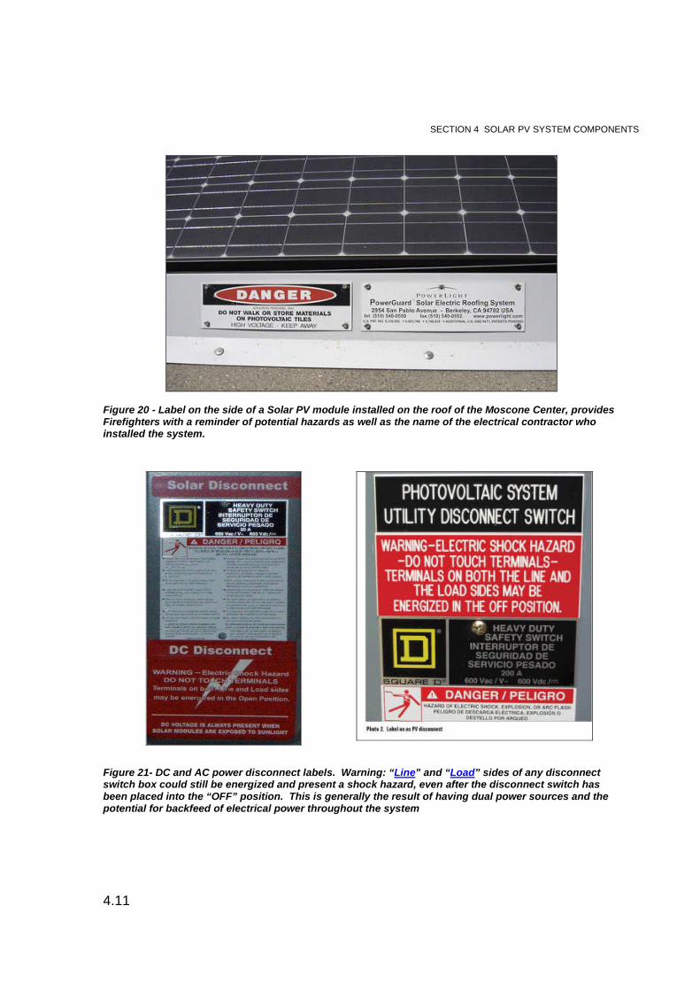
Figure 20 - Label on the side of a Solar PV module installed on the roof of the Moscone Center, providesFirefighters with a reminder of potential hazards as well as the name of the electrical contractor whoinstalled the system.
Figure 21- DC and AC power disconnect labels. Warning: “Line” and “Load” sides of any disconnectswitch box could still be energized and present a shock hazard, even after the disconnect switch hasbeen placed into the “OFF” position. This is generally the result of having dual power sources and thepotential for backfeed of electrical power throughout the system

SECTION 5 THE PHOTOVOLTAIC SYSTEM: HOW IT WORKS
5.1
While every building is different, PV systems are functionally the same. The technologyutilizes a basic process to produce and convert solar power for use by both residentialand commercial consumers. Each of the PV components has a specific job; whencombined with each other the PV system will harness the highest amount of solarpower possible.
This section will bring all of the components together in one unit to provide a betterunderstanding of the technology and operation of “grid-tied” and “off-grid” PV systems,battery back-up and storage, how daytime and nighttime light affects PV systems, andto improve recognition of different PV designs and installations. The differences in PVdesign and installation are based on individual consumer electrical needs, how the solarelectricity will be used or stored, and whether the system will be residentially orcommercially installed.
Knowing the difference between the system types determines what optional PVcomponents might be installed and is an important safety factor for Firefighters. Abasic knowledge of how solar PV systems work will help Firefighters understand wherethe potential hazards exist and how to reduce close-call injuries or Line of Duty Death(LODD).
BASIC PV SYSTEM OVERVIEW—“GRID-TIED” AND OFF-GRID”
The amount of DC electricity generated by a solar PV system is variable. Solar PVsystems are dependent on the atmospheric conditions and the condition ofinterconnected PV components in order to operate correctly and at optimal efficiency.The time of day, the amount of direct and indirect sunlight on the array, cloud cover,shade, shadows, and the mechanical condition, location, and proper installation of PVcomponents are examples of factors that directly affect the overall operation andperformance of a solar PV system.
The basic function and operation of how Solar PV systems harness energy fromsunlight to produce electricity is the same; Sunlight is converted to DC electricity bysolar cells and DC electricity is converted to AC electricity using an inverter. The onlydifference from one PV system to the next is design. PV system design is divided intotwo categories, grid-tied and off-grid. In order to determine the most suitable PVsystem for a specific consumer, the design is based, in part, on individual consumerelectrical needs and objectives and overall cost.
SECTION 5. THE PHOTOVOLTAICSYSTEM: HOW IT WORKS!
SECTION 5 THE PHOTOVOLTAIC SYSTEM: HOW IT WORKS
5.2
“Grid-Tied” PV Systems
The term “grid-tied” refers to alternative solar photovoltaic electrical power being usedin combination with traditional electrical power supplied by the PG&E utility power grid.For most consumers, a grid-tied PV system is the ideal configuration. Consumers get allthe benefits of using their own solar electricity as well as the benefits of beingconnected to the PG&E power grid. There are two design styles for grid-tied PVsystems, direct and battery back-up.
A direct grid-tied system is the basic style design for grid-tied PV. Consumers do havethe option to upgrade the system with battery back-up to mitigate power outages. Thebasic operation and design difference between direct grid-tied PV and a grid-tiedbattery back-up system is discussed below.
Direct Grid-Tied PV Systems
The most common PV system Firefighters will encounter in San Francisco is a directgrid-tied system. A grid-tied PV system is connected directly to the PG&E utility powergrid. This allows AC power to flow both into and out of the building through a bi-directional meter on the Main Electrical Service Panel. The amount of AC power beingsupplied into or out the building depends on the electrical needs of building occupantsand the amount of electrical power produced by the PV system at that exact time.
When the PV system is producing adequate solar electricity, the building only utilizessolar power. This is the PV system’s first priority. During times when the PV systemcannot produce enough solar electricity or is not producing solar electricity at all, suchas at night, the building electrical service will utilize power from the PG&E grid.
When the PV system is producing more solar electricity than the building occupants canuse, the excess is fed back through the bi-directional meter into the PG&E power grid.This is known as net-metering. With net-metering, when a consumer uses electricityfrom the PG&E grid, the bi-directional meter spins forward. When the consumer-basedPV system is producing excess solar electricity and feeding power into the PG&E powergrid, the bi-directional meter spins backwards. The offset means that consumers withPV systems are actually receiving market rates for the amount of electricity fed into thePG&E grid.
The downfall of direct grid-tied PV systems occurs during power outages. As discussedearlier, PV inverters require a dedicated AC circuit to convert DC voltage into usable ACvoltage. When the PG&E grid has a power outage, the inverter also loses power andcannot convert DC electricity into AC electricity for the duration of the outage. This is abuilt-in safety design to prevent back feeding of DC electricity through the system andinto the power grid. AC electrical power to the building will be restored after the PG&Egrid power is restored. This will occur regardless of the time of day.
**Safety Point: If the power outage occurs during daylight, the solar PV array isstill producing DC voltage. Therefore, DC electricity will be present at the arrays
SECTION 5 THE PHOTOVOLTAIC SYSTEM: HOW IT WORKS
5.3
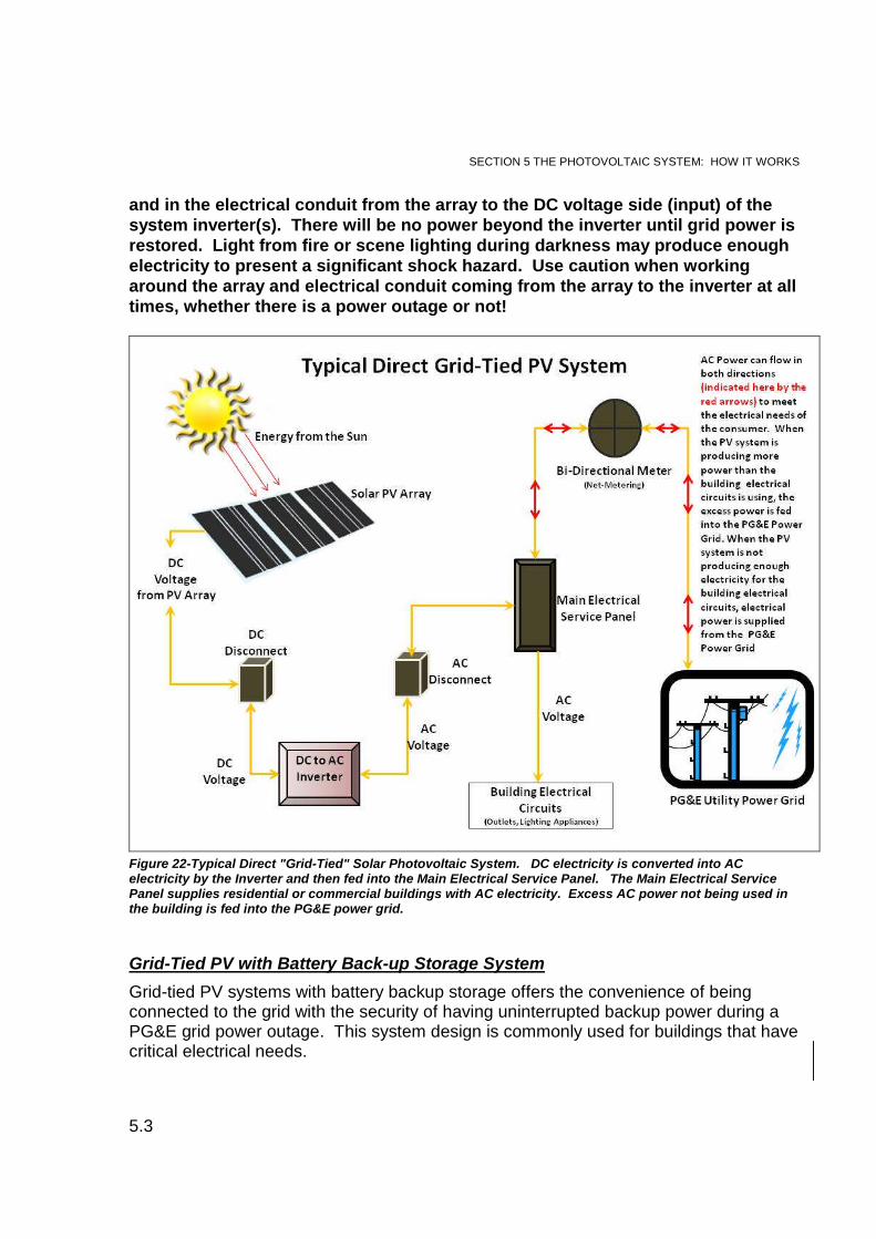
and in the electrical conduit from the array to the DC voltage side (input) of thesystem inverter(s). There will be no power beyond the inverter until grid power isrestored. Light from fire or scene lighting during darkness may produce enoughelectricity to present a significant shock hazard. Use caution when workingaround the array and electrical conduit coming from the array to the inverter at alltimes, whether there is a power outage or not!
Figure 22-Typical Direct "Grid-Tied" Solar Photovoltaic System. DC electricity is converted into ACelectricity by the Inverter and then fed into the Main Electrical Service Panel. The Main Electrical ServicePanel supplies residential or commercial buildings with AC electricity. Excess AC power not being used inthe building is fed into the PG&E power grid.
Grid-Tied PV with Battery Back-up Storage System
Grid-tied PV systems with battery backup storage offers the convenience of beingconnected to the grid with the security of having uninterrupted backup power during aPG&E grid power outage. This system design is commonly used for buildings that havecritical electrical needs.
SECTION 5 THE PHOTOVOLTAIC SYSTEM: HOW IT WORKS
5.4
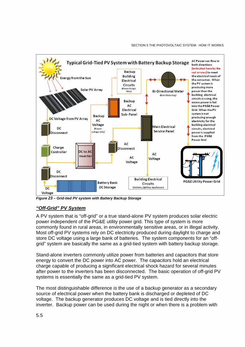
Grid-tied PV systems with battery back-up storage operate in the same basic manneras direct grid-tied PV systems and utilize Net Metering. The distinguishable differencebetween a direct grid-tied design and a battery backup storage design is that the batterybackup system incorporates a bank of batteries to store DC electricity for use duringpower outages. The DC electrical storage is accomplished by adding components intothe PV system designed to use excess DC electricity to charge the battery bank.
Safety precautions for working around an energized PV system must be followed.Identification of battery back-up storage systems must be reported immediately to IC toprevent accidental electrical shock. In order to isolate a battery back-up system,Firefighters should be familiar with the basic functions of the additional components,which include the following:
Charge Controller - To prevent the batteries from overcharging.
Bank of batteries - To store accumulated DC voltage for use when there is apower outage or no electricity is being produced, such as at night.
Stand-Alone Inverter - Inverters of this type use both AC power, on adedicated circuit when the PG&E grid is operating, and DC power suppliedfrom the battery bank during a power outage, to convert DC electricity intoAC electricity. The inverter utilizes DC voltage from the batteries andcapacitors that store energy to operate during an outage. Energy in thecapacitors will discharge soon after the power to the inverters has beenisolated. A significant electrical shock hazard could exist at all times.
Backup Electrical Sub-Panel and Electrical Circuits – During a power outagethe AC voltage being converted by the stand alone inverter is fed into abackup AC electrical circuit that energizes and feeds into a backup sub-panelbefore distributing power from the backup sub-panel into the buildingelectrical circuits. The sub-panel is a safety feature designed to isolateelectrical power during a power outage and any potential for electricitybackfeeding into the PG&E grid. Backup electrical circuits are tied into thenormal electrical circuits for the building such as outlets, lighting, andappliance circuits.
SECTION 5 THE PHOTOVOLTAIC SYSTEM: HOW IT WORKS
5.5
Figure 23 – Grid-tied PV system with Battery Backup Storage
“Off-Grid” PV System
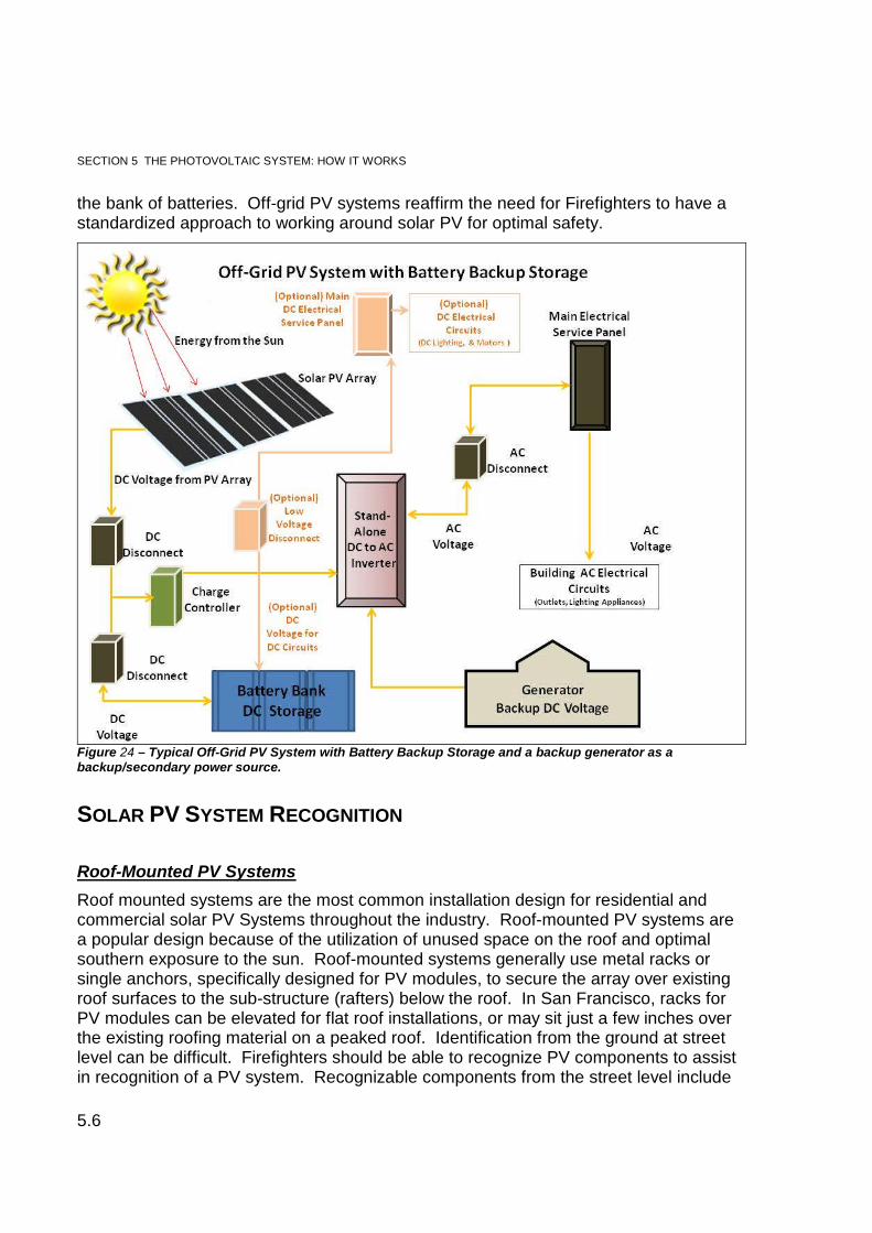
A PV system that is “off-grid” or a true stand-alone PV system produces solar electricpower independent of the PG&E utility power grid. This type of system is morecommonly found in rural areas, in environmentally sensitive areas, or in illegal activity.Most off-grid PV systems rely on DC electricity produced during daylight to charge andstore DC voltage using a large bank of batteries. The system components for an “off-grid” system are basically the same as a grid-tied system with battery backup storage.
Stand-alone inverters commonly utilize power from batteries and capacitors that storeenergy to convert the DC power into AC power. The capacitors hold an electricalcharge capable of producing a significant electrical shock hazard for several minutesafter power to the inverters has been disconnected. The basic operation of off-grid PVsystems is essentially the same as a grid-tied PV system.
The most distinguishable difference is the use of a backup generator as a secondarysource of electrical power when the battery bank is discharged or depleted of DCvoltage. The backup generator produces DC voltage and is tied directly into theinverter. Backup power can be used during the night or when there is a problem with
SECTION 5 THE PHOTOVOLTAIC SYSTEM: HOW IT WORKS
5.6
the bank of batteries. Off-grid PV systems reaffirm the need for Firefighters to have astandardized approach to working around solar PV for optimal safety.
Figure 24 – Typical Off-Grid PV System with Battery Backup Storage and a backup generator as abackup/secondary power source.
SOLAR PV SYSTEM RECOGNITION
Roof-Mounted PV Systems
Roof mounted systems are the most common installation design for residential andcommercial solar PV Systems throughout the industry. Roof-mounted PV systems area popular design because of the utilization of unused space on the roof and optimalsouthern exposure to the sun. Roof-mounted systems generally use metal racks orsingle anchors, specifically designed for PV modules, to secure the array over existingroof surfaces to the sub-structure (rafters) below the roof. In San Francisco, racks forPV modules can be elevated for flat roof installations, or may sit just a few inches overthe existing roofing material on a peaked roof. Identification from the ground at streetlevel can be difficult. Firefighters should be able to recognize PV components to assistin recognition of a PV system. Recognizable components from the street level include
SECTION 5 THE PHOTOVOLTAIC SYSTEM: HOW IT WORKS
5.7
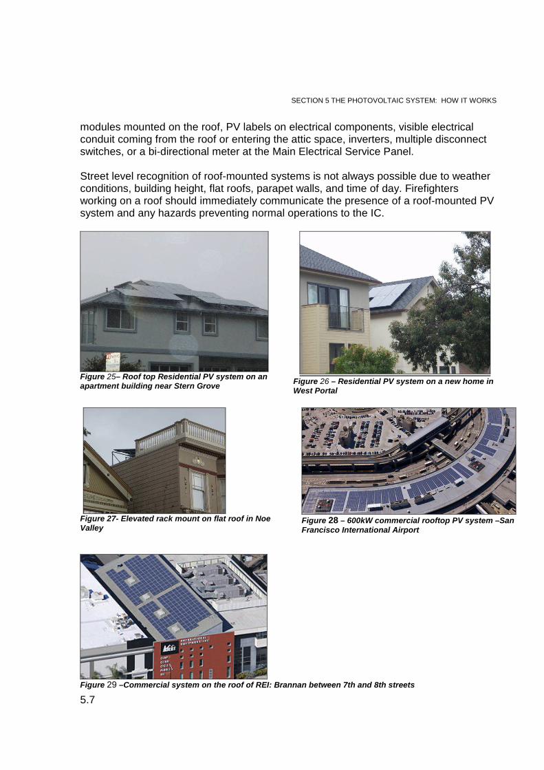
modules mounted on the roof, PV labels on electrical components, visible electricalconduit coming from the roof or entering the attic space, inverters, multiple disconnectswitches, or a bi-directional meter at the Main Electrical Service Panel.
Street level recognition of roof-mounted systems is not always possible due to weatherconditions, building height, flat roofs, parapet walls, and time of day. Firefightersworking on a roof should immediately communicate the presence of a roof-mounted PVsystem and any hazards preventing normal operations to the IC.
Figure 25– Roof top Residential PV system on anapartment building near Stern Grove
Figure 26 – Residential PV system on a new home inWest Portal
Figure 27- Elevated rack mount on flat roof in NoeValley
Figure 28 – 600kW commercial rooftop PV system –SanFrancisco International Airport
Figure 29 –Commercial system on the roof of REI: Brannan between 7th and 8th streets
SECTION 5 THE PHOTOVOLTAIC SYSTEM: HOW IT WORKS
5.8
Building-Integrated PV Systems
Solar electric technology is rapidly evolving; as the industry grows the technology andcomponents are being designed to be more efficient. These changes are occurring onboth residential and commercial PV systems. Building-integrated design of PVcomponents allows for better functionality, curb appeal and utilization of space, and foroptimal exposure to the sun.
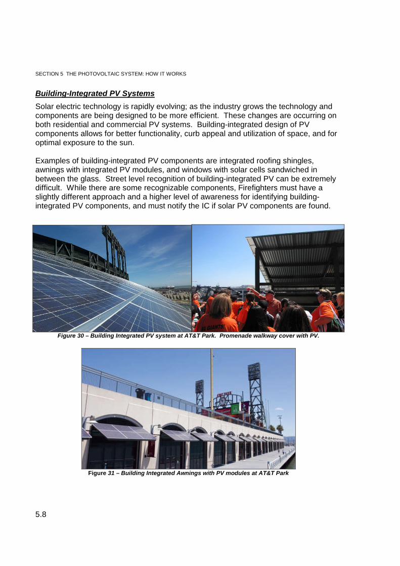
Examples of building-integrated PV components are integrated roofing shingles,awnings with integrated PV modules, and windows with solar cells sandwiched inbetween the glass. Street level recognition of building-integrated PV can be extremelydifficult. While there are some recognizable components, Firefighters must have aslightly different approach and a higher level of awareness for identifying building-integrated PV components, and must notify the IC if solar PV components are found.
Figure 31 – Building Integrated Awnings with PV modules at AT&T Park
Figure 30 – Building Integrated PV system at AT&T Park. Promenade walkway cover with PV.
SECTION 5 THE PHOTOVOLTAIC SYSTEM: HOW IT WORKS
5.9
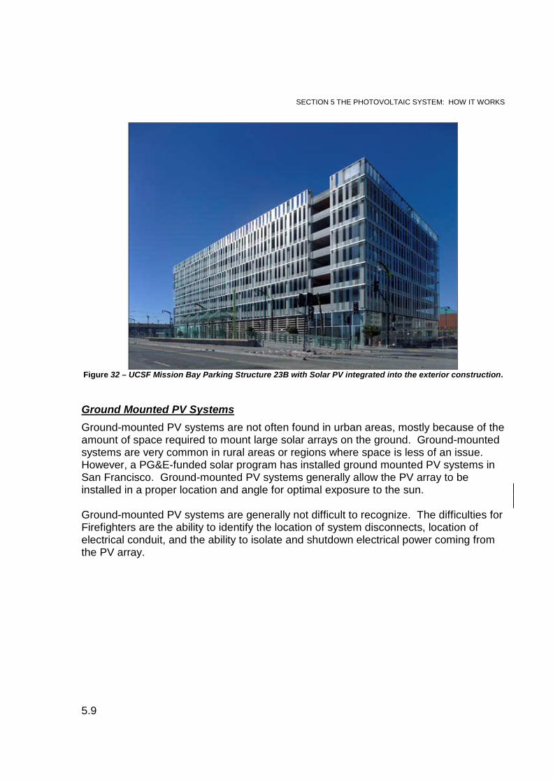
Figure 32 – UCSF Mission Bay Parking Structure 23B with Solar PV integrated into the exterior construction.
Ground Mounted PV Systems
Ground-mounted PV systems are not often found in urban areas, mostly because of theamount of space required to mount large solar arrays on the ground. Ground-mountedsystems are very common in rural areas or regions where space is less of an issue.However, a PG&E-funded solar program has installed ground mounted PV systems inSan Francisco. Ground-mounted PV systems generally allow the PV array to beinstalled in a proper location and angle for optimal exposure to the sun.
Ground-mounted PV systems are generally not difficult to recognize. The difficulties forFirefighters are the ability to identify the location of system disconnects, location ofelectrical conduit, and the ability to isolate and shutdown electrical power coming fromthe PV array.
SECTION 5 THE PHOTOVOLTAIC SYSTEM: HOW IT WORKS
5.10
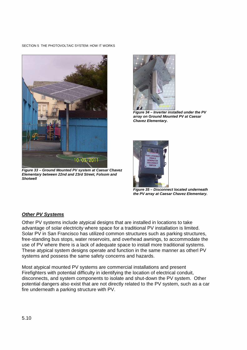
Figure 33 – Ground Mounted PV system at Caesar ChavezElementary between 22nd and 23rd Street, Folsom andShotwell
Figure 34 – Inverter installed under the PVarray on Ground Mounted PV at CaesarChavez Elementary.
Figure 35 – Disconnect located underneaththe PV array at Caesar Chavez Elementary.
Other PV Systems
Other PV systems include atypical designs that are installed in locations to takeadvantage of solar electricity where space for a traditional PV installation is limited.Solar PV in San Francisco has utilized common structures such as parking structures,free-standing bus stops, water reservoirs, and overhead awnings, to accommodate theuse of PV where there is a lack of adequate space to install more traditional systems.These atypical system designs operate and function in the same manner as otherl PVsystems and possess the same safety concerns and hazards.
Most atypical mounted PV systems are commercial installations and presentFirefighters with potential difficulty in identifying the location of electrical conduit,disconnects, and system components to isolate and shut-down the PV system. Otherpotential dangers also exist that are not directly related to the PV system, such as a carfire underneath a parking structure with PV.
SECTION 5 THE PHOTOVOLTAIC SYSTEM: HOW IT WORKS
5.11
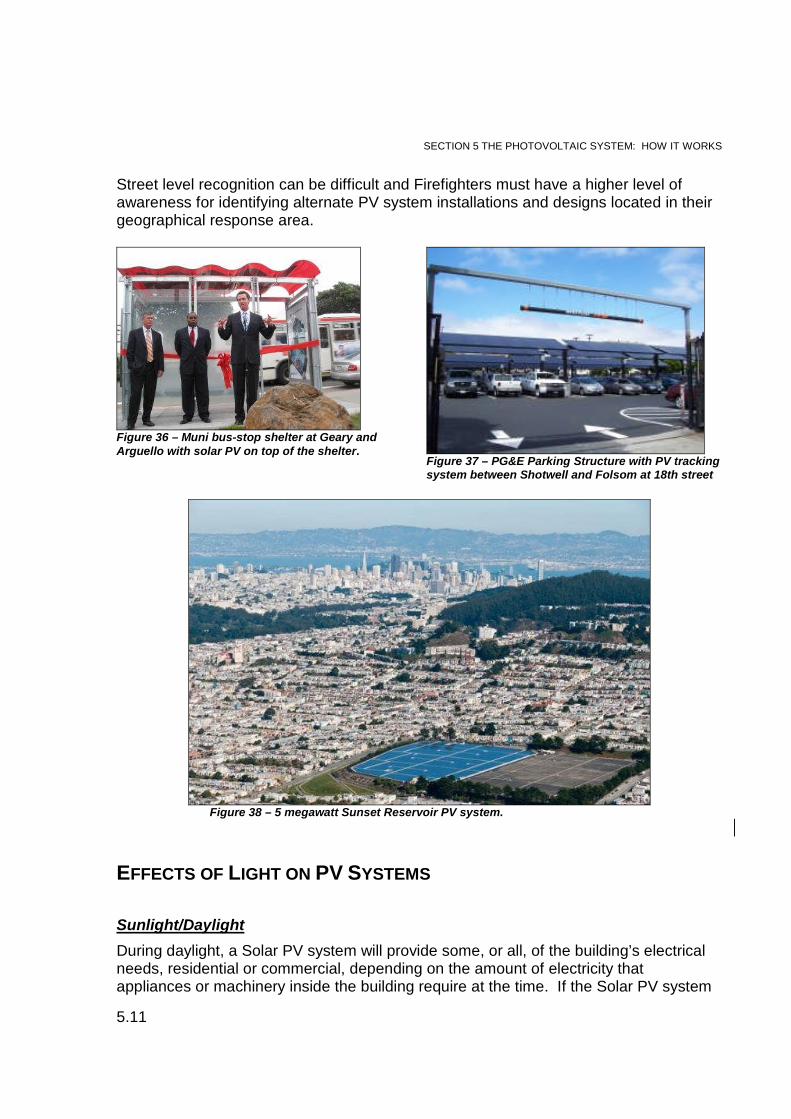
Street level recognition can be difficult and Firefighters must have a higher level ofawareness for identifying alternate PV system installations and designs located in theirgeographical response area.
Figure 36 – Muni bus-stop shelter at Geary andArguello with solar PV on top of the shelter.
Figure 37 – PG&E Parking Structure with PV trackingsystem between Shotwell and Folsom at 18th street
Figure 38 – 5 megawatt Sunset Reservoir PV system.
EFFECTS OF LIGHT ON PV SYSTEMS
Sunlight/Daylight
During daylight, a Solar PV system will provide some, or all, of the building’s electricalneeds, residential or commercial, depending on the amount of electricity thatappliances or machinery inside the building require at the time. If the Solar PV system
SECTION 5 THE PHOTOVOLTAIC SYSTEM: HOW IT WORKS
5.12
is not providing all the power needs, the balance of power needed is automaticallyprovided directly from the PG&E power grid. On days when sunlight is intense, the PVsystem will generally produce more power than needed. The excess power isautomatically fed into the PG&E power grid and a credit is recorded on the bi-directionalmeter (Net Metering).
During daytime hours, whether the sun is shining directly on the array or it is obscuredby overcast or other objects casting a shadow or creating shade, a PV system will stillgenerate DC power, at less than optimum levels. The intensity of sunlight or daylighton the solar array and the daily temperature will determine how much DC power isgenerated.
The PV system will produce less power on cloudy days and during winter months whensunlight is less intense due to clouds and overcast skies. The PV system will alsoproduce less power if the modules are obscured by dirt and/or shade. Dailytemperature affects optimum efficiency. Solar modules operate well during daylight;however, the modules are less efficient in higher temperatures. Moderate to mildtemperatures and/or cold weather assist with better conductivity of the PV system.
The amount of power being generated at any time during the day will still presenta significant electrical shock hazard that could result in permanent injury and/ordeath, regardless of the intensity of the light on the array. Firefighters shouldnever assume that low levels of daylight or less intense sunlight due to clouds orshade will stop a PV system from producing electricity.
Nighttime
Generally, under the absolute darkness of night, solar PV systems will not produceelectricity. However, low ambient lighting, artificial light from scene lighting, light fromfire, or street lighting may be able to generate enough light for solar cells to produce DCelectric power that could present an electrical shock hazard during hours of darkness.This has been documented by Underwriter Laboratories (UL) during recent experimentswith solar PV and the effects of light from sources other than the sun.
The potential to create solar electricity from light sources other than the sun dependson several conditions; intensity, location, and distance of the light source from the PVmodules.
In the recent past, the fire service considered a solar PV system safe to work around atnight or during darkness because it was assumped that the systems do not generateenough DC electricity to be harmful. However, the potential for a PV system togenerate enough DC electricity to present an electrical shock hazard, indicated by ULstudies, has prompted a change for overall Firefighter safety related to solar PV duringperiods of darkness at a working fire or an emergency scene.
SECTION 5 THE PHOTOVOLTAIC SYSTEM: HOW IT WORKS
5.13
Even though it is nearly impossible to know if the PV system is producing enough DCelectricity to present a hazard, Firefighters should consider the potential for electricalshock and take steps during hours of darkness to render the PV system as safe aspossible. Remember, during the night, a “grid-tied” PV system is not producing enoughDC power and electricity from the PG&E power grid is provided. Firefighters shouldalso be aware of the potential for “grid-tied” systems to have battery back-up.
**Safety Point: For overall safety, ALL PV systems should be isolated at any timeof day or night, before working around the system.

SECTION 6. PV SYSTEM HAZARDS AND FIREFIGHTER SAFETY
6.1
The general hazards that exist for solar PV on residential or commercial structures arenot strictly specific to PV technology. The same hazards exist with traditional electricalsystems. However, when the integrity of a PV system component or protective coveringis compromised or damaged due to fire or other destructive causes, the systempresents significant hazards and unique safety concerns for Firefighters at all times ofthe day or night.
Determining the presence of a solar PV system is the key to understanding andpreventing Firefighter injuries and/or Line of Duty Death (LODD).This section highlightshazards associated with overall Firefighter safety and PV technology.
ELECTRICAL SHOCK AND EFFECTS OF ELECTRICITY ON THE BODY
The primary danger for Firefighters working around any electrical system, includingsolar PV, is electrical shock. Electricity is dangerous because it is generally not seen orheard. Electricity can “grab” unsuspecting Firefighters without warning, which can leadto serious injury or death.
As discussed earlier, current flow (amperage) is what causes damage to humantissue. The amount of voltage (pressure) drives the current through the humanbody. Voltage is defined as the electrical potential of a circuit. It can be compared tothe PSI of water in a hose stream, or how much force or power is available to push thecurrent. Current (amperage) is a term used to describe the number of electrons movingpast a fixed point in one second. Current is simply the rate of flow of electrical current.Compared to a hose stream, electrical current (amperage) can be thought of as thenumber of gallons per minute flowing through the hose line. The amount of damageto human tissue caused by current flow (amperage) and voltage (pressure) is affectedby resistance. Resistance is a material’s opposition to the flow of current electrons.Resistance compared to a hose line is the amount of friction loss in the hose, valves,appliances, or nozzle. Resistance is measured in Ohms. With an understanding ofcurrent (amperage), voltage (pressure), and resistance on human tissue, Firefightersshould recognize the serious potential for electrical shock related to exposure toenergized PV components.
PV systems operate in a range between 120-600 volts DC. Typically, residential PVsystems operate in a range between 5-9 amps, while a large commercial PV systemcan operate with currents between 200-1200 amps. DC voltage from a PV system isconstant and current (amperage) levels pose a significant electrical shock hazard to anyFirefighter that makes contact with exposed wires or PV system components. The
SECTION 6. PV SYSTEM HAZARDS ANDFIREFIGHTER SAFETY
SECTION 6. PV SYSTEM HAZARDS AND FIREFIGHTER SAFETY
6.2
severity of injury and damage to human tissue from electrical shock is variable and isdetermined by the following factors:
The type of electrical current, alternating current (AC) or direct current (DC),flowing through the body. With both AC and DC there must be a completedpath or circuit for current to flow. Injury from electricity can occur if a person’sbody becomes part of a circuit by completing a path for current to flow.
The amount of current flow (amperage) through the body. Once resistance isovercome, amperage usually determines the degree of damage. At levels ofcurrent flow that exceed 1/10 of an amp (100 milliamps), the heart can stopbeating and start fibrillating.
The pathway of the current through the body. In order for electrical shock tooccur, there must be two points of contact on the body for current to enterand exit. This can be as simple as touching a DC or AC high-voltage wire orcomponent and being “electrically grounded” at the same time. Touching thehigh-voltage wire is one point of contact; being “electrically grounded” is thesecond point of contact, which completes the circuit and delivers theelectrical shock.
The duration of time the body is in contact with the current. As electricalcurrent flows through the body it breaks down electrical resistance allowingthe current to enter the underlying organs and structures. As current flows italso creates heat that will destroy and evaporate fluid in the tissue.
Resistance of the body. The question is how much voltage is dangerous?The answer depends on how much total resistance of the body is in thecircuit to oppose the flow of current. Voltage must be high enough toovercome the resistance before it can enter the body. The human body anddry PPE do provide some resistance to the flow of electricity. Conditions suchas being wet greatly reduce resistance, which allows current to flow moreeasily. Resistance of living tissue changes as the current flows. Skinrepresents an initial barrier to the flow of current and insulates the deepertissues, organs, and structures. Once an electrical current contacts skin, theamperage rises, followed by an abrupt and rapid climb. High voltageelectrical energy greatly reduces body resistance by quickly breaking downhuman skin. After the skin is punctured, the lowered resistance results inmassive current flow as electricity flows into the body. The change in currentflow occurs at the same time the electrical current punctures the skin. Oncethe skin resistance is gone, electrical current enters the underlying tissue.Internal tissue, except for bone, does not have good electrical resistance tocurrent flow. Electrical current will stop flowing when the heat from thecurrent produces tissue charring and evaporates tissue fluid. Electricalresistance is different for all people and depends on body size and shape,
SECTION 6. PV SYSTEM HAZARDS AND FIREFIGHTER SAFETY
6.3
area of body in contact with electrical source, how hard the body part ispressing against the electrical source at the point of contact, how moist thebody part is at the time of contact with the electrical source, and the type ofskin (callused or soft) at the point of contact with the electrical source.
Amount of voltage (pressure). The amount of voltage (pressure) drives thecurrent through the human body. High-voltage quickly reduces bodyresistance because of the amount of “pressure” and allows the current(amperage) to flow more easily.
Clothing and Jewelry. Rings, watchbands, necklaces, bracelets, and metalbutton, or rivets on clothing provide excellent electrical contact with yourbody, and can conduct electrical current.
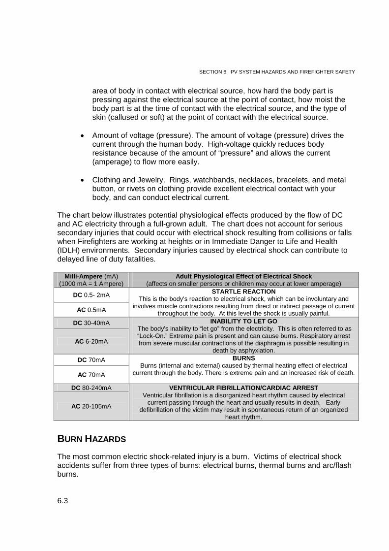
The chart below illustrates potential physiological effects produced by the flow of DCand AC electricity through a full-grown adult. The chart does not account for serioussecondary injuries that could occur with electrical shock resulting from collisions or fallswhen Firefighters are working at heights or in Immediate Danger to Life and Health(IDLH) environments. Secondary injuries caused by electrical shock can contribute todelayed line of duty fatalities.
Milli-Ampere (mA)(1000 mA = 1 Ampere)
Adult Physiological Effect of Electrical Shock(affects on smaller persons or children may occur at lower amperage)
DC 0.5- 2mASTARTLE REACTION
This is the body’s reaction to electrical shock, which can be involuntary andinvolves muscle contractions resulting from direct or indirect passage of current
throughout the body. At this level the shock is usually painful.AC 0.5mA
DC 30-40mA INABILITY TO LET GOThe body’s inability to “let go” from the electricity. This is often referred to as“Lock-On.” Extreme pain is present and can cause burns. Respiratory arrestfrom severe muscular contractions of the diaphragm is possible resulting in
death by asphyxiation.
AC 6-20mA
DC 70mA BURNSBurns (internal and external) caused by thermal heating effect of electrical
current through the body. There is extreme pain and an increased risk of death.AC 70mA
DC 80-240mA VENTRICULAR FIBRILLATION/CARDIAC ARRESTVentricular fibrillation is a disorganized heart rhythm caused by electrical
current passing through the heart and usually results in death. Earlydefibrillation of the victim may result in spontaneous return of an organized
heart rhythm.
AC 20-105mA
BURN HAZARDS
The most common electric shock-related injury is a burn. Victims of electrical shockaccidents suffer from three types of burns: electrical burns, thermal burns and arc/flashburns.
SECTION 6. PV SYSTEM HAZARDS AND FIREFIGHTER SAFETY
6.4
Electrical burns occur from electrical current flowing through tissue and bones. Aprimary sign of electrical burns is the presences of an entry and exit wound. Damagefrom electrical burns can be external and internal.
Thermal burns are generally considered to be contact burns when electrical shockvictims come in contact with hot surfaces of overheated electric conductors, electricconduit, or any other energized electrical equipment.
Electrical arc is the most common cause of high-voltage electrical burn injuries,which can occur while attempting to de-energize an electrical system. Arc/Flashburns are the direct result of contact or near contact with a high-voltage electricalsource. PV systems are considered high-voltage electrical sources that operatebetween 120-600v DC. An arc can occur between the high-voltage power source and agrounded human body. The temperature of an electrical arc can be as high 4000°Cand can melt bone.
Arc burns occur where the arc strikes the victim. Flash burns are caused by the “head”of the electrical arc when victims are in close proximity to the arc. The hot flash from anelectrical arc generally passes over the surface of the skin and results in superficialpartial-thickness burns. Flash burns do not cause internal electrical injury.
Firefighters should never attempt to cut or remove any PV system components or wiresbecause of the potential for high-voltage electrical arcing. Firefighters should followLock-Out/Tag-Out procedures when shutting down the main power disconnects for aPV system, or any electrical system, to avoid someone accidentally re-energizing thesystem.
TRIP, SLIP, AND/OR FALL HAZARD
The California Department of Public Health has reported PV worker fatalities andserious injuries from tripping and/or slipping on PV components that have resulted infalls from roof-tops and through skylights. Fatal falls have been linked to accidentalcontact with high-voltage components, or tripping on wires, conduit, and mountingracks.
The most common residential or commercial PV installations are on roof-tops; workingaround roof-top PV systems can be very difficult. The PV system modules, mountingracks, conduit and wires pose a significant risk for accidental electrical shock, tripping,slipping and falling off of a roof. Factors for increased potential for electrical shock,tripping, slipping, and falling are highlighted below:
A peaked or flat roof-top access and egress can be hindered and may notallow for safe walking areas.
SECTION 6. PV SYSTEM HAZARDS AND FIREFIGHTER SAFETY
6.5
The surface of PV modules is normally slippery. When installed on a peakedroof or when the modules are wet, they become extremely slippery. DO NOTwalk on modules.
Accidental contact with high-voltage PV components could cause involuntarymuscle reaction and could result in a fall from the roof.
Firefighters should never attempt to place a ladder on PV modules. Neverattempt to walk on or remove PV modules or components for access orventilation.
Do not attempt to break the glass covering PV modules, as this could exposehigh-voltage internal components within the module and increase the risk ofelectrical shock.
Building-integrated PV roofing modules, such as tiles or shingles, aredesigned to look like traditional roofing materials and may not be immediatelyvisible or identify at night. DO NOT attempt to walk across the roof orventilate a roof with building-integrated PV modules.
PV mounting racks, electrical conduit, and wires are generally installedslightly above the roof system and roof line, and cross between rows ofmodules.
The mounting racks, electrical conduit, and wires are sometimes partiallyconcealed and are not always visible during the day. They become evenmore difficult to identify in the dark or in the presence of smoke.
INCREASED ROOF LOAD HAZARD
When residential and commercial buildings are constructed, they are built to complywith the building codes. Residential compliance is generally not as stringent ascommercial building construction. This is largely due to the differences in the buildingmaterials being used. Residential construction includes the use of building materialsthat meet code specifications for normal weight loads within a residential structure. Thematerials include dimensional lumber and manufactured light-weight trusses that meetspecifications for structural integrity under normal building conditions.
Residential buildings are constructed to accommodate the dead loads of the roofingsystems and walls with a margin for the occasional live loads that could exist undernormal conditions. Examples of live loads include people walking on the roof, collectionof water from rain on the roof, or a truck company working on a roof during a workingfire.
SECTION 6. PV SYSTEM HAZARDS AND FIREFIGHTER SAFETY
6.6
Residential construction does not generally account for optional or increased deadloads from the installation of PV systems. This is especially true with light-weightconstructed trusses. The structural integrity is engineered to carry the building’s designload only under normal conditions. The addition of a PV system on a building with light-weight roof construction is not part of the normal building design load and ncreases thedead load for the roofing system.
For commercial structures, building materials will include cement and steel beams andgirders that have been designed by structural engineers to meet specific weight loads.
In San Francisco, the total dead load weight of an array can be no more than eightpounds per square foot. Most systems weigh much less than the maximum dead loadper square foot weight limit. For instances, the weight of a PV system consisting of 30modules wired together and installed over a 420 square foot roof area would be around2.5 pounds per square foot.
Most PV systems will range between 2.5 to 3.5 pounds per square foot. Theassumption is that the design of the roofing system will be able to handle the increasedweight capacity. Roof systems are normally engineered to carry a dead load ofapproximately 10 pounds per square foot and most composition roofing weighs aboutfour pounds per square foot.
As a comparison, a truck company consisting of four firefighters weighing approximately250 pounds each with gear and tools, standing in a 10’X10’, 100 square foot area on aroof has a live load weight of around 10 pounds per square foot. Generally, the totalweight of a truck company standing on a roof ventilating a building is not an immediateconcern.
During, a working fire in a building with a PV system, there is a potential for the roofsystem to fail sooner, especially, light-weight construction, with active fire in the atticspace. Increased dead load hazards, such as a PV system, could result in the roofbeing compromised to the point of imminent failure with direct flame impingement in theattic space. Increase the weight load further with the live load of a truck companyattempting to vertically ventilate and the result could be serious injury and or death forFirefighters.
Additionally, it is not uncommon to find multiple roofing layers on an older building.Having more than one or two layers of roofing can dramatically change the integrity ofthe roof system under fire conditions.
Firefighters need to be vigilant when assessing a building with a PV system to identify aweak or compromised roof system. The presence of a PV system on the roof and thestatus of the integrity of the roof system should be immediately reported to the IC.Firefighters should maintain constant situational awareness for changing conditions.Considerations for implementing alternative firefighting tactics should be communicatedwith the IC.
SECTION 6. PV SYSTEM HAZARDS AND FIREFIGHTER SAFETY
6.7
HAZARDOUS MATERIALS INHALATION HAZARD
Hazardous materials used in the semi-conductor industry, such as silicon, boron,phosphorus, cadmium, tellurium, arsenic, and gallium, are used in the construction ofPV modules and components. In PV modules these materials are sealed between thetop layer of glass and the plastic backing of the module, and then are encased in analuminum frame.
When the PV system is operating under normal conditions, these chemicals do notconstitute a hazard. However, during a fire involving PV modules or components, orthe adjacent areas around the modules or components, the aluminum frame canbecome deformed or melt, exposing the hazardous chemicals to direct flame and/orsignificant heat.
The exposure to flame and heat will cause the materials to dissipate in the smokeplume, constituting an inhalation hazard to Firefighters without breathing apparatus, aswell as people standing near the fire building and in the path of the plume. Theinhalation hazard from these chemicals can be mitigated for Firefighters by ensuring theconstant use of breathing apparatus and all PPE during fire attack and overhauloperations. All chemicals listed above are considered toxic under fire conditions; somehave a significant increased cancer risk with exposure.
PV SYSTEM BATTERY HAZARD
The bank of batteries used to store electricity are generally arranged in a line and areconnected to each other with “jumper wires” to increase voltage or amperage. Thereare two types of batteries used as electrical storage for PV systems, lead acid andlithium ion. The most common type of battery used is lead acid.
Lead acid batteries contain sulfuric acid that can cause harmful and explosive fumes.During normal operation, the bank of batteries will emit both hydrogen and hydrogensulfide gas, which are highly flammable. Hydrogen is lighter than air. Hydrogen sulfideis slightly heavier than air. For this reason, any equipment capable of producing aspark or open flames is not allowed near the battery back-up storage area. The areamust be adequately ventilated to prevent a build up hydrogen and hydrogen sulfide.
Though lead acid batteries are more common, lithium ion batteries are more efficientand take up less space. Lithium ion batteries are more efficient than lead acid.However, they are hazardous. When lithium ion batteries are subjected to direct flame,high temperatures, or abuse, such as mechanical damage or overcharging, they mayvent flammable liquid electrolyte, in liquid and gas form, which can explosively igniteand produce dangerous sparks. When lithium ion batteries burn, they produce a flare-like effect and can easily ignite other batteries or combustible materials in closeproximity. Lithium ion batteries that are actively burning will produce irritating gases,such as hydrogen fluoride, that are corrosive and toxic. Firefighters that come in
SECTION 6. PV SYSTEM HAZARDS AND FIREFIGHTER SAFETY
6.8
contact with the electrolyte inside of lithium ion batteries can complain of skin, eye, andmucous membrane irritation.
Firefighters working around battery banks must utilize proper PPE, including breathingapparatus, during fire attack and overhaul operations, should use caution in the batterystorage area, and should continuously assess for the development of a hazardousmaterials situation.
Firefighters should be familiar with how to isolate the bank of batteries from the PVsystem, if needed. If the PV system is disconnected from the batteries, the bank ofbatteries themselves still has potential for electrical shock. Firefighter should neverattempt to cut into or attempt to damage the batteries under any circumstance. If thebatteries are punctured by a conductive object, such as halligan tool, the object maybecome energized. Firefighters working around or adjacent to the battery storageareas should only use flashlights and equipment approved for CLASS 1 atmospheres.
When Firefighters determine that a PV system is using a battery bank to storeelectricity, the IC should be notified about the hazard and the location of the batterieswithin the building.
SECTION 7. INCIDENT PRIORITIES AND TACTICAL CONSIDERATIONS
7.1
Fire and emergency incidents for residential and commercial buildings have a basic andstandardized approached. However, fire and/or emergency incidents involving solar PVsystems require special considerations. The special considerations are a result of theinherent and associated hazards of PV systems and are necessary to ensure Firefighterhealth and safety and to accomplish fire control in a safe and efficient manner. IncidentPriorities and Tactical Considerations for solar PV systems during fire and/oremergency operations are outlined below.
PRE-INCIDENT IDENTIFICATION
Visual observations and inspections at the company level are critical steps toidentification and pre-planning when dealing with PV systems.
Companies should be aware of and should note any buildings or structureswith PV systems in their first due areas when:
o Responding to and returning from calls.o During area familiarization.o During routine company inspections (R1).
When PV systems are encountered the officer should:o Enter a Premise Hazard into HRMS.o Make a note in the journal identifying the PV system and the location
of any components such as disconnects or Main Electrical ServicePanel.
o Advise oncoming personnel so the information can be passed on
COMMUNICATIONS
All findings during the initial and on-going size-up and any actions taken needto be communicated to the Incident Commander (IC).
Incident size-up and identification of PV system and componentso Questions to consider:
Is there a solar PV array visible from the street upon approachand/or arrival?
Is the system inverter(s) visible or evident anywhere on thebuilding?
Is there PV labeling identifying the presence of a PV system? Are there any DC or AC disconnects visible and/or accessible? Is there visible electrical conduit penetrating the attic space or
near the main panel?
SECTION 7. INCIDENT PRIORITIES ANDTACTICAL CONSIDERATIONS
SECTION 7. INCIDENT PRIORITIES AND TACTICAL CONSIDERATIONS
7.2
Where is the PV array located? Controlling/Securing utilities and the PV system
o Notify the IC when utilities have been secured and the PV system hasbeen isolated.
On-going size-up throughout the incidento If the PV system is not identified on initial size-up companies assigned
to the roof or fire attack need to communicate the presence of a PVsystem or PV components immediately if encountered.
o If the PV array or components will impact or delay ventilation or fireattack the IC must be notified.
o Notify the IC if another form of ventilation is indicated due to limited orno access for ventilation.
o Accountability of crews.
SECURING UTILITIES
Securing Utilities is the TOP PRIORITY for incidents involving a PV system tomaintain a safe work environment for Firefighters.
Objectiveo De-energize PG&E power coming into the building.o De-energize electrical circuits leading from the PV system.o Isolate the DC power for the PV system and confine the power to the
array. Specifically assign a company to secure building utilities and the PV
system. Locate Main Electrical Service Panel.
o Shut off Main Breaker inside the Main Electrical Service Panel. This will shut down the AC power at the Main Electrical Service
Panel and AC power going into the building. Shutting off the Main Breaker will also de-energize the AC
power used by the inverter to convert DC into AC power.o If in doubt which is the Main Breaker, shut-off all circuit breakers inside
the Main Electrical Service Panel. Use caution for large commercial and high rise buildings.
Electrical power might still be needed to power HVACsystems and elevators.
Consult with building engineers (if applicable) to isolatethe PV system ONLY!
Consider using Lock-out/Tag-out system to secure PV system. Locate and isolate the PV system and battery bank (if applicable).
o Locate PV Inverter(s) and disconnects. Shut disconnects into the “OFF” position.
o Locate PV system batteries (if applicable). Shut disconnects for battery bank into the “OFF” position.
SECTION 7. INCIDENT PRIORITIES AND TACTICAL CONSIDERATIONS
7.3
o Locate and shut off any and all visible disconnects or switches for thePV system. Near Bi-directional Electric Meter. Near the inverters. Switch-gear on the roof. Roof top disconnects.
Notify the IC when the utilities and PV system have been secured. REMINDER:
o During hours of daylight, the Solar PV modules are ENERGIZEDand are still generating DC electricity from the modules to the DCside of the inverter, even after the Main Electrical Service Panelhas been secured.
o At night scene lighting or other artificial light on the PV array canproduce DC electricity with the potential for electrical shock.
FIRE ATTACK CONSIDERATIONS
Coordination of fire attack and ventilationo Fire attack could be delayed or hindered due to difficulties with
completing ventilation.o Advancing hose lines could be delayed due to securing PV and
building utilities. Be aware of energized PV system components inside the building. Notify the IC if wires and conduit inside the building is located.
o Avoid contact with conduit or wires if possible. Attempt to avoid directing hose streams directly onto energized PV system
components. If possible and indicated, use Dry Chemical Extinguishers or CO2
Extinguishers around PV components. If water is used PG&E recommends Fog Nozzle at a 30 degree pattern at
100 psi minimum at the tip and at least 33 feet from the energized source. UL experiments indicate that using a solid stream, smooth bore nozzle at 50
psi at the tip and at least 20 feet from the energized source is consideredsafe up to 1000 volts. PV systems have a maximum allowable voltage of 600volts.
Difficulties with fire attack must be communicated to the IC.
VENTILATION CONSIDERATIONS
Early recognition of the PV modules and identification of difficulties withcompleting ventilation objective is key for Firefighter safety.
Identify safe access and egress to the roof if possible. PV modules/array on the roof may affect ground or aerial ladder placement.
SECTION 7. INCIDENT PRIORITIES AND TACTICAL CONSIDERATIONS
7.4
Consider using Breathing Apparatus while working on the roof due toinhalation hazards.
Do not cut through any conduit or wires to complete ventilation due to thepotential for electrical shock.
Do not break PV modules with an axe or attempt to remove PV modules toventilate due to electrical shock hazard.
On a flat roof, try to cut a ventilation hole according to Department SOP’s.o Avoid standing underneath the elevated rack mount for PV
installations on a flat roof. On a peaked roof, consider utilizing another area of the roof that is not
covered with PV modules and notify the IC. If a ventilation hole cannot be cut directly over the fire, identify an alternate
location and notify the IC that an alternate location for the ventilation hole hasbeen selected so fire attack crews inside the building are aware of a potentialchange in fire behavior. If the modules limit roof area, consider altering thedimensions of the ventilation hole. For example, instead of a 4x4 hole a 2x4or 2x8 hole can be cut given the limited access.
If vertical ventilation cannot be accomplished because the PV system doesnot provide firefighters with clearance, consider changing ventilation tacticsand notify the IC immediately.
If a PV module is involved in fire, it does not present a hazard to utilize ahose line to extinguish the fire as long as all recommendations for PPE,SCBA, and use of water streams are followed.
SALVAGE/OVERHAUL CONSIDERATIONS
Make certain that the building utilities have be de-energized before initiatingoverhaul.
o Priority is to confirm that the PV system is shut down (De-Energized)and the DC power coming from the PV array is isolated at the arrayand is not coming into the building to prevent accidental electricalshock.
BE AWARE of electrical conduit when “pulling ceilings or “opening up” wallsduring salvage/overhaul operations. Electrical conduit could beENERGIZED!
Use extreme caution when performing salvage/overhaul during daylighthours.
Visually assess the PV system for overall damage and obvious hazards, suchas broken modules, loose or hanging wires, and spot fires in or around thePV system.
Visually assess the type of roofing material to determine if the roofingmaterial is flammable and if any actions need to taken to prevent flare up orrekindle.
If possible, visually assess the integrity of the roof system for stability.
SECTION 7. INCIDENT PRIORITIES AND TACTICAL CONSIDERATIONS
7.5
Smaller PV systems with safe access and egress should be covered with anopaque tarp (a tarp that does not allow light through) to prevent the modulesfrom producing DC power.
o Consider using canvas salvage covers on small PV systems to preventsunlight striking the modules. This will secure the PV system andrender it safe during daylight, or low/artificial light conditions, andprevent accidental electrical shock.
During daylight hours, PV systems (residential or commercial) that are toolarge to cover with an opaque tarp should be left alone and all personnel onscene should be aware that a PV system is present has not been isolated orshut down and is not safe.
o Consider special calling PV technician to secure the systems to renderthe PV systems safe
DO NOT remove or otherwise dismantle PV modules during salvage andoverhaul.
DO NOT cut any electrical wires or conduit during salvage and overhaul. DO NOT break PV modules during salvage and overhaul. DO NOT attempt to shut down or disable inverters other than using the DC
and AC disconnects during overhaul.

SECTION 8. SOLAR PHOTOVOLTAIC TERMINOLOGY/DEFINITIONS
8.1
AC DisconnectThe AC disconnect is the AC power shutoff. The AC disconnect is located inlinebetween the inverter and the Main Electrical Distribution Panel for the building.
AC VoltageAC stands for “Alternating Current.” This means that the voltage is not constant andchanges polarity (reversing positive and negative) or direction over time. AC is the typeof electricity that is found in your home and delivered by PG&E. AC voltage in thehome is commonly 110 volts for most ordinary electronics. Larger appliances, such asa clothes dryer, are usually 220 volts.
ArrayA group of modules wired together in series to generate a greater amount of DCvoltage. Arrays can be mounted in various locations on a building or adjacent to abuilding. Arrays will vary total size.
Combiner BoxThe combiner box is used as a collection point for the many wires from the modulesthat are wired together (combined). The wires coming into the combiner box will vary innumber depending on the number of PV modules in the array. Wires leaving thecombiner box will generally be encased in electrical conduit on the way to the DCdisconnect before the inverter(s).
DC DisconnectThe DC disconnect is the DC power shutoff. The DC disconnect is located inlinebetween the solar arrays and the inverter
DC voltageDC stands for “Direct Current.” This means that the voltage or current maintainsconstant polarity or direction over time. DC is the kind of electricity made by a battery(with definite positive and negative terminals), or the kind of charge generated byrubbing certain types of materials against each other. DC electricity must be convertedto AC electricity in order to be used for household appliances and electrical circuits.
Dead LoadDead load refers to a constant load in a structure (such as a bridge, building, ormachine) that is due to the weight of the members, the supported structure, andpermanent attachments or accessories.
SECTION 8. SOLAR PHOTOVOLTAICTERMINOLOGY/DEFINITIONS
SECTION 8. SOLAR PHOTOVOLTAIC TERMINOLOGY/DEFINITIONS
8.2
Grid TiedA solar PV system that is capable of feeding electrical power into the PG&E utilitypower grid.
InverterThe inverter converts incoming solar DC voltage from the modules to AC voltage beforegoing to the building circuit breaker panel.
LineIn relation to a given switch or device, line refers to wires or voltage being "supplied" toit from "upstream" or from the direction of the Main Electrical Service Panel or powersource.
Live LoadThe term live load refers to the weight or forces applied to a structure, excluding actualconstruction materials, from a variety of sources that are not permanently secured to astructure. Snow, wind, water accumulation, people, and equipment are examples oflive loads. Live Loads are variable and are generally thought of as temporary, movable,or there for a short duration. When buildings are constructed, reasonable Live Loadsare factored into the construction and are based on allowable parameters within thebuilding code. These simple calculations do not account for structural compromise,such as charring from a fire or an added Load, dead or live, which was not factored intothe structural integrity of a building.
LoadIn relation to a given switch or device, load refers to wires (or terminals) that are"downstream" from or controlled by the switch or device. Another use of the term "load"is to refer to the energy "user(s)" along the circuit's path, such as a light or appliance.By providing resistance, these items limit current and, in the process, do useful thingswith that current.
ModuleA single aluminum-framed solar panel covered with tempered glass. Modules aresometimes referred to as panels.
Module Level ControlSolar PV components designed to improve overall PV system efficiency and safety.Increased safety is achieved by improving the ability to isolate a PV system to preventaccidental electrical shock.

SECTION 8. SOLAR PHOTOVOLTAIC TERMINOLOGY/DEFINITIONS
8.3
Net MeteringAgreement between the utility company and the PV system owner to “bank” excesspower produced by the PV system and to feed it into the utility power grid. The excesspower used by the utility company is offset when the PV system owner needs to usepower from the utility power grid when the PV system is not producing power.Off GridA PV system that is not connected to the utility power grid. This type of system isotherwise known as a “stand-alone” system.
Photovoltaic CellA semi-conductor device designed to convert solar energy, produce by the sun, into DCelectric power.
PVPV stands for Photovoltaic. Solar Photovoltaic Systems generate DC electricity fromsunlight (photons).
PVTSolar Photovoltaic and Thermal Systems generate DC electricity and solar thermalheating for water co-generated from sunlight.

SECTION 8. SOLAR PHOTOVOLTAIC TERMINOLOGY/DEFINITIONS
9.1
Backstrom, Robert and Dini, David A. “Firefighter Safety and Photovoltaic InstallationsResearch Project” Underwriters Laboratories Incorporated, Northbrook, IL. November29, 2011 http://www.UL.com/
Excerpt from North Carolina, OFSM, “Module II: Basic Electrical Concepts andHazards” “Personnel Protection Devices for Specific Applications, Electric PowerResearch Institute, Project” 6850-02, Final Report, October 1999, prepared byUnderwriters Laboratories Incorporated
CAL FIRE-Office of the State Fire Marshal, “Solar Photovoltaic Installation Guideline”April 22, 2008 and “Fire Operations for Photovoltaic Emergencies” November 2010,http://www.osfm.fire.ca.gov/training/pdf/Photovoltaics/
Paiss, Matt, Fire Captain San Jose Fire Department, video and seminar “PhotovoltaicSystems and Firefighter Safety”, 2009, 2010 contributor to California OFSM“Photovoltaic Guidelines” and “Fire Operations for Photovoltaic Emergencies”,Photovoltaic consultant 2011
San Francisco Department of Environment, “San Francisco Solar Map,”http://sf.solarmap.org/
Cooperation from San Francisco International Brotherhood of Electrical Workers Local6
Enphase Energy Company, “PV Systems and Fire Safety” http://www.enphase.com/ ,1-877-797-4743, 1420 N.Mcdowell Blvd, Petaluma, CA, 94954
Dini, David A, Research Engineer, Electrical Hazard Group, Corporate Research,Underwriters Laboratory incorporated, “ Leakage Current Research Document,”gathered references with excerpts from the following sources; “Electrical Shock,” aneducational presentation of Underwriters Laboratories Inc., prepared by WalterSkuggevig, 1991; “Personnel Protection Devices for Specific Applications, ElectricPower Research Institute, Project 6850-02, Final Report”, October 1999, prepared byUnderwriters Laboratories Inc.; IEC-60479-1, “Effects of Current on Human Beings andLivestock – Part 1: General aspects”, International Electrotechnical Commission, 4
th
ed., 2005-07; “Electric Current Through the Human Body”, Walter Skuggevig,Underwriters Laboratories Inc. (undated publication); “Standard for Safety for PortableSpray Hose Nozzles for Fire-Protection Service”, UL401. 4th ed. UnderwritersLaboratories Inc., 2004; “Fire Protection Handbook” 20th ed., Quincy, MA: National FireProtection Association, 2008; G.W.N. Fitzgerald, “Fire Fighting Near Live ElectricalApparatus,” Ontario Hydro Research News, April – June 1959, vol. 11, no. 2;
SECTION 9. MANUAL REFERENCES