solar power adsorption ice maker system · solar power adsorption ice maker system a.v.kanade1 2,...
TRANSCRIPT
International Research Journal of Engineering and Technology (IRJET) e-ISSN: 2395 -0056
Volume: 02 Issue: 03 | June-2015 www.irjet.net p-ISSN: 2395-0072
© 2015, IRJET.NET- All Rights Reserved Page 477
Solar Power Adsorption Ice Maker System
A.V.Kanade1 , A.V.Kulkarni2 , D.A.Deshmukh3
1 Student ME(Heat Power)Mechanical Engg. Department, S.Y.C.E.T. Aurangabad, Maharashtra ,India 2 Associate Professor, Mechanical Engg. Department, S.Y.C.E.T. Aurangabad, Maharashtra ,India 3 Asistant Professor Mechanical Engg. Department, S.Y.C.E.T. Aurangabad, Maharashtra ,India
---------------------------------------------------------------------***---------------------------------------------------------------------
Abstract - The major attraction of solid adsorption refrigeration technology for cold production is that it can be powered entirely or partly by low grade energy such as waste heat and solar energy. Thus, adsorption refrigeration is considered alternative to the conventional vapour compression refrigerator, especially in remote areas of the world without grid connected electricity. These research paper are classified into four main groups: adsorption system development, adsorbent bed innovation, adsorbent/adsorbate material development and application of adsorption cooling system. In this system activated carbon developed from coconut shell has excellent gas adsorption properties, and heat of adsorption of carbon dioxide is higher than many so called permanent gases such as nitrogen, oxygen etc. In these system replacement of compressor by adsorption bed with utilization of Activated carbon/Methanol adsorbent pair. The aim of this paper is not only cutting down the energy cost but also preserving our environment. In these system dose not use CFCs so that our Ozone layer is safe. Adsorption refrigeration based on condensation and evaporation with adsorption reaction.
Key Words: Adsorption refrigeration, adsorbent, adsorbate, Adsorption air-conditioner, Adsorption cooling ,Desorption, Solar energy.
1. INTRODUCTION The consumption of low grade energy by the units does not pose any problems of emission of greenhouse gases (hydrofluorocarbon, carbon dioxide, nitrous oxide, methane, perfluorocarbon and sulphur hexafluoride). Furthermore, solar powered refrigeration based on adsorption cycle is simple, quiet in operation and adaptable to small, medium or large systems. Thus, adsorption refrigeration is considered alternative to the conventional vapour compression refrigerator, especially in remote areas of the world without grid connected electricity[3]. Activated carbon /methanol, activated carbon/ammonia, zeolite/water and silica gel/water are the adsorbent /adsorbate pairs commonly used in practically realized adsorption refrigeration cycles.
Pressure Swing Adsorption (PSA) simply defines a cyclical process where the pressure is alternatively raised and lowered thereby forcing an adsorbent to adsorb a particular adsorbate at its porous surface during pressurization and to release the adsorbate during de-pressurization. The adsorption process is exothermic which becomes endothermic during desorption. In a PSA system, the adsorbent is regenerated by reducing the gas pressure[4]. The adsorption/desorption cycle is perfectly reversible and can be repeated for years without causing any degradation in the adsorbent. The adsorption/desorption cycle is perfectly reversible and can be repeated for years without causing any degradation in the adsorbent. The PSA system has already revolutionized the gas separation industries over the last decade, and also finding increasing use in refrigeration industries as adiabatic de-sorption for a gas can, which produces a low enough cold temperature for replacement of CFCs from any refrigeration systems[16].
1.1 Adsorption In simple words an “Adsorption is the process that occurs when a gas or liquid accumulates on the surface of solid”.The gas or liquid which is been accumulated is known as adsorbate. The solid substance on which adsorbate accumulates is known as adsorbent. Adsorption is the accumulation of atoms or molecules on the surface of a material. This process creates a film of the adsorbate (the molecules or atoms being accumulated) on the adsorbent's surface. It is different from absorption, in which a substance diffuses into a liquid or solid to form a solution. The term sorption encompasses both processes, while desorption is the reverse process. Adsorption constitutes a solid sorption process by which the binding forces between fluid molecules (adsorbate) and the solid medium (adsorbent) derive from an electrostatic origin or from dispersion-repulsion forces. It is an exothermic and reversible process as a result of the gas-liquid phase change without modification of the solid itself[2]. The liberated energy during the adsorption is called isosteric heat of adsorption and its intensity depends on the nature of the adsorbent/ adsorbate pair, the adsorbed mass and the latent heat

International Research Journal of Engineering and Technology (IRJET) e-ISSN: 2395 -0056
Volume: 02 Issue: 03 | June-2015 www.irjet.net p-ISSN: 2395-0072
© 2015, IRJET.NET- All Rights Reserved Page 478
The principle of the solid-adsorption ice maker is explained using a Clapeyron diagram (in P versus -1/T). Fig.1 shows the idealized process undergone by adsorptive pair in achieving the refrigeration effect (producing ice). The cycle begins at a point A where the adsorbent is at a low temperature TA and at low pressure Pe (evaporator pressure). During the daylight, AB represents the heating of adsorptive pair. The progressive heating of the adsorbent from B to D causes some adsorbate to be desorbed and its vapor to be condensed at the condenser pressure Pc. When the adsorbent reaches its maximum temperature TD, desorption ceases[1].
Fig-1: An ideal adsorption cooling cycle in the claperyon diagram. Then the liquid refrigerant is transferred into the evaporator. During night, the decrease in temperature from D to F induces the decrease in pressure from Pc to Pe. Then the adsorption and evaporation occur while the adsorbent is cooled from F to A. During this cooling period heat is withdrawn both to decrease the temperature of the adsorbent and to withdraw adsorption heat.
Analysis Of Adsorption Refrigeration Cycle From the Clapeyron diagram, the total energy gained by the system during the heating period QT will be the sum of the energy QAB used to raise the temperature of the A.C+ methanol from point A to B and the energy QBD used for progressive heating of the A.C to point D and desorption of methanol[6]. QT = QAB + QBD QAB = (MA:C CpA:C + Cpm MmA) (TB - TA) QBD = [MA:C CpA:C + Cpm { (MmA + MmD)/2 } ] (TD - TB) + ( MmA – MmD)H The gross heat released during the cooling period Qe1 will be the energy of vaporization of methanol.
Qe1 = (MmA – MmD)L But the net energy actually used to produce ice Qe will be Qe = Qe1 +Qe2 where Qe2 is the energy necessary for cooling the liquid adsorbate from the temperature at which it is condensed to the temperature at which it evaporates. Qe2 = (MmA – MmD) Cpm (Tc - Te) Qice1 is the energy required to cool water from TA to 0 ºC and to produce ice Qice1 = M* (L* + Cpwater(TA - 0)) where M* and L* are the mass and latent heat of fusion of ice and net cooling produced will be Qice = M* L* Nomenclature Cp specific heat, kJ/kgK H heat of desorption, kJ/kg L latent heat of evaporation of the methanol, kJ/kg M mass, kg Q energy, kJ T temperature, ºC Subscripts c condenser e evaporator m methanol st steel pieces T total
1.2 Solar powered adsorption ice-maker system Adsorption refrigeration system uses solid adsorbent beds to adsorb and desorb a refrigerant to obtain cooling effect. These solid adsorbent beds adsorb and desorb a refrigerant vapor in response to changes in the temperature of the adsorbent. Here adsorbent is an Activated carbon and the refrigerant used is methanol.
International Research Journal of Engineering and Technology (IRJET) e-ISSN: 2395 -0056
Volume: 02 Issue: 03 | June-2015 www.irjet.net p-ISSN: 2395-0072
© 2015, IRJET.NET- All Rights Reserved Page 479
The basic adsorption refrigeration system, commonly referred to as the adsorption heat pump loop, or an adsorption refrigeration circuit, it consists of four main components: a solid adsorbent bed, a condenser, and an evaporator ice-box. The solid adsorbent bed desorbs refrigerant when heated and adsorb refrigerant vapour when cooled. In this manner, the bed can be used as a thermal compressor to drive the refrigerant around the system to heat or cool a heat transfer fluid or to provide space heating or cooling. Thus in this system bed(of activated carbon) acts as compressor so as to drive refrigerant(methanol) similar to compressor .The refrigerant is desorbed from the bed as it is heated to drive the refrigerant out of the bed and the refrigerant vapor is conveyed to a condenser. In the condenser, the refrigerant vapor is cooled and condensed to liquid. The low pressure condensate passes to an evaporator where the low pressure condensate is heat exchanged with the process stream or space to be conditioned to vaporize the condensate[8]. When further heating no longer produces desorbed refrigerant from the adsorbent bed, the bed is isolated and allowed to return to the adsorption conditions. When the adsorption conditions are established in the bed, the refrigerant vapor from the evaporator is reintroduced to the bed to complete the cycle. For the circulation of methanol in the system the whole system should be vaccumised. Paragraph comes content here. Paragraph comes content here. Paragraph comes content here. Paragraph comes content here. Paragraph comes content here. Paragraph comes content here. Paragraph comes content here. Paragraph comes content here. Paragraph comes content here.
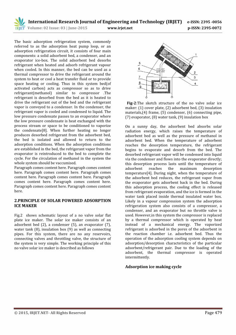
2.PRINCIPLE OF SOLAR POWERED ADSORPTION ICE MAKER Fig.2 shows schematic layout of a no valve solar flat plate ice maker. The solar ice maker consists of an adsorbent bed (2), a condenser (5), an evaporator (7), water tank (8), insulation box (9) as well as connecting pipes. For this system, there are no any reservoirs, connecting valves and throttling valve, the structure of the system is very simple. The working principle of this no valve solar ice maker is described as follows
Fig-2:The sketch structure of the no valve solar ice maker: (1) cover plate, (2) adsorbent bed, (3) insulation materials,(4) frame, (5) condenser, (6) connecting pipe, (7) evaporator, (8) water tank, (9) insulation box On a sunny day, the adsorbent bed absorbs solar radiation energy, which raises the temperature of adsorbent bed as well as the pressure of methanol in adsorbent bed. When the temperature of adsorbent reaches the desorption temperature, the refrigerant begins to evaporate and desorb from the bed. The desorbed refrigerant vapor will be condensed into liquid via the condenser and flows into the evaporator directly; this desorption process lasts until the temperature of adsorbent reaches the maximum desorption temperature[4]. During night, when the temperature of the adsorbent bed reduces, the refrigerant vapor from the evaporator gets adsorbent back in the bed. During this adsorption process, the cooling effect is released from refrigerant evaporation, and the ice is formed in the water tank placed inside thermal insulated water box. Likely in a vapour compression system the adsorption refrigeration system also consists of a compressor, a condenser, and an evaporator but no throttle valve is used. However,in this system the compressor is replaced by a thermal compressor which is operated by heat instead of a mechanical energy. The vaporized refrigerant is adsorbed in the pores of the adsorbent in the reaction chamber i.e. adsorbent bed. Thus the operation of the adsorption cooling system depends on adsorption/desorption characteristics of the particular adsorbent/refrigerant pair. Due to the loading of the adsorbent, the thermal compressor is operated intermittently.
Adsorption ice making cycle
International Research Journal of Engineering and Technology (IRJET) e-ISSN: 2395 -0056
Volume: 02 Issue: 03 | June-2015 www.irjet.net p-ISSN: 2395-0072
© 2015, IRJET.NET- All Rights Reserved Page 480
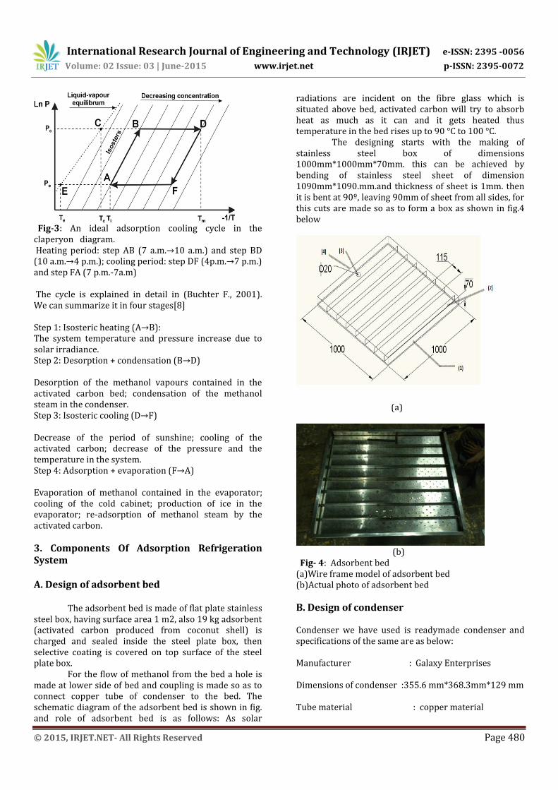
Fig-3: An ideal adsorption cooling cycle in the claperyon diagram. Heating period: step AB (7 a.m.→10 a.m.) and step BD (10 a.m.→4 p.m.); cooling period: step DF (4p.m.→7 p.m.) and step FA (7 p.m.-7a.m) The cycle is explained in detail in (Buchter F., 2001). We can summarize it in four stages[8] Step 1: Isosteric heating (A→B): The system temperature and pressure increase due to solar irradiance. Step 2: Desorption + condensation (B→D) Desorption of the methanol vapours contained in the activated carbon bed; condensation of the methanol steam in the condenser. Step 3: Isosteric cooling (D→F) Decrease of the period of sunshine; cooling of the activated carbon; decrease of the pressure and the temperature in the system. Step 4: Adsorption + evaporation (F→A) Evaporation of methanol contained in the evaporator; cooling of the cold cabinet; production of ice in the evaporator; re-adsorption of methanol steam by the activated carbon.
3. Components Of Adsorption Refrigeration System A. Design of adsorbent bed The adsorbent bed is made of flat plate stainless steel box, having surface area 1 m2, also 19 kg adsorbent (activated carbon produced from coconut shell) is charged and sealed inside the steel plate box, then selective coating is covered on top surface of the steel plate box.
For the flow of methanol from the bed a hole is made at lower side of bed and coupling is made so as to connect copper tube of condenser to the bed. The schematic diagram of the adsorbent bed is shown in fig. and role of adsorbent bed is as follows: As solar
radiations are incident on the fibre glass which is situated above bed, activated carbon will try to absorb heat as much as it can and it gets heated thus temperature in the bed rises up to 90 °C to 100 °C.
The designing starts with the making of stainless steel box of dimensions 1000mm*1000mm*70mm. this can be achieved by bending of stainless steel sheet of dimension 1090mm*1090.mm.and thickness of sheet is 1mm. then it is bent at 90º, leaving 90mm of sheet from all sides, for this cuts are made so as to form a box as shown in fig.4 below
(a)
(b) Fig- 4: Adsorbent bed (a)Wire frame model of adsorbent bed (b)Actual photo of adsorbent bed
B. Design of condenser Condenser we have used is readymade condenser and specifications of the same are as below: Manufacturer : Galaxy Enterprises Dimensions of condenser :355.6 mm*368.3mm*129 mm Tube material : copper material

International Research Journal of Engineering and Technology (IRJET) e-ISSN: 2395 -0056
Volume: 02 Issue: 03 | June-2015 www.irjet.net p-ISSN: 2395-0072
© 2015, IRJET.NET- All Rights Reserved Page 481
Tube diameter(in / out) : 15.87 mm Tube diameter( condenser) : 9.525 mm Total length of one tube : 5337.048mm Number of tubes used : 4 Fin material : Aluminum Total number of fins : 165
Fig- 5: Actual photo of Condenser
C. Design of evaporator The dimension of the evaporator is 300 mm * 300 mm * 100 mm. Evaporator is made up of stainless steel The evaporator is partly immersed in a water tank, which is made of stainless steel, and both the evaporator and water tank are placed in box covered with insulation. Role of evaporator is as follows: liquefied cooled methanol from condenser goes to evaporator and here it gives refrigerating effect to the water in the container as the evaporator is partially dipped in water container. In this way, it is very simple to remove the ice formed during adsorption cooling in the night. The lower portion of evaporator is made up of trapezoidal shape and dimensions are 0.03m * 0.04m. This increases surface area and ensures better heat transfer.
Fig-6: Wire frame model of evaporator
Fig -7: Actual trapezoidal portion of evaporator Fig- 8: Actual photo of evaporator D. Design of ice-box The diagram shown is the ice-box along with water container and an evaporator. Where, 1) Stainless steel tube of evaporator 2) Ice-box of wood 3) Water in container 4) Evaporator 5) Water container Ice box of system is made so as to insulate the water container. It is made up of wood. Dimension of ice-box made is 406mm*355mm*508m, it is situated in lower-most position. It is provided with handle and hinges on one side just as door of a box, so as to open the box and remove the container from the box when ice is formed. It is provided with hole on upper side of box from where copper tube of evaporator passes. Actual ice box of icemaker is as shown in figure below.
International Research Journal of Engineering and Technology (IRJET) e-ISSN: 2395 -0056
Volume: 02 Issue: 03 | June-2015 www.irjet.net p-ISSN: 2395-0072
© 2015, IRJET.NET- All Rights Reserved Page 482
Fig- 9: Icebox with evaporator and water container
3.1 EXPERIMENTAL SET UP Steps while integrating the system components: Adsorbent bed is filled with activated carbon( which is heated first in furnace) and making sure that the granules of carbon does not pass through sieve of stainless steel net and then covered by acrylic sheet by means of bolting it to the bed. Adsorbent bed is then insulated with Teflon, and cello tape. Distance between bed and acrylic sheet is then blocked by means of sealant and rubber of tyre so as to make the bed leak proof. Because of the sealing and insulation of adsorbent bed it is impossible for vaporized methanol to leak to atmosphere Skeleton
for the system is made by means of angles and nuts and bolts, it is as shown below. After the skeleton is made, adsorbent bed is then kept on it.
Now condenser is kept on middle angles and tube of condenser is then connected to the coupling of bed as explained in DESIGN OF BED. To ensure proper fixing of copper tube of condenser to the coupling, Teflon is used. Condenser is then fixed to angles by means of nuts and bolts by drilling holes on angles at specific location.
For the flow of liquid methanol from condenser to the evaporator extra copper pipe is used which is of same diameter as that of condenser. This pipe is then bent by bending machine at specific locations so as to ensure the connection of this pipe with the evaporator tube. (Proper care is taken while bending so that the tube will not get pinched.) This tube is insulated with hetlon so that the cooled methanol should not gain heat from surrounding.
Evaporator is filled with methanol (proper care is taken while filling methanol as it is harmful for eyes. filling of methanol is as shown below) and the tube of evaporator is then closed by cello tape until it is connected to the pipe, as methanol sublimes at atmospheric temp.
Evaporation of methanol occurs at 66 ºC-70 ºC and 25 ºC.
Ice-box made up of wood is then kept on lower angles. And evaporator is then inserted in the box now the closing (cello tape) is removed and the pipe of evaporator is then fixed to the bent copper tube and it is sealed by means of hetlon. Water container is inserted. And rubber pads are pasted onto the container on which evaporator rests (the pads are so pasted that the evaporator is partly immersed into water) so that the weight of the system is transferred to the floor through ice-box.
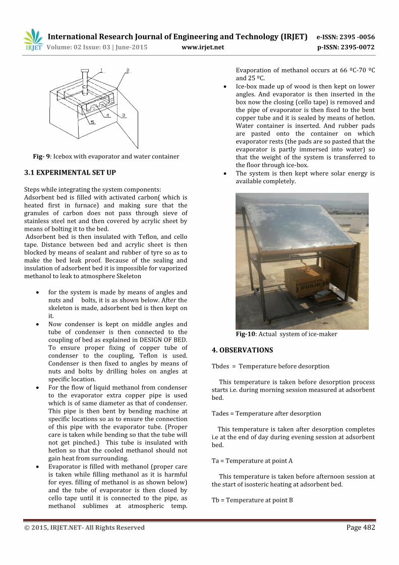
The system is then kept where solar energy is available completely.
Fig-10: Actual system of ice-maker
4. OBSERVATIONS Tbdes = Temperature before desorption This temperature is taken before desorption process starts i.e. during morning session measured at adsorbent bed. Tades = Temperature after desorption This temperature is taken after desorption completes i.e at the end of day during evening session at adsorbent bed. Ta = Temperature at point A This temperature is taken before afternoon session at the start of isosteric heating at adsorbent bed. Tb = Temperature at point B

International Research Journal of Engineering and Technology (IRJET) e-ISSN: 2395 -0056
Volume: 02 Issue: 03 | June-2015 www.irjet.net p-ISSN: 2395-0072
© 2015, IRJET.NET- All Rights Reserved Page 483
This temperature is taken at afternoon time of the day and at the end of isosteric heating and start of desorption process at adsorbent bed. Td = Temperature at point D This temperature is taken during evening session after desorption completes at adsorbent bed. Tcc = Temperature of condensate This is temperature of condensate measured by measuring water/ice temperature at ice box during early morning session. Tee = Temperature of evaporate This is temperature of evaporate measured by measuring water/ice temperature at ice box during early morning session.
4.1 OBSERVATION TABLE Table-1: Various Temp. of the solid adsorption solar powered ice-maker
Dates 1st 2nd 3rd 4th
18/04/15 20/04/15 30/04/15 02/05/15 Temperatures
(K)
Tbdes 30+273 29+273 31+273 30+273
Tades 50+273 50+273 48+273 49+273
Ta 30+273 29+273 31+273 30+273
Tb 38+273 37+273 39+273 38+273
Td 50+273 50+273 48+273 49+273
Tcc
15+273
16+273
15+273
15+273
Tee
14+273
15+273
14+273
14+273
Dates 5th 6th
04/05/15 08/05/15
Temperatures(K)
Tbdes 30+273 31+273
Tades 51+273 51+273
Ta 30+273 31+273
Tb 39+273 40+273
Td 51+273 51+273
Tcc
18+273
19+273
Tee
17+273
17+273
4.2 Variation Of Temperature Of Adsorbent Bed With Time The graph shown below is expected behavior of adsorbent bed. It is variation of temperature in the adsorbent bed because of incident solar radiations. Graph- 1: Variation of temperature of adsorbent bed with time Temperature in bed is directly proportional to the incident solar radiation. Effective solar radiations are available during period of 10 am to 3pm thus the temperature in bed during this period reaches to 100 ºC to 120 ºC. After 3 pm the temperature in bed gets lower and lower. Till 5.30 pm the temperature lowers to 20dgree c and desorption continues till that time. After this, temperature remains almost constant till 10.30 pm, now the adsorption of methanol starts. As adsorbent bed adsorbs vapours of methanol thus the temperature of adsorbent bed increases up to 60 ºC, approximately at midnight temperature is about 60 ºC – 70 ºC. after this the temperature again starts decreasing and exothermic reaction carry on. And now the bed will attain temperature of surrounding i.e. 25 °C 4.3. Some Conclusions Made From Observations
The graph shows that during desorption process the temperature of water is 20 ºC, it remains constant till the de-sorption process ends. Desorption process has
International Research Journal of Engineering and Technology (IRJET) e-ISSN: 2395 -0056
Volume: 02 Issue: 03 | June-2015 www.irjet.net p-ISSN: 2395-0072
© 2015, IRJET.NET- All Rights Reserved Page 484
duration of about 7-8 hours. It ends approximately at 7 pm.
As the desorption ceases the adsorption process will start. After a particular timing the temperature of water decreases rapidly, that timing is critical timing of approximately about 11.30p.m. During this process methanol absorbs heat of water and thus methanol will evaporate and evaporated methanol will be adsorbed by AC. Thus ice is formed. And temperature of this ice will be -5 ºC at about 3.30 am. After 3.30 am temperature of water increases slightly to 0 ºC. It remains constant till approximately 7am. Now the ice produced can be removed from the box.
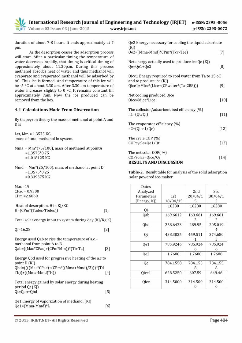
4.4 Calculations Made From Observation By Clapeyron theory the mass of methanol at point A and D is Let, Mm = 1.3575 KG, mass of total methanol in system. Mma = Mm*(75/100), mass of methanol at pointA =1.3575*0.75 =1.018125 KG Mmd = Mm*(25/100), mass of methanol at point D =1.3575*0.25 =0.339375 KG Mac =19 CPac = 0.9300 CPm =2.6060 Heat of desorption, H in KJ/KG H=(CPm*(Tades-Tbdes)) [1] Total solar energy input to system during day (KJ/Kg K) Qi=16.28 [2] Energy used Qab to rise the temperature of a.c.+ methanol from point A to B Qab=((Mac*CPac)+(CPm*Mm))*(Tb-Ta) [3] Energy Qbd used for progressive heating of the a.c to point D (KJ) Qbd=((((Mac*CPac)+(CPm*((Mma+Mmd)/2)))*(Td-Tb))+((Mma-Mmd)*H)) [4] Total energy gained by solar energy during heating period Qt (KJ) Qt=Qab+Qbd [5] Qe1 Energy of vaporization of methanol (KJ) Qe1=(Mma-Mmd)*L [6]
Qe2 Energy necessary for cooling the liquid adsorbate (KJ) Qe2=(Mma-Mmd)*CPm*(Tcc-Tee) [7] Net energy actually used to produce ice Qe (KJ) Qe=Qe1+Qe2 [8] Qice1 Energy required to cool water from Ta to 15 oC and to produce ice (KJ) Qice1=Mice*(Lice+(CPwater*(Ta-288))) [9] Net cooling produced Qice Qice=Mice*Lice [10] The collector/adsorbent bed efficiency (%) n1=(Qt/Qi) [11] The evaporator efficiency (%) n2=(Qice1/Qe) [12] The cycle COP (%) COPcycle=Qe1/Qt [13] The net solar COP( %) COPsolar=Qice/Qi [14]
RESULTS AND DISCUSSION Table-2: Result table for analysis of the solid adsorption solar powered ice-maker
Dates Analyzed
Parameters (Energy, KJ)
1st 18/04/15
2nd 20/04/1
5
3rd 30/04/1
5
Qi 16280 16280 16280
Qab 169.6612 169.6612
169.6612
Qbd 268.6423 289.95 205.0194
Qt 438.3035 459.5111
374.6805
Qe1 785.9246 785.9246
785.9246
Qe2 1.7688 1.7688 1.7688
Qe 784.1558 784.1558
784.1558
Qice1 628.5250 607.59 649.46
Qice 314.5000 314.5000
314.5000
International Research Journal of Engineering and Technology (IRJET) e-ISSN: 2395 -0056
Volume: 02 Issue: 03 | June-2015 www.irjet.net p-ISSN: 2395-0072
© 2015, IRJET.NET- All Rights Reserved Page 485
Dates Analyzed
Parameters (Energy, KJ)
4th 02/05/15
5th 04/05/15
6th 08/05/15
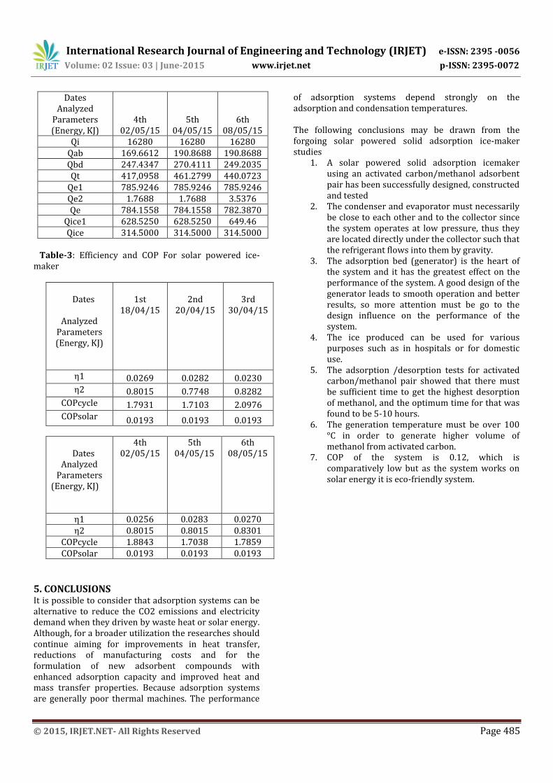
Qi 16280 16280 16280 Qab 169.6612 190.8688 190.8688 Qbd 247.4347 270.4111 249.2035 Qt 417,0958 461.2799 440.0723
Qe1 785.9246 785.9246 785.9246 Qe2 1.7688 1.7688 3.5376 Qe 784.1558 784.1558 782.3870
Qice1 628.5250 628.5250 649.46 Qice 314.5000 314.5000 314.5000
Table-3: Efficiency and COP For solar powered ice- maker
Dates
Analyzed
Parameters (Energy, KJ)
1st 18/04/15
2nd 20/04/15
3rd
30/04/15
η1 0.0269 0.0282 0.0230 η2 0.8015 0.7748 0.8282
COPcycle 1.7931 1.7103 2.0976 COPsolar 0.0193 0.0193 0.0193
Dates Analyzed
Parameters (Energy, KJ)
4th 02/05/15
5th 04/05/15
6th 08/05/15
η1 0.0256 0.0283 0.0270 η2 0.8015 0.8015 0.8301
COPcycle 1.8843 1.7038 1.7859 COPsolar 0.0193 0.0193 0.0193
5. CONCLUSIONS It is possible to consider that adsorption systems can be alternative to reduce the CO2 emissions and electricity demand when they driven by waste heat or solar energy. Although, for a broader utilization the researches should continue aiming for improvements in heat transfer, reductions of manufacturing costs and for the formulation of new adsorbent compounds with enhanced adsorption capacity and improved heat and mass transfer properties. Because adsorption systems are generally poor thermal machines. The performance
of adsorption systems depend strongly on the adsorption and condensation temperatures. The following conclusions may be drawn from the forgoing solar powered solid adsorption ice-maker studies
1. A solar powered solid adsorption icemaker using an activated carbon/methanol adsorbent pair has been successfully designed, constructed and tested
2. The condenser and evaporator must necessarily be close to each other and to the collector since the system operates at low pressure, thus they are located directly under the collector such that the refrigerant flows into them by gravity.
3. The adsorption bed (generator) is the heart of the system and it has the greatest effect on the performance of the system. A good design of the generator leads to smooth operation and better results, so more attention must be go to the design influence on the performance of the system.
4. The ice produced can be used for various purposes such as in hospitals or for domestic use.
5. The adsorption /desorption tests for activated carbon/methanol pair showed that there must be sufficient time to get the highest desorption of methanol, and the optimum time for that was found to be 5-10 hours.
6. The generation temperature must be over 100 °C in order to generate higher volume of methanol from activated carbon.
7. COP of the system is 0.12, which is comparatively low but as the system works on solar energy it is eco-friendly system.

International Research Journal of Engineering and Technology (IRJET) e-ISSN: 2395 -0056
Volume: 02 Issue: 03 | June-2015 www.irjet.net p-ISSN: 2395-0072
© 2015, IRJET.NET- All Rights Reserved Page 486
REFERENCES [1] R.Z. Wang, Y.X. Xu, J.Y. Wu and W. Wang;
Experiments on heat regenerative adsorption refrigerator and heat pump; International journal of energy research 22, 935-941 (1998).
[2] R. Z. Wang; Adsorption Refrigeration Research in Shanghai Jiao Tong University; Renewable and Sustainable Energy Reviews 5, 1-37 (2001).
[3] A.O. Dieng and R.Z. Wang; Literature review on solar adsorption technologies for ice making and air conditioning purposes and recent developments in solar technology; Renewable and sustainable energy reviews 5, 313-342 (2001).
[4] M. Li, R.Z. Wang; A study of the effects of collector and environment parameters on the performance of a solar powered solid adsorption refrigerator; Renewable Energy 27, 369–382 (2002).
[5] M. Li, R.Z. Wang; Heat and mass transfer in a flat plate solar solid adsorption; Renewable Energy 28, 613–622 (2003).
[6] L.W. Wang, R.Z. Wang, J.Y. Wu and K. Wang; Compound adsorbent for adsorption ice maker on fishing boats; International journal of refrigeration 27, 401-408 (2004).
[7] Zhaohui Qi; Study on hybrid system of solar powered water heater and adsorption ice maker; International journal of architectural science, Volume 6, No. 4, 168-172, 2005.
[8] Activated Carbon and Related Technology; Cameron Carbon Incorporated 2006.
[9] Li Yong and Ruzhu Z. Wang; Adsorption Refrigeration: A Survey of Novel Technologies; Recent Patents on Engineering 2007, 1, 1-21.
[10] G. Halder and S. C. Sarkar; The cooling effect by an adsorption- desorption refrigeration cycle; Journal of Energy in Southern Africa, Vol 18 No 2, May 2007.
[11] W. Chekirou, N. Boukheit and T. Kerbache; Numerical modeling of combined heat and mass transfer in a tubular adsorber of a solid adsorption solar refrigerator; Revue des Energies Renouvelables VOl. 10 Nº 3 (2007) 367-379.
[12] Kai Wang and Edward A. Vineyard; New opportunities for Solar Adsorption Refrigeration; a article in ASHRAE Journal, September 2011.
[13] Peerapong Thumautok, Wipawadee Wongsuwan and Tanongkiat Kiatsiriroat; Performance analysis of a solar adsorption heating and cooling systems; Chiang Mai University (CMU), Thailand, 50200.
[14] Piero M. Armenante; Adsorption; NJIT. [15] E E Anyanwu, N V Ogueke; Thermodynamic design
procedure for solid adsorption solar refrigerator, Int Journal of Renewable Energy, Elsevier, 30 (2005) pp 81-96
[16] M. Li and H.B. Huang; Experiental study on adsorbent of activated carbon with refrigerant of
ethanol for solar ice maker; Renewable energy 29 (2004) 2235-2244
BIOGRAPHIES
Mr.Avinash Vitthal Kanade [email protected] Student of ME(Heat Power) SYCET,Aurangabad, Maharashtra
Prof. Mr .Atul V.Kulkarni [email protected] Associate Professor, SYCET,Aurangabad, Maharashtra
Prof.Mr .Deepak A.Deshmukh [email protected] Asistant Professor, SYCET,Aurangabad Maharashtra
hoto
to