solar power generation using off grid … · of a solar photovoltaic system depends on various...
TRANSCRIPT

International Research Journal of Engineering and Technology (IRJET) e-ISSN: 2395 -0056
Volume: 03 Issue: 07 | July-2016 www.irjet.net p-ISSN: 2395-0072
© 2016, IRJET | Impact Factor value: 4.45 | ISO 9001:2008 Certified Journal | Page 2090
SOLAR POWER GENERATION USING OFF GRID SYSTEM
Priyanka Sharma 1, Vijay Kumar Garg2
1 Student Electrical Engineering Department, UIET, Kurukshetra, India,[email protected]
2 Professor, Electrical Engineering Department, UIET, Kurukshetra, India, [email protected]
--------------------------------------------------------------------***---------------------------------------------------------------------
Abstract - The demand of electrical energy is increasing day
by day and the same time sources of conventional energy are
decreasing. In order to across the gap between the increasing
demand and production some alternative energy resources
have to be utilized. A renewable energy resource appears to be
a bright solution. Solar energy is the best option because of its
natural availability, clean, environmental friendly and infinite
source of energy. The solar photo voltaic systems can be
classified in two types: off-grid and on-grid systems. The result
of a solar photovoltaic system depends on various factors such
as irradiation, temperature. To judge the value of the existing
system is very important for the characterization of the
existing problems and for its future scope. To calculate the
value of off grid photovoltaic system, model is prepared in a
MATLAB/SIMULINK. The main motive of this study is to
calculate the power and voltage levels, charging and
discharging trends of the battery bank.
Key Words: Matlab, Simulink, boost, off-grid systems,
photovoltaic, PMDC
1. INTRODUCTION
Renewable energy sources like solar, tidal and wind is
being exploited for the energy generation as they are
clean and natural source of energy. Solar energy field is
the best choice for Indian peninsula. The electricity
generation target was fixed as 1137.5 Billion Unit (BU)
for the year 2015-2016 i.e. growth increases 8.47%
over actual generation of 1048.673 for the previous
year (2014-2015). The required installation capacity
by 2030 would reach 772GW. [1]The PV cells permit
two type of installations either standalone or grid type
power plant. During 2015-16, Off Grid and
Decentralized Solar applications Program project
capacity of 191.158mw is calculated. The stand-alone
home systems would provide power for small houses
up to 1 kwh or through the installation of a power plant
in the village which would lighten up all the houses as
well as community centre and street lights. [2] India
has total solar PV installed capacity around 5547MW
till Feb. The solar PV system is depends upon many
factors like the irradiation and temperature. [4]But the
overall system efficiency is a function of the
performance of various components in the system such
as array, MPPT, converter, storage device. [3] Explains
how the atmospheric conditions affecting the output of
a system. Every system should study based on some
generalized parameters [3]. The development of a solar
photovoltaic system is explained in MATLAB.
Difference between a standalone and a grid connected
system is the energy storage. Standalone system stores
the surplus energy in the storage system like battery
while the grid connected system injects the energy
produced to the grid. [5-6]This paper is divided in to
two parts. The first part includes the modeling of
various components and the second part contains of
the simulation results.
2. DESCRIPTION OF SOLAR OFF GRID SYSTEM:
Fig: Electric generation from off grid system.
A. PV PANEL:
A PV module is constituted by arraying a group of
many tiny cells. A PV cell is a P-N junction formed from
a semiconductor material usually silicon or
germanium. When the cell is exposed to solar radiation
the electron hole pair is formed in the cell. Due to
internal electric field drift is sustained. If the terminals

International Research Journal of Engineering and Technology (IRJET) e-ISSN: 2395 -0056
Volume: 03 Issue: 07 | July-2016 www.irjet.net p-ISSN: 2395-0072
© 2016, IRJET | Impact Factor value: 4.45 | ISO 9001:2008 Certified Journal | Page 2091
of the cells are short circuited, current will flow in the
circuit. (Current through cell is known as short circuit
current) [7]. If the terminals of the cells are open
circuited current generated is shunted through a diode
connected in parallel with the cell (its terminal voltage
is known as open circuit voltage).
The simplest equivalent circuit of a solar cell is a
current source in anti-parallel with a diode as in
figure1. The output of the current source is directly
proportional to the light falling on the cell
(photocurrent Iph). [8]
Figure 1: Single diode model of a solar cell [9]
Applying Kirchhoff’s current law, we get [10]
Iph=I0+IRsh+I (1)
We get the following equation for the photovoltaic
current:
I= Iph-I*Rsh-Io (2)
I = Iph –Io* [(exp (V+I.Rs)/VT)-1]-[(V+I.Rs)/Rsh] (3)
Where, Iph is denoted as Isolation current, I is represent
the cell current, Io is the Reverse saturation current, V
is the voltage of cell, Rs is the resistance of series,[11]
VT is represents the Thermal voltage (KT/q), K is
denoted as Boltzmann constant, T is denoted as
Temperature in Kelvin, q is the Charge of an electron.
B. BOOST CONVERTER:
A step up converter or boost converter is a DC to DC
converter steps up voltage (while stepping down
current) from its supply to its load . It is a class of
switched-mode power supply (SMPS) containing diode
and transistor and at least one energy storage element
from a capacitor, inductor, or the two in combination.
To reduce voltage ripple, filters made of capacitors and
sometimes in combination with inductors are normally
added to such a converter's output (load-side filter)
and input (supply-side filter).[12]
Fig 2: Boost converter.
C. PERTURB AND OBSERVE METHOD
The “Perturb and Observe” is the algorithm of MPPT
which is used to modify the operating voltage or
current of the photovoltaic (PV) system until the
maximum power point is achieved. For example, if the
voltage is increasing on a panel then the output power
of a panel is also increasing, then the PV system
increases the operating voltage until the output power
starts to decrease. When this stage comes, then the
voltage is continuously decreasing up to the maximum
output power comes [19] and this process is continued
until the maximum power point is come. Thus, the
value of power output is approximately oscillates
around a maximum power point until it stabilizes.
Perturb and observe is the maximum used MPPT
method due to its ease or effective enforcement. The
major disadvantages of the perturb and observe
method is that in the steady state the operational
power oscillates around the maximum power point.
Also, this algorithm can track a wrong path, when the
changes in irradiance levels happening quickly. [20]
D. INCREMENTAL CONDUCTANCE MPPT
ALGORITHIM:
In this method Incremental conductance is the
operating point for a PV panel which synchronize with
its maximum power output can be expressed as
mathematically:
= -
International Research Journal of Engineering and Technology (IRJET) e-ISSN: 2395 -0056
Volume: 03 Issue: 07 | July-2016 www.irjet.net p-ISSN: 2395-0072
© 2016, IRJET | Impact Factor value: 4.45 | ISO 9001:2008 Certified Journal | Page 2092
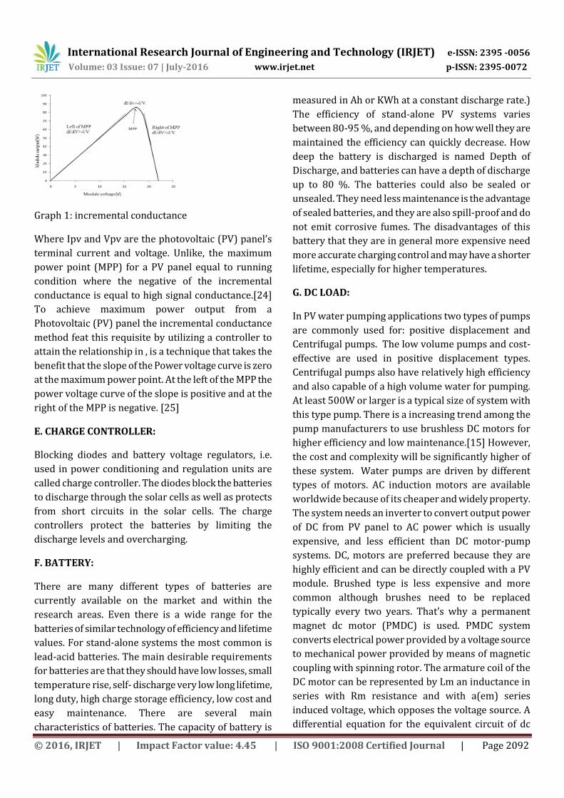
Graph 1: incremental conductance
Where Ipv and Vpv are the photovoltaic (PV) panel’s
terminal current and voltage. Unlike, the maximum
power point (MPP) for a PV panel equal to running
condition where the negative of the incremental
conductance is equal to high signal conductance.[24]
To achieve maximum power output from a
Photovoltaic (PV) panel the incremental conductance
method feat this requisite by utilizing a controller to
attain the relationship in , is a technique that takes the
benefit that the slope of the Power voltage curve is zero
at the maximum power point. At the left of the MPP the
power voltage curve of the slope is positive and at the
right of the MPP is negative. [25]
E. CHARGE CONTROLLER:
Blocking diodes and battery voltage regulators, i.e.
used in power conditioning and regulation units are
called charge controller. The diodes block the batteries
to discharge through the solar cells as well as protects
from short circuits in the solar cells. The charge
controllers protect the batteries by limiting the
discharge levels and overcharging.
F. BATTERY:
There are many different types of batteries are
currently available on the market and within the
research areas. Even there is a wide range for the
batteries of similar technology of efficiency and lifetime
values. For stand-alone systems the most common is
lead-acid batteries. The main desirable requirements
for batteries are that they should have low losses, small
temperature rise, self- discharge very low long lifetime,
long duty, high charge storage efficiency, low cost and
easy maintenance. There are several main
characteristics of batteries. The capacity of battery is
measured in Ah or KWh at a constant discharge rate.)
The efficiency of stand-alone PV systems varies
between 80-95 %, and depending on how well they are
maintained the efficiency can quickly decrease. How
deep the battery is discharged is named Depth of
Discharge, and batteries can have a depth of discharge
up to 80 %. The batteries could also be sealed or
unsealed. They need less maintenance is the advantage
of sealed batteries, and they are also spill-proof and do
not emit corrosive fumes. The disadvantages of this
battery that they are in general more expensive need
more accurate charging control and may have a shorter
lifetime, especially for higher temperatures.
G. DC LOAD:
In PV water pumping applications two types of pumps
are commonly used for: positive displacement and
Centrifugal pumps. The low volume pumps and cost-
effective are used in positive displacement types.
Centrifugal pumps also have relatively high efficiency
and also capable of a high volume water for pumping.
At least 500W or larger is a typical size of system with
this type pump. There is a increasing trend among the
pump manufacturers to use brushless DC motors for
higher efficiency and low maintenance.[15] However,
the cost and complexity will be significantly higher of
these system. Water pumps are driven by different
types of motors. AC induction motors are available
worldwide because of its cheaper and widely property.
The system needs an inverter to convert output power
of DC from PV panel to AC power which is usually
expensive, and less efficient than DC motor-pump
systems. DC, motors are preferred because they are
highly efficient and can be directly coupled with a PV
module. Brushed type is less expensive and more
common although brushes need to be replaced
typically every two years. That’s why a permanent
magnet dc motor (PMDC) is used. PMDC system
converts electrical power provided by a voltage source
to mechanical power provided by means of magnetic
coupling with spinning rotor. The armature coil of the
DC motor can be represented by Lm an inductance in
series with Rm resistance and with a(em) series
induced voltage, which opposes the voltage source. A
differential equation for the equivalent circuit of dc

International Research Journal of Engineering and Technology (IRJET) e-ISSN: 2395 -0056
Volume: 03 Issue: 07 | July-2016 www.irjet.net p-ISSN: 2395-0072
© 2016, IRJET | Impact Factor value: 4.45 | ISO 9001:2008 Certified Journal | Page 2093
motor can be derived by using Kirchhoff’s voltage law
around the electrical loop.[16]
Vm (k) = Rm Ia (k) + Lm d Ia (k) / dt + em (k) (4)
The water pump chosen here is submersible solar
pump for its size and cost.
III SIMULATION RESULTS:
A. MODELLING OF PV ARRAY WITH BOOST
CONVERTER USING MPPT
Fig: simulation of pv array using mppt.
The PV array consists of 40 strings in parallel and 700
series connected modules per string connected in
series .The boost converter connected with PV Array
and operated by MPPT controller after 0.1 s.
Specifications for PV Array are: Short circuit current:
Isc= 3.27 Open circuit voltage: Voc= 400 V. Voltage and
current at maximum power Vmp:= 395.8V,Imp=
2.78A.The initial voltage is obstinate at 250 V for the IC.
Fig: output with PWM
Fig: output with incremental mppt
Fig: output with p and o mppt
B. BATTERY WITH CHARGE CONTROLLER:
The battery capacity is measured in ampere-hours (Ah)
or kWh at a constant discharge rate. (If a battery
should be able to produce energy on one day i.e not
sunny it needs to have more capacity installed than
what the load requires during one day. This is called
autonomy). In which we have 4800/746= 6.4h
something time to discharge. The efficiency of stand-
alone PV systems varies between 80-95 %, and
depending on how good they are maintained the
efficiency can decrease. The charge controllers protect

International Research Journal of Engineering and Technology (IRJET) e-ISSN: 2395 -0056
Volume: 03 Issue: 07 | July-2016 www.irjet.net p-ISSN: 2395-0072
© 2016, IRJET | Impact Factor value: 4.45 | ISO 9001:2008 Certified Journal | Page 2094
the batteries by limiting the discharge levels and
overcharging. The main desirable requirements for
batteries are that they should have very few losses,
small temperature rise, self- discharge very low long
lifetime, long duty cycle (have long periods of low
charge), high charge storage efficiency, low cost and
easy maintenance.
Fig: Battery with charge controller
Result of charging current and charging voltage from
battery with the help of charge controller and pv panel.
Fig: discharge from battery voltage PWM
Fig: discharge from battery voltage incremental
Fig: discharge from battery voltage p and o
The array of PV modules produces DC and the amount
varies depending on the design. When several solar
cells are attached together the construction is called a
module. The modules can be constructed in several
ways in order to meet different demands within
electricity production at different voltages. The cells
can be connected in both parallel and series
connections but will produce DC.
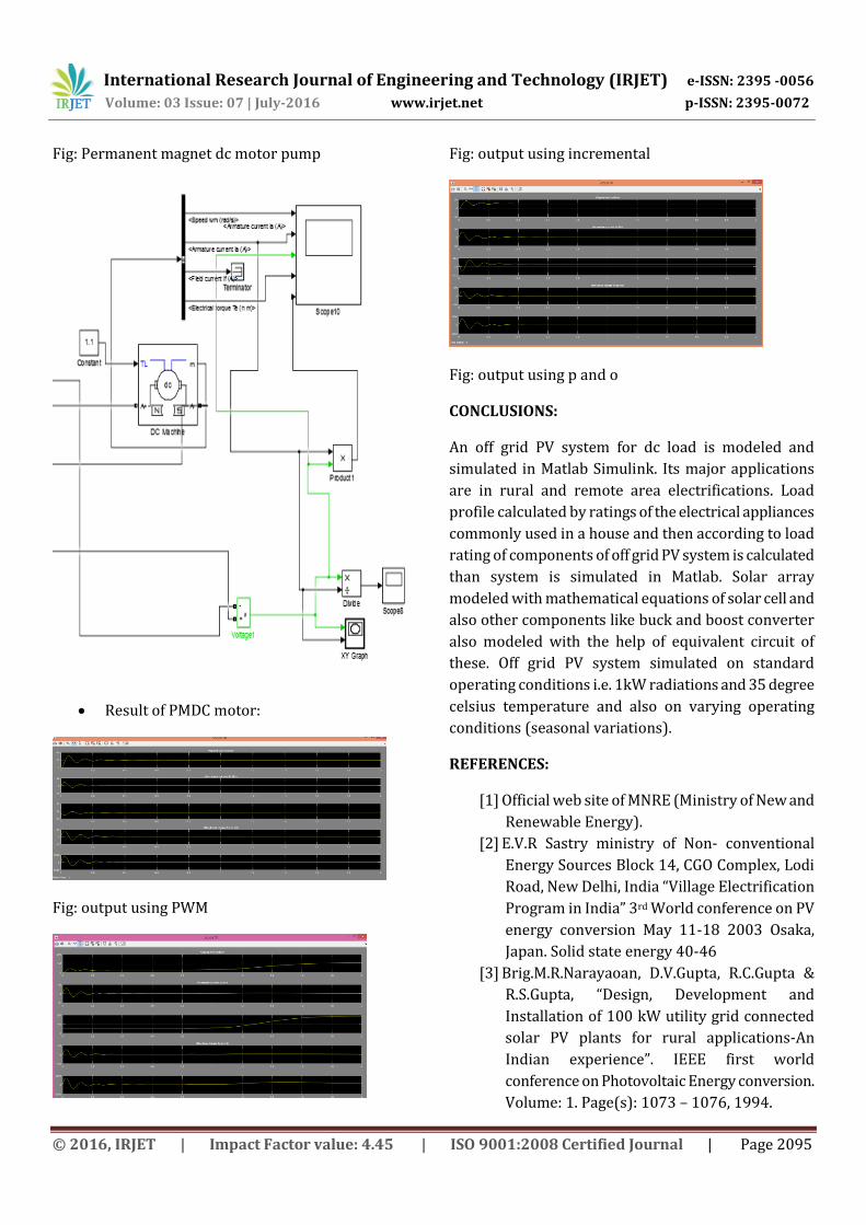
C. MODELLING OF PMDC MOTOR PUMP:
The water pump chosen here for its size and cost is
submersible solar pump. It is diaphragm-type positive
displacement pump equipped with a brushed
permanent magnet DC motor and designed for use in
standalone water delivery systems, specially for water
delivery in remote locations.
International Research Journal of Engineering and Technology (IRJET) e-ISSN: 2395 -0056
Volume: 03 Issue: 07 | July-2016 www.irjet.net p-ISSN: 2395-0072
© 2016, IRJET | Impact Factor value: 4.45 | ISO 9001:2008 Certified Journal | Page 2095
Fig: Permanent magnet dc motor pump
Result of PMDC motor:
Fig: output using PWM
Fig: output using incremental
Fig: output using p and o
CONCLUSIONS:
An off grid PV system for dc load is modeled and
simulated in Matlab Simulink. Its major applications
are in rural and remote area electrifications. Load
profile calculated by ratings of the electrical appliances
commonly used in a house and then according to load
rating of components of off grid PV system is calculated
than system is simulated in Matlab. Solar array
modeled with mathematical equations of solar cell and
also other components like buck and boost converter
also modeled with the help of equivalent circuit of
these. Off grid PV system simulated on standard
operating conditions i.e. 1kW radiations and 35 degree
celsius temperature and also on varying operating
conditions (seasonal variations).
REFERENCES:
[1] Official web site of MNRE (Ministry of New and
Renewable Energy).
[2] E.V.R Sastry ministry of Non- conventional
Energy Sources Block 14, CGO Complex, Lodi
Road, New Delhi, India “Village Electrification
Program in India” 3rd World conference on PV
energy conversion May 11-18 2003 Osaka,
Japan. Solid state energy 40-46
[3] Brig.M.R.Narayaoan, D.V.Gupta, R.C.Gupta &
R.S.Gupta, “Design, Development and
Installation of 100 kW utility grid connected
solar PV plants for rural applications-An
Indian experience”. IEEE first world
conference on Photovoltaic Energy conversion.
Volume: 1. Page(s): 1073 – 1076, 1994.

International Research Journal of Engineering and Technology (IRJET) e-ISSN: 2395 -0056
Volume: 03 Issue: 07 | July-2016 www.irjet.net p-ISSN: 2395-0072
© 2016, IRJET | Impact Factor value: 4.45 | ISO 9001:2008 Certified Journal | Page 2096
[4] Wind and Solar power system (Mukund R.
Patel)
[5] D. Picault, B. Raison, and S. Bacha, “Guidelines
for evaluating grid connected PV system
topologies”. IEEE International Conference on
Industrial Technology. Page(s):pp. 1-5, 2009.
[6] Cemal Keles, B. Baykant Alagoz, Murat Akcin,
Asim Kaygusuz, Abdulkerim Karabiber,” A
photovoltaic system model for
Matlab/Simulink simulations”, Power
Engineering, Energy and Electrical Drives
(POWERENG), 2013 Fourth International
Conference , May 2013, Page(s):1643 – 1647.
[7] Savita Nema, R.K Nema, and Gayatri Agnihotri
“Matlab/Simulink based study of PV
cells/modules/array and their experimental
verification” International Energy &
Environment Foundation. Volume 1, Issue 3,
2010 487-50.
[8] Y.Yusof, S.Sayuti, M.latif and M. Wanik,
“Modelling and Simulation of Maximum Power
Point Tracker for Photovoltaic System” in
proceedings of Power and Energy Conference,
November 2004, page no. 88-93.
[9] R. Sridhar, N. Thamizh Selvan, S. Jeevananthan
and Sujith chowdary, “Performance
Improvement of a Photovoltaic Array Using
MPPT” ICCCCT-10.
[10] Biju K, and Rijil Ramchand. “Modeling
and Simulation of single phase five level
inverter fed from renewable energy
sources”,2013 Annual International
Conference on Emerging Research areas and
2013 International Conference on
Microelectronics Communications and
Renewable Energy,2013.
[11] Nicola Femia, Giovanni Petrone,
Giovanni spagnuolo and Massimo Vitelli
“Optimization of Perturb and Observe
Maximum Power Point Tracking Method” IEEE
Transactions on Power Electronics, Volume
20, Issue 4, 2005, 963-973.
[12] Chetan Singh Solanki, Solar
Photovoltaics- Fundamentals, Technologies
and applications, PHI learning private limited,
2009, New Delhi.
[13] Cho, Jae-Hoon and Won – Pyo Hong, “A
Variable Step Size Incremental Conductance
MPPT of a Photovoltaic System using DC-DC
Converter with Direct Control Scheme”,
Journal of the Korean Institute of illuminating
and Electrical Installation Engineers,2013.
[14] O. Tremblay, L. A. Dessaint, and A. I.
Dekkiche,”A generic battery model for the
dynamic simulation of hybrid electric
vehicles,” in Proc. IEEE Veh. Power Propulsion
Conf. (VPPC 2007), pp. 284-289.
[15] Singh MD, Khanchandani KB, Power
Electronics 2nd edition. Tata McGraw-Hill
Publishing Company Limited, 2007.
[16] Odeh I, Yohanis YG, Norton B.
Influence of pumping head, insolation and PV
array size on PV water pumping system
performance. Solar Energy 80 (2006); 51–64.