solar power world - march 2016
DESCRIPTION
The Installation Issue: Pointers for Profitable, Safe, Efficient Projects; Mounting's New Era; Growth of Smart ModulesTRANSCRIPT

Technology • Development • Installation
March 2016www.solarpowerworldonline.com
POINTERS FORPROFITABLE, SAFE, EFFICIENT PROJECTS
Also inside:• Mounting's next era • Growth of smart modules
Cover_March 2016_Vs3.indd 1 3/7/16 12:52 PM

TOUGH.Baked, frozen or wet – 20,000 units tough tested in America.
The #1 3-phase string platform in the USA. Check us out.
chintpowersystems.com
CPS_COPY REVISE_Ad_Cold.indd 1 1/26/16 10:55 AMChint Power 3-16.indd 7 3/7/16 7:15 PM

ROOF MOUNT introduces the power of simplicity to the ballasted flat
roof solar industry. The system consists of only two major components,
minimizing preparation work and installation time. Seamlessly design
around roof obstacles, support most framed modules and bond the system
with just the turn of a wrench.
ROOF MOUNTRM
FASTEST INSTALLATION IN THE INDUSTRYBALLASTED FLAT ROOF RACKING SYSTEM
CONTACT [email protected] WITH YOUR LARGE PROJECT OPPORTUNITIES
L E A R N M O R E
www.unirac.com
AD - RM - 150930.PUB - SPW - Handbook Issue.indd 1 10/1/2015 9:35:29 AMUnirac 11-15_Vs1.indd 1 3/7/16 7:16 PM

T H E F I R S T W O R D
A second chance to do business for good
Jim JenalRun on Sun
Brad DoreSMA America
Rick GilbertSolar Source
Natalie HoltgrefeYaskawa — Solectria Solar
Scott FranklinLumos Solar
Wendi LittlefieldSunLink
Scott WiaterStandard Solar
Meghan Vincent-JonesQuick Mount PV
EDITORIAL ADVISORY BOARD
The industry rejoiced at news of the ITC renewal last December. Nevertheless, to some the decision seemed to come out of nowhere. SEIA President and CEO Rhone Resch addressed this point in a video during the opening session of the PV Conference & Expo (formerly PV America) in Boston this February.
Though the renewal seemed almost out of the blue, the video (available on seia.org) showed the extensive efforts made by SEIA, its board members and the industry to create a strategic renewal plan, which was vigorously implemented. SEIA lead nationwide advocacy campaigns, held lobbying days in Washington and flew 14 CEOs from around the country to Washington to meet to speak with Congress in one united voice, stressing the ITC’s importance. SEIA recognized the need for “champions” and found them in Sen. Dean Heller (R-NV) and Sen. Harry Reid (D-NV) who helped support the renewal.
Christopher Mansour, SEIA VP of Federal Affairs,
noted in the video that renewing a tax credit
before it expires almost never happens. The solar tax credit was renewed one year early. Resch credits this to the support of the industry.
“Collectively we are strong, but individually we are weak,” he said. As a member of the industry, I think we owe a lot to the guidance of our national trade organization.
I found the keynote from Peter Boyd, founder and CEO of Time4Good, equally thought-provoking. The conversation didn’t center so much around his company as it did on the idea of doing business for good in general. He spoke of the Paris climate agreement and how its interpretation happens in rooms such as the one in which we sat. Solar growth is a key part of reducing carbon emissions, and by obtaining a second chance to do business through the ITC renewal, America is given a second chance to be an active participant in the fight to reduce climate change and create a more livable world.
How cool is it that solar provides a way to make money and be successful while helping the planet? How lucky are we to be able to do business for good? Though the show floor of the expo was smaller than other conferences, it still buzzed with business. Curious crowds gathered around the booths of several innovative software companies almost non-stop. Even industry incumbents engaged in intimate conversations, excited to do business this year without an ever-encroaching roadblock.
High-fives and good vibes was the feeling of the PV Conference & Expo. I look forward to seeing the energy continue throughout other industry shows this year. SPW
Managing Editor Kathie [email protected]
@SolarKathieZ@SolarPowerWorld
2 SOLAR POWER WORLD 3 • 2016 www.solarpowerworldonline.com
First Word_2-16_Vs3.indd 2 3/7/16 1:50 PM

Gamechange 3-16.indd 1 3/7/16 7:18 PM

Technology • Development • Installation
Follow the whole team on Twitter @SolarPowerWorld
E D I T O R I A L S T A F F
WTWH Media, LLC
6555 Carnegie Avenue, Suite 300, Cleveland, OH 44103
Ph: 888.543.2447 • Fax: 888.543.2447
SOLAR POWER WORLD does not pass judgment on subjects of controversy nor enter into disputes with or between any individuals or organizations.
SOLAR POWER WORLD is also an independent forum for the expression of opinions relevant to industry issues.
Letters to the editor and by-lined articles express the views of the author and not necessarily of the publisher or publication. Every effort is made to provide accurate information. However, the publisher
assumes no responsibility for accuracy of submitted advertising and editorial information. Non-commissioned articles and news releases cannot be acknowledged. Unsolicited materials cannot be
returned nor will this organization assume responsibility for their care.
SOLAR POWER WORLD does not endorse any products, programs, or services of advertisers or editorial contributors. Copyright©2016 by WTWH Media, LLC. No part of this publication may be
reproduced in any form or by any means, electronic or mechanical, or by recording, or by any information storage or retrieval systems, without written permission from the publisher.
SUBSCRIPTION RATES: Free and controlled circulation to qualified subscribers. Non-qualified persons may subscribe at the following rates: U.S. and possessions, 1 year: $125; 2 years: $200; 3 years
$275; Canadian and foreign, 1 year: $195; only U.S. funds are accepted. Single copies $15. Subscriptions are prepaid by check or money orders only.
SUBSCRIBER SERVICES: To order a subscription or change your address, please visit our web site at www.solarpowerworldonline.com
SOLAR POWER WORLD (ISSN 2164-7135) is published by WTWH Media, LLC, 6555 Carnegie Avenue, Suite 300, Cleveland, OH 44103.
4 SOLAR POWER WORLD www.solarpowerworldonline.com
EDITORIAL
Managing Editor
Kathie Zipp
@SolarKathieZ
Associate Editor
Steven Bushong
@Solar2Steven
Associate Editor
Kelly Pickerel
@SolarKellyP
Executive Editor
Leland Teschler
@DW_LeeTeschler
Associate Publisher
Courtney Seel
440.523.1685
@wtwh_CSeel
MARKETING
Marketing Manager
Stacy Combest
@wtwh_stacy
Marketing & Events Coordinator
Jen Kolasky
@wtwh_jen
Marketing Coordinator
Lexi Korsok
@wtwh_lexi
Marketing Coordinator
Josh Breuler
@wtwh_JoshB
Digital Marketing Intern
Aly Ryan
@wtwh_Aly
GRAPHICS
VP of Creative Services
Mark Rook
@wtwh_graphics
Art Director
Matthew Claney
@wtwh_designer
Graphic Designer
Allison Washko
Traffic Manager
Mary Heideloff
Production Associate
Tracy Powers
WEB/BUSINESS
DEVELOPMENT
Web Development Manager
B. David Miyares
@wtwh_webdave
Web Development Specialist
Patrick Amigo
@amigo_patrick
Digital Media Specialist
Andrew Zistler
Digital Media Manager
Patrick Curran
@wtwhseopatrick
Online Coordinator
Jennifer Calhoon
@wtwh_jennifer
VIDEO
Videographer
John Hansel
@wtwh_jhansel
Videographer
Kyle Johnston
@wtwh_kyle
Director,
Audience Development
Bruce Sprague
Controller
Brian Korsberg
2011, 2012, 2013, 2014, 2015
2014 Winner
2014, 2015
2013, 2014, 2015
Staff page_SOLAR_3-16_Vs1.indd 4 3/7/16 2:56 PM

Homeowners want a solar panel that yields the greatest amountof electricity for the longest time. That’s precisely where we focus our manufacturing process. Using ultra-thin amorphous silicon layers, Panasonic HIT® absorbs and retains more sunlight and produces up to 36% more electricity than conventional panels.
Our new space-saving 330W and 325W panels set the standardfor long-term conversion efficiency. They employ 96 cells in the same size footprint as standard 60-cell panels. That means more output per square foot and fewer panels to install.
Plus, our 15-year workmanship and 25-year output warranties give homeowners iron-clad peace of mind that they’ve made the very best solar investment.
Grow your installation business for the long haul with a brand installers have trusted since 1997. Learn more about Panasonic HIT® at business.panasonic.com/solarpanels.
Reliable conversion efficiency for decades
BUILT FOR THE LONG HAUL
STANDARD*N330
STANDARD*N330
NOTE: Panasonic’s simulation in CA, USA
HIT®: 9,167kWh/year(15pcs x 330W = 4.95kW)
Standard*: 6,716kWh/year(15pcs x 260W = 3.90kW)VS
*Conventional crystalline module
36% MORE POWER GENERATION
RS16033AD_Solar_Ad_March_SPW_fnl.indd 1 2/12/16 5:16 PMPanasonic 3-16.indd 7 3/7/16 7:20 PM

M a r c h 2 0 1 6 • v o l 6 n o 2w w w . s o l a r p o w e r w o r l d o n l i n e . c o m
33 8 22 26 43ON THE COVER
CONTENTS
For our Installation Issue, we assembled some of the industry’s best installation tips that we hope will help you achieve more profitable, safe and efficient projects.
FIRST WORDNEWS BRIEFSCONTRACTORS CORNER
21756
58
60
PANEL POINTSModule-level power electronics pushing smart modules into limelight
18
INVERTER INSIDERRelationship between inverters and batteries growing at three companies
20
SERVICESSmall things installers can do to help with O&M down the line
22
STORAGEGrid-connected storage lacks direct standards, but that may change
26
SOFTWAREAssessing and optimizing performance in shaded conditions
30
6 SOLAR POWER WORLD 3 • 2016 www.solarpowerworldonline.com
Cover image courtesy of Getty Images
ON THE COVER
SOLAR SNAPSHOT AD INDEX
MOUNTING:
Tracker outlook after ITC extension; requirements of UL 3703; converging energy and technology; new mounting manufacturer group
THE INSTALLATION ISSUE:
Pointers for Profitable, Safe, Efficient Projects
Some technical training presenters at this year’s NABCEP Continuing Education Conference shared their best solar installation tips
8
33
SPECIAL SECTIONS:
Table of Contents 3-16 Solar_Vs2kp.indd 6 3/8/16 11:11 AM

CohnReznick is an independent member of Nexia International
cohnreznick.com/re
Joe TorreBaseball Executive,Hall of Fame Inductee
Get proactive insight, market-focused advice and guidance from a nationally recognized leader—insights that help developers, lenders and investors achieve their objectives in renewable energy. Find out what CohnReznick thinks at CohnReznick.com/re.
RENEWABLE ENERGY
Forward Thinking Creates Results.
CohnReznick is an independentational
RENEWABLE ENERGY
EXPERTISE PUTS EXPERTISE PUTS YOU AT THE TOP YOU AT THE TOP
OF THE GAMEOF THE GAME
032B-CR-15_Solar Power World.indd 1 6/23/15 12:55 PMCohnRez - 12-2015.indd 7 3/7/16 7:21 PM

8 SOLAR POWER WORLD 3 • 2016 www.solarpowerworldonline.com
STEVEN BUSHONGASSOCIATE EDITOR, SOLAR POWER WORLD
After ITC extension, tracker companies express
and focus on the future
pleasant surprise
Mounting Special Section 2-16_Vs2SB.indd 8 3/7/16 4:59 PM

3 • 2016 SOLAR POWER WORLD 9
SPECIAL SECTIONMOUNTING
The biggest boom and bust story
of 2016 won’t happen, thanks to the extension of the solar
federal investment tax credit. And if there is one sector in
solar counting its lucky bearings and torque motors, it’s that of the
tracker companies. Forecasts showed the utility-
scale solar market—the one tracker manufacturers sell a majority of their
products into—would have been hit the hardest. The market could have
fallen from 7.8 GW installed in 2016 to less than 1 GW in 2017, according to
analysis from Bloomberg New Energy Finance. The ITC sunset would also have
likely caused a massive ramp-up in projects at the end of the year, requiring companies
to flex production to unseen levels.In order to prepare for competing
futures—a domestic boom and then bust—companies started building new,
temporary supplier relationships while pursuing international business strategies or other markets.
“In advance of the ITC extension we had a twofold strategy: One, continue our international
expansion, and two, in the U.S., build a distributed generation (DG) team to complement our
leadership position in the utility-scale sector,” said Dan Shugar, CEO of NEXTracker. “The logic was
that the DG channel was less sensitive to a potential reduction of the ITC since the value of energy on the
customer side of the electronic meter is higher than it is on the wholesale, utility side of the meter.”
While they had plans, the demands still stressed manufacturers—and everyone else in the industry. So when
SEIA announced the impending extension of the ITC in late December, tracker companies were surprised and jubilant.
Photo courtesy of Sun Action Trackers
Mounting Special Section 2-16_Vs2SB.indd 9 3/7/16 5:00 PM

1 0 SOLAR POWER WORLD 3 • 2016
SPECIAL SECTIONMOUNTING
“We were thrilled,” Shugar said. “It will have a very positive effect on the solar industry in general and, consequently, on the tracker market.”
The extension also eliminated the likely ramp-up of projects at the end of this year.
“The extension of the ITC deflated an unnatural ‘bubble’ in installations planned for the first half of 2016,” said Thomas Conroy, president of Array Technologies. “Some risks were being taken, such as building and running plants on a merchant basis for several years before the applicable PPA kicked in. Many of these projects are now reverting to more normal, lower-risk planning scenarios.”
Even AllEarth Renewables, which sells dual-axis trackers to the residential and commercial markets, had surveyed its installer base and found an expected project drop-off up to 50% without an extension.
“Now, with six years of predictability, these businesses can grow, invest and expand their business operations,” said Andrew Savage, chief strategy officer at AllEarth Renewables. “And their success and growth is directly tied to our growth.”
Savage said he was surprised by the extension.“Having worked previously in Congress (as staff), I've
seen first-hand how hard it is to get members of Congress to take action before something is beyond-urgent and to recognize the business impacts that waiting to take action has,” he said. “SEIA did an excellent job bringing together a coalition of Republicans who would join with Democrats in recognizing the importance of an early extension so our industry could continue to grow and invest.”
What now?Solar tracker companies like AllEarth Renewables are happy to put plans for a worst case scenario back on the shelf, Savage said.
“We can now be more robust about hiring and new product development, and we'll spend far less time scenario-planning around the cliff of an ITC expiration,” he said. “In particular, we were anticipating some last-minute commence construction provisions at the end of 2016, which would have impacted our own project development work and supply chain decisions. Those we'll gladly put on the shelf as well.”
At Sun Action Trackers, looking forward to the potential loss of the ITC led the company to make impactful strategy decisions—primarily an expanded manufacturing investment to cope with 2016 orders—from which it now finds itself benefitting, said Derrick Chen, vice president of business development.
“Now that the ITC was extended, we are in a strong position to better serve our customer needs, including increased domestic demand and come-back (rebound) volume,” Chen said. “The extension does mean a demand increase out to year 2020.”
sat-energy.com
PST-2AL Dual Axis Tracker
PST-1AX6 Single Axis Tracker
Get the most optimal energy with Sun Action Trackers’ premium choice technology.
INSTALLER
SimpleGrip
Rock-ItSystem
GreenFasten™
Mounting Special Section 2-16_Vs2SB.indd 10 3/7/16 5:00 PM

Despite a certain lag of 2015 to 2016 project closings from earlier projections, Sun Action Trackers maintains a forecasted growth rate of 30% between 2017 and 2020, Chen said.
While some companies, including Array Technologies and NEXTracker, began looking to international markets as one way to buffer domestic sales
losses due to an ITC sunset, other tracker companies are based internationally. French company Exosun is among them.
“We now have a clear long-term visibility on the U.S. market,” said Frédéric Conchy, president of
Having worked previously in Congress (as staff), I’ve seen first-hand how hard it is to get members of Congress to take action before something is beyond-urgent and to recognize the business impacts that waiting to take action has.
Exosun. “The U.S. tracker market has several key actors, and Exosun aims to be part of the Top 5 in the next three years.”
Conchy said the ITC extension will bring PV installations in the U.S. to nearly 55 GW. The
utility-scale PV market segment is expected to be the primary beneficiary of those installation, and 60 to 80% of those projects are predicted to be equipped with solar trackers. SPW
INSTALLER
SimpleGrip
Rock-ItSystem
GreenFasten™
Mounting Special Section 2-16_Vs2SB.indd 11 3/7/16 5:00 PM

1 2 SOLAR POWER WORLD 3 • 2016
SPECIAL SECTIONMOUNTING
What is
DAN SHUGARCEO, NEXTRACKER
UL 3703 certification ensures that a solar tracker has met the stringent safety requirements of the National Electrical Code, NFPA 70. It indicates a manufacturer has complied with the highest electrical and mechanical engineering standards. UL 3703 certification lets county building inspectors and other authorities having jurisdiction (AHJs) speed up third party evaluation processes, which can mean faster commissioning for utility-scale solar projects.
The requirements of UL 3703 certification involve rigorous inspection and evaluation of a tracker platform and all of the trackers’ mechanical and electrical aspects, including mounting, bonding and grounding, as described in an installation manual.
All of a tracker’s characteristics are examined and assessed, ensuring they comply with UL 2703, including requirements within the standard for mounting systems, mounting devices, clamping and retention devices and ground lugs for modules.
Evaluation includes humidity and temperature cycling, rain tests and safety testing for the electromechanical systems of the controller. Testing takes into account the maximum system voltage of 1,500 V. Solar devices attached to the trackers also must comply with electrical and mechanical standards.
Product and worker safety is paramount for NEXTracker, which is why NEXTracker NX Horizon delivers the highest level of safety. That our entire tracker offering meets UL 2703 and UL 3703 certification requirements underscores NEXTracker’s commitment to safety, reliability and quality standards. SPW
The Future is Now
German EngineeredHigh-Performance Solar Modules
- AXIpower 60/72 cells Rooftop or Ground Mount 260 – 315W, Polycrystalline
- AXIblackpremium Superior Aesthetics Meets Performance 260 – 270W, Monocrystalline
- AXIplus SE Smart Module Solution 250W, Optimizer Technology
85%
25 YEARS
ENERGY FOR A BETTER WORLD
AXITEC, LLC, 75 Twinbridge Drive, Suite E, Pennsauken, NJ 08110, Phone 856-813-9386, [email protected]
Mounting Special Section 2-16_Vs2SB.indd 12 3/7/16 5:01 PM

3 • 2016 SOLAR POWER WORLD 1 3
Solar mounting manufacturers
by combining voices STEVEN BUSHONGASSOCIATE EDITOR, SOLAR POWER WORLD
What will the MSMC do? The committee’s initial focus will be on
the following broad areas affecting the PV
racking manufacturing industry, according
to the committee’s mission statement:
• Promote clarity and cost effective
standardization in regulatory policies with
state and municipal governments, as well
as with building departments in key solar
markets.
• Minimize regulatory policies that
increase costs but have no material
impact on safety.
• Provide input into the development of
building and electrical codes and standards
specific to PV racking and mounting, with
particular emphasis on UL 1703, UL 2703
and UL 3703.
• Provide training and education for
installation best practices and procedures.
Last August, a roomful of representatives from solar mounting manufacturers expressed concerns about superfluous UL standards and overbearing AHJs at the Solar Mounting Training Conference, or SOMO, in Las Vegas. S-5! marketing director Keith Lipps and Mounting Systems product manager Don Massa were among those who discussed troubles facing manufacturers—the high costs associated with testing to UL 2703 standards chief among them—and floated the idea of creating an association for mounting manufacturers. The organization would unify disparate voices in the solar mounting industry.
In early March, such an organization was born, as SEIA announced the formation of the PV Mounting System Manufacturers Committee (MSMC). “For the first time, PV mounting system manufacturers can band together in the development of practical, cost-effective codes and standards that directly impact the PV industry, especially racking and mounting,” Massa said.
Influencing AHJsIt’s often said that solar mounting is 10% of the system cost and 90% of the challenge, as it’s the part of the project that varies the most from location to location.
“Modules don’t change. Inverters don’t change. Mounting systems are the one element
of a PV array that is totally variable depending on the site where the array is being installed,” Massa said. “And trying to adapt equipment to the site and still meet all the codes and standards is a complex and difficult thing to do.”
Because of the ambiguous nature of many standards and codes, mounting manufacturers find themselves working with AHJs daily, said Jeff Spies, senior director of policy at Quick Mount PV, one of the manufacturers on the committee. “The codes and standards were written in confusing language and they’re open to interpretation,” Spies said. “The hope is we can have more clarity on the intent of these codes. Education is a big part of it.”
With dozens of mounting manufacturers and each one interacting with AHJs individually, facts and opinions can become muddled, causing confusion among AHJs. Sometimes that prompts them to create their own standards, which can be unreasonable.
Forming a committee lets major mounting companies interact with AHJs with one voice in agreement, said Spies.
Influencing standardsUL standards governing mounting include UL 1703, UL 2703 and UL 3703. Standards are written by a standard technical panel within UL. Various task groups make recommendations to standards and seek to clarify them when necessary. Task groups are comprised of industry stakeholders, including mounting systems manufacturers.
The MSMC will be active in these task groups and, according to interviews, is now particularly interested in labeling requirements placed on mounting manufacturers.
“The standard says the system will have a label. Well, none of the manufacturers make systems. We make components that an installer turns into a system in the field,” Massa said. “It’s very easy to say we should put labels on all the parts, but that would add enormous cost, and there is no practical way to do it.”
Standards and codes like this can be changed and have been through previous committees within SEIA, said Justin Baca, vice president of markets and research at the trade organization. Baca, too, stressed the importance of going to stakeholders with a unified voice.
“If you don’t have an association doing that sort of thing, you go to a venue and you have differing opinions between solar companies being laid out and presented to people who are not experts in solar,” Baca said. “You go in there with five different messages and get none of the requests.”
“Here we work it out. We come in and we speak with a voice that’s thought out.”
In the coming weeks, committee organizers will send information about it to companies that have expressed interest. SPW
Mounting Special Section 2-16_Vs6SB.indd 13 3/8/16 11:06 AM
3 • 2016 SOLAR POWER WORLD 1 51 4 SOLAR POWER WORLD 3 • 2016 www.solarpowerworldonline.com
SPECIAL SECTIONMOUNTING
in mounting system evolution
EnTech convergence:
KATE TRONOVICE PRESIDENT OF PRODUCTS, SUNLINK
Accelerating solar’s downward cost curve is an exciting but daunting challenge—the faster and more effective we are, the more competitive solar becomes in more markets.
However, with all the efficiencies we’ve already found, it’s tempting to say there aren’t any more levers to pull. In the mounting space in particular, we’ve found success in mass customization: designing structural and mechanical systems with module, terrain and foundation flexibility in mind so as to benefit from the economies of scale of a widely applicable, standardized product. We’ve evaluated the pros and cons of fixed versus tracking systems, finding the right solution for the right project. We’ve optimized international supply chains and sourcing strategies. We better understand building codes in the context of solar and how to efficiently use metal to support PV modules. And we’re constantly working with electrical teams to reduce design time and improve electrical and mechanical coordination.
So what’s left? If we look to history for guidance, we see a pattern of rapid innovation when
formerly siloed thinkers are exposed to one another. It’s called convergence—a dialog between industries that benefits and furthers both faster than each could move independently. For us in solar, the commitment to accelerating a downward cost curve demands that we know more about our systems. EnTech convergence, or the interdisciplinary thinking between energy and technology, can show us the way.
The path paved by technologyBig data analytics and business intelligence should inform how projects are performing so we don’t assume standard, inexplicable losses and product limitations but determine system weaknesses, repair and optimize if possible, and integrate those lessons into new product designs or service offerings.
For example, if we can pinpoint the soiling losses on a given project to a specific troublesome area, link our data to weather patterns and the forecast, and relay that information to nimble O&M teams, we can be smarter about our module cleaning schedules and reduce our water usage.
In terms of product design, if we are constantly monitoring mounting system performance, we’ll be able to record behavior in rare events, like massive storms or large earthquakes. Live data from a ballast-only rooftop system during a seismic event furthers our shake table testing and can do the same for solar as for buildings—improve designs based on lessons learned or verify that designs hold up to the most extreme challenges.
Mounting Special Section 2-16_Vs2SB.indd 14 3/7/16 5:01 PM

3 • 2016 SOLAR POWER WORLD 1 5
Open APIs (application program interface) and a mobile-first design approach are also areas where we can learn from tech. The solar industry has a bad habit of assuming that proprietary communication protocols and data privacy will protect market share and limit the growth of new competitors. But what tech has seen is the opposite: By exposing our data to the creativity of others, we further our industry faster.
There is data to evaluate, correlations to be made and conclusions to be drawn from solar project performance that none of us have yet thought of. For example, it’s often said that the cost of monitoring string-level performance is too high. But if we embrace low-cost cloud computing and add sensors to combiner boxes, we may be able to improve future electrical designs, reduce O&M costs with more targeted actions or optimize legacy project performance. By allowing
ISO 9060 Secondary Standard pyranometerNo change of desiccant for 10 years
Smart, more than just digitalRS-485 Modbus® communication
A perfect combination of two of our recent successful launches combined in one instrument; a low maintenance pyranometer with smart digital signal processing. Now with all-new Smart Sensor Explorer software that allows for set-up with
RS-485 to USB or TCP/IP converters and data logging to a computer.
www.kippzonen.com
Kipp & Zonen USA Inc.
125 Wilbur Place • Bohemia NY 11716 • T: 631 589 [email protected] • www.kippzonen.com
The SMP10 Pyranometerthe smartest way to measure solar radiation
Mounting Special Section 2-16_Vs2SB.indd 15 3/7/16 5:01 PM
1 6 SOLAR POWER WORLD 3 • 2016 www.solarpowerworldonline.com
SPECIAL SECTIONMOUNTING
more brain power to look at our challenges, we’ll find solutions that we can all adopt, thereby accelerating the downward cost curve and expanding solar’s adoption.
Solar’s problem-solving expertiseConvergence is a two-way street. There are also areas where solar can inform tech.
The centralized-versus-distributed tracker architecture debate is a lively one, but one facet of the distributed tracker design is particularly interesting. To deliver on an economic solution, wireless communication for the distributed architecture is necessary. This wireless network is similar to an Internet of Things (IoT) network: There are many nodes, and reliable, secure communication is essential. Tech hasn’t yet solved the reliability and security problem. Standard cybersecurity solutions are too expensive to be widely deployed, and standard ZigBee mesh networks suffer from signal interference. But solar is solving those challenges: Modified mesh networks eliminate signal interference, and on-site tokenization (an idea proposed by yet another industry, the financial sector) allows both monitoring and control of trackers remotely. For our industry,
these solutions not only enable a distributed tracker design, but they also have the added benefit of reducing O&M costs, whether the project has a distributed tracker or centralized. Remote, secure, mobile-first control eliminates unnecessary O&M truck rolls. Also, data intelligence of actual versus modeled energy performance improves future project financial calculations, allowing a more comfortable embrace of solar by potential stakeholders.
We can take these designs and feed them back into other industries, to assist in solving challenges such as building a fully integrated smart building or securing a city crowded with sensors monitoring everything from municipal water leaks to streetlight outages.
Looking forwardOur ultimate goal is clear. To see solar adoption accelerate and spread around the globe, continued EnTech convergence innovation is essential. The technology that drives mounting systems can no longer only be forward-thinking structural and mechanical engineering that enables the design of agile products. It must also move us beyond “metal bending” to the integration and creation of business intelligence technologies that continuously improve project performance.
Kate Trono leads SunLink's Product Management group, directing the company’s strategy and execution related to its entire portfolio of roof-mount, fixed-tilt ground-mount and tracker products, as well as the PowerCare service initiative. SPW
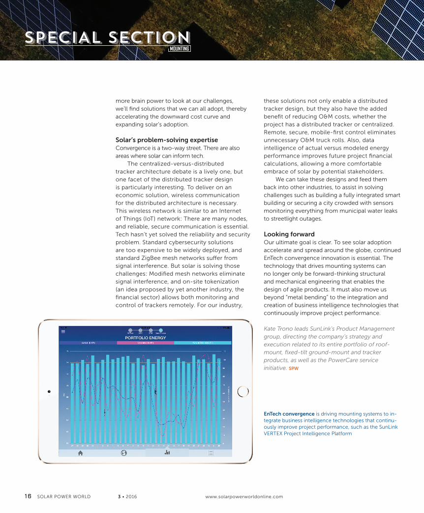
EnTech convergence is driving mounting systems to in-tegrate business intelligence technologies that continu-ously improve project performance, such as the SunLink VERTEX Project Intelligence Platform
Mounting Special Section 2-16_Vs2SB.indd 16 3/7/16 5:01 PM
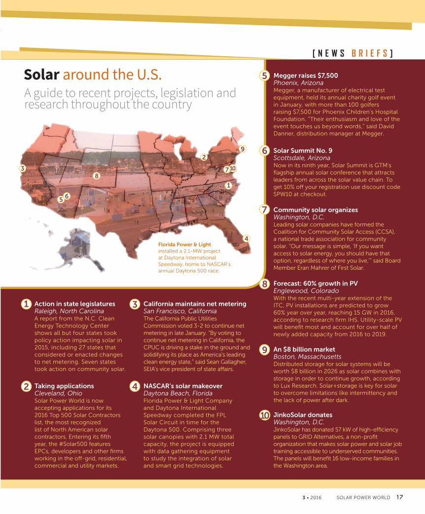
California maintains net meteringSan Francisco, CaliforniaThe California Public Utilities Commission voted 3-2 to continue net metering in late January. “By voting to continue net metering in California, the CPUC is driving a stake in the ground and solidifying its place as America’s leading clean energy state,” said Sean Gallagher, SEIA’s vice president of state affairs.
Forecast: 60% growth in PVEnglewood, ColoradoWith the recent multi-year extension of the ITC, PV installations are predicted to grow 60% year over year, reaching 15 GW in 2016, according to research firm IHS. Utility-scale PV will benefit most and account for over half of newly added capacity from 2016 to 2019.
An $8 billion marketBoston, MassachusettsDistributed storage for solar systems will be worth $8 billion in 2026 as solar combines with storage in order to continue growth, according to Lux Research. Solar+storage is key for solar to overcome limitations like intermittency and the lack of power after dark.
Action in state legislaturesRaleigh, North CarolinaA report from the N.C. Clean Energy Technology Center shows all but four states took policy action impacting solar in 2015, including 27 states that considered or enacted changes to net metering. Seven states took action on community solar.
Solar Summit No. 9Scottsdale, ArizonaNow in its ninth year, Solar Summit is GTM’s flagship annual solar conference that attracts leaders from across the solar value chain. To get 10% off your registration use discount code SPW10 at checkout.
Community solar organizesWashington, D.C.Leading solar companies have formed the Coalition for Community Solar Access (CCSA), a national trade association for community solar. “Our message is simple, ‘If you want access to solar energy, you should have that option, regardless of where you live,’” said Board Member Eran Mahrer of First Solar.
Taking applicationsCleveland, OhioSolar Power World is now accepting applications for its 2016 Top 500 Solar Contractors list, the most recognized list of North American solar contractors. Entering its fifth year, the #Solar500 features EPCs, developers and other firms working in the off-grid, residential, commercial and utility markets.
NASCAR’s solar makeover Daytona Beach, FloridaFlorida Power & Light Company and Daytona International Speedway completed the FPL Solar Circuit in time for the Daytona 500. Comprising three solar canopies with 2.1 MW total capacity, the project is equipped with data gathering equipment to study the integration of solar and smart grid technologies.
Megger raises $7,500Phoenix, ArizonaMegger, a manufacturer of electrical test equipment, held its annual charity golf event in January, with more than 100 golfers raising $7,500 for Phoenix Children’s Hospital Foundation. “Their enthusiasm and love of the event touches us beyond words,” said David Danner, distribution manager at Megger.
1 3
3
5
5
6
6
8
9
9
7
78
2
2
4
4
1
3 • 2016 SOLAR POWER WORLD 1 7
[ N E W S B R I E F S ]
Solar around the U.S.A guide to recent projects, legislation and research throughout the country
Florida Power & Light installed a 2.1-MW project at Daytona International Speedway, home to NASCAR’s annual Daytona 500 race.
JinkoSolar donates Washington, D.C.JinkoSolar has donated 57 kW of high-efficiency panels to GRID Alternatives, a non-profit organization that makes solar power and solar job training accessible to underserved communities. The panels will benefit 16 low-income families in the Washington area.
10
10
News in Brief_1-16_Vs1.indd 17 3/7/16 5:04 PM

P A N E L P O I N T S KELLY PICKERELASSOCIATE EDITOR
GTM Research assembled a list of marketed integrated module partnerships (including both AC modules and smart modules), current as of November 2015.
The SMART MODULE MARKET is gaining momentum
Smart modules—essentially solar panels with “smart,” module-level power electronics—have seen a slow rise in popularity. But that could change fairly quickly, according to GTM Research, which is predicting shipments of smart modules and related AC modules (panels with pre-installed microinverters) to grow from 73 MW in 2014 to 1 GW in 2020, an almost 14-fold increase. What’s fueling this growth?
What is a smart module?These intelligent packages have grown from being just panels equipped with power optimizers. Today’s good smart modules involve any type of module-level electronics with functions like remote monitoring, module-level shutdown, voltage limiting, increasing power harvest and more.
“The way we think of smart modules is anything that has something built into it that does more than just sit there and generate power from the sun,” said Parjanya Rijal of Trina Solar, which has its own smart module: Trinasmart.
Many of the top module manufacturers have a smart line, including JA Solar, Jinko Solar, Canadian Solar, Upsolar and Trina Solar. Most have partnered with optimizer manufacturers Tigo Energy or SolarEdge to obtain that smart advantage. ET Solar has its Cell Optimizer Module, which includes an integrated power regulator on each cell-string within the solar module (no external power optimizer is needed).
“Smart modules are something where it differentiates a module,” Rijal said. “In an industry where basic solar modules used to use bankability to differentiate, there’s more and more companies that claim that. This is a way to continue to innovate and be different from all the manufacturers out there.”
Power optimizers are still the dominant add-on for smart modules, said Lior Handelsman, founder and vice president of marketing and product strategy for SolarEdge.
“With system owners demanding more from their PV systems and installers demanding more in terms of installation efficiency, module manufacturers can better satisfy the current market requirements by embedding power optimizers,” he said.
What has prevented growth, and why is that changing?There is an obvious price difference between traditional modules and the smart variety. With added monitoring and hardware comes added costs and the potential for added import taxes. As the market matures, GTM Research expects product markups to fall.
“Many module manufacturers were paying import tariffs on their finished goods. Integrating power optimizers into the modules meant that they also had to pay tariffs on the power optimizer, thus raising the cost,” Handelsman said. “This offsets the value of integration. We are starting to see more strategies from module manufacturers that limit the impact of the import tariff, meaning that these integrated products are starting to drive cost reduction for installers.”
There have also been some hiccups in relaying to end-users the real benefits smart modules can bring. People who thought solar couldn’t work on their houses because of huge oak trees casting shade now have real generation capability with smart modules.
1 8 SOLAR POWER WORLD 3 • 2016 www.solarpowerworldonline.com
Tigo’s optimizer can be added to panels to make them “smart.”
Panel Points_2-16_Vs2kp.indd 18 3/7/16 5:13 PM

P A N E L P O I N T SP A N E L P O I N T S
Module-level power electronics are expected to become more prevalent in the module market. The global smart and AC module forecast estimates significant growth over the next few years.
“People will see that these technologies work, there will be a longer track record of increasing your energy production, a track record of them working properly,” Rijal said. “On the cost side, we’re moving along the learning curve—lower cost both because of learning how to do that better and increasing volume.”
Some code changes will also bump up smart module adoption. The 2017 NEC updates effectively require module-level shutdown, which then essentially forces installers to use module-level power electronics to reduce voltages. Opinions are mixed on the safety issues considered with the new code standards, but it does appear that smart modules will become necessary commonplace on new rooftop installations.
“Regulations like NEC 2014 rapid shutdown are driving installers and first responders to improve PV safety,” Handelsman said. “Solutions like integrated power optimizers allow module manufacturers to offer a solution that will address these safety concerns out of the box without the need for additional equipment or costs.”
It’s also likely that other industry requirements could spark the rise in smart module popularity.
“We particularly see our module integrated solution as a platform for not just the technology that’s available now—like rapid shutdown, longer strings, monitoring—but a way to kind of future-proof our systems,” Rijal said. “It’s a platform that you can integrate whatever technology that comes out in a few years, as well.”
Bottom line: Now is an ideal time in the market for smart modules.
“Cost reduction for the installer is a constant battle. Since the integrated modules can reduce hardware costs and decrease installation times, they have the potential to drive costs down,” Handelsman said. “At the same
time, smart modules also have the potential to create differentiation for module manufacturers in a highly commoditized and competitive market. An intersection of cost reduction and differentiation creates a highly attractive environment for smart modules going forward.” SPW
People will see that these technologies work, there will be a longer track record of increasing your energy production, a track record of them working properly.
3 • 2016 SOLAR POWER WORLD 1 9
Panel Points_2-16_Vs2kp.indd 19 3/7/16 5:14 PM

I N V E R T E R I N S I D E R KATHIE ZIPPMANAGING EDITOR
INVERTERS AND BATTERIES become better friends
2 0 SOLAR POWER WORLD 3 • 2016 www.solarpowerworldonline.com 3 • 2016 SOLAR POWER WORLD 2 1
As storage and intelligent power conversion grow increasingly important to grid function and solar energy availability, manufacturers are more closely combining technologies through partnerships and new products. Below are excerpts from three recent conversations we’ve had with companies on this topic. Be sure to read and listen to the full versions of each one on solarpowerworldonline.com.
In light of Ideal Power’s recent partnerships and new solar+storage solutions, John Merritt, director of applications engineering, provided more insight into the company’s technology and business model.
John Merritt
Michael Dixon
Director of Applications
Engineering, Ideal Power
Renewable Products
Marketing Manager,
Sensata Technologies
with IDEAL POWERQ&A
Q&A
Partnering to better solar+storage systems
A closer look at Magnum Energy’s microinverter and battery-based inverter charger
SPW: How and why are you working with inverter manufacturers like KACO new energy, and storage companies, such as Sharp, Green Charge Networks, sonnen and Aquion Energy?
Merritt: As part of Ideal Power’s capital-efficient business model, we have contracted our manufacturing to an outside partner to keep our costs low. Our systems are being manufactured and white labeled for KACO new energy to sell under its own brand. Our agreement with KACO also allows the company to use our technology to develop its own differentiated products and integrated energy storage systems. This allow us to add an additional revenue stream without the costs associated with materials, manufacturing and shipping.
First and foremost, Ideal Power is a technology company. Our focus is to deliver efficient, flexible and cost-effective power converter solutions
(whether Ideal-branded, white labeled or converter IP) to our integration partners, who then bundle our technology with batteries, controls and BoS components. These partners provide additional value-add, such as analytics and reporting, installation services and project financing. Entering the integration business is not part of our competency or business strategy and would create competitive friction with our end customers. We do, however, provide technical support and training for our integration partners. For instance, we test with our battery manufacturer partners to ensure compatibly with our technology. This support work benefits all parties in the energy-storage supply chain.
Sensata Technologies recently introduced the Magnum Energy MicroGT 500 inverter. We contacted renewable products marketing manager Michael Dixon to find out more.
SPW: What exactly is a battery-based inverter?
Dixon: A battery-based inverter is a bi-directional inverter plus battery charger that serves multiple purposes. It converts DC to AC power but also allows AC input from multiple power sources so it can augment power from the grid for backup power. It can
with SENSATA
Inverter Insider_2-16_Vs2KZ.indd 20 3/7/16 5:27 PM

I N V E R T E R I N S I D E R
3 • 2016 SOLAR POWER WORLD 2 1
Darren Hammell
President, Princeton Power
(Dixon continued) also charge the battery. To add storage to an existing grid-tie PV inverter installation, the battery-based inverter would be AC coupled to the AC output of a grid-tie inverter, in this case our microinverter.
MicroGT is a 500-W microinverter with dual MPPT PV inputs. It is designed for excellent compatibility and seamless operation in AC coupled applications using Magnum off-grid MS-PAE series battery-based inverters/chargers. While many microinverters are connected one-per-panel, the MicroGT supports two PV panels each and is daisy chainable. The output of one inverter is connected to the inverter next to it instead of connecting to a trunk cable or combiner box. Our microinverter communicates with our battery-based inverters, which enables better care and maintenance of the battery. Because the MicroGT is designed to seamlessly integrate with our inverter/charger, customers who wish to add storage will find it easy to upgrade at an affordable price. This combination of features is unique in the market.
In this podcast, we spoke with Darren Hammell, president of Princeton Power, who started his energy storage company in his dorm room. The company is now celebrating 15 years of business. Hammell shares what has made Princeton Power successful, his view of the storage market and advice for other solar startups.
Solar Speaks: How a Princeton student found his way into solar storage
DOWNLOAD ON DEMAND: bit.ly/1VN6rBH
PODCAST ALERT
SPW: Can you explain what Princeton Power offers and how you came to develop this technology?
Hammell: At heart, our company manufactures large-scale power converters for business and industrial-sized applications. But we’ve also developed a suite of software that controls batteries, solar arrays and other assets you may find in a solar storage system. We’ve also developed a full system-level controller that we call the energy management operating system. Additionally, we offer design and commissioning services.
In the early days we thought we had a neat idea for doing power conversion. We hoped it was something the world needed in some way, but it took a few years until I hit on the idea of renewable distributed energy systems. The need became pretty obvious. Then, working on batteries was the next step as we realized storage systems were going to be a huge part of making renewables more effective in our electric grid. SPW
NEXT GENERATIONSELF-GROUNDING SYSTEM
SunModo, Corp.Vancouver, Wash., USA
The Newest Industry Standard is Here! Professional solar installation just became easier and more secure. SunModo’s self-grounding product line simplifies your solar installations with a complete line of solar mounting products.Meets NEC 690.47 and UL 2703.
SUNMODO’S SELF-GROUNDING SYSTEM
FEATURING: Self-Grounding Pins, Rail Splices, Lugs, Portrait Mid Clamps, Landscape Mid Clamps, and Landscape End Clamps!
For more information and product detail: www.sunmodo.com
Self-Grounding Pins
Inverter Insider_2-16_Vs2KZ.indd 21 3/7/16 5:27 PM
S E R V I C E S KELLY PICKERELASSOCIATE EDITOR
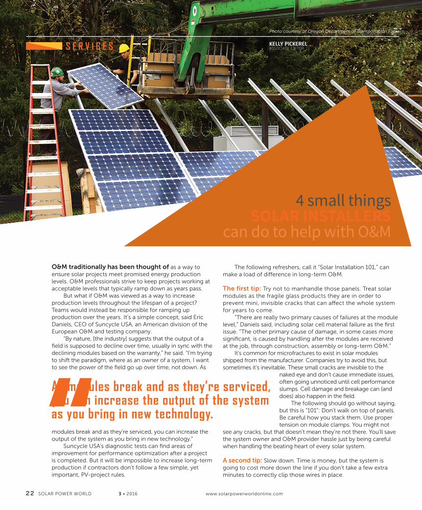
4 small things SOLAR INSTALLERS
can do to help with O&M
2 2 SOLAR POWER WORLD 3 • 2016 www.solarpowerworldonline.com
Photo courtesy of Oregon Department of Transportation Flickr
O&M traditionally has been thought of as a way to ensure solar projects meet promised energy production levels. O&M professionals strive to keep projects working at acceptable levels that typically ramp down as years pass.
But what if O&M was viewed as a way to increase production levels throughout the lifespan of a project? Teams would instead be responsible for ramping up production over the years. It’s a simple concept, said Eric Daniels, CEO of Suncycle USA, an American division of the European O&M and testing company.
“By nature, [the industry] suggests that the output of a field is supposed to decline over time, usually in sync with the declining modules based on the warranty,” he said. “I’m trying to shift the paradigm, where as an owner of a system, I want to see the power of the field go up over time, not down. As
modules break and as they’re serviced, you can increase the output of the system as you bring in new technology.”
Suncycle USA’s diagnostic tests can find areas of improvement for performance optimization after a project is completed. But it will be impossible to increase long-term production if contractors don’t follow a few simple, yet important, PV-project rules.
The following refreshers, call it “Solar Installation 101,” can make a load of difference in long-term O&M.
The first tip: Try not to manhandle those panels. Treat solar modules as the fragile glass products they are in order to prevent mini, invisible cracks that can affect the whole system for years to come.
“There are really two primary causes of failures at the module level,” Daniels said, including solar cell material failure as the first issue. “The other primary cause of damage, in some cases more significant, is caused by handling after the modules are received at the job, through construction, assembly or long-term O&M.”
It’s common for microfractures to exist in solar modules shipped from the manufacturer. Companies try to avoid this, but sometimes it’s inevitable. These small cracks are invisible to the
naked eye and don’t cause immediate issues, often going unnoticed until cell performance slumps. Cell damage and breakage can (and does) also happen in the field.
The following should go without saying, but this is “101”: Don’t walk on top of panels. Be careful how you stack them. Use proper tension on module clamps. You might not
see any cracks, but that doesn’t mean they’re not there. You’ll save the system owner and O&M provider hassle just by being careful when handling the beating heart of every solar system.
A second tip: Slow down. Time is money, but the system is going to cost more down the line if you don’t take a few extra minutes to correctly clip those wires in place.
As modules break and as they’re serviced, you can increase the output of the system as you bring in new technology.
Services_2-16_Vs3.indd 22 3/7/16 6:11 PM
MODULAR SYSTEMFlexibility, delivery performance & complete motion solutions. Standardized motors, gears and modular accessories are available with a higher degree of flexibility to address specific requirements in complete motion solutions.
1500 Bishop Ct - Mt Prospect, ILCall: 773-289-5555
MOST ADVANCED TRACKING SOLUTIONSAll-in-One Motion Solution For Solar Trackers
» Motor | Gearhead | Controller | Fieldbus» Integrated Inclinometer
Motion Solutions Made, Effi cient, Maintenance-Free and on lowest cost of Ownership. Now Available in One Compact Unit.
Dunkermotoren 3-16.indd 7 3/7/16 7:22 PM

2 4 SOLAR POWER WORLD 3 • 2016
S E R V I C E S
“During the field install, the tendency is to try and do it fast,” Daniels said. “It accomplished the task, you connect the wires where they need to be connected, but you don’t necessarily want to have wires coming out of the sides of boxes where rain over time can leak in and have other problems.
“One of my basic pet peeves is wire and cable management,” he continued. “Some EPCs do a fantastic job. They spend the money to get it right in the first place. Over time, 20 years of a cable on the back of a module that is exposed to an environment, swinging in the free air, chaffing or yanking on the junction box, is just not a good idea. For the sake of a fraction of a penny … There are easy, low-cost things to do to make sure the system works well over time.”
Another freebee: Design a project with maintenance in mind. And we’re not talking just solar-specific maintenance—you never know what kind of maintenance will be necessary on the site. It might not be raining now, but what happens during a flood? Or, that HVAC system might need to be accessed on the roof amidst all those solar panels.
“I’m often looking at systems where the design of a system has inherently made servicing it a problem,” Daniels said. “A lot of design seeks to maximize the watts in a field or rooftop, and as a result, there is little attention being given to design for service. Systems do need to be repaired. People need to be on the rooftop for other reasons besides the solar array. People will walk across the solar array or take the shortest path to clear roof drains. It’s not the [solar] installers fault per se, but when you’re designing the system, design for maintenance, whether that’s building maintenance, site maintenance. Things outside the immediate array can ultimately affect the array.”
Designed plans always have the best intentions, but once out in the real world, things change. Daniels said he understands this, but it doesn’t hurt to think twice before sticking an inverter pad where water is going to collect just because that’s the easiest option at the time.
233A South Street | Hopkinton, MA 01748 | 800.539.3939
www.ninefasteners.com
NFI-1306-V9090º oriented clip intended to secure two USE-2 wires, up to .20”diameter, to standard module frame.
DCS-1306Designed to secure two USE-2 wires,up to .20” diameter, to module frame.
NFI-1461Designed to secure two Enphasetrunk cables to module frame.
NFI-146290º oriented clip designed to secure twoEnphase trunk cables to module frame.
NFI-1463NEWLY designed clip to secure a singleEnphase trunk cable to module frame.
DCX-2452ADesigned to secure two Enphase trunkcables on to most rail/racking systems.
For FREE product samples, please reach out to Vin [email protected] or 800.539.3939
DCS-1307Designed to secure two PV wires, upto .30” diameter, to module frame.
182804 Nine Fasteners Ad:Layout 1 6/4/15 1:27 PM Page 1
Services_2-16_Vs3.indd 24 3/7/16 6:11 PM

3 • 2016 SOLAR POWER WORLD 2 5
P A N E L P O I N T SS E R V I C E S
Groups like Solar Energy International and the North American Board of Certified Energy Practitioners (NABCEP), along with many solar component manufacturers, offer training courses throughout the country and often on traveling roadshow-type schedules. It might be difficult to see how what you do today affects the bigger picture in 25+ years, but it’s necessary to be at your best so solar systems can perform at their best.
Daniels said installers not directly associated with O&M can help out a lot by just doing the absolute best job they can at the very start.
“If you look at the beginning of a project, you have ever increasing opportunities now to ensure that what goes into your site and project is of first-grade quality,” he said. “There is an opportunity to try and reduce the glide path down of watts or energy out of the site and reverse that to use maintenance as an opportunity to increase output.”
When O&M providers get to spend less time fixing problems that started during construction, they’re able to find ways to increase system output and make solar even more attractive to the masses. SPW
“When you’re designing the system, design for maintenance, whether that’s building maintenance, site maintenance.”
Ph
oto
co
urt
esy
of
Way
ne
Nat
ion
al F
ore
st F
lickr
“[Installers] install a system, optimize it and get off the jobsite quickly,” he said. “I see changes to design that are not necessarily recommended by the inverter manufacturer or others that have provided components. Cables coming into areas of the inverters that they shouldn’t be. You need to tuck things out of the rain, you need to tuck things out of the sun.”
Quick changes to properly designed plans might lead to more time spent on maintenance.
And finally: Take training and education seriously. If you aren’t sure how to connect something, don’t take shortcuts to get it done. There are plenty of solar training courses for your benefit.
“A lot of installers might be more familiar with AC than DC, so you see a lot of AC-designed componentry making its way into fusing,” Daniels said. “That’s not something that I see typically on the bigger utility jobs [with] more experienced EPCs involved. Smaller systems have a much broader base of people doing them.”
Services_2-16_Vs3.indd 25 3/7/16 6:12 PM

S T O R A G E KATHIE ZIPPMANAGING EDITOR
2 6 SOLAR POWER WORLD 3 • 2016 www.solarpowerworldonline.com
Finding COMMON GROUND on solar storage standardsStorage technology is crucial to the growth of solar, but its deployment could be challenging. Grid-connected energy storage lacks clear expectations and standards among manufacturers, so how can developers know their systems will operate correctly and safely?
“It’s a very confusing marketplace,” said Davion Hill, energy storage leader for North America at DNV GL. “There are IEC, UL and various other standards for batteries, but none say why or how
you should use them—they’re just there. Putting myself in the shoes of developers or battery manufacturers, I can totally understand their confusion. We wanted to develop something to
help navigate that path.”Knowing successful storage
implementation would require clarity and agreement on rules and regulations, DNV GL initiated the GRIDSTOR joint industry project.
GRIDSTOR aimed to accelerate implementation of grid-connected storage systems through a recommended practice for system safety, operation and performance. DNV GL invited a diverse selection of industry stakeholders—
including major international suppliers, end users and regulators—to join the consortium. Together, they worked to fill gaps left by existing standards and create internationally-recognized guidelines.
The consortium examined more than 150 standards—many from a DOE-published inventory—and listed them under sections of safety, operation and performance. The recommended practices are generic for all types of grid-connected electricity storage systems, with an emphasis on high-energy batteries.
“We didn’t just want to point to industry standards, but explain where, how and why to use them,” Hill said.
The BEST test Though the GRIDSTOR recommendations are meant to be used by any manufacturer or testing agency, DNV GL also offers its own GRIDSTOR compliance, qualification and customized testing services in its BEST (battery and energy storage technology) facility in Rochester, New York.
For battery manufacturers, DNV GL can perform qualification tests and award an IEC certificate just like other accreditation centers, but Hill explained the center’s capabilities go much further.
“Many times manufacturers want to test how they’re better or different than their competition,” he said. “Not only can we accredit them to the same
Get the GRIDSTOR Recommended Practice?The DNV GL Recommended Practice on grid-connected energy
storage systems is available freely, with no obligation, at:
www.dnvgl.com/rules-standards.For more info on how we can help you get the most from
GRIDSTOR, please contact us at: [email protected]
Its system-level methodology takes into account the grid
connection, components and sub-components, to offer you a
clear and comprehensive structure. And since it was built on
insight from a wide array of industry stakeholders, you can be
confident that the guidelines and recommendations reflect the
real marketplace and your real needs.Examples of what the GRIDSTOR Recommended Practice
can do for youSafety ■ Minimise the risk of injury or damage by the system to itself
or to property ■ Evaluate the entire system using the international FMEA/
Bowtie analysis methodologies, put into the appropriate
perspective for various technologies Operation: ■ Standardise how the lifetime of the storage system is
determined ■ Provide a methodology for defining and measuring key
parameters such as State of Charge and State of Health
■ Ensure optimal monitoring and control of the system and its
components
Performance: ■ Ensure your system performs against predefined guidelines
and fulfils obligations as set in purchase contracts
■ Evaluate system efficiency and determine which subsystems
to include, under which environmental conditionsBringing international stakeholders together
As a thought leader with extensive experience in the renewable
energy market, DNV GL was the catalyst in bringing
international industry stakeholders together to speed up the
process of developing a recommended practice. At DNV GL,
we believe that actions like these support the entire industry
and the global community. The Recommended Practice has
been developed in cooperation with JSR Micro, REDT Energy
Storage, Energy Canvas, Joulz, Institute for Mechatronic Systems
in Mechanical Engineering (Technische Universität Darmstadt),
KEMA Nederland B.V., Utrechtseweg 310-B50, 6812 AR Arnhem, the Netherlands
Tel: +31 26 356 9111, Registered Arnhem 09080262 www.dnvgl.com
Institute for Power Generation and Storage Systems (RWTH
Aachen University) and Cumulus Energy Storage, and has been
reviewed by 36 organisations across the globe.DNV GL helps you get the most from the GRIDSTOR
Recommended PracticeWith so many benefits to the Recommended Practice, you want
to be certain you are maximising the possibilities. But your own
project will always be unique. That’s why DNV GL offers you
tailored support to get the most from GRIDSTOR. If you are a manufacturer for example, we can help you
apply the recommended practice to your system and check
your compliance. If you are an aggregator or user, we can
support you in creating a Request for Proposal (RfP) that will
ensure your expectations are met. And, as always, we offer you
the peace of mind of working with a proven partner with an
excellent international reputation.Based on the GRIDSTOR Recommended Practice, we can
support you with technical due diligence, owner’s engineering,
market assessment, technology reviews and testing. Benefits of DNV GL’s services ■ Ensure the energy storage system you will buy, sell or operate
is compliant with the GRIDSTOR Recommended Practice
■ Determine which actions and measures can be taken to
improve its safety, operation and performance
■ Demonstrate to your stakeholders that your technology meets
their expectations
SAFETYOPERATION
PERFORMANCE
FMEA/Bowtie analysisRisks and mitigationDesign consequencesProcedures & documentation
MonitoringControl
Grid connectionEnvironmental analysis
DefinitionsConditions
MeasurementLife cycle costs
APPROACHSystem and component levelTechnology-agnostic and -specificApplications and life cycle phasesStandards, guidelines and regulations
© xxx
SAFER, SMARTER, GREENER
GRIDSTOR RECOMMENDED PRACTICE FOR GRID-CONNECTED ENERGY STORAGE SYSTEMS
Your one-stop guideline for safe and sustainable grid-connected energy storageDeploying grid-connected energy storage systems creates challenges for users and manufacturers alike. Without clear expectations and standards, how can you prove the system operates correctly and safely? The GRIDSTOR Recommended Practice (RP) offers a blueprint for an independent quality guarantee of the safe implementation and operation of your energy storage.
ENERGY
A global initiative from an international consortium, the GRIDSTOR Joint Industry Project has been pivotal in defining grid-connected energy storage and quality considerations that can impact successful deployment. The resulting Recommended Practice (DNVGL-RP-0043) brings together the most important and relevant standards and guidelines as well as industry experience into a single document. It provides simple, clear and practice-based guidance on energy storage safety, operation and performance that is in harmony with all of those various standards.
The GRIDSTOR Recommended Practice is valid for all applications, on all levels from component to system, covering the entire energy storage system lifecycle. You can use GRIDSTOR as your single, standalone, all-encompassing guideline. And in DNV GL, you have a knowledgeable and highly experienced partner to support you in following the guidelines and certifying compliance.
Real quality needs of all stakeholders The guidance in the GRIDSTOR Recommended Practice comes from an international consortium working together to create a consensus. By incorporating the insight, knowledge and authority of major industry players, the document answers the real quality needs of users, aggregators and manufacturers for grid-connected energy storage systems.
The scope of this recommended practice goes far beyond any existing standards in covering the key quality criteria of safety, operation and performance. By using it, you can ensure that your expectations are in sync with everyone else involved, throughout the value chain.
Benefits of using the GRIDSTOR Recommended Practice ■ Be confident your energy storage system meets expectations for safety, operation and performance
■ Simplify tendering, by using standard definitions for lifetime, energy capacity, state of charge, etc.
■ Clearly define the scope of responsibilities of each player for a smoother process, better relationship and more satisfactory outcome
■ Create comprehensive RfPs that reflect the real systems and specifications
A fresh approach to standardsThe Recommended Practice addresses a broad range of energy storage technologies, such as Li-ion batteries, lead-acid batteries, redox flox batteries, flywheels and more. It is aligned with ongoing international standardisation activities, based on globally accepted regulations and best practices such as IEC, ISO and IEEE standards. The Recommended Practice will be periodically updated with new technologies.
Not only can we accredit them to the same certificate to which their competitor was just certified, but we can make testing conditions harsher, playing with aspects such as temperature, to test where they’re strong.
Storage_3-16_Vs3KZ.indd 26 3/7/16 6:21 PM

P A N E L P O I N T SS T O R A G E
certificate to which their competitor was just certified, but we can make testing conditions harsher, playing with aspects such as temperature, to test where they’re strong. We act as an independent lab to test their claim.”
Still, many of the center’s clients have been turned out to be banks and developers looking for evidence that storage solutions will meet project expectations.
Michael Mills-Price is head of DNV GL’s inverter testing business and also works at the storage facility. He explained how he assists clients at all levels of the solar market, from residential through utility, who are now aggressively looking at storage as part of their future portfolios.
“Let’s say a developer is looking to do business in Hawaii, which has unique environmental and regulatory conditions,” he said. “The developer wants to know if a given storage solution will perform safely and well enough for that facility (household or commercial building) to maximize the project economics over the stated warranty period. We can develop tests to give them a good idea if the technology will meet their expectations.”
DNV GL can test a system—battery, battery management system and inverter—even at the individual battery cell level. Testers examine battery degradation rates associated with various charge and discharge cycles within parameters, such
Storage_3-16_Vs3KZ.indd 27 3/7/16 6:21 PM

Solar Speedrack 3-16.indd 7 3/7/16 7:23 PM

3 • 2016 SOLAR POWER WORLD 2 9
P A N E L P O I N T SS E R V I C E S
as specific loads and temperatures, associated with the unique application. Results are analyzed and compared with previous results in the center’s ever-growing database. Analysts are able to use internal software to build a case for the customer.
“We can say, OK, if you’re developing solar on homes in Hawaii with these loads and this battery or storage system, you can expect this performance from onset through to year five or 10 of the warranty period,” Mills-Price said. “There truly are sweet spots for different battery chemistries in terms of how they’re operated. By evaluating a myriad of conditions specific to an application, we can make recommendations based on real lab testing data.”
Challenges to storage testing Unlike with inverter and module companies, Hill explained that most battery manufacturers still choose to do their own testing rather than have their product independently verified.
“Battery manufacturers have a strong competitive advantage in that they have been testing their battery cells longer than anyone,” he explained. “Doing in-depth, third-party testing is long and expensive—something not every manufacturer or developer is willing to take on.
If you are a developer looking at storage options in the middle of a time-sensitive contract and a battery manufacturer is showing you reams of their testing data, why would you stop and do independent testing?”
In these cases, DNV GL is often pulled in as the independent engineer to validate the data. “It’s not as good as running application-specific independent testing, but the market isn’t always asking for that right now,” Hill said.
Possible solutionsCurrently, independent testing procedures specific to solar storage don’t exist. Hill noted he has yet to see the solar industry push for these, but explained how other industries have. “Reliability is so key for the automotive market. You can’t develop a car, then leave your customers by the side of the road,” he said. “Their need to develop independent testing and validation was strong and early.”
Hill could, however, see a push in several instances. “Inverter and panel manufacturers could be a catalyst,” he said. “They’re used to showing developers third-party data and may come to demand this data from their battery vendors as well. Banks could also lead the way, asking developers to provide third-party testing data, who will in turn ask their vendors—whatever the bank says goes. Lastly, not to sound like a fearmonger, but usually a push comes after a crisis where millions of dollars are at risk. Then people say, ‘Why don’t we have this?’”
Hill agreed that if storage is going to be critical to solar, the industry
needs to think ahead. In the meantime, the GRIDSTOR can help lower the risk of field failures and lost profits.
“The industry really isn’t focused on operations, but when it is we’re in a good position to help.” SPW
There truly are sweet spots for different battery chemistries in terms of how they’re operated. By evaluating a myriad of conditions specific to an application, we can make recommendations based on real lab testing data.
Storage_3-16_Vs3KZ.indd 29 3/7/16 6:21 PM

S O F T W A R E CHRISTOPHER HOPPERCO-FOUNDER, AURORA SOLAR
Four steps to OPTIMIZE PERFORMANCE in shaded conditions
Assessing the impact of shading on system performance is an essential step in solar design. Solar designers often deal with shading issues like trees, chimneys and other obstructions, especially in the residential market. The question designers often face then is, given these conditions, how do we maximize system performance?
This is not an easy question to answer because shading can affect performance in a nonlinear way. However, an optimal solution can be found by following four steps.
Quantify. What’s the best way to quantify the impact of shading? Solar access measurements are useful as a guide but have limitations because they do not account for system configuration. Thankfully, modern, module-level simulation engines can accurately model the impact of shading on performance.
Explore. Systems come in countless combinations of size, location and configuration. Designers have several options to mitigate shading losses:
• Use string inverters and string the modules in a manner that minimizes shading losses. In some cases, simply changing the stringing configuration of a system can result in energy boosts of over 10%.
• Use module-level power electronics (microinverters or DC optimizers). In addition to mitigating the impact of shading by performing MPPT tracking on a module-by-module basis, they eliminate module mismatch losses.
• Increase the DC-to-AC ratio to reduce balance of system costs. Shading results in lower DC power, thus more panels can fit on an inverter without causing significant clipping.
• Explore the use of higher efficiency modules or modules with a higher Voc. A higher power density allows you to make better use of low-shade areas, whereas shorter strings are impacted less by shading.
• Vary the location and size of the system. Energy produced at different times of the day can have different values to the client.
Assess. Cost-benefit analysis ultimately leads to the “optimal” system design. But value is not always easy to determine. With time-of-use and tiered rates, the compensation for each kilowatt hour produced by the system can vary greatly. It can sometimes be better to place a system where there is more shade overall, but the system remains unshaded during high-value times. A detailed financial model that can handle these nuances is essential.
Automate. A detailed site assessment takes time. Without the ability to quickly assess multiple design variants, how many iterations can you afford to do? And how do you know if your design is really the optimal solution? Putting a streamlined process in place is crucial.
We believe software can empower solar designers to make these critical design decisions in an efficient manner. That is why we built Aurora to streamline the design process from remote shade
measurements and module-level performance simulations,
pricing and detailed financial analysis, all the way to proposal
generation. SPW
3 0 SOLAR POWER WORLD 3 • 2016 www.solarpowerworldonline.com
Software_2-16_Vs2SB.indd 30 3/7/16 6:25 PM

Baja 3-16.indd 7 3/7/16 7:27 PM

Driven by superior engineering, our roof mount systems are strategically designed to endure the toughest climates all over the globe. Rigorously tested against nature’s harshest conditions, from hurricane force winds to the most earthshaking seismic waves, our technology is tough enough to withstand any environmental threat, all while protecting the integrity of your building and keeping your power generation at a maximum. 415.306.9837
SUNLINK.COM
Discover the power of what’s possible, with SunLink.
Visit sunlink.com/roofmount to discover which SunLink solution is the perfect fit for your next project.
11925_Sunlink_Solar World Print Ad March/April.indd 1 2/12/16 3:10 PMSunlink 3-16.indd 7 3/7/16 7:28 PM

THE INSTALLATION
ISSUE
S P E C I A L S E C T I O N
Photo courtesy of Clean Energy Collective
POINTERS FORPROFITABLE, SAFE, EFFICIENT PROJECTS
We asked experts who are offering
technical training sessions at
the 2016 NABCEP Continuing
Education Conference—April 4 to
6 in San Diego, California—to share
some of their best tips for successful
installs. From battery safety to
project planning, the following
articles provide advice that can
help you achieve more profitable,
safe and efficient projects.
3 • 2016 SOLAR POWER WORLD 3 3
NABCEP section intro 3-16_Vs4.indd 33 3/8/16 1:02 PM

3 4 SOLAR POWER WORLD 3 • 2016 www.solarpowerworldonline.com
S P E C I A L S E C T I O N
Sections 690 and 705 of the National Electric Code have specific rules for sizing DC and AC conductors associated
with grid-tied PV systems. These requirements establish minimum conductor sizes that allow for safe operation in any installation.
The code doesn’t dwell on voltage drop considerations for PV inverters—there is no mention in either section; however, this is an important consideration for any installation, and particularly those requiring long cable runs on either the DC or AC side of the inverter.
PV inverters have a mandated normal operating voltage window, and excessive voltage drops in cabling (that effectively move the nominal operating voltage seen at the terminals of the inverter to one end of this window) can result in nuisance tripping of the inverter and an associated loss of generation.
Basic wire sizingThe NEC calls out different requirements for determining the base ampacity of a conductor depending on its location in the PV system:
• NEC Section 705.60 states the base wiring ampacity for AC conductors used to connect the inverter to grid must be based on 125% of the inverter nameplate current rating.
• NEC Section 690.8 states the base wiring ampacity for DC conductors carrying current generated by PV modules be based on 125% of the STC short circuit current capability of the string/array.
Once base ampacity values are determined, they must be further compensated to account for conditions of use per Section 310.15 of the NEC. These conditions of use include adjustments for ambient temperature, number of conductors in a raceway (conduit) and height of a conduit above a rooftop. Each of these factors, when applicable, increases the base ampacity to generate a minimum required ampacity value. The minimum wire size required can be found using Table 310.15(B)(16) in the NEC, depending on whether 75°C or 90°C rated copper or aluminum wire is specified.
Note that most inverters do not have the wiring terminals rated for aluminum wire, and so copper conductors must be specified.
Size inverter conductors to prevent big voltage drops
Figure 1: General case for calculating wiring voltage Drop - Assumes two identical conductors of length [ft] parallel to one another (e.g., in a raceway), with a constant current, IREF [A] flowing. Each conductor has the same resistance, RW [Ω] and each conductor will have an identical voltage drop due to wiring resistance, so, ΔV1 = ΔV2 = ΔV, so total wiring voltage drop is ΔVT = 2*ΔV = 2*I*RW
Figure 2: Equivalent circuit - If RW1 = RW2 = RW, then ΔV1 = ΔV2 = ΔV, the total wiring voltage drop is ΔVT = 2ΔV2 = 2*I*RW
Voltage drop considerationsThe minimum wire size obtained above doesn’t take into account voltage drops due to long runs between the array and inverter and between the inverter and the grid. For inverters, this is important: Every percentage of voltage drop results in a percentage of power loss from the inverter. While this may not seem like much, the cumulative energy (kWh) lost over the life of the system can be significant.
Most inverter manufacturers recommend a maximum of 5%
voltage drop for the system— typically 2.5% on either side of the inverter. On large systems, many designers specify an even tighter value of 3% total or less, to maximize the energy harvest.
Once the wiring size per NEC requirements is determined, the expected voltage drop in the wiring must be calculated and compared to the desired limit. SPW
ROY ALLENTECHNICAL SALES ENGINEER, ABB SOLAR INVERTERS
NABCEP section 3-16_Vs3SB.indd 34 3/7/16 6:56 PM

S P E C I A L S E C T I O N
3 • 2016 SOLAR POWER WORLD 3 5
Use four inches of flashing for leak-free solar
Generations of builders have installed asphalt shingle roofing on homes with chimneys, side walls and
other structures that introduce a vertical surface above the roof line. To preserve the integrity of the roof and prevent water leaks, roofers tend to install flashing next to these structures with at least a 4-in. overlap on the horizontal plane. As a manufacturer of roofing and solar photovoltaic systems, CertainTeed recommends that when installers affix modules to the roof, they treat the anchoring system like any other vertical rooftop structure and provide at least a 4-in. horizontal overlap.
Why 4 inches? The specification comes from the latest edition of the National Roofing Contractors Association Roofing Manual: Steep-slope Roof Systems, published in 2013. (NRCA will release a new version of the manual next year.) Though there isn’t necessarily empirical data showing the lateral distance that water can travel on a sloped roof, NRCA members have 45 years of accumulated knowledge and experience since the first publication of the manual. They know weatherproofing for shingle roof systems about as well as anyone.
The minimum recommendation of a 4-in. horizontal overlap, also known as
a side lap, applies to sloped roofs with a pitch of 4:12 or greater. Water can travel a greater lateral distance on lower slopes. If the pitch is less than 4:12, check with the roofing system manufacturer and be prepared to use flashing with a wider side lap.
For standard, rack-mounted photovoltaic systems, it’s always a good idea to read the product specifications and installation instructions prior to purchasing flashing to ensure that it is sized properly. With CertainTeed’s Apollo II integrated solar roofing system, there’s no need to search for compatible flashing. The product includes flashing designed with a 4-in. side lap.
Because there are many applications in asphalt shingle roofing that call for a 4-in. side lap, it is relatively easy to select appropriate flashing products for this purpose. The same cannot be said about selecting proper adhesives
for sealing the roofing material and the flashing. When choosing among the many available adhesives, focus first on products that are compatible with asphalt shingles. It will do no good
to purchase a high-quality adhesive if the manufacturer can’t vouch for its performance with your chosen material.
For flashing with asphalt shingles, including the Apollo II flashing, use an elastomeric, a tri-polymer, a
urethane or a roofing mastic that meets the ASTM D4586 Type II standard. This still leaves an endless variety to choose from, but you will have narrowed down the options to those adhesives that can support a leak-free installation for the lifetime of the system. SPW
CHRIS FISHERPV PRODUCT DEVELOPMENT LEADER, CERTAINTEED
Size an array according to battery capacity
Batteries used in DC coupled PV systems are typically rated at STC and at a discharge rate over a time period of 20 hours (C/20). The C represents the battery capacity and the 20
represents the number of hours of discharge time. The C rate can also describe the charge rate to return the discharged capacity to the battery. Generally, a C/5 rate, replacing the capacity in 5 hours, is commonly used when the objective is to quickly charge the batteries while utilizing inverter/chargers with generator or grid AC inputs.
PV nameplate performance, however, is never achieved largely due to the impeding factors such as system
Consult your battery manufacturer if in doubt of the optimal charge rate, absorb time and voltage set points of your battery bank.
NABCEP section 3-16_Vs3SB.indd 35 3/7/16 6:56 PM

S P E C I A L S E C T I O N
components, site conditions, sun hours, space and budget. More often than not, PV arrays are undersized to battery capacity and system loads. Industry veteran and author Ryan Mayfield suggests in his book, Photovoltaic Design and Installation for
Dummies, using the system’s battery capacity to quickly figure out and compare the minimum and efficient array size required to return the Amps to a battery bank. Mr. Mayfield explains a realistic and optimal rate of charge (current) harvested from a PV array
should land between the C/10 to C/20 values of the total battery bank Ah capacity. Example: See Chart SPW
ALAN SANTOS-BUCHPRODUCT SPECIALIST, MAGNUM ENERGY, A SENSATA TECHNOLOGIES BRAND
Choose the right cable ties
Many plastic-molded products, like cable ties for solar projects, are “UV-rated,” but there is a wide interpretation of what that means. Cable ties come
in different lengths, colors, widths and materials, but the “UV-rated” baseline for solar industry cable ties usually means they’re black. Cable tie resin is “natural” colored until a colorant, typically carbon black, is introduced into the manufacturing process. Carbon black is a major contributor to UV resistance of ties, and their longevity in the sun is dependent on the amount of carbon black used. So while using black cable ties for solar is the right way to go, the amount of carbon black really determines the ties’ lifespan.
With a lack of standards as to what “UV-rated” means, a tie could have as little as 0.03% carbon black and still make that claim. There have been many studies, originating with Bell Labs in the 1950s, that show around 2% carbon black as the optimum amount for extended life expectancies in outdoor wire applications. In addition to the amount of carbon black, smaller particle sizes and good particle distribution within the molded part also play a role.
Carbon black is considered a UV absorber because it takes the high-energy UV rays and converts them into heat before they can damage the polymer resin. UV resistance of molded plastics can be further improved with UV inhibitors. For example, HellermannTyton’s line of solar ties includes a UV inhibitor in addition to the 2% carbon black, which helps to further improve lifespans.
Industry testing for UV weathering should be standardized. An out-of-the-big-box cable tie could be “UV-rated” and UL listed, but this does not mean a long life in the field. The long-term impacts of these decisions can be drastic. Cables droop, rub and sway in the wind, which can lead to a wide variety of faults, production losses and thousands of dollars in unexpected O&M costs.
HellermannTyton uses a UV resistant adhesive, followed by base materials that are designed for long-term outdoor use. Any inks are pigment-based and designed for long-term outdoor durability. Where applicable, colors are either extruded into the material or laminated with thermal transfer printable films, designed for use with specialized ribbon inks that are carbon-based for extreme UV environments. HellermannTyton tests the materials both in actual outdoor use and in accelerated aging chambers to verify and document results. Each label construction is unique and designed for the environment involved.
Not all UV-rated products are created equal. To ensure long-term durability in wire management and identification, search out high quality, well made and intensely tested products. SPW
NICK KORTHPRODUCT MARKETING MANAGER OF THE ENERGIES DIVISION, HELLERMANNTYTON
3 6 SOLAR POWER WORLD 3 • 2016 www.solarpowerworldonline.com
Snake Tray® products are patent protected. Visit our website for speci c patent information.
Snake Tray products have built-in mounting hardware and nest together for cost-effective shipping and handling.
NEW ICE GUARD FOR SOLAR PANELS PREVENTS INJURIES DUE TO FALLING ICE
800.308.6788 ♦ www.snaketray.com ♦ Made in the USA
NewProduct
Revolutionary cable pathways drastically cut installation times to lower construction costs!
Snake Tray® Cable Management for Solar Installations
NABCEP section 3-16_Vs3SB.indd 36 3/7/16 6:56 PM

The Original POWERBALL
Truth is, you’ve already
WON THE LOTTERY
We simply invented a better way to collect your winnings.
www.solaredge.us
SolarEdge 3-16.indd 7 3/7/16 7:31 PM

S P E C I A L S E C T I O N
3 8 SOLAR POWER WORLD 3 • 2016 www.solarpowerworldonline.com 3 • 2016 SOLAR POWER WORLD 3 9
Initialize deep-cycle battery installs with a full charge
Properly initializing your deep cycle battery bank is key to system success. To start with, deep-cycle
batteries may not be fully charged when received. Self-discharge during transit and storage is normal. The amount of discharge varies due to storage time and ambient temperature. It is safe to assume, however, that batteries will need a refresher charge during installation.
cycle in balance with the rest of the bank. Recommended charging parameters may be unique to the brand and different battery types. Inverters and charge controllers are often pre-programmed with default set points that may not meet these specifications. Always refer to the manufacturer’s recommended voltage settings and adjust as required.
Electrolyte levels in flooded batteries should be checked prior to an initial charge to confirm the plates in each cell are fully covered. It is normal for electrolyte levels to drop slightly in some models as the battery case relaxes. In cells with low electrolyte levels, add distilled water until all plates are covered completely. It is important not to overfill cells as liquid levels will rise slightly during charging.
Specific gravity is the best indicator of a flooded battery’s relative state of charge, as well as overall health. Specific gravity readings are obtained with a hydrometer. Readings should be taken when the battery bank has completed charging and is resting in a float charge. Periodically, you may note specific gravity readings that vary between battery and/or cell, or are consistently low. This is often the result of insufficient charge current, deficit cycling
and/or sulfation build-up. Performing a corrective equalization on the bank will help properly balance and desulfate the battery bank, prolonging its life. Follow the manufacturer’s recommendations to complete this as part of a maintenance routine. Many systems allow programming of equalization charges on a set schedule. Be cautious of this. Frequently running a high voltage charge on healthy cells may cause them to burn out prematurely. SPW
JEFF MYLESMARKETING MANAGER, SURRETTE BATTERY COMPANY, MANUFACTURER OF ROLLS BATTERY
% CHARGE SPECIFIC GRAVITY
100 1.255-1.275
75 1.215-1.235
50 1.280-1.200
25 1.155-1.165
0 1.110-1.130
Specific gravity testing for deep-cycle batteries
Whether installing flooded, maintenance-free AGM or GEL models, battery banks should be placed on an initial balance charge using manufacturer-recommended charging parameters prior to cycling. This ensures each battery is fully charged and will
Select combiner boxes with NEC codes in mind
The combiner box plays a key role in a PV system. It consolidates the PV string source circuits into one or two output circuits to be
passed onto the power conversion system for inverting into AC and, in some systems, charging batteries. Combiner boxes also contain source circuit overcurrent protection devices required for safe system operation. Understanding and meeting the three new requirements of the National Electrical Code regarding combiner boxes for solar installations is straightforward when you select components designed with the code in mind.
NABCEP section 3-16_Vs3SB.indd 38 3/7/16 6:56 PM

S P E C I A L S E C T I O N
3 • 2016 SOLAR POWER WORLD 3 9
1. Rapid shutdown/NEC 690.12: New as of 2014, this specifies the requirement of a rapid shutdown system in PV systems in or on buildings. It is intended to give first responders the ability to safely control all PV circuits in such systems, as they are now required to have equipment that limits voltage between any conductors (including ground) to no more than 30 V and 240 VA within 10 seconds. Look for a combiner box system incorporating a contactor or some other disconnecting means in the box to de-energize circuits near the array. Also look for a disconnect to de-energize the system near the inverter or charge controller once a rapid shutdown event is triggered by a rapid shutdown initiator.
2. Arc-fault protection (AFCI)/NEC 690.11: This requires that all PV systems with DC source or output circuits operating at 80 V or higher have arc-fault protection. The best place to detect an arc is near its source, the PV array. By providing the AFCI capability in the combiner box, you narrow the possibility of where the arc fault occurred, decreasing the time it takes to find and fix the fault while minimizing the likelihood of time-consuming, costly, “nuisance tripping” from sources inside the home.
3. Local disconnect/NEC 690.15. This requirement states that “DC output of DC combiners mounted on roofs of dwellings shall have a load break disconnecting means located in the combiner or within 1.8 m (6 ft) of the combiner.” Furthermore, NEC section 690.12 also states that the disconnect must be manually operable. Make sure the combiner system’s external disconnect topology meets this requirement, which will save the installer time and money both during initial installation and throughout the life of the system. OutBack’s integrated combiner complies with all three requirements. SPW
ANDREA HIXSONPRODUCT SPECIALIST, OUTBACK POWER TECHNOLOGIES
To learn more call 760.301.5300
INNOVATION – QUALITY – DURABILITY – SERVICE – SUPPORT
Simple • Versatile • Fast • Durable
Flat Roof Ballasted or Attached ¬ High GCR / Energy Density
¬ Wind Tunnel Tested with SEAOC peer-reviewed results
UL 2703Bonding End
Clamp
UL 2703Bonding Mid
Clamp
Pre-Built Assemblies Delivered to Your Site:
NOW SHIPPING!
D DOME RAILLESSEast/West System
NABCEP section 3-16_Vs3SB.indd 39 3/7/16 6:56 PM
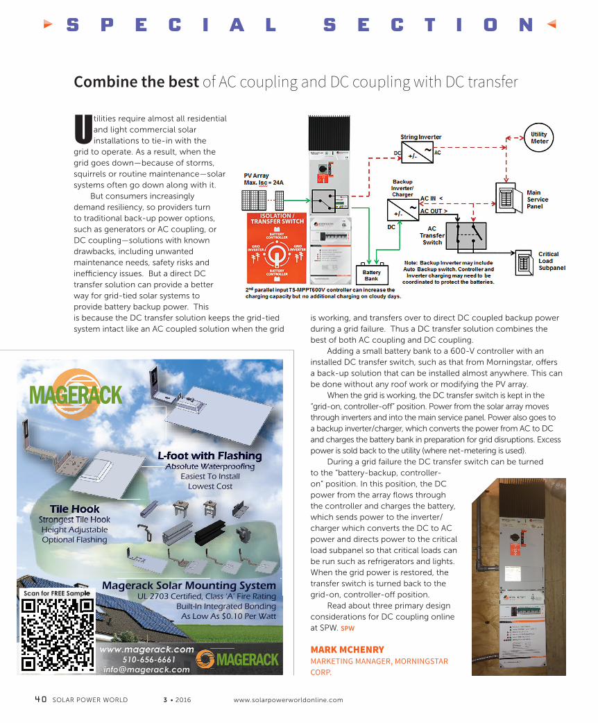
S P E C I A L S E C T I O N
Combine the best of AC coupling and DC coupling with DC transfer
Utilities require almost all residential and light commercial solar installations to tie-in with the
grid to operate. As a result, when the grid goes down—because of storms, squirrels or routine maintenance—solar systems often go down along with it.
But consumers increasingly demand resiliency, so providers turn to traditional back-up power options, such as generators or AC coupling, or DC coupling—solutions with known drawbacks, including unwanted maintenance needs, safety risks and inefficiency issues. But a direct DC transfer solution can provide a better way for grid-tied solar systems to provide battery backup power. This is because the DC transfer solution keeps the grid-tied system intact like an AC coupled solution when the grid
is working, and transfers over to direct DC coupled backup power during a grid failure. Thus a DC transfer solution combines the best of both AC coupling and DC coupling.
Adding a small battery bank to a 600-V controller with an installed DC transfer switch, such as that from Morningstar, offers a back-up solution that can be installed almost anywhere. This can be done without any roof work or modifying the PV array.
When the grid is working, the DC transfer switch is kept in the “grid-on, controller-off” position. Power from the solar array moves through inverters and into the main service panel. Power also goes to a backup inverter/charger, which converts the power from AC to DC and charges the battery bank in preparation for grid disruptions. Excess power is sold back to the utility (where net-metering is used).
During a grid failure the DC transfer switch can be turned to the “battery-backup, controller-on” position. In this position, the DC power from the array flows through the controller and charges the battery, which sends power to the inverter/charger which converts the DC to AC power and directs power to the critical load subpanel so that critical loads can be run such as refrigerators and lights. When the grid power is restored, the transfer switch is turned back to the grid-on, controller-off position.
Read about three primary design considerations for DC coupling online at SPW. SPW
MARK MCHENRYMARKETING MANAGER, MORNINGSTAR CORP.
4 0 SOLAR POWER WORLD 3 • 2016 www.solarpowerworldonline.com
www.magerack.com 510-656-6661
Scan for FREE Sample
Tile HookStrongest Tile HookHeight AdjustableOptional Flashing
Magerack Solar Mounting SystemUL 2703 Certified, Class ‘A’ Fire Rating
Built-In Integrated BondingAs Low As $0.10 Per Watt
MAGERACK
L-foot with FlashingAbsolute Waterproofing
Easiest To InstallLowest Cost
MAGERACK
NABCEP section 3-16_Vs3SB.indd 40 3/7/16 6:57 PM

Visit www.eagleview.com/solar tolearn more and request information.
866.447.3741 | www.eagleview.com
Measurement-Grade Datafrom Proposal through Design
EagleView is the leading provider of high-resolution aerial imagery and exterior property measurement reports. A fl eet of 90 aircraft fl ying year-round and proprietary, patented 3D technologies allows for delivery of accurate, detailed remote measurements including dimensions, orientation, tilt and obstructions. Delivered in a CAD fi le, it can be imported into existing workfl ows for precise proposals and designs.
Eagleview 3-16.indd 7 3/7/16 7:32 PM

S P E C I A L S E C T I O N
4 2 SOLAR POWER WORLD 3 • 2016 www.solarpowerworldonline.com
Consider connectors early in battery installations
Every energy storage system is different. To be fully prepared, it’s crucial to consider all wiring needs,
from essential cables and connectors to the time needed to connect them. Long before you unwrap your batteries, ask yourself these questions:
Six weeks before installation: Do I have the cables and connectors I need?
Each battery manufacturer has specific requirements for connecting and wiring batteries. The battery operations manual will contain essential information you must review before installation. We recommend that you closely read the operations manual at least six weeks before the day of installation. Some connectors or cables might have a long lead time, or they may not be available in your region. Give yourself adequate time to source
the needed accessories and order ahead to avoid installation delays.
This six-week mark is also the right time to make sure you have the tools you need. Depending on the components in your energy storage system, you may need access to tools
that aren’t in your everyday kit. For example, you may need a crimping tool for cables. Identifying these necessary tools in advance will give you ample time to find or order them.
Two weeks before installation: Have I planned for adequate wiring time and labor?
Some batteries may ship un bussed or not connected and will require action before installation. Aquion Energy’s Aspen 48M batteries, for example, are shipped un bussed, and the top cover must be removed to connect the fuses before installation. A second review of the battery operations manual at least two weeks before installation will help you plan for all time and labor related to cables and connectors. SPW
TERRY HOLTZSENIOR APPLICATION ENGINEER, AQUION ENERGY
Offer consumption monitoring to maximize system value
These days, most PV installs include system performance monitoring, but this is only half of the monitoring
solution necessary to verify that a sound investment decision was made. Often, renewable system owners begin to see lower energy bills and, in-turn, increase their energy usage—not always consciously. So, it is also important to measure the energy consumption of a location because it encourages responsible energy usage. A monitoring system that reports on energy production and consumption provides a complete picture of net usage and can lead to greater energy efficiency measures.
An incomplete picture costs time and money. A customer who feels his system is not producing what the installer estimated will place blame on the installer. The installer
sends a technician to the site, the system is verified to be producing as expected, and the customer continues to see higher than expected energy bills. Why? Because neither the installer nor the customer has identified the root cause. By monitoring the customer's consumption it is easy to see when, and if, there has been an increase. It alerts customers that their consumption habits have changed and quantifies the impact that change will have on their energy costs. Monthly utility bills can also indicate changes in habit, but they provide little information about what changes cost the customer and no immediate feedback when the customer attempts to correct the issue.
Customers with commercial buildings benefit the most from consumption monitoring. These customers tend to have higher energy bills, and installing solar
PV to offset energy costs is attractive to them. Frequently, commercial customers are charged for their peak demand in addition to energy. Peak demand charges are expensive and difficult to offset with PV because demand spikes do not always occur mid-day when solar is at its peak. A basic utility bill gives no insight into the cause of demand spikes. Real-time consumption monitoring is the best way to capture peak demand occurrences, and it can even be used in conjunction with control systems to flatten demand peaks. When real-time consumption monitoring is used in conjunction with a PV system, customers optimize the value of their efficiency investment. SPW
ED PANTZARACCOUNT MANAGER, EGAUGE SYSTEMS
NABCEP section 3-16_Vs3SB.indd 42 3/7/16 6:57 PM

S P E C I A L S E C T I O N
3 • 2016 SOLAR POWER WORLD 4 3
Ask these questions of solar+storage technology
Home energy storage is getting a lot of buzz lately as homeowners begin to see increasing energy
prices, changing energy tariff rates and a greater interest in energy independence.
It’s prime time for contractors selling “storage-ready” solar, but those in the market should recognize important design and installation considerations, especially as customer needs change.
Many of these design and installation issues are answered with smart preparation and analysis. The first step is a thorough evaluation of technologies, letting you select the best solution for your customers. Here are some questions to ask:
1. Does the solution allow for consumption monitoring? • You can’t say how much energy storage a customer will need if
you don’t know how much energy they use and when.2. Is it an off-the-shelf integrated solution, or is it necessary to cobble together a disparate suite of components? • Integration will be critical as
your customers’ needs change. Systems where PV generation communicates with energy storage enables greater optimized energy performance in the home and smart device integration moving forward.3. Does the solution make sense financially?
• Does the expected life of the system and product warranty support your ROI calculations? • Consider integration of secondary generation sources, such as generators, to provide more cost-effective energy needs for power outages of
longer duration. 4. Is the solution scalable? • Consider solutions that are scalable. If a customer’s energy analysis indicates they are best served with a 3.7-kWh storage solution but may need 7.4 kWh after two years, is there a solution that provides 3.7 kWh need in year one, yet is expandable to 7.4 kWh as an add-on?5. Is the solution safe? • Is the battery chemistry the best available for stationary, multi- cycle use?
Storage-ready systems should come with tools to help installers develop customer energy usage profiles, which will help them make proper sizing decisions. Systems should have the flexibility to integrate small and large battery capacities, scaling as necessary. Finally, storage systems should have a common communication framework that extends across the whole array. SPW
SHARON KIRKDIRECTOR OF WORLDWIDE TRAINING, ENPHASE ENERGY
Start at the sale to improve the installation process
A successful installation doesn’t begin when the crew arrives—it starts at first communication with the potential customer, setting the right expectations and getting them engaged in their new solar array. We
have found that the most successful solar installers follow these best practices to facilitate a smooth system sale and installation:
Triage. A quick site assessment, even before obtaining the customer’s energy usage, can help disqualify dead-end leads, which makes way for the promising ones. The most successful installers have a multi-step process of system validation, designed to minimize time and maximize throughput. The process combines sales and design tools such as HelioScope, along with
NABCEP section 3-16_Vs3SB.indd 43 3/7/16 6:57 PM

S P E C I A L S E C T I O N
4 4 SOLAR POWER WORLD 3 • 2016 www.solarpowerworldonline.com
supplemental tools like Energy Toolbase, OnGrid and UtilityAPI, to determine the ideal customers to pitch and how to approach them.
Share the workload. Installers are increasingly cross-training teams. When one person is out, others can step in and pick up the slack. This is often enabled by solar-specific software tools, as they are easier to use than general tools like AutoCAD or SketchUp. It is easier to teach your sales team to use HelioScope than it is to teach them to use AutoCAD.
Keep it simple. When discussing a potential solar array with a customer, more installers are replacing complex, multi-page proposals with streamlined, single-page documents. These single-page proposals keep the customer focused on the metrics that matter: their energy savings, their up-front investment (if any) and the company standing behind their installation.
Incorporate customer feedback to improve buy-in. Customers who have done their research may ask about
module or inverter selection or even the specific placement of the solar array on their roof. While this can be demanding of the sales team’s time, it is also a great opportunity to get the customer invested in the solar array. It is critical to have easy-to-use yet powerful sales tools, such as HelioScope, that you can pull up and use on-site with a customer—because you can still leave that first customer meeting with a signature. SPW
PAUL GRANA AND PAUL GIBBSCO-FOUNDERS, FOLSOM LABS
Plan the spacing of your rails from the
space of the bolt holes in the module frame
Build a headboard that will set both rails at equal lengths
Place wood blocks that will show location of rail connectors
Install wood blocks that will hold rails straight and square with each rail
Pre-assemble ground-mounts for faster installation
Ground-array jobsites can become congested, compromising timelines. Construction requires
a series of tasks to be completed as quickly as possible, including augering foundation holes, building sub-structures, pouring concrete and installing racking and modules.
The problem is most jobsites have minimal extra workspace. Having to wait until one task is completed before starting the next slows down overall construction.
Performing tasks off-site in a controlled environment greatly reduces the workload once on site.
The following steps will let you take your prefabricated assemblies to the jobsite and quickly install up to five modules at a time.
STEPS1. Use 2x4 and 2x6 lumber to build a jig
that will accommodate your rail and modules. Cut out locations where the rails will be placed and make sure they’re square.
2. Based on the tilt angle for your system, measure between the horizontal cross members of your sub-structures. The IronRidge Ground Mount Design Assistant will calculate the distance between the north and south piers. You can then use this
number to mark the rail connector locations in your jig.
3. Mark locations for microinverters or power optimizers.
4. Now that the jig is set up, begin assembling the rail connectors, microinverters and modules onto the rails. Wiring can also be completed at this time.
5. Take the first prefabricated assembly and install it onto the sub-structure to ensure rail connector locations are set properly.
6. If there are any issues, make adjustments to your jig before moving on.
7. Once you’ve completed building the assemblies, stack them for transport. We recommend using the cardboard from the module packaging in between each assembly to prevent damage. Use a flatbed trailer or truck for transporting the assemblies to the jobsite.
8. Once on site, a team can mount the assemblies on the sub-structures by installing the U-bolts into the rail connectors before moving onto final wiring. SPW
DAN FELIXTRAINING MANAGER, IRONRIDGE
NABCEP section 3-16_Vs3SB.indd 44 3/7/16 6:57 PM

May 11 - 12Omni Scottsdale Resort & SpaScottsdale, AZ
GREENTECH MEDIA’S 9TH ANNUAL SOLAR SUMMIT
Now in its ninth year, Solar Summit is GTM’s flagship annual solar conference that attracts leaders from across the solar value chain. Join us in Arizona for over two days of unrivaled networking opportunities and innovative, engaging panel sessions that will provide a unique mix of market intelligence and coordination among industry players. The two-day conference will present deep dives by top industry executives and thought leaders that will help attendees navigate the challenges in the market, as well as offer high level networking opportunities that enable sponsors to advance corporate business strategies.
Exclusive discount for Solar Power World readers! Enter code SPW10 at checkout to receive a 10% savings off your ticket price.
Learn more: www.gtmsolarsummit.comQuestions or looking to get involved? Contact: [email protected]
2016
Greentech 3-16.indd 7 3/7/16 7:33 PM

Learn install techniques for frameless modules
Frameless modules are inherently less expensive than traditional framed panels and have additional benefits
including better performance due to a lack of debris buildup at the edge of the module, no grounding requirements and both increased packaging density and less weight resulting in lower transport
and warehouse storage costs. Frameless modules are also appealing to those seeking aesthetics, as panels can appear to be “floating” on the roof.
A number of different installation techniques have been developed for frameless modules:
• For installations on pitched-roofs, frameless clamps with rubber guards have been designed to protect the glass and allow a traditional installation without a frame. Torque limiters should be used to prevent overtightening.
• For ballasted and ground-mount based systems, adhesive-based solutions have been developed, which eliminate the need for a clamp. Adhesives have been used for years in the construction industry for glass
skyscrapers, and they are produced by well-known manufacturers.
• Pre-assembly and pre-wiring of the modules in a controlled environment such as a warehouse can help decrease installation times and labor costs. Panel building blocks are then transported to the site. This can be extremely beneficial for projects that require prevailing wage labor rates.
• Automation and robotics can enable megawatt-per-day installations by small crews with significant BoS savings, accelerating cash flows and increasing ROI. This also reduces site grading, repair costs and abates dust and dirt buildup on the modules.
The combination of frameless modules and unique installation techniques can help you grow your business. SPW
SETH STULGISSENIOR MARKETING MANAGER, STION
See the opportunity on standing seam roofs
Is your metal roof solar-ready?This question has a quick
and easy answer of “Yes!” if it’s a standing seam metal roof, the most solar-ready roof out there. Standing seam clamps, such as those offered by S-5!, let installers mount on roofs without penetrating roofing material. With standing seam metal roofing panels, clamps secure the racks to the seam. Any time installers can avoid penetrating roofing material, they save time and money. This type of mounting also avoids potential leaks.
In addition, Metal Construction Association studies have shown that
standing seam metal roofing systems can last 60 years or longer in most environments, when properly installed. Crystalline solar panels have a life expectancy of 25 to 30 years, so the metal roofing system will often outlast the solar panels. Mounting on standing seams with nonpenetrating clamps eliminates concerns about replacing a roof riddled with holes when the solar array becomes dysfunctional. SPW
SHAWN HADDOCKTRAINING AND FIELD APPLICATIONS SPECIALIST, S-5!
S P E C I A L S E C T I O N
4 6 SOLAR POWER WORLD 3 • 2016 www.solarpowerworldonline.com
NABCEP section 3-16_Vs3SB.indd 46 3/7/16 6:58 PM

S P E C I A L S E C T I O N
3 • 2016 SOLAR POWER WORLD 4 7
Know where codes come from
Installing rooftop solar systems that consistently meet waterproofing code requirements rests on understanding the relationship between code,
roofing manufacturers and best practice guidelines. This knowledge can make the difference between passing and failing an inspection, and it helps maintain any roof warranties as well as reduce long-term liability.
Quick Mount PV created the Wheel of Accountability to help solar designers and installers better understand the relationships between relevant codes, standards and best practices—guidelines that impact rooftop structures and waterproofing.
The AHJ (authority having jurisdiction)—typically the local building department—is at the center of the wheel. The AHJ has final say on how rooftop solar systems will be installed. The AHJ is empowered to interpret codes and standards and enact special requirements that address climatic, geological, seismological or topographical conditions unique to an area.
OSHA establishes workplace safety requirements and can shut down any jobsite or fine an installer for unsafe workplace practices.
The National Fire Protection Association (NFPA) publishes the National Electric Code that governs equipment-grounding requirements for PV systems. UL develops the UL 2703 standard for rack-mounted PV systems which outlines the proper methods for ensuring a reliable equipment ground for the modules and rack to minimize the potential for shock or fire hazard in the event of an accidental fault.
Building codes are developed by the International Code Council (ICC), which publishes the International Building Code and International Residential Codes, which are used as the basis for almost every State Building Code. Building codes require that all roof penetrations be waterproofed with flashing that complies with the roofing manufacturer requirement. The NRCA and ARMA publish installation guidelines used by the overwhelming majority of shingle manufactures, and the Tile Roofing Institute publishes flashing guidelines used by the vast majority of tile manufacturers.
The roofing manufacturer is included in the Wheel of Accountability, as building code establishes the manufacturer as the entity that determines proper flashing procedure. It is necessary to follow roofing manufacturer flashing installation instructions to comply with code and maintain the roof warranty. SPW
JEFF SPIESSENIOR DIRECTOR OF POLICY, QUICK MOUNT PV
It’s easier to mount, connect and protect inverters when you can place them anywhere and keep them off the roof:
Fully assembled for faster installation
Easy access to mounting bolt
Fast, easy inverter installation
Shown with optional wire management and grounding clip
Another way you can make solar more affordable.
860-351-0686 | www.aceclamp.com
Keep Inverters Where You Want Them.
Visit Us at PV Expo Boston with ORION RACKING Booth # 624
A2 Micro L-Foot SolarPowerWrld MAR2016.indd 1 2/12/16 11:45 AM
NABCEP section 3-16_Vs3SB.indd 47 3/7/16 6:58 PM

S P E C I A L S E C T I O N
Know your roofing layers
From the asphalt shingles to the rafters, it’s important for solar contractors to understand how roofing systems
function before starting work. Here are a few insights about each layer of roofing:
Asphalt shinglesAsphalt shingles are the most common roofing material in the United States, making up about 55% of new construction and 68% of re-roofing in 2012. Applied to steep-slope roofs, asphalt shingles provide a multilayered, water-shedding system that relies on the roof slope to shed water (above 2:12 or 9.5°).
Products referred to as “three-tab” and laminated shingles are known as strip shingles and are self-sealing for wind resistance. Shingle nails are normally placed between 1/2-in. to 5/8-in. above
the edge of the upper layer, but it can vary. Installers should avoid fastening an array at these locations.
Secondary layersRoof decking is the structural substrate to which an asphalt roofing system is applied. It must be capable of supporting dead loads, including the weight of the asphalt roofing system, and any additional loads required by applicable building codes. Besides wood planks, two common types of roof decking are plywood and OSB (oriented strand board) rated for use as roof sheathing. Geographical location
The larger an attachment, be it
a 5 mm fastener as used on the RT-[E] Mount or an 8 mm lag bolt as used on other products, the
more narrow an area an installer has to screw into a rafter. The drillable area is
reduced by 1.5 times the width of the
attachment on both sides of the rafter.
NABCEP section 3-16_Vs5.indd 48 3/8/16 12:54 PM

S P E C I A L S E C T I O N
3 • 2016 SOLAR POWER WORLD 4 9
and climate can influence the framing, decking material and thickness used.
Underlayment is called the “secondary layer,” but it is the most important. If anything else fails, it’s the underlayment that protects the roof decking if moisture infiltrates the roofing system. Asphalt felts are the most commonly used underlayments. In areas prone to ice dams, self-adhering polymer-modified bitumen sheets are often used.
Working with raftersWhen securing a solar system to a wood rafter, a contractor must follow the NDS (National Design for Wood Construction)
code. The minimum clearance from the edge of a rafter, diagrammed in red, must be equal to 1.5 times the diameter of the shaft of the screw. Any screw above 5.1-mm diameter must have a pilot hole. This measure ensures a rated pull out strength of the fastener, and it protects the integrity of the frame. This rule applies to the common wood rafter with the screw orientation parallel to the wood grain.
Consider the flashingFlashing for asphalt shingle roofs should be applied according to the asphalt shingle manufacturer’s published instructions. Some shingle
manufacturers reference the NRCA (National Roofing Contractors Association) guidelines. Check that flashing has been tested by evaluation entities such as ICC or IAPMO.
Depending on location and climatic conditions, roof surface temperatures can reach 200°F, so beware of the upper service temperature of any sealant used. The upper service temperature for Roof Tech’s butyl flashing, for example, is 248°F. SPW
MILTON NOGUEIRASENIOR BUSINESS DEVELOPMENT MANAGER, ROOF TECH
Optimize energy storage systems
Designing and justifying the cost of a solar array with battery storage can be challenging. Here are three steps to consider when designing a
solar+storage system to ensure the most ROI.
Step 1: Choose a programmable inverter of appropriate capacityDepending on its capabilities, a programmable inverter can connect to the power grid and control the flow of power to and from the grid. With a broad choice of storage options, custom programing will optimize the system’s performance for varying seasonal light conditions and other factors. A programmable inverter’s settings can be re-configured to maximize the storage solution’s performance in every season or weather condition.
Custom inverter settings, such as support amps to loads and charging settings for batteries, can help determine how to optimize a solar storage system. The more options an inverter has, the better it will perform at peak efficiency, increasing a customer’s ROI.
Step 2: Calculate system losses Industry professionals know that a 250-kW solar array does not mean 250 kW of power output. There may be as much as 25% loss in the PV modules alone. Total system losses can be much higher when battery efficiency, loss from the charge controller and the length and gauge of conductor in the PV arrays are factored in.
Step 3: Scale batteries for maximum ROI If the installation is designed for self-consumption, a battery system is key to the installation’s ability to provide a high ROI. In addition to emergency backup power, batteries can deliver solar-sourced power when peak-use periods don’t match peak sun.
Battery cycle life is a critical factor in a battery’s value, and a battery’s life can be significantly extended by managing the depth of discharge. A higher depth of discharge lowers battery life, which effectively increases
the cost per delivered kilowatt hour. While some experts recommend
that batteries discharge to a maximum of about half their capacity in each cycle, our data shows that 25 to 30% depth of discharge is the “sweet spot.” That amount of discharge provides reliable power while extending battery life, which dramatically drops the cost per kilowatt hour. Our research shows that doubling the battery capacity can triple the life of the battery bank. This is a case where a larger initial investment actually delivers a superior ROI. SPW
JOHN WEBBERGLOBAL TRAINING MANAGER, SCHNEIDER ELECTRIC
Note: These calculations relate to lead-based technologies such as flooded or AGM batteries.
NABCEP section 3-16_Vs3SB.indd 49 3/7/16 6:58 PM
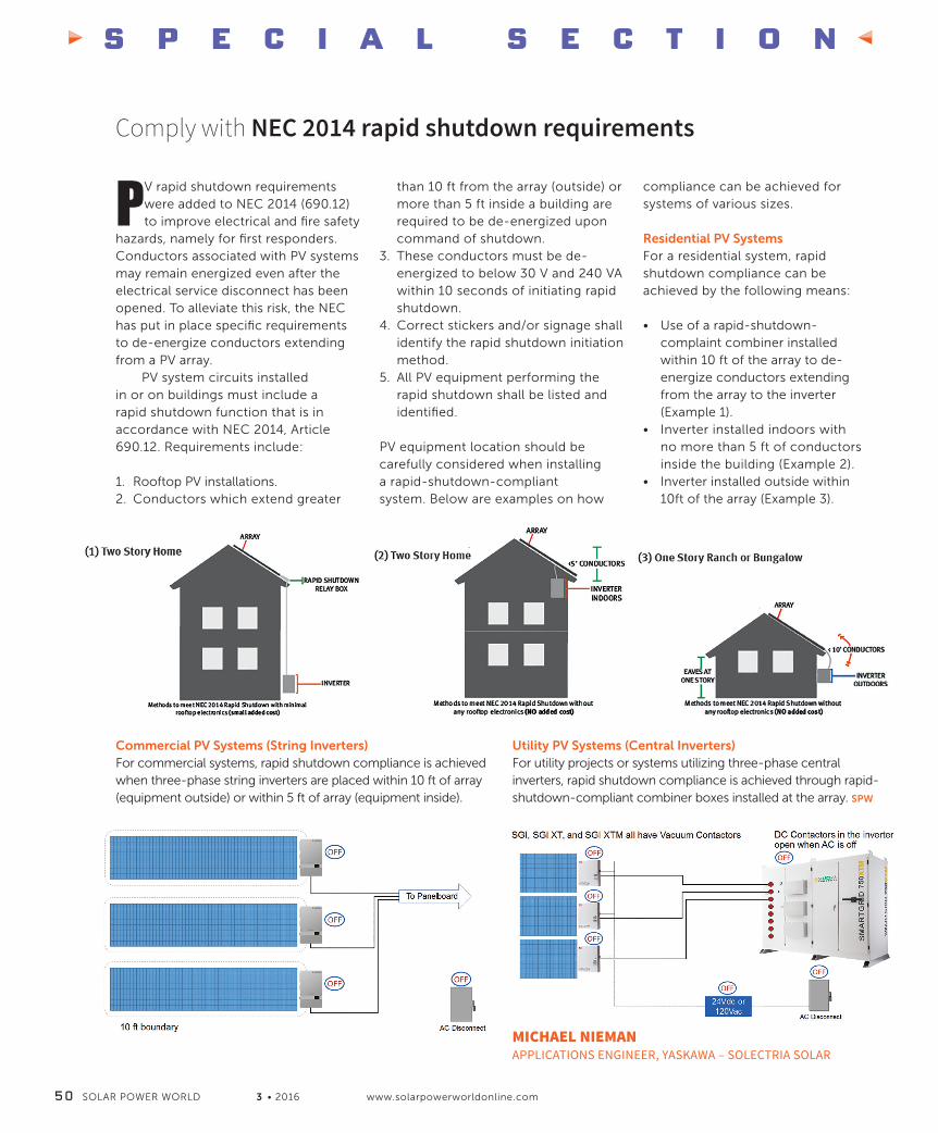
S P E C I A L S E C T I O N
5 0 SOLAR POWER WORLD 3 • 2016 www.solarpowerworldonline.com
Comply with NEC 2014 rapid shutdown requirements
PV rapid shutdown requirements were added to NEC 2014 (690.12) to improve electrical and fire safety
hazards, namely for first responders. Conductors associated with PV systems may remain energized even after the electrical service disconnect has been opened. To alleviate this risk, the NEC has put in place specific requirements to de-energize conductors extending from a PV array.
PV system circuits installed in or on buildings must include a rapid shutdown function that is in accordance with NEC 2014, Article 690.12. Requirements include:
1. Rooftop PV installations.2. Conductors which extend greater
than 10 ft from the array (outside) or more than 5 ft inside a building are required to be de-energized upon command of shutdown.
3. These conductors must be de-energized to below 30 V and 240 VA within 10 seconds of initiating rapid shutdown.
4. Correct stickers and/or signage shall identify the rapid shutdown initiation method.
5. All PV equipment performing the rapid shutdown shall be listed and identified.
PV equipment location should be carefully considered when installing a rapid-shutdown-compliant system. Below are examples on how
compliance can be achieved for systems of various sizes.
Residential PV Systems For a residential system, rapid shutdown compliance can be achieved by the following means:
• Use of a rapid-shutdown-complaint combiner installed within 10 ft of the array to de-energize conductors extending from the array to the inverter (Example 1).
• Inverter installed indoors with no more than 5 ft of conductors inside the building (Example 2).
• Inverter installed outside within 10ft of the array (Example 3).
Commercial PV Systems (String Inverters) For commercial systems, rapid shutdown compliance is achieved when three-phase string inverters are placed within 10 ft of array (equipment outside) or within 5 ft of array (equipment inside).
Utility PV Systems (Central Inverters)For utility projects or systems utilizing three-phase central inverters, rapid shutdown compliance is achieved through rapid-shutdown-compliant combiner boxes installed at the array. SPW
MICHAEL NIEMANAPPLICATIONS ENGINEER, YASKAWA – SOLECTRIA SOLAR
NABCEP section 3-16_Vs3SB.indd 50 3/7/16 6:59 PM

North America’s Most-Attended Solar EventMoscone Center, San Francisco
Exhibit now!
Hear it here first! Be part of the first major U.S. solar event of the year18,000 visitors connect with 550 international exhibitorsSolar & Energy Storage – The perfect match! Intersolar is co-located with ees®
co-located with
AZISNA2016_Solar Power World_Aussteller_235x283_Layout 1 24.11.15 11:25 Seite 1
Intersolar 1-16.indd 1 3/7/16 7:34 PM

S P E C I A L S E C T I O N
5 2 SOLAR POWER WORLD 3 • 2016 www.solarpowerworldonline.com
Prevent battery shorts with safe installation
Whether you are a veteran or installing your first battery-based system, it’s important to avoid
taking shortcuts when installing batteries. There is a real danger in creating a short circuit by unintentionally connecting the positive terminal to the negative terminal on a battery, causing the battery to deliver high current over a short period of time.
Short circuits are a potential health hazard and may also damage the battery’s internal construction impacting performance in the future. Excess current can cause a battery to overheat and potentially explode, releasing hydrogen gas and electrolytes.
Even if the short does not cause the battery to overheat, some stress on the internal construction may have occurred thus shortening overall performance, so it’s best to take all measures to avoid creating a short.
Follow these rules when installing batteries to reduce the risk of a short:
Plan aheadTake time to carefully plan your installation in advance. Plan every move
to avoid creating an opportunity for a short before you start working. A well thought out plan will help to avoid making sudden movements or dropping a tool, which is how most shorts occur.
Organize your toolsCarefully organize your tools close by your work area but away from the batteries, and avoid the temptation to rest any tools on the tops of the batteries where they might come in contact with battery terminals.
Use insulated tools Wherever possible, use non-metallic or insulated tools that protect from creating a short circuit. If such tools are difficult to find, wrapping the handle end of a tool with electrical tape may be the safest solution.
Remove metal objects and jewelryBefore working with batteries, take a moment to remove any metal objects
and jewelry that might create an opportunity for a short circuit and put them in a safe place away from your work area.
Avoid distractionsWhen working with batteries, don’t let something distract you that might result in creating a short circuit. Stay focused and avoid
taking your eyes off your work.
Protect yourselfRemember, when working with batteries, always wear proper eye protection, gloves and protective clothing to minimize your exposure to hazardous materials. SPW
KALYAN JANATECHNICAL PRODUCT MARKETING MANAGER, TROJAN BATTERY COMPANY
The installation of solar mounting structures is a repetitive and time-sensitive process, making it a perfect
setting for applying the principles of lean construction. Of course, some basic steps to installation can’t be changed, like drilling pilot holes or wearing safety harnesses. But crews can think and plan ahead on a larger scale. They can anticipate what will happen next and finish more quickly. For example, shaving off a single minute from a step repeated 60 times saves one hour of labor. To apply lean construction philosophy to projects, managers should think of projects as a production system.
Apply lean construction principles on rootftops
Quickly and efficiently executing a job contributes positively to a contractor’s bottom-line. Installation crews range in size from three members on a residential installation to 100 or more members on large-scale projects. Optimized operations maintain work flow, while minimizing costs and time, reducing materials and tools (especially on a roof) and eliminating wasted movements. Shaving a minute off a step that 60 installers do 60 times saves more than a week of labor. Lean solar construction works to drive waste out of processes, streamline work flow—including having the right tools
accessible—and dedicate appropriately skilled teams with tasks that work in parallel whenever possible.
A pre-determined plan is key to success. Here’s an example, based around a hypothetical residential installation:
Two people get on a roof with safety harnesses and construction aprons. One stays on the ground. Once anchored, one roof person marks the roof while the other locates rafters and inserts flashings. As marking finishes, that person helps complete flashings installations, a time-consuming phase of the project. Anticipating the roof team’s
NABCEP section 3-16_Vs3SB.indd 52 3/7/16 6:59 PM
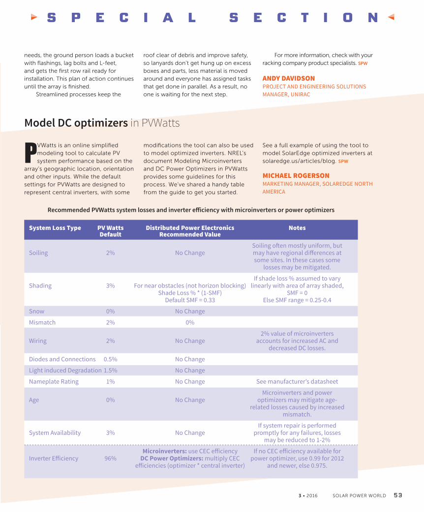
S P E C I A L S E C T I O N
3 • 2016 SOLAR POWER WORLD 5 3
System Loss Type PV Watts Distributed Power Electronics Notes Default Recommended Value
Soiling often mostly uniform, butSoiling 2% No Change may have regional differences at some sites. In these cases some losses may be mitigated.
If shade loss % assumed to varyShading 3% For near obstacles (not horizon blocking) linearly with area of array shaded, Shade Loss % * (1-SMF) SMF = 0 Default SMF = 0.33 Else SMF range = 0.25-0.4
Snow 0% No Change
Mismatch 2% 0%
2% value of microinvertersWiring 2% No Change accounts for increased AC and decreased DC losses.
Diodes and Connections 0.5% No Change
Light induced Degradation 1.5% No Change
Nameplate Rating 1% No Change See manufacturer’s datasheet
Microinverters and powerAge 0% No Change optimizers may mitigate age- related losses caused by increased mismatch.
If system repair is performedSystem Availability 3% No Change promptly for any failures, losses may be reduced to 1-2%
Microinverters: use CEC efficiency If no CEC efficiency available forInverter Efficiency 96% DC Power Optimizers: multiply CEC power optimizer, use 0.99 for 2012 efficiencies (optimizer * central inverter) and newer, else 0.975.
Model DC optimizers in PVWatts
PVWatts is an online simplified modeling tool to calculate PV system performance based on the
array’s geographic location, orientation and other inputs. While the default settings for PVWatts are designed to represent central inverters, with some
modifications the tool can also be used to model optimized inverters. NREL’s document Modeling Microinverters and DC Power Optimizers in PVWatts provides some guidelines for this process. We’ve shared a handy table from the guide to get you started.
Recommended PVWatts system losses and inverter efficiency with microinverters or power optimizers
See a full example of using the tool to model SolarEdge optimized inverters at solaredge.us/articles/blog. SPW
MICHAEL ROGERSONMARKETING MANAGER, SOLAREDGE NORTH AMERICA
needs, the ground person loads a bucket with flashings, lag bolts and L-feet, and gets the first row rail ready for installation. This plan of action continues until the array is finished.
Streamlined processes keep the
roof clear of debris and improve safety, so lanyards don’t get hung up on excess boxes and parts, less material is moved around and everyone has assigned tasks that get done in parallel. As a result, no one is waiting for the next step.
For more information, check with your racking company product specialists. SPW
ANDY DAVIDSONPROJECT AND ENGINEERING SOLUTIONS MANAGER, UNIRAC
NABCEP section 3-16_Vs3SB.indd 53 3/7/16 6:59 PM

S P E C I A L S E C T I O N
5 4 SOLAR POWER WORLD 3 • 2016 www.solarpowerworldonline.com
Minimize the effects of thermal expansion and contraction
It’s easy to think about solar systems getting hot—their potential is realized when the sun beats down on them.
Temperatures on roofs can reach beyond 200°F. But in most climates, systems get cold, too. Even in Hawaii, panels and racking can experience temperature swings totaling more than 100°F. Concern about temperature becomes relevant when discussing mechanical connections for weatherization and human safety.
Typically, solar panels have accounted for temperature swing, and the mechanical expansion and contraction associated with it, through flexibility in construction materials and, on a relatively small scale, in each module. To appropriately account for temperature fluctuations on a system level, however, the racking must also be considered.
The issue becomes most critical when mechanically attached materials, such as aluminum rails and a wood deck, expand at different rates. A steel roof with metal purlins whose structure remains in the shade is also worth considering. How
elevated the array is above the roof will also influence how much ventilation it gets, contributing to temperature. This is important because attachments can loosen their water seals or shear standoffs and hardware over time. For a full set of calculations, please visit SunModo’s website for an application note. In general, the rules of thumb mentioned below are useful.
If the installation location is determined to be a mild climate with ambient temperature change of less than 60°F across the year, then creating a thermal measure every 80 in. is suggested. In extreme climates (101 to 130°F ambient change) and moderate climates (60 to 100°F ambient change) this should be accounted for at every 40 in. Systems with shorter rails experience less accumulated change than engineered deflection values can handle.
Installers have two options. An installation can be designed as separate
arrays with stand offs and end clamps stopping and starting at the thermal break. Or installers can use a thermal splice, sliding clip and bonding strap, which makes the array appear continual.
If the latter option is chosen, it is imperative that the gap be set correctly. Over-setting the gap would create a problem almost as bad as no thermal break at all: the rails could become disconnected. So it is important to note the gap chart and use an IR temp gun to account for the actual installation temperature of which the expanding and contracting rails will begin their movement.
A helpful tool from SunModo can help measure a system with thermal gaps. When sunlight-elevated rooftop temperatures are thoroughly considered, many factors are influenced, including system performance, conductor sizing and, most importantly, worker health. In the same light, planning for thermal expansion in arrays will keep attachments weatherized and PV racking lasting a lifetime. SPW
JEREMY TAYLOR, PRODUCT SYSTEM ENGINEER, SUNMODO
NABCEP section 3-16_Vs3SB.indd 54 3/7/16 6:59 PM

INNOVATION AND COLLABORATION
AT ITS CORE
SEPTEMBER 12-15, 2016LAS VEGAS CONVENTION CENTER - NORTH HALL & WESTGATE HOTEL
WWW.SOLARPOWERINTERNATIONAL.COM
Register and book your housing for the largest solar trade show in North America!
More than 15,000 solar industry professionalswill convene in Las Vegas for SPI.
Powered by:
NEW to SPI: A Smart Home Demonstration
See how solar installations can power smart technology and
reduce overall costs for consumers and businesses.
Whether you’re an installer, manufacturer, or distributor,
understanding how to incorporate smart technology into your
business model will positively impact your bottom line.
SPI 3-16.indd 7 3/7/16 7:36 PM

5 6 SOLAR POWER WORLD 3 • 2016 www.solarpowerworldonline.com
[ C O N T R A C T O R S C O R N E R ]
Anthony Roden
Anthony Roden is president of
Tennessee Solar Solutions.
Success in business meanspracticing what you preach
Tennessee Solar SolutionsChattanooga, TennesseeBy Kelly Pickerel, Associate Editor
When Tennessee Solar Solutions formed nine years ago, there wasn’t a lot of competition out there.
“In 2007, in our area, solar wasn’t big,” said Anthony Roden, president. “I was one of the first solar contractors in Tennessee. The fact that I feel like I’m making a difference, I find a lot of enjoyment in that.”
There has been a big upswing in solar in the state in the last decade, and business has boomed for the company. Tennessee Solar Solutions does do more residential projects, but a recent uptick in agriculture business has shifted the company’s breakdown to 60% residential and 40% commercial.
“We’ve seen a lot of large growth,” Roden said. “Everyone seems to be very interested in renewables, specifically solar. That’s a good thing. When I first started in 2007, it was just myself and I did a lot of subbing out of the work. Now we have about 24 employees, so we’ve seen a lot of growth.”
Tennessee Solar Solutions gives back by participating in local solar associations. Roden is on the board of directors for Tennessee Solar Energy Association (TSEA), and Ginny Kincer, Tennessee Solar Solutions’ COO, is part of the board of directors for Tennessee Solar Energy Industries Association (TenneSEIA).
“We want to continue to help the industry grow as much as we can,” Roden said. “We feel those two outlets are ways that allow us to do that and help give back.”
One thing Roden hopes to resolve is permitting. Still one of the more common complaints from contractors across the country, easing permitting frustration could be something local solar chapters help with.
“It should be a simple process; however, a lot of your smaller rural areas, your co-ops aren’t really familiar with the product and what it takes,” he said. “We see a lot of issues there. It’s not really that big of a deal to make all this work together. Streamlining of the permitting would be one of our largest obstacles. I would definitely love to see that change.”
I was one of the first solar contractors in Tennessee. The fact that I feel like I’m making a difference, I find a lot of enjoyment in that.
Contractors Corner_2-16_Vs2kp.indd 56 3/7/16 7:04 PM

[ C O N T R A C T O R S C O R N E R ]
3 • 2016 SOLAR POWER WORLD 5 7
In the meantime, Tennessee Solar Solutions keeps plugging away, doing the best job possible. One way the company stands out from the crowd, Roden said, is because of its certification and training.
“In today’s market, it seems like everyone advertises they install solar. You’ve got roofing contractors, mechanical contractors, electrical contractors, everyone does solar evidently,” he said. “We find ourselves at Tennessee Solar Solutions having to go and fix the work of these companies that do solar on the side. NABCEP is a way for us to stand apart and it shows we are open to getting that extra level of certification even though we carry a general contractors license and an electrical contractors license in-house. Sometimes that just isn’t enough. You need to be certified in solar.”
Also, practicing what they preach is something everyone at Tennessee Solar Solution takes to heart.
“The majority of the employees that work [here] have solar on our homes,” Roden said. “I think that’s important to be able to utilize what you’re trying to sell. To me, if someone is trying to sell me a product as specific as solar, if that person doesn’t have it on their home, that would make me less interested. It’s very important to be able to practice what we preach.” SPW
Contractors Corner_2-16_Vs2kp.indd 57 3/7/16 7:04 PM

[ S O L A R S N A P S H O T ]
5 8 SOLAR POWER WORLD 3 • 2016 www.solarpowerworldonline.com
According to GTM Research, 20 U.S. states are currently at grid parity, and 42 states are expected to reach it by 2020. Residential solar reaches grid parity
when the levelized cost of solar energy falls below gross electricity bill savings in the first year of a solar PV system’s life.
Source: GTM Research U.S. Residential Solar Economic Outlook 2016-2020
Through a partnership with Mercatus and EnergySage, SEPA obtained information on PV pricing
from nearly 11,000 aggregated residential, nonresidential (including commercial and industrial),
and utility-scale solar prices from selected states. They found average national residential prices
ranged from $3.00 to $4.00 per watt.
SEPA found interesting outliers in certain states and regions. For example, Florida’s
inexpensive electricity and lack of solar incentives have generally kept prices quite low, with
an average price of $2.51 per watt. Washington state, on the other hand, has a solar power
performance payment incentive, which is significantly higher for projects using panels
manufactured in the state. The resulting average price of $4.43 per watt was the highest
average price in the sample data. According to EnergySage, New York and Massachusetts have
vibrant solar markets with some limited price transparency among consumers and between
vendors, factors that pushed the average price of solar to $4.03 and $4.20 per watt respectively.
Source: SEPA Market Snapshot Series: Photovoltaic System Price Quotes From Selected States 2014-2015
Average Residential Cost (USD/WATT) by Region, 2014-2015
20 States Reach Grid Parity
Snapshot_3-16_Vs2KZ.indd 58 3/7/16 7:12 PM

Apply Noww w w . s o l a r p o w e r w o r l d o n l i n e . c o m
2 0 1 6 T O P S O L A R C O N T R A C T O R S L I S T
THE sun is rising on your solar
business.Join the Definitive List of
Solar Contractors.
The annual Solar Power World magazine Top Solar Contractors List is the most
recognized list of solar contractors and developers in the U.S. and Canada.
The application is simple and free, and being listed can be invaluable to your marketing
efforts and team spirit. Contractors will be
listed according to megawatts
installed in 2015. The
application is now open!
5OO
TOP 500 (house) 3-16.indd 7 3/8/16 10:39 AM

CONNECT WITH US!CHECK US OUT ON ISSUU!
NEW
SALES
Jim Powers
312.925.7793
@jpowers_media
Neel Gleason
312.882.9867
@wtwh_ngleason
Todd Christenson
440.381.9048
@wtwh_todd
Tom Lazar
408.701.7944
@wtwh_Tom
Jessica East
330.319.1253
@wtwh_MsMedia
Michelle Flando
440.381.9110
@mflando
LEADERSHIP TEAM
VP of Sales
Mike Emich
508.446.1823
@wtwh_memich
Managing Director
Scott McCafferty
310.279.3844
@SMMcCafferty
EVP
Marshall Matheson
805.895.3609
@mmatheson
Associate Publisher
Courtney Seel
440.523.1685
@wtwh_CSeel
[ A D I N D E X ]
AceClamp ..................................................................... 47Axitec Solar USA ...........................................................12Baja Construction ........................................................31Chint Power Systems ................................................IFCCohnReznick ...................................................................7Dunkermotoren, part of Ametek.............................. 23EagleView Technologies .............................................41EcoFasten Solar ............................................................ 11Everest Solar ................................................................. 39GameChange Solar LLC................................................3GreenTech Media......................................................... 45Intersolar North America ............................................51Kaco New Energy ........................................................48Kipp & Zonen .................................................................15Magerack Corporation ...............................................40Mounting Systems Inc. ............................................... 27NineFasteners............................................................... 24Omco Solar ................................................................ IBCPanasonic Eco Solutions ..............................................5Snake Tray ..................................................................... 36Solar Power International PVA.................................. 55Solar SpeedRack .......................................................... 28SolarEdge Technologies ............................................ 37SolarRoofHook.com/QuickScrews ........................... 4Sun Action Trackers .................................................... 10SunLink .......................................................................... 32SunModo ........................................................................21Unirac ............................................................................... 1University of Wisconsin - Madison .....................InsertYaskawa-Solectria Solar ............................................ BC
6 0 SOLAR POWER WORLD 3 • 2016 www.solarpowerworldonline.com
Follow the whole team on twitter @SolarPowerWorld
CONNECT WITH US!
Ad index_March 2016_Vs1.indd 60 3/8/16 11:41 AM

IT’S NOT HARD TO FIND USARIZONA, OHIO, INDIANA, ALABAMA
Rol l Forming, Stamping, Fastener Insert ion, Custom Assembly
OVER 6 GW OF CUSTOM SOLAR MOUNTING STRUCTURES INSTALLED
60 2 .352.2700 www.omcosolar .com sa les@omc o fo r m.c o m
Omco 3-16.indd 1 3/8/16 10:18 AM

SOLECTRIA IS OWNED BY YASKAWA$4B Company
11,500 Employees
Over 22 Million Inverters Installed
22 Manufacturing Facilities Worldwide
Celebrating 100 Years of Manufacturing
www.solectria.com | [email protected]
SIMPLIFYING SOLAR
Yaskawa 11-15_Vs1.indd 105 3/7/16 7:37 PM